US7177391B2 - Imaging inspection apparatus - Google Patents
Imaging inspection apparatusDownload PDFInfo
- Publication number
- US7177391B2 US7177391B2US11/091,521US9152105AUS7177391B2US 7177391 B2US7177391 B2US 7177391B2US 9152105 AUS9152105 AUS 9152105AUS 7177391 B2US7177391 B2US 7177391B2
- Authority
- US
- United States
- Prior art keywords
- conveyor
- inspection apparatus
- imaging inspection
- articles
- main portion
- Prior art date
- Legal status (The legal status is an assumption and is not a legal conclusion. Google has not performed a legal analysis and makes no representation as to the accuracy of the status listed.)
- Expired - Lifetime
Links
- 238000007689inspectionMethods0.000titleclaimsabstractdescription66
- 238000003384imaging methodMethods0.000titleclaimsabstractdescription48
- 238000004458analytical methodMethods0.000claimsabstractdescription8
- 238000012545processingMethods0.000claimsabstractdescription8
- 238000002591computed tomographyMethods0.000claimsabstractdescription6
- 238000012360testing methodMethods0.000description10
- 238000000034methodMethods0.000description8
- 239000000463materialSubstances0.000description6
- 230000005855radiationEffects0.000description5
- 238000003491arrayMethods0.000description4
- 238000001514detection methodMethods0.000description4
- 238000010894electron beam technologyMethods0.000description4
- 239000002360explosiveSubstances0.000description4
- 235000013305foodNutrition0.000description4
- 238000005286illuminationMethods0.000description4
- 238000013459approachMethods0.000description3
- 230000007423decreaseEffects0.000description3
- 239000003814drugSubstances0.000description3
- 229940079593drugDrugs0.000description3
- 238000012986modificationMethods0.000description3
- 230000004048modificationEffects0.000description3
- 238000007781pre-processingMethods0.000description3
- 230000002829reductive effectEffects0.000description3
- 230000004044responseEffects0.000description3
- 238000002441X-ray diffractionMethods0.000description2
- 230000002411adverseEffects0.000description2
- 238000000354decomposition reactionMethods0.000description2
- 239000004615ingredientSubstances0.000description2
- 239000000203mixtureSubstances0.000description2
- 238000005070samplingMethods0.000description2
- 239000007787solidSubstances0.000description2
- 230000003595spectral effectEffects0.000description2
- 230000000007visual effectEffects0.000description2
- 229910000831SteelInorganic materials0.000description1
- 230000001154acute effectEffects0.000description1
- 230000002238attenuated effectEffects0.000description1
- 230000003139buffering effectEffects0.000description1
- 230000008859changeEffects0.000description1
- 238000010276constructionMethods0.000description1
- 230000007547defectEffects0.000description1
- 238000002059diagnostic imagingMethods0.000description1
- 230000000694effectsEffects0.000description1
- 238000005516engineering processMethods0.000description1
- 238000004519manufacturing processMethods0.000description1
- 238000005259measurementMethods0.000description1
- 238000010606normalizationMethods0.000description1
- 230000036961partial effectEffects0.000description1
- 230000000149penetrating effectEffects0.000description1
- 239000000843powderSubstances0.000description1
- 230000001902propagating effectEffects0.000description1
- 230000001681protective effectEffects0.000description1
- 230000009467reductionEffects0.000description1
- 230000002441reversible effectEffects0.000description1
- 238000012552reviewMethods0.000description1
- 230000011218segmentationEffects0.000description1
- 230000035945sensitivityEffects0.000description1
- 238000007619statistical methodMethods0.000description1
- 239000010959steelSubstances0.000description1
- 239000000126substanceSubstances0.000description1
- 230000001360synchronised effectEffects0.000description1
Images


Classifications
- G—PHYSICS
- G01—MEASURING; TESTING
- G01V—GEOPHYSICS; GRAVITATIONAL MEASUREMENTS; DETECTING MASSES OR OBJECTS; TAGS
- G01V5/00—Prospecting or detecting by the use of ionising radiation, e.g. of natural or induced radioactivity
- G01V5/20—Detecting prohibited goods, e.g. weapons, explosives, hazardous substances, contraband or smuggled objects
- B—PERFORMING OPERATIONS; TRANSPORTING
- B65—CONVEYING; PACKING; STORING; HANDLING THIN OR FILAMENTARY MATERIAL
- B65G—TRANSPORT OR STORAGE DEVICES, e.g. CONVEYORS FOR LOADING OR TIPPING, SHOP CONVEYOR SYSTEMS OR PNEUMATIC TUBE CONVEYORS
- B65G21/00—Supporting or protective framework or housings for endless load-carriers or traction elements of belt or chain conveyors
- B65G21/10—Supporting or protective framework or housings for endless load-carriers or traction elements of belt or chain conveyors movable, or having interchangeable or relatively movable parts; Devices for moving framework or parts thereof
- B65G21/14—Supporting or protective framework or housings for endless load-carriers or traction elements of belt or chain conveyors movable, or having interchangeable or relatively movable parts; Devices for moving framework or parts thereof to allow adjustment of length or configuration of load-carrier or traction element
- G—PHYSICS
- G01—MEASURING; TESTING
- G01N—INVESTIGATING OR ANALYSING MATERIALS BY DETERMINING THEIR CHEMICAL OR PHYSICAL PROPERTIES
- G01N23/00—Investigating or analysing materials by the use of wave or particle radiation, e.g. X-rays or neutrons, not covered by groups G01N3/00 – G01N17/00, G01N21/00 or G01N22/00
- G01N23/02—Investigating or analysing materials by the use of wave or particle radiation, e.g. X-rays or neutrons, not covered by groups G01N3/00 – G01N17/00, G01N21/00 or G01N22/00 by transmitting the radiation through the material
- G01N23/04—Investigating or analysing materials by the use of wave or particle radiation, e.g. X-rays or neutrons, not covered by groups G01N3/00 – G01N17/00, G01N21/00 or G01N22/00 by transmitting the radiation through the material and forming images of the material
- G01N23/046—Investigating or analysing materials by the use of wave or particle radiation, e.g. X-rays or neutrons, not covered by groups G01N3/00 – G01N17/00, G01N21/00 or G01N22/00 by transmitting the radiation through the material and forming images of the material using tomography, e.g. computed tomography [CT]
- G—PHYSICS
- G01—MEASURING; TESTING
- G01N—INVESTIGATING OR ANALYSING MATERIALS BY DETERMINING THEIR CHEMICAL OR PHYSICAL PROPERTIES
- G01N2223/00—Investigating materials by wave or particle radiation
- G01N2223/40—Imaging
- G01N2223/419—Imaging computed tomograph
Definitions
- the inventionrelates to inspection apparatus designed for inspecting articles such as luggage, baggage, mail, etc. More particularly, the invention relates to such apparatus which utilize X-ray imaging and the like.
- imaging inspection apparatusincluding those which utilize X-ray imaging. Such apparatus are used to inspect articles such as personal luggage of airplane travelers at airports for such undesirable items as explosives and drugs.
- XCT apparatusare in wide use in the medical field for providing medical imaging such as patient body X-rays.
- XCT(often referred to in the medical profession simply as “CT scanning”) produces a cross sectional image from a grouping of attenuation measurements taken at different angles about an object such as a patient's chest or head, while the patient is maintained in a stationary position.
- the resulting scan datais utilized to automatically identify objects of interest, which identification is further verified through automatic analysis of such attributes as shape, texture, context, and X-ray diffraction.
- the objects of interestare then reconstructed and displayed on a computer monitor for visual analysis by the apparatus operator.
- a continuous, XCT imaging systemincludes a conveyor which moves a closed package for being scanned along the conveyor past three spaced sensing stations. At each sensing station a plurality of X-ray sources each emit a fan beam in the same scan plane which passes through the package to a plurality of detectors opposite the X-ray sources.
- One scanis a vertical perpendicular scan plane relative to the direction of travel of the package along the conveyor belt and the remaining two scan planes are horizontal scan planes at right angles and transverse to the direction of travel.
- One horizontal scan planeis a left to right scan plane while the remaining scan plane is a right to left scan plane.
- Each detectorprovides multiple energy outputs for the same data point in a scan slice, and the detector outputs are stored until all three sensing stations have scanned the same cross sectional view of the package in three directions. Scans are sequentially taken as the package moves continuously through the sensing stations and scanned data corresponding to cross sectional views of the package is accumulated. The stored data is calibrated and normalized and then used in a Computer Tomographic algebraic reconstruction technique.
- multi-spectral CT reconstructionwhere the density of a reconstructed object is determined by the attenuation which it causes in the scanning X-rays while the atomic number of the object is determined from the multiple energy scan output.
- the density and atomic numberare compared to a table containing density and atomic number identification values for specific objects to be located.
- the apparatusconsists of an X-ray source, a 2-dimensional X-ray detector, a beam selector, and a second 2-dimensional X-ray detector.
- the subjectis located between the X-ray source and first detector.
- the beam selectorprevents primary X-rays from reaching selected locations of the second (rear) detector.
- a pair of primary dual-energy imagesis obtained at the rear detector.
- a dual-energy data decomposition methoda low-resolution primary X-ray first detector image is calculated, from which a high-resolution primary dual-energy image pair is calculated.
- the data decomposition methodis used to calculate a pair of high-spatial-resolution material composition images.
- U.S. Pat. No. 6,018,562issued Jan. 25, 2000, there is described an apparatus for automatic recognition and identification of concealed objects and features thereof, such as contraband in baggage or defects in articles of manufacture.
- the apparatususes multiple energy X-ray scanning to identify targets with a spectral response corresponding to a known response of targets of interest. Detection sensitivity for both automatic detection and manual inspection are improved through the multiple-energy, multi-spectral technique. Multi-channel processing is used to achieve high throughput capability. Target identification may be verified through further analysis of such attributes as shape, texture, and context of the scan data.
- the apparatususes a statistical analysis to predict the confidence level of a particular target identification. A radiograph, CT image, or both may be reconstructed and displayed on a computer monitor for visual analysis by the apparatus operator. Finally, the apparatus may receive and store input from the operator for use in subsequent target identification.
- the X-ray source and the array of detectors in this known systemare positioned so that the X-ray paths between the source and each of the detectors all lie in the same plane (hereinafter the “rotation plane” or “scanning plane”) which is normal to the rotation axis of the disk. Since the X-ray paths originate from what is substantially a point source and extend at different angles to the detectors, the X-ray paths form a “fan beam.”
- the X-rays incident on a single detector at a measuring interval during a scanare commonly referred to as a “ray”, and each detector generates an analog output signal indicative of the intensity of its corresponding ray.
- the analog output signal generated by each detectoris representative of an integral of the density of all the mass disposed between that detector and the X-ray source (i.e., the density of the mass lying in the detector's corresponding ray path) for that measuring interval.
- a real time radiographic test systemwhich consists of a protective housing and a conveyor for conveying articles to be tested through the housing.
- a real time radiographic test instrumentis located in the housing for performing a real time radiographic test on the article.
- the test instrumentincludes X-ray equipment disposed for directing an X-ray beam within the housing in a direction which does not intersect the conveyor.
- An article-handling actuatoris located in the housing for repositioning an article from the conveyor to a position in registry with the X-ray beam, for maintaining the article in registry with the X-ray beam while the real time radiographic test is performed on the article and thereafter returning the article to the conveyor.
- the article-handling actuator and the X-ray equipmentare designed such that each article to be tested is positioned substantially identically relative to the X-ray beam.
- an X-ray analysis devicefor determining the mean atomic number of a material mass by locating a broad band X-ray source on one side of a testing station and on the other, a detector, comprising a target having X-ray detectors positioned adjacent thereto.
- One of the detectorsis positioned and adapted to receive X-rays scattered by the detector target in a generally rearward direction and the other detector is positioned and adapted to detect forwardly propagating X-rays scattered off axis typically by more than 30 degrees, due to so-called “Compton scatter.”
- Each of the X-ray detectorsprovides signals proportional to the number of X-ray photons incident thereon.
- the apparatusfurther includes means responsive to the two detector outputs which form a ratio of the number of photons detected by the two detectors and forms a numerical value thereof.
- a look-up table containing mean atomic numbers for given numerical ratios for different materialsis used, as is a means for determining from the look-up table the atomic number corresponding to the numerical ratio obtained from the outputs of the two detectors.
- the atomic numberis provided as an output signal.
- Deflection voltage signalsare applied to the X and Y deflection coils, and cause the X-ray source to rotate in a circular trace path.
- An additional DC voltage applied to the X or Y deflection coilwill cause the circular path traced by the X-ray source to shift in the X or Y direction by a distance proportional to the magnitude of the DC voltage. This causes a different field of view, which is displaced in the X or Y direction from the previously imaged region, to be imaged. Changes in the radius of the X-ray source path result in a change in the Z level of the imaged focal plane.
- the present inventiondefines a new and unique inspection apparatus which, in one embodiment, uses imaging technology (e.g., XCT scanning) in combination with a moving conveyor which substantially prevents undesirable motion to the articles moving along the conveyor and being inspected.
- imaging technologye.g., XCT scanning
- the apparatusis thus able to effectively inspect (e.g., scan) articles because the articles move along its conveyor in a smooth manner during inspection.
- an imaging inspection apparatusfor inspecting objects located within moving articles
- the imaging inspection apparatuscomprising a conveyor for conveying articles having objects located therein along a line of travel through an inspection location located substantially within said imaging inspection apparatus, the conveyor being of a substantially flat orientation during said conveying of said articles, a frame structure, a plurality of imaging inspection devices positioned on said frame and adapted for directing beams onto the articles as the articles move on said conveyor and pass along the path of travel through said inspection location to thereby inspect the articles, and for providing output signals as a result of this inspecting, and a processing and analysis assembly adapted for receiving the output signals from the plurality of imaging inspection devices and for analyzing the output signals to identify the objects within the moving articles.
- the conveyoris not physically coupled to the frame structure and is also adapted for being folded to a non-flat orientation of a lesser length than its flat orientation when the conveyor is not conveying the articles along the path of travel.
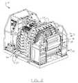
- FIG. 1is a front perspective view of an imaging inspection apparatus for inspecting objects located within moving articles, according to one embodiment of the invention
- FIG. 2is a rear perspective view of the imaging inspection apparatus for inspecting objects located within moving articles as shown in FIG. 1 ;
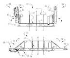
- FIGS. 3 and 4are side, elevational views, illustrating one embodiment of the conveyor of the invention in the raised (closed) and lowered (opened, operating) positions, respectively, FIG. 4 being smaller in scale;
- FIG. 5is a partial end view of the apparatus of FIGS. 1 and 2 , on an enlarged scale over the views of FIGS. 1–4 , showing the spaced positioning relationship of the invention's conveyor relative to the remaining structure of the apparatus, according to one embodiment of the invention.
- FIGS. 1 and 2there is illustrated an imaging inspection apparatus 21 according to one embodiment of the invention.
- apparatus 21is particularly designed for inspecting (and detecting) objects (not shown) which might be located within closed articles such as personal luggage of an airplane traveler.
- the apparatusis ideally designed for placement and use within an airport or other transportation facility in which large numbers of such articles are received and transported.
- Apparatus 21is adapted for inspecting and detecting concealed objects such as explosives, weapons, etc., including in solid and powder form. Further explanation of how apparatus operates is provided below.
- One example of such an article, this being a suitcase (luggage) 25is shown in FIG. 5 . Understandably, the apparatus inspects several such articles as these move therethrough.
- Apparatus 21includes a plurality of imaging inspection devices 23 , which, in a preferred embodiment, are individual X-ray Computer Tomography (XRT) scanning devices. That is, each device is preferably an individual X-ray photon source, which are collimated to provide what may be referred to as a “fan beam.” In one embodiment, these fan beams will each be collimated to a beam thickness of about 1 mm. over a distance of at least about 141 cm, with a divergence of about 0.7 milli-radians (or about 0.04. degree). Beams of such dimensions are preferred to substantially prevent background scatter and radiation leakage.
- XRTX-ray Computer Tomography
- inspection devices 23are arranged in three groupings G 1 , G 2 and G 3 , with each grouping oriented in a particular orientation relative to the conveyor and thereby to the path of travel of the articles through the apparatus.
- Each groupingdirects X-ray beams along a plane onto the articles, there thus being a total of three planes of beams (A, B and C, shown in FIGS. 3 and 4 ) each article passes through while being inspected.
- groupings G 1 and G 2each include seven devices 23 , and direct beams from opposite sides of the apparatus in a substantially horizontal manner, such that each article passing through the apparatus will receive beams toward the sides thereof.
- Grouping G 3includes fourteen devices 23 and directs beams from the top of the apparatus downwardly onto the articles, so that said articles will receive beams on the tops thereof. Each article is thus subject to pluralities of beams on at least three sides thereof. As the articles move through the three scan planes A, B and C, a number of lines of projection image data are formed for the scanned article in each scan plane. These lines of projection image data show the attenuation of the X-rays by the article and the object(s) (if any) therein. The density of an object scanned within the package can be calculated from the attenuation of the X-rays caused by the object.
- Detectors used in each grouping 27are preferably of conventional construction and thus known in the art. Further description of this operation is provided in the above-mentioned U.S. Pat. No. 6,236,709.
- each detector array 27outputs five energy levels for each scan to provide multiple energies for the same set of data points.
- systems of this typewhich use multiple filters to obtain multi-energy outputs from a detector are known.
- the detector systemscan be constructed so that each detector provides an output signal to five comparators, each of which receives a different threshold voltage from a threshold source.
- the output of each comparatoris a different energy level signal which represents the intensity of the spectral range above the comparator threshold input.
- the proportional decrease in the number of photonsis a function of material chemical composition (i.e. atomic number).
- the processing and analysis assembly 28( FIG. 1 ) for the imaging apparatus of the invention is preferably similar to that used in U.S. Pat. No. 6,236,709, mentioned above.
- This assemblyreceives inputs from a sensor unit which includes the detector arrays 27 .
- a preprocessing unitinterfaces directly with the sensor units to provide buffering of the output data received from the sensor units. Timing is controlled by an input from a shaft encoder.
- an address generator in the preprocessing unitwhich is connected to a plurality of reconstruction signal processing boards generates a board address to determine which of the reconstruction signal processing boards will receive a current frame of data.
- Each reconstruction boardas defined in U.S. Pat.
- No. 6,236,709contains several (e.g., up to sixteen) computer chips. These systems cooperate to provide calibration and normalization of the raw input data, and then conventional multi-spectral XCT reconstruction which includes algebraic reconstruction. During this reconstruction, each slice through the article being inspected is reconstructed at five different energies which are required to obtain the atomic number of an inspected (sensed) object.
- the algebraic reconstruction datais then sent to a detection and segmentation section of the apparatus which detects the atomic number and density of a scanned object located within one of the articles.
- the linear X-ray attenuation coefficient muis proportioned to the density.
- the logarithm of the relative intensity of the X-ray beamis proportioned to the integral of the density of the material within the beam.
- the density and atomic number informationis compared in a classification unit with information (criteria) within a reference table containing density and atomic number information for specific objects to be identified. This identification data and the reconstructed image data is then sent (preferably over a VME bus to a VME computer).
- the reconstructed XCT image datais displayed on the operator's console for review by the apparatus operator (and others, if desired). Processing of the data obtained from the scanning is preferably accomplished using the methodology (including the described ART algorithm, which employs a square grid of basis functions, centered at defined pixel locations all of the same form and diameter) described in U.S. Pat. No. 6,236,709, and further description is not believe necessary.
- FIGS. 3–5better illustrate the conveyor 31 of the invention.
- Conveyor 31in accordance with a preferred embodiment of the invention, includes three portions, a main body portion 37 , and two opposing end portions 33 and 35 .
- End portion 33is also seen in FIG. 1
- opposite end portion 35is also seen in FIG. 2
- both of these end portions 33 and 35 in FIGS. 1 and 2being in the withdrawn, closed position.
- these endsare substantially vertically oriented in an upward orientation relative to the substantially horizontal, main body portion 37 of conveyor 31 .
- FIGS. 3 and 4are the three planes A, B and C, along which the groupings G 1 , G 2 and G 3 of devices 23 project their respective beams. Devices 23 are not shown in FIGS.
- each plane A, B and Cpasses through only main body portion 37 and not through either of the end portions 33 or 35 . It is further seen in these FIGS. 3 and 4 that main body portion 37 does not include a gap therein; that is, the single belt 41 (see more below) used for the conveyor extends across the body portion 37 and does not include a gap or other form of opening therein.
- conveyor 31is shown in FIG. 4 as being in its substantially flat (or planar) operating position to accept and pass (move) articles such as suitcase 25 there-along.
- articlesare placed on portion 33 and conveyed (moved) to the body portion 37 and finally to the remaining end portion 35 , from which it is then removed (or drops off) the conveyor.
- the articlepasses through planes A, B and C, where individual groupings of scans are taken.
- this movementoccurs with substantially no adverse motion (e.g., excessive vibration) using the conveyor of this invention, such adverse motion, as explained above, possibly altering the readings of the scanned article.
- the inventionaccomplishes this unique motion using a single belt 41 and a single drive (motor) 43 , while spacedly positioning the conveyor having these two components thereon upon a support deck structure 51 (see especially FIG. 5 ) separate from the frame structure 53 that holds the remainder of the apparatus, including particularly devices 23 and the detectors of each grouping 27 .
- This spacingis best seen in FIG. 5 .
- drive motor 43is located on end portion 35 , even further spacing it from the main support structure for the apparatus remainder.
- drive motor 43is a one horsepower, 480 VAC, three phase, reversible electric motor with rubber lagging for enhanced belt traction.
- the rollers used to carry the beltare each of about 6.5 inch diameter and crowned for belt tracking.
- the beltitself possesses a width of one meter (39.3 inches).
- the belt speedmay vary from about 1.22 to about 36.6 meters per minute (or about four to 120 feet per minute).
- the motor speedis controlled using a variable frequency drive.
- an imaging inspection apparatuswhich assures smooth movement of the articles being inspected such that effective scanning thereof will occur.
- the apparatus as defined hereinis able to accomplish this while also allowing length reduction of the overall apparatus length by virtue of folding of the conveyor to a non-operating position.
- the example illustratedshows the conveyor in a substantially perpendicular orientation when in the “non-flat” orientation, this is not meant to limit the invention in that other angular orientations, both acute and obtuse, may be used.
- the conveyor's operational length while in the flat orientationwas about 16.3 feet, and reduced to only about 10 feet when in the orientation shown. This represents a decrease in overall length of almost forty percent.
Landscapes
- Physics & Mathematics (AREA)
- General Physics & Mathematics (AREA)
- Health & Medical Sciences (AREA)
- Engineering & Computer Science (AREA)
- Life Sciences & Earth Sciences (AREA)
- Analytical Chemistry (AREA)
- General Health & Medical Sciences (AREA)
- Radiology & Medical Imaging (AREA)
- Pulmonology (AREA)
- Chemical & Material Sciences (AREA)
- Nuclear Medicine, Radiotherapy & Molecular Imaging (AREA)
- Biochemistry (AREA)
- Theoretical Computer Science (AREA)
- Mechanical Engineering (AREA)
- Immunology (AREA)
- Pathology (AREA)
- High Energy & Nuclear Physics (AREA)
- General Life Sciences & Earth Sciences (AREA)
- Geophysics (AREA)
- Analysing Materials By The Use Of Radiation (AREA)
- Geophysics And Detection Of Objects (AREA)
Abstract
Description
Claims (11)
Priority Applications (8)
| Application Number | Priority Date | Filing Date | Title |
|---|---|---|---|
| US11/091,521US7177391B2 (en) | 2005-03-29 | 2005-03-29 | Imaging inspection apparatus |
| AU2006201089AAU2006201089A1 (en) | 2005-03-29 | 2006-03-15 | Imaging inspection apparatus |
| JP2006070523AJP2006276011A (en) | 2005-03-29 | 2006-03-15 | Imaging inspection device |
| BRPI0601105-5ABRPI0601105A (en) | 2005-03-29 | 2006-03-21 | imaging inspection apparatus |
| DE602006011231TDE602006011231D1 (en) | 2005-03-29 | 2006-03-23 | Imaging equipment |
| EP06251553AEP1707947B1 (en) | 2005-03-29 | 2006-03-23 | Imaging inspection apparatus |
| RU2006109185/28ARU2390762C2 (en) | 2005-03-29 | 2006-03-23 | Apparatus for inspecting objects |
| CNA200610065594XACN1841053A (en) | 2005-03-29 | 2006-03-24 | Imaging inspection apparatus |
Applications Claiming Priority (1)
| Application Number | Priority Date | Filing Date | Title |
|---|---|---|---|
| US11/091,521US7177391B2 (en) | 2005-03-29 | 2005-03-29 | Imaging inspection apparatus |
Publications (2)
| Publication Number | Publication Date |
|---|---|
| US20060227932A1 US20060227932A1 (en) | 2006-10-12 |
| US7177391B2true US7177391B2 (en) | 2007-02-13 |
Family
ID=36295416
Family Applications (1)
| Application Number | Title | Priority Date | Filing Date |
|---|---|---|---|
| US11/091,521Expired - LifetimeUS7177391B2 (en) | 2005-03-29 | 2005-03-29 | Imaging inspection apparatus |
Country Status (8)
| Country | Link |
|---|---|
| US (1) | US7177391B2 (en) |
| EP (1) | EP1707947B1 (en) |
| JP (1) | JP2006276011A (en) |
| CN (1) | CN1841053A (en) |
| AU (1) | AU2006201089A1 (en) |
| BR (1) | BRPI0601105A (en) |
| DE (1) | DE602006011231D1 (en) |
| RU (1) | RU2390762C2 (en) |
Cited By (36)
| Publication number | Priority date | Publication date | Assignee | Title |
|---|---|---|---|---|
| US20070009088A1 (en)* | 2005-07-06 | 2007-01-11 | Edic Peter M | System and method for imaging using distributed X-ray sources |
| US20080056432A1 (en)* | 2006-08-30 | 2008-03-06 | General Electric Company | Reconstruction of CT projection data |
| US20080056435A1 (en)* | 2006-08-30 | 2008-03-06 | General Electric Company | Acquisition and reconstruction of projection data using a stationary CT geometry |
| US20080056437A1 (en)* | 2006-08-30 | 2008-03-06 | General Electric Company | Acquisition and reconstruction of projection data using a stationary CT geometry |
| US20080056436A1 (en)* | 2006-08-30 | 2008-03-06 | General Electric Company | Acquisition and reconstruction of projection data using a stationary CT geometry |
| US20090010382A1 (en)* | 2003-04-25 | 2009-01-08 | Edward James Morton | X-Ray Monitoring |
| US20090052615A1 (en)* | 2006-02-02 | 2009-02-26 | Koninklijke Philips Electronics N.V. | Imaging apparatus using distributed x-ray souces and method thereof |
| US20090060135A1 (en)* | 2005-12-16 | 2009-03-05 | Edward James Morton | X-Ray Tomography Inspection Systems |
| US7529336B2 (en) | 2007-05-31 | 2009-05-05 | Test Research, Inc. | System and method for laminography inspection |
| US7684538B2 (en) | 2003-04-25 | 2010-03-23 | Rapiscan Systems, Inc. | X-ray scanning system |
| US20100303287A1 (en)* | 2003-04-25 | 2010-12-02 | Edward James Morton | X-Ray Tomographic Inspection Systems for the Identification of Specific Target Items |
| US20100303329A1 (en)* | 2003-04-25 | 2010-12-02 | Edward James Morton | Imaging, Data Acquisition, Data Transmission, and Data Distribution Methods and Systems for High Data Rate Tomographic X-Ray Scanners |
| US20110019797A1 (en)* | 2003-04-25 | 2011-01-27 | Edward James Morton | X-Ray Tomographic Inspection System for the Identification of Specific Target Items |
| US7949101B2 (en) | 2005-12-16 | 2011-05-24 | Rapiscan Systems, Inc. | X-ray scanners and X-ray sources therefor |
| US8243876B2 (en) | 2003-04-25 | 2012-08-14 | Rapiscan Systems, Inc. | X-ray scanners |
| US8311313B1 (en) | 2010-02-08 | 2012-11-13 | Surescan Corporation | Imaging inspection apparatus incorporating a device for solving cubic polynomials |
| US8837669B2 (en) | 2003-04-25 | 2014-09-16 | Rapiscan Systems, Inc. | X-ray scanning system |
| US9052403B2 (en) | 2002-07-23 | 2015-06-09 | Rapiscan Systems, Inc. | Compact mobile cargo scanning system |
| US9113839B2 (en) | 2003-04-25 | 2015-08-25 | Rapiscon Systems, Inc. | X-ray inspection system and method |
| US9218933B2 (en) | 2011-06-09 | 2015-12-22 | Rapidscan Systems, Inc. | Low-dose radiographic imaging system |
| US9223052B2 (en) | 2008-02-28 | 2015-12-29 | Rapiscan Systems, Inc. | Scanning systems |
| US9223049B2 (en) | 2002-07-23 | 2015-12-29 | Rapiscan Systems, Inc. | Cargo scanning system with boom structure |
| US9223050B2 (en) | 2005-04-15 | 2015-12-29 | Rapiscan Systems, Inc. | X-ray imaging system having improved mobility |
| US20160061753A1 (en)* | 2014-08-28 | 2016-03-03 | Hitachi High-Tech Science Corporation | X-ray fluorescence analyzer and method of displaying sample thereof |
| US9285498B2 (en) | 2003-06-20 | 2016-03-15 | Rapiscan Systems, Inc. | Relocatable X-ray imaging system and method for inspecting commercial vehicles and cargo containers |
| US9332624B2 (en) | 2008-05-20 | 2016-05-03 | Rapiscan Systems, Inc. | Gantry scanner systems |
| US9341736B2 (en) | 2012-12-31 | 2016-05-17 | Tsinghua University | Goods inspection apparatus using distributed X-ray source |
| US9429530B2 (en) | 2008-02-28 | 2016-08-30 | Rapiscan Systems, Inc. | Scanning systems |
| US9791590B2 (en) | 2013-01-31 | 2017-10-17 | Rapiscan Systems, Inc. | Portable security inspection system |
| DE102017000994A1 (en) | 2017-02-01 | 2018-08-02 | H&P Advanced Technology GmbH | CT Scanner |
| US11594001B2 (en) | 2020-01-20 | 2023-02-28 | Rapiscan Systems, Inc. | Methods and systems for generating three-dimensional images that enable improved visualization and interaction with objects in the three-dimensional images |
| US11778717B2 (en) | 2020-06-30 | 2023-10-03 | VEC Imaging GmbH & Co. KG | X-ray source with multiple grids |
| US12181422B2 (en) | 2019-09-16 | 2024-12-31 | Rapiscan Holdings, Inc. | Probabilistic image analysis |
| US12230468B2 (en) | 2022-06-30 | 2025-02-18 | Varex Imaging Corporation | X-ray system with field emitters and arc protection |
| US12361671B2 (en) | 2021-09-07 | 2025-07-15 | Rapiscan Systems, Inc. | Methods and systems for accurate visual layer separation in the displays of scanning systems |
| US12385854B2 (en) | 2022-07-26 | 2025-08-12 | Rapiscan Holdings, Inc. | Methods and systems for performing on-the-fly automatic calibration adjustments of X-ray inspection systems |
Families Citing this family (10)
| Publication number | Priority date | Publication date | Assignee | Title |
|---|---|---|---|---|
| JP5177633B2 (en)* | 2007-11-16 | 2013-04-03 | 株式会社Ihi | Material identification inspection apparatus and method |
| US8218837B2 (en)* | 2008-06-06 | 2012-07-10 | General Electric Company | Material composition detection from effective atomic number computation |
| EP2300809B1 (en)* | 2008-06-25 | 2021-08-04 | Australian Nuclear Science And Technology Organisation | Imaging test piece for medium and large security x-ray scanners |
| GB0817487D0 (en)* | 2008-09-24 | 2008-10-29 | Durham Scient Crystals Ltd | Radiographic data interpretation |
| CN102301226B (en)* | 2009-01-27 | 2015-02-11 | 克罗梅克有限公司 | Object prescanning when the object moves and subsequent local scanning when the object stays still |
| RU2551791C2 (en)* | 2009-12-18 | 2015-05-27 | Конинклейке Филипс Электроникс Н.В. | Multi-section alignment of imaging data |
| RU2422808C1 (en)* | 2010-05-28 | 2011-06-27 | Открытое акционерное общество "Научно-исследовательский и проектно-конструкторский институт информатизации, автоматизации и связи на железнодорожном транспорте" (ОАО "НИИАС") | Device for remote detection of articles hidden in closed spaces of railway transport |
| EP2979449B1 (en)* | 2013-03-25 | 2018-09-26 | Imax Corporation | Enhancing motion pictures with accurate motion information |
| US10871591B2 (en)* | 2014-09-26 | 2020-12-22 | Battelle Memorial Institute | Image quality test article set |
| CN109541707B (en)* | 2019-01-04 | 2025-09-19 | 同方威视科技(北京)有限公司 | Movable scanning device |
Citations (23)
| Publication number | Priority date | Publication date | Assignee | Title |
|---|---|---|---|---|
| US3616893A (en) | 1969-04-03 | 1971-11-02 | Athey Products Corp | Mobile hydraulically foldable conveyor |
| US4020346A (en)* | 1973-03-21 | 1977-04-26 | Dennis Donald A | X-ray inspection device and method |
| US4157623A (en) | 1975-03-03 | 1979-06-12 | Unit Rig & Equipment Co. | Conveyor folding and moldboard operation for excavating and loading systems |
| US4160501A (en)* | 1977-07-19 | 1979-07-10 | Johannsen Thorkil J | Side-fold conveyor |
| US4183158A (en) | 1972-03-27 | 1980-01-15 | Unit Rig & Equipment Co. | Conveyor folding and deflector operation for excavating and loading systems |
| US4266650A (en) | 1979-11-26 | 1981-05-12 | Bliss & Laughlin Industries Incorporated | Coupling hinge for two conveyors |
| US5020086A (en) | 1983-07-05 | 1991-05-28 | Ridge, Inc. | Microfocus X-ray system |
| US5026983A (en) | 1988-09-30 | 1991-06-25 | Meyn B.V. | Method and apparatus for examining food products by means of irradiation |
| US5259012A (en) | 1990-08-30 | 1993-11-02 | Four Pi Systems Corporation | Laminography system and method with electromagnetically directed multipath radiation source |
| US5297665A (en) | 1993-03-29 | 1994-03-29 | Smith Roger G | Vehicle with multiple serving conveyors |
| US5367552A (en) | 1991-10-03 | 1994-11-22 | In Vision Technologies, Inc. | Automatic concealed object detection system having a pre-scan stage |
| US5483569A (en) | 1991-10-25 | 1996-01-09 | American Science And Engineering | Inspection system with no intervening belt |
| US5524133A (en) | 1992-01-15 | 1996-06-04 | Cambridge Imaging Limited | Material identification using x-rays |
| US5583904A (en) | 1995-04-11 | 1996-12-10 | Hewlett-Packard Co. | Continuous linear scan laminography system and method |
| US5629966A (en) | 1995-05-25 | 1997-05-13 | Morton International, Inc. | Real time radiographic inspection system |
| EP0918026A1 (en) | 1997-11-21 | 1999-05-26 | Heissenberger & Pretzler Ges.m.b.H. | Foldable belt conveyor |
| US5991358A (en) | 1997-12-31 | 1999-11-23 | Analogic Corporation | Data acquisition system for generating accurate projection data in a CT scanner |
| US6018562A (en) | 1995-11-13 | 2000-01-25 | The United States Of America As Represented By The Secretary Of The Army | Apparatus and method for automatic recognition of concealed objects using multiple energy computed tomography |
| US6052433A (en) | 1995-12-29 | 2000-04-18 | Advanced Optical Technologies, Inc. | Apparatus and method for dual-energy x-ray imaging |
| US6129196A (en) | 1998-07-27 | 2000-10-10 | Lapper; Derek | Counterbalanced mono-fold stockpiling trailer conveyor |
| WO2001022071A2 (en) | 1999-09-22 | 2001-03-29 | Dylog Italia S.P.A. | A non-destructive inspection apparatus for food and non-food products |
| US6236709B1 (en)* | 1998-05-04 | 2001-05-22 | Ensco, Inc. | Continuous high speed tomographic imaging system and method |
| US20030121761A1 (en) | 2000-11-04 | 2003-07-03 | Wagstaffe Christopher William | Folding mechanism for a two part endless conveyor |
Family Cites Families (5)
| Publication number | Priority date | Publication date | Assignee | Title |
|---|---|---|---|---|
| JP3572191B2 (en)* | 1998-04-14 | 2004-09-29 | 株式会社日立製作所 | X-ray CT scanner |
| JP2000235007A (en)* | 1999-02-15 | 2000-08-29 | Hitachi Engineering & Services Co Ltd | X-ray ct scanner device and x-ray freight inspecting method |
| JP2002039966A (en)* | 2000-07-19 | 2002-02-06 | Mitsubishi Heavy Ind Ltd | Inspection vehicle |
| RU2204122C2 (en)* | 2001-06-25 | 2003-05-10 | Федеральное государственное унитарное предприятие "Московский радиотехнический институт РАН" | X-ray/tv facility |
| JP3667747B2 (en)* | 2004-12-02 | 2005-07-06 | 株式会社イシダ | X-ray inspection system |
- 2005
- 2005-03-29USUS11/091,521patent/US7177391B2/ennot_activeExpired - Lifetime
- 2006
- 2006-03-15JPJP2006070523Apatent/JP2006276011A/enactivePending
- 2006-03-15AUAU2006201089Apatent/AU2006201089A1/ennot_activeAbandoned
- 2006-03-21BRBRPI0601105-5Apatent/BRPI0601105A/ennot_activeIP Right Cessation
- 2006-03-23RURU2006109185/28Apatent/RU2390762C2/ennot_activeIP Right Cessation
- 2006-03-23DEDE602006011231Tpatent/DE602006011231D1/enactiveActive
- 2006-03-23EPEP06251553Apatent/EP1707947B1/ennot_activeNot-in-force
- 2006-03-24CNCNA200610065594XApatent/CN1841053A/enactivePending
Patent Citations (24)
| Publication number | Priority date | Publication date | Assignee | Title |
|---|---|---|---|---|
| US3616893A (en) | 1969-04-03 | 1971-11-02 | Athey Products Corp | Mobile hydraulically foldable conveyor |
| US4183158A (en) | 1972-03-27 | 1980-01-15 | Unit Rig & Equipment Co. | Conveyor folding and deflector operation for excavating and loading systems |
| US4020346A (en)* | 1973-03-21 | 1977-04-26 | Dennis Donald A | X-ray inspection device and method |
| US4157623A (en) | 1975-03-03 | 1979-06-12 | Unit Rig & Equipment Co. | Conveyor folding and moldboard operation for excavating and loading systems |
| US4160501A (en)* | 1977-07-19 | 1979-07-10 | Johannsen Thorkil J | Side-fold conveyor |
| US4266650A (en) | 1979-11-26 | 1981-05-12 | Bliss & Laughlin Industries Incorporated | Coupling hinge for two conveyors |
| US5020086A (en) | 1983-07-05 | 1991-05-28 | Ridge, Inc. | Microfocus X-ray system |
| US5026983A (en) | 1988-09-30 | 1991-06-25 | Meyn B.V. | Method and apparatus for examining food products by means of irradiation |
| US5259012A (en) | 1990-08-30 | 1993-11-02 | Four Pi Systems Corporation | Laminography system and method with electromagnetically directed multipath radiation source |
| US5367552A (en) | 1991-10-03 | 1994-11-22 | In Vision Technologies, Inc. | Automatic concealed object detection system having a pre-scan stage |
| US5483569A (en) | 1991-10-25 | 1996-01-09 | American Science And Engineering | Inspection system with no intervening belt |
| US5524133A (en) | 1992-01-15 | 1996-06-04 | Cambridge Imaging Limited | Material identification using x-rays |
| US5297665A (en) | 1993-03-29 | 1994-03-29 | Smith Roger G | Vehicle with multiple serving conveyors |
| US5583904A (en) | 1995-04-11 | 1996-12-10 | Hewlett-Packard Co. | Continuous linear scan laminography system and method |
| US5629966A (en) | 1995-05-25 | 1997-05-13 | Morton International, Inc. | Real time radiographic inspection system |
| US6018562A (en) | 1995-11-13 | 2000-01-25 | The United States Of America As Represented By The Secretary Of The Army | Apparatus and method for automatic recognition of concealed objects using multiple energy computed tomography |
| US6052433A (en) | 1995-12-29 | 2000-04-18 | Advanced Optical Technologies, Inc. | Apparatus and method for dual-energy x-ray imaging |
| EP0918026A1 (en) | 1997-11-21 | 1999-05-26 | Heissenberger & Pretzler Ges.m.b.H. | Foldable belt conveyor |
| US5991358A (en) | 1997-12-31 | 1999-11-23 | Analogic Corporation | Data acquisition system for generating accurate projection data in a CT scanner |
| US6236709B1 (en)* | 1998-05-04 | 2001-05-22 | Ensco, Inc. | Continuous high speed tomographic imaging system and method |
| US6129196A (en) | 1998-07-27 | 2000-10-10 | Lapper; Derek | Counterbalanced mono-fold stockpiling trailer conveyor |
| WO2001022071A2 (en) | 1999-09-22 | 2001-03-29 | Dylog Italia S.P.A. | A non-destructive inspection apparatus for food and non-food products |
| US20030121761A1 (en) | 2000-11-04 | 2003-07-03 | Wagstaffe Christopher William | Folding mechanism for a two part endless conveyor |
| US6708814B2 (en) | 2000-11-04 | 2004-03-23 | Extec Industries, Plc | Folding mechanism for a two part endless conveyor |
Non-Patent Citations (1)
| Title |
|---|
| Pretzler et al., Translation of EP 0918026 A1.* |
Cited By (78)
| Publication number | Priority date | Publication date | Assignee | Title |
|---|---|---|---|---|
| US10007019B2 (en) | 2002-07-23 | 2018-06-26 | Rapiscan Systems, Inc. | Compact mobile cargo scanning system |
| US9223049B2 (en) | 2002-07-23 | 2015-12-29 | Rapiscan Systems, Inc. | Cargo scanning system with boom structure |
| US9052403B2 (en) | 2002-07-23 | 2015-06-09 | Rapiscan Systems, Inc. | Compact mobile cargo scanning system |
| US10670769B2 (en) | 2002-07-23 | 2020-06-02 | Rapiscan Systems, Inc. | Compact mobile cargo scanning system |
| US20100303287A1 (en)* | 2003-04-25 | 2010-12-02 | Edward James Morton | X-Ray Tomographic Inspection Systems for the Identification of Specific Target Items |
| US20110019797A1 (en)* | 2003-04-25 | 2011-01-27 | Edward James Morton | X-Ray Tomographic Inspection System for the Identification of Specific Target Items |
| US10175381B2 (en) | 2003-04-25 | 2019-01-08 | Rapiscan Systems, Inc. | X-ray scanners having source points with less than a predefined variation in brightness |
| US10591424B2 (en) | 2003-04-25 | 2020-03-17 | Rapiscan Systems, Inc. | X-ray tomographic inspection systems for the identification of specific target items |
| US9747705B2 (en) | 2003-04-25 | 2017-08-29 | Rapiscan Systems, Inc. | Imaging, data acquisition, data transmission, and data distribution methods and systems for high data rate tomographic X-ray scanners |
| US9675306B2 (en) | 2003-04-25 | 2017-06-13 | Rapiscan Systems, Inc. | X-ray scanning system |
| US7684538B2 (en) | 2003-04-25 | 2010-03-23 | Rapiscan Systems, Inc. | X-ray scanning system |
| US9618648B2 (en) | 2003-04-25 | 2017-04-11 | Rapiscan Systems, Inc. | X-ray scanners |
| US7724868B2 (en) | 2003-04-25 | 2010-05-25 | Rapiscan Systems, Inc. | X-ray monitoring |
| US9442082B2 (en) | 2003-04-25 | 2016-09-13 | Rapiscan Systems, Inc. | X-ray inspection system and method |
| US10901112B2 (en) | 2003-04-25 | 2021-01-26 | Rapiscan Systems, Inc. | X-ray scanning system with stationary x-ray sources |
| US20100303329A1 (en)* | 2003-04-25 | 2010-12-02 | Edward James Morton | Imaging, Data Acquisition, Data Transmission, and Data Distribution Methods and Systems for High Data Rate Tomographic X-Ray Scanners |
| US9020095B2 (en) | 2003-04-25 | 2015-04-28 | Rapiscan Systems, Inc. | X-ray scanners |
| US20090010382A1 (en)* | 2003-04-25 | 2009-01-08 | Edward James Morton | X-Ray Monitoring |
| US7929663B2 (en) | 2003-04-25 | 2011-04-19 | Rapiscan Systems, Inc. | X-ray monitoring |
| US9113839B2 (en) | 2003-04-25 | 2015-08-25 | Rapiscon Systems, Inc. | X-ray inspection system and method |
| US8885794B2 (en) | 2003-04-25 | 2014-11-11 | Rapiscan Systems, Inc. | X-ray tomographic inspection system for the identification of specific target items |
| US8223919B2 (en) | 2003-04-25 | 2012-07-17 | Rapiscan Systems, Inc. | X-ray tomographic inspection systems for the identification of specific target items |
| US8243876B2 (en) | 2003-04-25 | 2012-08-14 | Rapiscan Systems, Inc. | X-ray scanners |
| US11796711B2 (en) | 2003-04-25 | 2023-10-24 | Rapiscan Systems, Inc. | Modular CT scanning system |
| US8451974B2 (en) | 2003-04-25 | 2013-05-28 | Rapiscan Systems, Inc. | X-ray tomographic inspection system for the identification of specific target items |
| US9183647B2 (en) | 2003-04-25 | 2015-11-10 | Rapiscan Systems, Inc. | Imaging, data acquisition, data transmission, and data distribution methods and systems for high data rate tomographic X-ray scanners |
| US8804899B2 (en) | 2003-04-25 | 2014-08-12 | Rapiscan Systems, Inc. | Imaging, data acquisition, data transmission, and data distribution methods and systems for high data rate tomographic X-ray scanners |
| US8837669B2 (en) | 2003-04-25 | 2014-09-16 | Rapiscan Systems, Inc. | X-ray scanning system |
| US9285498B2 (en) | 2003-06-20 | 2016-03-15 | Rapiscan Systems, Inc. | Relocatable X-ray imaging system and method for inspecting commercial vehicles and cargo containers |
| US9223050B2 (en) | 2005-04-15 | 2015-12-29 | Rapiscan Systems, Inc. | X-ray imaging system having improved mobility |
| US20070009088A1 (en)* | 2005-07-06 | 2007-01-11 | Edic Peter M | System and method for imaging using distributed X-ray sources |
| US7949101B2 (en) | 2005-12-16 | 2011-05-24 | Rapiscan Systems, Inc. | X-ray scanners and X-ray sources therefor |
| US20090060135A1 (en)* | 2005-12-16 | 2009-03-05 | Edward James Morton | X-Ray Tomography Inspection Systems |
| US8958526B2 (en) | 2005-12-16 | 2015-02-17 | Rapiscan Systems, Inc. | Data collection, processing and storage systems for X-ray tomographic images |
| US8625735B2 (en) | 2005-12-16 | 2014-01-07 | Rapiscan Systems, Inc. | X-ray scanners and X-ray sources therefor |
| US9638646B2 (en) | 2005-12-16 | 2017-05-02 | Rapiscan Systems, Inc. | X-ray scanners and X-ray sources therefor |
| US9048061B2 (en) | 2005-12-16 | 2015-06-02 | Rapiscan Systems, Inc. | X-ray scanners and X-ray sources therefor |
| US10976271B2 (en) | 2005-12-16 | 2021-04-13 | Rapiscan Systems, Inc. | Stationary tomographic X-ray imaging systems for automatically sorting objects based on generated tomographic images |
| US8135110B2 (en) | 2005-12-16 | 2012-03-13 | Rapiscan Systems, Inc. | X-ray tomography inspection systems |
| US10295483B2 (en) | 2005-12-16 | 2019-05-21 | Rapiscan Systems, Inc. | Data collection, processing and storage systems for X-ray tomographic images |
| US7864917B2 (en)* | 2006-02-02 | 2011-01-04 | Koninklijke Philips Electronics N.V. | Imaging apparatus using distributed x-ray souces and method thereof |
| US20090052615A1 (en)* | 2006-02-02 | 2009-02-26 | Koninklijke Philips Electronics N.V. | Imaging apparatus using distributed x-ray souces and method thereof |
| US20080056437A1 (en)* | 2006-08-30 | 2008-03-06 | General Electric Company | Acquisition and reconstruction of projection data using a stationary CT geometry |
| US20080056436A1 (en)* | 2006-08-30 | 2008-03-06 | General Electric Company | Acquisition and reconstruction of projection data using a stationary CT geometry |
| US20080056435A1 (en)* | 2006-08-30 | 2008-03-06 | General Electric Company | Acquisition and reconstruction of projection data using a stationary CT geometry |
| US7835486B2 (en) | 2006-08-30 | 2010-11-16 | General Electric Company | Acquisition and reconstruction of projection data using a stationary CT geometry |
| US7706499B2 (en) | 2006-08-30 | 2010-04-27 | General Electric Company | Acquisition and reconstruction of projection data using a stationary CT geometry |
| US20080056432A1 (en)* | 2006-08-30 | 2008-03-06 | General Electric Company | Reconstruction of CT projection data |
| US7616731B2 (en) | 2006-08-30 | 2009-11-10 | General Electric Company | Acquisition and reconstruction of projection data using a stationary CT geometry |
| US7529336B2 (en) | 2007-05-31 | 2009-05-05 | Test Research, Inc. | System and method for laminography inspection |
| US11275194B2 (en) | 2008-02-28 | 2022-03-15 | Rapiscan Systems, Inc. | Scanning systems |
| US12386097B2 (en) | 2008-02-28 | 2025-08-12 | Rapiscan Systems, Inc. | Scanning systems |
| US9223052B2 (en) | 2008-02-28 | 2015-12-29 | Rapiscan Systems, Inc. | Scanning systems |
| US9429530B2 (en) | 2008-02-28 | 2016-08-30 | Rapiscan Systems, Inc. | Scanning systems |
| US11768313B2 (en) | 2008-02-28 | 2023-09-26 | Rapiscan Systems, Inc. | Multi-scanner networked systems for performing material discrimination processes on scanned objects |
| US10585207B2 (en) | 2008-02-28 | 2020-03-10 | Rapiscan Systems, Inc. | Scanning systems |
| US10098214B2 (en) | 2008-05-20 | 2018-10-09 | Rapiscan Systems, Inc. | Detector support structures for gantry scanner systems |
| US9332624B2 (en) | 2008-05-20 | 2016-05-03 | Rapiscan Systems, Inc. | Gantry scanner systems |
| US8311313B1 (en) | 2010-02-08 | 2012-11-13 | Surescan Corporation | Imaging inspection apparatus incorporating a device for solving cubic polynomials |
| US9218933B2 (en) | 2011-06-09 | 2015-12-22 | Rapidscan Systems, Inc. | Low-dose radiographic imaging system |
| US9341736B2 (en) | 2012-12-31 | 2016-05-17 | Tsinghua University | Goods inspection apparatus using distributed X-ray source |
| US10317566B2 (en) | 2013-01-31 | 2019-06-11 | Rapiscan Systems, Inc. | Portable security inspection system |
| US11550077B2 (en) | 2013-01-31 | 2023-01-10 | Rapiscan Systems, Inc. | Portable vehicle inspection portal with accompanying workstation |
| US9791590B2 (en) | 2013-01-31 | 2017-10-17 | Rapiscan Systems, Inc. | Portable security inspection system |
| US20160061753A1 (en)* | 2014-08-28 | 2016-03-03 | Hitachi High-Tech Science Corporation | X-ray fluorescence analyzer and method of displaying sample thereof |
| US9829447B2 (en)* | 2014-08-28 | 2017-11-28 | Hitachi High-Tech Science Corporation | X-ray fluorescence analyzer and method of displaying sample thereof |
| US10806420B2 (en) | 2017-02-01 | 2020-10-20 | Esspen Gmbh | Computer tomograph |
| DE102017000994A1 (en) | 2017-02-01 | 2018-08-02 | H&P Advanced Technology GmbH | CT Scanner |
| DE102017000994B4 (en)* | 2017-02-01 | 2019-11-21 | Esspen Gmbh | CT Scanner |
| WO2018141485A1 (en) | 2017-02-01 | 2018-08-09 | Esspen Gmbh | Computer tomograph |
| US12181422B2 (en) | 2019-09-16 | 2024-12-31 | Rapiscan Holdings, Inc. | Probabilistic image analysis |
| US12056840B2 (en) | 2020-01-20 | 2024-08-06 | Rapiscan Systems, Inc. | Methods and systems for generating three-dimensional images that enable improved visualization and interaction with objects in the three-dimensional images |
| US11594001B2 (en) | 2020-01-20 | 2023-02-28 | Rapiscan Systems, Inc. | Methods and systems for generating three-dimensional images that enable improved visualization and interaction with objects in the three-dimensional images |
| US12412358B2 (en) | 2020-01-20 | 2025-09-09 | Rapiscan Systems, Inc. | Methods and systems for generating three-dimensional images that enable improved visualization and interaction with objects in the three-dimensional images |
| US11778717B2 (en) | 2020-06-30 | 2023-10-03 | VEC Imaging GmbH & Co. KG | X-ray source with multiple grids |
| US12361671B2 (en) | 2021-09-07 | 2025-07-15 | Rapiscan Systems, Inc. | Methods and systems for accurate visual layer separation in the displays of scanning systems |
| US12230468B2 (en) | 2022-06-30 | 2025-02-18 | Varex Imaging Corporation | X-ray system with field emitters and arc protection |
| US12385854B2 (en) | 2022-07-26 | 2025-08-12 | Rapiscan Holdings, Inc. | Methods and systems for performing on-the-fly automatic calibration adjustments of X-ray inspection systems |
Also Published As
| Publication number | Publication date |
|---|---|
| DE602006011231D1 (en) | 2010-02-04 |
| BRPI0601105A (en) | 2007-11-27 |
| RU2390762C2 (en) | 2010-05-27 |
| EP1707947A1 (en) | 2006-10-04 |
| EP1707947B1 (en) | 2009-12-23 |
| RU2006109185A (en) | 2007-10-20 |
| AU2006201089A1 (en) | 2006-10-19 |
| CN1841053A (en) | 2006-10-04 |
| US20060227932A1 (en) | 2006-10-12 |
| JP2006276011A (en) | 2006-10-12 |
Similar Documents
| Publication | Publication Date | Title |
|---|---|---|
| US7177391B2 (en) | Imaging inspection apparatus | |
| US6236709B1 (en) | Continuous high speed tomographic imaging system and method | |
| EP1994400B1 (en) | Radiation scanning systems and methods | |
| US7510324B2 (en) | Method of inspecting articles using imaging inspection apparatus with directional cooling | |
| US7324625B2 (en) | Contraband detection systems using a large-angle cone beam CT system | |
| US7831012B2 (en) | Radiation scanning systems and methods | |
| US7606348B2 (en) | Tomographic imaging systems and methods | |
| US5818897A (en) | Quadrature transverse CT detection system | |
| NL1017183C2 (en) | Device and method for detecting explosives by using information from a dual energy scan. | |
| EP0852717B1 (en) | Detecting contraband by employing interactive multiprobe tomography | |
| AU2002307053B2 (en) | X-ray inspection system | |
| US7190757B2 (en) | Method of and system for computing effective atomic number images in multi-energy computed tomography | |
| US8472583B2 (en) | Radiation scanning of objects for contraband | |
| US7587021B2 (en) | Computer tomography apparatus | |
| US20100277312A1 (en) | In-line high-throughput contraband detection system | |
| JP2005534009A (en) | Radiation scanning of objects on contraband | |
| JPH11500229A (en) | Apparatus and method for automatic recognition of hidden objects using multiple energy computed tomography | |
| CN106896120B (en) | Multimodal Detection System and Method | |
| US7894568B2 (en) | Energy distribution reconstruction in CT | |
| US8311313B1 (en) | Imaging inspection apparatus incorporating a device for solving cubic polynomials | |
| WO2025098079A1 (en) | Ct scanning imaging system and method based on single linear scanning channel | |
| US7354197B2 (en) | Imaging inspection apparatus with improved cooling | |
| CN101501478A (en) | System and method for acquiring image data |
Legal Events
| Date | Code | Title | Description |
|---|---|---|---|
| AS | Assignment | Owner name:SURESCAN CORPORATION, NEW YORK Free format text:ASSIGNMENT OF ASSIGNORS INTEREST;ASSIGNORS:CHAPIN, FLETCHER L.;KOZOL, JOHN E.;REEL/FRAME:016423/0779 Effective date:20050328 | |
| FPAY | Fee payment | Year of fee payment:4 | |
| REMI | Maintenance fee reminder mailed | ||
| FEPP | Fee payment procedure | Free format text:PAT HOLDER CLAIMS SMALL ENTITY STATUS, ENTITY STATUS SET TO SMALL (ORIGINAL EVENT CODE: LTOS); ENTITY STATUS OF PATENT OWNER: SMALL ENTITY Free format text:PETITION RELATED TO MAINTENANCE FEES GRANTED (ORIGINAL EVENT CODE: PMFG); ENTITY STATUS OF PATENT OWNER: SMALL ENTITY Free format text:PETITION RELATED TO MAINTENANCE FEES FILED (ORIGINAL EVENT CODE: PMFP); ENTITY STATUS OF PATENT OWNER: SMALL ENTITY | |
| LAPS | Lapse for failure to pay maintenance fees | ||
| REIN | Reinstatement after maintenance fee payment confirmed | ||
| FP | Lapsed due to failure to pay maintenance fee | Effective date:20150213 | |
| PRDP | Patent reinstated due to the acceptance of a late maintenance fee | Effective date:20150429 | |
| FPAY | Fee payment | Year of fee payment:8 | |
| STCF | Information on status: patent grant | Free format text:PATENTED CASE | |
| AS | Assignment | Owner name:MAINES, DAVID J, NEW YORK Free format text:SECURITY INTEREST;ASSIGNOR:SURESCAN CORPORATION;REEL/FRAME:037772/0106 Effective date:20160218 Owner name:MELLON, CHRISTOPHER I, NEW YORK Free format text:SECURITY INTEREST;ASSIGNOR:SURESCAN CORPORATION;REEL/FRAME:037772/0106 Effective date:20160218 Owner name:MAINES, WILLIAM R, NEW YORK Free format text:SECURITY INTEREST;ASSIGNOR:SURESCAN CORPORATION;REEL/FRAME:037772/0106 Effective date:20160218 Owner name:DAVIS, THOMAS J, NEW YORK Free format text:SECURITY INTEREST;ASSIGNOR:SURESCAN CORPORATION;REEL/FRAME:037772/0106 Effective date:20160218 Owner name:ORBAND, JAMES W, NEW YORK Free format text:SECURITY INTEREST;ASSIGNOR:SURESCAN CORPORATION;REEL/FRAME:037772/0106 Effective date:20160218 | |
| AS | Assignment | Owner name:MATTHEWS, ROBERT P, NEW YORK Free format text:SECURITY INTEREST;ASSIGNOR:SURESCAN CORPORATION;REEL/FRAME:037799/0809 Effective date:20160218 Owner name:MATTHEWS, JUDITH T, NEW YORK Free format text:SECURITY INTEREST;ASSIGNOR:SURESCAN CORPORATION;REEL/FRAME:037799/0809 Effective date:20160218 Owner name:MATTHEWS, DOUGLAS G, NEW YORK Free format text:SECURITY INTEREST;ASSIGNOR:SURESCAN CORPORATION;REEL/FRAME:037799/0809 Effective date:20160218 Owner name:MATTHEWS, JAMES T, NEW YORK Free format text:SECURITY INTEREST;ASSIGNOR:SURESCAN CORPORATION;REEL/FRAME:037799/0809 Effective date:20160218 Owner name:MATTHEWS, THERESA, NEW YORK Free format text:SECURITY INTEREST;ASSIGNOR:SURESCAN CORPORATION;REEL/FRAME:037799/0809 Effective date:20160218 Owner name:MATTHEWS, JOHN W, NEW YORK Free format text:SECURITY INTEREST;ASSIGNOR:SURESCAN CORPORATION;REEL/FRAME:037799/0809 Effective date:20160218 | |
| AS | Assignment | Owner name:M&T BANK, NEW YORK Free format text:SECURITY INTEREST;ASSIGNOR:SURESCAN CORPORATION;REEL/FRAME:042548/0340 Effective date:20170516 | |
| MAFP | Maintenance fee payment | Free format text:PAYMENT OF MAINTENANCE FEE, 12TH YR, SMALL ENTITY (ORIGINAL EVENT CODE: M2553) Year of fee payment:12 |