US7176786B2 - Method of isolating data in a power line communications network - Google Patents
Method of isolating data in a power line communications networkDownload PDFInfo
- Publication number
- US7176786B2 US7176786B2US10/899,926US89992604AUS7176786B2US 7176786 B2US7176786 B2US 7176786B2US 89992604 AUS89992604 AUS 89992604AUS 7176786 B2US7176786 B2US 7176786B2
- Authority
- US
- United States
- Prior art keywords
- power line
- energized conductor
- port
- filter
- conductor
- Prior art date
- Legal status (The legal status is an assumption and is not a legal conclusion. Google has not performed a legal analysis and makes no representation as to the accuracy of the status listed.)
- Expired - Lifetime
Links
Images

Classifications
- H—ELECTRICITY
- H04—ELECTRIC COMMUNICATION TECHNIQUE
- H04L—TRANSMISSION OF DIGITAL INFORMATION, e.g. TELEGRAPHIC COMMUNICATION
- H04L12/00—Data switching networks
- H04L12/28—Data switching networks characterised by path configuration, e.g. LAN [Local Area Networks] or WAN [Wide Area Networks]
- H04L12/2801—Broadband local area networks
- H—ELECTRICITY
- H04—ELECTRIC COMMUNICATION TECHNIQUE
- H04B—TRANSMISSION
- H04B3/00—Line transmission systems
- H04B3/54—Systems for transmission via power distribution lines
- H—ELECTRICITY
- H04—ELECTRIC COMMUNICATION TECHNIQUE
- H04B—TRANSMISSION
- H04B3/00—Line transmission systems
- H04B3/54—Systems for transmission via power distribution lines
- H04B3/56—Circuits for coupling, blocking, or by-passing of signals
- H—ELECTRICITY
- H04—ELECTRIC COMMUNICATION TECHNIQUE
- H04B—TRANSMISSION
- H04B2203/00—Indexing scheme relating to line transmission systems
- H04B2203/54—Aspects of powerline communications not already covered by H04B3/54 and its subgroups
- H04B2203/5462—Systems for power line communications
- H04B2203/5491—Systems for power line communications using filtering and bypassing
Definitions
- the present inventionrelates generally to the field of electrical communications via power lines. More particularly, the present invention relates to isolating data in a power line communications system.
- a typical electric distribution configurationhas a transformer which steps medium voltage down to a few hundred volts AC (typically between 100 and 240 VAC).
- the Low Voltage (LV)is fed to several homes.
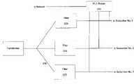
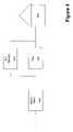
- the typical electric power distribution architectureis illustrated. No filter or other barrier is employed to isolate data from one residence to the next. Using this architecture for a power line communications system, typically a power line signal containing the data will be fed at the transformer. There are four potential problems with this topology for communications.
- the bandwidthis shared between plural subscribers.
- noise from another subscriber using a different type of power line communication system or noise from another subscriber's appliancesmay cause interference.
- subscribers using the same systemcan interact with each other.
- the present inventionprovides isolation between a power line local area network and another network such as a power line wide area network.
- a filter deviceis installed on the power line supplying power to a structure in which a power line local area network is present.
- the example filter devicemay comprise a controller configured to receive a control signal and to cause a switch to activate or deactivate a low pass filter for attenuating the data signals.
- FIG. 1illustrates a conceptual view of a typical electric distribution topology.
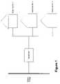
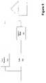
- FIG. 2illustrates a block diagram view of centralized data isolation.
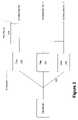
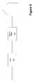
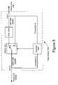
- FIG. 3illustrates a block diagram view of an embodiment of the present invention having isolation before the power meter.
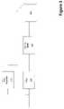
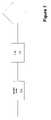
- FIG. 4illustrates a block diagram view of an embodiment of the present invention having isolation after the power meter.
- FIG. 5illustrates a block diagram view of an embodiment of the present invention having isolation bridging the power meter.
- FIG. 6illustrates a block diagram view of an embodiment of the present invention having a LAN only topology with a filter before the meter.
- FIG. 7illustrates a block diagram view of an embodiment of the present invention having a LAN only topology with a filter after the meter.
- FIG. 8illustrates a block diagram of an example embodiment of a filter device, according to the present invention.
- FIG. 9illustrates a block diagram of another example embodiment of a filter device, according to the present invention.
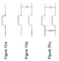
- FIGS. 10 a–cillustrates a example filters that may form part of an embodiment according to the present invention.
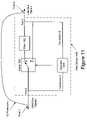
- FIG. 11illustrates a block diagram of an example embodiment of a partially installed filter device, according to the present invention.
- data isolationis accomplished in a centralized manner, in a distributed manner (i.e., at the subscriber), or in a hybrid manner that is a combination of centralized and distributed.
- a systemprovides for network communications isolation in a branch line connecting a subscriber device at a subscriber premises to a network.
- the systemincludes an electric power distribution transformer, a branch line (connected between the transformer and the subscriber's premises), a low pass filter, and a power line communications router.
- the low pass filterconnected in the branch line at a location adjacent the transformer.
- the power line communications routeris connected to the network and coupled to the branch line at a location adjacent the filter, on the subscriber side of the filter.
- the network couplerprovides network communications isolation in a branch line connected to a subscriber premises through an electric power meter.
- the network couplerincludes a low pass filter and a power line communications repeater.
- the low pass filteris coupled to the branch line adjacent to the power meter.
- the power line communications repeateris connected to the branch line across the low pass filter.
- the power line communications repeateris connected across both the low pass filter and the power meter.
- the power line communications repeateris connected across only the low pass filter.
- the low pass filteris disposed either on the subscriber side of the power meter, or on the transformer side of the power meter.
- a network isolatorprovides network communications isolation in a branch line connected to a subscriber premises through an electric power meter.
- the isolationis provided between a network located at the subscriber premises and a transformer connected to the branch line.
- the network isolatorincludes a low pass filter.
- the low pass filteris coupled to the branch line adjacent to the power meter.
- the low pass filteris disposed either on the subscriber side of the power meter, or on the transformer side of the power meter.
- a centralized power line communications (PLC) router 210is illustrated.
- the centralized PLC router 210is connected separately to each branch line, which in turn connects to the subscriber.
- a filter 220passes the high power electricity (100 VAC to 240 VAC) but blocks the power line communications signal.
- This filter 220is implemented using electronic components such as inductors, capacitors and resistors.
- This methodrequires splicing the electric power line and inserting the filter 210 in series with the line 230 .
- datais isolated using a distributed approach.
- a filtersuch as described above
- a power line data repeaterwhich regenerates the data, is connected in parallel with the filtering device.
- This topologyaddresses the noise, interference and security issues. However, the bandwidth is shared between each subscriber connected to the transformer.
- FIG. 3a block diagram view of an embodiment of the present invention having isolation before the power meter 300 is illustrated. This is an implementation according to a distributed topology.
- a PLC repeater 310 and a filter 320are connected in parallel with one another and in series with the power meter 300 .
- the power meter 300is disposed between the subscriber's house 340 and the PLC repeater 310 .
- FIG. 4a block diagram view of an embodiment of the present invention having isolation after the power meter 400 is illustrated.
- a PLC repeater 410 and a filter 420are connected in parallel with one another and in series with the power meter 400 .
- the PLC repeater 410is disposed between the subscriber's house 440 and the power meter 400 .
- FIG. 5a block diagram view of an embodiment of the present invention having isolation bridging the power meter is illustrated.
- a filter 520is connected in series with the power meter 500 , and that series combination is connected in parallel with a PLC repeater 510 .
- Performance according to this embodimentis superior since the electric meter 500 presents some attenuation of the power line communication signals.
- the PLC repeater 510repeats signals across the filter 520 and electric meter 500 . This achieves a better signal-to-noise ratio by avoiding the attenuation that would otherwise be introduced by the electric meter 500 .
- a filtering deviceis placed on the power line adjacent the subscriber's premises. This is useful in cases where an internal Local Area Network (LAN) exists within the premises and access to a Wide Area Network (WAN) in not required. This provides security for the LAN as well as reduces interference from the outside. It also isolates the LAN from the WAN in case a WAN is deployed.
- the filter 610 and the electric meter 620are connected in a serial with one another, with the filter 610 before the electric meter 620 .
- FIG. 7illustrates the filter 710 and the electric meter 720 as being connected in a serial with one another, with the filter 710 placed after the electric meter 720 .
- the arrangement according to both of these illustrated topologiesfunctionally perform the same. However, depending on the deployment one may be easier to implement than the other.
- the WANmay be formed, at least in part (e.g., locally) of a power line communications system that provides access to the Internet for its subscribers.
- a power line communications systemthat provides access to the Internet for its subscribers.
- the power line communications systemmay communicate over all of the low voltage power lines coupled to the distribution transformer, which are collectively referred to herein as the low voltage subnet.
- a Homeplug TM networke.g., Homeplug 1.0, or AV
- other power line LANin a home, office building or other structure may impact the performance of the WAN on that low voltage subnet.
- the power line LAN data signals egressing from the structure via the LV supply power linemay be received by the WAN devices connected to the LV supply power lines of the same distribution transformer such as user devices of subscribers of the PLCS service or power line communications devices external to the home (e.g., coupled to the power line).
- the power line LAN data signalsmay be received by such devices as noise, received as non-decryptable data, or received but not addressed for the WAN device and therefore ignored (e.g., after being demodulated).
- the LAN data signals egressing from the structure on the LV power linemay slow communications between the WAN (e.g., PLCS) devices, reduce the bandwidth available to the WAN on the LV subnet, and/or increase communications errors in the WAN.
- the ingress of WAN data signals from the WAN into the structure over the supply power lineswill slow communications between the power line LAN devices, reduce the bandwidth available on the internal power lines, and/or increase communication errors on the LAN.
- the filter device of the present inventioncan prevent such degradations of both networks.
- the filter device or filter thereofmay be a low pass filter formed of capacitors, inductors, and/or resistors.
- the filter device or filter thereofmay be a toroid filter, which is comprised of one or more magnetically permeable toroids that may be disposed in a housing having a first portion and a second portion that couple together via a hinge.
- the toroidsmay be comprised of a first portion and a second portion with each portion in a respective portion of the housing.
- the housing (and toroid portions therein)is clamped around the power line at an appropriate location as discussed herein.
- An example of such a enclosure for housing such toroidsis provided in U.S.
- a filter device 1500may have a switch 1501 .
- the switch 1501allows the device 1500 to transition between an active (filtering) mode and an inactive (not filtering) mode so that if a power line LAN user wishes to subscribe to or use the WAN (e.g., PLCS), the filter can be “deactivated” simply by actuating the switch 1501 , without the need to uninstall the device 1500 .
- a power line LAN userwishes to subscribe to or use the WAN (e.g., PLCS)
- the filtercan be “deactivated” simply by actuating the switch 1501 , without the need to uninstall the device 1500 .
- the switch 1501may have a first configuration in which the device is in active mode in which the filter 1502 is filtering (i.e., attenuating data signals).
- the switch 1501may have a second configuration in which the device 1500 is in inactive mode in which the filter 1502 is not filtering.
- Placing the device 1500 in inactive modemay comprise changing the value of one or more components that form part of the filter circuitry (e.g., to change the filter characteristics) such via a transistor circuit.
- An inactive modemay alternately be achieved by shunting the data signals, and possibly the power signals, around the filter 1502 as shown in FIG. 8 . In other words, in this embodiment, in the inactive mode the filter 1502 is removed from the path of the data and power.
- the switch 1501may receive an input from a controller 1505 , which may receive an input via a wireless link or via the low voltage power lines to which the filter device 1500 is attached.
- a PLCS network devicesuch as a bypass device mounted near a distribution transformer and communicatively coupled to the low voltage power line(s), may transmit a control signal to the filter device 1500 via the low voltage power line.
- the controller 1505 in the device 1500may provide a signal to the switch 1501 to transition to the appropriate mode or configuration (active or inactive) or to simply toggle (i.e., to switch modes irrespective of the present configuration).
- the control signalmay be transmitted from a power line LAN device in the structure to the filter device 1500 , which is received by the controller 1505 via connection D.
- the usermay wish to isolate the LAN data from the WAN. Consequently, the user may provide an input to a home computer, which responds by executing one or more computer code segments (a computer program) which causes the computer to transmit (or cause a secondary device to transmit) the control signal to the filter device 1500 .
- the switch 1501may comprise a transistor, transistor circuit, a relay, and/or multiple relays.
- the switch 1501 and controller 1505may also be integrated into a single device (e.g., an integrated circuit). Alternately, the switch 1501 may be a manual switch actuated via a user manually.
- the filter device 1500 of FIG. 8may receive a control signal from both a WAN device and a LAN device.
- the signal transmittedmay be any suitable control signal for which the device is configured to receive and respond to (e.g., by activating or deactivating the filter 1502 ).
- the device 1500may or may not send a response such as an acknowledgment.
- the control signal transmittedmay be a internet protocol (IP) packet transmitted according to a Homeplug standard.
- IPinternet protocol
- the device 1500 (and its controller)may further comprise a demodulator (or a full modem chip set) for receiving the signal and processing the control signal.
- the filter devicemay comprise an input filter and amplifier for amplifying and filtering one or more frequency bands in which the control signal may be sent or modulated.
- the filter devicemay comprise a network address (WAN address, LAN address, or both) and only respond if the address in the received control signal corresponds to the address of the filter device 1500 .
- a network addressWAN address, LAN address, or both
- numerous structuresmay receive power via a separate low voltage supply power line, (all of which may be connected near the transformer)
- a separate filter device 1500may be installed on each low voltage power line supplying power to the plurality of structures.
- each filtering devicemay be individually controlled via a local PLCS WAN device (e.g., the PLCS bypass device coupled to the LV power lines) or remotely (e.g., a power line server or other device that transmits the control signal to the filter device 1500 via the Internet and PLCS).
- the control signal sentmay comprise a portion of the frequency band used by the LAN, the WAN, or both.
- the control signalmay comprise a lower frequency pulse or tone in one or more frequencies that are not in the frequency band used by the LAN or WAN.
- the control signalcould comprise a 500 Hz tone for a duration of one second to which the filter device 1500 responds by toggling the filter's mode (inactive or active).
- first and second tones of different frequenciesmay each comprise a control signal indicating a command to activate or deactivate the filter, respectively.
- each filter device 1500may be configured to receive a different frequency, thereby being addressable via use of a particular frequency tone or set of tones. While these example low frequencies are higher than the 60 Hz power signal frequency, they are much lower than the megahertz frequencies used by the Homeplug standard and protocols for other typical broadband communications. If a control signal has a frequency that is also used by the WAN or LAN, the filter device must be able to receive the signal when the filter is active (filtering out that frequency). Consequently, it may be desirable to configure the controller 1505 (that may comprise a receiver) of the filter device 1500 so that it may receive the control signal even when the filter device is in the active mode as in the example embodiment shown in FIG. 8 .
- the embodimentmay be stand alone devices or may be integrated into, or form part of, another device such as a power meter.
- some power metersinclude, or are easily modified to include, a power line modem (e.g., a Homeplug modem), which with appropriate hardware and software and interfacing could act as the controller or the receiver portion of the controller.
- a power line modeme.g., a Homeplug modem
- the low voltage power linetypically includes a neutral conductor and two conductors carrying current (“energized conductors”).
- the two energized conductorstypically carry about 120V alternating current (AC) at a frequency of 60 Hz and are 180 degrees out of phase with each other.
- the high frequency data signalswill often couple from one conductor to another.
- data that is communicated onto one energized conductorwill be present on both energized conductors and perhaps on the neutral conductor as well.
- the amount of couplingis related, in part, to the distance between the conductors, their diameter, and the power and frequency of the signal.
- some PLCS devicese.g., WAN devices external to the structure
- transmit data on both energized conductorse.g., differentially).
- the data signalsoften may be present on both energized conductors of the LV power line and may also be present on the neutral conductor.
- alternate embodimentsmay comprise two or three filter devices in one housing.
- Such an embodimentmay comprise only one controller that actuates a switch in line with each conductor to control the mode and activation of the filter.
- a separate filtering devicemay be installed on each conductor.
- each filtering devicein a separate housing and to form the housing from a conductive material and, perhaps, to conductively connect the conductive housings to ground.
- the housingswould not be connected to the conductors.
- the filter device 1600may comprise a first switch 1601 and first filter 1602 near a first port (e.g., Port X) and a second switch 1603 and second filter 1604 near a second port (e.g., Port Y).
- the filters 1602 and 1604may be separated by a distance D so that there is a gap or space along the conductor providing the power signal path where there are no data signals present.
- Some of the embodiments, for example as illustrated in FIG. 8may have a discontinuity in the path of the data signals.
- the gap of the filter device 1600 in FIG. 9reduces the likelihood of the data signals coupling around the filters 1602 , 1604 .
- the distance D of the gap between the filtersmay be proportional to the wavelength of one or more of the frequencies used by the WAN or LAN.
- the distance Dmay be approximately five percent, ten percent, or twenty percent of the wavelength of the highest frequency used by the power line LAN.
- the filters hereinmay be bi-directional filters to prevent both the ingress and egress of data signals to and from the structure.
- the filter in any of the embodimentsmay be an inductor in series with the power line conductor.
- the filtermay also comprise a capacitor to the ground or neutral conductor.
- the filtersmay comprise an inductor in series with each energized conductor and a first capacitor connecting the first energized conductor to the second energized conductor on a first side of the inductors as shown in FIG. 10 b .
- theremay also be an inductor in series with the neutral and a second capacitor connecting the neutral to the first energized conductor and a third capacitor connecting the neutral to the second energized conductor.
- the filtermay comprise a fourth capacitor coupling the first energized conductor to the second energized conductor on the second side of their inductors as shown in FIG. 10 c .
- the filtersmay comprise a fifth and sixth capacitor connecting the neutral to the first and second energized conductors, respectively.
- the fifth and sixth capacitorsmay be couple to the neutral and energized conductors at the opposite side of their respective inductors to which the first, second, and third capacitors connect.
- the connection of the filter to the neutral (or ground) or other energized conductoris not shown in figures and the filter is not so limited.
- Any suitable filter circuitrymay be used including, but not limited to those described above, a Butterworth low pass filter (which may a first order or second order filter) or other low pass filter or band pass filter. Thus, a first order, second order, third order, or other filter may be used.
- Attenuating a high or moderate percentage of the energy of the data signalsmay be sufficient to eliminate communication problems or increase performance sufficiently—even though some degradation may still occur, albeit less performance degradation (e.g., less frequently, fewer errors, less bandwidth degradation, and/or less latency) than without any attenuation (or only attenuation of a power meter if provided thereby).
- the filter devicesmay be installed anywhere along the LV power line that supplies power to the structure (i.e., the supply power line) such as between 1) the juncture of the supply power line with the supply power line of any of the other structures; and 2) the point at which the supply power line connects to the electric distribution network of the structure (e.g., up to and inside the circuit breaker box).
- the filter devicemay be installed in a circuit breaker box and potentially integrated into the structure's main circuit breaker. Installation may then entail simply replacing the main circuit breaker with a new circuit breaker having the integrated filter device.
- the filter devicesalso may be installed at a mole along an underground low voltage supply power line or very near the juncture of the supply power lines (e.g., and mounted to the utility pole).
- the filter devices of the example embodimentsare in-line with the low voltage supply power line(s). Consequently, installing the filter device could include cutting low voltage power conductor(s), which can be disruptive to electric power customers.
- One method of installing the device without disrupting poweris to first connect a first port of filter device to the low voltage power line. For example and as shown in FIG. 11 , Port X may be electrically connected to the power line at Point J along the power line conductor. Second, Port Y may be electrically connected to the power line conductor at Point K along the power line conductor. Power may now flow through the filter device (and the power line).
- the power linemay be severed somewhere between Point J and Point K (e.g., perhaps near both points), thereby forcing power (and data) to flow through the filter device 1500 .
- the devicemay be installed without disconnecting power from structure. This method of installation may be used with any of the embodiments of the present invention for which the installation method is applicable.
- the filter deviceis disposed in a housing having a first portion and a second portion that are coupled together via a hinge.
- the housingis clamped around the supply power line at an appropriate location.
- the clamping of the housingmay substantially simultaneously connect the filter device and severs the power line conductor(s).
- the connection of the filter devicemay occur slightly before severing of the power line conductor(s) or substantially simultaneously. In either case, the power customer should experience no, or minimal, interruption of electric service.
- the housing of this embodimentmay comprise a severing mechanism (to sever the power line) and a crimping mechanism (to connect the filter device) on each end of the housing. Mechanisms that both cut and crimp connectors onto conductors in one action are well known in the art and therefore a detailed description is not provided herein.
- a PLCSmay provide adequate performance without an attenuator even if competing with the power line LAN for the LV subnet.
- the PLCS network elemente.g., a transformer bypass device
- the PLCS network elementmay perform performance testing to determine if a power line LAN is present in any of the structures coupled to the LV subnet. The performance testing may be accomplished by periodically communicating with a PLCS subscriber and detecting substantial or partial degradations in communication speeds, bandwidth, or increases in error rates.
- the PLCS network devicemay automatically transmit a notification to a central computer (e.g., a power line server described in the incorporated reference) to initiate installation of filter devices in the LV power lines of one or more of the non-PLCS subscribers or on all of the LV power lines coupled to the PLCS network device.
- a central computere.g., a power line server described in the incorporated reference
- the PLCS network devicemay automatically transmit a notification to a central computer (e.g., a power line server) to initiate a marketing campaign to market the PLCS service.
- a central computere.g., a power line server
- the bypass device of the incorporated referencemay be configured to transmit the control signals.
- the signalmay be transmitted through the distribution transformer to the customer location (e.g., with or without a repeater on the low voltage power line).
- the inventionis not limited to a particular PLCS, PLCS architecture, or topology.
Landscapes
- Engineering & Computer Science (AREA)
- Computer Networks & Wireless Communication (AREA)
- Signal Processing (AREA)
- Power Engineering (AREA)
- Cable Transmission Systems, Equalization Of Radio And Reduction Of Echo (AREA)
Abstract
Description
Claims (50)
Priority Applications (2)
| Application Number | Priority Date | Filing Date | Title |
|---|---|---|---|
| US10/899,926US7176786B2 (en) | 2000-01-20 | 2004-07-27 | Method of isolating data in a power line communications network |
| PCT/US2005/026401WO2006014902A2 (en) | 2004-07-27 | 2005-07-26 | Method of isolating data in a power line communications network |
Applications Claiming Priority (3)
| Application Number | Priority Date | Filing Date | Title |
|---|---|---|---|
| US17723700P | 2000-01-20 | 2000-01-20 | |
| US09/765,910US6977578B2 (en) | 2000-01-20 | 2001-01-19 | Method of isolating data in a power line communications network |
| US10/899,926US7176786B2 (en) | 2000-01-20 | 2004-07-27 | Method of isolating data in a power line communications network |
Related Parent Applications (1)
| Application Number | Title | Priority Date | Filing Date |
|---|---|---|---|
| US09/765,910Continuation-In-PartUS6977578B2 (en) | 2000-01-20 | 2001-01-19 | Method of isolating data in a power line communications network |
Publications (2)
| Publication Number | Publication Date |
|---|---|
| US20050007241A1 US20050007241A1 (en) | 2005-01-13 |
| US7176786B2true US7176786B2 (en) | 2007-02-13 |
Family
ID=35787753
Family Applications (1)
| Application Number | Title | Priority Date | Filing Date |
|---|---|---|---|
| US10/899,926Expired - LifetimeUS7176786B2 (en) | 2000-01-20 | 2004-07-27 | Method of isolating data in a power line communications network |
Country Status (2)
| Country | Link |
|---|---|
| US (1) | US7176786B2 (en) |
| WO (1) | WO2006014902A2 (en) |
Cited By (10)
| Publication number | Priority date | Publication date | Assignee | Title |
|---|---|---|---|---|
| US20050254516A1 (en)* | 2000-04-19 | 2005-11-17 | Serconet, Ltd. | Network combining wired and non-wired segments |
| US7333003B1 (en) | 2007-04-24 | 2008-02-19 | Telkonet, Inc. | Power line coupler adapted for use with multiple electric power meters |
| US20080315971A1 (en)* | 2007-06-21 | 2008-12-25 | Radtke William O | Power Line Data Signal Attenuation Device and Method |
| US20090043926A1 (en)* | 2006-05-12 | 2009-02-12 | Texas Instruments Incorporated | Bidirectional data repeater switch |
| US7715534B2 (en) | 2000-03-20 | 2010-05-11 | Mosaid Technologies Incorporated | Telephone outlet for implementing a local area network over telephone lines and a local area network using such outlets |
| US7852874B2 (en) | 1998-07-28 | 2010-12-14 | Mosaid Technologies Incorporated | Local area network of serial intelligent cells |
| US7873058B2 (en) | 2004-11-08 | 2011-01-18 | Mosaid Technologies Incorporated | Outlet with analog signal adapter, a method for use thereof and a network using said outlet |
| US7881462B2 (en) | 2004-02-16 | 2011-02-01 | Mosaid Technologies Incorporated | Outlet add-on module |
| US7990908B2 (en) | 2002-11-13 | 2011-08-02 | Mosaid Technologies Incorporated | Addressable outlet, and a network using the same |
| US8536985B1 (en)* | 2001-07-30 | 2013-09-17 | Imaging Systems Technology, Inc. | Data isolation |
Families Citing this family (23)
| Publication number | Priority date | Publication date | Assignee | Title |
|---|---|---|---|---|
| US7176786B2 (en) | 2000-01-20 | 2007-02-13 | Current Technologies, Llc | Method of isolating data in a power line communications network |
| US7199699B1 (en) | 2002-02-19 | 2007-04-03 | Current Technologies, Llc | Facilitating communication with power line communication devices |
| US7132819B1 (en) | 2002-11-12 | 2006-11-07 | Current Technologies, Llc | Floating power supply and method of using the same |
| US9596031B2 (en)* | 2005-03-01 | 2017-03-14 | Alexander Ivan Soto | System and method for a subscriber-powered network element |
| US7414526B2 (en)* | 2005-06-28 | 2008-08-19 | International Broadband Communications, Inc. | Coupling of communications signals to a power line |
| US7319717B2 (en)* | 2005-06-28 | 2008-01-15 | International Broadband Electric Communications, Inc. | Device and method for enabling communications signals using a medium voltage power line |
| US7778514B2 (en)* | 2005-07-15 | 2010-08-17 | International Broadband Electric Communications, Inc. | Coupling of communications signals to a power line |
| US7522812B2 (en)* | 2005-07-15 | 2009-04-21 | International Broadband Electric Communications, Inc. | Coupling of communications signals to a power line |
| US7667344B2 (en)* | 2005-07-15 | 2010-02-23 | International Broadband Electric Communications, Inc. | Coupling communications signals to underground power lines |
| FR2895850A1 (en)* | 2006-01-04 | 2007-07-06 | Canon Res Ct France S A S Soc | Local communication network for transmitting data signals, has set of coupling circuits, where each coupling circuit connects one port of data interconnection unit to segment of electric energy distribution network |
| FR2895851B1 (en)* | 2006-01-04 | 2012-06-01 | Canon Res Ct France S A S | METHOD OF INSULATING DATA SIGNALS IN A POWER DISTRIBUTION NETWORK AND DEVICE FOR CARRYING OUT SAID METHOD |
| TWI334258B (en)* | 2006-12-08 | 2010-12-01 | Delta Networks Inc | Homeplug apparatus and surge protecitng circuit thereof |
| US8819743B2 (en) | 2007-12-19 | 2014-08-26 | Dish Network L.L.C. | Transfer of data related to broadcast programming over a communication network |
| US9337545B2 (en) | 2008-06-20 | 2016-05-10 | Dish Network L.L.C. | Apparatus and systems for mounting an electrical switching device |
| US8780008B2 (en)* | 2008-06-20 | 2014-07-15 | Dish Network L.L.C. | Reinforced mount for an antenna assembly |
| KR101666226B1 (en)* | 2010-03-08 | 2016-10-13 | 엘에스산전 주식회사 | Apparatus for detecting power |
| US8802985B2 (en) | 2011-09-07 | 2014-08-12 | Dish Network L.L.C. | In-wall extension apparatus |
| US9123987B2 (en) | 2012-07-31 | 2015-09-01 | Dish Network L.L.C. | Antenna mounting systems and methods |
| US9584187B2 (en)* | 2012-10-15 | 2017-02-28 | Broadcom Corporation | Non-interruptive filtering of transmission line communications |
| US9356655B2 (en)* | 2014-07-15 | 2016-05-31 | Stmicroelectronics S.R.L. | Method of operating communication networks, corresponding communication network and computer program product |
| HUE046069T2 (en)* | 2015-04-17 | 2020-02-28 | Landis & Gyr Ag | An electricity meter and an adaptor module therefor |
| IL263929A (en)* | 2018-12-24 | 2020-06-30 | S G A Innovations Ltd | Systems, devices, and methods for detecting and/or preventing communication over power lines |
| CN110730019A (en)* | 2019-10-08 | 2020-01-24 | 桂林理工大学 | A Method of Using Active Shielding Technology to Construct PLC Intelligent Micro-communication Network |
Citations (96)
| Publication number | Priority date | Publication date | Assignee | Title |
|---|---|---|---|---|
| US3369078A (en) | 1965-06-28 | 1968-02-13 | Charles R. Stradley | System for transmitting stereophonic signals over electric power lines |
| US3810096A (en) | 1972-09-14 | 1974-05-07 | Integrated Syst Co | Method and system for transmitting data and indicating room status |
| US3911415A (en) | 1973-12-18 | 1975-10-07 | Westinghouse Electric Corp | Distribution network power line carrier communication system |
| US3942170A (en) | 1975-01-31 | 1976-03-02 | Westinghouse Electric Corporation | Distribution network powerline carrier communication system |
| US3942168A (en) | 1975-01-31 | 1976-03-02 | Westinghouse Electric Corporation | Distribution network power line communication system |
| US3944723A (en) | 1974-12-05 | 1976-03-16 | General Electric Company | Station for power line access data system |
| US3964048A (en) | 1974-01-28 | 1976-06-15 | General Public Utilities Corporation | Communicating over power network within a building or other user location |
| US3967264A (en) | 1975-01-31 | 1976-06-29 | Westinghouse Electric Corporation | Distribution network power line communication system including addressable interrogation and response repeater |
| US3973240A (en) | 1974-12-05 | 1976-08-03 | General Electric Company | Power line access data system |
| US3973087A (en) | 1974-12-05 | 1976-08-03 | General Electric Company | Signal repeater for power line access data system |
| US4004257A (en) | 1975-07-09 | 1977-01-18 | Vitek Electronics, Inc. | Transmission line filter |
| US4004110A (en) | 1975-10-07 | 1977-01-18 | Westinghouse Electric Corporation | Power supply for power line carrier communication systems |
| US4057793A (en) | 1975-10-28 | 1977-11-08 | Johnson Raymond E | Current carrier communication system |
| US4060735A (en) | 1976-07-12 | 1977-11-29 | Johnson Controls, Inc. | Control system employing a programmable multiple channel controller for transmitting control signals over electrical power lines |
| US4239940A (en) | 1978-12-26 | 1980-12-16 | Bertrand Dorfman | Carrier current communications system |
| US4250489A (en) | 1978-10-31 | 1981-02-10 | Westinghouse Electric Corp. | Distribution network communication system having branch connected repeaters |
| US4475209A (en) | 1982-04-23 | 1984-10-02 | Westinghouse Electric Corp. | Regenerator for an intrabundle power-line communication system |
| EP0141673A2 (en) | 1983-11-07 | 1985-05-15 | Emlux Limited | Filtering electrical signals |
| US4580276A (en)* | 1983-08-05 | 1986-04-01 | Consultant's Choice Inc. | System and method for transporting data |
| US4599598A (en)* | 1981-09-14 | 1986-07-08 | Matsushita Electric Works, Ltd. | Data transmission system utilizing power line |
| US4638298A (en) | 1985-07-16 | 1987-01-20 | Telautograph Corporation | Communication system having message repeating terminals |
| US4642607A (en) | 1985-08-06 | 1987-02-10 | National Semiconductor Corporation | Power line carrier communications system transformer bridge |
| US4683450A (en) | 1982-07-01 | 1987-07-28 | Feller Ag | Line with distributed low-pass filter section wherein spurious signals are attenuated |
| US4766414A (en) | 1986-06-17 | 1988-08-23 | Westinghouse Electric Corp. | Power line communication interference preventing circuit |
| US4772870A (en) | 1986-11-20 | 1988-09-20 | Reyes Ronald R | Power line communication system |
| US4815106A (en)* | 1986-04-16 | 1989-03-21 | Adaptive Networks, Inc. | Power line communication apparatus |
| US4903006A (en) | 1989-02-16 | 1990-02-20 | Thermo King Corporation | Power line communication system |
| US5066939A (en) | 1989-10-04 | 1991-11-19 | Mansfield Jr Amos R | Method and means of operating a power line carrier communication system |
| US5257006A (en) | 1990-09-21 | 1993-10-26 | Echelon Corporation | Method and apparatus for power line communications |
| US5319634A (en) | 1991-10-07 | 1994-06-07 | Phoenix Corporation | Multiple access telephone extension systems and methods |
| US5355109A (en) | 1992-02-03 | 1994-10-11 | Kitagawa Industries Co., Ltd. | Electric noise absorber |
| GB2293950A (en) | 1994-10-04 | 1996-04-10 | Northern Telecom Ltd | Communications system using power distribution network |
| US5537087A (en) | 1991-08-07 | 1996-07-16 | Mitsubishi Denki Kabushiki Kaisha | Signal discriminator |
| US5684450A (en) | 1992-10-22 | 1997-11-04 | Norweb Plc | Electricity distribution and/or power transmission network and filter for telecommunication over power lines |
| US5726980A (en) | 1995-03-30 | 1998-03-10 | Northern Telecom Limited | Time division duplex communications repeater |
| US5777769A (en) | 1995-12-28 | 1998-07-07 | Lucent Technologies Inc. | Device and method for providing high speed data transfer through a drop line of a power line carrier communication system |
| WO1998033258A2 (en) | 1997-01-28 | 1998-07-30 | Northern Telecom Limited | Power line transmission |
| US5818821A (en) | 1994-12-30 | 1998-10-06 | Intelogis, Inc. | Universal lan power line carrier repeater system and method |
| US5870016A (en) | 1997-02-03 | 1999-02-09 | Eva Cogenics Inc Euaday Division | Power line carrier data transmission systems having signal conditioning for the carrier data signal |
| US5949327A (en) | 1994-08-26 | 1999-09-07 | Norweb Plc | Coupling of telecommunications signals to a balanced power distribution network |
| US5952914A (en) | 1997-09-10 | 1999-09-14 | At&T Corp. | Power line communication systems |
| US5978371A (en) | 1997-03-31 | 1999-11-02 | Abb Power T&D Company Inc. | Communications module base repeater |
| US5994998A (en)* | 1997-05-29 | 1999-11-30 | 3Com Corporation | Power transfer apparatus for concurrently transmitting data and power over data wires |
| GB2347601A (en) | 1998-09-03 | 2000-09-06 | Nor Web Dpl Limited | Communications apparatus with mains filter |
| US6144292A (en) | 1992-10-22 | 2000-11-07 | Norweb Plc | Powerline communications network employing TDMA, FDMA and/or CDMA |
| US6151480A (en) | 1997-06-27 | 2000-11-21 | Adc Telecommunications, Inc. | System and method for distributing RF signals over power lines within a substantially closed environment |
| US6177849B1 (en) | 1998-11-18 | 2001-01-23 | Oneline Ag | Non-saturating, flux cancelling diplex filter for power line communications |
| US6282405B1 (en) | 1992-10-22 | 2001-08-28 | Norweb Plc | Hybrid electricity and telecommunications distribution network |
| US6297729B1 (en) | 1999-03-29 | 2001-10-02 | International Business Machines Corporation | Method and apparatus for securing communications along ac power lines |
| US20010045888A1 (en) | 2000-01-20 | 2001-11-29 | Kline Paul A. | Method of isolating data in a power line communications network |
| US6335672B1 (en) | 1998-12-23 | 2002-01-01 | L.L. Culmat Lp | Holder for ferrite noise suppressor |
| US6373377B1 (en)* | 2000-10-05 | 2002-04-16 | Conexant Systems, Inc. | Power supply with digital data coupling for power-line networking |
| EP1213849A1 (en) | 2000-12-11 | 2002-06-12 | Siemens Aktiengesellschaft | Method and apparatus for data communication over power line network |
| US6417762B1 (en) | 2001-03-30 | 2002-07-09 | Comcircuits | Power line communication system using anti-resonance isolation and virtual earth ground signaling |
| US20020109585A1 (en) | 2001-02-15 | 2002-08-15 | Sanderson Lelon Wayne | Apparatus, method and system for range extension of a data communication signal on a high voltage cable |
| EP1251646A2 (en) | 2001-04-04 | 2002-10-23 | Siemens Aktiengesellschaft | Method for halfduplex transmission of informations between communication devices with repeaters |
| WO2002089352A1 (en) | 2001-04-26 | 2002-11-07 | Power Plus Communications Ag | Device for electrically connecting a modem to an electric network for line-bound transmission of data |
| US20020186699A1 (en) | 2001-06-08 | 2002-12-12 | Kwok Timothy Chung Hing | System and method for providing high-speed communications access over an electrical network |
| US20030052770A1 (en) | 1999-11-15 | 2003-03-20 | Mansfield Amos R. | Fire system implemented with power line communications |
| US20030062990A1 (en) | 2001-08-30 | 2003-04-03 | Schaeffer Donald Joseph | Powerline bridge apparatus |
| WO2003030396A2 (en) | 2001-09-27 | 2003-04-10 | Siemens Aktiengesellschaft | Method for operating a transmission system and transmission system in an energy supply network |
| US20030071719A1 (en) | 2001-10-02 | 2003-04-17 | Crenshaw Ralph E. | Method and apparatus for attaching power line communications to customer premises |
| WO2003039022A1 (en) | 2001-11-01 | 2003-05-08 | Inovatech Limited | Powerline communication system |
| US20030103307A1 (en) | 2000-04-19 | 2003-06-05 | Kauls Dostert | Method and device for conditioning electric installations in buildings for the rapid transmission of data |
| US20030106067A1 (en) | 2001-11-30 | 2003-06-05 | Hoskins Steve J. | Integrated internet protocol (IP) gateway services in an RF cable network |
| US6590493B1 (en) | 2000-12-05 | 2003-07-08 | Nortel Networks Limited | System, device, and method for isolating signaling environments in a power line communication system |
| US6624745B1 (en)* | 2000-05-18 | 2003-09-23 | Advanced Micro Devices, Inc. | Low pass filter for a universal home network on a customer premises european installation bus |
| US20030179080A1 (en) | 2001-12-21 | 2003-09-25 | Mollenkopf James Douglas | Facilitating communication of data signals on electric power systems |
| US20030224784A1 (en) | 2002-05-28 | 2003-12-04 | Amperion, Inc. | Communications system for providing broadband communications using a medium voltage cable of a power system |
| US6667685B2 (en) | 2000-10-31 | 2003-12-23 | Tdk Corporation | Power line noise filter |
| US20040067745A1 (en) | 2002-10-02 | 2004-04-08 | Amperion, Inc. | Method and system for signal repeating in powerline communications |
| US20040085172A1 (en) | 2002-10-17 | 2004-05-06 | Ambient Corporation | Filter for segmenting power lines for communications |
| US6737984B1 (en)* | 1997-08-15 | 2004-05-18 | General Electric Company | Automatic meter reading system using locally communicating utility meters |
| US20040110483A1 (en) | 2002-12-10 | 2004-06-10 | Mollenkopf James Douglas | Power line communication sytem and method |
| US20040135676A1 (en) | 2002-12-10 | 2004-07-15 | Berkman William H. | Power line communication system and method of operating the same |
| US6771775B1 (en) | 1998-08-17 | 2004-08-03 | Ascom Powerline Communications Ag | Arrangement for communicating messages via a low-voltage electricity supply system and adapter |
| US6785532B1 (en) | 1996-08-01 | 2004-08-31 | Nortel Networks Limited | Power line communications |
| US20040178888A1 (en) | 2003-03-14 | 2004-09-16 | Coaxmedia, Inc. | Bi-directional transfer of signals between a power line communication system and a coaxial distribution system |
| US20040196144A1 (en) | 2001-10-02 | 2004-10-07 | Telkonet, Inc. | Method and apparatus for attaching power line communications to customer premises |
| US20040227623A1 (en) | 2003-05-07 | 2004-11-18 | Telkonet, Inc. | Network topology and packet routing method using low voltage power wiring |
| US20040233928A1 (en) | 2003-05-07 | 2004-11-25 | Telkonet, Inc. | Network topology and packet routing method using low voltage power wiring |
| WO2004102868A2 (en) | 2003-05-08 | 2004-11-25 | Current Technologies, Llc | A power line communication device and method of using the same |
| US20040242185A1 (en) | 2003-05-29 | 2004-12-02 | Amperion, Inc. | Method and device for frequency translation in powerline communications |
| US6842459B1 (en) | 2000-04-19 | 2005-01-11 | Serconet Ltd. | Network combining wired and non-wired segments |
| US20050007241A1 (en) | 2000-01-20 | 2005-01-13 | Kline Paul A. | Method of isolating data in a power line communications network |
| US20050046550A1 (en) | 2001-10-02 | 2005-03-03 | Crenshaw Ralph E. | Method and apparatus for attaching power line communications to customer premises |
| US20050057227A1 (en) | 2003-03-12 | 2005-03-17 | Rockwell Daniel J. | Blocking impedance |
| US20050164666A1 (en) | 2002-10-02 | 2005-07-28 | Lang Jack A. | Communication methods and apparatus |
| US6937056B2 (en) | 2000-09-17 | 2005-08-30 | Serconet Ltd. | System and method for transmission-line termination by signal cancellation, and applications thereof |
| US6952159B1 (en) | 2000-05-30 | 2005-10-04 | Ascom Powerline Communications Ag | Coupling device |
| US6956464B2 (en) | 2003-05-14 | 2005-10-18 | Abocom Systems, Inc. | Power apparatus having built-in powerline networking adapter |
| US20050249245A1 (en) | 2004-05-06 | 2005-11-10 | Serconet Ltd. | System and method for carrying a wireless based signal over wiring |
| US20060017324A1 (en) | 2004-07-21 | 2006-01-26 | Advanced Powerline Technologies, Inc. | Communications network using installed electrical power lines |
| US20060034330A1 (en) | 2003-03-17 | 2006-02-16 | Ryuichi Iwamura | Bandwidth management of virtual networks on a shared network |
| US20060072621A1 (en) | 2004-05-12 | 2006-04-06 | Michael Macaluso | Intelligent, self-aware powerline conditioning and communication node |
| US20060139971A1 (en) | 2004-12-28 | 2006-06-29 | Tdk Corporation | Noise suppressor |
- 2004
- 2004-07-27USUS10/899,926patent/US7176786B2/ennot_activeExpired - Lifetime
- 2005
- 2005-07-26WOPCT/US2005/026401patent/WO2006014902A2/enactiveApplication Filing
Patent Citations (104)
| Publication number | Priority date | Publication date | Assignee | Title |
|---|---|---|---|---|
| US3369078A (en) | 1965-06-28 | 1968-02-13 | Charles R. Stradley | System for transmitting stereophonic signals over electric power lines |
| US3810096A (en) | 1972-09-14 | 1974-05-07 | Integrated Syst Co | Method and system for transmitting data and indicating room status |
| US3911415A (en) | 1973-12-18 | 1975-10-07 | Westinghouse Electric Corp | Distribution network power line carrier communication system |
| US3964048A (en) | 1974-01-28 | 1976-06-15 | General Public Utilities Corporation | Communicating over power network within a building or other user location |
| US3944723A (en) | 1974-12-05 | 1976-03-16 | General Electric Company | Station for power line access data system |
| US3973240A (en) | 1974-12-05 | 1976-08-03 | General Electric Company | Power line access data system |
| US3973087A (en) | 1974-12-05 | 1976-08-03 | General Electric Company | Signal repeater for power line access data system |
| US3942170A (en) | 1975-01-31 | 1976-03-02 | Westinghouse Electric Corporation | Distribution network powerline carrier communication system |
| US3942168A (en) | 1975-01-31 | 1976-03-02 | Westinghouse Electric Corporation | Distribution network power line communication system |
| US3967264A (en) | 1975-01-31 | 1976-06-29 | Westinghouse Electric Corporation | Distribution network power line communication system including addressable interrogation and response repeater |
| US4004257A (en) | 1975-07-09 | 1977-01-18 | Vitek Electronics, Inc. | Transmission line filter |
| US4004110A (en) | 1975-10-07 | 1977-01-18 | Westinghouse Electric Corporation | Power supply for power line carrier communication systems |
| US4057793A (en) | 1975-10-28 | 1977-11-08 | Johnson Raymond E | Current carrier communication system |
| US4060735A (en) | 1976-07-12 | 1977-11-29 | Johnson Controls, Inc. | Control system employing a programmable multiple channel controller for transmitting control signals over electrical power lines |
| US4250489A (en) | 1978-10-31 | 1981-02-10 | Westinghouse Electric Corp. | Distribution network communication system having branch connected repeaters |
| US4239940A (en) | 1978-12-26 | 1980-12-16 | Bertrand Dorfman | Carrier current communications system |
| US4599598A (en)* | 1981-09-14 | 1986-07-08 | Matsushita Electric Works, Ltd. | Data transmission system utilizing power line |
| US4475209A (en) | 1982-04-23 | 1984-10-02 | Westinghouse Electric Corp. | Regenerator for an intrabundle power-line communication system |
| US4683450A (en) | 1982-07-01 | 1987-07-28 | Feller Ag | Line with distributed low-pass filter section wherein spurious signals are attenuated |
| US4580276A (en)* | 1983-08-05 | 1986-04-01 | Consultant's Choice Inc. | System and method for transporting data |
| EP0141673A2 (en) | 1983-11-07 | 1985-05-15 | Emlux Limited | Filtering electrical signals |
| US4638298A (en) | 1985-07-16 | 1987-01-20 | Telautograph Corporation | Communication system having message repeating terminals |
| US4642607A (en) | 1985-08-06 | 1987-02-10 | National Semiconductor Corporation | Power line carrier communications system transformer bridge |
| US4815106A (en)* | 1986-04-16 | 1989-03-21 | Adaptive Networks, Inc. | Power line communication apparatus |
| US4766414A (en) | 1986-06-17 | 1988-08-23 | Westinghouse Electric Corp. | Power line communication interference preventing circuit |
| US4772870A (en) | 1986-11-20 | 1988-09-20 | Reyes Ronald R | Power line communication system |
| US4903006A (en) | 1989-02-16 | 1990-02-20 | Thermo King Corporation | Power line communication system |
| US5066939A (en) | 1989-10-04 | 1991-11-19 | Mansfield Jr Amos R | Method and means of operating a power line carrier communication system |
| US5257006A (en) | 1990-09-21 | 1993-10-26 | Echelon Corporation | Method and apparatus for power line communications |
| US5537087A (en) | 1991-08-07 | 1996-07-16 | Mitsubishi Denki Kabushiki Kaisha | Signal discriminator |
| US5319634A (en) | 1991-10-07 | 1994-06-07 | Phoenix Corporation | Multiple access telephone extension systems and methods |
| US5355109A (en) | 1992-02-03 | 1994-10-11 | Kitagawa Industries Co., Ltd. | Electric noise absorber |
| US6282405B1 (en) | 1992-10-22 | 2001-08-28 | Norweb Plc | Hybrid electricity and telecommunications distribution network |
| US5684450A (en) | 1992-10-22 | 1997-11-04 | Norweb Plc | Electricity distribution and/or power transmission network and filter for telecommunication over power lines |
| US6172597B1 (en) | 1992-10-22 | 2001-01-09 | Norweb Plc | Electricity distribution and/or power transmission network and filter for telecommunication over power lines |
| US6144292A (en) | 1992-10-22 | 2000-11-07 | Norweb Plc | Powerline communications network employing TDMA, FDMA and/or CDMA |
| US5949327A (en) | 1994-08-26 | 1999-09-07 | Norweb Plc | Coupling of telecommunications signals to a balanced power distribution network |
| GB2293950A (en) | 1994-10-04 | 1996-04-10 | Northern Telecom Ltd | Communications system using power distribution network |
| US5818821A (en) | 1994-12-30 | 1998-10-06 | Intelogis, Inc. | Universal lan power line carrier repeater system and method |
| US5726980A (en) | 1995-03-30 | 1998-03-10 | Northern Telecom Limited | Time division duplex communications repeater |
| US5777769A (en) | 1995-12-28 | 1998-07-07 | Lucent Technologies Inc. | Device and method for providing high speed data transfer through a drop line of a power line carrier communication system |
| US6785532B1 (en) | 1996-08-01 | 2004-08-31 | Nortel Networks Limited | Power line communications |
| WO1998033258A2 (en) | 1997-01-28 | 1998-07-30 | Northern Telecom Limited | Power line transmission |
| US5870016A (en) | 1997-02-03 | 1999-02-09 | Eva Cogenics Inc Euaday Division | Power line carrier data transmission systems having signal conditioning for the carrier data signal |
| US5978371A (en) | 1997-03-31 | 1999-11-02 | Abb Power T&D Company Inc. | Communications module base repeater |
| US5994998A (en)* | 1997-05-29 | 1999-11-30 | 3Com Corporation | Power transfer apparatus for concurrently transmitting data and power over data wires |
| US6151480A (en) | 1997-06-27 | 2000-11-21 | Adc Telecommunications, Inc. | System and method for distributing RF signals over power lines within a substantially closed environment |
| US6737984B1 (en)* | 1997-08-15 | 2004-05-18 | General Electric Company | Automatic meter reading system using locally communicating utility meters |
| US5952914A (en) | 1997-09-10 | 1999-09-14 | At&T Corp. | Power line communication systems |
| US6771775B1 (en) | 1998-08-17 | 2004-08-03 | Ascom Powerline Communications Ag | Arrangement for communicating messages via a low-voltage electricity supply system and adapter |
| GB2347601A (en) | 1998-09-03 | 2000-09-06 | Nor Web Dpl Limited | Communications apparatus with mains filter |
| US20020075097A1 (en) | 1998-09-03 | 2002-06-20 | Paul A. Brown | Filter |
| US6177849B1 (en) | 1998-11-18 | 2001-01-23 | Oneline Ag | Non-saturating, flux cancelling diplex filter for power line communications |
| US6335672B1 (en) | 1998-12-23 | 2002-01-01 | L.L. Culmat Lp | Holder for ferrite noise suppressor |
| US6297729B1 (en) | 1999-03-29 | 2001-10-02 | International Business Machines Corporation | Method and apparatus for securing communications along ac power lines |
| US20030052770A1 (en) | 1999-11-15 | 2003-03-20 | Mansfield Amos R. | Fire system implemented with power line communications |
| US20060132299A1 (en) | 1999-11-15 | 2006-06-22 | Ge Security, Inc. | Power line communication system with system member identification |
| US20050128057A1 (en) | 1999-11-15 | 2005-06-16 | Mansfield Amos R. | Preventing unintended communication among power line communication devices associated with different premises power distribution lines of an electric power distribution system |
| US20010045888A1 (en) | 2000-01-20 | 2001-11-29 | Kline Paul A. | Method of isolating data in a power line communications network |
| US6977578B2 (en) | 2000-01-20 | 2005-12-20 | Current Technologies, Llc | Method of isolating data in a power line communications network |
| US20050007241A1 (en) | 2000-01-20 | 2005-01-13 | Kline Paul A. | Method of isolating data in a power line communications network |
| US20030103307A1 (en) | 2000-04-19 | 2003-06-05 | Kauls Dostert | Method and device for conditioning electric installations in buildings for the rapid transmission of data |
| US6842459B1 (en) | 2000-04-19 | 2005-01-11 | Serconet Ltd. | Network combining wired and non-wired segments |
| US6624745B1 (en)* | 2000-05-18 | 2003-09-23 | Advanced Micro Devices, Inc. | Low pass filter for a universal home network on a customer premises european installation bus |
| US6952159B1 (en) | 2000-05-30 | 2005-10-04 | Ascom Powerline Communications Ag | Coupling device |
| US6937056B2 (en) | 2000-09-17 | 2005-08-30 | Serconet Ltd. | System and method for transmission-line termination by signal cancellation, and applications thereof |
| US6373377B1 (en)* | 2000-10-05 | 2002-04-16 | Conexant Systems, Inc. | Power supply with digital data coupling for power-line networking |
| US6667685B2 (en) | 2000-10-31 | 2003-12-23 | Tdk Corporation | Power line noise filter |
| US6590493B1 (en) | 2000-12-05 | 2003-07-08 | Nortel Networks Limited | System, device, and method for isolating signaling environments in a power line communication system |
| EP1213849A1 (en) | 2000-12-11 | 2002-06-12 | Siemens Aktiengesellschaft | Method and apparatus for data communication over power line network |
| US20020109585A1 (en) | 2001-02-15 | 2002-08-15 | Sanderson Lelon Wayne | Apparatus, method and system for range extension of a data communication signal on a high voltage cable |
| US6417762B1 (en) | 2001-03-30 | 2002-07-09 | Comcircuits | Power line communication system using anti-resonance isolation and virtual earth ground signaling |
| EP1251646A2 (en) | 2001-04-04 | 2002-10-23 | Siemens Aktiengesellschaft | Method for halfduplex transmission of informations between communication devices with repeaters |
| WO2002089352A1 (en) | 2001-04-26 | 2002-11-07 | Power Plus Communications Ag | Device for electrically connecting a modem to an electric network for line-bound transmission of data |
| US20020186699A1 (en) | 2001-06-08 | 2002-12-12 | Kwok Timothy Chung Hing | System and method for providing high-speed communications access over an electrical network |
| US20030062990A1 (en) | 2001-08-30 | 2003-04-03 | Schaeffer Donald Joseph | Powerline bridge apparatus |
| WO2003030396A2 (en) | 2001-09-27 | 2003-04-10 | Siemens Aktiengesellschaft | Method for operating a transmission system and transmission system in an energy supply network |
| US20050046550A1 (en) | 2001-10-02 | 2005-03-03 | Crenshaw Ralph E. | Method and apparatus for attaching power line communications to customer premises |
| US20030071719A1 (en) | 2001-10-02 | 2003-04-17 | Crenshaw Ralph E. | Method and apparatus for attaching power line communications to customer premises |
| US20040196144A1 (en) | 2001-10-02 | 2004-10-07 | Telkonet, Inc. | Method and apparatus for attaching power line communications to customer premises |
| US6975212B2 (en) | 2001-10-02 | 2005-12-13 | Telkonet Communications, Inc. | Method and apparatus for attaching power line communications to customer premises |
| WO2003039022A1 (en) | 2001-11-01 | 2003-05-08 | Inovatech Limited | Powerline communication system |
| US20030106067A1 (en) | 2001-11-30 | 2003-06-05 | Hoskins Steve J. | Integrated internet protocol (IP) gateway services in an RF cable network |
| US20030179080A1 (en) | 2001-12-21 | 2003-09-25 | Mollenkopf James Douglas | Facilitating communication of data signals on electric power systems |
| US20030224784A1 (en) | 2002-05-28 | 2003-12-04 | Amperion, Inc. | Communications system for providing broadband communications using a medium voltage cable of a power system |
| WO2004017621A1 (en) | 2002-08-16 | 2004-02-26 | Telkonet Communications, Inc. | Method and apparatus for attaching power line communications to customer premises |
| US20040067745A1 (en) | 2002-10-02 | 2004-04-08 | Amperion, Inc. | Method and system for signal repeating in powerline communications |
| US20050164666A1 (en) | 2002-10-02 | 2005-07-28 | Lang Jack A. | Communication methods and apparatus |
| US7005943B2 (en) | 2002-10-17 | 2006-02-28 | Ambient Corporation | Filter for segmenting power lines for communications |
| US20040085172A1 (en) | 2002-10-17 | 2004-05-06 | Ambient Corporation | Filter for segmenting power lines for communications |
| US20040135676A1 (en) | 2002-12-10 | 2004-07-15 | Berkman William H. | Power line communication system and method of operating the same |
| US20040110483A1 (en) | 2002-12-10 | 2004-06-10 | Mollenkopf James Douglas | Power line communication sytem and method |
| US20050057227A1 (en) | 2003-03-12 | 2005-03-17 | Rockwell Daniel J. | Blocking impedance |
| US20040178888A1 (en) | 2003-03-14 | 2004-09-16 | Coaxmedia, Inc. | Bi-directional transfer of signals between a power line communication system and a coaxial distribution system |
| US20060034330A1 (en) | 2003-03-17 | 2006-02-16 | Ryuichi Iwamura | Bandwidth management of virtual networks on a shared network |
| US20040227623A1 (en) | 2003-05-07 | 2004-11-18 | Telkonet, Inc. | Network topology and packet routing method using low voltage power wiring |
| US20040233928A1 (en) | 2003-05-07 | 2004-11-25 | Telkonet, Inc. | Network topology and packet routing method using low voltage power wiring |
| WO2004102868A2 (en) | 2003-05-08 | 2004-11-25 | Current Technologies, Llc | A power line communication device and method of using the same |
| US6956464B2 (en) | 2003-05-14 | 2005-10-18 | Abocom Systems, Inc. | Power apparatus having built-in powerline networking adapter |
| US20040242185A1 (en) | 2003-05-29 | 2004-12-02 | Amperion, Inc. | Method and device for frequency translation in powerline communications |
| US20050249245A1 (en) | 2004-05-06 | 2005-11-10 | Serconet Ltd. | System and method for carrying a wireless based signal over wiring |
| US20060072621A1 (en) | 2004-05-12 | 2006-04-06 | Michael Macaluso | Intelligent, self-aware powerline conditioning and communication node |
| US20060017324A1 (en) | 2004-07-21 | 2006-01-26 | Advanced Powerline Technologies, Inc. | Communications network using installed electrical power lines |
| US20060139971A1 (en) | 2004-12-28 | 2006-06-29 | Tdk Corporation | Noise suppressor |
Non-Patent Citations (8)
| Title |
|---|
| "Centralized Commerical Building Applications with the Lonworks (R) PLT-21 Power Line Transceiver", Lonworks Engineering Bulletin, Echelon, Apr. 1997, pp. 1-22. |
| "Signalling on Low-Voltage Electrical Installations in the Frequency Band 3kHz to 148.5kHz-Part 4: Filters at the Interface of the Indoor and Outdoor Electricity Network", CLC SC 105A(Secratariat) May 1992, 62, 1-11. |
| EMETCON Automated Distribution System, ABB Power T & D Company, Inc., Jan. 1990, Raleigh, North Carolina, No B-919A, 14 pages. |
| Lim, C.K. et al., "Development of a Test Bed for High-Speed Power Line Communications", School of Electrical and Electronic Engineering, Nanyang Technological University, Singapore, IEEE, 2000, 451-456. |
| LONWORKS Engineering Bulletin, "Demand Side Management with LONWORKS(R) Power Line Transceivers," Dec. 1996, 36 pages. |
| Outlook Conference 2004: Amperion Deployment Overview, Primen Conference, May 7, 2004, 10 pages. |
| Patent Abstracts of Japan, Japanese Publication No. 10200544 A2, published Jul. 31, 1998, (Matsushita Electric Works, LTD). |
| Sado, WN. et al., "Personal Communication on Residential Power Lines- Assessment of Channel Parameters", Nov. 6-10, 1995, IEEE532-537. |
Cited By (24)
| Publication number | Priority date | Publication date | Assignee | Title |
|---|---|---|---|---|
| US8867523B2 (en) | 1998-07-28 | 2014-10-21 | Conversant Intellectual Property Management Incorporated | Local area network of serial intelligent cells |
| US7852874B2 (en) | 1998-07-28 | 2010-12-14 | Mosaid Technologies Incorporated | Local area network of serial intelligent cells |
| US8908673B2 (en) | 1998-07-28 | 2014-12-09 | Conversant Intellectual Property Management Incorporated | Local area network of serial intelligent cells |
| US8885660B2 (en) | 1998-07-28 | 2014-11-11 | Conversant Intellectual Property Management Incorporated | Local area network of serial intelligent cells |
| US8885659B2 (en) | 1998-07-28 | 2014-11-11 | Conversant Intellectual Property Management Incorporated | Local area network of serial intelligent cells |
| US7978726B2 (en) | 1998-07-28 | 2011-07-12 | Mosaid Technologies Incorporated | Local area network of serial intelligent cells |
| US7715534B2 (en) | 2000-03-20 | 2010-05-11 | Mosaid Technologies Incorporated | Telephone outlet for implementing a local area network over telephone lines and a local area network using such outlets |
| US8363797B2 (en) | 2000-03-20 | 2013-01-29 | Mosaid Technologies Incorporated | Telephone outlet for implementing a local area network over telephone lines and a local area network using such outlets |
| US8855277B2 (en) | 2000-03-20 | 2014-10-07 | Conversant Intellectual Property Managment Incorporated | Telephone outlet for implementing a local area network over telephone lines and a local area network using such outlets |
| US7876767B2 (en) | 2000-04-19 | 2011-01-25 | Mosaid Technologies Incorporated | Network combining wired and non-wired segments |
| US8867506B2 (en) | 2000-04-19 | 2014-10-21 | Conversant Intellectual Property Management Incorporated | Network combining wired and non-wired segments |
| US8873586B2 (en) | 2000-04-19 | 2014-10-28 | Conversant Intellectual Property Management Incorporated | Network combining wired and non-wired segments |
| US20050254516A1 (en)* | 2000-04-19 | 2005-11-17 | Serconet, Ltd. | Network combining wired and non-wired segments |
| US8982904B2 (en) | 2000-04-19 | 2015-03-17 | Conversant Intellectual Property Management Inc. | Network combining wired and non-wired segments |
| US8848725B2 (en) | 2000-04-19 | 2014-09-30 | Conversant Intellectual Property Management Incorporated | Network combining wired and non-wired segments |
| US8536985B1 (en)* | 2001-07-30 | 2013-09-17 | Imaging Systems Technology, Inc. | Data isolation |
| US7990908B2 (en) | 2002-11-13 | 2011-08-02 | Mosaid Technologies Incorporated | Addressable outlet, and a network using the same |
| US7881462B2 (en) | 2004-02-16 | 2011-02-01 | Mosaid Technologies Incorporated | Outlet add-on module |
| US7873058B2 (en) | 2004-11-08 | 2011-01-18 | Mosaid Technologies Incorporated | Outlet with analog signal adapter, a method for use thereof and a network using said outlet |
| US7822890B2 (en)* | 2006-05-12 | 2010-10-26 | Texas Instruments Incorporated | Bidirectional data repeater switch |
| US20090043926A1 (en)* | 2006-05-12 | 2009-02-12 | Texas Instruments Incorporated | Bidirectional data repeater switch |
| US7333003B1 (en) | 2007-04-24 | 2008-02-19 | Telkonet, Inc. | Power line coupler adapted for use with multiple electric power meters |
| US7714682B2 (en) | 2007-06-21 | 2010-05-11 | Current Technologies, Llc | Power line data signal attenuation device and method |
| US20080315971A1 (en)* | 2007-06-21 | 2008-12-25 | Radtke William O | Power Line Data Signal Attenuation Device and Method |
Also Published As
| Publication number | Publication date |
|---|---|
| WO2006014902A2 (en) | 2006-02-09 |
| WO2006014902A3 (en) | 2006-04-27 |
| US20050007241A1 (en) | 2005-01-13 |
Similar Documents
| Publication | Publication Date | Title |
|---|---|---|
| US7176786B2 (en) | Method of isolating data in a power line communications network | |
| US7259657B2 (en) | Multi-subnet power line communications system and method | |
| US6977578B2 (en) | Method of isolating data in a power line communications network | |
| US20060255930A1 (en) | Power line communications system and method | |
| US20090085726A1 (en) | Power Line Communications Coupling Device and Method | |
| US6965302B2 (en) | Power line communication system and method of using the same | |
| US7450001B2 (en) | Power line communications system and method | |
| US6998962B2 (en) | Power line communication apparatus and method of using the same | |
| US7796025B2 (en) | Power line communication device and method | |
| US6980091B2 (en) | Power line communication system and method of operating the same | |
| US7301440B2 (en) | Power line communication system and method | |
| US7598844B2 (en) | Power line communications module and method | |
| US7075414B2 (en) | Device and method for communicating data signals through multiple power line conductors | |
| EA006177B1 (en) | Inductive coupling of a data signal to a power transmission cable | |
| CA2515560A1 (en) | A surface wave power line communications system and method | |
| WO2007011516A1 (en) | Coupling communications signals to underground power lines | |
| US8242622B2 (en) | Method and system for communicating over neutral power lines | |
| WO2006012681A1 (en) | Method and device for power line head-end data transmission |
Legal Events
| Date | Code | Title | Description |
|---|---|---|---|
| AS | Assignment | Owner name:CURRENT TECHNOLOGIES, LLC, MARYLAND Free format text:ASSIGNMENT OF ASSIGNORS INTEREST;ASSIGNOR:KLINE, PAUL A.;REEL/FRAME:015789/0332 Effective date:20040812 | |
| AS | Assignment | Owner name:CURRENT TECHNOLOGIES, LLC, MARYLAND Free format text:ASSIGNMENT OF ASSIGNORS INTEREST;ASSIGNOR:BERKMAN, WILLIAM H.;REEL/FRAME:016990/0458 Effective date:20050815 | |
| STCF | Information on status: patent grant | Free format text:PATENTED CASE | |
| CC | Certificate of correction | ||
| AS | Assignment | Owner name:AP CURRENT HOLDINGS, LLC, PENNSYLVANIA Free format text:SECURITY AGREEMENT;ASSIGNOR:CURRENT TECHNOLOGIES, LLC;REEL/FRAME:020518/0001 Effective date:20080129 Owner name:AP CURRENT HOLDINGS, LLC,PENNSYLVANIA Free format text:SECURITY AGREEMENT;ASSIGNOR:CURRENT TECHNOLOGIES, LLC;REEL/FRAME:020518/0001 Effective date:20080129 | |
| AS | Assignment | Owner name:CURRENT TECHNOLOGIES, LLC, MARYLAND Free format text:RELEASE BY SECURED PARTY;ASSIGNOR:AP CURRENT HOLDINGS, LLC;REEL/FRAME:021096/0131 Effective date:20080516 Owner name:CURRENT TECHNOLOGIES, LLC,MARYLAND Free format text:RELEASE BY SECURED PARTY;ASSIGNOR:AP CURRENT HOLDINGS, LLC;REEL/FRAME:021096/0131 Effective date:20080516 | |
| FPAY | Fee payment | Year of fee payment:4 | |
| FPAY | Fee payment | Year of fee payment:8 | |
| SULP | Surcharge for late payment | Year of fee payment:7 | |
| MAFP | Maintenance fee payment | Free format text:PAYMENT OF MAINTENANCE FEE, 12TH YR, SMALL ENTITY (ORIGINAL EVENT CODE: M2553) Year of fee payment:12 |