US7175630B2 - Bone cutting template and method of use - Google Patents
Bone cutting template and method of useDownload PDFInfo
- Publication number
- US7175630B2 US7175630B2US10/357,279US35727903AUS7175630B2US 7175630 B2US7175630 B2US 7175630B2US 35727903 AUS35727903 AUS 35727903AUS 7175630 B2US7175630 B2US 7175630B2
- Authority
- US
- United States
- Prior art keywords
- datum
- guide
- anterior
- posterior
- femur
- Prior art date
- Legal status (The legal status is an assumption and is not a legal conclusion. Google has not performed a legal analysis and makes no representation as to the accuracy of the status listed.)
- Expired - Fee Related, expires
Links
- 238000000034methodMethods0.000titleclaimsabstractdescription20
- 210000000988bone and boneAnatomy0.000titledescription17
- 210000003127kneeAnatomy0.000claimsabstractdescription14
- 238000001356surgical procedureMethods0.000claimsabstractdescription9
- 210000000629knee jointAnatomy0.000claimsabstractdescription8
- 210000000689upper legAnatomy0.000claimsdescription38
- 238000013519translationMethods0.000claimsdescription7
- 210000004872soft tissueAnatomy0.000claimsdescription4
- 239000007943implantSubstances0.000abstractdescription6
- 238000011883total knee arthroplastyMethods0.000abstract1
- 238000013459approachMethods0.000description5
- 238000011882arthroplastyMethods0.000description3
- 238000004513sizingMethods0.000description3
- 230000000007visual effectEffects0.000description2
- 238000004891communicationMethods0.000description1
- 238000003780insertionMethods0.000description1
- 230000037431insertionEffects0.000description1
- 230000002452interceptive effectEffects0.000description1
- 238000002324minimally invasive surgeryMethods0.000description1
Images


Classifications
- A—HUMAN NECESSITIES
- A61—MEDICAL OR VETERINARY SCIENCE; HYGIENE
- A61B—DIAGNOSIS; SURGERY; IDENTIFICATION
- A61B17/00—Surgical instruments, devices or methods
- A61B17/14—Surgical saws
- A61B17/15—Guides therefor
- A61B17/154—Guides therefor for preparing bone for knee prosthesis
- A61B17/155—Cutting femur
Definitions
- the present inventionrelates to methods and instruments for performing bone surgery.
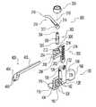
- FIG. 1is an exploded perspective view of an illustrative femoral anterior/posterior sizer according to the present invention.
- FIG. 2is a side elevation view of the sizer of FIG. 1 mounted on a bone.
- FIG. 3is a front elevation view of the sizer of FIG. 1 mounted on a bone.
- FIG. 4is a front elevation view of an illustrative femoral finishing guide according to the present invention being mounted on a bone.
- FIG. 5is a side elevation view of the finishing guide of FIG. 4 mounted on a bone.
- the present inventionrelates to methods and instruments for performing bone surgery.
- an incisionis made into the knee joint to expose the bones comprising the joint.
- Cutting guidesare then used to guide the removal of the articular surfaces that are to be replaced.
- a femoral finishing guideis used to guide a cutter to make the final cuts to prepare the femur to receive a prosthetic implant.
- the present instruments and methodare generally suitable for knee joint surgery. Furthermore, they include features that make them suitable for performing a minimally invasive knee surgery in which a smaller than normal incision is made and oriented to least disturb the soft tissues supporting the knee joint.
- FIGS. 1–3depict an anterior/posterior (AP) sizer for knee arthroplasty.
- APanterior/posterior
- the A/P sizercomprises a base 100 , a slide 200 , a boom assembly 300 , and a reference rail 400 .
- the base 100includes a flat, plate-like body having a proximal face 112 , a distal face 114 and medial 104 , lateral 106 , anterior 108 , and posterior 110 sides.
- the proximal face 112forms a distal reference surface for indexing against the cut distal surface 120 of a femur 122 .
- a pair of feet 116is attached to the base adjacent the posterior side and projects proximally.
- the feet 116include posterior reference surfaces 118 perpendicular to the distal reference surface and facing anteriorly to index against the posterior femoral condyles 124 .
- the base 100includes a plurality of fixation holes 126 extending from the proximal face 112 to the distal face 114 adjacent the medial side 104 of the base 100 .
- the exemplary fixation holes 126are sized to receive a 1 ⁇ 8 inch fixation pin to hold the base 100 in place against the cut distal femur 120 .
- a riser 128is formed on the distal face of the base 100 and extends anteriorly beyond the anterior side 108 of the base 100 .
- the riserincludes a slide receiving channel 130 extending from the anterior end 132 of the riser posteriorly.
- the channel 130has a dovetail cross section to prevent rotation or proximal-distal translation of like-shaped members inserted into the passageway, while allowing anterior-posterior translation.
- a cut out window 134 adjacent the anterior end 132 of the riserpermits viewing into the channel 130 .
- Pointer 136 formed on the side of the window 134provides a convenient reference point.
- a ball detent 138is mounted in a bore in communication with the channel 130 adjacent the anterior end 132 of the riser.
- the riser 128is offset medially so that the lateral edge 140 of the riser is aligned with the center of the base 100 .
- a pair of threaded handle receiving openings 142are formed in the riser at an angle facing medially and distally.
- the sliding portion 202is received in the slide receiving channel 130 of the base 100 for anterior-posterior translation.
- the reference channel 208angles downwardly from medial to lateral at an angle of approximately 3° relative to the posterior reference surfaces 118 .
- the ball detent 138is biased against the side of the sliding portion 202 to create a frictional force that helps to maintain the slide in a user selected position while permitting easy readjustment.
- the indicia 210are viewable through the window 134 relative to the pointer 136 .
- the boom assembly 300comprises a boom base 302 , a boom 310 , and a boom retaining nut 320 .
- the boom base 302comprises a shaft having a boom receiving end 304 , a mounting end 306 , and a raised annular portion 308 between the two ends.
- the mounting end 306includes a ball detent 305 biased radially outwardly.
- the boom 310comprises a collar 312 having a cylindrical through bore 314 and an arm 316 extending from the collar to a tip 318 .
- the tip 318is located radially outwardly and downwardly relative to the collar.
- the boom 310is received on the boom base 302 with the receiving end 304 engaging the bore 314 and the collar 312 abutting the annular portion 308 .
- the boom retaining nut 320threads onto receiving end 304 to hold the assembly together.
- the boom assembly 300is received on the slide 200 with the mounting end 306 engaging the slide collar bore 214 and the annular portion 308 abutting the slide collar 212 .
- the ball detent 305extends below the slide collar and in contact with the lower edge of the slide collar 212 to bias the boom assembly 300 downwardly and releasably lock it in place.
- the boom tip 318is a predetermined fixed distance from the reference channel 208 .
- the distance between the boom tip 318 and the posterior reference surface 118is indicated by the particular one of the slide indicia 210 that is aligned with the pointer 136 in the base window 134 .
- the reference extensions 204 , 206 and the channel 208are located at a corresponding known distance from the posterior reference surface 118 .
- the reference rail 400comprises a generally L-shaped body having a guide rail 402 and a rail mounting base 404 .
- the guide rail 402comprises an elongate bar of rectangular cross section. Alternatively, the bar could be round, dovetail shaped, or of other suitable shape.
- the rail mounting base 404includes fixation holes 406 extending through it for receiving fixation pins to hold the rail 400 on a bone.
- the guide rail 402is receivable in close fitting, sliding relationship within the reference channel 208 of the slide 200 .
- FIGS. 4–5depict an illustrative cut block in the form of a femoral finishing guide 500 .
- the femoral finishing guide 500comprises a slab-like body having a proximal face 502 , a distal face 504 , and medial 506 , lateral 508 , anterior 510 , and posterior 512 sides.
- the proximal face 502forms a distal reference surface for indexing against the cut distal surface 120 of a femur 122 .
- the guide 500includes a variety of small 514 and large 516 fixation holes to receive fasteners to secure the guide 500 to the cut distal surface 120 .
- Fastenersinclude a variety of designs as known in the art such as pins and screws.
- the guide 500further includes cutter guides to guide a cutter to make femoral box cuts to prepare the femur to receive a femoral implant.
- the cutter guidescomprise saw blade slots for guiding a saw blade.
- An anterior cut slot 518guides a saw blade generally proximal-distally to form a flat surface 520 on the anterior femur.
- Posterior cut slots 522guide a saw blade generally proximal-distally to form flat surfaces 524 on the poster aspects of the femoral condyles.
- Anterior 526 and posterior 528 chamfer cut slotsguide a saw blade to form anterior 530 and posterior 532 chambers between the distal cut surface 120 and the anterior 520 and posterior 524 surfaces respectively.
- a trochlear cut slot 534guides a saw blade to form a trochlear recess.
- the proximal face 502 of the cut guideincludes a rail receiving channel 536 having a cross sectional shape to allow it to receive the guide rail 402 in close fitting, sliding relationship.
- the A/P sizeris used to determine the size of the distal femur for implant selection purposes and to create a datum on the distal femur to be used to orient subsequent bone cuts made with the femoral finishing guide.
- the sizer base 100is positioned with the distal reference surface 112 against the cut distal femur 120 .
- the baseis slid anteriorly until the posterior reference surfaces 118 contact the posterior condyles 124 to align the base with the plane containing the posterior most aspects of the posterior condyles 124 and perpendicular to the distal cut surface 120 .
- a handlecan be screwed into one of the handle openings 142 .
- Fastenerscan be placed through the fixation holes 126 to hold the base in position.
- the two handle openings 142 and plurality of fixation holes 126allow the handle and fasteners to be positioned for effective use without interfering with one another.
- the reference channel 208moves with the boom 310 and slide 200 , it is positioned at a predetermined A/P position relative to the posterior reference surface 118 corresponding to the indicated size. If the surgeon determines that a size adjustment should be made, e.g. if the size falls between two indicia or for other clinical reasons, he would reposition the boom 310 and slide 200 so that the desired size indicium is aligned with the pointer 136 . The reference channel 208 will now overlie the bone at a position corresponding to the adjusted size. However, the boom tip 318 prevents sizing the femur too small, which could position subsequent cuts too far posteriorly and notch the anterior cortex.
- the femoral finishing guide 500is now engaged with the guide rail 402 .
- the rail receiving channel 536engages the guide rail 402 to orient the guide 500 in the desired A/P position and external rotation and further to allow medial-lateral (M/L) translation of the finishing guide 500 independent of the A/P position and external rotation.
- the finishing guide 500is placed in the desired M/L position and secured with fasteners through one or more of the guide fixation holes 514 , 516 .
- the guide rail 402is then removed from the bone leaving the finishing guide 500 in place. Additional fasteners may now be placed in any holes that were obstructed by the guide rail 402 if desired.
- a saw bladeis guided through the saws slots to cut the distal femur to receive an implant.
- the external rotation of the guide rail 402can be established by leaving the A/P sizer loose and rotating it and the guide rail 402 so that the guide rail 402 is parallel to an axis extending through the medial and lateral epicondyles.
- external rotationcan be established by orienting the guide rail 402 perpendicular to the A/P axis of the distal femur.
- the alternative embodiment of an A/P sizer 600 shown in FIG. 6facilitates these alternative techniques.
- the A/P sizer 600is generally similar in layout and function to the A/P sizer of FIGS. 1–3 .
- the base 602includes an anterior side 604 that slopes downwardly from medial to lateral.
- the angle of the anterior side 604is approximately the same as the epicondylar axis 606 extending between the medial 608 and lateral 610 femoral epicondyles of the average human femur. This sloping anterior side 604 thus serves as a convenient visual alignment reference for those surgeons who want to orient the guide rail parallel to the epicondylar axis 606 .
- the base 602also includes a riser 612 having at least one side 614 that is parallel to the A/P axis of the average human femur.
- the A/P axisis generally perpendicular to the epicondylar axis and so the side 614 of the riser is made perpendicular to the anterior side 604 .
- This angled side 614thus serves as a convenient visual alignment reference for those surgeons who want to orient the guide rail parallel to the A/P axis.
- the exemplary A/P sizer guide and femoral finishing guide embodiments of FIGS. 1–6include features that are particularly well suited for minimally invasive surgical approaches to knee arthroplasty. These illustrative embodiments are adapted for a left medial minimally invasive surgical approach to the knee. In this approach, a small incision is made on the medial side of the knee. The base 100 is slipped into the incision from medial to lateral, lateral side 106 first. The low proximal-distal profile and medially offset riser facilitate this insertion. Once in place, the lateral side 106 is hidden from view by the overlying soft tissues and is difficult to access. The medial side 104 is more accessible.
- the medial location and medial-distal orientation of the handle receiving openings 142allow access through the medial incision to engage and disengage a handle and permit the handle to project through the small, medial incision.
- the medial placement of the fixation holespermits access through the incision for the placement of fasteners.
- the incisionis manipulated anteriorly to allow the boom assembly 300 and slide 200 to be engaged with the base and sizing to be performed.
- the boom base 302 mounting on the slide collar 212is also offset medially to move bulk away from the tighter aspects of the incision.
- the relatively slender boom arm 316 and tip 318reach laterally into the incision to contact the anterior femoral cortex 407 .
- the relatively flat reference rail 400is inserted from the side to engage the reference channel 208 .
- the femoral finishing guide 500is compact and tapered to facilitate its being slid in from the side as well. Furthermore, because the femoral finishing guide slides on the reference rail 400 and gets its A%P position and external rotation information from the reference rail 400 , it can be accurately positioned even though such a minimally invasive technique calls for an essentially blind placement in which much of the guide will be covered by soft tissues when it is in place.
- the instrumentcan be adapted for left/lateral, right/medial, and right/lateral approaches as well. Although specifically adapted to facilitate a side oriented minimally invasive procedure, these instruments are advantageously useable in a traditional centrally oriented open procedure.
Landscapes
- Health & Medical Sciences (AREA)
- Surgery (AREA)
- Life Sciences & Earth Sciences (AREA)
- Biomedical Technology (AREA)
- Medical Informatics (AREA)
- Oral & Maxillofacial Surgery (AREA)
- Nuclear Medicine, Radiotherapy & Molecular Imaging (AREA)
- Transplantation (AREA)
- Physical Education & Sports Medicine (AREA)
- Engineering & Computer Science (AREA)
- Orthopedic Medicine & Surgery (AREA)
- Heart & Thoracic Surgery (AREA)
- Dentistry (AREA)
- Molecular Biology (AREA)
- Animal Behavior & Ethology (AREA)
- General Health & Medical Sciences (AREA)
- Public Health (AREA)
- Veterinary Medicine (AREA)
- Surgical Instruments (AREA)
- Prostheses (AREA)
Abstract
Description
Claims (18)
Priority Applications (1)
| Application Number | Priority Date | Filing Date | Title |
|---|---|---|---|
| US10/357,279US7175630B2 (en) | 2003-02-03 | 2003-02-03 | Bone cutting template and method of use |
Applications Claiming Priority (1)
| Application Number | Priority Date | Filing Date | Title |
|---|---|---|---|
| US10/357,279US7175630B2 (en) | 2003-02-03 | 2003-02-03 | Bone cutting template and method of use |
Publications (2)
| Publication Number | Publication Date |
|---|---|
| US20040153085A1 US20040153085A1 (en) | 2004-08-05 |
| US7175630B2true US7175630B2 (en) | 2007-02-13 |
Family
ID=32770986
Family Applications (1)
| Application Number | Title | Priority Date | Filing Date |
|---|---|---|---|
| US10/357,279Expired - Fee RelatedUS7175630B2 (en) | 2003-02-03 | 2003-02-03 | Bone cutting template and method of use |
Country Status (1)
| Country | Link |
|---|---|
| US (1) | US7175630B2 (en) |
Cited By (11)
| Publication number | Priority date | Publication date | Assignee | Title |
|---|---|---|---|---|
| US20050149040A1 (en)* | 1994-09-02 | 2005-07-07 | Haines Timothy G. | Methods and apparatus for orthopedic surgical navigation and alignment |
| US20050187560A1 (en)* | 2004-01-29 | 2005-08-25 | Dietzel Steven E. | Apparatus and method for sizing a distal femur |
| US20060015117A1 (en)* | 2004-01-14 | 2006-01-19 | Haines Timothy G | Methods and apparatus for minimally invasive arthroplasty |
| US20060015109A1 (en)* | 2004-01-14 | 2006-01-19 | Haines Timothy G | Methods and apparatus for improved cutting tools for resection |
| US20060015116A1 (en)* | 2004-01-14 | 2006-01-19 | Haines Timothy G | Methods and apparatus for improved drilling and milling tools for resection |
| US20060058882A1 (en)* | 2004-01-14 | 2006-03-16 | Haines Timothy G | Methods and apparatus for conformable prosthetic implants |
| US20090082773A1 (en)* | 2004-01-14 | 2009-03-26 | Haines Timothy G | Method and apparatus for wireplasty bone resection |
| US20100100192A1 (en)* | 2001-03-05 | 2010-04-22 | Haines Timothy G | Femoral prosthetic implant |
| US20100262149A1 (en)* | 2008-11-14 | 2010-10-14 | Dupuy Charles | Process for producing tools used in orthopedic surgeries |
| US20110130766A1 (en)* | 2008-07-29 | 2011-06-02 | Depuy (Ireland) | Apparatus and measuring instrument |
| US8979847B2 (en) | 2011-06-06 | 2015-03-17 | Biomet Manufacturing, Llc | Method and apparatus for implanting a knee prosthesis |
Families Citing this family (8)
| Publication number | Priority date | Publication date | Assignee | Title |
|---|---|---|---|---|
| US20040220583A1 (en)* | 2003-02-04 | 2004-11-04 | Zimmer Technology, Inc. | Instrumentation for total knee arthroplasty, and methods of performing same |
| US7815645B2 (en) | 2004-01-14 | 2010-10-19 | Hudson Surgical Design, Inc. | Methods and apparatus for pinplasty bone resection |
| US8740910B2 (en)* | 2006-01-12 | 2014-06-03 | Howmedica Osteonics Corp. | Modular anterior-posterior femoral sizer |
| US7662183B2 (en)* | 2006-01-24 | 2010-02-16 | Timothy Haines | Dynamic spinal implants incorporating cartilage bearing graft material |
| US20080161824A1 (en)* | 2006-12-27 | 2008-07-03 | Howmedica Osteonics Corp. | System and method for performing femoral sizing through navigation |
| JP5260252B2 (en)* | 2008-12-09 | 2013-08-14 | 京セラメディカル株式会社 | Bone dimension measuring instrument |
| USD694884S1 (en)* | 2012-02-06 | 2013-12-03 | Zimmer, Inc. | Cut guide |
| CN104783861B (en)* | 2015-04-10 | 2017-08-01 | 北京大学第三医院 | Total knee replacement distal femur multifunctional osteotomy guide plate device and manufacturing method |
Citations (12)
| Publication number | Priority date | Publication date | Assignee | Title |
|---|---|---|---|---|
| US5364401A (en)* | 1992-10-08 | 1994-11-15 | Wright Medical Technology, Inc. | External alignment system for preparing a femur for an implant |
| US5514139A (en) | 1994-09-02 | 1996-05-07 | Hudson Surgical Design, Inc. | Method and apparatus for femoral resection |
| US5540696A (en)* | 1995-01-06 | 1996-07-30 | Zimmer, Inc. | Instrumentation for use in orthopaedic surgery |
| US5562675A (en)* | 1992-09-01 | 1996-10-08 | Depuy Inc. | Apparatus for sizing a femoral component |
| US5597379A (en) | 1994-09-02 | 1997-01-28 | Hudson Surgical Design, Inc. | Method and apparatus for femoral resection alignment |
| US5643272A (en) | 1994-09-02 | 1997-07-01 | Hudson Surgical Design, Inc. | Method and apparatus for tibial resection |
| US5755803A (en) | 1994-09-02 | 1998-05-26 | Hudson Surgical Design | Prosthetic implant |
| US5810827A (en) | 1994-09-02 | 1998-09-22 | Hudson Surgical Design, Inc. | Method and apparatus for bony material removal |
| US5916220A (en)* | 1998-02-02 | 1999-06-29 | Medidea, Llc | Bone cutting guide and method to accommodate different-sized implants |
| US6106529A (en)* | 1998-12-18 | 2000-08-22 | Johnson & Johnson Professional, Inc. | Epicondylar axis referencing drill guide |
| US6290704B1 (en)* | 1998-09-09 | 2001-09-18 | Sulzer Orthopedics Inc. | Apparatus and method for anterior and posterior referenced sizing and distal femur resection |
| US6695848B2 (en) | 1994-09-02 | 2004-02-24 | Hudson Surgical Design, Inc. | Methods for femoral and tibial resection |
- 2003
- 2003-02-03USUS10/357,279patent/US7175630B2/ennot_activeExpired - Fee Related
Patent Citations (16)
| Publication number | Priority date | Publication date | Assignee | Title |
|---|---|---|---|---|
| US5562675A (en)* | 1992-09-01 | 1996-10-08 | Depuy Inc. | Apparatus for sizing a femoral component |
| US5364401A (en)* | 1992-10-08 | 1994-11-15 | Wright Medical Technology, Inc. | External alignment system for preparing a femur for an implant |
| US5810827A (en) | 1994-09-02 | 1998-09-22 | Hudson Surgical Design, Inc. | Method and apparatus for bony material removal |
| US6056754A (en) | 1994-09-02 | 2000-05-02 | Hudson Surgical Design, Inc. | Method and apparatus for patella resection and guide handle |
| US5597379A (en) | 1994-09-02 | 1997-01-28 | Hudson Surgical Design, Inc. | Method and apparatus for femoral resection alignment |
| US5643272A (en) | 1994-09-02 | 1997-07-01 | Hudson Surgical Design, Inc. | Method and apparatus for tibial resection |
| US6695848B2 (en) | 1994-09-02 | 2004-02-24 | Hudson Surgical Design, Inc. | Methods for femoral and tibial resection |
| US5755803A (en) | 1994-09-02 | 1998-05-26 | Hudson Surgical Design | Prosthetic implant |
| US5514139A (en) | 1994-09-02 | 1996-05-07 | Hudson Surgical Design, Inc. | Method and apparatus for femoral resection |
| US5879354A (en) | 1994-09-02 | 1999-03-09 | Hudson Surgical Design, Inc. | Prosthetic implant |
| US6197064B1 (en) | 1994-09-02 | 2001-03-06 | Hudson Surgical Design, Inc. | Prosthetic implant |
| US5688280A (en)* | 1995-01-06 | 1997-11-18 | Bristol-Myers Squibb Co. | Instrumentation for use in orthopaedic surgery |
| US5540696A (en)* | 1995-01-06 | 1996-07-30 | Zimmer, Inc. | Instrumentation for use in orthopaedic surgery |
| US5916220A (en)* | 1998-02-02 | 1999-06-29 | Medidea, Llc | Bone cutting guide and method to accommodate different-sized implants |
| US6290704B1 (en)* | 1998-09-09 | 2001-09-18 | Sulzer Orthopedics Inc. | Apparatus and method for anterior and posterior referenced sizing and distal femur resection |
| US6106529A (en)* | 1998-12-18 | 2000-08-22 | Johnson & Johnson Professional, Inc. | Epicondylar axis referencing drill guide |
Cited By (34)
| Publication number | Priority date | Publication date | Assignee | Title |
|---|---|---|---|---|
| US9066804B2 (en) | 1994-09-02 | 2015-06-30 | Puget Bioventures Llc | Method and apparatus for femoral and tibial resection |
| US20050149040A1 (en)* | 1994-09-02 | 2005-07-07 | Haines Timothy G. | Methods and apparatus for orthopedic surgical navigation and alignment |
| US20100185203A1 (en)* | 2001-03-05 | 2010-07-22 | Hudson Surgical Design, Inc. | Femoral prosthetic implant |
| US9421022B2 (en) | 2001-03-05 | 2016-08-23 | Puget Bioventures Llc | Method and apparatus for total knee arthroplasty |
| US9192391B2 (en) | 2001-03-05 | 2015-11-24 | Puget Bioventures Llc | Method for minimally invasive total knee arthroplasty |
| US8430932B2 (en) | 2001-03-05 | 2013-04-30 | Puget Bio Ventures LLC | Femoral prosthetic implant |
| US8088167B2 (en) | 2001-03-05 | 2012-01-03 | Hudson Surgical Design, Inc. | Femoral prosthetic implant |
| US8062377B2 (en) | 2001-03-05 | 2011-11-22 | Hudson Surgical Design, Inc. | Methods and apparatus for knee arthroplasty |
| US7935151B2 (en) | 2001-03-05 | 2011-05-03 | Hudson Surgical Design, Inc. | Femoral prosthetic implant |
| US20100100192A1 (en)* | 2001-03-05 | 2010-04-22 | Haines Timothy G | Femoral prosthetic implant |
| US20090138018A1 (en)* | 2004-01-14 | 2009-05-28 | Haines Timothy G | Methods and apparatus for pivotable guide surfaces for arthroplasty |
| US20060058882A1 (en)* | 2004-01-14 | 2006-03-16 | Haines Timothy G | Methods and apparatus for conformable prosthetic implants |
| US7857814B2 (en) | 2004-01-14 | 2010-12-28 | Hudson Surgical Design, Inc. | Methods and apparatus for minimally invasive arthroplasty |
| US20090082773A1 (en)* | 2004-01-14 | 2009-03-26 | Haines Timothy G | Method and apparatus for wireplasty bone resection |
| US9814539B2 (en) | 2004-01-14 | 2017-11-14 | Puget Bioventures Llc | Methods and apparatus for conformable prosthetic implants |
| US8021368B2 (en) | 2004-01-14 | 2011-09-20 | Hudson Surgical Design, Inc. | Methods and apparatus for improved cutting tools for resection |
| US20060015109A1 (en)* | 2004-01-14 | 2006-01-19 | Haines Timothy G | Methods and apparatus for improved cutting tools for resection |
| US8740906B2 (en) | 2004-01-14 | 2014-06-03 | Hudson Surgical Design, Inc. | Method and apparatus for wireplasty bone resection |
| US8114083B2 (en) | 2004-01-14 | 2012-02-14 | Hudson Surgical Design, Inc. | Methods and apparatus for improved drilling and milling tools for resection |
| US8287545B2 (en) | 2004-01-14 | 2012-10-16 | Hudson Surgical Design, Inc. | Methods and apparatus for enhanced retention of prosthetic implants |
| US8298238B2 (en) | 2004-01-14 | 2012-10-30 | Hudson Surgical Design, Inc. | Methods and apparatus for pivotable guide surfaces for arthroplasty |
| US20060015117A1 (en)* | 2004-01-14 | 2006-01-19 | Haines Timothy G | Methods and apparatus for minimally invasive arthroplasty |
| US20060015116A1 (en)* | 2004-01-14 | 2006-01-19 | Haines Timothy G | Methods and apparatus for improved drilling and milling tools for resection |
| US20050187560A1 (en)* | 2004-01-29 | 2005-08-25 | Dietzel Steven E. | Apparatus and method for sizing a distal femur |
| US20090076514A1 (en)* | 2004-02-02 | 2009-03-19 | Haines Timothy G | Methods and apparatus for improved profile based resection |
| US8353914B2 (en) | 2004-02-02 | 2013-01-15 | Hudson Surgical Design, Inc. | Methods and apparatus for improved profile based resection |
| US8579906B2 (en)* | 2008-07-29 | 2013-11-12 | Depuy (Ireland) | Apparatus and measuring instrument |
| US20110130766A1 (en)* | 2008-07-29 | 2011-06-02 | Depuy (Ireland) | Apparatus and measuring instrument |
| US20100262149A1 (en)* | 2008-11-14 | 2010-10-14 | Dupuy Charles | Process for producing tools used in orthopedic surgeries |
| US8979847B2 (en) | 2011-06-06 | 2015-03-17 | Biomet Manufacturing, Llc | Method and apparatus for implanting a knee prosthesis |
| US9770345B2 (en) | 2011-06-06 | 2017-09-26 | Biomet Manufacturing, Llc | Method and apparatus for implanting a knee prosthesis |
| US10744005B2 (en) | 2011-06-06 | 2020-08-18 | Biomet Manufacturing, Llc | Method and apparatus for implanting a knee prosthesis |
| US11660212B2 (en) | 2011-06-06 | 2023-05-30 | Biomet Manufacturing, Llc | Method and apparatus for implanting a knee prosthesis |
| US12357477B2 (en) | 2011-06-06 | 2025-07-15 | Biomet Manufacturing, Llc | Method and apparatus for implanting a knee prosthesis |
Also Published As
| Publication number | Publication date |
|---|---|
| US20040153085A1 (en) | 2004-08-05 |
Similar Documents
| Publication | Publication Date | Title |
|---|---|---|
| US7175630B2 (en) | Bone cutting template and method of use | |
| US6013081A (en) | Apparatus and method for anterior and posterior referenced sizing and distal femur resection | |
| US9078669B2 (en) | Orthopaedic cutting guide instrument | |
| US5830216A (en) | Apparatus and method for knee implantation | |
| US10092306B2 (en) | Instruments for minimally invasive surgery total knee arthroplasty | |
| US5720752A (en) | Distal femoral cutting guide apparatus with anterior or posterior referencing for use in knee joint replacement surgery | |
| EP2623045B1 (en) | Surgical instrumentation set | |
| EP2166969B1 (en) | Universal positioning device for orthopedic surgery | |
| US8523869B2 (en) | Patello-femoral joint implant and instrumentation | |
| US5743915A (en) | Femoral milling instrumentation for use in total knee arthoroplasty with optional cutting guide attachment | |
| EP1095624B1 (en) | Femoral milling instrumentation for use in total knee arthroplasty | |
| US5234433A (en) | Method and instrumentation for unicompartmental total knee arthroplasty | |
| US8118811B2 (en) | Apparatus for knee surgery and method of use | |
| US20040260301A1 (en) | Cutting guide apparatus and surgical method for use in knee arthroplasty | |
| EP1260183A2 (en) | Femoral knee saw guide and method | |
| US20040039395A1 (en) | Instruments for knee surgery and method of use | |
| WO1997030640A9 (en) | Distal femoral cutting guide apparatus | |
| US11583297B2 (en) | Multifunctional spacer for knee surgery to achieve balanced resection | |
| CN108348263B (en) | Adjustable cutting block and sizing instrument for arthroplasty planning | |
| US20150173781A1 (en) | Bi-cruciate knee system | |
| CA2144337A1 (en) | Method and apparatus for installing a femoral component | |
| US11771442B2 (en) | Bi-cruciate knee system | |
| JP2004537368A (en) | Guide to position femoral resection plane | |
| US20250302488A1 (en) | Kinematically aligned orthopaedic surgical instrument and method of using the same in an orthopaedic knee procedure |
Legal Events
| Date | Code | Title | Description |
|---|---|---|---|
| AS | Assignment | Owner name:ZIMMER TECHNOLOGIES, INC., ILLINOIS Free format text:ASSIGNMENT OF ASSIGNORS INTEREST;ASSIGNORS:FARLING, TOBY N.;GAREISS, WARREN SCOTT;HODOREK, ROBERT A.;REEL/FRAME:014179/0729 Effective date:20030414 | |
| AS | Assignment | Owner name:ZIMMER TECHNOLOGY, INC., ILLINOIS Free format text:CORRECTED AT REEL 014179 FRAME 0729;ASSIGNORS:FARLING, TOBY N.;GAREISS, WAREN SCOTT;HODOREK, ROBERT A.;REEL/FRAME:016191/0242 Effective date:20030414 | |
| FEPP | Fee payment procedure | Free format text:PAYER NUMBER DE-ASSIGNED (ORIGINAL EVENT CODE: RMPN); ENTITY STATUS OF PATENT OWNER: LARGE ENTITY Free format text:PAYOR NUMBER ASSIGNED (ORIGINAL EVENT CODE: ASPN); ENTITY STATUS OF PATENT OWNER: LARGE ENTITY | |
| FPAY | Fee payment | Year of fee payment:4 | |
| FPAY | Fee payment | Year of fee payment:8 | |
| FEPP | Fee payment procedure | Free format text:MAINTENANCE FEE REMINDER MAILED (ORIGINAL EVENT CODE: REM.); ENTITY STATUS OF PATENT OWNER: LARGE ENTITY | |
| LAPS | Lapse for failure to pay maintenance fees | Free format text:PATENT EXPIRED FOR FAILURE TO PAY MAINTENANCE FEES (ORIGINAL EVENT CODE: EXP.); ENTITY STATUS OF PATENT OWNER: LARGE ENTITY | |
| STCH | Information on status: patent discontinuation | Free format text:PATENT EXPIRED DUE TO NONPAYMENT OF MAINTENANCE FEES UNDER 37 CFR 1.362 | |
| FP | Lapsed due to failure to pay maintenance fee | Effective date:20190213 |