US7175625B2 - Soft tissue anchor and method of using same - Google Patents
Soft tissue anchor and method of using sameDownload PDFInfo
- Publication number
- US7175625B2 US7175625B2US10/719,086US71908603AUS7175625B2US 7175625 B2US7175625 B2US 7175625B2US 71908603 AUS71908603 AUS 71908603AUS 7175625 B2US7175625 B2US 7175625B2
- Authority
- US
- United States
- Prior art keywords
- anchor
- proximal
- soft tissue
- flange
- distal
- Prior art date
- Legal status (The legal status is an assumption and is not a legal conclusion. Google has not performed a legal analysis and makes no representation as to the accuracy of the status listed.)
- Expired - Lifetime
Links
- 210000004872soft tissueAnatomy0.000titleclaimsabstractdescription58
- 238000000034methodMethods0.000titleabstractdescription17
- 230000014759maintenance of locationEffects0.000claimsabstractdescription16
- 230000033001locomotionEffects0.000claimsabstractdescription11
- 210000001519tissueAnatomy0.000claimsdescription23
- 238000009434installationMethods0.000claimsdescription13
- RTAQQCXQSZGOHL-UHFFFAOYSA-NTitaniumChemical compound[Ti]RTAQQCXQSZGOHL-UHFFFAOYSA-N0.000claimsdescription4
- 230000000295complement effectEffects0.000claimsdescription4
- 229910052719titaniumInorganic materials0.000claimsdescription4
- 239000010936titaniumSubstances0.000claimsdescription4
- 210000000988bone and boneAnatomy0.000description52
- 239000000463materialSubstances0.000description19
- 206010017076FractureDiseases0.000description18
- 208000010392Bone FracturesDiseases0.000description15
- 239000007943implantSubstances0.000description15
- 208000027418Wounds and injuryDiseases0.000description14
- 238000007906compressionMethods0.000description11
- 230000006835compressionEffects0.000description11
- 230000006378damageEffects0.000description10
- 208000014674injuryDiseases0.000description10
- 238000003780insertionMethods0.000description8
- 230000037431insertionEffects0.000description8
- 230000008878couplingEffects0.000description7
- 238000010168coupling processMethods0.000description7
- 238000005859coupling reactionMethods0.000description7
- 210000002435tendonAnatomy0.000description7
- 210000003041ligamentAnatomy0.000description6
- 230000001954sterilising effectEffects0.000description6
- 238000004659sterilization and disinfectionMethods0.000description6
- 206010052428WoundDiseases0.000description5
- 238000005553drillingMethods0.000description5
- 239000000203mixtureSubstances0.000description4
- 230000037361pathwayEffects0.000description4
- -1poly(p-dioxanone)Polymers0.000description4
- 229920000642polymerPolymers0.000description4
- 238000010079rubber tappingMethods0.000description4
- RKDVKSZUMVYZHH-UHFFFAOYSA-N1,4-dioxane-2,5-dioneChemical compoundO=C1COC(=O)CO1RKDVKSZUMVYZHH-UHFFFAOYSA-N0.000description3
- 230000009102absorptionEffects0.000description3
- 238000010521absorption reactionMethods0.000description3
- 230000004323axial lengthEffects0.000description3
- 230000001054cortical effectEffects0.000description3
- 239000000126substanceSubstances0.000description3
- 239000003242anti bacterial agentSubstances0.000description2
- 208000037873arthrodesisDiseases0.000description2
- 230000008901benefitEffects0.000description2
- 230000000975bioactive effectEffects0.000description2
- 230000003115biocidal effectEffects0.000description2
- 239000002775capsuleSubstances0.000description2
- 229920001577copolymerPolymers0.000description2
- 238000013461designMethods0.000description2
- 230000035876healingEffects0.000description2
- 238000002513implantationMethods0.000description2
- JJTUDXZGHPGLLC-UHFFFAOYSA-NlactideChemical compoundCC1OC(=O)C(C)OC1=OJJTUDXZGHPGLLC-UHFFFAOYSA-N0.000description2
- 229910052751metalInorganic materials0.000description2
- 239000002184metalSubstances0.000description2
- 230000000704physical effectEffects0.000description2
- 230000008569processEffects0.000description2
- 238000011321prophylaxisMethods0.000description2
- 210000003813thumbAnatomy0.000description2
- VPVXHAANQNHFSF-UHFFFAOYSA-N1,4-dioxan-2-oneChemical compoundO=C1COCCO1VPVXHAANQNHFSF-UHFFFAOYSA-N0.000description1
- GUTLYIVDDKVIGB-OUBTZVSYSA-NCobalt-60Chemical compound[60Co]GUTLYIVDDKVIGB-OUBTZVSYSA-N0.000description1
- IAYPIBMASNFSPL-UHFFFAOYSA-NEthylene oxideChemical compoundC1CO1IAYPIBMASNFSPL-UHFFFAOYSA-N0.000description1
- 229920000339MarlexPolymers0.000description1
- 206010031252OsteomyelitisDiseases0.000description1
- 239000002253acidSubstances0.000description1
- 239000000956alloySubstances0.000description1
- 229910045601alloyInorganic materials0.000description1
- 230000002491angiogenic effectEffects0.000description1
- 210000003423ankleAnatomy0.000description1
- 229940088710antibiotic agentDrugs0.000description1
- 230000009286beneficial effectEffects0.000description1
- 239000000560biocompatible materialSubstances0.000description1
- 210000001124body fluidAnatomy0.000description1
- 239000010839body fluidSubstances0.000description1
- 230000008468bone growthEffects0.000description1
- 239000003795chemical substances by applicationSubstances0.000description1
- 230000000973chemotherapeutic effectEffects0.000description1
- 239000011247coating layerSubstances0.000description1
- 239000002131composite materialSubstances0.000description1
- 238000010276constructionMethods0.000description1
- 239000004035construction materialSubstances0.000description1
- 238000007796conventional methodMethods0.000description1
- 239000000645desinfectantSubstances0.000description1
- 238000011161developmentMethods0.000description1
- 230000018109developmental processEffects0.000description1
- 239000003814drugSubstances0.000description1
- 229940079593drugDrugs0.000description1
- 238000010894electron beam technologyMethods0.000description1
- 210000000109fascia lataAnatomy0.000description1
- 239000003527fibrinolytic agentSubstances0.000description1
- 239000006260foamSubstances0.000description1
- 239000006261foam materialSubstances0.000description1
- 239000012634fragmentSubstances0.000description1
- 239000003102growth factorSubstances0.000description1
- 239000000122growth hormoneSubstances0.000description1
- 229920001519homopolymerPolymers0.000description1
- 210000003127kneeAnatomy0.000description1
- 238000004519manufacturing processMethods0.000description1
- 230000007246mechanismEffects0.000description1
- 150000002739metalsChemical class0.000description1
- 238000002324minimally invasive surgeryMethods0.000description1
- 238000012986modificationMethods0.000description1
- 230000004048modificationEffects0.000description1
- 210000000450navicular boneAnatomy0.000description1
- 238000004806packaging method and processMethods0.000description1
- 230000002093peripheral effectEffects0.000description1
- 229920002463poly(p-dioxanone) polymerPolymers0.000description1
- 230000005855radiationEffects0.000description1
- 230000009103reabsorptionEffects0.000description1
- 230000008439repair processEffects0.000description1
- 238000011160researchMethods0.000description1
- 230000000717retained effectEffects0.000description1
- 210000002832shoulderAnatomy0.000description1
- 238000004513sizingMethods0.000description1
- 239000007787solidSubstances0.000description1
- 238000001179sorption measurementMethods0.000description1
- 230000006641stabilisationEffects0.000description1
- 238000011105stabilizationMethods0.000description1
- 239000010935stainless steelSubstances0.000description1
- 229910001220stainless steelInorganic materials0.000description1
- 239000000725suspensionSubstances0.000description1
- 229920002994synthetic fiberPolymers0.000description1
- 238000011282treatmentMethods0.000description1
- YFHICDDUDORKJB-UHFFFAOYSA-Ntrimethylene carbonateChemical compoundO=C1OCCCO1YFHICDDUDORKJB-UHFFFAOYSA-N0.000description1
- PAPBSGBWRJIAAV-UHFFFAOYSA-Nε-CaprolactoneChemical compoundO=C1CCCCCO1PAPBSGBWRJIAAV-UHFFFAOYSA-N0.000description1
Images


Classifications
- A—HUMAN NECESSITIES
- A61—MEDICAL OR VETERINARY SCIENCE; HYGIENE
- A61F—FILTERS IMPLANTABLE INTO BLOOD VESSELS; PROSTHESES; DEVICES PROVIDING PATENCY TO, OR PREVENTING COLLAPSING OF, TUBULAR STRUCTURES OF THE BODY, e.g. STENTS; ORTHOPAEDIC, NURSING OR CONTRACEPTIVE DEVICES; FOMENTATION; TREATMENT OR PROTECTION OF EYES OR EARS; BANDAGES, DRESSINGS OR ABSORBENT PADS; FIRST-AID KITS
- A61F2/00—Filters implantable into blood vessels; Prostheses, i.e. artificial substitutes or replacements for parts of the body; Appliances for connecting them with the body; Devices providing patency to, or preventing collapsing of, tubular structures of the body, e.g. stents
- A61F2/02—Prostheses implantable into the body
- A61F2/08—Muscles; Tendons; Ligaments
- A61F2/0811—Fixation devices for tendons or ligaments
- A—HUMAN NECESSITIES
- A61—MEDICAL OR VETERINARY SCIENCE; HYGIENE
- A61B—DIAGNOSIS; SURGERY; IDENTIFICATION
- A61B17/00—Surgical instruments, devices or methods
- A61B17/04—Surgical instruments, devices or methods for suturing wounds; Holders or packages for needles or suture materials
- A61B17/0401—Suture anchors, buttons or pledgets, i.e. means for attaching sutures to bone, cartilage or soft tissue; Instruments for applying or removing suture anchors
- A—HUMAN NECESSITIES
- A61—MEDICAL OR VETERINARY SCIENCE; HYGIENE
- A61B—DIAGNOSIS; SURGERY; IDENTIFICATION
- A61B17/00—Surgical instruments, devices or methods
- A61B17/56—Surgical instruments or methods for treatment of bones or joints; Devices specially adapted therefor
- A61B17/58—Surgical instruments or methods for treatment of bones or joints; Devices specially adapted therefor for osteosynthesis, e.g. bone plates, screws or setting implements
- A61B17/68—Internal fixation devices, including fasteners and spinal fixators, even if a part thereof projects from the skin
- A61B17/84—Fasteners therefor or fasteners being internal fixation devices
- A61B17/86—Pins or screws or threaded wires; nuts therefor
- A61B17/8695—Washers
- A—HUMAN NECESSITIES
- A61—MEDICAL OR VETERINARY SCIENCE; HYGIENE
- A61B—DIAGNOSIS; SURGERY; IDENTIFICATION
- A61B17/00—Surgical instruments, devices or methods
- A61B17/04—Surgical instruments, devices or methods for suturing wounds; Holders or packages for needles or suture materials
- A61B17/0401—Suture anchors, buttons or pledgets, i.e. means for attaching sutures to bone, cartilage or soft tissue; Instruments for applying or removing suture anchors
- A61B2017/0409—Instruments for applying suture anchors
- A—HUMAN NECESSITIES
- A61—MEDICAL OR VETERINARY SCIENCE; HYGIENE
- A61B—DIAGNOSIS; SURGERY; IDENTIFICATION
- A61B17/00—Surgical instruments, devices or methods
- A61B17/04—Surgical instruments, devices or methods for suturing wounds; Holders or packages for needles or suture materials
- A61B17/0401—Suture anchors, buttons or pledgets, i.e. means for attaching sutures to bone, cartilage or soft tissue; Instruments for applying or removing suture anchors
- A61B2017/044—Suture anchors, buttons or pledgets, i.e. means for attaching sutures to bone, cartilage or soft tissue; Instruments for applying or removing suture anchors with a threaded shaft, e.g. screws
- A—HUMAN NECESSITIES
- A61—MEDICAL OR VETERINARY SCIENCE; HYGIENE
- A61F—FILTERS IMPLANTABLE INTO BLOOD VESSELS; PROSTHESES; DEVICES PROVIDING PATENCY TO, OR PREVENTING COLLAPSING OF, TUBULAR STRUCTURES OF THE BODY, e.g. STENTS; ORTHOPAEDIC, NURSING OR CONTRACEPTIVE DEVICES; FOMENTATION; TREATMENT OR PROTECTION OF EYES OR EARS; BANDAGES, DRESSINGS OR ABSORBENT PADS; FIRST-AID KITS
- A61F2/00—Filters implantable into blood vessels; Prostheses, i.e. artificial substitutes or replacements for parts of the body; Appliances for connecting them with the body; Devices providing patency to, or preventing collapsing of, tubular structures of the body, e.g. stents
- A61F2/02—Prostheses implantable into the body
- A61F2/08—Muscles; Tendons; Ligaments
- A61F2/0805—Implements for inserting tendons or ligaments
- A—HUMAN NECESSITIES
- A61—MEDICAL OR VETERINARY SCIENCE; HYGIENE
- A61F—FILTERS IMPLANTABLE INTO BLOOD VESSELS; PROSTHESES; DEVICES PROVIDING PATENCY TO, OR PREVENTING COLLAPSING OF, TUBULAR STRUCTURES OF THE BODY, e.g. STENTS; ORTHOPAEDIC, NURSING OR CONTRACEPTIVE DEVICES; FOMENTATION; TREATMENT OR PROTECTION OF EYES OR EARS; BANDAGES, DRESSINGS OR ABSORBENT PADS; FIRST-AID KITS
- A61F2/00—Filters implantable into blood vessels; Prostheses, i.e. artificial substitutes or replacements for parts of the body; Appliances for connecting them with the body; Devices providing patency to, or preventing collapsing of, tubular structures of the body, e.g. stents
- A61F2/02—Prostheses implantable into the body
- A61F2/08—Muscles; Tendons; Ligaments
- A61F2/0811—Fixation devices for tendons or ligaments
- A61F2002/0817—Structure of the anchor
- A61F2002/0823—Modular anchors comprising a plurality of separate parts
- A61F2002/0829—Modular anchors comprising a plurality of separate parts without deformation of anchor parts, e.g. fixation screws on bone surface, extending barbs, cams, butterflies, spring-loaded pins
- A—HUMAN NECESSITIES
- A61—MEDICAL OR VETERINARY SCIENCE; HYGIENE
- A61F—FILTERS IMPLANTABLE INTO BLOOD VESSELS; PROSTHESES; DEVICES PROVIDING PATENCY TO, OR PREVENTING COLLAPSING OF, TUBULAR STRUCTURES OF THE BODY, e.g. STENTS; ORTHOPAEDIC, NURSING OR CONTRACEPTIVE DEVICES; FOMENTATION; TREATMENT OR PROTECTION OF EYES OR EARS; BANDAGES, DRESSINGS OR ABSORBENT PADS; FIRST-AID KITS
- A61F2/00—Filters implantable into blood vessels; Prostheses, i.e. artificial substitutes or replacements for parts of the body; Appliances for connecting them with the body; Devices providing patency to, or preventing collapsing of, tubular structures of the body, e.g. stents
- A61F2/02—Prostheses implantable into the body
- A61F2/08—Muscles; Tendons; Ligaments
- A61F2/0811—Fixation devices for tendons or ligaments
- A61F2002/0847—Mode of fixation of anchor to tendon or ligament
- A61F2002/0858—Fixation of tendon or ligament between anchor and bone, e.g. interference screws, wedges
- A—HUMAN NECESSITIES
- A61—MEDICAL OR VETERINARY SCIENCE; HYGIENE
- A61F—FILTERS IMPLANTABLE INTO BLOOD VESSELS; PROSTHESES; DEVICES PROVIDING PATENCY TO, OR PREVENTING COLLAPSING OF, TUBULAR STRUCTURES OF THE BODY, e.g. STENTS; ORTHOPAEDIC, NURSING OR CONTRACEPTIVE DEVICES; FOMENTATION; TREATMENT OR PROTECTION OF EYES OR EARS; BANDAGES, DRESSINGS OR ABSORBENT PADS; FIRST-AID KITS
- A61F2/00—Filters implantable into blood vessels; Prostheses, i.e. artificial substitutes or replacements for parts of the body; Appliances for connecting them with the body; Devices providing patency to, or preventing collapsing of, tubular structures of the body, e.g. stents
- A61F2/02—Prostheses implantable into the body
- A61F2/08—Muscles; Tendons; Ligaments
- A61F2/0811—Fixation devices for tendons or ligaments
- A61F2002/0876—Position of anchor in respect to the bone
- A61F2002/0888—Anchor in or on a blind hole or on the bone surface without formation of a tunnel
Definitions
- the present inventionrelates generally to surgical devices and more particularly to a soft tissue anchor with an axially moveable and locking flange and methods of using same.
- elongated implantshave been developed to attach soft tissue (e.g., a ligament or a tendon) to hard tissue (e.g., a bone).
- the elongated implantsmay be secured with sutures.
- suturesattach the tissue to the bone by rotating the fixation device until the tissue is firmly fixed to the bone.
- the fixation deviceAs the device is tightened, the tissue tends to rotate, particularly with the final tightening cinch.
- fixation devicethat provides for fixation of soft-tissue (e.g., tendon or ligament) to bone without rotating the soft tissue.
- soft-tissuee.g., tendon or ligament
- a soft tissue anchor device and methods of installing the soft tissue anchor deviceare disclosed.
- the devicehas an elongate body having a proximal end and a distal end. There is a helical anchor on the distal end.
- a retention structureis provided on the body, proximal to the anchor.
- the devicealso includes a proximal anchor, moveably carried by the body.
- the deviceincludes an adjustable flange that is configured to receive the proximal anchor.
- the proximal anchoris configured to be rotational with respect to the flange.
- the adjustable flangeis configured to be positioned at a variable angle with respect to the body.
- the proximal anchoris moveable in the distal direction with respect to the body and the retention structure resists proximal movement of the proximal anchor with respect to the body.
- the soft tissue anchor deviceUpon installation of the soft tissue anchor device, the soft tissue anchor device attaches a soft tissue to a hard tissue and the flange retains the soft tissue anchor in the hard tissue preventing proximal or distal movement of the soft tissue anchor device.
- the flangeincludes a distal (underside) surface and a proximal (top) surface.
- the flangemay include at least one spike protruding from the distal surface of the flange.
- the flangemay include a plurality of spikes spaced around the perimeter of the flange. The spikes may be spaced equidistantly relative to each other around the perimeter of the flange.
- the bodymay be cannulated.
- the flangepreferably includes a flange recess configured to be engageable with an installation tool.
- the elongate bodymay be made of titanium, a bioabsorbable polymeric material or a nonabsorbable polymeric material.
- the elongate bodyhas a length in a range of about 10 mm to about 80 mm and a diameter in a range of 2 mm to about 6 mm, and the helical anchor has a major diameter in a range of about 3.5 mm to about 30 mm.
- a fixation devicecomprising a body having a first portion that forms a bone anchor and a removable portion that forms a proximal end is advanced through the tissue and into the bone.
- a boremay be provided, in which case the fixation device is advanced through the tissue into the bore in the bone.
- a proximal anchor of the fixation deviceis rotated so as to engage the bone anchor with the bone through the tissue.
- the proximal anchoris advanced distally along the fixation device and into an adjustable flange to install the fixation device. The flange is adjusted to secure the tissue to the bone.
- the flangeis adjusted using a ratcheting motion.
- the boremay be provided in the bone by self-tapping the fixation device.
- the boremay be provided in the bone by pre-drilling the bore.
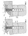
- FIG. 1is a cross sectional view of an arrangement of a soft-tissue fixation device in a first (as installed) position;
- FIG. 2is a cross sectional view of the soft-tissue fixation device of FIG. 1 in a second (compressed) position where the flange is positioned on an angle;
- FIG. 3is a side perspective view of another side of the soft-tissue fixation device of FIG. 1 ;
- FIG. 4is an exploded perspective view of the soft-tissue fixation device of FIG. 1 ;
- FIG. 5is a side exploded view of the soft-tissue fixation device of FIG. 1 ;
- FIG. 6is a bottom exploded perspective view of the soft-tissue fixation device of FIG. 1 ;
- FIG. 7is a cross-sectional view of the flange and proximal anchor of the soft-tissue fixation device of FIG. 1 ;
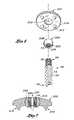
- FIG. 8illustrates an exemplary tool that can be used to implant the fixation device of FIG. 1 ;
- FIGS. 9A and 9Billustrate a variation of the tool and fixation device shown in FIG. 8 ;
- FIG. 10is a top perspective exploded view of an alternate embodiment of the fixation device.
- FIG. 11is a side exploded view of the fixation device shown in FIG. 10 .
- FIG. 1illustrates the fixation device 200 as installed (i.e., after placement attaching tissue to a bone).
- the fixation device 200can be compressed and/or the flange 202 rotated (i.e., angled) as shown in FIG. 2 .
- the flangeWhen the flange is compressed, it is retained in position such that the device does not move either distally or proximally.
- the length of the fixation device 200is variable depending on the amount of compression used. Preferably, the compression is performed via ratcheting rather than rotation to avoid rotation of the tissue.
- the fixation device 200includes an adjustable flange 202 that may be angled as shown in FIG. 2 .
- the flange 202“floats” such that it automatically rotates to the optimal angle for the bone to which the soft tissue is being attached.
- Such flexibilityi.e., ability to adjust the flange to various positions) allows for stronger tissue-to-bone fixation and low profile.
- the fixation device 200 of the present inventionmay be used to attach tissue or structure to the bone, such as in ligament reattachment and other soft tissue attachment procedures.
- the devicemay be used to repair a fracture 304 in which a soft tissue 300 is to be attached to the fractured bone 302 .
- U.S. Patent Application Ser. No. 10/623,193 entitled “Method and Apparatus for Spinal Fixation” filed on Jul. 18, 2003discloses a bone fixation device, various types of bone fractures and methods of repairing such fractures. The entire contents of this application are hereby expressly incorporated by reference.
- the device 200can be used for any type of injury (including, but not limited to fractures) in which it is desirable to attach soft tissue 300 (such as a tendon or a ligament) to a hard tissue 302 (such as a bone). Plates and washers, with or without tissue spikes for soft tissue attachment, and other implants may also be attached to bone, using either resorbable or nonresorbable fixation devices depending upon the implant and procedure.
- the fixation device 200may also be used to attach sutures to the bone, such as in any of a variety of tissue suspension procedures.
- peripheral applications for the fixation devicesinclude utilization of the device for fastening soft tissue such as capsule, tendon or ligament to bone.
- the device 200may also be used to attach a synthetic material such as marlex mesh, to bone or allograft material such as tensor fascia lata, to bone. In the process of doing so, retention of the material to bone may be accomplished with the collar, or the pin and or collar may be modified to accept a suture or other material for facilitation of this attachment.
- attachment of the posterior tibial tendon to the navicular bone in the Kidner operationmay be accomplished using an appropriately sized implant of the present invention along with a washer with distally extending soft tissue spikes.
- Navicular-cuneiform arthrodesismay be performed utilizing the device 200 and concurrent attachment of the tendon may be accomplished. Attachment of the tendon may be accomplished in the absence of arthrodesis by altering the placement of the implant in the adjacent bone.
- Ligament or capsule reattachment after rupture, avulsion or detachment, such as in the ankle, shoulder or kneecan also be accomplished using the devices disclosed herein.
- the cannulated design disclosedcan be fashioned to accept an antibiotic impregnated rod for the slow adsorption of medication locally. This may be beneficial for prophylaxis, especially in open wounds, or when osteomyelitis is present and stabilization of fracture fragments is indicated.
- a kitmay be assembled for field use by military or sport medical or paramedical personnel.
- This kitcontains an implanting tool, and a variety of implant device size and types.
- the kitmay include additional components such as sterilization or disinfectant materials, a skin stapler, bandages, gloves, and basic tools for emergent wound and fracture treatment.
- Antibiotic rodsmay be included for wound prophylaxis during transport.
- the soft tissue fixation device 200comprises a body 28 extending between a proximal end 30 and a distal end 32 .
- the proximal end 30 of the device 200is provided with a proximal anchor 204 .
- the proximal anchor 204defines a tubular body or housing 206 and is axially distally moveable along the body 28 .
- Complimentary locking structures 54 , 58 on the housing 206 and the body 28such as threads or ratchet-like structures resist proximal movement of the body 28 with respect to the anchor 204 under normal use conditions.
- the complimentary locking structures 54 , 58may permit the anchor 204 to be axially advanced along the body 28 by rotation.
- the complimentary locking structures 54 , 58are generally rounded but include some flat surfaces (e.g., two opposing flat surfaces) alternating with curved or rounded surfaces. In such a case one locking structure may include some flat surfaces while the complementary locking surface is uniformly circular. In other embodiments, the complimentary locking structures 54 , 58 may be uniformly circular. However, when attaching soft tissue to a bone, it is typically desirable to avoid such rotation as the rotation may cause the soft tissue 300 to be rotated. Preferably, the complimentary locking structures 54 , 58 permit the anchor 204 to be axially advanced along the body 28 without rotation of the soft tissue.
- the illustrated proximal anchor 204also includes a gap 205 , 305 (see FIGS. 4 , 6 , 7 and 10 ) such that the illustrated anchor 204 forms a locking spherical split ring collar.
- the proximal anchor 204can be formed without the gap 205 .
- the proximal anchor 204preferably includes a smooth and more preferably rounded outer surface portion 208 , which is configured to fit within a smooth and preferably rounded recessed portion 210 in the flange 202 .
- the recessed portion 210may actually be a hole.
- a member having a recessed portionmay be inserted in the hole.
- proximal end 30may include a recess. Proximal end 30 fits through hole 210 . In the embodiments shown in FIG. 10 , the recess in the proximal end 30 is engageable with gripping member 402 of an insertion tool 400 .
- the flange 202resists distal movement of the proximal anchor 204 while permitting at least limited rotation between the proximal anchor 204 and the flange 202 .
- the illustrated arrangementallows for angular movement of the flange 202 over the anchor 204 to accommodate variable anatomical angles of the bone surface.
- the flange 202includes a plurality of spikes 212 .
- the spikes 212provide additional gripping support especially when the flange 202 is positioned against soft tissue.
- the flange 202may be formed without the spikes 212 .
- the length, diameter and construction materials of the body 28can be varied, depending upon the intended clinical application. In embodiments optimized for various fractures or other injuries in an adult human population, the body 28 will generally be within the range of from about 10 mm to about 80 mm in length after sizing, and within the range of from about 2 mm to about 6 mm in maximum diameter.
- the major diameter of the helical anchormay be within the range of from about 3.5 mm to about 30 mm. In general, the appropriate dimensions of the body 28 will vary, depending upon the specific fracture or injury.
- the body 28comprises titanium. However, as will be described in more detail below, other metals or bioabsorbable or nonabsorbable polymeric materials may be utilized, depending upon the dimensions and desired structural integrity of the finished fixation device 200 .
- the distal end 32 of the body 28is provided with a cancellous bone anchor or distal cortical bone anchor 34 . Additional details of the distal bone anchor are described below.
- the present inventioncan be implanted with minimally invasive procedures.
- the fixation device 200can be implanted arthroscopically.
- a boremay be pre-drilled in the hard tissue 302 prior to insertion of the fixation device 200 .
- the fixation device 200is preferably self-tapping so that no pre-drilling is required.
- the proximal anchor 204is pre-loaded into the flange 202 .
- the bodyis then inserted into the member comprising the proximal anchor 204 and the flange 202 .
- the proximal anchor 304includes an extension member 310 .
- This extension memberallows for a greater range of compression.
- the body 28is inserted into the proximal anchor 204 /flange 202 such that the body 28 is recessed with respect to the proximal anchor 204 /flange 202 as shown in FIG. 1 .
- the fixation device 200is compressed (as shown in FIG.
- the body 28does not protrude through the flange 202 (i.e., the body 28 is flush or recessed with respect to the proximal surface 214 of the flange 202 .
- This configurationrequires a counterbore into the bone 302 slightly larger than the diameter and length d of the extension member 310 to allow the extension member 310 to seat into the bone 302 .
- the proximal end 30 of the body 28may be provided with a rotational coupling 422 , for allowing the body 28 to be rotationally coupled to a rotation device 420 .
- the proximal end 30 of the body 28may be desirably rotated to accomplish one or two discrete functions.
- the proximal end 30is rotated to remove the rotational coupling 422 following tensioning of the device.
- Rotation of the rotational coupling 422may also be utilized to rotationally drive the distal anchor into the bone.
- Any of a variety of rotation devicesmay be utilized, such as electric drills or hand tools (such as those shown in FIGS. 8 and 9A ), which allow the clinician to manually rotate the proximal end 30 of the body.
- the rotational coupling 422may have any of a variety of cross sectional configurations, such as one or more flats or splines.
- the rotational coupling 422comprises a proximal projection of the body 28 having an axial recess with a polygonal cross section, such as a hexagonal cross section.
- the rotational coupling 422may be a female component, machined or milled or attached to the proximal end 30 of the body 28 .
- the rotational couplingmay also be in the form of a male element, such as a hexagonal or other noncircular cross sectioned projection.
- the body 28is cannulated to accommodate installation over a placement (e.g., guide) wire as is understood in the art.
- the cross section of the illustrated central cannulationis circular but in other embodiments may be non circular, e.g., hexagonal, to accommodate a corresponding male tool for installation or removal of a removable portion 422 of the body 28 .
- the body 28may be partially or wholly solid.
- the distal anchor 34comprises a helical locking structure 72 for engaging cancellous and/or distal cortical bone.
- the locking structure 72comprises a flange that is wrapped around the axial lumen.
- the flangeextends through at least one and generally from about two to about 50 or more full revolutions depending upon the axial length of the distal anchor and intended application. In exemplary fixation devices, the flange will generally complete from about 2 to about 20 revolutions.
- the helical flange 72is preferably provided with a pitch and an axial spacing to optimize the retention force within cancellous bone, to optimize compression of the fracture.
- the helical flange 72 of the illustrated embodimenthas a generally triangular cross-sectional shape.
- the helical flange 72can have any of a variety of cross sectional shapes, such as rectangular, oval or other as deemed desirable for a particular application through routine experimentation in view of the disclosure herein.
- the outer edge of the helical flange 72defines an outer boundary.
- the ratio of the diameter of the outer boundary to the diameter of the central lumencan be optimized with respect to the desired retention force within the cancellous bone and giving due consideration to the structural integrity and strength of the distal anchor 34 .
- Another aspect of the distal anchor 34 that can be optimizedis the shape of the outer boundary and the central core, which in the illustrated embodiment are generally cylindrical.
- the various distal anchors described in U.S. Pat. No. 6,511,481, filed Mar. 30, 2001, and co-pending U.S. patent application Ser. No. 10/012,687, filed Nov. 13, 2001can be incorporated into the fixation device 12 described herein.
- the entire contents of these applicationsare hereby expressly incorporated by reference.
- the distal anchor 32may comprise a single helical thread surrounding a central core, much as in a conventional screw, which has been cannulated to facilitate placement over a wire.
- a double helical threadmay be utilized, with the distal end of the first thread rotationally offset from the distal end of the second thread.
- a double helical threadcan enable a greater axial travel for a given degree of rotation and greater retention force than a corresponding single helical thread.
- Specific distal anchor designscan be optimized for the intended use, taking into account desired performance characteristics, the integrity of the distal bone, and whether the distal anchor is intended to engage exclusively cancellous bone or will also engage cortical bone.
- the flange 202is preferably provided with a gripping structure to permit an insertion tool (such as the one shown in FIG. 8 or the one shown in FIGS. 9A and 9B ) to rotate the flange 202 .
- a gripping structuresuch as one or more slots, flats, bores or the like.
- the flange 202is provided with a circular recess 210 .
- the flange 202is provided with a polygonal recess, such as a pentagonal or hexagonal recess 210 .
- the recess 210may be in the flange or the flange may have a hole 210 and the proximal anchor which is inserted through the hole 210 may include a recess.
- the fixation devicemay be installed by pre-drilling.
- the clinicianfirst identifies a patient having an injury, such as a fracture, to be treated, which is fixable by an internal fixation device.
- an injurysuch as a fracture
- the clinicianaccesses the injury, reduces the fracture if necessary and selects a bone drill and drills a hole in accordance with conventional techniques.
- the diameter of the holemay be slightly larger than the diameter of the distal anchor 34 .
- the holepreferably extends up to or slightly beyond the fracture.
- the deviceis self-tapping.
- the pre-drilling process described aboveis optional.
- a fixation device 200 having an axial length and outside diameter suitable for the holeis selected.
- the distal end 32 of the fixation device 200is advanced distally into the hole until the distal anchor 34 reaches the distal end of the hole.
- the proximal anchor 204is carried by the fixation device 200 prior to advancing the body 28 into the hole. However, it may be attached following placement of the body 28 within the hole.
- the clinicianmay use a tool 400 , 420 such as the one shown in FIG. 8 or FIG. 9A to rotate the proximal anchor 204 and thus cancellous bone anchor 34 into the bone. Any of a variety of other driving devices, such as electric drills or hand tools may also be used.
- proximal tractionis applied to the proximal end 30 of body 28 .
- a tool 400 , 420such as the ones shown in FIGS. 8 and 9B is used.
- the tooluses a ratcheting motion so that the fixation device is compressed (such as is shown in FIG. 2 ) without rotating the soft tissue 302 .
- the proximal anchor 204is advanced distally until the anchor 204 fits snugly against the outer surface of the tissue adjacent the bone and the fracture is completely reduced.
- Appropriate tensioning of the fixation device 200could be accomplished by tactile feedback or through the use of a calibration device for applying a predetermined load on the implantation device.
- One advantage of the structure of the present inventionis the ability to adjust compression independently of the setting of the distal anchor 34 . Conventional hemostats, pliers or a calibrated loading device, could be used instead of or in combination with the tool 400 , 420 .
- fixation device 200With many fractures or other injuries, a single fixation device 200 may be all that is clinically indicated. However, two or three or more fixation devices 200 may be utilized to reduce a single fracture, depending upon the location and physical requirements of the injury.
- the proximal end of the fixation devices 200may be connected together such as through a three-holed plate or rod, or may be independent of each other.
- the access sitemay be closed and dressed in accordance with conventional wound closure techniques. Preferably, such closure and dressing will be performed after the device is installed ( FIG. 1 ), but prior to compression (shown in FIG. 2 ).
- the flange 202may include suture holes. In such embodiments, the device is inserted and compressed (as shown in FIG. 2 ). Sutures (through the suture holes) are inserted. Sutures can be inserted prior to or after insertion and compression.
- FIG. 8illustrates an exemplary tool 400 for installing a soft tissue fixation device 200 .
- the tool 400includes a gripping member 402 configured to mate with the recess 210 in the flange 202 .
- the fixation device 200is positioned over the tissue 300 .
- the tool 400is then used to rotate the tool until the fixation device 200 is installed in the bone 302 as shown in FIG. 1 .
- the tool 400can be used to ratchet the device so that the fixation device 200 is compressed and the flange is rotated, if desired, as shown in FIG. 2 .
- the body 28is recessed below the flange 202 .
- the proximal anchor 304includes an extension portion 310 to allow for a greater compression range. This final compression and/or flange rotation does not rotate the tissue 300 . This provides for a strong tissue fixation.
- the devicecannot be moved (unless the entire fixation device 200 is removed) once the device is inserted.
- FIGS. 9A and 9Billustrate an alternative fixation device 200 and installation tool 420 combination.
- the tool 420 shown in FIG. 9Adoes not include an integral gripping mechanism.
- a removable portion 422may form a part of the driving device 420 , which is used to rotate the proximal anchor 204 and thus cancellous bone anchor 34 into the bone.
- the removable portion 422has one end which is configured to removably engage to insertion tool 420 .
- insertion tool 420may include a recess sized and configured to engage with one end of the removable portion 422 of the insertion device 420 .
- the second, opposing, end of the removable portion 422 of the installation device 420is sized and configured to be removably engaged to the fixation device 200 .
- the flange 200 of the fixation device 200may include a recess 210 with which the end of the removable portion 422 of the insertion device 420 may be removably engaged.
- the removable portion 422is used to apply proximal traction so as to compress the fracture. After appropriate tensioning, the removable portion 422 can be de-coupled from the fixation device 200 and removed with the driving device 420 .
- the removable portion 422may be connected to a rotatable control such as a thumb wheel on the deployment device.
- a containermay be opened at the clinical site exposing the proximal end of the implant, such that the distal end of the removable portion 422 may be removably coupled thereto. Proximal retraction of the hand tool 420 will pull the implant out of its packaging.
- the implantmay then be positioned within the aperture in the bone, rotated to set the distal anchor, and the hand piece may be manipulated to place proximal traction on the removable portion 422 while simultaneously distally advancing the proximal anchor. Following appropriate tensioning across the fracture, the removable portion 422 may be disengaged from the implant, and removed from the patient.
- the removable portion 422may be disengaged from the implant by rotating a thumb wheel or other rotational control on the hand piece.
- the removable portion 422comprises a pull wire
- following appropriate tensioning across the fracturea first end of the pull wire is released such that the pull wire may be removed from the implant by proximal retraction of the second end which may be attached to the hand piece.
- the clinicianwill have access to an array of fixation devices 200 , having, for example, different diameters, axial lengths and, if applicable, angular relationships. These may be packaged one per package in sterile envelopes or peelable pouches, or in dispensing cartridges which may each hold a plurality of devices 200 . Upon encountering an injury for which the use of a fixation device is deemed appropriate, the clinician will assess the dimensions and load requirements, and select a fixation device 200 from the array, which meets the desired specifications.
- fixation devices of the present inventionmay be made from either conventional bioabsorbable materials or conventional non-absorbable materials, combinations thereof and equivalents thereof.
- natural materialssuch as allografts may be used.
- absorbable materialsinclude homopolymers and copolymers of lactide, glycolide, trimethylene carbonate, caprolactone, and p-dioxanone and blends thereof. The following two blends may be useful: (1) the blend of poly(p-dioxanone) and a lactide/glycolide copolymer, as disclosed in U.S. Pat. No.
- the fixation devicesmay also be made from conventional non-absorbable, biocompatible materials including stainless steel, titanium, alloys thereof, polymers, composites and the like and equivalents thereof.
- the distal anchorcomprises a metal helix
- the body and the proximal anchorcomprise a bioabsorbable material.
- the distal anchorcomprises a bioabsorbable material
- the body and proximal anchorcomprise either a bioabsorbable material or a non-absorbable material, connected by an absorbable link. This may be accomplished by providing a concentric fit between the distal anchor and the body, with a transverse absorbable pin extending therethrough. This embodiment will enable removal of the body following dissipation of the pin, while leaving the distal anchor within the bone.
- the components of the inventionmay contain one or more bioactive substances, such as antibiotics, chemotherapeutic substances, angiogenic growth factors, substances for accelerating the healing of the wound, growth hormones, antithrombogenic agents, bone growth accelerators or agents, and the like.
- bioactive substancessuch as antibiotics, chemotherapeutic substances, angiogenic growth factors, substances for accelerating the healing of the wound, growth hormones, antithrombogenic agents, bone growth accelerators or agents, and the like.
- bioactive implantsmay be desirable because they contribute to the healing of the injury in addition to providing mechanical support.
- the componentsmay be provided with any of a variety of structural modifications to accomplish various objectives, such as osteoincorporation, or more rapid or uniform absorption into the body.
- osteoincorporationmay be enhanced by providing a micropitted or otherwise textured surface on the components.
- capillary pathwaysmay be provided throughout the body and collar, such as by manufacturing the anchor and body from an open cell foam material, which produces tortuous pathways through the device. This construction increases the surface area of the device which is exposed to body fluids, thereby generally increasing the absorption rate.
- Capillary pathwaysmay alternatively be provided by laser drilling or other technique, which will be understood by those of skill in the art in view of the disclosure herein.
- the extent to which the anchor can be permeated by capillary pathways or open cell foam passagewaysmay be determined by balancing the desired structural integrity of the device with the desired reabsorption time, taking into account the particular strength and absorption characteristics of the desired polymer.
- U.S. Pat. No. 6,005,161is described in U.S. Pat. No. 6,005,161 as a poly(hydroxy) acid in the form of an interconnecting, open-cell meshwork which duplicates the architecture of human cancellous bone from the iliac crest and possesses physical property (strength) values in excess of those demonstrated by human (mammalian) iliac crest cancellous bone.
- the gross structureis said to maintain physical property values at least equal to those of human, iliac crest, cancellous bone for a minimum of 90 days following implantation.
- the disclosure of U.S. Pat. No. 6,005,161is incorporated by reference in its entirety herein.
- distal anchormay be configured to be used with a pre-drilled hole and/or self tapping.
- the components of the present inventionmay be sterilized by any of the well known sterilization techniques, depending on the type of material. Suitable sterilization techniques include heat sterilization, radiation sterilization, such as cobalt 60 irradiation or electron beams, ethylene oxide sterilization, and the like.
- any of the bone fixation devices of the present inventioncan be readily varied depending upon the intended application, as will be apparent to those of skill in the art in view of the disclosure herein.
- the present inventionhas been described in terms of certain preferred embodiments, other embodiments of the invention including variations in dimensions, configuration and materials will be apparent to those of skill in the art in view of the disclosure herein.
- all features discussed in connection with any one embodiment hereincan be readily adapted for use in other embodiments herein.
- the use of different terms or reference numerals for similar features in different embodimentsdoes not imply difference other than those which may be expressly set forth. Accordingly, the present invention is intended to be described solely by reference to the appended claims, and not limited to the preferred embodiments disclosed herein.
Landscapes
- Health & Medical Sciences (AREA)
- Life Sciences & Earth Sciences (AREA)
- Surgery (AREA)
- Veterinary Medicine (AREA)
- Rheumatology (AREA)
- Public Health (AREA)
- General Health & Medical Sciences (AREA)
- Engineering & Computer Science (AREA)
- Biomedical Technology (AREA)
- Heart & Thoracic Surgery (AREA)
- Animal Behavior & Ethology (AREA)
- Oral & Maxillofacial Surgery (AREA)
- Vascular Medicine (AREA)
- Transplantation (AREA)
- Cardiology (AREA)
- Rehabilitation Therapy (AREA)
- Nuclear Medicine, Radiotherapy & Molecular Imaging (AREA)
- Orthopedic Medicine & Surgery (AREA)
- Medical Informatics (AREA)
- Molecular Biology (AREA)
- Surgical Instruments (AREA)
- Prostheses (AREA)
Abstract
Description
Claims (17)
Priority Applications (6)
| Application Number | Priority Date | Filing Date | Title |
|---|---|---|---|
| US10/719,086US7175625B2 (en) | 2002-11-25 | 2003-11-21 | Soft tissue anchor and method of using same |
| EP03783763AEP1569569A4 (en) | 2002-11-25 | 2003-11-24 | Soft tissue anchor and method of using same |
| JP2004555688AJP2006507098A (en) | 2002-11-25 | 2003-11-24 | Soft tissue fixation device and method of use thereof |
| PCT/US2003/037562WO2004047617A2 (en) | 2002-11-25 | 2003-11-24 | Soft tissue anchor and method of using same |
| AU2003291168AAU2003291168A1 (en) | 2002-11-25 | 2003-11-24 | Soft tissue anchor and method of using same |
| US11/623,282US20070179505A1 (en) | 2002-11-25 | 2007-01-15 | Soft tissue anchor and method of using same |
Applications Claiming Priority (2)
| Application Number | Priority Date | Filing Date | Title |
|---|---|---|---|
| US42884702P | 2002-11-25 | 2002-11-25 | |
| US10/719,086US7175625B2 (en) | 2002-11-25 | 2003-11-21 | Soft tissue anchor and method of using same |
Related Child Applications (1)
| Application Number | Title | Priority Date | Filing Date |
|---|---|---|---|
| US11/623,282ContinuationUS20070179505A1 (en) | 2002-11-25 | 2007-01-15 | Soft tissue anchor and method of using same |
Publications (2)
| Publication Number | Publication Date |
|---|---|
| US20040106925A1 US20040106925A1 (en) | 2004-06-03 |
| US7175625B2true US7175625B2 (en) | 2007-02-13 |
Family
ID=32397156
Family Applications (2)
| Application Number | Title | Priority Date | Filing Date |
|---|---|---|---|
| US10/719,086Expired - LifetimeUS7175625B2 (en) | 2002-11-25 | 2003-11-21 | Soft tissue anchor and method of using same |
| US11/623,282AbandonedUS20070179505A1 (en) | 2002-11-25 | 2007-01-15 | Soft tissue anchor and method of using same |
Family Applications After (1)
| Application Number | Title | Priority Date | Filing Date |
|---|---|---|---|
| US11/623,282AbandonedUS20070179505A1 (en) | 2002-11-25 | 2007-01-15 | Soft tissue anchor and method of using same |
Country Status (5)
| Country | Link |
|---|---|
| US (2) | US7175625B2 (en) |
| EP (1) | EP1569569A4 (en) |
| JP (1) | JP2006507098A (en) |
| AU (1) | AU2003291168A1 (en) |
| WO (1) | WO2004047617A2 (en) |
Cited By (71)
| Publication number | Priority date | Publication date | Assignee | Title |
|---|---|---|---|---|
| US20050228387A1 (en)* | 2004-04-08 | 2005-10-13 | Paul David C | Load distribution crown |
| US20060264951A1 (en)* | 2005-05-18 | 2006-11-23 | Nelson Charles L | Minimally Invasive Actuable Bone Fixation Devices Having a Retractable Interdigitation Process |
| US20070156153A1 (en)* | 2005-12-29 | 2007-07-05 | Industrial Technology Research Institute | Device and method for fixing soft tissue |
| US20080132896A1 (en)* | 2006-11-22 | 2008-06-05 | Sonoma Orthopedic Products, Inc. | Curved orthopedic tool |
| US20080140078A1 (en)* | 2006-11-22 | 2008-06-12 | Sonoma Orthopedic Products, Inc. | Surgical tools for use in deploying bone repair devices |
| US20080149115A1 (en)* | 2006-11-22 | 2008-06-26 | Sonoma Orthopedic Products, Inc. | Surgical station for orthopedic reconstruction surgery |
| US20080161805A1 (en)* | 2006-11-22 | 2008-07-03 | Sonoma Orthopedic Products, Inc. | Fracture fixation device, tools and methods |
| US20090234386A1 (en)* | 2008-03-11 | 2009-09-17 | Dean John C | Suture Cleat for Soft Tissue Injury Repair |
| US20090254120A1 (en)* | 2008-01-09 | 2009-10-08 | Argenta Louis C | Device and method for treating central nervous system pathology |
| US20100087859A1 (en)* | 2008-10-03 | 2010-04-08 | Jackson Jr Darrell | Facet button assembly and related surgical methods |
| US20100094347A1 (en)* | 2005-05-18 | 2010-04-15 | Nelson Charles L | Fracture fixation device, tools and methods |
| US7766911B1 (en) | 2002-07-05 | 2010-08-03 | Theken Spine, Llc | Fixed and variable locking fixation assembly |
| US7931651B2 (en) | 2006-11-17 | 2011-04-26 | Wake Lake University Health Sciences | External fixation assembly and method of use |
| US20110184510A1 (en)* | 2010-01-22 | 2011-07-28 | 4Tech, Sarl | Tricuspid valve repair using tension |
| US20110218585A1 (en)* | 2010-03-08 | 2011-09-08 | Krinke Todd A | Apparatus and methods for bone repair |
| US8287538B2 (en) | 2008-01-14 | 2012-10-16 | Conventus Orthopaedics, Inc. | Apparatus and methods for fracture repair |
| US8377016B2 (en) | 2007-01-10 | 2013-02-19 | Wake Forest University Health Sciences | Apparatus and method for wound treatment employing periodic sub-atmospheric pressure |
| US8409257B2 (en) | 2010-11-10 | 2013-04-02 | Warsaw Othopedic, Inc. | Systems and methods for facet joint stabilization |
| US8834520B2 (en) | 2007-10-10 | 2014-09-16 | Wake Forest University | Devices and methods for treating spinal cord tissue |
| US8906022B2 (en) | 2010-03-08 | 2014-12-09 | Conventus Orthopaedics, Inc. | Apparatus and methods for securing a bone implant |
| US8915499B2 (en) | 2010-11-09 | 2014-12-23 | Black & Decker Inc. | Universal accessories for oscillating power tools |
| US8925931B2 (en) | 2010-04-29 | 2015-01-06 | Black & Decker Inc. | Oscillating tool |
| US8961596B2 (en) | 2010-01-22 | 2015-02-24 | 4Tech Inc. | Method and apparatus for tricuspid valve repair using tension |
| US8961516B2 (en) | 2005-05-18 | 2015-02-24 | Sonoma Orthopedic Products, Inc. | Straight intramedullary fracture fixation devices and methods |
| US8961518B2 (en) | 2010-01-20 | 2015-02-24 | Conventus Orthopaedics, Inc. | Apparatus and methods for bone access and cavity preparation |
| US8961594B2 (en) | 2012-05-31 | 2015-02-24 | 4Tech Inc. | Heart valve repair system |
| US9060820B2 (en) | 2005-05-18 | 2015-06-23 | Sonoma Orthopedic Products, Inc. | Segmented intramedullary fracture fixation devices and methods |
| US9149923B2 (en) | 2010-11-09 | 2015-10-06 | Black & Decker Inc. | Oscillating tools and accessories |
| US9155574B2 (en) | 2006-05-17 | 2015-10-13 | Sonoma Orthopedic Products, Inc. | Bone fixation device, tools and methods |
| US9186770B2 (en) | 2010-04-29 | 2015-11-17 | Black & Decker Inc. | Oscillating tool attachment feature |
| US9241702B2 (en) | 2010-01-22 | 2016-01-26 | 4Tech Inc. | Method and apparatus for tricuspid valve repair using tension |
| US9289193B2 (en) | 2008-07-18 | 2016-03-22 | Wake Forest University Health Sciences | Apparatus and method for cardiac tissue modulation by topical application of vacuum to minimize cell death and damage |
| US9307980B2 (en) | 2010-01-22 | 2016-04-12 | 4Tech Inc. | Tricuspid valve repair using tension |
| US9474560B2 (en) | 2004-04-08 | 2016-10-25 | Globus Medical, Inc | Load distribution crown |
| US9693865B2 (en) | 2013-01-09 | 2017-07-04 | 4 Tech Inc. | Soft tissue depth-finding tool |
| US9730739B2 (en) | 2010-01-15 | 2017-08-15 | Conventus Orthopaedics, Inc. | Rotary-rigid orthopaedic rod |
| US9770278B2 (en) | 2014-01-17 | 2017-09-26 | Arthrex, Inc. | Dual tip guide wire |
| US9801720B2 (en) | 2014-06-19 | 2017-10-31 | 4Tech Inc. | Cardiac tissue cinching |
| US9814499B2 (en) | 2014-09-30 | 2017-11-14 | Arthrex, Inc. | Intramedullary fracture fixation devices and methods |
| US20180008317A1 (en)* | 2010-11-30 | 2018-01-11 | Genossis Llc | Bone Compression and Fixation Devices |
| US9907547B2 (en) | 2014-12-02 | 2018-03-06 | 4Tech Inc. | Off-center tissue anchors |
| US9907681B2 (en) | 2013-03-14 | 2018-03-06 | 4Tech Inc. | Stent with tether interface |
| USD814900S1 (en) | 2017-01-16 | 2018-04-10 | Black & Decker Inc. | Blade for oscillating power tools |
| US10022132B2 (en) | 2013-12-12 | 2018-07-17 | Conventus Orthopaedics, Inc. | Tissue displacement tools and methods |
| US10022114B2 (en) | 2013-10-30 | 2018-07-17 | 4Tech Inc. | Percutaneous tether locking |
| US10039643B2 (en) | 2013-10-30 | 2018-08-07 | 4Tech Inc. | Multiple anchoring-point tension system |
| US10052095B2 (en) | 2013-10-30 | 2018-08-21 | 4Tech Inc. | Multiple anchoring-point tension system |
| US10058323B2 (en) | 2010-01-22 | 2018-08-28 | 4 Tech Inc. | Tricuspid valve repair using tension |
| USD832666S1 (en) | 2012-07-16 | 2018-11-06 | Black & Decker Inc. | Oscillating saw blade |
| US10265778B2 (en) | 2017-01-16 | 2019-04-23 | Black & Decker Inc. | Accessories for oscillating power tools |
| US10413422B2 (en) | 2013-03-07 | 2019-09-17 | DePuy Synthes Products, Inc. | Intervertebral implant |
| US10806579B2 (en) | 2017-10-20 | 2020-10-20 | Boston Scientific Scimed, Inc. | Heart valve repair implant for treating tricuspid regurgitation |
| US10918426B2 (en) | 2017-07-04 | 2021-02-16 | Conventus Orthopaedics, Inc. | Apparatus and methods for treatment of a bone |
| US11426286B2 (en) | 2020-03-06 | 2022-08-30 | Eit Emerging Implant Technologies Gmbh | Expandable intervertebral implant |
| US11452554B2 (en)* | 2014-07-16 | 2022-09-27 | The Regents Of The University Of Colorado | System and method for fastening of two or more interacting elements |
| US11452607B2 (en) | 2010-10-11 | 2022-09-27 | DePuy Synthes Products, Inc. | Expandable interspinous process spacer implant |
| US11510788B2 (en) | 2016-06-28 | 2022-11-29 | Eit Emerging Implant Technologies Gmbh | Expandable, angularly adjustable intervertebral cages |
| US11596419B2 (en) | 2017-03-09 | 2023-03-07 | Flower Orthopedics Corporation | Plating depth gauge and countersink instrument |
| US11622868B2 (en) | 2007-06-26 | 2023-04-11 | DePuy Synthes Products, Inc. | Highly lordosed fusion cage |
| US11660206B2 (en) | 2006-12-07 | 2023-05-30 | DePuy Synthes Products, Inc. | Intervertebral implant |
| US11752009B2 (en) | 2021-04-06 | 2023-09-12 | Medos International Sarl | Expandable intervertebral fusion cage |
| US11850160B2 (en) | 2021-03-26 | 2023-12-26 | Medos International Sarl | Expandable lordotic intervertebral fusion cage |
| US11857417B2 (en) | 2020-08-16 | 2024-01-02 | Trilio Medical Ltd. | Leaflet support |
| US11872139B2 (en) | 2010-06-24 | 2024-01-16 | DePuy Synthes Products, Inc. | Enhanced cage insertion assembly |
| US11911287B2 (en) | 2010-06-24 | 2024-02-27 | DePuy Synthes Products, Inc. | Lateral spondylolisthesis reduction cage |
| US12011361B2 (en) | 2008-04-05 | 2024-06-18 | DePuy Synthes Products, Inc. | Expandable intervertebral implant |
| US12090064B2 (en) | 2022-03-01 | 2024-09-17 | Medos International Sarl | Stabilization members for expandable intervertebral implants, and related systems and methods |
| US12097124B2 (en) | 2009-03-30 | 2024-09-24 | DePuy Synthes Products, Inc. | Zero profile spinal fusion cage |
| US12427031B2 (en) | 2017-05-08 | 2025-09-30 | Medos International Sarl | Expandable cage |
| US12433757B2 (en) | 2016-06-28 | 2025-10-07 | Eit Emerging Implant Technologies Gmbh | Expandable, angularly adjustable and articulating intervertebral cages |
| US12440346B2 (en) | 2023-03-31 | 2025-10-14 | DePuy Synthes Products, Inc. | Expandable intervertebral implant |
Families Citing this family (144)
| Publication number | Priority date | Publication date | Assignee | Title |
|---|---|---|---|---|
| US8070786B2 (en)* | 1993-01-21 | 2011-12-06 | Acumed Llc | System for fusing joints |
| US9161793B2 (en) | 1993-01-21 | 2015-10-20 | Acumed Llc | Axial tension screw |
| US7833250B2 (en) | 2004-11-10 | 2010-11-16 | Jackson Roger P | Polyaxial bone screw with helically wound capture connection |
| US7862587B2 (en) | 2004-02-27 | 2011-01-04 | Jackson Roger P | Dynamic stabilization assemblies, tool set and method |
| US6793678B2 (en) | 2002-06-27 | 2004-09-21 | Depuy Acromed, Inc. | Prosthetic intervertebral motion disc having dampening |
| US8876868B2 (en) | 2002-09-06 | 2014-11-04 | Roger P. Jackson | Helical guide and advancement flange with radially loaded lip |
| US8002812B2 (en) | 2002-10-10 | 2011-08-23 | Us Spine, Inc. | Bone fixation implant system and method |
| US7621918B2 (en) | 2004-11-23 | 2009-11-24 | Jackson Roger P | Spinal fixation tool set and method |
| US7377923B2 (en) | 2003-05-22 | 2008-05-27 | Alphatec Spine, Inc. | Variable angle spinal screw assembly |
| US7766915B2 (en) | 2004-02-27 | 2010-08-03 | Jackson Roger P | Dynamic fixation assemblies with inner core and outer coil-like member |
| US8366753B2 (en) | 2003-06-18 | 2013-02-05 | Jackson Roger P | Polyaxial bone screw assembly with fixed retaining structure |
| US8926670B2 (en) | 2003-06-18 | 2015-01-06 | Roger P. Jackson | Polyaxial bone screw assembly |
| US7776067B2 (en) | 2005-05-27 | 2010-08-17 | Jackson Roger P | Polyaxial bone screw with shank articulation pressure insert and method |
| US7967850B2 (en) | 2003-06-18 | 2011-06-28 | Jackson Roger P | Polyaxial bone anchor with helical capture connection, insert and dual locking assembly |
| US7527638B2 (en) | 2003-12-16 | 2009-05-05 | Depuy Spine, Inc. | Methods and devices for minimally invasive spinal fixation element placement |
| US7179261B2 (en) | 2003-12-16 | 2007-02-20 | Depuy Spine, Inc. | Percutaneous access devices and bone anchor assemblies |
| US11419642B2 (en) | 2003-12-16 | 2022-08-23 | Medos International Sarl | Percutaneous access devices and bone anchor assemblies |
| US11241261B2 (en) | 2005-09-30 | 2022-02-08 | Roger P Jackson | Apparatus and method for soft spinal stabilization using a tensionable cord and releasable end structure |
| JP2007525274A (en) | 2004-02-27 | 2007-09-06 | ロジャー・ピー・ジャクソン | Orthopedic implant rod reduction instrument set and method |
| US8152810B2 (en) | 2004-11-23 | 2012-04-10 | Jackson Roger P | Spinal fixation tool set and method |
| US7160300B2 (en) | 2004-02-27 | 2007-01-09 | Jackson Roger P | Orthopedic implant rod reduction tool set and method |
| US8257394B2 (en) | 2004-05-07 | 2012-09-04 | Usgi Medical, Inc. | Apparatus and methods for positioning and securing anchors |
| US8114127B2 (en) | 2004-06-22 | 2012-02-14 | Hs West Investments, Llc | Bone anchors for use in attaching soft tissue to bone |
| US9387313B2 (en) | 2004-08-03 | 2016-07-12 | Interventional Spine, Inc. | Telescopic percutaneous tissue dilation systems and related methods |
| WO2006017507A2 (en) | 2004-08-03 | 2006-02-16 | Triage Medical | Telescopic percutaneous tissue dilation systems and related methods |
| US8414648B2 (en)* | 2004-08-09 | 2013-04-09 | Si-Bone Inc. | Apparatus, systems, and methods for achieving trans-iliac lumbar fusion |
| US8425570B2 (en) | 2004-08-09 | 2013-04-23 | Si-Bone Inc. | Apparatus, systems, and methods for achieving anterior lumbar interbody fusion |
| US20180228621A1 (en) | 2004-08-09 | 2018-08-16 | Mark A. Reiley | Apparatus, systems, and methods for the fixation or fusion of bone |
| US9662158B2 (en) | 2004-08-09 | 2017-05-30 | Si-Bone Inc. | Systems and methods for the fixation or fusion of bone at or near a sacroiliac joint |
| US8444693B2 (en)* | 2004-08-09 | 2013-05-21 | Si-Bone Inc. | Apparatus, systems, and methods for achieving lumbar facet fusion |
| US8388667B2 (en) | 2004-08-09 | 2013-03-05 | Si-Bone, Inc. | Systems and methods for the fixation or fusion of bone using compressive implants |
| US8470004B2 (en) | 2004-08-09 | 2013-06-25 | Si-Bone Inc. | Apparatus, systems, and methods for stabilizing a spondylolisthesis |
| US9949843B2 (en) | 2004-08-09 | 2018-04-24 | Si-Bone Inc. | Apparatus, systems, and methods for the fixation or fusion of bone |
| US20070156241A1 (en) | 2004-08-09 | 2007-07-05 | Reiley Mark A | Systems and methods for the fixation or fusion of bone |
| US20060036251A1 (en) | 2004-08-09 | 2006-02-16 | Reiley Mark A | Systems and methods for the fixation or fusion of bone |
| US7651502B2 (en) | 2004-09-24 | 2010-01-26 | Jackson Roger P | Spinal fixation tool set and method for rod reduction and fastener insertion |
| US8025680B2 (en) | 2004-10-20 | 2011-09-27 | Exactech, Inc. | Systems and methods for posterior dynamic stabilization of the spine |
| US8267969B2 (en) | 2004-10-20 | 2012-09-18 | Exactech, Inc. | Screw systems and methods for use in stabilization of bone structures |
| US8162985B2 (en) | 2004-10-20 | 2012-04-24 | The Board Of Trustees Of The Leland Stanford Junior University | Systems and methods for posterior dynamic stabilization of the spine |
| MX2007005081A (en)* | 2004-10-26 | 2007-10-03 | U S Spinal Technologies Llc | Bone fixation implant system and method. |
| US8926672B2 (en) | 2004-11-10 | 2015-01-06 | Roger P. Jackson | Splay control closure for open bone anchor |
| US7572279B2 (en)* | 2004-11-10 | 2009-08-11 | Jackson Roger P | Polyaxial bone screw with discontinuous helically wound capture connection |
| WO2006057837A1 (en) | 2004-11-23 | 2006-06-01 | Jackson Roger P | Spinal fixation tool attachment structure |
| US9168069B2 (en) | 2009-06-15 | 2015-10-27 | Roger P. Jackson | Polyaxial bone anchor with pop-on shank and winged insert with lower skirt for engaging a friction fit retainer |
| US8444681B2 (en) | 2009-06-15 | 2013-05-21 | Roger P. Jackson | Polyaxial bone anchor with pop-on shank, friction fit retainer and winged insert |
| US8523865B2 (en) | 2005-07-22 | 2013-09-03 | Exactech, Inc. | Tissue splitter |
| WO2007059199A2 (en) | 2005-11-14 | 2007-05-24 | C.R. Bard, Inc. | Sling anchor system |
| US7731738B2 (en)* | 2005-12-09 | 2010-06-08 | Orthopro, Llc | Cannulated screw |
| JP4885979B2 (en)* | 2005-12-22 | 2012-02-29 | エス.ウェスト ジュニア ヒュー | Bone anchor used to attach soft tissue to bone |
| ITBO20060008U1 (en)* | 2006-01-27 | 2007-07-28 | Citieffe Srl | ANCHORAGE FOR TENDONS USED IN THE REBUILDING OF BINDING, IN PARTICULAR OF THE CRUCED KNEE BOND. |
| US8118849B2 (en)* | 2006-03-17 | 2012-02-21 | Tornier, Inc. | Bone screw with selectively securable washer |
| US20080015576A1 (en)* | 2006-04-28 | 2008-01-17 | Whipple Dale E | Large diameter bone anchor assembly |
| US8361129B2 (en) | 2006-04-28 | 2013-01-29 | Depuy Spine, Inc. | Large diameter bone anchor assembly |
| US8133262B2 (en)* | 2006-04-28 | 2012-03-13 | Depuy Spine, Inc. | Large diameter bone anchor assembly |
| US8870916B2 (en) | 2006-07-07 | 2014-10-28 | USGI Medical, Inc | Low profile tissue anchors, tissue anchor systems, and methods for their delivery and use |
| WO2008033950A2 (en) | 2006-09-13 | 2008-03-20 | C. R. Bard, Inc. | Urethral support system |
| US7857840B2 (en)* | 2006-10-02 | 2010-12-28 | The Cleveland Clinic Foundation | Fastener assembly |
| US8361130B2 (en) | 2006-10-06 | 2013-01-29 | Depuy Spine, Inc. | Bone screw fixation |
| US8096996B2 (en) | 2007-03-20 | 2012-01-17 | Exactech, Inc. | Rod reducer |
| ES2373770T3 (en)* | 2006-11-22 | 2012-02-08 | Biedermann Motech Gmbh | BONE ANCHORAGE DEVICE. |
| CA2670988C (en) | 2006-12-08 | 2014-03-25 | Roger P. Jackson | Tool system for dynamic spinal implants |
| US8702762B2 (en) | 2007-03-27 | 2014-04-22 | Depuy Spine, Inc. | Passive screw locking mechanism |
| WO2008120202A2 (en)* | 2007-03-29 | 2008-10-09 | Technion Research & Development Foundation Ltd. | Antibodies, methods and kits for diagnosing and treating melanoma |
| WO2008120203A2 (en)* | 2007-03-29 | 2008-10-09 | Technion Research & Development Foundation Ltd. | Antibodies and their uses for diagnosis and treatment of cytomegalovirus infection and associated diseases |
| US8979904B2 (en) | 2007-05-01 | 2015-03-17 | Roger P Jackson | Connecting member with tensioned cord, low profile rigid sleeve and spacer with torsion control |
| US8206280B2 (en) | 2007-11-13 | 2012-06-26 | C. R. Bard, Inc. | Adjustable tissue support member |
| FR2925287B1 (en)* | 2007-12-21 | 2010-12-17 | B & G | DEVICE FOR ANCHORING A FABRIC INTO A BONE |
| EP2249717B1 (en)* | 2008-01-14 | 2015-02-25 | K2M, Inc. | Spinal fixation device |
| EP2237748B1 (en) | 2008-01-17 | 2012-09-05 | Synthes GmbH | An expandable intervertebral implant |
| US8282675B2 (en)* | 2008-01-25 | 2012-10-09 | Depuy Spine, Inc. | Anti-backout mechanism |
| US8092505B2 (en)* | 2008-01-28 | 2012-01-10 | Acumed Llc | Bone nail |
| US20090275993A1 (en)* | 2008-04-30 | 2009-11-05 | Phan Christopher U | Apparatus and methods for inserting facet screws |
| AU2010260521C1 (en) | 2008-08-01 | 2013-08-01 | Roger P. Jackson | Longitudinal connecting member with sleeved tensioned cords |
| WO2010121234A1 (en)* | 2009-04-17 | 2010-10-21 | Hodge W Andrew | Internal joint bracing system and suture anchoring assembly therefore |
| US8961576B2 (en) | 2010-04-18 | 2015-02-24 | Advanced Bone Anchor, Llc | Internal joint bracing system and suture anchoring assembly therefore |
| US8998959B2 (en) | 2009-06-15 | 2015-04-07 | Roger P Jackson | Polyaxial bone anchors with pop-on shank, fully constrained friction fit retainer and lock and release insert |
| US11229457B2 (en) | 2009-06-15 | 2022-01-25 | Roger P. Jackson | Pivotal bone anchor assembly with insert tool deployment |
| CN103826560A (en) | 2009-06-15 | 2014-05-28 | 罗杰.P.杰克逊 | Polyaxial Bone Anchor with Socket Stem and Winged Inserts with Friction Fit Compression Collars |
| US8361123B2 (en) | 2009-10-16 | 2013-01-29 | Depuy Spine, Inc. | Bone anchor assemblies and methods of manufacturing and use thereof |
| US8864768B2 (en) | 2009-11-20 | 2014-10-21 | Zimmer Knee Creations, Inc. | Coordinate mapping system for joint treatment |
| US8821504B2 (en) | 2009-11-20 | 2014-09-02 | Zimmer Knee Creations, Inc. | Method for treating joint pain and associated instruments |
| US8951261B2 (en) | 2009-11-20 | 2015-02-10 | Zimmer Knee Creations, Inc. | Subchondral treatment of joint pain |
| WO2011063240A1 (en)* | 2009-11-20 | 2011-05-26 | Knee Creations, Llc | Implantable devices for subchondral treatment of joint pain |
| JP2013511356A (en) | 2009-11-20 | 2013-04-04 | ニー・クリエイションズ・リミテッド・ライアビリティ・カンパニー | Device for variable angle approach to joints |
| EP2501303B1 (en) | 2009-11-20 | 2020-02-12 | Zimmer Knee Creations, Inc. | Navigation and positioning instruments for joint repair |
| US9259257B2 (en) | 2009-11-20 | 2016-02-16 | Zimmer Knee Creations, Inc. | Instruments for targeting a joint defect |
| WO2011063260A1 (en) | 2009-11-20 | 2011-05-26 | Knee Creations, Llc | Bone-derived implantable devices for subchondral treatment of joint pain |
| US9393129B2 (en) | 2009-12-10 | 2016-07-19 | DePuy Synthes Products, Inc. | Bellows-like expandable interbody fusion cage |
| US8142477B2 (en) | 2010-01-21 | 2012-03-27 | Warsaw Orthopedic, Inc. | Retaining system |
| US20110313465A1 (en)* | 2010-06-16 | 2011-12-22 | Interventional Spine, Inc. | Method and apparatus for spinal stabilization |
| US8623091B2 (en) | 2010-06-29 | 2014-01-07 | DePuy Synthes Products, LLC | Distractible intervertebral implant |
| CA2849887A1 (en)* | 2011-09-26 | 2013-04-04 | Artack Medical (2013) Ltd. | Surgical fastening device and method |
| US8911479B2 (en) | 2012-01-10 | 2014-12-16 | Roger P. Jackson | Multi-start closures for open implants |
| US8584853B2 (en)* | 2012-02-16 | 2013-11-19 | Biomedical Enterprises, Inc. | Method and apparatus for an orthopedic fixation system |
| US8778026B2 (en) | 2012-03-09 | 2014-07-15 | Si-Bone Inc. | Artificial SI joint |
| US10363140B2 (en) | 2012-03-09 | 2019-07-30 | Si-Bone Inc. | Systems, device, and methods for joint fusion |
| US9044321B2 (en) | 2012-03-09 | 2015-06-02 | Si-Bone Inc. | Integrated implant |
| EP3818947B1 (en) | 2012-05-04 | 2023-08-30 | SI-Bone, Inc. | Fenestrated implant |
| EP2877127B1 (en) | 2012-07-26 | 2019-08-21 | Synthes GmbH | Expandable implant |
| US20150272567A1 (en) | 2012-08-03 | 2015-10-01 | Stabilynx, Inc. | Devices, systems, and methods for attaching soft tissue to bone tissue |
| US9861353B2 (en) | 2012-08-03 | 2018-01-09 | Stabilynx, Inc. | Devices, systems, and methods for attaching soft tissue to bone tissue |
| US8945139B2 (en) | 2012-08-20 | 2015-02-03 | Stryker Trauma Gmbh | Bone screw and washer insertion tool |
| US20140067069A1 (en) | 2012-08-30 | 2014-03-06 | Interventional Spine, Inc. | Artificial disc |
| US9133978B2 (en)* | 2012-10-12 | 2015-09-15 | Jeffrey Scott Roddenberry | Mountable attachment apparatus and method |
| US8911478B2 (en) | 2012-11-21 | 2014-12-16 | Roger P. Jackson | Splay control closure for open bone anchor |
| US10058354B2 (en) | 2013-01-28 | 2018-08-28 | Roger P. Jackson | Pivotal bone anchor assembly with frictional shank head seating surfaces |
| US8852239B2 (en) | 2013-02-15 | 2014-10-07 | Roger P Jackson | Sagittal angle screw with integral shank and receiver |
| US9717601B2 (en) | 2013-02-28 | 2017-08-01 | DePuy Synthes Products, Inc. | Expandable intervertebral implant, system, kit and method |
| US10456182B2 (en) | 2013-03-13 | 2019-10-29 | Paragon 28, Inc. | Force distribution implant, assembly and kit |
| WO2014145902A1 (en) | 2013-03-15 | 2014-09-18 | Si-Bone Inc. | Implants for spinal fixation or fusion |
| US9155531B2 (en)* | 2013-03-15 | 2015-10-13 | Smith & Nephew, Inc. | Miniaturized dual drive open architecture suture anchor |
| US9526488B2 (en)* | 2013-03-15 | 2016-12-27 | Smith & Nephew, Inc. | Fenestrated locking suture anchor assembly |
| US11147688B2 (en) | 2013-10-15 | 2021-10-19 | Si-Bone Inc. | Implant placement |
| US9839448B2 (en) | 2013-10-15 | 2017-12-12 | Si-Bone Inc. | Implant placement |
| US9566092B2 (en) | 2013-10-29 | 2017-02-14 | Roger P. Jackson | Cervical bone anchor with collet retainer and outer locking sleeve |
| US9717533B2 (en) | 2013-12-12 | 2017-08-01 | Roger P. Jackson | Bone anchor closure pivot-splay control flange form guide and advancement structure |
| US9451993B2 (en) | 2014-01-09 | 2016-09-27 | Roger P. Jackson | Bi-radial pop-on cervical bone anchor |
| US10213231B2 (en)* | 2014-01-28 | 2019-02-26 | Life Spine, Inc. | System and method for reducing and stabilizing a bone fracture |
| US10064658B2 (en) | 2014-06-04 | 2018-09-04 | Roger P. Jackson | Polyaxial bone anchor with insert guides |
| US9597119B2 (en) | 2014-06-04 | 2017-03-21 | Roger P. Jackson | Polyaxial bone anchor with polymer sleeve |
| JP6542362B2 (en) | 2014-09-18 | 2019-07-10 | エスアイ−ボーン・インコーポレイテッドSi−Bone, Inc. | Matrix implant |
| US10166033B2 (en) | 2014-09-18 | 2019-01-01 | Si-Bone Inc. | Implants for bone fixation or fusion |
| US11426290B2 (en) | 2015-03-06 | 2022-08-30 | DePuy Synthes Products, Inc. | Expandable intervertebral implant, system, kit and method |
| US10376206B2 (en) | 2015-04-01 | 2019-08-13 | Si-Bone Inc. | Neuromonitoring systems and methods for bone fixation or fusion procedures |
| US9913727B2 (en) | 2015-07-02 | 2018-03-13 | Medos International Sarl | Expandable implant |
| US9895169B2 (en)* | 2015-08-21 | 2018-02-20 | Globus Medical, Inc. | Self in-fusing pedicle screw implant |
| US10537436B2 (en) | 2016-11-01 | 2020-01-21 | DePuy Synthes Products, Inc. | Curved expandable cage |
| US10888433B2 (en) | 2016-12-14 | 2021-01-12 | DePuy Synthes Products, Inc. | Intervertebral implant inserter and related methods |
| US11344424B2 (en) | 2017-06-14 | 2022-05-31 | Medos International Sarl | Expandable intervertebral implant and related methods |
| US11376050B2 (en) | 2017-06-27 | 2022-07-05 | Medos International Sarl | Bone screw |
| US10940016B2 (en) | 2017-07-05 | 2021-03-09 | Medos International Sarl | Expandable intervertebral fusion cage |
| US11116519B2 (en) | 2017-09-26 | 2021-09-14 | Si-Bone Inc. | Systems and methods for decorticating the sacroiliac joint |
| US10772667B2 (en)* | 2017-12-22 | 2020-09-15 | Medos International Sarl | Bone screw with cutting tip |
| ES3011907T3 (en) | 2018-03-28 | 2025-04-08 | Si Bone Inc | Threaded implants for use across bone segments |
| US11045238B2 (en)* | 2018-06-20 | 2021-06-29 | Life Spine, Inc. | Bone screw implant for sacroiliac joint fusion |
| US11446156B2 (en) | 2018-10-25 | 2022-09-20 | Medos International Sarl | Expandable intervertebral implant, inserter instrument, and related methods |
| EP4613244A2 (en) | 2019-02-14 | 2025-09-10 | SI-Bone Inc. | Implants for spinal fixation and or fusion |
| US11369419B2 (en) | 2019-02-14 | 2022-06-28 | Si-Bone Inc. | Implants for spinal fixation and or fusion |
| JP7646654B2 (en) | 2019-11-21 | 2025-03-17 | エスアイ-ボーン・インコーポレイテッド | Rod coupling assembly for bone stabilization construct - Patent application |
| AU2020392121B2 (en) | 2019-11-27 | 2025-05-22 | Si-Bone, Inc. | Bone stabilizing implants and methods of placement across SI joints |
| EP4072452A4 (en) | 2019-12-09 | 2023-12-20 | SI-Bone, Inc. | Sacro-iliac joint stabilizing implants and methods of implantation |
| DE102021112214A1 (en)* | 2020-05-14 | 2021-11-18 | Inovedis Gmbh | Tendon fixation plate |
| EP4259015A4 (en) | 2020-12-09 | 2024-09-11 | SI-Bone, Inc. | SACROILIAC JOINT STABILIZATION IMPLANTS AND METHODS OF IMPLANTATION |
| WO2025038769A1 (en) | 2023-08-15 | 2025-02-20 | Si-Bone Inc. | Pelvic stabilization implants, methods of use and manufacture |
Citations (20)
| Publication number | Priority date | Publication date | Assignee | Title |
|---|---|---|---|---|
| US4940467A (en) | 1988-02-03 | 1990-07-10 | Tronzo Raymond G | Variable length fixation device |
| US4988351A (en)* | 1989-01-06 | 1991-01-29 | Concept, Inc. | Washer for use with cancellous screw for attaching soft tissue to bone |
| US5013316A (en) | 1990-03-26 | 1991-05-07 | Marlowe Goble E | Soft tissue anchor system |
| US5013315A (en) | 1985-07-12 | 1991-05-07 | Minnesota Mining And Manufacturing Company | Semiabsorbable bone plate spacer |
| US5167664A (en) | 1991-08-26 | 1992-12-01 | Zimmer, Inc. | Ratcheting bone screw |
| US5217462A (en) | 1991-03-05 | 1993-06-08 | Pfizer Hospital Products Group, Inc. | Screw and driver |
| US5370661A (en) | 1990-11-06 | 1994-12-06 | Branch; Thomas P. | Method and apparatus for re-approximating tissue |
| US5520690A (en)* | 1995-04-13 | 1996-05-28 | Errico; Joseph P. | Anterior spinal polyaxial locking screw plate assembly |
| US5545164A (en)* | 1992-12-28 | 1996-08-13 | Advanced Spine Fixation Systems, Incorporated | Occipital clamp assembly for cervical spine rod fixation |
| USD374287S (en)* | 1995-12-12 | 1996-10-01 | Zimmer, Inc. | Orthopadeic washer |
| US5643320A (en) | 1995-03-13 | 1997-07-01 | Depuy Inc. | Soft tissue anchor and method |
| US5735853A (en)* | 1994-06-17 | 1998-04-07 | Olerud; Sven | Bone screw for osteosynthesis |
| US5954722A (en)* | 1997-07-29 | 1999-09-21 | Depuy Acromed, Inc. | Polyaxial locking plate |
| US6123711A (en)* | 1999-06-10 | 2000-09-26 | Winters; Thomas F. | Tissue fixation device and method |
| US6162234A (en) | 1993-03-23 | 2000-12-19 | Freedland; Yosef | Adjustable button cinch anchor orthopedic fastener |
| US6319254B1 (en) | 1999-04-22 | 2001-11-20 | Newdeal | Compression osteosynthesis screw, and an ancillaty device for use therewith |
| US20020143335A1 (en) | 2001-03-30 | 2002-10-03 | Von Hoffmann Gerard | Distal bone anchors for bone fixation with secondary compression |
| US6582453B1 (en) | 2000-07-14 | 2003-06-24 | Opus Medical, Inc. | Method and apparatus for attaching connective tissues to bone using a suture anchoring device |
| US6585730B1 (en) | 2000-08-30 | 2003-07-01 | Opus Medical, Inc. | Method and apparatus for attaching connective tissues to bone using a knotless suture anchoring device |
| US6605096B1 (en) | 2001-07-20 | 2003-08-12 | Opus Medical Inc, | Percutaneous suturing apparatus and method |
Family Cites Families (9)
| Publication number | Priority date | Publication date | Assignee | Title |
|---|---|---|---|---|
| US4646741A (en) | 1984-11-09 | 1987-03-03 | Ethicon, Inc. | Surgical fastener made from polymeric blends |
| US4889119A (en) | 1985-07-17 | 1989-12-26 | Ethicon, Inc. | Surgical fastener made from glycolide-rich polymer blends |
| US6005161A (en) | 1986-01-28 | 1999-12-21 | Thm Biomedical, Inc. | Method and device for reconstruction of articular cartilage |
| DE3811345C1 (en)* | 1988-04-02 | 1989-09-07 | Aesculap Ag, 7200 Tuttlingen, De | |
| US5380334A (en)* | 1993-02-17 | 1995-01-10 | Smith & Nephew Dyonics, Inc. | Soft tissue anchors and systems for implantation |
| US5725541A (en)* | 1996-01-22 | 1998-03-10 | The Anspach Effort, Inc. | Soft tissue fastener device |
| US5893850A (en) | 1996-11-12 | 1999-04-13 | Cachia; Victor V. | Bone fixation device |
| US6056751A (en)* | 1998-04-16 | 2000-05-02 | Axya Medical, Inc. | Sutureless soft tissue fixation assembly |
| JP4988203B2 (en)* | 2002-07-19 | 2012-08-01 | インターヴェンショナル スパイン、インコーポレイテッド | Spinal fixation method and spinal fixation device |
- 2003
- 2003-11-21USUS10/719,086patent/US7175625B2/ennot_activeExpired - Lifetime
- 2003-11-24JPJP2004555688Apatent/JP2006507098A/enactivePending
- 2003-11-24AUAU2003291168Apatent/AU2003291168A1/ennot_activeAbandoned
- 2003-11-24EPEP03783763Apatent/EP1569569A4/ennot_activeWithdrawn
- 2003-11-24WOPCT/US2003/037562patent/WO2004047617A2/enactiveApplication Filing
- 2007
- 2007-01-15USUS11/623,282patent/US20070179505A1/ennot_activeAbandoned
Patent Citations (21)
| Publication number | Priority date | Publication date | Assignee | Title |
|---|---|---|---|---|
| US5013315A (en) | 1985-07-12 | 1991-05-07 | Minnesota Mining And Manufacturing Company | Semiabsorbable bone plate spacer |
| US4940467A (en) | 1988-02-03 | 1990-07-10 | Tronzo Raymond G | Variable length fixation device |
| US4988351A (en)* | 1989-01-06 | 1991-01-29 | Concept, Inc. | Washer for use with cancellous screw for attaching soft tissue to bone |
| US5013316A (en) | 1990-03-26 | 1991-05-07 | Marlowe Goble E | Soft tissue anchor system |
| US5370661A (en) | 1990-11-06 | 1994-12-06 | Branch; Thomas P. | Method and apparatus for re-approximating tissue |
| US5217462A (en) | 1991-03-05 | 1993-06-08 | Pfizer Hospital Products Group, Inc. | Screw and driver |
| US5167664A (en) | 1991-08-26 | 1992-12-01 | Zimmer, Inc. | Ratcheting bone screw |
| US5545164A (en)* | 1992-12-28 | 1996-08-13 | Advanced Spine Fixation Systems, Incorporated | Occipital clamp assembly for cervical spine rod fixation |
| US6162234A (en) | 1993-03-23 | 2000-12-19 | Freedland; Yosef | Adjustable button cinch anchor orthopedic fastener |
| US5735853A (en)* | 1994-06-17 | 1998-04-07 | Olerud; Sven | Bone screw for osteosynthesis |
| US5643320A (en) | 1995-03-13 | 1997-07-01 | Depuy Inc. | Soft tissue anchor and method |
| US5520690A (en)* | 1995-04-13 | 1996-05-28 | Errico; Joseph P. | Anterior spinal polyaxial locking screw plate assembly |
| USD374287S (en)* | 1995-12-12 | 1996-10-01 | Zimmer, Inc. | Orthopadeic washer |
| US5954722A (en)* | 1997-07-29 | 1999-09-21 | Depuy Acromed, Inc. | Polyaxial locking plate |
| US6319254B1 (en) | 1999-04-22 | 2001-11-20 | Newdeal | Compression osteosynthesis screw, and an ancillaty device for use therewith |
| US6123711A (en)* | 1999-06-10 | 2000-09-26 | Winters; Thomas F. | Tissue fixation device and method |
| US6582453B1 (en) | 2000-07-14 | 2003-06-24 | Opus Medical, Inc. | Method and apparatus for attaching connective tissues to bone using a suture anchoring device |
| US6585730B1 (en) | 2000-08-30 | 2003-07-01 | Opus Medical, Inc. | Method and apparatus for attaching connective tissues to bone using a knotless suture anchoring device |
| US20020143335A1 (en) | 2001-03-30 | 2002-10-03 | Von Hoffmann Gerard | Distal bone anchors for bone fixation with secondary compression |
| US6511481B2 (en) | 2001-03-30 | 2003-01-28 | Triage Medical, Inc. | Method and apparatus for fixation of proximal femoral fractures |
| US6605096B1 (en) | 2001-07-20 | 2003-08-12 | Opus Medical Inc, | Percutaneous suturing apparatus and method |
Cited By (139)
| Publication number | Priority date | Publication date | Assignee | Title |
|---|---|---|---|---|
| US7785327B1 (en) | 2002-07-05 | 2010-08-31 | Theken Spine, Llc | Fixed and variable locking fixation assembly |
| US7780666B1 (en) | 2002-07-05 | 2010-08-24 | Theken Spine, Llc | Fixed and variable locking fixation assembly |
| US7766911B1 (en) | 2002-07-05 | 2010-08-03 | Theken Spine, Llc | Fixed and variable locking fixation assembly |
| US20050228387A1 (en)* | 2004-04-08 | 2005-10-13 | Paul David C | Load distribution crown |
| US7615069B2 (en)* | 2004-04-08 | 2009-11-10 | Globus Medical, Inc. | Load distribution crown |
| US9474560B2 (en) | 2004-04-08 | 2016-10-25 | Globus Medical, Inc | Load distribution crown |
| US20070233105A1 (en)* | 2005-05-18 | 2007-10-04 | Nelson Charles L | Minimally invasive actuable bone fixation devices |
| US7846162B2 (en) | 2005-05-18 | 2010-12-07 | Sonoma Orthopedic Products, Inc. | Minimally invasive actuable bone fixation devices |
| US8287539B2 (en) | 2005-05-18 | 2012-10-16 | Sonoma Orthopedic Products, Inc. | Fracture fixation device, tools and methods |
| US8961516B2 (en) | 2005-05-18 | 2015-02-24 | Sonoma Orthopedic Products, Inc. | Straight intramedullary fracture fixation devices and methods |
| US7942875B2 (en) | 2005-05-18 | 2011-05-17 | Sonoma Orthopedic Products, Inc. | Methods of using minimally invasive actuable bone fixation devices |
| US8287541B2 (en) | 2005-05-18 | 2012-10-16 | Sonoma Orthopedic Products, Inc. | Fracture fixation device, tools and methods |
| US7914533B2 (en) | 2005-05-18 | 2011-03-29 | Sonoma Orthopedic Products, Inc. | Minimally invasive actuable bone fixation devices |
| US9060820B2 (en) | 2005-05-18 | 2015-06-23 | Sonoma Orthopedic Products, Inc. | Segmented intramedullary fracture fixation devices and methods |
| US20100094347A1 (en)* | 2005-05-18 | 2010-04-15 | Nelson Charles L | Fracture fixation device, tools and methods |
| US20060264950A1 (en)* | 2005-05-18 | 2006-11-23 | Nelson Charles L | Minimally Invasive Actuable Bone Fixation Devices |
| US20060264952A1 (en)* | 2005-05-18 | 2006-11-23 | Nelson Charles L | Methods of Using Minimally Invasive Actuable Bone Fixation Devices |
| US20060264951A1 (en)* | 2005-05-18 | 2006-11-23 | Nelson Charles L | Minimally Invasive Actuable Bone Fixation Devices Having a Retractable Interdigitation Process |
| US8435271B2 (en)* | 2005-12-29 | 2013-05-07 | Industrial Technology Research Institute | Device for fixing soft tissue |
| US8043347B2 (en)* | 2005-12-29 | 2011-10-25 | Industrial Technology Research Institute | Device and method for fixing soft tissue |
| US20070156153A1 (en)* | 2005-12-29 | 2007-07-05 | Industrial Technology Research Institute | Device and method for fixing soft tissue |
| US20120004675A1 (en)* | 2005-12-29 | 2012-01-05 | Industrial Technology Research Institute | Device for fixing soft tissue |
| US9155574B2 (en) | 2006-05-17 | 2015-10-13 | Sonoma Orthopedic Products, Inc. | Bone fixation device, tools and methods |
| US9050136B2 (en) | 2006-11-17 | 2015-06-09 | Wake Forest University Health Sciences | External fixation assembly and method of use |
| US7931651B2 (en) | 2006-11-17 | 2011-04-26 | Wake Lake University Health Sciences | External fixation assembly and method of use |
| US8454603B2 (en) | 2006-11-17 | 2013-06-04 | Wake Forest University Health Sciences | External fixation assembly and method of use |
| US20110144645A1 (en)* | 2006-11-22 | 2011-06-16 | Sonoma Orthopedic Products, Inc. | Fracture Fixation Device, Tools and Methods |
| US7909825B2 (en) | 2006-11-22 | 2011-03-22 | Sonoma Orthepedic Products, Inc. | Fracture fixation device, tools and methods |
| US9259250B2 (en) | 2006-11-22 | 2016-02-16 | Sonoma Orthopedic Products, Inc. | Fracture fixation device, tools and methods |
| US20080161805A1 (en)* | 2006-11-22 | 2008-07-03 | Sonoma Orthopedic Products, Inc. | Fracture fixation device, tools and methods |
| US20080149115A1 (en)* | 2006-11-22 | 2008-06-26 | Sonoma Orthopedic Products, Inc. | Surgical station for orthopedic reconstruction surgery |
| US20080140078A1 (en)* | 2006-11-22 | 2008-06-12 | Sonoma Orthopedic Products, Inc. | Surgical tools for use in deploying bone repair devices |
| US20080132896A1 (en)* | 2006-11-22 | 2008-06-05 | Sonoma Orthopedic Products, Inc. | Curved orthopedic tool |
| US8439917B2 (en) | 2006-11-22 | 2013-05-14 | Sonoma Orthopedic Products, Inc. | Fracture fixation device, tools and methods |
| US11660206B2 (en) | 2006-12-07 | 2023-05-30 | DePuy Synthes Products, Inc. | Intervertebral implant |
| US11712345B2 (en) | 2006-12-07 | 2023-08-01 | DePuy Synthes Products, Inc. | Intervertebral implant |
| US8377016B2 (en) | 2007-01-10 | 2013-02-19 | Wake Forest University Health Sciences | Apparatus and method for wound treatment employing periodic sub-atmospheric pressure |
| US9737455B2 (en) | 2007-01-10 | 2017-08-22 | Wake Forest Univeristy Health Sciences | Apparatus and method for wound treatment employing periodic sub-atmospheric pressure |
| US11622868B2 (en) | 2007-06-26 | 2023-04-11 | DePuy Synthes Products, Inc. | Highly lordosed fusion cage |
| US8834520B2 (en) | 2007-10-10 | 2014-09-16 | Wake Forest University | Devices and methods for treating spinal cord tissue |
| US8267960B2 (en) | 2008-01-09 | 2012-09-18 | Wake Forest University Health Sciences | Device and method for treating central nervous system pathology |
| US8764794B2 (en) | 2008-01-09 | 2014-07-01 | Wake Forest University Health Sciences | Device and method for treating central nervous system pathology |
| US20090254120A1 (en)* | 2008-01-09 | 2009-10-08 | Argenta Louis C | Device and method for treating central nervous system pathology |
| US8287538B2 (en) | 2008-01-14 | 2012-10-16 | Conventus Orthopaedics, Inc. | Apparatus and methods for fracture repair |
| US9788870B2 (en) | 2008-01-14 | 2017-10-17 | Conventus Orthopaedics, Inc. | Apparatus and methods for fracture repair |
| US9517093B2 (en) | 2008-01-14 | 2016-12-13 | Conventus Orthopaedics, Inc. | Apparatus and methods for fracture repair |
| US10603087B2 (en) | 2008-01-14 | 2020-03-31 | Conventus Orthopaedics, Inc. | Apparatus and methods for fracture repair |
| US11399878B2 (en) | 2008-01-14 | 2022-08-02 | Conventus Orthopaedics, Inc. | Apparatus and methods for fracture repair |
| US20090234386A1 (en)* | 2008-03-11 | 2009-09-17 | Dean John C | Suture Cleat for Soft Tissue Injury Repair |
| US12011361B2 (en) | 2008-04-05 | 2024-06-18 | DePuy Synthes Products, Inc. | Expandable intervertebral implant |
| US12023255B2 (en) | 2008-04-05 | 2024-07-02 | DePuy Synthes Products, Inc. | Expandable inter vertebral implant |
| US9289193B2 (en) | 2008-07-18 | 2016-03-22 | Wake Forest University Health Sciences | Apparatus and method for cardiac tissue modulation by topical application of vacuum to minimize cell death and damage |
| US10076318B2 (en) | 2008-07-18 | 2018-09-18 | Wake Forest University Health Sciences | Apparatus and method for cardiac tissue modulation by topical application of vacuum to minimize cell death and damage |
| US20100087859A1 (en)* | 2008-10-03 | 2010-04-08 | Jackson Jr Darrell | Facet button assembly and related surgical methods |
| US12097124B2 (en) | 2009-03-30 | 2024-09-24 | DePuy Synthes Products, Inc. | Zero profile spinal fusion cage |
| US9730739B2 (en) | 2010-01-15 | 2017-08-15 | Conventus Orthopaedics, Inc. | Rotary-rigid orthopaedic rod |
| US9848889B2 (en) | 2010-01-20 | 2017-12-26 | Conventus Orthopaedics, Inc. | Apparatus and methods for bone access and cavity preparation |
| US8961518B2 (en) | 2010-01-20 | 2015-02-24 | Conventus Orthopaedics, Inc. | Apparatus and methods for bone access and cavity preparation |
| US10405978B2 (en) | 2010-01-22 | 2019-09-10 | 4Tech Inc. | Tricuspid valve repair using tension |
| US10433963B2 (en) | 2010-01-22 | 2019-10-08 | 4Tech Inc. | Tissue anchor and delivery tool |
| US8475525B2 (en) | 2010-01-22 | 2013-07-02 | 4Tech Inc. | Tricuspid valve repair using tension |
| US20110184510A1 (en)* | 2010-01-22 | 2011-07-28 | 4Tech, Sarl | Tricuspid valve repair using tension |
| US9307980B2 (en) | 2010-01-22 | 2016-04-12 | 4Tech Inc. | Tricuspid valve repair using tension |
| US10238491B2 (en) | 2010-01-22 | 2019-03-26 | 4Tech Inc. | Tricuspid valve repair using tension |
| US9241702B2 (en) | 2010-01-22 | 2016-01-26 | 4Tech Inc. | Method and apparatus for tricuspid valve repair using tension |
| US8961596B2 (en) | 2010-01-22 | 2015-02-24 | 4Tech Inc. | Method and apparatus for tricuspid valve repair using tension |
| US10058323B2 (en) | 2010-01-22 | 2018-08-28 | 4 Tech Inc. | Tricuspid valve repair using tension |
| US20110218585A1 (en)* | 2010-03-08 | 2011-09-08 | Krinke Todd A | Apparatus and methods for bone repair |
| US9993277B2 (en) | 2010-03-08 | 2018-06-12 | Conventus Orthopaedics, Inc. | Apparatus and methods for securing a bone implant |
| US8906022B2 (en) | 2010-03-08 | 2014-12-09 | Conventus Orthopaedics, Inc. | Apparatus and methods for securing a bone implant |
| US9539647B2 (en) | 2010-04-29 | 2017-01-10 | Black & Decker Inc. | Oscillating tool |
| US8925931B2 (en) | 2010-04-29 | 2015-01-06 | Black & Decker Inc. | Oscillating tool |
| US11097396B2 (en) | 2010-04-29 | 2021-08-24 | Black & Decker Inc. | Accessories for oscillating power tools |
| US9073195B2 (en) | 2010-04-29 | 2015-07-07 | Black & Decker Inc. | Universal accessory for oscillating power tool |
| US9186770B2 (en) | 2010-04-29 | 2015-11-17 | Black & Decker Inc. | Oscillating tool attachment feature |
| US11045919B2 (en) | 2010-04-29 | 2021-06-29 | Black & Decker Inc. | Power tool |
| US11498180B2 (en) | 2010-04-29 | 2022-11-15 | Black & Decker Inc. | Oscillating tool |
| US10207385B2 (en) | 2010-04-29 | 2019-02-19 | Black & Decker Inc. | Accessories for oscillating power tools |
| US10040186B2 (en) | 2010-04-29 | 2018-08-07 | Black & Decker Inc. | Universal accessories for oscillating power tools |
| US10124461B2 (en) | 2010-04-29 | 2018-11-13 | Black & Decker Inc. | Oscillating tool |
| US9242361B2 (en) | 2010-04-29 | 2016-01-26 | Black & Decker Inc. | Universal accessories for oscillating power tools |
| US11872139B2 (en) | 2010-06-24 | 2024-01-16 | DePuy Synthes Products, Inc. | Enhanced cage insertion assembly |
| US12318304B2 (en) | 2010-06-24 | 2025-06-03 | DePuy Synthes Products, Inc. | Lateral spondylolisthesis reduction cage |
| US11911287B2 (en) | 2010-06-24 | 2024-02-27 | DePuy Synthes Products, Inc. | Lateral spondylolisthesis reduction cage |
| US11452607B2 (en) | 2010-10-11 | 2022-09-27 | DePuy Synthes Products, Inc. | Expandable interspinous process spacer implant |
| US8915499B2 (en) | 2010-11-09 | 2014-12-23 | Black & Decker Inc. | Universal accessories for oscillating power tools |
| US9149923B2 (en) | 2010-11-09 | 2015-10-06 | Black & Decker Inc. | Oscillating tools and accessories |
| US8409257B2 (en) | 2010-11-10 | 2013-04-02 | Warsaw Othopedic, Inc. | Systems and methods for facet joint stabilization |
| US10258380B2 (en)* | 2010-11-30 | 2019-04-16 | Genossis Llc | Bone compression and fixation devices |
| US20180008317A1 (en)* | 2010-11-30 | 2018-01-11 | Genossis Llc | Bone Compression and Fixation Devices |
| US8961594B2 (en) | 2012-05-31 | 2015-02-24 | 4Tech Inc. | Heart valve repair system |
| US10206673B2 (en) | 2012-05-31 | 2019-02-19 | 4Tech, Inc. | Suture-securing for cardiac valve repair |
| USD884444S1 (en) | 2012-07-16 | 2020-05-19 | Black & Decker Inc. | Oscillating saw blade |
| USD832666S1 (en) | 2012-07-16 | 2018-11-06 | Black & Decker Inc. | Oscillating saw blade |
| USD856766S1 (en) | 2012-07-16 | 2019-08-20 | Black & Decker Inc. | Oscillating saw blade |
| US11235452B2 (en) | 2012-07-16 | 2022-02-01 | Black & Decker Inc. | Accessories for oscillating power tools |
| US10245716B2 (en) | 2012-07-16 | 2019-04-02 | Black & Decker Inc. | Universal accessories for oscillating power tools |
| US10792801B2 (en) | 2012-07-16 | 2020-10-06 | Black & Decker Inc. | Oscillating power tools and accessories |
| USD873099S1 (en) | 2012-07-16 | 2020-01-21 | Black & Decker Inc. | Oscillating saw blade |
| US9693865B2 (en) | 2013-01-09 | 2017-07-04 | 4 Tech Inc. | Soft tissue depth-finding tool |
| US10449050B2 (en) | 2013-01-09 | 2019-10-22 | 4 Tech Inc. | Soft tissue depth-finding tool |
| US9788948B2 (en) | 2013-01-09 | 2017-10-17 | 4 Tech Inc. | Soft tissue anchors and implantation techniques |
| US11850164B2 (en) | 2013-03-07 | 2023-12-26 | DePuy Synthes Products, Inc. | Intervertebral implant |
| US10413422B2 (en) | 2013-03-07 | 2019-09-17 | DePuy Synthes Products, Inc. | Intervertebral implant |
| US11497619B2 (en) | 2013-03-07 | 2022-11-15 | DePuy Synthes Products, Inc. | Intervertebral implant |
| US9907681B2 (en) | 2013-03-14 | 2018-03-06 | 4Tech Inc. | Stent with tether interface |
| US10039643B2 (en) | 2013-10-30 | 2018-08-07 | 4Tech Inc. | Multiple anchoring-point tension system |
| US10022114B2 (en) | 2013-10-30 | 2018-07-17 | 4Tech Inc. | Percutaneous tether locking |
| US10052095B2 (en) | 2013-10-30 | 2018-08-21 | 4Tech Inc. | Multiple anchoring-point tension system |
| US10076342B2 (en) | 2013-12-12 | 2018-09-18 | Conventus Orthopaedics, Inc. | Tissue displacement tools and methods |
| US10022132B2 (en) | 2013-12-12 | 2018-07-17 | Conventus Orthopaedics, Inc. | Tissue displacement tools and methods |
| US9770278B2 (en) | 2014-01-17 | 2017-09-26 | Arthrex, Inc. | Dual tip guide wire |
| US9801720B2 (en) | 2014-06-19 | 2017-10-31 | 4Tech Inc. | Cardiac tissue cinching |
| US11452554B2 (en)* | 2014-07-16 | 2022-09-27 | The Regents Of The University Of Colorado | System and method for fastening of two or more interacting elements |
| US10548648B2 (en) | 2014-09-30 | 2020-02-04 | Arthrex, Inc. | Intramedullary fracture fixation devices and methods |
| US9814499B2 (en) | 2014-09-30 | 2017-11-14 | Arthrex, Inc. | Intramedullary fracture fixation devices and methods |
| US11389152B2 (en) | 2014-12-02 | 2022-07-19 | 4Tech Inc. | Off-center tissue anchors with tension members |
| US9907547B2 (en) | 2014-12-02 | 2018-03-06 | 4Tech Inc. | Off-center tissue anchors |
| US12390343B2 (en) | 2016-06-28 | 2025-08-19 | Eit Emerging Implant Technologies Gmbh | Expandable, angularly adjustable intervertebral cages |
| US12433757B2 (en) | 2016-06-28 | 2025-10-07 | Eit Emerging Implant Technologies Gmbh | Expandable, angularly adjustable and articulating intervertebral cages |
| US11510788B2 (en) | 2016-06-28 | 2022-11-29 | Eit Emerging Implant Technologies Gmbh | Expandable, angularly adjustable intervertebral cages |
| US12070803B2 (en) | 2017-01-16 | 2024-08-27 | Black & Decker Inc. | Accessories for oscillating power tools |
| USD924030S1 (en) | 2017-01-16 | 2021-07-06 | Black & Decker Inc. | Blade for oscillating power tools |
| US10702927B2 (en) | 2017-01-16 | 2020-07-07 | Black & Decker Inc. | Accessories for oscillating power tools |
| USD814900S1 (en) | 2017-01-16 | 2018-04-10 | Black & Decker Inc. | Blade for oscillating power tools |
| USD871185S1 (en) | 2017-01-16 | 2019-12-31 | Black & Decker Inc. | Blade for oscillating power tools |
| US10265778B2 (en) | 2017-01-16 | 2019-04-23 | Black & Decker Inc. | Accessories for oscillating power tools |
| US11596419B2 (en) | 2017-03-09 | 2023-03-07 | Flower Orthopedics Corporation | Plating depth gauge and countersink instrument |
| US12427031B2 (en) | 2017-05-08 | 2025-09-30 | Medos International Sarl | Expandable cage |
| US10918426B2 (en) | 2017-07-04 | 2021-02-16 | Conventus Orthopaedics, Inc. | Apparatus and methods for treatment of a bone |
| US10806579B2 (en) | 2017-10-20 | 2020-10-20 | Boston Scientific Scimed, Inc. | Heart valve repair implant for treating tricuspid regurgitation |
| US11806245B2 (en) | 2020-03-06 | 2023-11-07 | Eit Emerging Implant Technologies Gmbh | Expandable intervertebral implant |
| US11426286B2 (en) | 2020-03-06 | 2022-08-30 | Eit Emerging Implant Technologies Gmbh | Expandable intervertebral implant |
| US11857417B2 (en) | 2020-08-16 | 2024-01-02 | Trilio Medical Ltd. | Leaflet support |
| US11850160B2 (en) | 2021-03-26 | 2023-12-26 | Medos International Sarl | Expandable lordotic intervertebral fusion cage |
| US12023258B2 (en) | 2021-04-06 | 2024-07-02 | Medos International Sarl | Expandable intervertebral fusion cage |
| US11752009B2 (en) | 2021-04-06 | 2023-09-12 | Medos International Sarl | Expandable intervertebral fusion cage |
| US12090064B2 (en) | 2022-03-01 | 2024-09-17 | Medos International Sarl | Stabilization members for expandable intervertebral implants, and related systems and methods |
| US12440346B2 (en) | 2023-03-31 | 2025-10-14 | DePuy Synthes Products, Inc. | Expandable intervertebral implant |
Also Published As
| Publication number | Publication date |
|---|---|
| EP1569569A4 (en) | 2008-05-21 |
| EP1569569A2 (en) | 2005-09-07 |
| WO2004047617B1 (en) | 2005-02-17 |
| AU2003291168A1 (en) | 2004-06-18 |
| JP2006507098A (en) | 2006-03-02 |
| US20040106925A1 (en) | 2004-06-03 |
| WO2004047617A2 (en) | 2004-06-10 |
| US20070179505A1 (en) | 2007-08-02 |
| WO2004047617A3 (en) | 2004-11-18 |
Similar Documents
| Publication | Publication Date | Title |
|---|---|---|
| US7175625B2 (en) | Soft tissue anchor and method of using same | |
| US11006991B2 (en) | Method and apparatus for sacroiliac joint fixation | |
| US10349991B2 (en) | Method and apparatus for bone fixation with secondary compression | |
| US6890333B2 (en) | Method and apparatus for bone fixation with secondary compression | |
| US7070601B2 (en) | Locking plate for bone anchors | |
| US20130245703A1 (en) | Method and apparatus for sacroiliac joint fixation | |
| US20060089647A1 (en) | Method and apparatus for delivering an agent | |
| CA2442334C (en) | Distal bone anchors for bone fixation with secondary compression | |
| AU2002250488A1 (en) | Distal bone anchors for bone fixation with secondary compression |
Legal Events
| Date | Code | Title | Description |
|---|---|---|---|
| AS | Assignment | Owner name:TRIAGE MEDICAL, CALIFORNIA Free format text:ASSIGNMENT OF ASSIGNORS INTEREST;ASSIGNOR:CULBERT, BRAD S.;REEL/FRAME:014737/0212 Effective date:20031120 | |
| STCF | Information on status: patent grant | Free format text:PATENTED CASE | |
| CC | Certificate of correction | ||
| AS | Assignment | Owner name:INTERVENTIONAL SPINE, INC., CALIFORNIA Free format text:ASSIGNMENT OF ASSIGNORS INTEREST;ASSIGNOR:TRIAGE MEDICAL INC.;REEL/FRAME:020206/0327 Effective date:20061128 Owner name:INTERVENTIONAL SPINE, INC.,CALIFORNIA Free format text:ASSIGNMENT OF ASSIGNORS INTEREST;ASSIGNOR:TRIAGE MEDICAL INC.;REEL/FRAME:020206/0327 Effective date:20061128 | |
| FPAY | Fee payment | Year of fee payment:4 | |
| REMI | Maintenance fee reminder mailed | ||
| FPAY | Fee payment | Year of fee payment:8 | |
| SULP | Surcharge for late payment | Year of fee payment:7 | |
| AS | Assignment | Owner name:DEPUY SYNTHES PRODUCTS, INC., MASSACHUSETTS Free format text:ASSIGNMENT OF ASSIGNORS INTEREST;ASSIGNOR:INTERVENTIONAL SPINE, INC.;REEL/FRAME:041913/0103 Effective date:20161214 | |
| FEPP | Fee payment procedure | Free format text:ENTITY STATUS SET TO UNDISCOUNTED (ORIGINAL EVENT CODE: BIG.) | |
| MAFP | Maintenance fee payment | Free format text:PAYMENT OF MAINTENANCE FEE, 12TH YEAR, LARGE ENTITY (ORIGINAL EVENT CODE: M1553) Year of fee payment:12 |