US7175596B2 - System and method for sensing and locating disturbances in an energy path of a focused ultrasound system - Google Patents
System and method for sensing and locating disturbances in an energy path of a focused ultrasound systemDownload PDFInfo
- Publication number
- US7175596B2 US7175596B2US10/020,737US2073701AUS7175596B2US 7175596 B2US7175596 B2US 7175596B2US 2073701 AUS2073701 AUS 2073701AUS 7175596 B2US7175596 B2US 7175596B2
- Authority
- US
- United States
- Prior art keywords
- transducer
- burst
- ultrasound energy
- received
- disturbance
- Prior art date
- Legal status (The legal status is an assumption and is not a legal conclusion. Google has not performed a legal analysis and makes no representation as to the accuracy of the status listed.)
- Expired - Lifetime, expires
Links
- 238000002604ultrasonographyMethods0.000titleclaimsabstractdescription102
- 238000000034methodMethods0.000titleclaimsabstractdescription34
- 230000005540biological transmissionEffects0.000claimsabstractdescription59
- 238000005070samplingMethods0.000claims1
- 210000001519tissueAnatomy0.000description16
- 238000012545processingMethods0.000description9
- 238000000527sonicationMethods0.000description9
- 230000008569processEffects0.000description7
- 230000001934delayEffects0.000description5
- 238000010586diagramMethods0.000description5
- 239000007788liquidSubstances0.000description5
- 238000004891communicationMethods0.000description4
- 230000008878couplingEffects0.000description4
- 238000010168coupling processMethods0.000description4
- 238000005859coupling reactionMethods0.000description4
- 230000002085persistent effectEffects0.000description4
- 239000013598vectorSubstances0.000description4
- 210000000988bone and boneAnatomy0.000description3
- 206010028980NeoplasmDiseases0.000description2
- 239000002131composite materialSubstances0.000description2
- 230000000977initiatory effectEffects0.000description2
- 210000003462veinAnatomy0.000description2
- XLYOFNOQVPJJNP-UHFFFAOYSA-NwaterSubstancesOXLYOFNOQVPJJNP-UHFFFAOYSA-N0.000description2
- 206010028851NecrosisDiseases0.000description1
- 230000009471actionEffects0.000description1
- 230000004888barrier functionEffects0.000description1
- 230000009286beneficial effectEffects0.000description1
- 210000004204blood vesselAnatomy0.000description1
- 230000008859changeEffects0.000description1
- 238000001514detection methodMethods0.000description1
- 230000009977dual effectEffects0.000description1
- 238000002592echocardiographyMethods0.000description1
- 230000000694effectsEffects0.000description1
- 239000012530fluidSubstances0.000description1
- 230000006870functionEffects0.000description1
- 125000001475halogen functional groupChemical group0.000description1
- 238000010438heat treatmentMethods0.000description1
- 230000003993interactionEffects0.000description1
- 235000015110jelliesNutrition0.000description1
- 239000008274jellySubstances0.000description1
- 238000013507mappingMethods0.000description1
- 238000012544monitoring processMethods0.000description1
- 210000000056organAnatomy0.000description1
- 230000002093peripheral effectEffects0.000description1
- 239000004065semiconductorSubstances0.000description1
- 230000035945sensitivityEffects0.000description1
- 239000007787solidSubstances0.000description1
- 230000003068static effectEffects0.000description1
- 238000001356surgical procedureMethods0.000description1
- 238000007669thermal treatmentMethods0.000description1
- 238000012546transferMethods0.000description1
- 238000012800visualizationMethods0.000description1
Images


Classifications
- G—PHYSICS
- G01—MEASURING; TESTING
- G01S—RADIO DIRECTION-FINDING; RADIO NAVIGATION; DETERMINING DISTANCE OR VELOCITY BY USE OF RADIO WAVES; LOCATING OR PRESENCE-DETECTING BY USE OF THE REFLECTION OR RERADIATION OF RADIO WAVES; ANALOGOUS ARRANGEMENTS USING OTHER WAVES
- G01S15/00—Systems using the reflection or reradiation of acoustic waves, e.g. sonar systems
- G01S15/88—Sonar systems specially adapted for specific applications
- G01S15/89—Sonar systems specially adapted for specific applications for mapping or imaging
- G01S15/8906—Short-range imaging systems; Acoustic microscope systems using pulse-echo techniques
- G01S15/8909—Short-range imaging systems; Acoustic microscope systems using pulse-echo techniques using a static transducer configuration
- A—HUMAN NECESSITIES
- A61—MEDICAL OR VETERINARY SCIENCE; HYGIENE
- A61N—ELECTROTHERAPY; MAGNETOTHERAPY; RADIATION THERAPY; ULTRASOUND THERAPY
- A61N7/00—Ultrasound therapy
- A61N7/02—Localised ultrasound hyperthermia
- A—HUMAN NECESSITIES
- A61—MEDICAL OR VETERINARY SCIENCE; HYGIENE
- A61B—DIAGNOSIS; SURGERY; IDENTIFICATION
- A61B18/00—Surgical instruments, devices or methods for transferring non-mechanical forms of energy to or from the body
- A61B2018/00636—Sensing and controlling the application of energy
- A61B2018/00642—Sensing and controlling the application of energy with feedback, i.e. closed loop control
- A—HUMAN NECESSITIES
- A61—MEDICAL OR VETERINARY SCIENCE; HYGIENE
- A61B—DIAGNOSIS; SURGERY; IDENTIFICATION
- A61B90/00—Instruments, implements or accessories specially adapted for surgery or diagnosis and not covered by any of the groups A61B1/00 - A61B50/00, e.g. for luxation treatment or for protecting wound edges
- A61B90/36—Image-producing devices or illumination devices not otherwise provided for
- A61B90/37—Surgical systems with images on a monitor during operation
- A61B2090/374—NMR or MRI
- G—PHYSICS
- G01—MEASURING; TESTING
- G01S—RADIO DIRECTION-FINDING; RADIO NAVIGATION; DETERMINING DISTANCE OR VELOCITY BY USE OF RADIO WAVES; LOCATING OR PRESENCE-DETECTING BY USE OF THE REFLECTION OR RERADIATION OF RADIO WAVES; ANALOGOUS ARRANGEMENTS USING OTHER WAVES
- G01S7/00—Details of systems according to groups G01S13/00, G01S15/00, G01S17/00
- G01S7/52—Details of systems according to groups G01S13/00, G01S15/00, G01S17/00 of systems according to group G01S15/00
- G01S7/52017—Details of systems according to groups G01S13/00, G01S15/00, G01S17/00 of systems according to group G01S15/00 particularly adapted to short-range imaging
- G01S7/52023—Details of receivers
- G01S7/52025—Details of receivers for pulse systems
- G—PHYSICS
- G01—MEASURING; TESTING
- G01S—RADIO DIRECTION-FINDING; RADIO NAVIGATION; DETERMINING DISTANCE OR VELOCITY BY USE OF RADIO WAVES; LOCATING OR PRESENCE-DETECTING BY USE OF THE REFLECTION OR RERADIATION OF RADIO WAVES; ANALOGOUS ARRANGEMENTS USING OTHER WAVES
- G01S7/00—Details of systems according to groups G01S13/00, G01S15/00, G01S17/00
- G01S7/52—Details of systems according to groups G01S13/00, G01S15/00, G01S17/00 of systems according to group G01S15/00
- G01S7/52017—Details of systems according to groups G01S13/00, G01S15/00, G01S17/00 of systems according to group G01S15/00 particularly adapted to short-range imaging
- G01S7/52053—Display arrangements
- G01S7/52057—Cathode ray tube displays
- G01S7/52058—Cathode ray tube displays displaying one measured variable; A-scan display
Definitions
- the inventionrelates generally to focused ultrasound systems and, more particularly, to systems and methods for sensing and locating discontinuities and disturbances in the energy path of an ultrasound beam in a focused ultrasound system.
- Thermal energysuch as high intensity focused ultrasonic waves (acoustic waves with a frequency greater than about 20 kilohertz), may be used to therapeutically treat internal tissue regions within a patient.
- ultrasonic wavesmay be used to ablate tumors, thereby eliminating the need for invasive surgery.
- piezoelectric transducers driven by electric signals to produce ultrasonic energyhave been suggested that may be placed external to the patient but in close proximity to the tissue to be ablated.
- the transduceris geometrically shaped and positioned such that the ultrasonic energy is focused in a “focal zone” corresponding to a target tissue region within the patient, heating the target tissue region until the tissue is necrosed.
- the transducermay be sequentially focused and activated at a number of focal zones in close proximity to one another. This series of “sonications” is used to cause coagulation necrosis of an entire tissue structure, such as a tumor, of a desired size and shape.
- a spherical cap transducer arraysuch as that disclosed in U.S. Pat. No. 4,865,042 issued to Umemura et al., has been suggested for this purpose.
- This spherical cap transducer arrayincludes a plurality of concentric rings disposed on a curved surface having a radius of curvature defining a portion of a sphere.
- the concentric ringsgenerally have equal surface areas and may also be divided circumferentially into a plurality of curved transducer elements or sectors, creating a sector-vortex array.
- the individual transducer elementsare driven by radio frequency (RF) electrical signals at the single frequency, but offset in phase and amplitude.
- RFradio frequency
- phase and amplitude of the respective transducer element drive signalsmay be controlled so as to focus the emitted ultrasonic energy at a desired “focal distance,” i.e., the distance from the transducer to the center of the focal zone and provide a desired energy level in the target tissue region.
- the transducerWhile the transducer is located external to the patient, it must be in direct contact and tightly coupled with a media that efficiently transmits the high frequency ultrasound waves.
- the transducercan be positioned in a liquid bath that is capable of efficient transmission of the ultrasound waves.
- the patient's bodymust also be wetted and tightly coupled to the transmission media in order to ensure an optimal acoustic wave transmission path from the transducer to the focal zone. If there are any interruptions in continuity (i.e., “discontinuities”) along the path, they will generate reflections of the ultrasound waves. Such reflections can reduce the efficiency of the treatment, cause damage to the transducer, and misdirect the ultrasound waves to tissue outside the treatment zone.
- air pockets or bubblescan be trapped in the transmission media between the patient and the transducer.
- the portion of the energy path inside the patientmay contain bone or a blood vessel with an air bubble in it, or the sonication process can overheat the targeted tissue causing gas bubbles to form therein.
- the transmission pathit is not uncommon for the transmission path to contain reflective discontinuities or other disturbances. It would be desirable to be able to sense whether any such disturbances in the acoustic energy transmission path exist prior to initiating a sonication, so that corrective action can be taken to avoid harmful reflections of the ultrasound waves.
- a method for sensing a disturbance in a transmission path of a converging ultrasound energy beam transmitted by a transducer in a focussed ultrasound systemcomprises transmitting a burst of ultrasound energy from the transducer and detecting whether a reflected portion of the ultrasound energy burst is received at the transducer within a certain time period following transmission of the burst. If a reflected portion is received at the transducer within a certain time period following transmission of the burst, then one or more characteristics of the received reflected portion (e.g., its intensity or origin) are determined.
- characteristics of the received reflected portione.g., its intensity or origin
- FIG. 1is a logical block diagram illustrating an example focused ultrasound system in accordance with the invention
- FIG. 2is a diagram illustrating the transmission path for a focused ultrasound beam produced by the system of FIG. 1 ;
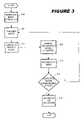
- FIG. 3is a flow chart illustrating an example method for detecting a disturbance in the transmission path of a focused ultrasound beam, in accordance with an embodiment of the invention
- FIG. 4is a flow chart illustrating an example method for determining the range to a particular disturbance in the transmission path of a focused ultrasound beam, in accordance with an embodiment of the invention
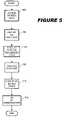
- FIG. 5is a flow chart illustrating a method for processing and displaying data associated with a reflection from a disturbance in the transmission path of a focused ultrasound beam, in accordance with an embodiment of the invention
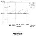
- FIG. 6is a display capture for an oscilloscope that illustrates the reflective signals generated by various disturbances in a transmission path of a focused ultrasound beam
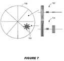
- FIG. 7is a diagram illustrating information related to reflective signals generated by a disturbance in the transmission path of a focused ultrasound beam overlaid on an image of a transducer in order to show the area of the transducer on which the reflective signals are incident;
- FIG. 8Ais a diagram illustrating multiple receive channel traces that show reflective signals generated by one or more disturbances in the transmission path that are received by various transducer array elements.
- FIG. 8Bis a diagram illustrating a single trace comprising composite data from multiple receive channels, such as those illustrated in FIG. 8A .
- FIG. 1is a simplified schematic illustration of an exemplary MRI-guided focused ultrasound thermal treatment system 100 .
- the system 100includes a phased array transducer 102 driven by a controller 106 for emitting a beam of focused ultrasound energy 112 , which converges in a focal zone 104 located in a target tissue mass 105 in a patient 116 .
- the actual geometry of the focal zone 104 within the target tissue mass 105is a function of the shape of the transducer 102 and phasing of the individual transducer elements, which dictate the interaction of the converging ultrasonic waves.
- a MRI system 114is used to acquire images taken along a two-dimensional image plane (or slice) passing through a portion of focal zone 104 .
- the acquired imagesare processed by a processor 108 to monitor the change in temperature of this portion of tissue mass 105 during a sonication.
- the thermal evolution of the focal zone 104is used to verify that a sufficient tissue “kill” temperature is reached, as well as to track which portions of tissue mass 105 have been killed.
- This informationis used by ultrasound controller 106 for positioning ultrasound energy beam 112 (and, thus, focal zone 104 ) in successive sonications of the tissue mass 105 .
- the transmission path of the ultrasound energy beam 112 from the transducer 102 to the focal zone 104be free of disturbances that cause reflections of the beam 112 (or a portion thereof).
- FIG. 2a more detailed view of the ultrasound beam transmission path for system 100 is illustrated in FIG. 2 .
- a transducer 202is located in a bath 204 that is filled with a liquid such as degassed water, which is capable of efficiently transmitting the ultrasound energy beam 210 , and sealed with a thin layer of MylarTM.
- a liquidsuch as degassed water
- a continuous path of liquid(s) separated by non-reflecting mediumsmust be maintained. Therefore, there must also be a tight coupling between the patient's body and the liquid in bath 204 at boundary 216 .
- the coupling at boundary 216can actually comprise multiple layers.
- the interface between bath 204 and patient 206preferably comprises a liquid filled cushion, ultrasound jelly, and water. The interface can preferably be adjusted to fit the patient's body structure to ensure a tight coupling and an efficient transmission path.
- any break in continuity of the transmission path from transducer 202 to focal zone 104can generate reflections of ultrasound energy beam 210 .
- any partial filling of the layers at boundary 216 , air bubbles in any one of the layers, or air gaps between the layerscan create discontinuities causing reflections of the beam 210 .
- partial filling of, or air bubbles in, bath 204can also cause reflections.
- the portion of the ultrasound beam transmission path within the body of the patient 206can also include disturbances that cause reflections.
- this portion of the transmission pathcan contain bones or veins or other ducts in the patient's body containing air pockets or bubbles.
- disturbances in the transmission pathmay exist even if the portion of the transmission path between the transducer 202 and the patient's body is free of discontinuities.
- Reflections from such discontinuities or disturbancescan have multiple negative effects. For example, such reflections can reduce the efficiency of the treatment, cause damage to transducer 202 (i.e., by reflecting the energy in beam 210 back on transducer 202 , causing transducer 202 to overheat), or reflect a portion of ultrasound energy beam 210 to tissue outside of the planned treatment zone 208 . If energy is reflected to unplanned areas in the vicinity of the patient's body, concentrations of undesired energy next to the skin can result, causing skin bums, or even unintended sonication of the patient's organs.
- the flow chart of FIG. 3illustrates an example method for sensing and locating a disturbance in the path of ultrasound energy beam 210 , and is now described with reference to focused ultrasound system 100 in FIG. 1 .
- the ultrasound system 100is switched from a “regular mode” of operation to a “burst mode” of operation in order to sense any disturbances in the acoustic path by sensing delays in echoes of reflected bursts of transmitted energy.
- the “regular mode” of operation for system 100is preferably a continuous, or semi-continuous, wave (CW) mode.
- CW mode of operationhelps to ensure the most efficient transmission of energy and the shortest possible treatment duration.
- burst modea series of narrow bursts of ultrasound energy are transmitted in order to minimize the amount of energy transmitted during the process for sensing and locating any disturbances.
- a short burst of ultrasound energyis transmitted from transducer 102 in step 304 .
- the burstcan, for example, be on the order of twenty micro-seconds long. If transducer 102 comprises an array of transducer elements (which is presumed for the reminder of this detailed description), then the burst transmission preferable involves transmitting a short burst from each transducer array element simultaneously. The burst transmission is preferably focused exactly as planned for the ensuing sonication.
- step 306immediately following the burst transmission, the system 100 switches transducer 102 from transmit to receive mode, whereby the individual transducer elements comprising the transducer 102 are transformed into individual receivers capable of receiving reflected signals (ultrasound waves) generated by any disturbances in the ultrasound energy transmission path.
- the reflected signals (if any) received by the transducer elementsare sampled (step 308 ) and preferably digitized and stored (step 310 ).
- the duration for which the elements of transducer 102 remain in receive mode in step 306is preferably at least equal to the time of flight required for the ultrasound waves transmitted in step 304 to travel from the transducer 102 , to the focal zone 104 , and back to transducer 102 ; i.e., the maximum roundtrip path for a reflected portion of the burst transmission within the transmission path.
- Steps 304 , 306 , 308 and 310which are collectively referred to as a “burst transmit-receive cycle,” are preferably repeated several times during each disturbance sensing process.
- step 312following each burst transmit-receive cycle, the system 100 determines if another burst transmit-receive cycle is required. If so, then the process reverts back to step 304 . If, on the other hand, the disturbance sensing process is complete, and the system 100 switches back to CW operation mode in step 314 .
- the number of burst transmit-receive cycles for each sensing processis equal to the number of transducer array elements comprising transducer 102 . Having the total number of samples equal the total number of transducer elements enables cross correlation of signals from all channels to enhance sensitivity of the detection process and better detect reflections from small disturbances in the wave path.
- a main purpose of performing the steps illustrated in FIG. 3is to determine the range to a reflecting disturbance, as well as the amount of energy reflected by the disturbance (i.e., as measured by the intensity of the reflection).
- FIG. 4is a flow chart illustrating processing of the accumulated sampled data from each burst transmit-receive cycle, in accordance with one embodiment of the invention.
- the datais checked to determine if any reflections were received at any of the transducer elements. If a reflection was received at one or more elements, then, in step 404 , the reflected energy is analyzed in accordance with a predetermined criteria related to the reflection.
- the criteriacan be the “delay time” from transmission to reception of the reflection.
- system 100can be configured to determine, in step 404 , the delay time, which is proportional to the range from the transducer to the disturbance that generated the reflection.
- the range to the disturbance that generated the reflectioncan then be determined from the delay time, since the speed of sound through the various mediums in the ultrasound beam transmission path are known or may otherwise be sufficiently approximated to accurately determine the range information.
- Step 404can also comprise determining the intensity of the reflection. Such information can be used, for example, to determine if system 100 is operating safely.
- step 408information related to received reflections can be displayed for viewing. As can be seen, even if a reflection is not received from a given burst transmit-receive cycle, it still may be beneficial to display information related to the sampled data, because this information can provide a background or noise level against which a reflection can be compared.
- processor 108preferable controls the operation of system 100 using execution instruction stored in memory 118 in conjunction with any data input from an operator. Such data can, for example, be input through a user interface (not shown), such as a graphical user interface.
- processor 108can include an execution area into which execution instructions are loaded from memory 118 . These execution instructions will then cause processor 108 to send commands to controller 106 , which controls the operation of transducer 102 .
- processor 108can be configured to command controller 106 to switch transducer 102 from CW mode operation to burst mode operation. Transducer 102 will then implement steps 304 to 310 for each burst transmit-receive cycle as controlled by controller 106 under the command of processor 108 .
- the sampled data from each step 308is stored by the processor 108 in the memory 118 at each step 310 .
- the processor 108uses the stored data to determine the delay (step 404 ) and the range (step 406 ).
- the processor 108can include a central processing unit such as a microprocessor or micro controller for executing the instructions stored in memory 118 , performing data manipulations, and controlling tasks in system 100 .
- Processor 108can include one or more additional processors, as well.
- additional processorscan include an auxiliary processor to manage input/output, an auxiliary processor to perform floating point mathematical operations, a digital signal processor (DSP) (a special-purpose microprocessor having an architecture suitable for fast execution of signal processing algorithms), a back-end processor (a slave processor subordinate to the main processing system), an additional microprocessor or controller for dual or multiple processor systems, or a coprocessor.
- DSPdigital signal processor
- back-end processora slave processor subordinate to the main processing system
- an additional microprocessor or controllerfor dual or multiple processor systems, or a coprocessor.
- These additional processorsmay be discrete processors or may be built in to the central processing unit.
- the processor 108can be coupled with a communication bus (not shown) that includes a data channel for facilitating information transfer between the processor 108 and the other components of system 100 , such as memory 118 .
- the communication buscan also provides a set of signals required for communication with processor 108 , including a data bus, address bus, and control bus.
- Such a communication buscan comprise any known bus architecture according to promulgated standards.
- bus architecturesinclude, for example, industry standard architecture (ISA), extended industry standard architecture (EISA), Micro Channel Architecture (MCA), peripheral component interconnect (PCI) local bus, standards promulgated by the Institute of Electrical and Electronics Engineers (IEEE) including IEEE 488 general-purpose interface bus (GPIB), IEEE 696/S-100, IEEE P1394, Universal Serial Bus (USB), Access.bus, Apple Desktop Bus (ADB), Concentration Highway Interface (CHI), Fire Wire, Geo Port, or Small Computer Systems Interface (SCSI).
- ISAindustry standard architecture
- EISAextended industry standard architecture
- MCAMicro Channel Architecture
- PCIperipheral component interconnect
- memory 118can be divided into persistent memory and secondary memory.
- the persistent memorycan be configured to provide storage of instructions, data for programs executing on processor 108 , and sampled data from transducer 102 .
- the persistent memoryis typically semiconductor-based memory such as programmable read-only memory (PROM), erasable programmable read-only memory (EPROM), electrically erasable read-only memory (EEPROM), or flash memory (block oriented memory similar to EEPROM).
- PROMprogrammable read-only memory
- EPROMerasable programmable read-only memory
- EEPROMelectrically erasable read-only memory
- flash memoryblock oriented memory similar to EEPROM
- the secondary memorycan be configured to provide storage of instructions and data that are loaded into persistent memory or for temporary data used by processor 108 .
- the secondary memorycan be static random access memory (SRAM), for example, but any appropriate memory type can be used.
- SRAMstatic random access memory
- memory 118 or some portion thereofcan comprise a fixed storage drive and/or a removable drive.
- the systems and methods described hereinare not limited to the architecture illustrated in FIG. 1 .
- some or all of the controller 106 functionalitycan be included in processor 108 and vise versa.
- the architecture illustrated in FIG. 1is by way of example only and should not be seen as limiting the invention in any way.
- the analysis performed by processor 108can include determinations of the delay, as mentioned, as well as determinations of the phase and amplitude of reflected signals relative to each transducer array element. This analysis can take into account the coordinates of the focal zone 104 and can produce a variety of data regarding the transmission path for beam 112 .
- the processing performed by processor 108can allow monitoring and analysis of both the integrative and the individual paths of ultrasound waves transmitted from each transducer array element. By detecting reflections of ultrasound energy beam 112 , processor 108 can determine points along the path where disturbances exist in the transmission media, such as air bubbles or a gap in the coupling layers. With this type of analysis, the integrity of the transmission media can be monitored by system 100 .
- This type of analysiscan also be used to detect air filed veins or bones in the portion 214 of the transmission path inside the patient's body.
- Processor 108can also determine areas of transducer 102 on which high levels of reflected energy are incident. Such analysis in the pre-sonication stage of a treatment can then be used to prevent treatment under conditions that can damage the transducer or result in harm to the patient.
- the flow chart of FIG. 5illustrates one embodiment of the invention for processing and displaying the data received by transducer 102 , so that the presence of disturbances in the ultrasound beam transmission path can be monitored and visualized.
- processor 108accesses the data stored in memory 118 (step 310 ). Although, some or all of the processing can be done in real time as the data is received.
- step 504the amplitude of the received signals for each of multiple receive channels is integrated over a certain time period and displayed on display 110 .
- FIG. 6illustrates a signal capture of a single receive channel on an oscilloscope.
- the signals captured in FIG. 6include a transmitted acoustic signal 602 , with a reflected signal waveform, and for purposes of illustration, a reflected waveform from a MylarTM sheet 604 , a reflected signal waveform from a solid barrier 606 , and secondary reflections 608 .
- the captured signalshave both positive (upper halo) and negative (lower half) phase components.
- System 100preferably comprises multiple receive channels, such as the one illustrated by FIG. 6 .
- system 100can include a receive channel for each transducer array element or the transducer can be divided into sectors each with a corresponding receive channel.
- step 504the received signals for each channel are displayed on display 110 .
- step 506the signals for each receive channel can be overlaid and displayed on a representation of the transducer array, which enables visualization of spots where high amounts of reflected energy is incident on the transducer.
- Traces 702 and 704illustrate the received signal waveforms for a channel corresponding to a transducer sector that does not include reflection spot 708 (channel 702 ) and for a channel that does include reflection spot 708 (channel 704 ).
- trace 704comprises higher amplitude reflections, indicating the reception of higher amount of reflected energy.
- the location of reflection spot 708can then be shown by overlaying traces 702 and 704 on a display of transducer 706 .
- Enhanced contrastis achieved in step 508 by integrating the absolute value of the amplitudes of the signals received by each channel over specific time slices, which correspond to a restricted window of ranges.
- each time slicewill correspond to the time it takes acoustic energy beam 112 to travel a certain distance along the transmission path and for any reflected energy to travel back to transducer 102 .
- the window of possible rangesis bounded at one end by the roundtrip time from transducer 102 to focal spot 104 and back again. At the other end, the window of ranges can be bounded by the time needed for the transducer 102 to be switched to receive mode for receiving any reflections.
- two time slicescan be selected: one to cover the portion of the transmission path within fluid bath 204 ; and one to cover the portion of the transmission path within patient 206 . All the energy reflected within bath 204 would then be integrated and shown as a composite waveform, as would the reflections generated within patient 206 . In practice, however, a finer resolution will likely be needed, which will require the use of many more time slices.
- FIG. 8Aillustrates enhanced signal traces for a 26-channel system using time slices t 1 to t 7 .
- high amounts of reflected energyhave been received in various time slices on channels 1 – 3 and 9 and 10 as well as lesser amounts of energy on various other channels and in various other time slices.
- Displaying this data as a single trace comprising the data from all channels 1 – 26 in step 510is a convenient method for illustrating the ranges to disturbances that even partially reflect acoustic energy beam 112 .
- trace 800 in FIG. 8BSuch a display is illustrated by trace 800 in FIG. 8B .
- the delay determined by processor 108is the delay from transmission of beam 112 to reception of a reflection waveform. If waveforms 802 , 804 , and 806 are reflections, for example, then delays d 1 , d 2 , and d 3 would be the corresponding delays. Delays d 1 , d 2 , and d 3 can then be turned into a range to the particular disturbance that generated each reflection. Combining the display of FIG. 8B with that of FIG. 7 , both the range to a disturbance and the area on which reflected energy therefrom is incident on transducer 706 can be easily visualized by an operator of system 100 .
- a 3D reconstruction of the reflective disturbancecan be generated using an advanced method of multiple delay summation.
- energy wavesreflect in a multiple directions from each point along the surface of the disturbance.
- Directional wave vectorscan be used to represent these reflective waves travelling in different directions. Reflected waves traveling along different wave vectors will fall incident on different transducer array elements.
- the surface of the particular disturbance at a given pointcan be recreated. To ensure that only waves reflected from the point of interested are used in the summation, only waves with delay and phase corresponding to reflections from the particular point are collected and used.
- the vector datais collected and summed for multiple points, i.e., different delays and phases, along the surface. It should be pointed out that the steps illustrated in FIG. 5 can be carried out in a different order, depending on the implementation. Moreover, some or all of the steps can be omitted as required by the particular implementation.
- the systems and methods for sensing, locating and mapping disturbances in an energy beam of a focused ultrasound systemcan be used to identify the location and shape of reflective disturbances in the transmission path of a focused ultrasound system. This information can then be used by the treatment system, or an operator thereof, to ensure that an efficient transmission path that is free of reflective disturbances is maintained from a transducer to a focal zone within a patient. This capability can be used to prevent damage to the transducer or to the patient as well as to reduce the time and number of required sanctions.
Landscapes
- Engineering & Computer Science (AREA)
- Radar, Positioning & Navigation (AREA)
- Remote Sensing (AREA)
- Physics & Mathematics (AREA)
- Health & Medical Sciences (AREA)
- Acoustics & Sound (AREA)
- Biomedical Technology (AREA)
- General Physics & Mathematics (AREA)
- Computer Networks & Wireless Communication (AREA)
- Nuclear Medicine, Radiotherapy & Molecular Imaging (AREA)
- Radiology & Medical Imaging (AREA)
- Life Sciences & Earth Sciences (AREA)
- Animal Behavior & Ethology (AREA)
- General Health & Medical Sciences (AREA)
- Public Health (AREA)
- Veterinary Medicine (AREA)
- Surgical Instruments (AREA)
- Measurement Of Velocity Or Position Using Acoustic Or Ultrasonic Waves (AREA)
- Investigating Or Analyzing Materials By The Use Of Ultrasonic Waves (AREA)
Abstract
Description
Claims (33)
Priority Applications (6)
| Application Number | Priority Date | Filing Date | Title |
|---|---|---|---|
| US10/020,737US7175596B2 (en) | 2001-10-29 | 2001-10-29 | System and method for sensing and locating disturbances in an energy path of a focused ultrasound system |
| DE60227553TDE60227553D1 (en) | 2001-10-29 | 2002-10-28 | DEVICE AND METHOD FOR LOCATING INTERFERENCE IN THE ENERGY SYSTEM OF A FOCUSED ULTRASOUND SYSTEM |
| EP02791949AEP1451593B1 (en) | 2001-10-29 | 2002-10-28 | System and method for sensing and locating disturbances in an energy path of a focused ultrasound system |
| AU2002358250AAU2002358250A1 (en) | 2001-10-29 | 2002-10-28 | System and method for sensing and locating disturbances in an energy path of a focused ultrasound system |
| PCT/IB2002/005799WO2003042707A2 (en) | 2001-10-29 | 2002-10-28 | System and method for sensing and locating disturbances in an energy path of a focused ultrasound system |
| AT02791949TATE400818T1 (en) | 2001-10-29 | 2002-10-28 | DEVICE AND METHOD FOR LOCATION OF FAULTS IN THE ENERGY PATH OF A FOCUSED ULTRASONIC SYSTEM |
Applications Claiming Priority (1)
| Application Number | Priority Date | Filing Date | Title |
|---|---|---|---|
| US10/020,737US7175596B2 (en) | 2001-10-29 | 2001-10-29 | System and method for sensing and locating disturbances in an energy path of a focused ultrasound system |
Publications (2)
| Publication Number | Publication Date |
|---|---|
| US20030083597A1 US20030083597A1 (en) | 2003-05-01 |
| US7175596B2true US7175596B2 (en) | 2007-02-13 |
Family
ID=21800256
Family Applications (1)
| Application Number | Title | Priority Date | Filing Date |
|---|---|---|---|
| US10/020,737Expired - LifetimeUS7175596B2 (en) | 2001-10-29 | 2001-10-29 | System and method for sensing and locating disturbances in an energy path of a focused ultrasound system |
Country Status (6)
| Country | Link |
|---|---|
| US (1) | US7175596B2 (en) |
| EP (1) | EP1451593B1 (en) |
| AT (1) | ATE400818T1 (en) |
| AU (1) | AU2002358250A1 (en) |
| DE (1) | DE60227553D1 (en) |
| WO (1) | WO2003042707A2 (en) |
Cited By (102)
| Publication number | Priority date | Publication date | Assignee | Title |
|---|---|---|---|---|
| US20040122323A1 (en)* | 2002-12-23 | 2004-06-24 | Insightec-Txsonics Ltd | Tissue aberration corrections in ultrasound therapy |
| US20070016039A1 (en)* | 2005-06-21 | 2007-01-18 | Insightec-Image Guided Treatment Ltd. | Controlled, non-linear focused ultrasound treatment |
| US20070054319A1 (en)* | 2005-07-22 | 2007-03-08 | Boyden Edward S | Light-activated cation channel and uses thereof |
| US20070167781A1 (en)* | 2005-11-23 | 2007-07-19 | Insightec Ltd. | Hierarchical Switching in Ultra-High Density Ultrasound Array |
| US20070197918A1 (en)* | 2003-06-02 | 2007-08-23 | Insightec - Image Guided Treatment Ltd. | Endo-cavity focused ultrasound transducer |
| US20070232913A1 (en)* | 2006-01-13 | 2007-10-04 | Mirabilis Medica Inc. | Methods and apparatus for the treatment of menometrorrhagia, endometrial pathology, and cervical neoplasia using high intensity focused ultrasound energy |
| US20080082026A1 (en)* | 2006-04-26 | 2008-04-03 | Rita Schmidt | Focused ultrasound system with far field tail suppression |
| US20080227139A1 (en)* | 2007-02-14 | 2008-09-18 | Karl Deisseroth | System, method and applications involving identification of biological circuits such as neurological characteristics |
| US20080319356A1 (en)* | 2005-09-22 | 2008-12-25 | Cain Charles A | Pulsed cavitational ultrasound therapy |
| US20090036773A1 (en)* | 2007-07-31 | 2009-02-05 | Mirabilis Medica Inc. | Methods and apparatus for engagement and coupling of an intracavitory imaging and high intensity focused ultrasound probe |
| US20090088636A1 (en)* | 2006-01-13 | 2009-04-02 | Mirabilis Medica, Inc. | Apparatus for delivering high intensity focused ultrasound energy to a treatment site internal to a patient's body |
| US20090088623A1 (en)* | 2007-10-01 | 2009-04-02 | Insightec, Ltd. | Motion compensated image-guided focused ultrasound therapy system |
| US20090086183A1 (en)* | 2007-09-28 | 2009-04-02 | Canon Kabushiki Kaisha | Exposure apparatus and device manufacturing method |
| US20090118725A1 (en)* | 2007-11-07 | 2009-05-07 | Mirabilis Medica, Inc. | Hemostatic tissue tunnel generator for inserting treatment apparatus into tissue of a patient |
| US20090118800A1 (en)* | 2007-10-31 | 2009-05-07 | Karl Deisseroth | Implantable optical stimulators |
| US20090118729A1 (en)* | 2007-11-07 | 2009-05-07 | Mirabilis Medica Inc. | Hemostatic spark erosion tissue tunnel generator with integral treatment providing variable volumetric necrotization of tissue |
| US20090287085A1 (en)* | 2008-05-15 | 2009-11-19 | Shmuel Ben-Ezra | Device, system, and method of determining an acoustic contact between an ultrasonic transducer and a body |
| US20100030076A1 (en)* | 2006-08-01 | 2010-02-04 | Kobi Vortman | Systems and Methods for Simultaneously Treating Multiple Target Sites |
| US20100036292A1 (en)* | 2008-08-06 | 2010-02-11 | Mirabilis Medica Inc. | Optimization and feedback control of hifu power deposition through the analysis of detected signal characteristics |
| US20100036291A1 (en)* | 2008-08-06 | 2010-02-11 | Mirabilis Medica Inc. | Optimization and feedback control of hifu power deposition through the frequency analysis of backscattered hifu signals |
| US20100056962A1 (en)* | 2003-05-22 | 2010-03-04 | Kobi Vortman | Acoustic Beam Forming in Phased Arrays Including Large Numbers of Transducer Elements |
| US20100069797A1 (en)* | 2005-09-22 | 2010-03-18 | Cain Charles A | Pulsed cavitational ultrasound therapy |
| US20100106019A1 (en)* | 2008-10-24 | 2010-04-29 | Mirabilis Medica, Inc. | Method and apparatus for feedback control of hifu treatments |
| US20100125193A1 (en)* | 2008-11-19 | 2010-05-20 | Eyal Zadicario | Closed-Loop Clot Lysis |
| US20100145418A1 (en)* | 2007-01-10 | 2010-06-10 | Feng Zhang | System for optical stimulation of target cells |
| US20100179425A1 (en)* | 2009-01-13 | 2010-07-15 | Eyal Zadicario | Systems and methods for controlling ultrasound energy transmitted through non-uniform tissue and cooling of same |
| US20100190229A1 (en)* | 2005-07-22 | 2010-07-29 | Feng Zhang | System for optical stimulation of target cells |
| US20100217161A1 (en)* | 2009-02-25 | 2010-08-26 | Avi Shalgi | Delivery of therapeutic focused energy |
| US20100268088A1 (en)* | 2009-04-17 | 2010-10-21 | Oleg Prus | Multimode ultrasound focusing for medical applications |
| US20100286519A1 (en)* | 2009-05-11 | 2010-11-11 | General Electric Company | Ultrasound system and method to automatically identify and treat adipose tissue |
| US20100286520A1 (en)* | 2009-05-11 | 2010-11-11 | General Electric Company | Ultrasound system and method to determine mechanical properties of a target region |
| US20100286518A1 (en)* | 2009-05-11 | 2010-11-11 | General Electric Company | Ultrasound system and method to deliver therapy based on user defined treatment spaces |
| US20100318002A1 (en)* | 2009-06-10 | 2010-12-16 | Oleg Prus | Acoustic-Feedback Power Control During Focused Ultrasound Delivery |
| US20110034800A1 (en)* | 2009-08-04 | 2011-02-10 | Shuki Vitek | Estimation of alignment parameters in magnetic-resonance-guided ultrasound focusing |
| US20110040190A1 (en)* | 2009-08-17 | 2011-02-17 | Jahnke Russell C | Disposable Acoustic Coupling Medium Container |
| US20110046472A1 (en)* | 2009-08-19 | 2011-02-24 | Rita Schmidt | Techniques for temperature measurement and corrections in long-term magnetic resonance thermometry |
| US20110046475A1 (en)* | 2009-08-24 | 2011-02-24 | Benny Assif | Techniques for correcting temperature measurement in magnetic resonance thermometry |
| US20110054363A1 (en)* | 2009-08-26 | 2011-03-03 | Cain Charles A | Devices and methods for using controlled bubble cloud cavitation in fractionating urinary stones |
| US20110066032A1 (en)* | 2009-08-26 | 2011-03-17 | Shuki Vitek | Asymmetric ultrasound phased-array transducer |
| US20110077555A1 (en)* | 2009-09-29 | 2011-03-31 | Medicis Technologies Corporation | Transducer cartridge for an ultrasound therapy head |
| US20110105998A1 (en)* | 2008-04-23 | 2011-05-05 | The Board Of Trustees Of The Leland Stanford Junio | Systems, methods and compositions for optical stimulation of target cells |
| US20110109309A1 (en)* | 2009-11-10 | 2011-05-12 | Insightec Ltd. | Techniques for correcting measurement artifacts in magnetic resonance thermometry |
| US20110112179A1 (en)* | 2008-05-29 | 2011-05-12 | Airan Raag D | Cell line, system and method for optical control of secondary messengers |
| US20110159562A1 (en)* | 2008-06-17 | 2011-06-30 | Karl Deisseroth | Apparatus and methods for controlling cellular development |
| US20110166632A1 (en)* | 2008-07-08 | 2011-07-07 | Delp Scott L | Materials and approaches for optical stimulation of the peripheral nervous system |
| US20110172653A1 (en)* | 2008-06-17 | 2011-07-14 | Schneider M Bret | Methods, systems and devices for optical stimulation of target cells using an optical transmission element |
| US20120203097A1 (en)* | 2009-10-12 | 2012-08-09 | Koninklijke Philips Electronics N.V. | Magnetic resonance imaging system and method for detecting a gas bubble |
| USRE43901E1 (en) | 2000-11-28 | 2013-01-01 | Insightec Ltd. | Apparatus for controlling thermal dosing in a thermal treatment system |
| US8409099B2 (en) | 2004-08-26 | 2013-04-02 | Insightec Ltd. | Focused ultrasound system for surrounding a body tissue mass and treatment method |
| US8539813B2 (en) | 2009-09-22 | 2013-09-24 | The Regents Of The University Of Michigan | Gel phantoms for testing cavitational ultrasound (histotripsy) transducers |
| US8661873B2 (en) | 2009-10-14 | 2014-03-04 | Insightec Ltd. | Mapping ultrasound transducers |
| US8696722B2 (en) | 2010-11-22 | 2014-04-15 | The Board Of Trustees Of The Leland Stanford Junior University | Optogenetic magnetic resonance imaging |
| US8716447B2 (en) | 2008-11-14 | 2014-05-06 | The Board Of Trustees Of The Leland Stanford Junior University | Optically-based stimulation of target cells and modifications thereto |
| US8845559B2 (en) | 2008-10-03 | 2014-09-30 | Mirabilis Medica Inc. | Method and apparatus for treating tissues with HIFU |
| US8852103B2 (en) | 2011-10-17 | 2014-10-07 | Butterfly Network, Inc. | Transmissive imaging and related apparatus and methods |
| US8926959B2 (en) | 2005-07-22 | 2015-01-06 | The Board Of Trustees Of The Leland Stanford Junior University | System for optical stimulation of target cells |
| US8932237B2 (en) | 2010-04-28 | 2015-01-13 | Insightec, Ltd. | Efficient ultrasound focusing |
| US8932562B2 (en) | 2010-11-05 | 2015-01-13 | The Board Of Trustees Of The Leland Stanford Junior University | Optically controlled CNS dysfunction |
| US8979871B2 (en) | 2009-08-13 | 2015-03-17 | Monteris Medical Corporation | Image-guided therapy of a tissue |
| US9049783B2 (en) | 2012-04-13 | 2015-06-02 | Histosonics, Inc. | Systems and methods for obtaining large creepage isolation on printed circuit boards |
| US9050449B2 (en) | 2008-10-03 | 2015-06-09 | Mirabilis Medica, Inc. | System for treating a volume of tissue with high intensity focused ultrasound |
| US9079940B2 (en) | 2010-03-17 | 2015-07-14 | The Board Of Trustees Of The Leland Stanford Junior University | Light-sensitive ion-passing molecules |
| US9144694B2 (en) | 2011-08-10 | 2015-09-29 | The Regents Of The University Of Michigan | Lesion generation through bone using histotripsy therapy without aberration correction |
| US9175095B2 (en) | 2010-11-05 | 2015-11-03 | The Board Of Trustees Of The Leland Stanford Junior University | Light-activated chimeric opsins and methods of using the same |
| US9238150B2 (en) | 2005-07-22 | 2016-01-19 | The Board Of Trustees Of The Leland Stanford Junior University | Optical tissue interface method and apparatus for stimulating cells |
| US9274099B2 (en) | 2005-07-22 | 2016-03-01 | The Board Of Trustees Of The Leland Stanford Junior University | Screening test drugs to identify their effects on cell membrane voltage-gated ion channel |
| US9284353B2 (en) | 2007-03-01 | 2016-03-15 | The Board Of Trustees Of The Leland Stanford Junior University | Mammalian codon optimized nucleotide sequence that encodes a variant opsin polypeptide derived from Natromonas pharaonis (NpHR) |
| US9333038B2 (en) | 2000-06-15 | 2016-05-10 | Monteris Medical Corporation | Hyperthermia treatment and probe therefore |
| US9365628B2 (en) | 2011-12-16 | 2016-06-14 | The Board Of Trustees Of The Leland Stanford Junior University | Opsin polypeptides and methods of use thereof |
| US9433383B2 (en) | 2014-03-18 | 2016-09-06 | Monteris Medical Corporation | Image-guided therapy of a tissue |
| US9504484B2 (en) | 2014-03-18 | 2016-11-29 | Monteris Medical Corporation | Image-guided therapy of a tissue |
| US9522288B2 (en) | 2010-11-05 | 2016-12-20 | The Board Of Trustees Of The Leland Stanford Junior University | Upconversion of light for use in optogenetic methods |
| US9636380B2 (en) | 2013-03-15 | 2017-05-02 | The Board Of Trustees Of The Leland Stanford Junior University | Optogenetic control of inputs to the ventral tegmental area |
| US9636133B2 (en) | 2012-04-30 | 2017-05-02 | The Regents Of The University Of Michigan | Method of manufacturing an ultrasound system |
| US9667889B2 (en) | 2013-04-03 | 2017-05-30 | Butterfly Network, Inc. | Portable electronic devices with integrated imaging capabilities |
| US9852727B2 (en) | 2010-04-28 | 2017-12-26 | Insightec, Ltd. | Multi-segment ultrasound transducers |
| US9943708B2 (en) | 2009-08-26 | 2018-04-17 | Histosonics, Inc. | Automated control of micromanipulator arm for histotripsy prostate therapy while imaging via ultrasound transducers in real time |
| US9981148B2 (en) | 2010-10-22 | 2018-05-29 | Insightec, Ltd. | Adaptive active cooling during focused ultrasound treatment |
| US9992981B2 (en) | 2010-11-05 | 2018-06-12 | The Board Of Trustees Of The Leland Stanford Junior University | Optogenetic control of reward-related behaviors |
| US10035027B2 (en) | 2007-10-31 | 2018-07-31 | The Board Of Trustees Of The Leland Stanford Junior University | Device and method for ultrasonic neuromodulation via stereotactic frame based technique |
| US10086012B2 (en) | 2010-11-05 | 2018-10-02 | The Board Of Trustees Of The Leland Stanford Junior University | Control and characterization of memory function |
| US10220092B2 (en) | 2013-04-29 | 2019-03-05 | The Board Of Trustees Of The Leland Stanford Junior University | Devices, systems and methods for optogenetic modulation of action potentials in target cells |
| US10219815B2 (en) | 2005-09-22 | 2019-03-05 | The Regents Of The University Of Michigan | Histotripsy for thrombolysis |
| US10293187B2 (en) | 2013-07-03 | 2019-05-21 | Histosonics, Inc. | Histotripsy excitation sequences optimized for bubble cloud formation using shock scattering |
| US10307609B2 (en) | 2013-08-14 | 2019-06-04 | The Board Of Trustees Of The Leland Stanford Junior University | Compositions and methods for controlling pain |
| US10327830B2 (en) | 2015-04-01 | 2019-06-25 | Monteris Medical Corporation | Cryotherapy, thermal therapy, temperature modulation therapy, and probe apparatus therefor |
| US10449395B2 (en) | 2011-12-12 | 2019-10-22 | Insightec, Ltd. | Rib identification for transcostal focused ultrasound surgery |
| US10568516B2 (en) | 2015-06-22 | 2020-02-25 | The Board Of Trustees Of The Leland Stanford Junior University | Methods and devices for imaging and/or optogenetic control of light-responsive neurons |
| US10568307B2 (en) | 2010-11-05 | 2020-02-25 | The Board Of Trustees Of The Leland Stanford Junior University | Stabilized step function opsin proteins and methods of using the same |
| US10675113B2 (en) | 2014-03-18 | 2020-06-09 | Monteris Medical Corporation | Automated therapy of a three-dimensional tissue region |
| US10780298B2 (en) | 2013-08-22 | 2020-09-22 | The Regents Of The University Of Michigan | Histotripsy using very short monopolar ultrasound pulses |
| US10974064B2 (en) | 2013-03-15 | 2021-04-13 | The Board Of Trustees Of The Leland Stanford Junior University | Optogenetic control of behavioral state |
| US11058399B2 (en) | 2012-10-05 | 2021-07-13 | The Regents Of The University Of Michigan | Bubble-induced color doppler feedback during histotripsy |
| US11103723B2 (en) | 2012-02-21 | 2021-08-31 | The Board Of Trustees Of The Leland Stanford Junior University | Methods for treating neurogenic disorders of the pelvic floor |
| US11135454B2 (en) | 2015-06-24 | 2021-10-05 | The Regents Of The University Of Michigan | Histotripsy therapy systems and methods for the treatment of brain tissue |
| US11294165B2 (en) | 2017-03-30 | 2022-04-05 | The Board Of Trustees Of The Leland Stanford Junior University | Modular, electro-optical device for increasing the imaging field of view using time-sequential capture |
| US11432900B2 (en) | 2013-07-03 | 2022-09-06 | Histosonics, Inc. | Articulating arm limiter for cavitational ultrasound therapy system |
| US11648424B2 (en) | 2018-11-28 | 2023-05-16 | Histosonics Inc. | Histotripsy systems and methods |
| US11813485B2 (en) | 2020-01-28 | 2023-11-14 | The Regents Of The University Of Michigan | Systems and methods for histotripsy immunosensitization |
| US12318636B2 (en) | 2022-10-28 | 2025-06-03 | Histosonics, Inc. | Histotripsy systems and methods |
| US12343568B2 (en) | 2020-08-27 | 2025-07-01 | The Regents Of The University Of Michigan | Ultrasound transducer with transmit-receive capability for histotripsy |
| US12402802B2 (en) | 2011-08-31 | 2025-09-02 | Insightec Ltd. | Avoiding MRI-interference with co-existing systems |
Families Citing this family (10)
| Publication number | Priority date | Publication date | Assignee | Title |
|---|---|---|---|---|
| WO2008077096A2 (en)* | 2006-12-19 | 2008-06-26 | Cedars-Sinai Medical Center | Ultrasonic bath to increase tissue perfusion |
| WO2008102293A1 (en)* | 2007-02-23 | 2008-08-28 | Koninklijke Philips Electronics N.V. | An ultrasonic apparatus, a therapeutic system and a method of increasing a workflow |
| CN101754784B (en)* | 2007-06-25 | 2013-11-20 | 国际心脏公司 | Image guided plaque ablation |
| TWI448275B (en)* | 2008-10-24 | 2014-08-11 | Dutch Cardio Llc | A non-invasive system for reducing vascular plaque |
| EP2710586A2 (en)* | 2011-05-18 | 2014-03-26 | Koninklijke Philips N.V. | Spherical ultrasonic hifu transducer with modular cavitation sense element |
| WO2013108152A1 (en)* | 2012-01-16 | 2013-07-25 | Ramot At Tel-Aviv University Ltd | Bypassing obstacles in focused acoustic waves |
| EP3366350B1 (en)* | 2017-02-23 | 2025-07-09 | Theraclion SA | A therapeutic treatment device, a method for defining a setup and a computer program product |
| CN110801267B (en)* | 2019-10-31 | 2022-02-11 | 西安交通大学 | A low-intensity focused vortex sound field assisted ultrasonic fine and efficient thrombolysis system |
| CN113933386A (en)* | 2020-07-13 | 2022-01-14 | 中国矿业大学(北京) | Ultrasonic pulse energy method for dynamically monitoring concrete damage |
| US20250189644A1 (en)* | 2023-12-11 | 2025-06-12 | GE Precision Healthcare LLC | Data transfer on ultrasound probe signal wires |
Citations (8)
| Publication number | Priority date | Publication date | Assignee | Title |
|---|---|---|---|---|
| US4865042A (en) | 1985-08-16 | 1989-09-12 | Hitachi, Ltd. | Ultrasonic irradiation system |
| US4873869A (en) | 1981-10-19 | 1989-10-17 | U.S. Philips Corporation | Device for the scanning of objects by means of ultrasound echography |
| US4958639A (en)* | 1986-10-29 | 1990-09-25 | Olympus Optical Co., Ltd. | Ultrasonic therapeutical apparatus |
| US5485839A (en)* | 1992-02-28 | 1996-01-23 | Kabushiki Kaisha Toshiba | Method and apparatus for ultrasonic wave medical treatment using computed tomography |
| US5520188A (en) | 1994-11-02 | 1996-05-28 | Focus Surgery Inc. | Annular array transducer |
| US5526815A (en) | 1993-01-29 | 1996-06-18 | Siemens Aktiengesellschat | Therapy apparatus for locating and treating a zone located in the body of a life form with acoustic waves |
| US5844140A (en)* | 1996-08-27 | 1998-12-01 | Seale; Joseph B. | Ultrasound beam alignment servo |
| US6042556A (en)* | 1998-09-04 | 2000-03-28 | University Of Washington | Method for determining phase advancement of transducer elements in high intensity focused ultrasound |
Family Cites Families (2)
| Publication number | Priority date | Publication date | Assignee | Title |
|---|---|---|---|---|
| US5526185A (en)* | 1994-06-03 | 1996-06-11 | Xerox Corporation | Method and system for designing color corrected optical systems |
| US6699189B1 (en)* | 2000-12-26 | 2004-03-02 | University Of Rochester | Ultrasound distortion compensation using blind system identification |
- 2001
- 2001-10-29USUS10/020,737patent/US7175596B2/ennot_activeExpired - Lifetime
- 2002
- 2002-10-28EPEP02791949Apatent/EP1451593B1/ennot_activeExpired - Lifetime
- 2002-10-28DEDE60227553Tpatent/DE60227553D1/ennot_activeExpired - Lifetime
- 2002-10-28AUAU2002358250Apatent/AU2002358250A1/ennot_activeAbandoned
- 2002-10-28ATAT02791949Tpatent/ATE400818T1/ennot_activeIP Right Cessation
- 2002-10-28WOPCT/IB2002/005799patent/WO2003042707A2/enactiveIP Right Grant
Patent Citations (8)
| Publication number | Priority date | Publication date | Assignee | Title |
|---|---|---|---|---|
| US4873869A (en) | 1981-10-19 | 1989-10-17 | U.S. Philips Corporation | Device for the scanning of objects by means of ultrasound echography |
| US4865042A (en) | 1985-08-16 | 1989-09-12 | Hitachi, Ltd. | Ultrasonic irradiation system |
| US4958639A (en)* | 1986-10-29 | 1990-09-25 | Olympus Optical Co., Ltd. | Ultrasonic therapeutical apparatus |
| US5485839A (en)* | 1992-02-28 | 1996-01-23 | Kabushiki Kaisha Toshiba | Method and apparatus for ultrasonic wave medical treatment using computed tomography |
| US5526815A (en) | 1993-01-29 | 1996-06-18 | Siemens Aktiengesellschat | Therapy apparatus for locating and treating a zone located in the body of a life form with acoustic waves |
| US5520188A (en) | 1994-11-02 | 1996-05-28 | Focus Surgery Inc. | Annular array transducer |
| US5844140A (en)* | 1996-08-27 | 1998-12-01 | Seale; Joseph B. | Ultrasound beam alignment servo |
| US6042556A (en)* | 1998-09-04 | 2000-03-28 | University Of Washington | Method for determining phase advancement of transducer elements in high intensity focused ultrasound |
Non-Patent Citations (2)
| Title |
|---|
| PCT International Search Report for PCT/IB02/05799, Applicant: Insightec-Image Guided Treatment Ltd., Forms PCT/ISA 210, dated Jun. 2, 2003 (4 pages). |
| PCT Written Opinion of the International Search Authority for PCT/IB02/05799, Applicant: Insightec-Image Guided Treatment Ltd., Form PCT/IPEA/408, dated Jun. 2, 2003 (5 pages). |
Cited By (237)
| Publication number | Priority date | Publication date | Assignee | Title |
|---|---|---|---|---|
| US9333038B2 (en) | 2000-06-15 | 2016-05-10 | Monteris Medical Corporation | Hyperthermia treatment and probe therefore |
| US9387042B2 (en) | 2000-06-15 | 2016-07-12 | Monteris Medical Corporation | Hyperthermia treatment and probe therefor |
| USRE43901E1 (en) | 2000-11-28 | 2013-01-01 | Insightec Ltd. | Apparatus for controlling thermal dosing in a thermal treatment system |
| US20040122323A1 (en)* | 2002-12-23 | 2004-06-24 | Insightec-Txsonics Ltd | Tissue aberration corrections in ultrasound therapy |
| US8088067B2 (en) | 2002-12-23 | 2012-01-03 | Insightec Ltd. | Tissue aberration corrections in ultrasound therapy |
| US8002706B2 (en) | 2003-05-22 | 2011-08-23 | Insightec Ltd. | Acoustic beam forming in phased arrays including large numbers of transducer elements |
| US20100056962A1 (en)* | 2003-05-22 | 2010-03-04 | Kobi Vortman | Acoustic Beam Forming in Phased Arrays Including Large Numbers of Transducer Elements |
| US20070197918A1 (en)* | 2003-06-02 | 2007-08-23 | Insightec - Image Guided Treatment Ltd. | Endo-cavity focused ultrasound transducer |
| US8409099B2 (en) | 2004-08-26 | 2013-04-02 | Insightec Ltd. | Focused ultrasound system for surrounding a body tissue mass and treatment method |
| US20070016039A1 (en)* | 2005-06-21 | 2007-01-18 | Insightec-Image Guided Treatment Ltd. | Controlled, non-linear focused ultrasound treatment |
| US10130828B2 (en) | 2005-06-21 | 2018-11-20 | Insightec Ltd. | Controlled, non-linear focused ultrasound treatment |
| US20100241036A1 (en)* | 2005-06-21 | 2010-09-23 | Insightec, Ltd | Controlled, non-linear focused ultrasound treatment |
| US20100190229A1 (en)* | 2005-07-22 | 2010-07-29 | Feng Zhang | System for optical stimulation of target cells |
| US8926959B2 (en) | 2005-07-22 | 2015-01-06 | The Board Of Trustees Of The Leland Stanford Junior University | System for optical stimulation of target cells |
| US9274099B2 (en) | 2005-07-22 | 2016-03-01 | The Board Of Trustees Of The Leland Stanford Junior University | Screening test drugs to identify their effects on cell membrane voltage-gated ion channel |
| US9238150B2 (en) | 2005-07-22 | 2016-01-19 | The Board Of Trustees Of The Leland Stanford Junior University | Optical tissue interface method and apparatus for stimulating cells |
| US10569099B2 (en) | 2005-07-22 | 2020-02-25 | The Board Of Trustees Of The Leland Stanford Junior University | System for optical stimulation of target cells |
| US20070054319A1 (en)* | 2005-07-22 | 2007-03-08 | Boyden Edward S | Light-activated cation channel and uses thereof |
| US10422803B2 (en) | 2005-07-22 | 2019-09-24 | The Board Of Trustees Of The Leland Stanford Junior University | Light-activated cation channel and uses thereof |
| US9829492B2 (en) | 2005-07-22 | 2017-11-28 | The Board Of Trustees Of The Leland Stanford Junior University | Implantable prosthetic device comprising a cell expressing a channelrhodopsin |
| US10627410B2 (en) | 2005-07-22 | 2020-04-21 | The Board Of Trustees Of The Leland Stanford Junior University | Light-activated cation channel and uses thereof |
| US8906360B2 (en) | 2005-07-22 | 2014-12-09 | The Board Of Trustees Of The Leland Stanford Junior University | Light-activated cation channel and uses thereof |
| US9101690B2 (en) | 2005-07-22 | 2015-08-11 | The Board Of Trustees Of The Leland Stanford Junior University | Light-activated cation channel and uses thereof |
| US10036758B2 (en) | 2005-07-22 | 2018-07-31 | The Board Of Trustees Of The Leland Stanford Junior University | Delivery of a light-activated cation channel into the brain of a subject |
| US9360472B2 (en) | 2005-07-22 | 2016-06-07 | The Board Of Trustees Of The Leland Stanford Junior University | Cell line, system and method for optical-based screening of ion-channel modulators |
| US10046174B2 (en) | 2005-07-22 | 2018-08-14 | The Board Of Trustees Of The Leland Stanford Junior University | System for electrically stimulating target neuronal cells of a living animal in vivo |
| US10094840B2 (en) | 2005-07-22 | 2018-10-09 | The Board Of Trustees Of The Leland Stanford Junior University | Light-activated cation channel and uses thereof |
| US10052497B2 (en) | 2005-07-22 | 2018-08-21 | The Board Of Trustees Of The Leland Stanford Junior University | System for optical stimulation of target cells |
| US20100234273A1 (en)* | 2005-07-22 | 2010-09-16 | The Board Of Trustees Of The Leland Stanford Junior University | Light-activated cation channel and uses thereof |
| US9278159B2 (en) | 2005-07-22 | 2016-03-08 | The Board Of Trustees Of The Leland Stanford Junior University | Light-activated cation channel and uses thereof |
| US10219815B2 (en) | 2005-09-22 | 2019-03-05 | The Regents Of The University Of Michigan | Histotripsy for thrombolysis |
| US9642634B2 (en) | 2005-09-22 | 2017-05-09 | The Regents Of The University Of Michigan | Pulsed cavitational ultrasound therapy |
| US20080319356A1 (en)* | 2005-09-22 | 2008-12-25 | Cain Charles A | Pulsed cavitational ultrasound therapy |
| US8057408B2 (en) | 2005-09-22 | 2011-11-15 | The Regents Of The University Of Michigan | Pulsed cavitational ultrasound therapy |
| US20100069797A1 (en)* | 2005-09-22 | 2010-03-18 | Cain Charles A | Pulsed cavitational ultrasound therapy |
| US12303152B2 (en) | 2005-09-22 | 2025-05-20 | The Regents Of The University Of Michigan | Histotripsy for thrombolysis |
| US12150661B2 (en) | 2005-09-22 | 2024-11-26 | The Regents Of The University Of Michigan | Histotripsy for thrombolysis |
| US11701134B2 (en) | 2005-09-22 | 2023-07-18 | The Regents Of The University Of Michigan | Histotripsy for thrombolysis |
| US11364042B2 (en) | 2005-09-22 | 2022-06-21 | The Regents Of The University Of Michigan | Histotripsy for thrombolysis |
| US20070167781A1 (en)* | 2005-11-23 | 2007-07-19 | Insightec Ltd. | Hierarchical Switching in Ultra-High Density Ultrasound Array |
| US8608672B2 (en) | 2005-11-23 | 2013-12-17 | Insightec Ltd. | Hierarchical switching in ultra-high density ultrasound array |
| US20090088636A1 (en)* | 2006-01-13 | 2009-04-02 | Mirabilis Medica, Inc. | Apparatus for delivering high intensity focused ultrasound energy to a treatment site internal to a patient's body |
| US20070232913A1 (en)* | 2006-01-13 | 2007-10-04 | Mirabilis Medica Inc. | Methods and apparatus for the treatment of menometrorrhagia, endometrial pathology, and cervical neoplasia using high intensity focused ultrasound energy |
| US8057391B2 (en) | 2006-01-13 | 2011-11-15 | Mirabilis Medica, Inc. | Apparatus for delivering high intensity focused ultrasound energy to a treatment site internal to a patient's body |
| US8277379B2 (en) | 2006-01-13 | 2012-10-02 | Mirabilis Medica Inc. | Methods and apparatus for the treatment of menometrorrhagia, endometrial pathology, and cervical neoplasia using high intensity focused ultrasound energy |
| US8235901B2 (en) | 2006-04-26 | 2012-08-07 | Insightec, Ltd. | Focused ultrasound system with far field tail suppression |
| US20080082026A1 (en)* | 2006-04-26 | 2008-04-03 | Rita Schmidt | Focused ultrasound system with far field tail suppression |
| US20100030076A1 (en)* | 2006-08-01 | 2010-02-04 | Kobi Vortman | Systems and Methods for Simultaneously Treating Multiple Target Sites |
| US9187745B2 (en) | 2007-01-10 | 2015-11-17 | The Board Of Trustees Of The Leland Stanford Junior University | System for optical stimulation of target cells |
| US8864805B2 (en) | 2007-01-10 | 2014-10-21 | The Board Of Trustees Of The Leland Stanford Junior University | System for optical stimulation of target cells |
| US8398692B2 (en) | 2007-01-10 | 2013-03-19 | The Board Of Trustees Of The Leland Stanford Junior University | System for optical stimulation of target cells |
| US20100145418A1 (en)* | 2007-01-10 | 2010-06-10 | Feng Zhang | System for optical stimulation of target cells |
| US11007374B2 (en) | 2007-01-10 | 2021-05-18 | The Board Of Trustees Of The Leland Stanford Junior University | System for optical stimulation of target cells |
| US10369378B2 (en) | 2007-01-10 | 2019-08-06 | The Board Of Trustees Of The Leland Stanford Junior University | System for optical stimulation of target cells |
| US10105551B2 (en) | 2007-01-10 | 2018-10-23 | The Board Of Trustees Of The Leland Stanford Junior University | System for optical stimulation of target cells |
| US8401609B2 (en) | 2007-02-14 | 2013-03-19 | The Board Of Trustees Of The Leland Stanford Junior University | System, method and applications involving identification of biological circuits such as neurological characteristics |
| US20080227139A1 (en)* | 2007-02-14 | 2008-09-18 | Karl Deisseroth | System, method and applications involving identification of biological circuits such as neurological characteristics |
| US9693692B2 (en) | 2007-02-14 | 2017-07-04 | The Board Of Trustees Of The Leland Stanford Junior University | System, method and applications involving identification of biological circuits such as neurological characteristics |
| US9855442B2 (en) | 2007-03-01 | 2018-01-02 | The Board Of Trustees Of The Leland Stanford Junior University | Method for optically controlling a neuron with a mammalian codon optimized nucleotide sequence that encodes a variant opsin polypeptide derived from natromonas pharaonis (NpHR) |
| US9284353B2 (en) | 2007-03-01 | 2016-03-15 | The Board Of Trustees Of The Leland Stanford Junior University | Mammalian codon optimized nucleotide sequence that encodes a variant opsin polypeptide derived from Natromonas pharaonis (NpHR) |
| US9757587B2 (en) | 2007-03-01 | 2017-09-12 | The Board Of Trustees Of The Leland Stanford Junior University | Optogenetic method for generating an inhibitory current in a mammalian neuron |
| US10589123B2 (en) | 2007-03-01 | 2020-03-17 | The Board Of Trustees Of The Leland Stanford Junior University | Systems, methods and compositions for optical stimulation of target cells |
| US8052604B2 (en) | 2007-07-31 | 2011-11-08 | Mirabilis Medica Inc. | Methods and apparatus for engagement and coupling of an intracavitory imaging and high intensity focused ultrasound probe |
| US20090036773A1 (en)* | 2007-07-31 | 2009-02-05 | Mirabilis Medica Inc. | Methods and apparatus for engagement and coupling of an intracavitory imaging and high intensity focused ultrasound probe |
| US20090086183A1 (en)* | 2007-09-28 | 2009-04-02 | Canon Kabushiki Kaisha | Exposure apparatus and device manufacturing method |
| US20090088623A1 (en)* | 2007-10-01 | 2009-04-02 | Insightec, Ltd. | Motion compensated image-guided focused ultrasound therapy system |
| US8251908B2 (en) | 2007-10-01 | 2012-08-28 | Insightec Ltd. | Motion compensated image-guided focused ultrasound therapy system |
| US8548561B2 (en) | 2007-10-01 | 2013-10-01 | Insightec Ltd. | Motion compensated image-guided focused ultrasound therapy system |
| US10434327B2 (en) | 2007-10-31 | 2019-10-08 | The Board Of Trustees Of The Leland Stanford Junior University | Implantable optical stimulators |
| US10426970B2 (en) | 2007-10-31 | 2019-10-01 | The Board Of Trustees Of The Leland Stanford Junior University | Implantable optical stimulators |
| US10035027B2 (en) | 2007-10-31 | 2018-07-31 | The Board Of Trustees Of The Leland Stanford Junior University | Device and method for ultrasonic neuromodulation via stereotactic frame based technique |
| US20090118800A1 (en)* | 2007-10-31 | 2009-05-07 | Karl Deisseroth | Implantable optical stimulators |
| US8439907B2 (en) | 2007-11-07 | 2013-05-14 | Mirabilis Medica Inc. | Hemostatic tissue tunnel generator for inserting treatment apparatus into tissue of a patient |
| US20090118729A1 (en)* | 2007-11-07 | 2009-05-07 | Mirabilis Medica Inc. | Hemostatic spark erosion tissue tunnel generator with integral treatment providing variable volumetric necrotization of tissue |
| US20090118725A1 (en)* | 2007-11-07 | 2009-05-07 | Mirabilis Medica, Inc. | Hemostatic tissue tunnel generator for inserting treatment apparatus into tissue of a patient |
| US8187270B2 (en) | 2007-11-07 | 2012-05-29 | Mirabilis Medica Inc. | Hemostatic spark erosion tissue tunnel generator with integral treatment providing variable volumetric necrotization of tissue |
| US8603790B2 (en) | 2008-04-23 | 2013-12-10 | The Board Of Trustees Of The Leland Stanford Junior University | Systems, methods and compositions for optical stimulation of target cells |
| US9249200B2 (en) | 2008-04-23 | 2016-02-02 | The Board Of Trustees Of The Leland Stanford Junior University | Expression vector comprising a nucleotide sequence encoding a Volvox carteri light-activated ion channel protein (VChR1) and implantable device thereof |
| US20110105998A1 (en)* | 2008-04-23 | 2011-05-05 | The Board Of Trustees Of The Leland Stanford Junio | Systems, methods and compositions for optical stimulation of target cells |
| US10350430B2 (en) | 2008-04-23 | 2019-07-16 | The Board Of Trustees Of The Leland Stanford Junior University | System comprising a nucleotide sequence encoding a volvox carteri light-activated ion channel protein (VCHR1) |
| US9394347B2 (en) | 2008-04-23 | 2016-07-19 | The Board Of Trustees Of The Leland Stanford Junior University | Methods for treating parkinson's disease by optically stimulating target cells |
| US8815582B2 (en) | 2008-04-23 | 2014-08-26 | The Board Of Trustees Of The Leland Stanford Junior University | Mammalian cell expressing Volvox carteri light-activated ion channel protein (VChR1) |
| US9878176B2 (en) | 2008-04-23 | 2018-01-30 | The Board Of Trustees Of The Leland Stanford Junior University | System utilizing Volvox carteri light-activated ion channel protein (VChR1) for optical stimulation of target cells |
| US20090287085A1 (en)* | 2008-05-15 | 2009-11-19 | Shmuel Ben-Ezra | Device, system, and method of determining an acoustic contact between an ultrasonic transducer and a body |
| US8962589B2 (en) | 2008-05-29 | 2015-02-24 | The Board Of Trustees Of The Leland Stanford Junior University | Cell line, system and method for optical control of secondary messengers |
| US9453215B2 (en) | 2008-05-29 | 2016-09-27 | The Board Of Trustees Of The Leland Stanford Junior University | Cell line, system and method for optical control of secondary messengers |
| US20110112179A1 (en)* | 2008-05-29 | 2011-05-12 | Airan Raag D | Cell line, system and method for optical control of secondary messengers |
| US8729040B2 (en) | 2008-05-29 | 2014-05-20 | The Board Of Trustees Of The Leland Stanford Junior University | Cell line, system and method for optical control of secondary messengers |
| US20110172653A1 (en)* | 2008-06-17 | 2011-07-14 | Schneider M Bret | Methods, systems and devices for optical stimulation of target cells using an optical transmission element |
| US8956363B2 (en) | 2008-06-17 | 2015-02-17 | The Board Of Trustees Of The Leland Stanford Junior University | Methods, systems and devices for optical stimulation of target cells using an optical transmission element |
| US10711242B2 (en) | 2008-06-17 | 2020-07-14 | The Board Of Trustees Of The Leland Stanford Junior University | Apparatus and methods for controlling cellular development |
| US20110159562A1 (en)* | 2008-06-17 | 2011-06-30 | Karl Deisseroth | Apparatus and methods for controlling cellular development |
| US9084885B2 (en) | 2008-06-17 | 2015-07-21 | The Board Of Trustees Of The Leland Stanford Junior University | Methods, systems and devices for optical stimulation of target cells using an optical transmission element |
| US9308392B2 (en) | 2008-07-08 | 2016-04-12 | The Board Of Trustees Of The Leland Stanford Junior University | Materials and approaches for optical stimulation of the peripheral nervous system |
| US10583309B2 (en) | 2008-07-08 | 2020-03-10 | The Board Of Trustees Of The Leland Stanford Junior University | Materials and approaches for optical stimulation of the peripheral nervous system |
| US20110166632A1 (en)* | 2008-07-08 | 2011-07-07 | Delp Scott L | Materials and approaches for optical stimulation of the peripheral nervous system |
| US9101759B2 (en) | 2008-07-08 | 2015-08-11 | The Board Of Trustees Of The Leland Stanford Junior University | Materials and approaches for optical stimulation of the peripheral nervous system |
| US10226646B2 (en) | 2008-08-06 | 2019-03-12 | Mirabillis Medica, Inc. | Optimization and feedback control of HIFU power deposition through the analysis of detected signal characteristics |
| US20100036292A1 (en)* | 2008-08-06 | 2010-02-11 | Mirabilis Medica Inc. | Optimization and feedback control of hifu power deposition through the analysis of detected signal characteristics |
| US9248318B2 (en) | 2008-08-06 | 2016-02-02 | Mirabilis Medica Inc. | Optimization and feedback control of HIFU power deposition through the analysis of detected signal characteristics |
| US20100036291A1 (en)* | 2008-08-06 | 2010-02-11 | Mirabilis Medica Inc. | Optimization and feedback control of hifu power deposition through the frequency analysis of backscattered hifu signals |
| US8216161B2 (en) | 2008-08-06 | 2012-07-10 | Mirabilis Medica Inc. | Optimization and feedback control of HIFU power deposition through the frequency analysis of backscattered HIFU signals |
| US9050449B2 (en) | 2008-10-03 | 2015-06-09 | Mirabilis Medica, Inc. | System for treating a volume of tissue with high intensity focused ultrasound |
| US8845559B2 (en) | 2008-10-03 | 2014-09-30 | Mirabilis Medica Inc. | Method and apparatus for treating tissues with HIFU |
| US9770605B2 (en) | 2008-10-03 | 2017-09-26 | Mirabilis Medica, Inc. | System for treating a volume of tissue with high intensity focused ultrasound |
| US20100106019A1 (en)* | 2008-10-24 | 2010-04-29 | Mirabilis Medica, Inc. | Method and apparatus for feedback control of hifu treatments |
| US8480600B2 (en) | 2008-10-24 | 2013-07-09 | Mirabilis Medica Inc. | Method and apparatus for feedback control of HIFU treatments |
| US10071132B2 (en) | 2008-11-14 | 2018-09-11 | The Board Of Trustees Of The Leland Stanford Junior University | Optically-based stimulation of target cells and modifications thereto |
| US10064912B2 (en) | 2008-11-14 | 2018-09-04 | The Board Of Trustees Of The Leland Stanford Junior University | Optically-based stimulation of target cells and modifications thereto |
| US8716447B2 (en) | 2008-11-14 | 2014-05-06 | The Board Of Trustees Of The Leland Stanford Junior University | Optically-based stimulation of target cells and modifications thereto |
| US9458208B2 (en) | 2008-11-14 | 2016-10-04 | The Board Of Trustees Of The Leland Stanford Junior University | Optically-based stimulation of target cells and modifications thereto |
| US9309296B2 (en) | 2008-11-14 | 2016-04-12 | The Board Of Trustees Of The Leland Stanford Junior University | Optically-based stimulation of target cells and modifications thereto |
| US8425424B2 (en) | 2008-11-19 | 2013-04-23 | Inightee Ltd. | Closed-loop clot lysis |
| US20100125193A1 (en)* | 2008-11-19 | 2010-05-20 | Eyal Zadicario | Closed-Loop Clot Lysis |
| US20100179425A1 (en)* | 2009-01-13 | 2010-07-15 | Eyal Zadicario | Systems and methods for controlling ultrasound energy transmitted through non-uniform tissue and cooling of same |
| US20100217161A1 (en)* | 2009-02-25 | 2010-08-26 | Avi Shalgi | Delivery of therapeutic focused energy |
| US8617073B2 (en) | 2009-04-17 | 2013-12-31 | Insightec Ltd. | Focusing ultrasound into the brain through the skull by utilizing both longitudinal and shear waves |
| US20100268088A1 (en)* | 2009-04-17 | 2010-10-21 | Oleg Prus | Multimode ultrasound focusing for medical applications |
| US20100286519A1 (en)* | 2009-05-11 | 2010-11-11 | General Electric Company | Ultrasound system and method to automatically identify and treat adipose tissue |
| US20100286520A1 (en)* | 2009-05-11 | 2010-11-11 | General Electric Company | Ultrasound system and method to determine mechanical properties of a target region |
| US20100286518A1 (en)* | 2009-05-11 | 2010-11-11 | General Electric Company | Ultrasound system and method to deliver therapy based on user defined treatment spaces |
| US20100318002A1 (en)* | 2009-06-10 | 2010-12-16 | Oleg Prus | Acoustic-Feedback Power Control During Focused Ultrasound Delivery |
| US9623266B2 (en) | 2009-08-04 | 2017-04-18 | Insightec Ltd. | Estimation of alignment parameters in magnetic-resonance-guided ultrasound focusing |
| US20110034800A1 (en)* | 2009-08-04 | 2011-02-10 | Shuki Vitek | Estimation of alignment parameters in magnetic-resonance-guided ultrasound focusing |
| US9271794B2 (en) | 2009-08-13 | 2016-03-01 | Monteris Medical Corporation | Monitoring and noise masking of thermal therapy |
| US10188462B2 (en) | 2009-08-13 | 2019-01-29 | Monteris Medical Corporation | Image-guided therapy of a tissue |
| US8979871B2 (en) | 2009-08-13 | 2015-03-17 | Monteris Medical Corporation | Image-guided therapy of a tissue |
| US9211157B2 (en) | 2009-08-13 | 2015-12-15 | Monteris Medical Corporation | Probe driver |
| US9510909B2 (en) | 2009-08-13 | 2016-12-06 | Monteris Medical Corporation | Image-guide therapy of a tissue |
| US10610317B2 (en) | 2009-08-13 | 2020-04-07 | Monteris Medical Corporation | Image-guided therapy of a tissue |
| US20110040190A1 (en)* | 2009-08-17 | 2011-02-17 | Jahnke Russell C | Disposable Acoustic Coupling Medium Container |
| US9061131B2 (en) | 2009-08-17 | 2015-06-23 | Histosonics, Inc. | Disposable acoustic coupling medium container |
| US9526923B2 (en) | 2009-08-17 | 2016-12-27 | Histosonics, Inc. | Disposable acoustic coupling medium container |
| US9289154B2 (en) | 2009-08-19 | 2016-03-22 | Insightec Ltd. | Techniques for temperature measurement and corrections in long-term magnetic resonance thermometry |
| US20110046472A1 (en)* | 2009-08-19 | 2011-02-24 | Rita Schmidt | Techniques for temperature measurement and corrections in long-term magnetic resonance thermometry |
| US20110046475A1 (en)* | 2009-08-24 | 2011-02-24 | Benny Assif | Techniques for correcting temperature measurement in magnetic resonance thermometry |
| US9177543B2 (en) | 2009-08-26 | 2015-11-03 | Insightec Ltd. | Asymmetric ultrasound phased-array transducer for dynamic beam steering to ablate tissues in MRI |
| US20110054363A1 (en)* | 2009-08-26 | 2011-03-03 | Cain Charles A | Devices and methods for using controlled bubble cloud cavitation in fractionating urinary stones |
| US20110066032A1 (en)* | 2009-08-26 | 2011-03-17 | Shuki Vitek | Asymmetric ultrasound phased-array transducer |
| US9943708B2 (en) | 2009-08-26 | 2018-04-17 | Histosonics, Inc. | Automated control of micromanipulator arm for histotripsy prostate therapy while imaging via ultrasound transducers in real time |
| US9901753B2 (en) | 2009-08-26 | 2018-02-27 | The Regents Of The University Of Michigan | Ultrasound lithotripsy and histotripsy for using controlled bubble cloud cavitation in fractionating urinary stones |
| US8539813B2 (en) | 2009-09-22 | 2013-09-24 | The Regents Of The University Of Michigan | Gel phantoms for testing cavitational ultrasound (histotripsy) transducers |
| US20110077555A1 (en)* | 2009-09-29 | 2011-03-31 | Medicis Technologies Corporation | Transducer cartridge for an ultrasound therapy head |
| US20110077557A1 (en)* | 2009-09-29 | 2011-03-31 | Medicis Technologies Corporation | Medical ultrasound device with liquid dispensing device coupled to a therapy head |
| US8425435B2 (en) | 2009-09-29 | 2013-04-23 | Liposonix, Inc. | Transducer cartridge for an ultrasound therapy head |
| US10010722B2 (en) | 2009-09-29 | 2018-07-03 | Liposonix, Inc. | Transducer cartridge for an ultrasound therapy head |
| US8932238B2 (en) | 2009-09-29 | 2015-01-13 | Liposonix, Inc. | Medical ultrasound device with liquid dispensing device coupled to a therapy head |
| EP2488857A1 (en)* | 2009-10-12 | 2012-08-22 | Koninklijke Philips Electronics N.V. | Magnetic resonance imaging system and method for detecting a gas bubble |
| US20120203097A1 (en)* | 2009-10-12 | 2012-08-09 | Koninklijke Philips Electronics N.V. | Magnetic resonance imaging system and method for detecting a gas bubble |
| US9412357B2 (en) | 2009-10-14 | 2016-08-09 | Insightec Ltd. | Mapping ultrasound transducers |
| US8661873B2 (en) | 2009-10-14 | 2014-03-04 | Insightec Ltd. | Mapping ultrasound transducers |
| US20110109309A1 (en)* | 2009-11-10 | 2011-05-12 | Insightec Ltd. | Techniques for correcting measurement artifacts in magnetic resonance thermometry |
| US9541621B2 (en) | 2009-11-10 | 2017-01-10 | Insightec, Ltd. | Techniques for correcting measurement artifacts in magnetic resonance thermometry |
| US8368401B2 (en) | 2009-11-10 | 2013-02-05 | Insightec Ltd. | Techniques for correcting measurement artifacts in magnetic resonance thermometry |
| US9079940B2 (en) | 2010-03-17 | 2015-07-14 | The Board Of Trustees Of The Leland Stanford Junior University | Light-sensitive ion-passing molecules |
| US9604073B2 (en) | 2010-03-17 | 2017-03-28 | The Board Of Trustees Of The Leland Stanford Junior University | Light-sensitive ion-passing molecules |
| US9359449B2 (en) | 2010-03-17 | 2016-06-07 | The Board Of Trustees Of The Leland Stanford Junior University | Light-sensitive ion-passing molecules |
| US9249234B2 (en) | 2010-03-17 | 2016-02-02 | The Board Of Trustees Of The Leland Stanford Junior University | Light-sensitive ion-passing molecules |
| US8932237B2 (en) | 2010-04-28 | 2015-01-13 | Insightec, Ltd. | Efficient ultrasound focusing |
| US9852727B2 (en) | 2010-04-28 | 2017-12-26 | Insightec, Ltd. | Multi-segment ultrasound transducers |
| US9981148B2 (en) | 2010-10-22 | 2018-05-29 | Insightec, Ltd. | Adaptive active cooling during focused ultrasound treatment |
| US9175095B2 (en) | 2010-11-05 | 2015-11-03 | The Board Of Trustees Of The Leland Stanford Junior University | Light-activated chimeric opsins and methods of using the same |
| US10086012B2 (en) | 2010-11-05 | 2018-10-02 | The Board Of Trustees Of The Leland Stanford Junior University | Control and characterization of memory function |
| US9522288B2 (en) | 2010-11-05 | 2016-12-20 | The Board Of Trustees Of The Leland Stanford Junior University | Upconversion of light for use in optogenetic methods |
| US9340589B2 (en) | 2010-11-05 | 2016-05-17 | The Board Of Trustees Of The Leland Stanford Junior University | Light-activated chimeric opsins and methods of using the same |
| US9968652B2 (en) | 2010-11-05 | 2018-05-15 | The Board Of Trustees Of The Leland Stanford Junior University | Optically-controlled CNS dysfunction |
| US10568307B2 (en) | 2010-11-05 | 2020-02-25 | The Board Of Trustees Of The Leland Stanford Junior University | Stabilized step function opsin proteins and methods of using the same |
| US9992981B2 (en) | 2010-11-05 | 2018-06-12 | The Board Of Trustees Of The Leland Stanford Junior University | Optogenetic control of reward-related behaviors |
| US10252076B2 (en) | 2010-11-05 | 2019-04-09 | The Board Of Trustees Of The Leland Stanford Junior University | Upconversion of light for use in optogenetic methods |
| US10196431B2 (en) | 2010-11-05 | 2019-02-05 | The Board Of Trustees Of The Leland Stanford Junior University | Light-activated chimeric opsins and methods of using the same |
| US9421258B2 (en) | 2010-11-05 | 2016-08-23 | The Board Of Trustees Of The Leland Stanford Junior University | Optically controlled CNS dysfunction |
| US8932562B2 (en) | 2010-11-05 | 2015-01-13 | The Board Of Trustees Of The Leland Stanford Junior University | Optically controlled CNS dysfunction |
| US9850290B2 (en) | 2010-11-05 | 2017-12-26 | The Board Of Trustees Of The Leland Stanford Junior University | Light-activated chimeric opsins and methods of using the same |
| US9271674B2 (en) | 2010-11-22 | 2016-03-01 | The Board Of Trustees Of The Leland Stanford Junior University | Optogenetic magnetic resonance imaging |
| US10914803B2 (en) | 2010-11-22 | 2021-02-09 | The Board Of Trustees Of The Leland Stanford Junior University | Optogenetic magnetic resonance imaging |
| US10371776B2 (en) | 2010-11-22 | 2019-08-06 | The Board Of Trustees Of The Leland Stanford Junior University | Optogenetic magnetic resonance imaging |
| US8696722B2 (en) | 2010-11-22 | 2014-04-15 | The Board Of Trustees Of The Leland Stanford Junior University | Optogenetic magnetic resonance imaging |
| US9615789B2 (en) | 2010-11-22 | 2017-04-11 | The Board Of Trustees Of The Leland Stanford Junior University | Optogenetic magnetic resonance imaging |
| US8834546B2 (en) | 2010-11-22 | 2014-09-16 | The Board Of Trustees Of The Leland Stanford Junior University | Optogenetic magnetic resonance imaging |
| US10018695B2 (en) | 2010-11-22 | 2018-07-10 | The Board Of Trustees Of The Leland Stanford Junior University | Optogenetic magnetic resonance imaging |
| US9144694B2 (en) | 2011-08-10 | 2015-09-29 | The Regents Of The University Of Michigan | Lesion generation through bone using histotripsy therapy without aberration correction |
| US10071266B2 (en) | 2011-08-10 | 2018-09-11 | The Regents Of The University Of Michigan | Lesion generation through bone using histotripsy therapy without aberration correction |
| US12402802B2 (en) | 2011-08-31 | 2025-09-02 | Insightec Ltd. | Avoiding MRI-interference with co-existing systems |
| US9028412B2 (en) | 2011-10-17 | 2015-05-12 | Butterfly Network, Inc. | Transmissive imaging and related apparatus and methods |
| US9033884B2 (en) | 2011-10-17 | 2015-05-19 | Butterfly Network, Inc. | Transmissive imaging and related apparatus and methods |
| US9247924B2 (en) | 2011-10-17 | 2016-02-02 | Butterfly Networks, Inc. | Transmissive imaging and related apparatus and methods |
| US8852103B2 (en) | 2011-10-17 | 2014-10-07 | Butterfly Network, Inc. | Transmissive imaging and related apparatus and methods |
| US9268015B2 (en) | 2011-10-17 | 2016-02-23 | Butterfly Network, Inc. | Image-guided high intensity focused ultrasound and related apparatus and methods |
| US9155521B2 (en) | 2011-10-17 | 2015-10-13 | Butterfly Network, Inc. | Transmissive imaging and related apparatus and methods |
| US9022936B2 (en) | 2011-10-17 | 2015-05-05 | Butterfly Network, Inc. | Transmissive imaging and related apparatus and methods |
| US9149255B2 (en) | 2011-10-17 | 2015-10-06 | Butterfly Network, Inc. | Image-guided high intensity focused ultrasound and related apparatus and methods |
| US9268014B2 (en) | 2011-10-17 | 2016-02-23 | Butterfly Network, Inc. | Transmissive imaging and related apparatus and methods |
| US9198637B2 (en) | 2011-10-17 | 2015-12-01 | Butterfly Network, Inc. | Transmissive imaging and related apparatus and methods |
| US10449395B2 (en) | 2011-12-12 | 2019-10-22 | Insightec, Ltd. | Rib identification for transcostal focused ultrasound surgery |
| US10087223B2 (en) | 2011-12-16 | 2018-10-02 | The Board Of Trustees Of The Leland Stanford Junior University | Opsin polypeptides and methods of use thereof |
| US9969783B2 (en) | 2011-12-16 | 2018-05-15 | The Board Of Trustees Of The Leland Stanford Junior University | Opsin polypeptides and methods of use thereof |
| US9840541B2 (en) | 2011-12-16 | 2017-12-12 | The Board Of Trustees Of The Leland Stanford Junior University | Opsin polypeptides and methods of use thereof |
| US9505817B2 (en) | 2011-12-16 | 2016-11-29 | The Board Of Trustees Of The Leland Stanford Junior University | Opsin polypeptides and methods of use thereof |
| US10538560B2 (en) | 2011-12-16 | 2020-01-21 | The Board Of Trustees Of The Leland Stanford Junior University | Opsin polypeptides and methods of use thereof |
| US9365628B2 (en) | 2011-12-16 | 2016-06-14 | The Board Of Trustees Of The Leland Stanford Junior University | Opsin polypeptides and methods of use thereof |
| US11103723B2 (en) | 2012-02-21 | 2021-08-31 | The Board Of Trustees Of The Leland Stanford Junior University | Methods for treating neurogenic disorders of the pelvic floor |
| US9049783B2 (en) | 2012-04-13 | 2015-06-02 | Histosonics, Inc. | Systems and methods for obtaining large creepage isolation on printed circuit boards |
| US9636133B2 (en) | 2012-04-30 | 2017-05-02 | The Regents Of The University Of Michigan | Method of manufacturing an ultrasound system |
| US10548678B2 (en) | 2012-06-27 | 2020-02-04 | Monteris Medical Corporation | Method and device for effecting thermal therapy of a tissue |
| US11058399B2 (en) | 2012-10-05 | 2021-07-13 | The Regents Of The University Of Michigan | Bubble-induced color doppler feedback during histotripsy |
| US9636380B2 (en) | 2013-03-15 | 2017-05-02 | The Board Of Trustees Of The Leland Stanford Junior University | Optogenetic control of inputs to the ventral tegmental area |
| US10974064B2 (en) | 2013-03-15 | 2021-04-13 | The Board Of Trustees Of The Leland Stanford Junior University | Optogenetic control of behavioral state |
| US9667889B2 (en) | 2013-04-03 | 2017-05-30 | Butterfly Network, Inc. | Portable electronic devices with integrated imaging capabilities |
| US10220092B2 (en) | 2013-04-29 | 2019-03-05 | The Board Of Trustees Of The Leland Stanford Junior University | Devices, systems and methods for optogenetic modulation of action potentials in target cells |
| US10293187B2 (en) | 2013-07-03 | 2019-05-21 | Histosonics, Inc. | Histotripsy excitation sequences optimized for bubble cloud formation using shock scattering |
| US11432900B2 (en) | 2013-07-03 | 2022-09-06 | Histosonics, Inc. | Articulating arm limiter for cavitational ultrasound therapy system |
| US10307609B2 (en) | 2013-08-14 | 2019-06-04 | The Board Of Trustees Of The Leland Stanford Junior University | Compositions and methods for controlling pain |
| US11819712B2 (en) | 2013-08-22 | 2023-11-21 | The Regents Of The University Of Michigan | Histotripsy using very short ultrasound pulses |
| US10780298B2 (en) | 2013-08-22 | 2020-09-22 | The Regents Of The University Of Michigan | Histotripsy using very short monopolar ultrasound pulses |
| US12350525B2 (en) | 2013-08-22 | 2025-07-08 | The Regents Of The University Of Michigan | Histotripsy using very short ultrasound pulses |
| US9492121B2 (en) | 2014-03-18 | 2016-11-15 | Monteris Medical Corporation | Image-guided therapy of a tissue |
| US9486170B2 (en) | 2014-03-18 | 2016-11-08 | Monteris Medical Corporation | Image-guided therapy of a tissue |
| US9700342B2 (en) | 2014-03-18 | 2017-07-11 | Monteris Medical Corporation | Image-guided therapy of a tissue |
| US9504484B2 (en) | 2014-03-18 | 2016-11-29 | Monteris Medical Corporation | Image-guided therapy of a tissue |
| US10675113B2 (en) | 2014-03-18 | 2020-06-09 | Monteris Medical Corporation | Automated therapy of a three-dimensional tissue region |
| US9433383B2 (en) | 2014-03-18 | 2016-09-06 | Monteris Medical Corporation | Image-guided therapy of a tissue |
| US10092367B2 (en) | 2014-03-18 | 2018-10-09 | Monteris Medical Corporation | Image-guided therapy of a tissue |
| US10342632B2 (en) | 2014-03-18 | 2019-07-09 | Monteris Medical Corporation | Image-guided therapy of a tissue |
| US11672583B2 (en) | 2015-04-01 | 2023-06-13 | Monteris Medical Corporation | Cryotherapy, thermal therapy, temperature modulation therapy, and probe apparatus therefor |
| US10327830B2 (en) | 2015-04-01 | 2019-06-25 | Monteris Medical Corporation | Cryotherapy, thermal therapy, temperature modulation therapy, and probe apparatus therefor |
| US10568516B2 (en) | 2015-06-22 | 2020-02-25 | The Board Of Trustees Of The Leland Stanford Junior University | Methods and devices for imaging and/or optogenetic control of light-responsive neurons |
| US12220602B2 (en) | 2015-06-24 | 2025-02-11 | The Regents Of The University Of Michigan | Histotripsy therapy systems and methods for the treatment of brain tissue |
| US11135454B2 (en) | 2015-06-24 | 2021-10-05 | The Regents Of The University Of Michigan | Histotripsy therapy systems and methods for the treatment of brain tissue |
| US11294165B2 (en) | 2017-03-30 | 2022-04-05 | The Board Of Trustees Of The Leland Stanford Junior University | Modular, electro-optical device for increasing the imaging field of view using time-sequential capture |
| US11648424B2 (en) | 2018-11-28 | 2023-05-16 | Histosonics Inc. | Histotripsy systems and methods |
| US11980778B2 (en) | 2018-11-28 | 2024-05-14 | Histosonics, Inc. | Histotripsy systems and methods |
| US11813484B2 (en) | 2018-11-28 | 2023-11-14 | Histosonics, Inc. | Histotripsy systems and methods |
| US12420118B2 (en) | 2018-11-28 | 2025-09-23 | Histosonics, Inc. | Histotripsy systems and methods |
| US11813485B2 (en) | 2020-01-28 | 2023-11-14 | The Regents Of The University Of Michigan | Systems and methods for histotripsy immunosensitization |
| US12343568B2 (en) | 2020-08-27 | 2025-07-01 | The Regents Of The University Of Michigan | Ultrasound transducer with transmit-receive capability for histotripsy |
| US12318636B2 (en) | 2022-10-28 | 2025-06-03 | Histosonics, Inc. | Histotripsy systems and methods |
| US12390665B1 (en) | 2022-10-28 | 2025-08-19 | Histosonics, Inc. | Histotripsy systems and methods |
Also Published As
| Publication number | Publication date |
|---|---|
| ATE400818T1 (en) | 2008-07-15 |
| WO2003042707A2 (en) | 2003-05-22 |
| EP1451593A2 (en) | 2004-09-01 |
| WO2003042707A3 (en) | 2004-06-10 |
| US20030083597A1 (en) | 2003-05-01 |
| EP1451593B1 (en) | 2008-07-09 |
| AU2002358250A1 (en) | 2003-05-26 |
| DE60227553D1 (en) | 2008-08-21 |
Similar Documents
| Publication | Publication Date | Title |
|---|---|---|
| US7175596B2 (en) | System and method for sensing and locating disturbances in an energy path of a focused ultrasound system | |
| JP6389213B2 (en) | Mapping and characterization of cavitation activities | |
| US10758205B2 (en) | Method and apparatus for ultrasound imaging of a biopsy needle or the like during an ultrasound imaging examination | |
| EP1617765B1 (en) | Shear mode diagnostic ultrasound | |
| CN102802728B (en) | MR imaging-guided therapy | |
| CN103619412A (en) | Control of Subaperture in High Intensity Focused Ultrasound | |
| EP3787519B1 (en) | Shear wave amplitude reconstruction for tissue elasticity monitoring and display | |
| JPWO2005120373A1 (en) | Ultrasonic therapy device | |
| EP3787518B1 (en) | Shear wave amplitude reconstruction for tissue elasticity monitoring and display | |
| US20150320384A1 (en) | Methods and Systems for Detecting an Object in a Subject with Ultrasound | |
| EP3554378B1 (en) | Ultrasonic transducer array monitoring during transcranial ultrasound procedures | |
| US11872413B2 (en) | Control method for the treatment of brain tissue using an ultrasonic probe and an implanted acoustic window on the cranium | |
| JP2007289541A (en) | Ultrasonic therapeutic apparatus | |
| WO1995001126A1 (en) | Apparatus for monitoring ultrasonic surgical ablation | |
| US6533728B1 (en) | Method and apparatus for recovery and parametric display of contrast agents in ultrasound imaging | |
| US20240050775A1 (en) | Automated ultrasound bleeding detection and treatment | |
| JP2015156885A (en) | Ultrasound therapy system | |
| JPH06261909A (en) | Ultrasonic therapy equipment |
Legal Events
| Date | Code | Title | Description |
|---|---|---|---|
| AS | Assignment | Owner name:INSIGHTE-TXSONICS LTD., ISRAEL Free format text:ASSIGNMENT OF ASSIGNORS INTEREST;ASSIGNORS:VITEK, SHUKI;EZION, AVNER;REEL/FRAME:012400/0715 Effective date:20011024 | |
| AS | Assignment | Owner name:INSIGHTEC-IMAGE GUIDED TREATMENT, LTD., ISRAEL Free format text:ASSIGNMENT OF ASSIGNORS INTEREST;ASSIGNOR:INSIGHTEC-TXSONICS, LTD.;REEL/FRAME:013518/0351 Effective date:20021027 | |
| STCF | Information on status: patent grant | Free format text:PATENTED CASE | |
| FEPP | Fee payment procedure | Free format text:PAYOR NUMBER ASSIGNED (ORIGINAL EVENT CODE: ASPN); ENTITY STATUS OF PATENT OWNER: LARGE ENTITY Free format text:PAYER NUMBER DE-ASSIGNED (ORIGINAL EVENT CODE: RMPN); ENTITY STATUS OF PATENT OWNER: LARGE ENTITY | |
| AS | Assignment | Owner name:INSIGHTEC LTD.,ISRAEL Free format text:CHANGE OF NAME;ASSIGNOR:INSIGHTEC - IMAGE GUIDED TREATMENT LTD.;REEL/FRAME:024128/0942 Effective date:20051102 Owner name:INSIGHTEC LTD., ISRAEL Free format text:CHANGE OF NAME;ASSIGNOR:INSIGHTEC - IMAGE GUIDED TREATMENT LTD.;REEL/FRAME:024128/0942 Effective date:20051102 | |
| FPAY | Fee payment | Year of fee payment:4 | |
| FPAY | Fee payment | Year of fee payment:8 | |
| MAFP | Maintenance fee payment | Free format text:PAYMENT OF MAINTENANCE FEE, 12TH YEAR, LARGE ENTITY (ORIGINAL EVENT CODE: M1553) Year of fee payment:12 |