US7175397B2 - Effervescent gas bleeder apparatus - Google Patents
Effervescent gas bleeder apparatusDownload PDFInfo
- Publication number
- US7175397B2 US7175397B2US10/410,935US41093503AUS7175397B2US 7175397 B2US7175397 B2US 7175397B2US 41093503 AUS41093503 AUS 41093503AUS 7175397 B2US7175397 B2US 7175397B2
- Authority
- US
- United States
- Prior art keywords
- valve
- product chamber
- diaphragm
- metering pump
- passageway
- Prior art date
- Legal status (The legal status is an assumption and is not a legal conclusion. Google has not performed a legal analysis and makes no representation as to the accuracy of the status listed.)
- Expired - Lifetime, expires
Links
- 239000012530fluidSubstances0.000claimsabstractdescription22
- 239000007788liquidSubstances0.000claimsabstractdescription13
- 238000006073displacement reactionMethods0.000claimsabstractdescription11
- 238000005086pumpingMethods0.000claimsabstractdescription11
- 238000004891communicationMethods0.000claimsabstractdescription9
- 238000010926purgeMethods0.000claimsabstractdescription5
- 238000001514detection methodMethods0.000claimsdescription8
- 238000000034methodMethods0.000claimsdescription2
- 230000001360synchronised effectEffects0.000claims2
- 230000000740bleeding effectEffects0.000claims1
- 239000007789gasSubstances0.000description22
- 230000006835compressionEffects0.000description3
- 238000007906compressionMethods0.000description3
- MHAJPDPJQMAIIY-UHFFFAOYSA-NHydrogen peroxideChemical compoundOOMHAJPDPJQMAIIY-UHFFFAOYSA-N0.000description2
- 238000010586diagramMethods0.000description2
- 239000005708Sodium hypochloriteSubstances0.000description1
- 230000000694effectsEffects0.000description1
- 239000002360explosiveSubstances0.000description1
- 230000005484gravityEffects0.000description1
- 239000000463materialSubstances0.000description1
- 238000012986modificationMethods0.000description1
- 230000004048modificationEffects0.000description1
- 230000037452primingEffects0.000description1
- 238000007789sealingMethods0.000description1
- SUKJFIGYRHOWBL-UHFFFAOYSA-Nsodium hypochloriteChemical compound[Na+].Cl[O-]SUKJFIGYRHOWBL-UHFFFAOYSA-N0.000description1
- 238000011144upstream manufacturingMethods0.000description1
Images


Classifications
- F—MECHANICAL ENGINEERING; LIGHTING; HEATING; WEAPONS; BLASTING
- F04—POSITIVE - DISPLACEMENT MACHINES FOR LIQUIDS; PUMPS FOR LIQUIDS OR ELASTIC FLUIDS
- F04B—POSITIVE-DISPLACEMENT MACHINES FOR LIQUIDS; PUMPS
- F04B43/00—Machines, pumps, or pumping installations having flexible working members
- F04B43/02—Machines, pumps, or pumping installations having flexible working members having plate-like flexible members, e.g. diaphragms
- F04B43/06—Pumps having fluid drive
- F—MECHANICAL ENGINEERING; LIGHTING; HEATING; WEAPONS; BLASTING
- F04—POSITIVE - DISPLACEMENT MACHINES FOR LIQUIDS; PUMPS FOR LIQUIDS OR ELASTIC FLUIDS
- F04B—POSITIVE-DISPLACEMENT MACHINES FOR LIQUIDS; PUMPS
- F04B13/00—Pumps specially modified to deliver fixed or variable measured quantities
- F—MECHANICAL ENGINEERING; LIGHTING; HEATING; WEAPONS; BLASTING
- F04—POSITIVE - DISPLACEMENT MACHINES FOR LIQUIDS; PUMPS FOR LIQUIDS OR ELASTIC FLUIDS
- F04B—POSITIVE-DISPLACEMENT MACHINES FOR LIQUIDS; PUMPS
- F04B53/00—Component parts, details or accessories not provided for in, or of interest apart from, groups F04B1/00 - F04B23/00 or F04B39/00 - F04B47/00
- F04B53/06—Venting
Definitions
- the present inventiongenerally relates to liquid metering pumps for delivering controlled amounts of liquid from one vessel to another, or from a source of supply to a process stream. More particularly, it relates to a new and improved effervescent gas bleeder apparatus for use on a liquid metering pump to prevent the metering pump from “air binding” or losing prime.
- diaphragm displacementis achieved by varying the pressure of a hydraulic fluid on the hydraulic side of the diaphragm through operation of a reciprocating piston disposed in fluid communication with a hydraulic chamber.
- a hydraulic fluidis pressurized on one side of the diaphragm to cause diaphragm displacements toward or away from the product chamber. This also results in a pulsed pumping of a fluid through the pump head.
- a problem which may arise in diaphragm metering pumpsoccurs during operation if a volume of air is sucked into the intake lines so that air travels through the suction line, or after sitting idle, gas accumulates in the pump head or in the suction line below the pump. Air or gas in the intake or pump head may cause the pump to lose prime.
- effervescent fluidssuch as Sodium Hypochlorite and Hydrogen Peroxide
- the reciprocating type pumpsare very susceptible to “air binding” and losing prime. If the pump loses its prime and gas fills the diaphragm metering pump head area, pumping displacements of the diaphragm may simply compress the gas and not result in any liquid pumping or fluid flow. The compressibility of gases causes this effect. If there is a loss of priming, frequently a pump cannot regain hydraulic firmness and restart pumping.
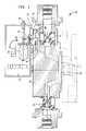
- FIG. 1is a cross-sectional view of the pump and effervescent gas bleeder apparatus of the present invention
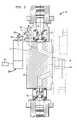
- FIG. 2is a cross-sectional view of an alternate embodiment of the effervescent gas bleeder apparatus of the present invention
- FIG. 3is a cross-sectional view of another alternate embodiment of the effervescent gas bleeder apparatus of the present invention.
- FIG. 5Ais a schematic diagram of the present invention controlled by a system responsive to gas detection sensors; and, FIG. 5B is a schematic diagram of the present invention controlled by a system responsive to flow detection devices.
- a diaphragm metering pump 10has a reciprocating diaphragm member 13 .
- the movement of the diaphragm 13changes the pressure in the pump head 16 so that the pump 10 alternates between an intake and discharge portion during each cycle.
- the pump head 16includes a product chamber 19 bounded on one side by a displaceable diaphragm 13 .
- the inlet and exit to the product chamberare provided with one-way check valves.
- the check valves shownare ball valves but other types of valves exist as known to those of ordinary skill in the art.
- the exit check valve 22closes under reduced pressure
- the inlet check valve 25opens and fluid is drawn into the product chamber 19 .
- pressureincreases on the fluid in the product chamber 19 , closing the inlet check valve 25 , opening the outlet check valve 22 and forcing fluid through the product side in a pulsed manner.
- an example of the gas bleeder apparatus of the present inventionis a solenoid-operated valve 28 that opens on a regularly timed basis controlled by a repeat cycle timer 29 .
- the valve 28can be operator controlled or controlled by other means.
- the solenoid-operated valve 28is a flapper type valve with a flapper element 30 attached to the end of a lever 31 that is seated on an inlet 35 in its closed position.
- a first end of the lever 31has a solenoid attachment point and the second end has a valve seal face.
- a sealing gasketis disposed along a midportion of the lever 31 . The gasket seals the valve body in the embodiment shown in FIG. 1 .
- valve 28Actuation of the valve 28 by the solenoid 33 causes the flapper element 30 to lift off of inlet 35 to open a passageway 40 that leads from the discharge side 42 of the pump 10 back into the pump head 16 .
- the valve 28may also be actuated by a pneumatic or hydraulic cylinder 100 operated by remote valve 103 .
- the pressure-balanced design of the lever-type flapper valve 28reduces the size of the solenoid 33 required to actuate the valve 28 and provides a fail-safe system such that the valve 28 will remain closed if the solenoid 33 fails.
- the flapper element 30is biased in the closed position by the pressure above the discharge check valve 22 .
- the pressure in the pump head 16is reduced, and as a result, the flapper element 30 is biased in the closed position.
- the flapper element 30remains biased in the closed position due to the following factors: gravity, the force developed by a spring acting upon the solenoid plunger, and the equal pressure on both sides of the flapper element 30 that results from the opening of the exit check valve 22 .
- Other types of valve elementscan also be used including, but not limited to diaphragm, spool, pintle, ball, or needle valves.
- the solenoid-operated valve 28may be set to actuate for a quarter of a second at regularly timed intervals of approximately thirty seconds. The intervals may be reduced or enlarged. If the intervals are reduced, the wear on the solenoid 33 and flapper element 30 is increased. If the intervals are increased, the gas evacuation time is increased. It has been found that intervals between fifteen and thirty seconds perform well, with the valve 28 being open for a quarter of a second.
- valve 28on timed intervals is independent of the operation of the diaphragm 13 on the pump 10 . Accordingly, when the valve 28 opens during certain times the liquid from the discharge side 42 of the pump 10 may return to the pump head 16 . At other times, the pressure inside the pump head 16 may cause liquid to pass through the passageway 40 to the discharge side 42 of the pump 10 . In alternate embodiments, the opening and closing of the valve 28 may be phased with the movement of the diaphragm 13 . Also, as illustrated in FIGS. 5A and 5B , the operation of valve 28 can be tied to a system 200 that is responsive to gas detection sensors 150 or flow detection devices 153 as will be evident to those of ordinary skill in the art.
- the diameter of the passageway 40can be increased to avoid problems with clogging. If the passageway is too small, crystallized material can clog the line.
- An over-ride control 50provides for manual control of the valve 28 either electrically or mechanically.
- the gas bleeder apparatus of the present inventionWhen the gas bleeder apparatus of the present invention is in operation, it allows some liquid from the discharge side 42 of the pump 10 to flow back into the pump 10 which displaces gas from the pump head 16 through the exit valve 22 . This prevents the pump 10 from “air binding” or losing prime.
- Compression ratiois defined herein as the pressure inside the pump head cavity with the diaphragm extended divided by the pressure in the pump head cavity with the diaphragm retracted.
- Diaphragm pumpsare typically capable of producing only relatively small pressure increases in the pump head due to the relatively small compression ratio and the compressibility of gases.
- the pump head 16When the valve 28 is open, the pump head 16 is being pressurized to an approximately equal pressure to the upstream pressure on the other side of the exit check valve 22 . By balancing this pressure and adding liquid back into the pump head 16 , the small pressure increase generated by the pump diaphragm is enough to open the exit check valve 22 .
- the gas bleeder apparatus of the present inventionrepeats the cycle until all of the gas is purged through the exit check valve 22 .
- the design of the pump head 16 to minimize the internal volumeimproves the purging of gases because it increases the compression ratio in the pump head 16 .
- passageway 40can be formed in numerous ways. As shown in FIG. 1 , the passageway 40 is formed integrally in the body of the pump head 16 . As shown in FIG. 3 , the passageway 40 could be connected through an external conduit 60 with a bleeder valve 62 positioned somewhere in the line. The external conduit 60 could be connected to the pump head 16 and the discharge side 42 by adapters 64 and 66 . Existing diaphragm pumps could be retrofitted in this manner with externally piped gas bleeder valves.
- valve 28could be arranged externally and specially rated for explosive environments.
Landscapes
- Engineering & Computer Science (AREA)
- Mechanical Engineering (AREA)
- General Engineering & Computer Science (AREA)
- Reciprocating Pumps (AREA)
- Details Of Reciprocating Pumps (AREA)
- Sampling And Sample Adjustment (AREA)
- Exhaust Gas After Treatment (AREA)
- Feeding, Discharge, Calcimining, Fusing, And Gas-Generation Devices (AREA)
- Gas Separation By Absorption (AREA)
Abstract
Description
Applicant hereby claims priority based on U.S. Provisional Application No. 60/414,183 filed Sep. 27, 2002, entitled “Effervescent Gas Bleeder Apparatus” which is incorporated herein by reference.
The present invention generally relates to liquid metering pumps for delivering controlled amounts of liquid from one vessel to another, or from a source of supply to a process stream. More particularly, it relates to a new and improved effervescent gas bleeder apparatus for use on a liquid metering pump to prevent the metering pump from “air binding” or losing prime.
Diaphragm metering pumps are known and used for transferring fluids from one place to another. Generally, diaphragm pumps include a pumping head area including a product chamber bounded on one side by a displaceable diaphragm member. The inlet and exit to the product chamber are provided with one way check valves. As the diaphragm is displaced away from the product chamber, the exit check valve closes under reduced pressure, the inlet check valve opens and fluid is drawn into the product chamber. Thereafter, as the diaphragm is displaced toward the product side, pressure increases on the fluid in the product chamber, closing the inlet check valve, opening the outlet check valve and forcing fluid in the product chamber out of the exit. In continuous operation, a diaphragm pump pumps fluid through the product side in a pulsed manner.
Diaphragm displacements may be achieved with a mechanical drive system or a hydraulic drive system. An example of a mechanical drive is a solenoid-actuated pump. In a solenoid-actuated pump, an actuator rod is secured at one end to the diaphragm and at its opposed end is connected to a solenoid actuator. The electrically or electronically-controlled solenoid is effective to cause reciprocal linear movement of the actuator and actuator rod thereby causing displacements of the diaphragm directly. As an alternative, a mechanical drive system may include a motor, gearbox, and eccentric cam for driving the actuator rod.
In a hydraulically driven diaphragm metering pump, diaphragm displacement is achieved by varying the pressure of a hydraulic fluid on the hydraulic side of the diaphragm through operation of a reciprocating piston disposed in fluid communication with a hydraulic chamber. Instead of direct mechanical attachment to the diaphragm, with this type of pump, a hydraulic fluid is pressurized on one side of the diaphragm to cause diaphragm displacements toward or away from the product chamber. This also results in a pulsed pumping of a fluid through the pump head.
A problem which may arise in diaphragm metering pumps occurs during operation if a volume of air is sucked into the intake lines so that air travels through the suction line, or after sitting idle, gas accumulates in the pump head or in the suction line below the pump. Air or gas in the intake or pump head may cause the pump to lose prime. For effervescent fluids such as Sodium Hypochlorite and Hydrogen Peroxide, the reciprocating type pumps are very susceptible to “air binding” and losing prime. If the pump loses its prime and gas fills the diaphragm metering pump head area, pumping displacements of the diaphragm may simply compress the gas and not result in any liquid pumping or fluid flow. The compressibility of gases causes this effect. If there is a loss of priming, frequently a pump cannot regain hydraulic firmness and restart pumping.
Adiaphragm metering pump 10 has a reciprocatingdiaphragm member 13. As will be evident to those of ordinary skill in the art, the movement of thediaphragm 13 changes the pressure in thepump head 16 so that thepump 10 alternates between an intake and discharge portion during each cycle.
Thepump head 16 includes aproduct chamber 19 bounded on one side by adisplaceable diaphragm 13. The inlet and exit to the product chamber are provided with one-way check valves. The check valves shown are ball valves but other types of valves exist as known to those of ordinary skill in the art. As thediaphragm 13 is displaced away from theproduct chamber 19, theexit check valve 22 closes under reduced pressure, theinlet check valve 25 opens and fluid is drawn into theproduct chamber 19. Thereafter as thediaphragm 13 is displaced toward the product side, pressure increases on the fluid in theproduct chamber 19, closing theinlet check valve 25, opening theoutlet check valve 22 and forcing fluid through the product side in a pulsed manner.
Referring toFIG. 1 , an example of the gas bleeder apparatus of the present invention is a solenoid-operatedvalve 28 that opens on a regularly timed basis controlled by arepeat cycle timer 29. As an alternative, thevalve 28 can be operator controlled or controlled by other means. The solenoid-operatedvalve 28 is a flapper type valve with aflapper element 30 attached to the end of alever 31 that is seated on aninlet 35 in its closed position. As shown inFIG. 4 , a first end of thelever 31 has a solenoid attachment point and the second end has a valve seal face. A sealing gasket is disposed along a midportion of thelever 31. The gasket seals the valve body in the embodiment shown inFIG. 1 . Actuation of thevalve 28 by thesolenoid 33 causes theflapper element 30 to lift off ofinlet 35 to open apassageway 40 that leads from thedischarge side 42 of thepump 10 back into thepump head 16. As an alternative (shown inFIG. 2 ), thevalve 28 may also be actuated by a pneumatic orhydraulic cylinder 100 operated byremote valve 103.
The pressure-balanced design of the lever-type flapper valve 28 reduces the size of thesolenoid 33 required to actuate thevalve 28 and provides a fail-safe system such that thevalve 28 will remain closed if thesolenoid 33 fails. Theflapper element 30 is biased in the closed position by the pressure above thedischarge check valve 22. On the intake cycle of thepump 10, the pressure in thepump head 16 is reduced, and as a result, theflapper element 30 is biased in the closed position. During the discharge cycle, theflapper element 30 remains biased in the closed position due to the following factors: gravity, the force developed by a spring acting upon the solenoid plunger, and the equal pressure on both sides of theflapper element 30 that results from the opening of theexit check valve 22. Other types of valve elements can also be used including, but not limited to diaphragm, spool, pintle, ball, or needle valves.
The solenoid-operatedvalve 28 may be set to actuate for a quarter of a second at regularly timed intervals of approximately thirty seconds. The intervals may be reduced or enlarged. If the intervals are reduced, the wear on thesolenoid 33 andflapper element 30 is increased. If the intervals are increased, the gas evacuation time is increased. It has been found that intervals between fifteen and thirty seconds perform well, with thevalve 28 being open for a quarter of a second.
The operation of thevalve 28 on timed intervals is independent of the operation of thediaphragm 13 on thepump 10. Accordingly, when thevalve 28 opens during certain times the liquid from thedischarge side 42 of thepump 10 may return to thepump head 16. At other times, the pressure inside thepump head 16 may cause liquid to pass through thepassageway 40 to thedischarge side 42 of thepump 10. In alternate embodiments, the opening and closing of thevalve 28 may be phased with the movement of thediaphragm 13. Also, as illustrated inFIGS. 5A and 5B , the operation ofvalve 28 can be tied to asystem 200 that is responsive togas detection sensors 150 orflow detection devices 153 as will be evident to those of ordinary skill in the art.
By providing avalve 28 that opens intermittently, the diameter of thepassageway 40 can be increased to avoid problems with clogging. If the passageway is too small, crystallized material can clog the line.
Anover-ride control 50 provides for manual control of thevalve 28 either electrically or mechanically.
When the gas bleeder apparatus of the present invention is in operation, it allows some liquid from thedischarge side 42 of thepump 10 to flow back into thepump 10 which displaces gas from thepump head 16 through theexit valve 22. This prevents thepump 10 from “air binding” or losing prime.
Compression ratio is defined herein as the pressure inside the pump head cavity with the diaphragm extended divided by the pressure in the pump head cavity with the diaphragm retracted. Diaphragm pumps are typically capable of producing only relatively small pressure increases in the pump head due to the relatively small compression ratio and the compressibility of gases.
When thevalve 28 is open, thepump head 16 is being pressurized to an approximately equal pressure to the upstream pressure on the other side of theexit check valve 22. By balancing this pressure and adding liquid back into thepump head 16, the small pressure increase generated by the pump diaphragm is enough to open theexit check valve 22.
When a gas bubble is present in thepump head 16 or in the suction line below the pump, the gas bleeder apparatus of the present invention repeats the cycle until all of the gas is purged through theexit check valve 22. The design of thepump head 16 to minimize the internal volume improves the purging of gases because it increases the compression ratio in thepump head 16.
It will be obvious to those of ordinary skill in the art thatpassageway 40 can be formed in numerous ways. As shown inFIG. 1 , thepassageway 40 is formed integrally in the body of thepump head 16. As shown inFIG. 3 , thepassageway 40 could be connected through anexternal conduit 60 with ableeder valve 62 positioned somewhere in the line. Theexternal conduit 60 could be connected to thepump head 16 and thedischarge side 42 byadapters
It is also contemplated that thevalve 28 could be arranged externally and specially rated for explosive environments.
While the invention has been described in connection with certain embodiments, it is not intended to limit the scope of the invention to the particular forms set forth, but, on the contrary, it is intended to cover such alternatives, modifications, and equivalents as may be included within the spirit and scope of the invention as defined by the appended claims.
Claims (24)
1. A diaphragm metering pump, comprising:
a pump head including a product chamber having an inlet end with a one-way inlet valve and an outlet end with a one-way outlet valve;
a displaceable diaphragm member defining a boundary of the product chamber, the diaphragm member capable of being reciprocated to cause pumping displacements;
a discharge side disposed downstream from the outlet valve;
a passageway in fluid communication between the discharge side and the product chamber;
a valve disposed in the passageway; and,
wherein the valve is a lever-type flapper valve.
2. The diaphragm metering pump ofclaim 1 , wherein the valve is actuated by a solenoid.
3. The diaphragm metering pump ofclaim 1 , wherein the valve is actuated by a pneumatic cylinder operated by a remote valve.
4. The diaphragm metering pump ofclaim 1 , wherein the valve is actuated by a hydraulic cylinder operated by a remote valve.
5. A diaphragm metering pump, comprising:
a pump head including a product chamber having an inlet end with a one-way inlet valve and an outlet end with a one-way outlet valve;
a displaceable diaphragm member defining a boundary of the product chamber, the diaphragm member capable of being reciprocated to cause pumping displacements;
a discharge side disposed downstream from the outlet valve;
a passageway in fluid communication between the discharge side and the product chamber;
a valve disposed in the passageway; and,
wherein the valve is opened such that liquid from the discharge side is conveyed into the product chamber and wherein the valve is automatically opened on an intermittent basis.
6. The diaphragm metering pump ofclaim 5 , wherein the passageway is formed integrally in the pump.
7. The diaphragm metering pump ofclaim 5 , wherein the passageway is connected between adapters in fluid communication with the discharge side and the product chamber.
8. The diaphragm metering pump ofclaim 5 , wherein opening of the valve is synchronized with movement of the diaphragm member.
9. The diaphragm metering pump ofclaim 5 , wherein opening of the valve is asynchronous with movement of the diaphragm member.
10. The diaphragm metering pump ofclaim 5 , wherein opening of the valve is controlled by a system responsive to a gas detection sensor.
11. The diaphragm metering pump ofclaim 5 , wherein opening of the valve is controlled by a system responsive to a flow detection device.
12. A diaphragm metering pump, comprising:
a pump head including a product chamber having an inlet end with a one-way inlet valve and having an outlet end with a one-way outlet valve;
a displaceable diaphragm member defining a boundary of the product chamber, the diaphragm member capable of being reciprocated to cause pumping displacements;
a discharge side disposed downstream of the outlet valve;
a passageway in fluid communication between the discharge side and the product chamber; and,
a valve disposed in the passageway, the valve being controlled such that it opens on an intermittent basis to allow liquid to re-enter the product chamber in an amount effective to purge gas from the product chamber to prevent loss of prime; and,
wherein the valve is actuated by a solenoid.
13. The diaphragm metering pump ofclaim 12 , wherein the valve is actuated by a pneumatic cylinder operated by a remote valve.
14. The diaphragm metering pump ofclaim 12 , wherein the valve is actuated by a hydraulic cylinder operated by a remote valve.
15. The diaphragm metering pump ofclaim 12 , wherein the passageway is formed integrally in the pump.
16. The diaphragm metering pump ofclaim 12 , wherein the passageway is connected between adapters in fluid communication with the discharge side and the product chamber.
17. The diaphragm metering pump ofclaim 12 , wherein the valve is a lever-type flapper valve.
18. A diaphragm metering pump, comprising:
a pump head including a product chamber having an inlet end with a one-way inlet valve and having an outlet end with a one-way outlet valve;
a displaceable diaphragm member defining a boundary of the product chamber, the diaphragm member capable of being reciprocated to cause pumping displacements;
a discharge side disposed downstream of the outlet valve;
a passageway in fluid communication between the discharge side and the product chamber; and,
a valve disposed in the passageway, the valve being controlled such that it opens on an intermittent basis to allow liquid to re-enter the product chamber in an amount effective to purge gas from the product chamber to prevent loss of prime;
wherein the valve is automatically opened on an intermittent basis.
19. The diaphragm metering pump ofclaim 18 , wherein opening of the valve is synchronized with movement of the diaphragm member.
20. The diaphragm metering pump ofclaim 18 , wherein the opening of the valve is asynchronous with movement of the diaphragm member.
21. The diaphragm metering pump ofclaim 18 , wherein the opening of the valve is controlled by a system responsive to a gas detection sensor.
22. The diaphragm metering pump ofclaim 18 , wherein the opening of the valve is controlled by a system responsive to a flow detection device.
23. The diaphragm metering pump ofclaim 18 , wherein the passageway has a smaller cross-sectional area than the product chamber.
24. A method of bleeding an effervescent gas from a diaphragm metering pump, comprising:
providing a pump head including a product chamber having an inlet end with a one-way inlet valve and an outlet end with a one-way outlet valve; a displaceable diaphragm member defining a boundary of the product chamber, the diaphragm member capable of being reciprocated to cause pumping displacements; a discharge side disposed downstream from the outlet valve; a passageway in fluid communication between the discharge side and the product chamber; and, a valve disposed in the passageway; and,
opening the valve on an intermittent basis to cause liquid to re-enter the product chamber in an amount effective to purge gas from the product chamber to prevent loss of prime.
Priority Applications (11)
| Application Number | Priority Date | Filing Date | Title |
|---|---|---|---|
| US10/410,935US7175397B2 (en) | 2002-09-27 | 2003-04-10 | Effervescent gas bleeder apparatus |
| PCT/US2003/030616WO2004029458A1 (en) | 2002-09-27 | 2003-09-26 | Metering pump with gas removal device |
| AT03798779TATE403086T1 (en) | 2002-09-27 | 2003-09-26 | DOSING PUMP WITH GAS REMOVAL DEVICE |
| CNB038231700ACN100436818C (en) | 2002-09-27 | 2003-09-26 | Metering pump with gas removal device |
| EP03798779AEP1546557B1 (en) | 2002-09-27 | 2003-09-26 | Metering pump with gas removal device |
| CA2499939ACA2499939C (en) | 2002-09-27 | 2003-09-26 | Metering pump with gas removal device |
| DK03798779TDK1546557T3 (en) | 2002-09-27 | 2003-09-26 | Diaphragm metering pump with gas removal device |
| DE60322552TDE60322552D1 (en) | 2002-09-27 | 2003-09-26 | DOSING PUMP WITH GAS REMOVAL DEVICE |
| AU2003277024AAU2003277024A1 (en) | 2002-09-27 | 2003-09-26 | Metering pump with gas removal device |
| US11/581,602US20070031271A1 (en) | 2002-09-27 | 2006-10-16 | Effervescent gas bleeder apparatus |
| US12/619,069US8322994B2 (en) | 2002-09-27 | 2009-11-16 | Effervescent gas bleeder apparatus |
Applications Claiming Priority (2)
| Application Number | Priority Date | Filing Date | Title |
|---|---|---|---|
| US41418302P | 2002-09-27 | 2002-09-27 | |
| US10/410,935US7175397B2 (en) | 2002-09-27 | 2003-04-10 | Effervescent gas bleeder apparatus |
Related Child Applications (1)
| Application Number | Title | Priority Date | Filing Date |
|---|---|---|---|
| US11/581,602DivisionUS20070031271A1 (en) | 2002-09-27 | 2006-10-16 | Effervescent gas bleeder apparatus |
Publications (2)
| Publication Number | Publication Date |
|---|---|
| US20040062662A1 US20040062662A1 (en) | 2004-04-01 |
| US7175397B2true US7175397B2 (en) | 2007-02-13 |
Family
ID=32033526
Family Applications (3)
| Application Number | Title | Priority Date | Filing Date |
|---|---|---|---|
| US10/410,935Expired - LifetimeUS7175397B2 (en) | 2002-09-27 | 2003-04-10 | Effervescent gas bleeder apparatus |
| US11/581,602AbandonedUS20070031271A1 (en) | 2002-09-27 | 2006-10-16 | Effervescent gas bleeder apparatus |
| US12/619,069Expired - LifetimeUS8322994B2 (en) | 2002-09-27 | 2009-11-16 | Effervescent gas bleeder apparatus |
Family Applications After (2)
| Application Number | Title | Priority Date | Filing Date |
|---|---|---|---|
| US11/581,602AbandonedUS20070031271A1 (en) | 2002-09-27 | 2006-10-16 | Effervescent gas bleeder apparatus |
| US12/619,069Expired - LifetimeUS8322994B2 (en) | 2002-09-27 | 2009-11-16 | Effervescent gas bleeder apparatus |
Country Status (9)
| Country | Link |
|---|---|
| US (3) | US7175397B2 (en) |
| EP (1) | EP1546557B1 (en) |
| CN (1) | CN100436818C (en) |
| AT (1) | ATE403086T1 (en) |
| AU (1) | AU2003277024A1 (en) |
| CA (1) | CA2499939C (en) |
| DE (1) | DE60322552D1 (en) |
| DK (1) | DK1546557T3 (en) |
| WO (1) | WO2004029458A1 (en) |
Cited By (29)
| Publication number | Priority date | Publication date | Assignee | Title |
|---|---|---|---|---|
| US20080131290A1 (en)* | 2006-11-30 | 2008-06-05 | Entegris, Inc. | System and method for operation of a pump |
| US20080175719A1 (en)* | 2006-04-14 | 2008-07-24 | Deka Products Limited Partnership | Fluid pumping systems, devices and methods |
| US20080216898A1 (en)* | 2007-02-27 | 2008-09-11 | Deka Products Limited Partnership | Cassette System Integrated Apparatus |
| US20080253427A1 (en)* | 2007-02-27 | 2008-10-16 | Deka Products Limited Partnership | Sensor Apparatus Systems, Devices and Methods |
| US20090008331A1 (en)* | 2007-02-27 | 2009-01-08 | Deka Products Limited Partnership | Hemodialysis systems and methods |
| US20090047143A1 (en)* | 2005-11-21 | 2009-02-19 | Entegris, Inc. | Method and system for high viscosity pump |
| US20090095679A1 (en)* | 2007-02-27 | 2009-04-16 | Deka Products Limited Partnership | Hemodialysis systems and methods |
| US20090099498A1 (en)* | 2007-10-12 | 2009-04-16 | Deka Products Limited Partnership | Systems, Devices and Methods for Cardiopulmonary Treatment and Procedures |
| US20090105629A1 (en)* | 2007-02-27 | 2009-04-23 | Deka Products Limited Partnership | Blood circuit assembly for a hemodialysis system |
| US20090101549A1 (en)* | 2007-02-27 | 2009-04-23 | Deka Products Limited Partnership | Modular assembly for a portable hemodialysis system |
| US20100056975A1 (en)* | 2008-08-27 | 2010-03-04 | Deka Products Limited Partnership | Blood line connector for a medical infusion device |
| US20100051529A1 (en)* | 2008-08-27 | 2010-03-04 | Deka Products Limited Partnership | Dialyzer cartridge mounting arrangement for a hemodialysis system |
| US20100051551A1 (en)* | 2007-02-27 | 2010-03-04 | Deka Products Limited Partnership | Reagent supply for a hemodialysis system |
| US20100192686A1 (en)* | 2007-02-27 | 2010-08-05 | Deka Products Limited Partnership | Blood treatment systems and methods |
| US20110098635A1 (en)* | 2008-01-23 | 2011-04-28 | Deka Research & Development | Fluid flow occluder and methods of use for medical treatment systems |
| US20110105877A1 (en)* | 2009-10-30 | 2011-05-05 | Deka Products Limited Partnership | Apparatus and method for detecting disconnection of an intravascular access device |
| US8273049B2 (en) | 2007-02-27 | 2012-09-25 | Deka Products Limited Partnership | Pumping cassette |
| US20120312399A1 (en)* | 2010-02-18 | 2012-12-13 | Grundfos Management A/S | Dosing pump |
| US8393690B2 (en) | 2007-02-27 | 2013-03-12 | Deka Products Limited Partnership | Enclosure for a portable hemodialysis system |
| US8651823B2 (en) | 2005-11-21 | 2014-02-18 | Entegris, Inc. | System and method for a pump with reduced form factor |
| US8662859B2 (en) | 2005-12-02 | 2014-03-04 | Entegris, Inc. | System and method for monitoring operation of a pump |
| US8678775B2 (en) | 2005-12-02 | 2014-03-25 | Entegris, Inc. | System and method for position control of a mechanical piston in a pump |
| US8814536B2 (en) | 2004-11-23 | 2014-08-26 | Entegris, Inc. | System and method for a variable home position dispense system |
| US8870548B2 (en) | 2005-12-02 | 2014-10-28 | Entegris, Inc. | System and method for pressure compensation in a pump |
| US9517295B2 (en) | 2007-02-27 | 2016-12-13 | Deka Products Limited Partnership | Blood treatment systems and methods |
| US9597442B2 (en) | 2007-02-27 | 2017-03-21 | Deka Products Limited Partnership | Air trap for a medical infusion device |
| US9724458B2 (en) | 2011-05-24 | 2017-08-08 | Deka Products Limited Partnership | Hemodialysis system |
| US10537671B2 (en) | 2006-04-14 | 2020-01-21 | Deka Products Limited Partnership | Automated control mechanisms in a hemodialysis apparatus |
| US11833281B2 (en) | 2008-01-23 | 2023-12-05 | Deka Products Limited Partnership | Pump cassette and methods for use in medical treatment system using a plurality of fluid lines |
Families Citing this family (18)
| Publication number | Priority date | Publication date | Assignee | Title |
|---|---|---|---|---|
| US8158102B2 (en)* | 2003-10-30 | 2012-04-17 | Deka Products Limited Partnership | System, device, and method for mixing a substance with a liquid |
| JP4723218B2 (en)* | 2004-09-10 | 2011-07-13 | シーケーディ株式会社 | Chemical liquid supply pump unit |
| US20070065305A1 (en)* | 2005-09-16 | 2007-03-22 | Almatec Maschinenbau Gmbh | Diaphragm pump for the transport of liquids |
| US20090016901A1 (en)* | 2007-07-11 | 2009-01-15 | Morris Iii Harry E | Self-priming electronic metering pump and priming methodology |
| EP2154371B1 (en)* | 2008-08-14 | 2018-09-19 | Bran + Lübbe GmbH | Pumping device |
| EP2362102B1 (en)* | 2010-02-18 | 2012-10-03 | Grundfos Management A/S | Metering pump aggregate |
| JP4977791B1 (en) | 2011-07-01 | 2012-07-18 | 株式会社タクミナ | Pump and pump operation method |
| CN103703251B (en)* | 2011-08-25 | 2016-12-21 | 艺康股份有限公司 | Self-venting diaphragm pump for metering fluids and corresponding method |
| DE102012102088A1 (en) | 2012-03-13 | 2013-09-19 | Prominent Dosiertechnik Gmbh | Positive displacement pump with forced ventilation |
| DE102012106848A1 (en)* | 2012-07-27 | 2014-01-30 | Prominent Dosiertechnik Gmbh | Dosing system and metering pump for this |
| US20140056724A1 (en)* | 2012-08-27 | 2014-02-27 | Hamilton Sundstrand Corporation | Diaphragm metering pump having a degassing system |
| FR3012538B1 (en)* | 2013-10-30 | 2018-05-18 | Dosatron International | MEMBRANE PUMP AND VALVE DEVICE FOR SUCH A PUMP |
| FR3021713B1 (en)* | 2014-05-27 | 2019-04-05 | Milton Roy Europe | HYDRAULICALLY CONTROLLED MEMBRANE PUMP COMPRISING A DEDICATED DEGASSAGE PATH |
| CN104196711A (en)* | 2014-08-31 | 2014-12-10 | 杭州天健流体控制设备有限公司 | Device for solving problem that metering pump cannot be used normally due to fact that liquid contains gas or is prone to generating gas |
| DE102014112833A1 (en)* | 2014-09-05 | 2016-03-10 | Prominent Gmbh | Positive displacement pump with fluid reservoir |
| US10066612B2 (en) | 2015-07-01 | 2018-09-04 | Caterpillar Inc. | Method of operating cryogenic pump and cryogenic pump system |
| DE102019105191A1 (en)* | 2019-02-28 | 2020-09-03 | Prominent Gmbh | Positive displacement pump with surfaces that promote flow |
| DE102020119502A1 (en) | 2020-07-23 | 2022-01-27 | Washtec Holding Gmbh | METHOD OF OPERATING A DOSING PUMP IN A LIQUID SUPPLY SYSTEM |
Citations (12)
| Publication number | Priority date | Publication date | Assignee | Title |
|---|---|---|---|---|
| US2978149A (en)* | 1959-12-18 | 1961-04-04 | Rosen Sidney | Variable pressure suck-back device for a pump |
| US3623661A (en) | 1969-02-28 | 1971-11-30 | Josef Wagner | Feed arrangement for spray painting |
| US4184809A (en) | 1977-05-11 | 1980-01-22 | Louis Beck | Diaphragm pump construction having pulsator piston and mechanically actuated means to supply pulsator fluid |
| US4378201A (en) | 1980-11-19 | 1983-03-29 | Graco Inc. | Diaphragm pump having spool and guide members |
| US4599049A (en) | 1982-01-11 | 1986-07-08 | Hewlett-Packard Company | High pressure meter pump |
| US4722230A (en) | 1986-05-29 | 1988-02-02 | Graco Inc. | Pressure gauge for high pressure flow through diaphragm pump |
| EP0427988A1 (en) | 1989-11-14 | 1991-05-22 | Fraunhofer-Gesellschaft Zur Förderung Der Angewandten Forschung E.V. | Membrane pump |
| US5186615A (en) | 1990-06-26 | 1993-02-16 | Karldom Corporation | Diaphragm pump |
| US5205722A (en) | 1991-06-04 | 1993-04-27 | Hammond John M | Metering pump |
| US5647733A (en) | 1995-12-01 | 1997-07-15 | Pulsafeeder Inc. | Diaphragm metering pump having modular construction |
| US6086340A (en)* | 1999-05-11 | 2000-07-11 | Milton Roy Company | Metering diaphragm pump having a front removable hydraulic refill valve |
| US6345962B1 (en) | 2000-05-22 | 2002-02-12 | Douglas E. Sutter | Fluid operated pump |
Family Cites Families (3)
| Publication number | Priority date | Publication date | Assignee | Title |
|---|---|---|---|---|
| US2997093A (en)* | 1958-01-10 | 1961-08-22 | Keelavite Co Ltd | Pumps |
| DE19848217B4 (en)* | 1998-10-20 | 2013-06-27 | Wabco Gmbh | gas compressor |
| CN2466377Y (en)* | 2001-02-15 | 2001-12-19 | 常州市江南电力设备厂 | Diaphragm metering pump |
- 2003
- 2003-04-10USUS10/410,935patent/US7175397B2/ennot_activeExpired - Lifetime
- 2003-09-26DKDK03798779Tpatent/DK1546557T3/enactive
- 2003-09-26EPEP03798779Apatent/EP1546557B1/ennot_activeExpired - Lifetime
- 2003-09-26AUAU2003277024Apatent/AU2003277024A1/ennot_activeAbandoned
- 2003-09-26CACA2499939Apatent/CA2499939C/ennot_activeExpired - Lifetime
- 2003-09-26CNCNB038231700Apatent/CN100436818C/ennot_activeExpired - Fee Related
- 2003-09-26DEDE60322552Tpatent/DE60322552D1/ennot_activeExpired - Lifetime
- 2003-09-26WOPCT/US2003/030616patent/WO2004029458A1/ennot_activeApplication Discontinuation
- 2003-09-26ATAT03798779Tpatent/ATE403086T1/ennot_activeIP Right Cessation
- 2006
- 2006-10-16USUS11/581,602patent/US20070031271A1/ennot_activeAbandoned
- 2009
- 2009-11-16USUS12/619,069patent/US8322994B2/ennot_activeExpired - Lifetime
Patent Citations (14)
| Publication number | Priority date | Publication date | Assignee | Title |
|---|---|---|---|---|
| US2978149A (en)* | 1959-12-18 | 1961-04-04 | Rosen Sidney | Variable pressure suck-back device for a pump |
| US3623661A (en) | 1969-02-28 | 1971-11-30 | Josef Wagner | Feed arrangement for spray painting |
| US4184809A (en) | 1977-05-11 | 1980-01-22 | Louis Beck | Diaphragm pump construction having pulsator piston and mechanically actuated means to supply pulsator fluid |
| US4378201A (en) | 1980-11-19 | 1983-03-29 | Graco Inc. | Diaphragm pump having spool and guide members |
| US4599049A (en) | 1982-01-11 | 1986-07-08 | Hewlett-Packard Company | High pressure meter pump |
| US4722230A (en) | 1986-05-29 | 1988-02-02 | Graco Inc. | Pressure gauge for high pressure flow through diaphragm pump |
| EP0427988A1 (en) | 1989-11-14 | 1991-05-22 | Fraunhofer-Gesellschaft Zur Förderung Der Angewandten Forschung E.V. | Membrane pump |
| US5186615A (en) | 1990-06-26 | 1993-02-16 | Karldom Corporation | Diaphragm pump |
| US5205722A (en) | 1991-06-04 | 1993-04-27 | Hammond John M | Metering pump |
| US5647733A (en) | 1995-12-01 | 1997-07-15 | Pulsafeeder Inc. | Diaphragm metering pump having modular construction |
| US5667368A (en) | 1995-12-01 | 1997-09-16 | Pulsafeeder, Inc. | Diaphragm metering pump including improved leak detection diaphragm |
| US5860793A (en) | 1995-12-01 | 1999-01-19 | Pulsafeeder, Inc. | Diaphragm metering pump with push to prime air bleeder valve |
| US6086340A (en)* | 1999-05-11 | 2000-07-11 | Milton Roy Company | Metering diaphragm pump having a front removable hydraulic refill valve |
| US6345962B1 (en) | 2000-05-22 | 2002-02-12 | Douglas E. Sutter | Fluid operated pump |
Cited By (81)
| Publication number | Priority date | Publication date | Assignee | Title |
|---|---|---|---|---|
| US8814536B2 (en) | 2004-11-23 | 2014-08-26 | Entegris, Inc. | System and method for a variable home position dispense system |
| US9617988B2 (en) | 2004-11-23 | 2017-04-11 | Entegris, Inc. | System and method for variable dispense position |
| US9399989B2 (en) | 2005-11-21 | 2016-07-26 | Entegris, Inc. | System and method for a pump with onboard electronics |
| US8651823B2 (en) | 2005-11-21 | 2014-02-18 | Entegris, Inc. | System and method for a pump with reduced form factor |
| US8753097B2 (en) | 2005-11-21 | 2014-06-17 | Entegris, Inc. | Method and system for high viscosity pump |
| US20090047143A1 (en)* | 2005-11-21 | 2009-02-19 | Entegris, Inc. | Method and system for high viscosity pump |
| US9816502B2 (en) | 2005-12-02 | 2017-11-14 | Entegris, Inc. | System and method for pressure compensation in a pump |
| US9309872B2 (en) | 2005-12-02 | 2016-04-12 | Entegris, Inc. | System and method for position control of a mechanical piston in a pump |
| US8870548B2 (en) | 2005-12-02 | 2014-10-28 | Entegris, Inc. | System and method for pressure compensation in a pump |
| US8678775B2 (en) | 2005-12-02 | 2014-03-25 | Entegris, Inc. | System and method for position control of a mechanical piston in a pump |
| US8662859B2 (en) | 2005-12-02 | 2014-03-04 | Entegris, Inc. | System and method for monitoring operation of a pump |
| US8870549B2 (en) | 2006-04-14 | 2014-10-28 | Deka Products Limited Partnership | Fluid pumping systems, devices and methods |
| US8292594B2 (en) | 2006-04-14 | 2012-10-23 | Deka Products Limited Partnership | Fluid pumping systems, devices and methods |
| US10537671B2 (en) | 2006-04-14 | 2020-01-21 | Deka Products Limited Partnership | Automated control mechanisms in a hemodialysis apparatus |
| US20080175719A1 (en)* | 2006-04-14 | 2008-07-24 | Deka Products Limited Partnership | Fluid pumping systems, devices and methods |
| US9631611B2 (en) | 2006-11-30 | 2017-04-25 | Entegris, Inc. | System and method for operation of a pump |
| US20080131290A1 (en)* | 2006-11-30 | 2008-06-05 | Entegris, Inc. | System and method for operation of a pump |
| US9115708B2 (en) | 2007-02-27 | 2015-08-25 | Deka Products Limited Partnership | Fluid balancing systems and methods |
| US9272082B2 (en) | 2007-02-27 | 2016-03-01 | Deka Products Limited Partnership | Pumping cassette |
| US8273049B2 (en) | 2007-02-27 | 2012-09-25 | Deka Products Limited Partnership | Pumping cassette |
| US12059516B2 (en) | 2007-02-27 | 2024-08-13 | Deka Products Limited Partnership | Blood circuit assembly for a hemodialysis system |
| US8317492B2 (en) | 2007-02-27 | 2012-11-27 | Deka Products Limited Partnership | Pumping cassette |
| US11793915B2 (en) | 2007-02-27 | 2023-10-24 | Deka Products Limited Partnership | Hemodialysis systems and methods |
| US8357298B2 (en) | 2007-02-27 | 2013-01-22 | Deka Products Limited Partnership | Hemodialysis systems and methods |
| US8393690B2 (en) | 2007-02-27 | 2013-03-12 | Deka Products Limited Partnership | Enclosure for a portable hemodialysis system |
| US8409441B2 (en) | 2007-02-27 | 2013-04-02 | Deka Products Limited Partnership | Blood treatment systems and methods |
| US8425471B2 (en) | 2007-02-27 | 2013-04-23 | Deka Products Limited Partnership | Reagent supply for a hemodialysis system |
| US8459292B2 (en) | 2007-02-27 | 2013-06-11 | Deka Products Limited Partnership | Cassette system integrated apparatus |
| US8491184B2 (en) | 2007-02-27 | 2013-07-23 | Deka Products Limited Partnership | Sensor apparatus systems, devices and methods |
| US8499780B2 (en) | 2007-02-27 | 2013-08-06 | Deka Products Limited Partnership | Cassette system integrated apparatus |
| US8545698B2 (en) | 2007-02-27 | 2013-10-01 | Deka Products Limited Partnership | Hemodialysis systems and methods |
| US8562834B2 (en) | 2007-02-27 | 2013-10-22 | Deka Products Limited Partnership | Modular assembly for a portable hemodialysis system |
| US11752244B2 (en) | 2007-02-27 | 2023-09-12 | Deka Products Limited Partnership | Blood circuit assembly for a hemodialysis system |
| US20100192686A1 (en)* | 2007-02-27 | 2010-08-05 | Deka Products Limited Partnership | Blood treatment systems and methods |
| US20100051551A1 (en)* | 2007-02-27 | 2010-03-04 | Deka Products Limited Partnership | Reagent supply for a hemodialysis system |
| US8721884B2 (en) | 2007-02-27 | 2014-05-13 | Deka Products Limited Partnership | Hemodialysis systems and methods |
| US8721879B2 (en) | 2007-02-27 | 2014-05-13 | Deka Products Limited Partnership | Hemodialysis systems and methods |
| US10851769B2 (en) | 2007-02-27 | 2020-12-01 | Deka Products Limited Partnership | Pumping cassette |
| US20080216898A1 (en)* | 2007-02-27 | 2008-09-11 | Deka Products Limited Partnership | Cassette System Integrated Apparatus |
| US10500327B2 (en) | 2007-02-27 | 2019-12-10 | Deka Products Limited Partnership | Blood circuit assembly for a hemodialysis system |
| US20090101549A1 (en)* | 2007-02-27 | 2009-04-23 | Deka Products Limited Partnership | Modular assembly for a portable hemodialysis system |
| US20090105629A1 (en)* | 2007-02-27 | 2009-04-23 | Deka Products Limited Partnership | Blood circuit assembly for a hemodialysis system |
| US8888470B2 (en) | 2007-02-27 | 2014-11-18 | Deka Products Limited Partnership | Pumping cassette |
| US8926294B2 (en) | 2007-02-27 | 2015-01-06 | Deka Products Limited Partnership | Pumping cassette |
| US8985133B2 (en) | 2007-02-27 | 2015-03-24 | Deka Products Limited Partnership | Cassette system integrated apparatus |
| US8992189B2 (en) | 2007-02-27 | 2015-03-31 | Deka Products Limited Partnership | Cassette system integrated apparatus |
| US8992075B2 (en) | 2007-02-27 | 2015-03-31 | Deka Products Limited Partnership | Sensor apparatus systems, devices and methods |
| US8246826B2 (en) | 2007-02-27 | 2012-08-21 | Deka Products Limited Partnership | Hemodialysis systems and methods |
| US10441697B2 (en) | 2007-02-27 | 2019-10-15 | Deka Products Limited Partnership | Modular assembly for a portable hemodialysis system |
| US9555179B2 (en) | 2007-02-27 | 2017-01-31 | Deka Products Limited Partnership | Hemodialysis systems and methods |
| US9028691B2 (en) | 2007-02-27 | 2015-05-12 | Deka Products Limited Partnership | Blood circuit assembly for a hemodialysis system |
| US9302037B2 (en) | 2007-02-27 | 2016-04-05 | Deka Products Limited Partnership | Hemodialysis systems and methods |
| US10077766B2 (en) | 2007-02-27 | 2018-09-18 | Deka Products Limited Partnership | Pumping cassette |
| US20090095679A1 (en)* | 2007-02-27 | 2009-04-16 | Deka Products Limited Partnership | Hemodialysis systems and methods |
| US9517295B2 (en) | 2007-02-27 | 2016-12-13 | Deka Products Limited Partnership | Blood treatment systems and methods |
| US9535021B2 (en) | 2007-02-27 | 2017-01-03 | Deka Products Limited Partnership | Sensor apparatus systems, devices and methods |
| US9539379B2 (en) | 2007-02-27 | 2017-01-10 | Deka Products Limited Partnership | Enclosure for a portable hemodialysis system |
| US8042563B2 (en) | 2007-02-27 | 2011-10-25 | Deka Products Limited Partnership | Cassette system integrated apparatus |
| US9597442B2 (en) | 2007-02-27 | 2017-03-21 | Deka Products Limited Partnership | Air trap for a medical infusion device |
| US9603985B2 (en) | 2007-02-27 | 2017-03-28 | Deka Products Limited Partnership | Blood treatment systems and methods |
| US20090008331A1 (en)* | 2007-02-27 | 2009-01-08 | Deka Products Limited Partnership | Hemodialysis systems and methods |
| US9987407B2 (en) | 2007-02-27 | 2018-06-05 | Deka Products Limited Partnership | Blood circuit assembly for a hemodialysis system |
| US9649418B2 (en) | 2007-02-27 | 2017-05-16 | Deka Products Limited Partnership | Pumping cassette |
| US9677554B2 (en) | 2007-02-27 | 2017-06-13 | Deka Products Limited Partnership | Cassette system integrated apparatus |
| US9700660B2 (en) | 2007-02-27 | 2017-07-11 | Deka Products Limited Partnership | Pumping cassette |
| US9951768B2 (en) | 2007-02-27 | 2018-04-24 | Deka Products Limited Partnership | Cassette system integrated apparatus |
| US20080253427A1 (en)* | 2007-02-27 | 2008-10-16 | Deka Products Limited Partnership | Sensor Apparatus Systems, Devices and Methods |
| US8105265B2 (en) | 2007-10-12 | 2012-01-31 | Deka Products Limited Partnership | Systems, devices and methods for cardiopulmonary treatment and procedures |
| US20090099498A1 (en)* | 2007-10-12 | 2009-04-16 | Deka Products Limited Partnership | Systems, Devices and Methods for Cardiopulmonary Treatment and Procedures |
| US9028440B2 (en) | 2008-01-23 | 2015-05-12 | Deka Products Limited Partnership | Fluid flow occluder and methods of use for medical treatment systems |
| US11833281B2 (en) | 2008-01-23 | 2023-12-05 | Deka Products Limited Partnership | Pump cassette and methods for use in medical treatment system using a plurality of fluid lines |
| US20110098635A1 (en)* | 2008-01-23 | 2011-04-28 | Deka Research & Development | Fluid flow occluder and methods of use for medical treatment systems |
| US9839776B2 (en) | 2008-01-23 | 2017-12-12 | Deka Products Limited Partnership | Fluid flow occluder and methods of use for medical treatment systems |
| US20100051529A1 (en)* | 2008-08-27 | 2010-03-04 | Deka Products Limited Partnership | Dialyzer cartridge mounting arrangement for a hemodialysis system |
| US8771508B2 (en) | 2008-08-27 | 2014-07-08 | Deka Products Limited Partnership | Dialyzer cartridge mounting arrangement for a hemodialysis system |
| US20100056975A1 (en)* | 2008-08-27 | 2010-03-04 | Deka Products Limited Partnership | Blood line connector for a medical infusion device |
| US10201650B2 (en) | 2009-10-30 | 2019-02-12 | Deka Products Limited Partnership | Apparatus and method for detecting disconnection of an intravascular access device |
| US20110105877A1 (en)* | 2009-10-30 | 2011-05-05 | Deka Products Limited Partnership | Apparatus and method for detecting disconnection of an intravascular access device |
| US20120312399A1 (en)* | 2010-02-18 | 2012-12-13 | Grundfos Management A/S | Dosing pump |
| US10780213B2 (en) | 2011-05-24 | 2020-09-22 | Deka Products Limited Partnership | Hemodialysis system |
| US9724458B2 (en) | 2011-05-24 | 2017-08-08 | Deka Products Limited Partnership | Hemodialysis system |
Also Published As
| Publication number | Publication date |
|---|---|
| US20070031271A1 (en) | 2007-02-08 |
| WO2004029458A1 (en) | 2004-04-08 |
| US20100232995A1 (en) | 2010-09-16 |
| CN1685156A (en) | 2005-10-19 |
| CA2499939C (en) | 2011-08-23 |
| DK1546557T3 (en) | 2008-12-01 |
| EP1546557B1 (en) | 2008-07-30 |
| EP1546557A1 (en) | 2005-06-29 |
| US8322994B2 (en) | 2012-12-04 |
| CN100436818C (en) | 2008-11-26 |
| ATE403086T1 (en) | 2008-08-15 |
| DE60322552D1 (en) | 2008-09-11 |
| CA2499939A1 (en) | 2004-04-08 |
| AU2003277024A1 (en) | 2004-04-19 |
| US20040062662A1 (en) | 2004-04-01 |
Similar Documents
| Publication | Publication Date | Title |
|---|---|---|
| US7175397B2 (en) | Effervescent gas bleeder apparatus | |
| US8430081B2 (en) | Direct-injection system fuel pump with a maximum-pressure valve | |
| US4303376A (en) | Flow metering cassette and controller | |
| JP4701227B2 (en) | Plunger high pressure fuel pump | |
| EP0711905B1 (en) | Improved mechanical shift, pneumatic assist pilot valve | |
| CN103597198B (en) | Inlet valve settings for fuel pumps | |
| EP1898085A3 (en) | An electromagnetic drive mechanism of a high-pressure fuel supply pump | |
| CN101743403A (en) | Diaphragm pump position control with offset valve axis | |
| JPH02140470A (en) | Fixed quantity pump | |
| US10094346B1 (en) | Fuel pump with an improved maximum-pressure valve for a direct-injection system | |
| JP4551399B2 (en) | Common rail fuel supply system | |
| US5551847A (en) | Lost motion pilot valve for diaphragm pump | |
| EP2888477B1 (en) | Diaphragm metering pump having a degassing system | |
| US6530556B1 (en) | Control unit for controlling a pressure build-up in a pump unit | |
| US5934886A (en) | Metering pump with piston and diaphragms | |
| KR100912772B1 (en) | Air boost pump | |
| JP5178618B2 (en) | High pressure fuel supply pump | |
| KR100641819B1 (en) | Piston pump | |
| JP2004339948A (en) | Pulsating pump | |
| WO1997018397A1 (en) | Slow start supply and exhaust valve | |
| JP7397729B2 (en) | Fuel pump | |
| JP2011021652A (en) | Liquid drip preventing check valve | |
| JPS591352B2 (en) | Chiyuuniyu pump | |
| JP3945226B2 (en) | High pressure fuel pump | |
| JPH05288133A (en) | Flow rate controller of volume type pump |
Legal Events
| Date | Code | Title | Description |
|---|---|---|---|
| AS | Assignment | Owner name:PULSAFEEDER, INC., NEW YORK Free format text:ASSIGNMENT OF ASSIGNORS INTEREST;ASSIGNORS:CLAUDE, CORDELL E.;MUSCARELLA, STEPHEN B.;MILLER, PATRICK F.;REEL/FRAME:013966/0770 Effective date:20030403 | |
| STCF | Information on status: patent grant | Free format text:PATENTED CASE | |
| FPAY | Fee payment | Year of fee payment:4 | |
| REMI | Maintenance fee reminder mailed | ||
| FEPP | Fee payment procedure | Free format text:PAYOR NUMBER ASSIGNED (ORIGINAL EVENT CODE: ASPN); ENTITY STATUS OF PATENT OWNER: LARGE ENTITY | |
| FPAY | Fee payment | Year of fee payment:8 | |
| SULP | Surcharge for late payment | Year of fee payment:7 | |
| MAFP | Maintenance fee payment | Free format text:PAYMENT OF MAINTENANCE FEE, 12TH YEAR, LARGE ENTITY (ORIGINAL EVENT CODE: M1553) Year of fee payment:12 |