US7174561B2 - MPEG dual-channel decoder data and control protocols for real-time video streaming - Google Patents
MPEG dual-channel decoder data and control protocols for real-time video streamingDownload PDFInfo
- Publication number
- US7174561B2 US7174561B2US09/834,427US83442701AUS7174561B2US 7174561 B2US7174561 B2US 7174561B2US 83442701 AUS83442701 AUS 83442701AUS 7174561 B2US7174561 B2US 7174561B2
- Authority
- US
- United States
- Prior art keywords
- decoder
- video
- mpeg
- data
- decoders
- Prior art date
- Legal status (The legal status is an assumption and is not a legal conclusion. Google has not performed a legal analysis and makes no representation as to the accuracy of the status listed.)
- Expired - Lifetime, expires
Links
Images


Classifications
- H—ELECTRICITY
- H04—ELECTRIC COMMUNICATION TECHNIQUE
- H04N—PICTORIAL COMMUNICATION, e.g. TELEVISION
- H04N21/00—Selective content distribution, e.g. interactive television or video on demand [VOD]
- H04N21/20—Servers specifically adapted for the distribution of content, e.g. VOD servers; Operations thereof
- H04N21/23—Processing of content or additional data; Elementary server operations; Server middleware
- H04N21/234—Processing of video elementary streams, e.g. splicing of video streams or manipulating encoded video stream scene graphs
- H04N21/23424—Processing of video elementary streams, e.g. splicing of video streams or manipulating encoded video stream scene graphs involving splicing one content stream with another content stream, e.g. for inserting or substituting an advertisement
- H—ELECTRICITY
- H04—ELECTRIC COMMUNICATION TECHNIQUE
- H04N—PICTORIAL COMMUNICATION, e.g. TELEVISION
- H04N21/00—Selective content distribution, e.g. interactive television or video on demand [VOD]
- H04N21/40—Client devices specifically adapted for the reception of or interaction with content, e.g. set-top-box [STB]; Operations thereof
- H04N21/43—Processing of content or additional data, e.g. demultiplexing additional data from a digital video stream; Elementary client operations, e.g. monitoring of home network or synchronising decoder's clock; Client middleware
- H04N21/44—Processing of video elementary streams, e.g. splicing a video clip retrieved from local storage with an incoming video stream or rendering scenes according to encoded video stream scene graphs
- H04N21/44016—Processing of video elementary streams, e.g. splicing a video clip retrieved from local storage with an incoming video stream or rendering scenes according to encoded video stream scene graphs involving splicing one content stream with another content stream, e.g. for substituting a video clip
Definitions
- the present inventionrelates to storage and processing of compressed visual data, and in particular the decoding of MPEG data for real-time splicing and streaming of video from storage in a video server.
- MPEGis an acronym for the Moving Picture Experts Group, which was set up by the International Standards Organization (ISO) to work on compression.
- ISOInternational Standards Organization
- MPEGprovides a number of different variations (MPEG-1, MPEG-2, etc.) to suit different bandwidth and quality constraints.
- MPEG-2for example, is especially suited to the storage and transmission of broadcast quality television programs.
- MPEGprovides a high degree of compression (up to 200:1) by encoding 8 ⁇ 8 blocks of pixels into a set of discrete cosine transform (DCT) coefficients, quantizing and encoding the coefficients, and using motion compensation techniques to encode most video frames as predictions from or between other frames.
- the encoded MPEG video streamis comprised of a series of groups of pictures (GOPs), and each GOP begins with an independently encoded (intra) I frame and may include one or more following P-frames and B-frames. Each I frame can be decoded without information from any preceding and/or following frame. Decoding of a P frame requires information from a preceding frame in the GOP.
- Decoding of a B framerequires information from a preceding and following frame in the GOP.
- each B frameis transmitted in reverse of its presentation order, so that all the information of the other frames required for decoding the B frame will arrive at the decoder before the B frame.
- the MPEG standardprovides a generic framework for combining one or more elementary streams of digital video and audio, as well as system data, into single or multiple program transport streams (TS) which are suitable for storage or transmission.
- the system dataincludes information about synchronization, random access, management of buffers to prevent overflow and underflow, and time stamps for video frames and audio packetized elementary stream packets.
- the standardspecifies the organization of the elementary streams and the transport streams, and imposes constraints to enable synchronized decoding from the audio and video decoding buffers under various conditions.
- the MPEG-2 standardis documented in ISO/IEC International Standard (IS) 13818-1, “Information Technology-Generic Coding of Moving Pictures and Associated Audio Information: Systems,” ISO/IEC IS 13818-2, “Information Technology-Generic Coding of Moving Pictures and Associated Information: Video,” and ISO/IEC IS 13818-3, “Information Technology-Generic Coding of Moving Pictures and Associated Audio Information: Audio,” incorporated herein by reference.
- ISO/IEC International Standard (IS) 13818-1“Information Technology-Generic Coding of Moving Pictures and Associated Audio Information: Systems”
- ISO/IEC IS 13818-2“Information Technology-Generic Coding of Moving Pictures and Associated Information: Video”
- ISO/IEC IS 13818-3“Information Technology-Generic Coding of Moving Pictures and Associated Audio Information: Audio,” incorporated herein by reference.
- a concise introduction to MPEGis given in “A guide to MPEG Fundamentals and Protocol Analysis (Including DVB and ATSC),” Tektronix Inc
- Splicing of audio/visual programsis a common operation performed, for example, whenever one encoded television program is switched to another. Splicing may be done for commercial insertion, studio routing, camera switching, and program editing.
- the splicing of MPEG encoded audio/visual streamsis considerably more difficult than splicing of the uncompressed audio and video.
- the P and B framescannot be decoded without a preceding I frame, so that cutting into a stream after an I frame renders the P and B frames meaningless.
- the P and B framesare considerably smaller than the I frames, so that the frame boundaries are not evenly spaced and must be dynamically synchronized between the two streams at the time of the splice.
- a video decoder bufferis required to compensate for the uneven spacing of the frame boundaries in the encoded streams, splicing may cause underflow or overflow of the video decoder buffer.
- Appendix Kentitled “Splicing Transport Streams,” to the MPEG-2 standard ISO/IEC 13818-1 1996.
- Appendix Krecognizes that a splice can be “seamless” when it does not result in a decoding discontinuity, or a splice can be “non-seamless” when it results in a decoding discontinuity. In either case, however, it is possible that the spliced stream will cause buffer overflow.
- SMPTESociety of Motion Picture and Television Engineers
- SMPTEThe Society of Motion Picture and Television Engineers (SMPTE) apparently thought that the ISO MPEG-2 standard was inadequate with respect to splicing. They promulgated their own SMPTE Standard 312M, entitled “Splice Points for MPEG-2 Transport Streams,” incorporated herein by reference.
- the SMPTE standarddefines constraints on the encoding of and syntax for MPEG-2 transport streams such that they may be spliced without modifying the packetized elementary stream (PES) packet payload.
- PESpacketized elementary stream
- the SMPTE standardincludes some constraints applicable to both seamless and non-seamless splicing, and other constraints that are applicable only to seamless splicing.
- a spliceoccurs from an Out-point on a first stream to an In-point on a second stream.
- the Out-pointis immediately after an I frame or P frame (in presentation order).
- the In-pointis just before a sequence header and I frame in a “closed” GOP (i.e., no prediction is allowed back before the In-point).
- frame accuracyis an important consideration whenever audio or digital video streams are spliced. If frame accuracy is not ensured, then desired frames will be missing from the spliced video stream, and undesired frames will appear in the spliced video stream. If frame inaccuracy accumulates, there could be serious schedule problems.
- the loss or addition of one or more framesis especially troublesome when commercials are inserted into program streams. Each commercial is a very short clip and the loss or addition of just a few frames can have a noticeable effect on the content of the commercial. More importantly, the loss or addition of just a few frames may result in a substantial loss of income from advertisers, because advertisers are charged a high price for each second of on-air commercial time.
- VITCvertical interval time code
- LTCLongitudinal Time Code
- Splicing operationscan be triggered upon the occurrence of a specified VITC or DVITC value in an analog or digital video stream or from LTC input.
- Video streamsare often encoded in the MPEG-2 format for storage in a video server.
- the serverstreams in real time an MPEG-2 Transport Stream (TS) with long GOP structures generally to a professional grade MPEG-2 decoder.
- the decoderdecodes the compressed MPEG-2 TS to video and audio in sequence as defined by the presentation time stamps (PTS) and display time stamps (DTS) in the video elementary streams and presentation time stamps (PTS) in the audio elementary streams.
- PTSpresentation time stamps
- DTSdisplay time stamps
- PTSpresentation time stamps
- the decoderreceives compressed data it must decode the compressed data conforming to the MPEG-2 standard starting with an I frame and ending on the last frame of the last GOP. But this decoding process is not necessarily frame accurate. To achieve frame accuracy, the decoder must be able to start on any frame other than the I frame.
- a method of producing a real-time video stream from stored MPEG encoded video clipsThe MPEG encoded video clips are contained in data storage of a video server.
- the methodincludes reading segments of the MPEG encoded video clips from the data storage.
- the segments of the MPEG encoded video clipsare decoded by respective first and second decoders in a decoder pair.
- the first decoderdecodes at least a portion of a first MPEG encoded video clip
- the second decoderdecodes at least a portion of a second MPEG encoded video clip.
- the real-time video streamis obtained by operating a video switch to switch between a video output of the first decoder and a video output of the second decoder to select a specified In-point frame in the second MPEG encoded video clip that is selectable as any MPEG frame type at any location in an MPEG group of pictures (GOP) structure.
- a video switchto switch between a video output of the first decoder and a video output of the second decoder to select a specified In-point frame in the second MPEG encoded video clip that is selectable as any MPEG frame type at any location in an MPEG group of pictures (GOP) structure.
- GOPMPEG group of pictures
- the inventionprovides a method of producing a real-time video stream from stored MPEG-2 encoded video clips.
- the MPEG-2 encoded video clipsare contained in data storage of a video file server. Segments of the MPEG-2 encoded video clips are decoded by respective first and second decoders in a decoder pair.
- the first decoderdecodes at least a portion of a first MPEG-2 encoded video clip
- the second decoderdecodes at least a portion of a second MPEG-2 encoded video clip.
- the real-time video streamis obtained by operating a video switch to switch between a video output of the first decoder and a video output of the second decoder at an occurrence of a specified time code to select a specified In-point frame in the second MPEG-2 encoded video clip that is selectable as any MPEG-2 frame type at any location in an MPEG-2 group of pictures (GOP) structure.
- the decoders and the video switchare operated in response to control commands from the video server.
- the control commandsinclude streaming commands used to control the In-point of the second MPEG-2 encoded video clip included in the real-time video stream.
- the decodersrequest and obtain the MPEG-encoded data of the first and second MPEG-2 encoded video clips from the video server.
- the inventionprovides a system for producing multiple concurrent real-time video streams from stored MPEG encoded video clips.
- the systemincludes a video server having data storage containing the MPEG encoded video clips, and at least one MPEG decoder array linked to the video server for receiving control commands and data from the video server.
- the decoder arrayincludes multiple decoder pairs. Each decoder pair has a video switch for switching from a video output of one decoder in the decoder pair to a video output of the other decoder in the decoder pair at an occurrence of a specified time code.
- the video server and the decoder arrayare programmed for switching each video switch for selecting a specified In-point frame that is selectable as any MPEG frame type at any location in an MPEG group of pictures (GOP) structure.
- the video server and the decoder arrayare programmed for the video server to control the decoder array by sending control commands from the video server to the decoder array.
- the video server and the decoder arrayare also programmed for each decoder to request and obtain MPEG-encoded data from the video server.
- the inventionprovides a system for producing multiple concurrent real-time video streams from MPEG encoded video clips.
- the systemincludes a video server for storing the MPEG encoded video clips, and at least one MPEG decoder array coupled to the video server for producing the multiple concurrent real-time video streams from the MPEG encoded video clips stored in the video server.
- the video serverincludes cached disk storage for storing the MPEG encoded video clips, multiple data mover computers coupled to the cached disk storage for streaming segments of the MPEG encoded video clips from the cached disk storage to the MPEG decoder array, and a controller server computer coupled to the data mover computers for controlling the data mover computers.
- the decoder arrayincludes a respective decoder pair and a respective video switch for each of the multiple concurrent real-time video streams.
- the video switchselects a video output from either one of the decoders in the decoder pair for production of each of the multiple concurrent real-time video streams by switching from the video output from one of the decoders in the decoder pair to a specified In-point frame in the video output from the other of the decoders in the decoder pair.
- In-point frameis selectable as any frame and any frame type in a group of pictures (GOP) structure of the MPEG encoded video.
- the decoders in the decoder pairare coupled to a respective one of the data mover computers for receiving segments of the MPEG encoded video clips for the production of each of the multiple concurrent real-time video streams.
- the inventionprovides a system for producing multiple concurrent real-time video streams from MPEG-2 encoded video clips.
- the systemincludes a video server for storing the MPEG-2 encoded video clips, and at least one MPEG-2 decoder array coupled to the video server for producing the multiple concurrent real-time video streams from segments of the MPEG-2 encoded video clips stored in the video server.
- the systemalso includes an operator control station coupled to the video server for transmitting a play list and edit commands from an operator to the video server for controlling and editing content of the multiple concurrent real-time video streams.
- the video serverincludes cached disk storage for storing the MPEG-2 encoded video clips, multiple data mover computers coupled to the cached disk storage for streaming the segments of the MPEG-2 encoded video clips from the cached disk storage to the MPEG-2 decoder array, and a controller server computer coupled to the data mover computers for controlling the data mover computers in response to the play list and edit commands from the operator control station.
- the decoder arrayincludes a respective decoder pair and a respective video switch for each of the multiple concurrent real-time video streams.
- the video switchselects a video output from either one of the decoders in the decoder pair for production of the respective real-time video stream by switching from the video output from one of the decoders in the decoder pair to a specified In-point frame in the video output from the other of the decoders in the decoder pair.
- the In-point frameis selectable as any frame and any frame type in a group of pictures (GOP) structure of the MPEG-2 encoded video.
- the decoders in the decoder pairare coupled to a respective one of the data mover computers for receiving segments of the MPEG-2 encoded video clips for the production of the respective real-time video stream.
- the decoder arrayfurther includes a decoder controller coupled to the decoders and the video switches for controlling the decoders and the video switches.
- the decoder controlleris coupled to at least one of the data mover computers for receiving control commands for the production of the multiple concurrent real-time video streams.
- the control commandsinclude configuration commands to allow the video server to determine a configuration of the decoder array and to set up configuration parameters, streaming commands to control the In-points of the MPEG-2 video clips included in each of the multiple concurrent real-time video streams, asynchronous status reports of significant events from the decoder array; and edit commands to allow the decoders in the decoder array to be controlled for editing content of the multiple concurrent real-time video streams.
- the respective data mover computer for each decoder pairis programmed to prepare for switching from the video output from one of the decoders in the decoder pair to a specified In-point frame in the video output from the other of the decoders in the decoder pair by initiating a stream of MPEG-2 encoded data from the respective data mover computer to the other of the decoders in the decoder pair in response to a request from the other of the decoders in the decoder pair.
- the systemfurther includes a house clock generator coupled to the video server and the MPEG-2 decoder array for switching to the specified In-point frames when the house clock generator provides respective specified time code values.
- FIG. 1is a block diagram of a video system for delivering real-time video streams in accordance with an aspect of the present invention
- FIG. 2is a block diagram of a portion of the system of FIG. 1 showing in more detail the construction of the decoders;
- FIG. 3is a block diagram showing various control signals used in the system of FIG. 1 ;
- FIG. 4is a schematic diagram of one of the frames buffer used in each decoder
- FIG. 5is a schematic diagram of a data structure for various pointers used in connection with the frames buffer of FIG. 4 ;
- FIG. 6shows an MPEG Transport Stream including a series of closed groups of pictures (GOPs) and showing a decode start position for a particular frame offset of a frame to be decoded;
- GOPsclosed groups of pictures
- FIG. 7shows an MPEG Transport Stream including a series of open GOPs and showing a decode start position for a particular frame offset of a frame to be decoded
- FIG. 8is a flow chart of a procedure used by a data mover to determine the decode start position in an MPEG Transport Stream for a given frame offset of a frame to be decoded;
- FIG. 9is a first sheet of a flow chart of the operation of the system of FIG. 1 to produce real-time video streams from MPEG-2 encoded data stored in the video server of FIG. 1 ;
- FIG. 10is a second sheet of the flow chart begun in FIG. 9 ;
- FIG. 11is a third sheet of the flow chart begun in FIG. 9 ;
- FIG. 12is a fourth sheet of the flow chart begun in FIG. 9 ;
- FIG. 13is a block diagram of the controller server and a data mover in the system of FIG. 1 showing various program functions and data structures programmed in the controller server and the data mover;
- FIG. 14is a hierarchy of stream classes
- FIG. 15is a hierarchy of player classes
- FIG. 16is a table of various commands in a control protocol used by the controller server for controlling the decoder array in the system of FIG. 1 ;
- FIG. 17is a format of a streaming protocol Ethernet packet
- FIG. 18is a diagram showing a request message header format for an Ethernet packet
- FIG. 19shows a data message header format for an Ethernet packet
- FIG. 20is a diagram showing a relationship between a stored clip and a segment of the clip as transmitted from a data mover to a decoder;
- FIG. 21is a flow diagram showing that the server considers messages in transit to estimate the size of decoder data buffer free space
- FIG. 22is a flow chart for programming of the server for the example of FIG. 21 ;
- FIG. 23is a flow diagram showing that a decoder compares an expected data offset to a received data offset to detects loss of a message in transit from the server to the decoder;
- FIG. 24is a flow chart for programming of the decoder for the example of FIG. 23
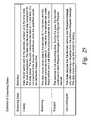
- FIG. 25is a table showing definitions of streaming states.
- FIG. 26is a flow diagram showing request and data messages transmitted between a data mover and a decoder.
- the systemincludes a video server 21 storing MPEG-2 encoded video data, several decoder arrays 19 , 20 , 22 for decoding the MPEG-2 encoded video data to produce a number of real-time video streams, and a control station 23 managed by an operator 24 .
- the operator 24for example, enters and edits a play list 25 specifying a sequence of video clips to be included in each video stream, and a time code (TC) at which each video clip is to begin.
- TCtime code
- the video server 21is a storage system for storing the video clips, each of which is a segment from an MPEG-2 Transport Stream (TS). Each clip includes a series of complete and contiguous groups of pictures (GOPs) in the MPEG-2 Transport Stream.
- a suitable video server 21is described in Duso et al. U.S. Pat. No. 5,892,915 issued Apr. 6, 1999, incorporated herein by reference. This kind of video server 21 is manufactured and sold by EMC Corporation, 35 Parkwood Dr., Hopkinton, Mass. 01748.
- the video server 21includes a cached disk storage subsystem 26 for storing the MPEG-2 encoded video clips, at least one controller server 27 , and a plurality of data mover computers 28 , 29 , and 30 for streaming the Transport Streams of the video clips.
- the clustering of the data movers 28 , 29 , 30 as a front end to the cached disk storage subsystem 26provides parallelism and scalability.
- Each of the data movers 28 , 29 , 30is a high-end commodity computer, providing the highest performance appropriate for a data mover at the lowest cost.
- the data moversmay communicate with each other and with the controller server 27 over a dedicated dual-redundant Ethernet connection 31 .
- the controller server 27also has a data link to the control station 23 .
- the controller server 27is a high-end commodity computer, and the control station 23 is a low-end commodity computer, such as a laptop computer.
- Each of the decoder arrays 19 , 20 , 22includes a plurality of MPEG-2 decoders 32 , 33 , 34 , 35 , 36 , 37 , video stream switches 38 , 39 , 40 , and a decoder controller 41 .
- the MPEG-2 decodersare arranged in pairs and each pair is associated with a respective video stream switch 38 , 39 , 40 so that each video stream switch selects the video stream output of one (designated “A”) or the other (designated “B”) of the decoders in the decoder pair associated with the video switch.
- each decoder in each decoder pair in the decoder array 22has a data port for a data streaming link 42 , 43 , 44 , 45 , 46 , 47 to a respective port in the data mover 28 for the pair.
- This data streaming linkfor example, is a bi-directional Ethernet link providing communications via the User Datagram Protocol (UDP).
- the respective data moversends data to the decoder and the decoder flow controls the data by using disconnects to control the data rate.
- the decoder controller 41has a control port for a bi-directional Ethernet link 48 to the data mover 28 using UDP.
- the controller server 27sends decoder control requests over the link 31 to the data mover 28 which sends the commands over the link 48 to the decoder controller 41 , and the decoder controller returns command responses over the link 48 to the data mover 28 .
- the decoder controller 41also has an asynchronous port for a bi-directional Ethernet link 49 to the data mover computer 28 using UDP.
- the decoder controllersends asynchronous status reports and edit messages over the link 49 to the data mover computer 28 .
- the decoder array 22It is desired to control the decoder array 22 in such a way that a real-time video stream is produced by seamless splicing of clips, and the spliced video stream is frame accurate and time accurate.
- the In-point and Out-point of the splicecan be freely selected, independent of the positions of the In-point and Out-point in the GOP structure of the MPEG encoded clips.
- the video streamcan be precisely specified by a play list 25 including, for each entry in the play list, a specification of a clip (e.g., a clip ID), a specification of a particular frame in the clip (e.g., a frame offset), and a starting time code for each clip (e.g., TC IN ).
- each decoder in the decoder array 22has a large frames buffer (shown in FIG. 4 and described further below) of decompressed video frames and pointers in the buffer that will allow the decoder to display any frame regardless of its MPEG type (I, B or P).
- the other decoder in the paircan be prepared for the display of a specified frame of a next clip at a specified time.
- the video switch of the decoder pairis toggled so that the video stream from the video switch displays the specified frame of the next clip at the specified time.
- Each of the decoder arrays 19 , 20has a construction and operation similar to the construction and operation of the decoder array 22 .
- the decoder array 19is linked to the data mover 29 for the exchange of control requests, data, asynchronous status reports and edit messages for the production of multiple concurrent video streams from MPEG-2 encoded data from the data mover 29 .
- the decoder array 20is linked to the data mover 30 for the exchange of control requests, data, asynchronous status reports and edit messages for the production of multiple concurrent video streams from MPEG-2 encoded data from the data mover 30 .
- each decoderhas the capability of operating faster than real-time when the decoder is being prepared for the display of a specified frame of a new clip at a specified time.
- a house clock generator 50synchronized to a global positioning system (GPS) clock signal, produces a common time base that is shared between the decoder array 22 and the video server 21 .
- GPSglobal positioning system
- Changes to the play list 25can be evaluated by the controller server 27 with reference to the house clock signal to schedule a data mover for the streaming of MPEG-2 coded video for a new clip from the cached disk storage 26 to one decoder in a decoder pair concurrent with the play-out of the current clip and just after the streaming of MPEG-2 coded video of the current clip to the other decoder in the decoder pair.
- the play list 25 and edit requests to the play list 25 from the operator 24 at the control systemare evaluated by the controller server on an admissions control basis and either rejected as untimely or accepted and converted into appropriate control commands to the data mover 28 and from there transmitted to the decoder controller 41 with substantial certainty that the control commands will be executed in time to produce a properly spliced video stream as specified by the play list.
- the controller server 27has a kind of feed forward control model of the requirements and capabilities of the data movers and decoders for execution of the commands in the control protocol and the data protocol.
- This feed forward control modelprovides the controller server 27 with the ability to determine whether or not the data mover and decoder operations can be scheduled in time in accordance with the play list and play list edits, and if so, to schedule them by forwarding appropriate commands to the data mover 28 and indirectly to the decoder controller 41 .
- the protocolsare exported to the decoder controller 41 and the decoders 32 , 33 , 34 , 35 , 36 , 37 with A/B switch on TC capability to allow the frame accuracy in time and space.
- the video server 21starts the operation of a selected one of the decoders and then the decoder requests the MPEG TS data from the respective data mover at a rate that will allow the decoder to decode the data.
- Each operation of stream start or switchis based on a TC and offset request from the video server as well as the preparation of the decoder that is off-air while the other decoder in the decoder pair is on air. In all cases there is a single channel of MPEG TS data streaming from the video server to the decoder pair.
- a first clip of MPEG-2 encoded video data 61is contained in the cached disk storage 26 .
- the data mover 28fetches blocks of data from the first clip 61 and stores them in a random access memory buffer 62 in the data mover 28 .
- the decoder 32includes a decoder data buffer 63 for storing MPEG-2 encoded video data, MPEG-2 decoder logic 64 for decoding the MPEG-2 encoded video data, and a video frames buffer 65 for storing frames of video data.
- the decoder 32fetches the blocks of data from the buffer 62 in the data mover 28 and stores them in the decoder data buffer 63 .
- the MPEG-2 decoder logic 64decodes the blocks of data in the decoder data buffer 63 to produce frames of video data and stores the frames of video data in the video frames buffer 65 .
- Data of a video frame having a current time codeis presented in real-time to the A/B switch 38 , and when the A/B switch is in the “A” channel selected state, the A/B switch outputs the real-time video stream from the decoder 32 .
- FIG. 2shows a “B” channel data path including a second clip 66 in cached disk storage 26 , a buffer 67 in the data mover 28 , a decoder data buffer 68 in the decoder 33 , MEPG-2 decoder logic 69 in the decoder 33 , and a video frames buffer 70 .
- the buffer 62 and the buffer 67share random access memory 71 in the data mover 28 , and generally speaking, when the buffer 62 is substantially full, the buffer 67 is substantially empty.
- the control station 23issues a series of requests to the controller server 27 of the form “play clip P f starting with frame F off at time TC IN .”
- the controller server 27sends the command to a data mover such as the data mover 28 which responds by comparing the specified time code TC IN to the current time code TC from the house clock 50 to see if the specified time code TC IN is prior in time by a predetermined threshold. If so, the data mover 28 forwards the request to a selected one of the decoder pair from which the video stream is to issue.
- the data mover 28then executes a routine 81 for fetching, from the cached disk storage ( 26 in FIG.
- the data mover 28obtains more precise information as to when the decoder 32 can decode the specified frame F off , and if the data mover 28 determines that the decoder can decode the specified frame by the specified time TC IN , then the data mover returns an acknowledgement to the controller server 27 . The data mover 28 then sends a display request to the decoder 32 .
- the decoder 32responds by performing a “pre-roll” operation that includes the fetching of the MPEG-2 encoded video from the buffer 62 in the data mover 28 to the decoder data buffer 63 , and decoding the encoded video up to the specified frame F off .
- the data mover 28monitors the “pre-roll” operation by applying a decoder model 82 to the information exchanged between the decoder data buffer 63 and the data mover buffer 62 to compute a video buffer level estimate, and to conclude that the “pre-roll” operation is progressing properly so long as the video buffer level estimate is within specified limits for the decoder 32 .
- the video frames buffer 65When the current time code TC from the house clock 50 matches the specified time code TC IN , the video frames buffer 65 outputs video data for the specified frame, and the decoder controller 41 switches the A/B switch 38 to select the video stream from the specified frame F off in the frames buffer.
- the decoder 32continues to fetch and decode MPEG-2 encoded video data for the specified clip P f until the data mover 28 sends a flush command to the decoder.
- FIG. 4shows the frames buffer 65 .
- the bufferis logically organized as a circular FIFO buffer.
- the buffer pointeris incremented or decremented in a modulo-N fashion, where N is the number of pointer addresses of random access memory in the buffer.
- the addresses PF 1 , PF 2 , PF 3 , PF 4 , PF 5 , PF 6 , and PF 7designate the starting addresses of respective video frames.
- the pointer value P outindicates the starting address of the last frame written into the buffer and to be read out of the buffer.
- video datacan be written to the address P in , and then P in is incremented. If the buffer is not empty, video data can be read from the address P out for display, and then P out is typically decremented, unless it is desired to keep the frame in the frames buffer, for example, is during a pause or freeze frame operation.
- a separate display pointer P DISPcan be used for display operations where it is desired to keep the video data in the buffer. To flush the entire video frames buffer, the pointer value P in , is set equal to the pointer value P out .
- FIG. 5shows data structures associated with the frames buffer.
- the frame pointersare arranged as a list including the number of frames in the list.
- a frame offsetF OFF1 , F OFF2 , F OFF3 , . . .
- TC 1 , TC 2 , TC 3 , . . .time code associated with each frame in the frame in the buffer. If there is a time code associated with a frame in the frame buffer, then the frame will remain in the frames buffer until the current time code becomes equal to the specified time code unless the frame is flushed from the frames buffer in response to a command from the decoder controller 41 .
- the decoderin order for a specified frame F OFF to be decoded, it may be necessary for the decoder to decode a number of frames preceding the frame F OFF in the MPEG-2 Transport Stream. If the specified frame F OFF is found in a closed GOP as shown in FIG. 6 , then the decoder must decode the I frame of the closed GOP in order to display the specified frame F OFF . If the specified frame F OFF is found in an open GOP and the specified frame is a “B” frame that references a frame in a preceding GOP, as shown in FIG. 7 , then the decoder must decode the I frame of the preceding GOP.
- FIG. 8is a flowchart of a procedure executed by a data mover to determine the frames that must be fetched for decoding of the specified frame F OFF .
- the data moverreceives the clip ID (P f ) and the frame specification F OFF .
- the data moverfinds and fetches the GOP including the specified frame F OFF .
- step 93if is the GOP is a closed GOP (as indicated by a CLOSED_GOP flag in the GOP header), then execution branches to step 94 to start decoding at the first frame (the I frame) of the GOP.
- step 93if the GOP is not a closed GOP, then execution continues to step 95 to determine whether or not the specified frame F OFF references a frame in a prior GOP.
- step 95a frame pointer is set to the frame offset F OFF .
- step 96if the frame is not a B frame, then the GOP structure is such that the frame will not reference a frame in a prior GOP, and execution branches to step 94 .
- step 96if the frame is a B frame, execution continues to step 97 to examine the B frame to determine whether it references a prior frame. If the B frame does not reference a prior frame, then execution branches from step 97 to step 94 .
- step 97if the B frame references a prior frame, then execution continues to step 98 .
- step 98if the prior frame is not in the same GOP, then execution branches to step 100 to find and fetch the prior GOP, and in step 101 , decoding is started at the first frame (the I frame) of the prior GOP.
- step 98if the prior frame is in the same GOP, then execution continues to step 99 to set the frame pointer to the prior frame. Execution loops back from step 99 to step 96 to continue the backward search to determine whether there is an indirect reference to a frame in a prior GOP.
- FIG. 9is the first sheet of a flowchart showing how the video system in FIG. 1 uses the decoder control protocol and the decoder data protocol to achieve frame accurate decoding and splicing of MPEG-2 encoded clips.
- the data mover computer of the video serverallocates an IP address to the decoder array controller port (for link 48 in FIG. 1 , for example) using a common IP protocol such as DHCP.
- the data moverestablishes a safe connection with each decoder array that is directly linked to the data mover.
- the control stationreceives from the operator a request to start a specified clip with or without specifying a TC IN or frame offset F OFF at which the clip is to be started.
- the display of the clipwill begin at the first frame in the clip in display order as soon as the first frame is decoded.
- the data moveropens the requested file and determines where in the clip the decoder needs to begin decoding for decoding of the frame with any specified TC IN or frame offset F OFF . If a particular frame is not specified, decoding begins with the first frame in the clip.
- the data moverpre-fills the data buffer of the decoder “A” with enough data to allow the decoder “A” to decode and fill its video frames buffer.
- step 105the data mover pre-fills the data buffer of the decoder “A” with enough data to allow the decoder “A” to decode and fill its video frames buffer. Execution continues from step 105 to step 106 in FIG. 10 .
- the data moversends any specified TC IN to the decoder “A”, or assigns a TC IN based on the house clock, and sends the specified or assigned TC IN to the decoder “A”.
- the house clockis shared between the video server and the decoder array for synchronization.
- the data moversends to the decoder “A” the TC of the first frame as well as the frame offset starting with an I frame and a GOP header, not necessarily the first GOP.
- the decoder “A”starts displaying the video frames starting with the one with the requested offset F OFF .
- the decoder “A”begins requesting MPEG-2 TS data from the data mover at a rate dictated by the bit rate of the decoding process. Execution continues from step 107 to step 108 in FIG. 11 .
- step 108 in FIG. 11the data mover delivers as much data as requested by the decoder “A” in a requested manner and not streaming in real time.
- step 109after the start of the play-out the data mover fetches a new play command and TC IN or generates a TC IN matching the last frame that will be played on the decoder channel “A”.
- step 110the data mover pre-rolls data to the decoder “B” for play-out on the decoder channel “B”.
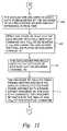
- step 111the decoder “B” fills its video frames buffer and sets its display pointer to the first frame defined by the frame offset specified by the new play command. The decoder “B” waits for the time of the TC IN of the new play command. Execution continues from step 111 to step 112 in FIG. 12 .
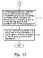
- step 112 in FIG. 12at the requested TC IN , the A/B switch switches the video stream from the decoder channel “A” to the decoder channel “B”.
- the play-out from the decoder “A”stops at the end of the current GOP in the decoder “A”.
- step 113the data mover flushes the decoder “A” and prepares to cue a new clip into the decoder “A” when requested by the operator. Steps 103 to 113 can be repeated to play additional clips in the play list.
- the controller server 27 and each data mover, such as data mover 28are programmed with various functions and data structures for sending data and control commands to the decoder array.
- the controller server 27is programmed with a VideoService function layered over a device driver, 122 , such as a Small Computer System Interface (SCSI) driver, for example.
- the VideoService functionperforms configuration discovery by a scan of the data movers connected to a decoder array controller.
- the decoder controlleris automatically configurable as an external connected device.
- VideoServicerecognizes the unique inquiry string from the decoder array, it sends an appropriate configuration command to each data mover connected to one or more decoder arrays.
- the data mover 28is programmed with a CM_Streams function which handles data mover buffer management, interfaces with the cached disk storage, and manage streaming from the data mover buffers. There is no need to do any “at time” processing nor any splicing in the data mover.
- the CM_Streams functionaccesses various stream classes described further below with reference to FIG. 14 .
- the data mover 28is also programmed with a network layer CM_Net function tasked with delivering the data to the decoders of the respective decoder pair interfaced to the data mover.
- the CM_Streams functionis layered over the CM_Net function, and the CM_Net function is in turn layered over a device driver 126 for the data links from the data mover to the decoders of the respective decoder pair interfaced to the data mover.
- the CM_Net functionaccesses an Endpoint class 127 and Player classes 128 , which provide a generic abstraction of the network seen by the data mover regardless of the device or network type.
- the Endpoint class 127provides a transparent naming mechanism, while the Player classes 128 abstract the actual output channel.
- a data mover threadis instantiated for the endpoint.
- the threadprovides support for those times when the stream or device has gone idle.
- the threadservices both of the ports for the two decoders in a decoder pair when the decoder pair is acting in the dual decoder mode.
- the player or device drivercan query the stream to determine whether the play-out will use the dual-decoder model or will be streaming via a single decoder. If the stream is a VRP type stream, then the player code sends all of the data through the “A” decoder and no attempt is made to switch over to the “B” decoder. Likewise, the same approach can be taken to support a “raw” data format.
- FIG. 14shows a hierarchy of stream classes.
- a CM_Stream class 131is a base class for streams that deliver data to either one or a pair of decoders.
- the CM_Stream classdoes not itself directly support “at time” operations, although it supports some minimal MPEG processing such as positioning by frame and PID re-mapping, but not splicing, padding, or “at time” scheduling.
- the CM_Stream classmakes available a number of interfaces to the CM_Net function, including:
- CM_IOBuffer*takeBuffer1st(); CM_IOBuffer* takeBuffer2nd(); void clipStart(); void clipDone(); void decoderError();
- the stream class CM_PlayStream 132is invoked for playing a stream, and the class CMPlayListStream 133 is invoked for playing a next stream from the play list.
- the class CM_DoubleStream 134is invoked for playing a stream from the next “A” or “B” channel of a decoder pair, by pre-rolling to the idle decoder and then switching channels.
- FIG. 15shows a hierarchy of the player classes 128 .
- Player instances of output channels for the streamsall derive from a CMPlayer base class 141 .
- a number of player interfacesare provided to pass the “at time” information to the player classes.
- the playeris also provided with the bit rate of each clip (this information is used to smooth and adjust data delivery rates). Finally, the player is informed of certain stream state changes, such as canceling a clip that has already been cued.
- the CMDoublePlayer class 142derived from the CMPlayer class 141 , serves as the base class for any dual decoder type device. It provides the methods required to support delivering data in either the single decoder mode (for VRP and “raw” data streams) and the dual decoder mode for “any frame at any time” support for MPEG streams.
- This member functionreturns a flag indicating whether the player type is a dual decoder type. This function overrides the function in the CMPlayer class and always returns TRUE.
- This member functionis the default operation for dual decoder player types.
- the default operationis to operate as a single decoder device. This is to make them backward compatible with existing stream types.
- New stream types that are dual decoder awarecan call clearSingle( ) to put the Player in dual decoder mode.
- driverThe following member functions are accessed by driver:
- This member functionis used to get the next buffer descriptor that points at the data to be played. This function is only valid when the player is in the single decoder mode.
- This member functionis used by the derived player instance to determine what mode the play-out is in.
- This functionis called when a clip is first introduced to the player.
- the functionis called with identifier, id, which is unique for the stream. Also, the total number of frames in the clip, frames; the number of frames to skip at the beginning of play, offset; and the time when the play is to start is provided.
- This functionis called to stop the play or pre-roll of a clip.
- the player or drivertakes action to stop the current play if the clip is already playing or cancels the pre-roll if the clip has not already started. Clips which have been previously identified to the player is via a startClip( ) are aborted. If the clip is not known to the player then the function returns TRUE.
- the modifClip( ) functionis used to change the parameters of a clip after it has been introduced to the player.
- the number of frames, the starting frame offset, and the time code to startcan all be changed.
- the functionreturns TRUE if the clip is known and the change can be made; otherwise it returns FALSE.
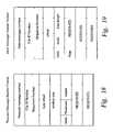
- FIG. 16is a table showing various commands in the control protocol used by a data mover of the video server for communicating with a decoder controller for controlling the decoder array.
- the control protocolis divided into four groups of messages, including a configuration group, a streaming group, asynchronous status report group, and an edit group. The first three of these groups are based on the RPC protocol.
- the Edit groupis based on SMPTE protocols.
- the configuration groupallows a data mover to determine the configuration of the decoder array and set up any configuration parameters.
- Commands in this groupinclude QueryStatus and Configure.
- the streaming groupcontrols delivery of streams (i.e., timing, clips, transition type). Commands in this group include PrerollClip, ModifyDisplayTime, CancelClipPreroll, PauseClip, ResumeClip, and ModifyClip.
- the asynchronous status report messagesprovide asynchronous reports of significant events from a decoder array to a data mover directly connected to the decoder array.
- Commands in this groupinclude ClipHasStarted, ClipHasEnded, ClipIsEnding, TrapMessage, and EditSummary.
- the edit messagesallow all decoders in the decoder array to be controlled by an edit control station. Commands in this group include Jog forward/backward, Shuttle forward/backward, Stop, Goto a specific timecode, and normal Play.
- Each decoderis referenced by an index in the range 0 to 5 and only the even-odd pairs are included in the respective decoder pairs.
- indices 0 and 1reference the two decoders ( 32 and 33 ) in the a first decoder pair
- indices 2 and 3reference the two decoders ( 34 and 35 ) in a second decoder pair
- indices 4 and 5reference the two decoders ( 36 and 37 ) in a third decoder pair.
- control protocolalso references the following set of common data types:
- the Configure commandallows a data mover to configure a decoder array that is directly connected to the data mover.
- Configure( )allows the data mover to set up the UDP port to be used for asynchronous status reports and Edit messages, and the operational mode of individual decoders.
- QueryStatus()returns the current status of the entire decoder array and allows the data mover to discover the configuration of the decoder array and, potentially, resume operation if the data mover crashes.
- /* Return status for control requests*/ enum DecoderArrayRequestStatus_t ⁇ RS_SUCCESS, RS_FAILURE, RS_ TOOLATE ⁇ ;
- Overall status of the decoder array (self test)*/ enum DecoderArrayTestStatus_t ⁇ ND_OK, ND_FAILED, ND_BUSY ⁇ ; /* Hardware version */ struct HWversion_t ⁇ unsigned int release; ⁇ ;
- a software versionhas three components to its name. The three components are separated by periods. For example, a software release name has the syntax major.minor.point, where each component is a member of the SWversion_t struct.
- the PrerollClip commandis used to inform a decoder that a new clip is being loaded and should be loaded into its buffers ready for play-out.
- PrerollMode_t*/ enum PrerollMode_t ⁇ PM_STREAM, PM_EDIT ⁇ ; struct PrerollData_t ⁇ int decoder; ClipID_t clip; FrameNumber_t frame_offset; DisplayTime_t display_time; Transition_t transition; PrerollMode_t mode; int aver_i_spacing; DisplayTime_t mark_in; DisplayTime_t mark_out ⁇ ;
- frame_offsetmay describe a frame in the following GOP.
- PrerollMode_tindicates whether the decoder is in Edit mode or Stream mode when pre-rolling. When a decoder is pre-rolling in Edit mode, the DisplayTime_t must be set to “DTT_NOW.”
- the ModifyDisplayTime commandallows the data mover to modify the display time associated with a clip which is already pre-rolled.
- the CancelClipPreroll commandis used to cancel streaming of a clip which has been prerolled.
- the PauseClip commandis used to pause the streaming or pre-rolling of a clip.
- PauseClip_t⁇ int decoder; ClipID_t clip; ⁇ ; DecoderArrayRequestStatus_t PauseClip(PauseClip_t);
- the ResumeClip commandis used to resume the streaming or pre- rolling of a clip.
- ResumeClip_t⁇ int decoder; ClipID_t clip; ⁇ ; ND_RequestStatus_t ResumeClip(ResumeClip_t);
- the ModifyClip commandis sent by a decoder in Edit mode to the data mover that is directly connected to the decoder.
- the decodercalculates the required I-frame spacing of the clip. This command is sent when the required I-frame spacing of the clip must be modified.
- the ClipHasStarted reportis issued when a decoder A-B switch occurs.
- the reportis sent by the decoder that is switched on-air and it is sent concurrent with the first frame.
- the decoder arraysaves this information so that a subsequent QueryStatus command may recover it.
- the informationis overwritten by the next ClipHasStarted report.
- the following fieldsare valid in the ClipActionInfo_t structure:
- the ClipHasEnded reportis issued when an clip has terminated because it has reached the end of the data stream. It is sent by the decoder that goes off-air and it is sent concurrent with the last frame. A subsequent clip may be pre-rolled for display sometime in the future or with no specified display time.
- the following fieldsare valid in the ClipActionInfo_t structure:
- the ClipIsEnding reportis issued by the on-air decoder.
- the decoderdetects the end of data flag in a Data message, it shall send the ClipIsEnding report. It is intended to be used by the data mover to send the on-air decoder a pre-roll command while it is still decoding on-air. By overlapping pre-rolling with streaming, the data mover can play shorter clips.
- the following fieldsare valid in the ClipActionlnfo_t structure:
- the control stationsends the Mark In (MI) and Mark Out (MO) data to the data mover which sends it in turn to the decoder it is controlling.
- the EditSummary reportis sent by the decoder to the data mover.
- the data moverwill pass the Mark In and Mark Out information to the control station.
- the trap messagehas the following structure:
- decoder_indexis the decoder index of the decoder initiating the report.
- a decoder_index value of “ ⁇ 1”shall be used to identify the decoder array as a whole.
- frame_countis the number of frames decoded from beginning of Clip until action_time.
- event_codeis a unique code that identifies a specified event that crosses a specified threshold.
- a thresholdcan be set to “Infinite,” i.e., the threshold will never be reached and the event will never be reported.
- a thresholdcan be set to “Now,” i.e., a single event causes an asynchronous status report. Threshold can be set to any value in between the two extremes.
- Editing commandsare sent to a single decoder in the decoder array from the control station.
- the decoderreturns the time code to the control station every frame.
- the physical protocol between the control station and the decoder arrayfor example, is SMPTE RP 170-1993.
- a single decodercan be put into the edit mode by receiving a PrerollClip command from the data mover with mode set to “Edit.” (All edit commands sent to the decoder before the decoder is put into the Edit state by the PrerollClip command, are ignored by the decoder.)
- the decoderpre-fills the clip up to the specified frame number and then stops.
- the decoderstops by sending request messages to the data mover with state set to “Stopped.”)
- the decoderwaits for edit commands from the control station.
- the edit commandsare: Stop, Shuttle, Jog forward/backward, Goto a specific timecode, and Play from a specific timecode.
- Jogis defined as playing out forward or backward frame by frame.
- Shuttle forward and backwardis defined as playing out at a speed not equal to real time.
- While the decoderis in Edit mode and either Jogging forward or Shuttling forward in less than real time, it sends periodic request messages to the data mover (as it does when streaming).
- the request messagesindicate the factor of real time that data is being decoded.
- the data movershould continue to stream data to the decoder.
- the decoderWhen the decoder is in Edit mode and receives a request for backward Jog/Shuttle or Shuttle forward faster than real time, the decoder sends the data mover a ModifyClip command, indicating whether the server should send all frames or I-frames only, and what the I-frame spacing should be.
- the data moverreplies with a PrerollClip command, with the edit flag set and the average I-frame spacing for the clip.
- the decoderpre-rolls the clip and executes the edit command at the specified frame number and with the specified I-frame spacing.
- the decodermay have to send the data mover a new ModifyClip command with a time code of the frame previous to the current frame. If the decoder can locate the previous time code in its buffer, it may not need to send a ModifyClip command to decode the previous frame.
- a decoderreceives the “Stop” command from the control station it freezes on the current frame and enters the “stopped” state.
- a decoderreceives the “Goto” command, it sends the ModifyClip command to the data mover, receives a PrerollClip command from the data mover, displays the specified frame and enters the “stopped” state.
- the decoderWhen the decoder sends a ModifyClip command to the data mover with mode set to I-frame only, the decoder tells the data mover to construct a stream with a specific I-frame spacing.
- the I-frame spacing and the decoder display ratedetermine the play-out speed of the decoder.
- the decoderuses the requested shuttle speed to calculate an I-frame spacing and display rate. It compares the new I-frame spacing with the I-frame spacing of the current clip. If the new I-frame spacing is different from the current I-frame spacing, a ModifyClip command is sent to the data mover.
- the data movers in the video server of FIG. 1use a data protocol for streaming continuous media data, such as MPEG-2 encoded TS data, to the decoders in the decoder array.
- the data protocolprovides for full flow-control, uniform data rates, and resilience to loss or delay of flow control messages.
- the protocolmakes use of multiple, concurrent “request” messages that unambiguously specify the total available buffer space (window).
- the number (or level) of redundant requestsis chosen to significantly reduce the possibility of a disruption in flow and to minimize the effect even if such a disruption does occur.
- the frequency of the “request” messagesmust be high enough to allow the data mover to stream media without interruption, even with a loss of several messages.
- the data moverreceives at least one request message of a group before the data mover fills up the window requested by the previous group of messages, in order to keep the data mover streaming.
- a request that is actually received by the data moverbegins a new redundancy group.
- the periodic “request” messagesshould nominally advertise a constant size window (i.e., regardless of the time base, the amount of data arriving should be equal to the amount of data being consumed).
- the overall rate of deliverycan be adjusted based on long term trend in changes in the window size.
- the protocolcan be used as a simple request-response protocol, without overlapped requests. However, this mode does not provide uniform delivery rates and lost messages can cause significant problems.
- a redundancy groupcan consist of a group of consecutive Request messages or a single Request message.
- a Request message that starts the data mover to stream data to a decoderis the start of a redundancy group.
- nFor a Redundancy Factor of n, up to n ⁇ 1 consecutive Request messages from a single decoder can be lost, and the data mover will continue to stream data to the decoder. If n consecutive Request messages are lost from a decoder, then the data mover stops streaming data to that decoder and only starts again when it successfully receives a Request message.
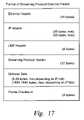
- FIG. 17shows the format of each message exchanged between the decoder and data mover. All messages are constrained to fit in a single Ethernet packet, in order to eliminate any need for re-assembly.
- a Request messageis sent from the decoder to the data mover at regular intervals.
- the messageconsists of a header only.
- FIG. 18shows a preferred format of the Request message header.
- the Request message number fieldis a 32-bit unsigned number that is assigned to each Request message by the decoder. The numbers are assigned sequentially.
- the Clip ID numberis a 64-bit unsigned number that consists of two 32-bit fields. The first field is an ID number. The second field is a sequence number. The sequence number indicates the version of a clip with the given ID number.
- the clip IDis assigned by the video server or data mover and sent to the decoder before the decoder sends out its first Request message.
- the clip IDidentifies the segment of a stored clip that is transmitted by the data mover to the decoder.
- the clip IDmay identify the entire stored clip or a segment of the stored clip.
- the offsetis a 32-bit unsigned number that counts the number of bytes of the clip that have been received by the decoder. Each time the offset field rolls over to its base address, a new section of the clip is being identified, which is 2 32 bytes offset from the previous base address.
- the window sizeis a 32-bit unsigned number. It indicates the number of available bytes in the decoder buffer.
- the state fieldis an 8-bit field with the values shown in the following table:
- the state fielddefines the states of the stream.
- the non-overlapped statemay be used by the data mover for testing.
- the decoderis not operated in a non-overlapped streaming state.
- the speed fieldis a 16-bit field used to hold an unsigned number.
- the fieldindicates to the data mover the speed at which the decoder is consuming data, relative to real time.
- the speedis normalized to 256. For example, a value of 256 indicates decoding at 1 ⁇ real time. A value less than 256 indicates a speed less than real time. A value greater than 256 indicates a speed greater than real time.
- a Data messageis sent from the data mover to the decoder.
- the messageconsists of a header followed by optional data bytes.
- FIG. 19shows the preferred format of the Data message header.
- the Data message number fieldis a 32-bit unsigned number that is assigned to each Data message by the data mover. The numbers are assigned sequentially.
- the Clip ID number fieldis defined in the Data message as it is defined in the Request message.
- the flag fieldis eight (8) bits and is defined in the following table:
- Bit Position Value Definition 0 1Data message indicates the end of End of Data Flag the clip 0: Data message does not indicate the end of the clip 1–7 Not Defined Not Defined The flag in the Data message is an “end of data” flag. It indicates either that the data in the message is the last of the data (if the length is greater than 0) or that there is no more data if the length equals 0. All protocol header data is represented in network order (“big-endian”) format.
- the data length fieldis 16-bit unsigned number and indicates the number of bytes of data included in the Data message.
- the decoderuses this field to calculate the offset value in the next Request message.
- FIG. 20shows in further detail the relationship of the offset to sections of a stored clip transmitted from the data mover to the decoder.
- a new section of the clipis being identified, which is 2 32 bytes offset from the previous base address.
- the offsetcan be used by the decoder to position data within a buffer (i.e., since data is not retransmitted, holes in the stream can occur).
- the offset fieldis used by the data mover to keep track of any “in flight” data packets when determining the true window size.
- the offsetis set by the decoder.
- the data moveruses the initial offset value in its initial Data message.
- FIG. 21shows an example of the setting of the offset value and the window size.
- the data moverkeeps track of the amount of data in the decoder data buffer (i.e., the “window size”) in order to decide how many data packets to send to keep the decoder data buffer as full as possible without overflow.
- the data movercomputes an estimate of the window size from the last window size reported by the decoder and the amount of data that has been transmitted by the data mover but not yet received by the decoder.
- FIG. 22shows a flow chart of the program executed by the data mover for the example of FIG. 21 .
- the data moverreceives the window (i.e., the decoder data buffer free space) from the decoder.
- the data movertransmits data packets to the decoder to fill the window.
- the data moverreceives a new window and offset from the decoder.
- the data movercomputes an estimated window size based on the data transmitted to but not received by the decoder by the time of the new window; for example, the estimated window is the sum of the new window and the new offset less the sum of the offset and the data length transmitted since the previous window.
- the data movertransmits more data packets to fill the estimated window.
- executionends if the end of the video stream for the clip has been reached; otherwise, execution loops back to step 163 .
- FIG. 23shows an example of the setting of the offset with lost data messages.
- the decodercomputes an estimate of the next offset that should be received from the data mover, and compares it to the offset received from the data mover. When the decoder finds a difference between the expected offset and the received offset, it concludes that data has been lost in transmission from the data mover.
- FIG. 24shows a flow chart of a program executed by the data mover in the example of FIG. 23 .
- the decoderreceives a data message including a data length and an offset.
- the decodercomputes a next estimated offset from the data length and the offset; for example, the next estimated offset is equal to the offset plus the data length from the data message.
- the decoderreceives a new data message including a new data length and a new offset.
- the estimated offsetis compared to the new offset. If the estimated offset is not equal to the new offset, then execution branches from step 174 to step 175 .
- step 175the decoder recognizes that data has been lost and waits for receipt of the lost data before attempting to decode the MPEG-2 TS data of the new data message or otherwise recovers from the data loss, for example, by freezing the last decoded video frame until the end of the clip or until receiving and decoding next I frame in the clip.
- step 176execution continues to step 176 .
- step 176execution also continues to step 176 from step 174 if the estimated offset is equal to the new offset.
- step 176execution ends if the end of the stream for the clip has been reached. Otherwise, execution loops from step 176 back to step 172 .
- the stream from the data mover to the decodercan exist in four unique states: “Cueing”, “Streaming,” “Stopped,” or “non-overlapped.”
- FIG. 25defines the four streaming states.
- the data moversends the decoder data, at least up to the time code that must be displayed.
- the data ratecan be at a rate convenient for the data mover.
- the decoderconsumes the data at 1 ⁇ real time. It is not important if the decoder underflows, since the underflow would be before the display time.
- the data moversends the decoder at 1 ⁇ real time and the decoder consumes the data at 1 ⁇ real time; the decoder can underflow/overflow and it will affect the picture presented to the viewer.
- the decoderIn the Stopped state, the decoder is not consuming data. During this state, the decoder continues to send Request messages at the configured Request interval.
- the decodersends a new Request message only after receiving a response from the previous Request message.
- the data movermay use this mode for testing.
- the data moverwould deliver data at a uniform rate. This simplifies management and loading of the storage, the data mover, memory, busses, and the network. If Request messages arrive before the transmission of all the data to fulfill the previous Request message, then data flow can be maintained. Increasing the frequency of transmission of Request messages (i.e., reducing the time between Request messages) allows uniform data flow even if some Request messages are delayed or completely lost.
- the decoderAfter the decoder receives a pre-roll command, it begins sending Request messages at the configured Request message interval, with the state field set to “Cueing.” After the decoder is pre-filled, the streaming state changes from “Cueing” to “Stopped”.
- the state is in the Request messageis set to “Stopped.”
- the streamenters the “Streaming” state and the decoder starts to display its program.
- the state in the Request messageis set to “Streaming.”
- the decoderWhile the decoder is decoding, it continues to send Request messages at the request interval, indicating the decode frame rate in the “speed” field.
- the data moverBased on the window size and the speed at which the data is consumed, the data mover computes when to start sending the decoder data and the rate at which to send the data. The data mover maintains the optimal buffer fullness in the decoder by adjusting the streaming rate.
- FIG. 26shows an example of how the data mover and a decoder transition between various streaming states.
- the decodersends Request messages, at the configured request interval, to the data mover with the state set to “Cueing.”
- the request rateis computed for a specific clip on a given decoder. It depends on a selected redundancy factor, available buffer space when data mover starts streaming data, and bit rate of clip.
- the data moverpre-fills the decoder buffer.
- the data moverwould begin to stream data to the decoder, to keep the decoder data buffer full.
- the data moveris given a redundancy factor and a request rate parameter, which is configurable for each decoder.
- the Redundancy Factoris defined as:
- the data moverwould begin streaming data when it receives a Request Rn after the display time. In the example of FIG. 24 , this Request Rn is Request 2 . The data mover would then stream the data at the bit rate of the stream. One hundred milliseconds later, the decoder would send Request Rn+1. If Rn+1 is lost or delayed, the data mover will continue to stream. One hundred milliseconds later, the decoder will send Request Rn+2, and 100 ms after that, it will send Rn+3. If up to three consecutive Request messages are lost, the data mover will still be able to stream data without stopping.
- the systemincludes a video server and an MPEG decoder array.
- the decoder arrayhas multiple decoder pairs, each pair having a video switch for switching from the video output of one decoder in the pair to the other at the occurrence of a specified time code. The switching may occur from a specified Out-point frame to a specified In-point frame, and Out-point and In-point frames can be any frame type at any location in the group of pictures (GOP) structure.
- the video serveris linked to multiple decoder arrays.
- the video serverhas a controller server linked to a number of data mover computers.
- Each decoder arrayis directly linked to a respective one of the data mover computers.
- Each data mover computeruse a control protocol to control the decoder array or decoder arrays to which is directly linked by sending control requests to the decoder controller in each decoder array.
- Each decoderuses a data protocol to request data from the respective data mover computer to which the decoder is directly linked.
- the control commandsinclude configuration commands to allow the data mover to determine a configuration of the decoder array and to set up configuration parameters, streaming commands to control the In-points and Out-points of the MPEG clips included in each of the multiple concurrent video streams, asynchronous status reports of significant events from the decoder array; and edit commands to allow the decoders in the decoder array to be controlled for editing content of the multiple concurrent video streams.
- the data protocolpermits the data movers to maintain the decoder data buffers in a substantially full condition, and permits the decoders to detect loss of data during transmission from the data mover to the decoder array.
- each data moveris directly linked to a respective one of the decoder arrays.
- each data movercould be directly linked to more than one decoder array.
- the data moverswere upgraded to double the processor speed and buffer memory of each data mover, then each data mover could be directly linked to a respective group of two decoder arrays.
- the decoder arraycould also be upgraded to double the processing speed of the decoder controller and to double the number of decoder pairs in each decoder, and in this case each upgraded data mover would control a respective one of the upgraded decoder arrays.
Landscapes
- Engineering & Computer Science (AREA)
- Multimedia (AREA)
- Signal Processing (AREA)
- Business, Economics & Management (AREA)
- Marketing (AREA)
- Compression Or Coding Systems Of Tv Signals (AREA)
- Television Signal Processing For Recording (AREA)
Abstract
Description
| CM_IOBuffer* takeBuffer1st(); | ||
| CM_IOBuffer* takeBuffer2nd(); | ||
| void | clipStart(); | ||
| void | clipDone(); | ||
| void | decoderError(); | ||
The
- boolean_t isDual(void);
- void clearSingle(void);
- BufferSource::Status takeBufferDescriptorList(DescriptorList*&);
- BufferSource::Status takeBufferDescriptorListA(DescriptorList*&);
- BufferSource::Status takeBufferDescriptorListB(DescriptorList*&);
- boolean_t isSingle(void);
- boolean_t startClip(cHandle_t id, ulong_t frames, int offset, timecode_t* tc);
- boolean_t abortClip(cHandle_t id);
- boolean_t modifyClip(cHandle_t id, ulong_t frames, int offset, timecode_t*tc);
| /* Frame number within a GOP in display order */ |
| typedef unsigned long FrameNumber_t; |
| /* Count of frames transmitted */ |
| typedef unsigned long FrameCount_t; |
| /* State of a decoder */ |
| enum decoderState_t {DS_STOPPED, DS_STREAMING, DS_PREROLLING}; |
| /* Clip identifier */ |
| struct ClipID_t { |
| unsigned long | id | |
| unsigned long | seq; |
| }; |
| /* Type of time code */ |
| enum DisplayTimeType_t { DTT_UNKNOWN, DTT_HOUSECLOCK, | |
| DTT_NOW }; |
| /* Time code */ |
| struct DisplayTime_t { |
| DisplayTimeType_t type; | |
| unsigned char hour; | |
| unsigned char minute; | |
| unsigned char second; | |
| unsigned char frame; | |
| }; |
| For DisplayTimeType_t set to DTT_UNKNOWN or DTT_NOW, hour, minute, |
| second, and frame shall be set to ‘0’. |
| /* Type of transition between clips */ |
| enum TransitionType_t { TT_NULL, TT_CUT, TT_FADE, TT_FADE_CUT, |
| TT_CUT_FADE, TT_DISSOLVE }; |
| /* Transition descriptor */ |
| struct Transition_t { |
| TransitionType_t type; | |
| int frames_to_transition; | |
| unsigned int alpha; |
| “alpha” is defined as the weighting factor assigned to the output of the on-air decoder |
| that is transitioning to off-air. “1 minus alpha” is the weighting factor assigned |
| to the output of the off-air decoder transitioning to on-air. |
| }; |
| /* Mode of an individual decoder */ |
| enum decoderMode_t { DM_UNCONFIGURED, DM_AB_GANGED, DM_ |
| SINGLE }; |
| /* Video Standard /* |
| enum VideoStandard_t {STD_NTSC, STD_PAL}; |
| /* Type of LTC signal being received */ |
| enum LTCtype_t { LTC_TYPE25, LTC_TYPE29, LTC_TYPE30 }; |
| /* Audio Embedding */ |
| enum decoderAudioEmbed_t {AE_ENABLED, AE_DISABLED}; |
| /* Error Concealment Mode */ |
| enum ErrorConcealment_t {EC_FREEZE_FRAME, EC_BLACK_FRAME }; |
| /* Configuration of an Individual decoder */ |
| struct decoderSetup_t { |
| int | decoder; | |
| unsigned short | flow_control_port; | |
| decoderMode_t | mode; | |
| ErrorConcealment_t | error_concealment; | |
| decoderAudioEmbed_t | audio_embed; | |
| int audio_delay_ms; | unsigned int request_interval_ms; }; |
| /* Configuration of the decoder array */ |
| struct DecoderArrayConfiguration_t { |
| struct in_addr | eth100_IP; | |
| unsigned short | async_port; | |
| VideoStandard_t | video_standard; | |
| LTCtype_t | ltc_type; | |
| decoderSetup_t | decoders<>; |
| }; |
| DecoderArrayRequestStatus_t Configure(DecoderArrayConfiguration_t); |
| The QueryStatus command may be sent to the decoder array at any time but is |
| primarily designed for use during startup for autoconfiguration. QueryStatus() returns the |
| current status of the entire decoder array and allows the data mover to discover the |
| configuration of the decoder array and, potentially, resume operation if the data mover |
| crashes. |
| /* Return status for control requests */ |
| enum DecoderArrayRequestStatus_t { RS_SUCCESS, RS_FAILURE, RS_ |
| TOOLATE }; |
| /* Overall status of the decoder array (self test) */ |
| enum DecoderArrayTestStatus_t { ND_OK, ND_FAILED, ND_BUSY }; |
| /* Hardware version */ |
| struct HWversion_t { |
| unsigned int | release; |
| }; |
A software version has three components to its name. The three components are separated by periods. For example, a software release name has the syntax major.minor.point, where each component is a member of the SWversion_t struct.
| /* Software version */ |
| struct SWversion_t |
| unsigned int | major; | |
| unsigned int | minor; | |
| unsigned int | point; }; |
| /* Status of the LTC signal */ |
| enum LTCstatus_t { LTC_NEVER_SEEN, LTC_ACQUIRED, LTC_ |
| LOST }; |
| /* Genlock Status */ |
| enum Genlock_t {GEN_LOCKED, GEN_NOTLOCKED}; |
| /* Link Status */ |
| enum LinkStatus_t { LS_OK, LS_ERRORED, LS_LOST }; |
| /* Current information for a single decoder */ |
| struct DecoderInfo_t { |
| DecoderMode_t | mode; | |
| DecoderState_t | state; | |
| unsigned int | buffer_size_bytes; | |
| ClipID_t | clip; | |
| DisplayTime_t | when; |
| /* set to 0,0 when there is no previous clip */ |
| ClipID_t | previous; | |
| DisplayTime_t | last_switch_time; | |
| FrameCount_t | frame_count; }; |
| /* Current status of the decoder array */ |
| struct DecoderArrayStatus_t { |
| /* decoder array Static Status Parameters */ |
| HWversion_t | hw_version; | |
| SWversion_t | sw_version; | |
| DecoderArrayTestStatus_t | status; |
| /* decoder array Dynamic Status Parameters */ |
| LTCstatus_t | ltc_status; | |
| Genlock_t | genlock_status; | |
| LinkStatus_t | eth100_link_status; | |
| LinkStatus_t | gbe_link_status; | |
| LinkStatus_t | rs422_1_status; | |
| LinkStatus_t | rs422_2_status; | |
| struct in_addr | eth100_ip; | |
| struct in_addr | gbe_ip; |
| /* DecoderArray Configurable Status Parameters */ |
| unsigned short | async_port; | |
| VideoStandard_t | video_standard; | |
| LTCtype_t | ltc_type; | |
| decoderSetup_t | decoder_setup<>; |
| /* Individual decoder Information */ |
| DecoderInfo_ | t decoders<>; }; |
| DecoderArrayStatus_t QueryStatus(void); |
| /* Decoder Preroll Mode */ |
| enum PrerollMode_t {PM_STREAM, PM_EDIT}; |
| struct PrerollData_t { |
| int | decoder; | |
| ClipID_t | clip; | |
| FrameNumber_t | frame_offset; | |
| DisplayTime_t | display_time; | |
| Transition_t | transition; | |
| PrerollMode_t | mode; | |
| int | aver_i_spacing; | |
| DisplayTime_t | mark_in; | |
| DisplayTime_t | mark_out |
| }; |
| struct ModifyData_t { |
| int | decoder; | |
| ClipID_t | clip; | |
| DisplayTime_t | display time; |
| }; |
| DecoderArrayRequestStatus_t ModifyDisplayTime(ModifyData_t); |
| The CancelClipPreroll command is used to cancel streaming of a clip |
| which has been prerolled. |
| struct CancelData_t { |
| int | decoder; | |
| ClipID_t | clip; |
| }; |
| DecoderArrayRequestStatus_t CancelClipPreroll(CancelData_t); |
| The PauseClip command is used to pause the streaming or pre-rolling |
| of a clip. |
| struct PauseClip_t { |
| int | decoder; | |
| ClipID_t | clip; |
| }; |
| DecoderArrayRequestStatus_t PauseClip(PauseClip_t); |
| The ResumeClip command is used to resume the streaming or pre- |
| rolling of a clip. |
| struct ResumeClip_t { |
| int | decoder; | |
| ClipID_t | clip; |
| }; |
| ND_RequestStatus_t ResumeClip(ResumeClip_t); |
| enum DecoderStreamMode_t {DSM_FRAMES, DSM_ALL_FRAMES}; |
| struct ModifyClip_t { |
| int | decoder; | |
| ClipID_t | clip; | |
| DisplayTime_t | time_code; | |
| DecoderStreamMode_t | mode; |
| int | i_space; | /* calculated by decoder*/ |
| }; |
| clip is the Clip ID of the last clip that was pre-rolled. |
| i_space is calculated by the decoder and can be a positive or negative number. A |
| negative value indicates that the data mover should play an I-frame only clip in reverse. |
| void ModifyClip(ModifyClip_t); |
| These reports are sent by the decoder array to the data mover when some |
| significant event has occurred. |
| struct ClipActionInfo_t { |
| int | decoder; | |
| ClipID_t | clip; | |
| DisplayTime_t | action_time; | |
| FrameCount_t | frame_count; |
| }; |
| decoder d | coder index of decoder brought on-air |
| clip | ID of clip just started to be displayed |
| action_time | House Clock time when clip started |
| frame_count | number of frames decoded for the previous clip; when no |
| previous clip exists, frame_count should be set to ‘0’ | |
| void ClipHasStarted(ClipActionInfo_t); |
| decoder | decoder index of decoder going off-air |
| clip | ID of clip just ended action_time House Clock time when |
| clip ended | |
| frame_count | number of frames decoded for the clip |
| void ClipHasEnded(ClipActionInfo_t); |
| decoder | decoder index of on-air decoder | ||
| clip | ID of the clip about to end | ||
| void ClipIsEnding(ClipActionInfo_t); |
| struct EditSummary_t { |
| int | decoder_index; | |
| ClipID_t | clip; | |
| DisplayTime_t | mark_in; | |
| DisplayTime_t | mark_out; |
| }; |
| void EditSummary(EditSummary_t); |
| struct TrapMessage_t { |
| int | decoder_index; | |
| ClipID_t | clip; | |
| DisplayTime_t | action_time; | |
| FrameCount_t | frame_count; | |
| int | event_code; |
| }; |
decoder_index is the decoder index of the decoder initiating the report. A decoder_index value of “−1” shall be used to identify the decoder array as a whole. frame_count is the number of frames decoded from beginning of Clip until action_time. event_code is a unique code that identifies a specified event that crosses a specified threshold. A threshold can be set to “Infinite,” i.e., the threshold will never be reached and the event will never be reported. A threshold can be set to “Now,” i.e., a single event causes an asynchronous status report. Threshold can be set to any value in between the two extremes.
- void TrapMessage(TrapMessage_t);
- enum ND_decoderStreamMode_t (Iframes, AllFrames);
| Definition | |||
| 0 | |||
| 1 | stopped | ||
| 2 | cueing | ||
| 3 | |||
| 4 | non-overlapped | ||
| 5–255 | Reserved | ||
| Bit | Value | Definition | |
| 0 | 1: Data message indicates the end of | End of Data Flag | |
| the clip | |||
| 0: Data message does not indicate the | |||
| end of the | |||
| 1–7 | Not Defined | Not Defined | |
The flag in the Data message is an “end of data” flag. It indicates either that the data in the message is the last of the data (if the length is greater than 0) or that there is no more data if the length equals 0. All protocol header data is represented in network order (“big-endian”) format.
The estimate of the window size of the decoder=(window size)Request message−((offset+data length)Data message−(offset)Request message)
- Redundancy Factor=nominal available buffer space (secs)×request rate (#requests/sec) Therefore, the data mover calculates the nominal available buffer space by dividing the Redundancy Factor by the request rate. As the encoder plays out a clip, the data mover tries to maintain the buffer level around the nominal level. For a redundancy factor of four and a request rate of 100 ms, the data mover begins to stream data to the decoder when the decoder has an available buffer of 0.40 seconds of space.
Claims (5)
Priority Applications (1)
| Application Number | Priority Date | Filing Date | Title |
|---|---|---|---|
| US09/834,427US7174561B2 (en) | 2001-04-13 | 2001-04-13 | MPEG dual-channel decoder data and control protocols for real-time video streaming |
Applications Claiming Priority (1)
| Application Number | Priority Date | Filing Date | Title |
|---|---|---|---|
| US09/834,427US7174561B2 (en) | 2001-04-13 | 2001-04-13 | MPEG dual-channel decoder data and control protocols for real-time video streaming |
Publications (2)
| Publication Number | Publication Date |
|---|---|
| US20030021346A1 US20030021346A1 (en) | 2003-01-30 |
| US7174561B2true US7174561B2 (en) | 2007-02-06 |
Family
ID=25266919
Family Applications (1)
| Application Number | Title | Priority Date | Filing Date |
|---|---|---|---|
| US09/834,427Expired - LifetimeUS7174561B2 (en) | 2001-04-13 | 2001-04-13 | MPEG dual-channel decoder data and control protocols for real-time video streaming |
Country Status (1)
| Country | Link |
|---|---|
| US (1) | US7174561B2 (en) |
Cited By (23)
| Publication number | Priority date | Publication date | Assignee | Title |
|---|---|---|---|---|
| US20050186988A1 (en)* | 2004-02-21 | 2005-08-25 | Samsung Electronics Co., Ltd. | Device and method for outputting data of a wireless terminal to an external device |
| US20050207449A1 (en)* | 2004-03-19 | 2005-09-22 | Broadlogic Network Technologies, Inc. | Method and system for providing faster channel switching in a digital broadcast system |
| US20060159184A1 (en)* | 2005-01-14 | 2006-07-20 | Samsung Electronics Co., Ltd. | System and method of decoding dual video signals |
| US20060212746A1 (en)* | 2005-03-21 | 2006-09-21 | Augustine Amegadzie | Selection of migration methods including partial read restore in distributed storage management |
| WO2006041996A3 (en)* | 2004-10-05 | 2007-05-03 | Skipjam Corp | Method for minimizing buffer delay effects in streaming digital content |
| US20070130493A1 (en)* | 2005-12-07 | 2007-06-07 | Microsoft Corporation | Feedback and Frame Synchronization between Media Encoders and Decoders |
| US20070139236A1 (en)* | 2005-12-21 | 2007-06-21 | Shastry Pavan V | Variable Length Coding Algorithm for Multiple Coding Modes |
| US20080181512A1 (en)* | 2007-01-29 | 2008-07-31 | Andrew Gavin | Image editing system and method |
| US20080183844A1 (en)* | 2007-01-26 | 2008-07-31 | Andrew Gavin | Real time online video editing system and method |
| US20080275997A1 (en)* | 2007-05-01 | 2008-11-06 | Andrew Gavin | System and method for flow control in web-based video editing system |
| US20100122159A1 (en)* | 2007-04-13 | 2010-05-13 | Canopus Co., Ltd. | Editing apparatus and an editing method |
| US20100272503A1 (en)* | 2009-04-22 | 2010-10-28 | As Ip Holdco, L.L.C. | Push and Turn Nut for Quick Faucet Installation |
| US7979752B1 (en)* | 2005-07-26 | 2011-07-12 | Cypress Semiconductor Corporation | Data loss protection switch system and method |
| US20130276038A1 (en)* | 2012-04-12 | 2013-10-17 | Kabushiki Kaisha Toshiba | Video server for controlling video signal output and video signal output control method |
| CN103517085A (en)* | 2013-10-22 | 2014-01-15 | 浪潮电子信息产业股份有限公司 | Method for implementing remote server management based on video decoding design |
| US8644691B1 (en) | 2012-11-29 | 2014-02-04 | Nvidia Corporation | Adaptively and accurately seeking a video frame of a video sequence rendered on a data processing device |
| US8776158B1 (en) | 2009-09-30 | 2014-07-08 | Emc Corporation | Asynchronous shifting windows caching for forward and backward video streaming |
| US20150046958A1 (en)* | 2013-08-06 | 2015-02-12 | Canon Kabushiki Kaisha | Communication apparatus that performs streaming distribution, method of controlling communication apparatus, reproduction apparatus, method of controlling reproduction apparatus, and storage medium |
| CN104581436A (en)* | 2015-01-28 | 2015-04-29 | 青岛海信宽带多媒体技术有限公司 | Video frame positioning method and device |
| CN107231328A (en)* | 2016-03-23 | 2017-10-03 | 福建星网锐捷通讯股份有限公司 | Method for real-time video transmission, device, equipment and system |
| US10375447B1 (en) | 2018-03-28 | 2019-08-06 | Carl Carpenter | Asynchronous video conversation systems and methods |
| US10727868B2 (en)* | 2018-12-03 | 2020-07-28 | Samsung Electronics Co., Ltd. | Apparatus and method for offset optimization for low-density parity-check (LDPC) code |
| US11856329B2 (en)* | 2008-04-11 | 2023-12-26 | Tivo Corporation | Dynamic advertisement stream replacement |
Families Citing this family (54)
| Publication number | Priority date | Publication date | Assignee | Title |
|---|---|---|---|---|
| US6980594B2 (en) | 2001-09-11 | 2005-12-27 | Emc Corporation | Generation of MPEG slow motion playout |
| US7161994B2 (en)* | 2001-09-17 | 2007-01-09 | Digeo, Inc. | System and method for shared decoding |
| US7167531B2 (en) | 2001-09-17 | 2007-01-23 | Digeo, Inc. | System and method for shared decoding using a data replay scheme |
| JP2003204540A (en)* | 2002-01-09 | 2003-07-18 | Ntt Docomo Inc | Content server, control method therefor, mobile communication terminal, control method therefor, program and recording medium |
| US8832754B2 (en) | 2002-05-03 | 2014-09-09 | Tvworks, Llc | System and method for providing synchronized events to a television application |
| US7343087B2 (en)* | 2002-11-12 | 2008-03-11 | Matsushita Electric Industrial Co., Ltd. | Data stream playback device and method, digital broadcast receiver and related computer program |
| JP4134164B2 (en)* | 2003-07-10 | 2008-08-13 | 富士通株式会社 | Media playback device |
| JP4577573B2 (en)* | 2003-07-14 | 2010-11-10 | ソニー株式会社 | COMMUNICATION DEVICE, SERVER DEVICE, INFORMATION PROCESSING METHOD, AND INFORMATION PROCESSING PROGRAM |
| US7382924B2 (en)* | 2003-08-14 | 2008-06-03 | Broadcom Corporation | Pixel reordering and selection logic |
| US20080126936A1 (en)* | 2003-08-21 | 2008-05-29 | Gary Williams | Electronic/software multimedia library control system and methods of use thereof |
| KR100556911B1 (en)* | 2003-12-05 | 2006-03-03 | 엘지전자 주식회사 | Structure of Video Data for Wireless Video Streaming Service |
| KR100640885B1 (en)* | 2004-01-27 | 2006-11-02 | 엘지전자 주식회사 | Video Buffer Control Unit for Dual Video Decoding |
| KR20080004503A (en)* | 2005-03-23 | 2008-01-09 | 알까뗄 루슨트 | System and method for performing playlist navigation for digital multimedia content from a network node |
| EP1904933A4 (en)* | 2005-04-18 | 2009-12-09 | Clearplay Inc | Apparatus, system and method for associating one or more filter files with a particular multimedia presentation |
| EP1889151A2 (en)* | 2005-05-21 | 2008-02-20 | Kula Media Group | Media distribution over a network |
| US8959125B2 (en)* | 2005-07-01 | 2015-02-17 | 226008 Ontario Inc. | File system having inverted hierarchical structure |
| US7873683B2 (en)* | 2005-07-01 | 2011-01-18 | Qnx Software Systems Gmbh & Co. Kg | File system having transaction record coalescing |
| US7970803B2 (en)* | 2005-07-01 | 2011-06-28 | Qnx Software Systems Gmbh & Co. Kg | Optimized startup verification of file system integrity |
| WO2007015047A2 (en)* | 2005-08-04 | 2007-02-08 | Nds Limited | Advanced digital tv system |
| US8135046B2 (en)* | 2005-11-11 | 2012-03-13 | Broadcom Corporation | Method and apparatus for demultiplexing, merging, and duplicating packetized elementary stream/program stream/elementary stream data |
| AU2006338233A1 (en)* | 2006-02-15 | 2007-08-23 | Sensormatic Electronics, LLC | RF switched RFID multiplexer |
| JP4297122B2 (en)* | 2006-03-01 | 2009-07-15 | ソニー株式会社 | Playback apparatus and playback method |
| JP4297121B2 (en)* | 2006-03-01 | 2009-07-15 | ソニー株式会社 | Playback apparatus and playback method |
| DE102006012449A1 (en)* | 2006-03-17 | 2007-09-20 | Benq Mobile Gmbh & Co. Ohg | Method of decoding a data stream and receiver |
| CN101064824A (en)* | 2006-04-28 | 2007-10-31 | 华为技术有限公司 | Method, system and apparatus for playing audio-video data |
| EP1879382B1 (en)* | 2006-07-10 | 2017-09-06 | Samsung Electronics Co., Ltd. | Multi-screen display apparatus and method for digital broadcast receiver |
| US7908276B2 (en) | 2006-08-25 | 2011-03-15 | Qnx Software Systems Gmbh & Co. Kg | Filesystem having a filename cache |
| US8566503B2 (en)* | 2006-08-25 | 2013-10-22 | Qnx Software Systems Limited | Multimedia filesystem having unified representation of content on diverse multimedia devices |
| US20080059510A1 (en)* | 2006-08-31 | 2008-03-06 | Daniel Cardamore | Multimedia system framework having layer consolidating access to multiple media devices |
| JP4901389B2 (en)* | 2006-09-20 | 2012-03-21 | 株式会社東芝 | Video server and material output method |
| JP4901390B2 (en)* | 2006-09-20 | 2012-03-21 | 株式会社東芝 | Video server and material output method |
| KR101228111B1 (en)* | 2006-11-01 | 2013-02-01 | 삼성전자주식회사 | Double register array buffer for motion compensation |
| US20080104267A1 (en)* | 2006-11-01 | 2008-05-01 | Sony Corporation | Systems and methods for reducing display latency between streaming digital media |
| US8341282B2 (en)* | 2006-11-21 | 2012-12-25 | Verizon Patent And Licensing Inc. | Hybrid buffer management |
| US20080147747A1 (en)* | 2006-12-14 | 2008-06-19 | Dan Cardamore | Media system having synchronization with preemptive prioritization of synchronization order |
| US8451317B2 (en)* | 2007-04-30 | 2013-05-28 | Hewlett-Packard Development Company, L.P. | Indexing a data stream |
| KR101437962B1 (en)* | 2007-06-26 | 2014-09-15 | 삼성전자주식회사 | Data processing apparatus and data processing method |
| US8179976B2 (en)* | 2008-01-11 | 2012-05-15 | Apple Inc. | Control of video decoder for reverse playback operation |
| CA2721700C (en)* | 2008-04-17 | 2019-07-16 | Sony Corporation | Dual-type of playback for multimedia content |
| US9047236B2 (en)* | 2008-06-06 | 2015-06-02 | Amazon Technologies, Inc. | Client side stream switching |
| JP5264349B2 (en)* | 2008-07-29 | 2013-08-14 | キヤノン株式会社 | Video receiving apparatus and video receiving method |
| KR20120067199A (en)* | 2010-12-15 | 2012-06-25 | 한국전자통신연구원 | Apparatus for encoding video and method for contolling thereof |
| EP2680599A1 (en)* | 2012-06-29 | 2014-01-01 | Thomson Licensing | Provision of a personalized media content |
| US8881213B2 (en)* | 2013-03-13 | 2014-11-04 | Verizon Patent And Licensing Inc. | Alignment of video frames |
| US9973748B1 (en)* | 2013-04-26 | 2018-05-15 | Mediatek Inc. | Multi-core video decoder system for decoding multiple coding rows by using multiple video decoder cores and related multi-core video decoding method |
| US10218981B2 (en)* | 2015-02-11 | 2019-02-26 | Wowza Media Systems, LLC | Clip generation based on multiple encodings of a media stream |
| US10284888B2 (en)* | 2017-06-03 | 2019-05-07 | Apple Inc. | Multiple live HLS streams |
| US10725942B2 (en) | 2018-11-09 | 2020-07-28 | Xilinx, Inc. | Streaming platform architecture for inter-kernel circuit communication for an integrated circuit |
| US10924430B2 (en)* | 2018-11-09 | 2021-02-16 | Xilinx, Inc. | Streaming platform flow and architecture for an integrated circuit |
| US10990547B2 (en) | 2019-08-11 | 2021-04-27 | Xilinx, Inc. | Dynamically reconfigurable networking using a programmable integrated circuit |
| US11232053B1 (en) | 2020-06-09 | 2022-01-25 | Xilinx, Inc. | Multi-host direct memory access system for integrated circuits |
| US11539770B1 (en) | 2021-03-15 | 2022-12-27 | Xilinx, Inc. | Host-to-kernel streaming support for disparate platforms |
| US11456951B1 (en) | 2021-04-08 | 2022-09-27 | Xilinx, Inc. | Flow table modification for network accelerators |
| US11606317B1 (en) | 2021-04-14 | 2023-03-14 | Xilinx, Inc. | Table based multi-function virtualization |
Citations (18)
| Publication number | Priority date | Publication date | Assignee | Title |
|---|---|---|---|---|
| US5231484A (en) | 1991-11-08 | 1993-07-27 | International Business Machines Corporation | Motion video compression system with adaptive bit allocation and quantization |
| US5381144A (en) | 1992-10-28 | 1995-01-10 | Matsushita Electric Industrial Co., Ltd. | Versatile escape run-level coder for digital video signal processing apparatus |
| US5534944A (en) | 1994-07-15 | 1996-07-09 | Matsushita Electric Corporation Of America | Method of splicing MPEG encoded video |
| US5565998A (en) | 1993-02-19 | 1996-10-15 | U.S. Philips Corporation | Identifying film frames in a video sequence |
| US5675384A (en) | 1995-10-03 | 1997-10-07 | Nec Usa, Inc. | VBR MPEG video encoding for ATM networks with dynamic bandwidth renegotiation |
| US5694170A (en) | 1995-04-06 | 1997-12-02 | International Business Machines Corporation | Video compression using multiple computing agents |
| US5742623A (en)* | 1995-08-04 | 1998-04-21 | General Instrument Corporation Of Delaware | Error detection and recovery for high rate isochronous data in MPEG-2 data streams |
| US5793897A (en) | 1993-12-16 | 1998-08-11 | Samsung Electronics Co., Ltd. | Adaptive variable-length coding and decoding methods for image data |
| US5838678A (en) | 1996-07-24 | 1998-11-17 | Davis; Joseph W. | Method and device for preprocessing streams of encoded data to facilitate decoding streams back-to back |
| US5859660A (en) | 1996-02-29 | 1999-01-12 | Perkins; Michael G. | Non-seamless splicing of audio-video transport streams |
| US5892915A (en) | 1997-04-25 | 1999-04-06 | Emc Corporation | System having client sending edit commands to server during transmission of continuous media from one clip in play list for editing the play list |
| US5959690A (en) | 1996-02-20 | 1999-09-28 | Sas Institute, Inc. | Method and apparatus for transitions and other special effects in digital motion video |
| US5969650A (en) | 1997-01-17 | 1999-10-19 | Matsushita Electric Industrial Co., Ltd. | Variable length coder with a small table size |
| US6018765A (en)* | 1996-01-23 | 2000-01-25 | Storage Concepts, Inc. | Multi-channel multimedia data server |
| US6124878A (en)* | 1996-12-20 | 2000-09-26 | Time Warner Cable, A Division Of Time Warner Enterainment Company, L.P. | Optimum bandwidth utilization in a shared cable system data channel |
| US6441832B1 (en)* | 1996-11-28 | 2002-08-27 | Sony Corporation | Hierarchical processing apparatus and hierarchical processing method for video and audio data |
| US20020129374A1 (en)* | 1991-11-25 | 2002-09-12 | Michael J. Freeman | Compressed digital-data seamless video switching system |
| US6470378B1 (en)* | 1999-03-31 | 2002-10-22 | Intel Corporation | Dynamic content customization in a clientserver environment |
- 2001
- 2001-04-13USUS09/834,427patent/US7174561B2/ennot_activeExpired - Lifetime
Patent Citations (18)
| Publication number | Priority date | Publication date | Assignee | Title |
|---|---|---|---|---|
| US5231484A (en) | 1991-11-08 | 1993-07-27 | International Business Machines Corporation | Motion video compression system with adaptive bit allocation and quantization |
| US20020129374A1 (en)* | 1991-11-25 | 2002-09-12 | Michael J. Freeman | Compressed digital-data seamless video switching system |
| US5381144A (en) | 1992-10-28 | 1995-01-10 | Matsushita Electric Industrial Co., Ltd. | Versatile escape run-level coder for digital video signal processing apparatus |
| US5565998A (en) | 1993-02-19 | 1996-10-15 | U.S. Philips Corporation | Identifying film frames in a video sequence |
| US5793897A (en) | 1993-12-16 | 1998-08-11 | Samsung Electronics Co., Ltd. | Adaptive variable-length coding and decoding methods for image data |
| US5534944A (en) | 1994-07-15 | 1996-07-09 | Matsushita Electric Corporation Of America | Method of splicing MPEG encoded video |
| US5694170A (en) | 1995-04-06 | 1997-12-02 | International Business Machines Corporation | Video compression using multiple computing agents |
| US5742623A (en)* | 1995-08-04 | 1998-04-21 | General Instrument Corporation Of Delaware | Error detection and recovery for high rate isochronous data in MPEG-2 data streams |
| US5675384A (en) | 1995-10-03 | 1997-10-07 | Nec Usa, Inc. | VBR MPEG video encoding for ATM networks with dynamic bandwidth renegotiation |
| US6018765A (en)* | 1996-01-23 | 2000-01-25 | Storage Concepts, Inc. | Multi-channel multimedia data server |
| US5959690A (en) | 1996-02-20 | 1999-09-28 | Sas Institute, Inc. | Method and apparatus for transitions and other special effects in digital motion video |
| US5859660A (en) | 1996-02-29 | 1999-01-12 | Perkins; Michael G. | Non-seamless splicing of audio-video transport streams |
| US5838678A (en) | 1996-07-24 | 1998-11-17 | Davis; Joseph W. | Method and device for preprocessing streams of encoded data to facilitate decoding streams back-to back |
| US6441832B1 (en)* | 1996-11-28 | 2002-08-27 | Sony Corporation | Hierarchical processing apparatus and hierarchical processing method for video and audio data |
| US6124878A (en)* | 1996-12-20 | 2000-09-26 | Time Warner Cable, A Division Of Time Warner Enterainment Company, L.P. | Optimum bandwidth utilization in a shared cable system data channel |
| US5969650A (en) | 1997-01-17 | 1999-10-19 | Matsushita Electric Industrial Co., Ltd. | Variable length coder with a small table size |
| US5892915A (en) | 1997-04-25 | 1999-04-06 | Emc Corporation | System having client sending edit commands to server during transmission of continuous media from one clip in play list for editing the play list |
| US6470378B1 (en)* | 1999-03-31 | 2002-10-22 | Intel Corporation | Dynamic content customization in a clientserver environment |
Non-Patent Citations (46)
| Title |
|---|
| "A Guide to MPEG Fundamentals and Protocol Analysis (Including DVB and ATSC)," Tektronix, In., Beaverton, Oregon, 1997, pp. 48 pages. |
| "Information technology-Generic coding of moving pictures an associated audio information: Video," International Standard, ISO/IEC 13818-2:1996(E), 211 pages. |
| "Information technology-Generic coding of moving pictures and associated audio information: Systems," International Standard, ISO/IEC 13818-1:1996(E), 136 pages. |
| "Information technology-Generic coding of moving pictures and associated audio information-Part 3: Audio," International Standard, ISO/IEC 13818-3:1995(E), 118 pages. |
| "MPEG-2: The basics of how it works," Hewlett Packard, published at least as early as Oct. 31, 1999, 17 pages. |
| "The Shape of MPEG," DV Magazine, vol. 4, No. 12, Dec. 1996, http://livedv.com/Mag/Dec96/Contents/mpeg/mpeg.html, 5 pages, published at least as early as Oct. 13, 1999. |
| A.T. Erdem and M.I. Sezan, "Multi-generation Characteristics of the MPEG Video Compression Standards," IEEE Proc. of ICIP-94, vol. II, 1994, pp. 933-937. |
| Adrienne Electronics Corporation-Home Page, http://www.adrielec.com/, 1 page; Functional Grouping of LTC/VITC, VTR Interface, and Video Products, http://www.adrielec.com/listing.htm, 2 pages; Adrienne Electronics Products and Price Listings Catalog, http://www.adrielec.com/shortfor.htm, 8 pages; AEC-BOX-Aug. 18, 1928 Standalone VITC and/or LTC Time Code Generator, http://www.adrielec.com/box28lit.htm, 4 pages; AEC-BOX-Aug. 18, 1928 Standalone LTC/VITC Time Code Reader, http://www.adrielec.com/box20lit.htm, 5 pages, published at least as early as Mar. 15, 2001. |
| Adrienne Electronics Corporation-Home Page, http://www.adrielec.com/, 1 page; Functional Grouping of LTC/VITC, VTR Interface, and Video Products, http://www.adrielec.com/listing.htm, 2 pages; Adrienne Electronics Products and Price Listings Catalog, http://www.adrielec.com/shortfor.htm, 8 pages; AEC-BOX-Aug. 18, 1928 Standalone VITC and/or LTC Time Code Generator, http://www.adrielec.com/box28lit.htm, 4 pages; AEC-BOX-Aug. 18, 1928 Standalone LTC/VITC Time Code Reader, http:www.adrielec.com/box20lit.htmm 5 pages, published at least as early as Mar. 15, 2001. |
| Alexandros Eleftheriadis and Dimitris Anastassiou, Constrained and General Dynamic Rate Shaping of Compressed Digital Video, Dept. of Electrical Engineering and Center for Telecommunications Research, Columbia University, New York, NY, Proceedings, 2<SUP>nd </SUP>IEEE International Conference on Image Processing (ICIP-95) , Arlington, VA, Oct. 1995, 4 pages. |
| Alexandros Eleftheriadis and Dimitris Anastassiou, Optimal Data Partitioning of MPEG-2 Coded Video, Dept. of Electrical and Center for Telecommunications Research, Columbia University, New York, NY, Proceedings, 1<SUP>st </SUP>International Conference on Image Processing (ICIP-94), Austin, Texas, Nov. 1994, 5 pages. |
| Andrew B. Watson, Joshua A. Solomon, Albert Ahumada, and Alan Gale, DCT Basis Function Visibility: Effects of Viewing Distance and Contrast Masking, (1994), 11 pages in B.E. Rogowitz (Ed.), Human Vision, Visual Processing and Digital Display IV (pp. 99-108), Bllington, WA, SPIE. |
| Anil K. Jain, Fundamentals of Digital Image Processing, Prentice Hall, Inc., Englewood Cliffs, New Jersey, 1989, Chapter 4: Image Sampling and Quantization and Chapter 5: Image Transforms, pp. 80-188. |
| B. Shen and I.K. Sethi, Conolution-Based Edge Detection for Image/Video in Block DCT Domain, Vision & Neural Networks Laboratory, Dept. of Computer Science, Wayne State University, Detroit, MI, To appear in Journal of Visual Communications and Image Representation, 19 pages. |
| Barry G. Haskell, Atul Puri, and Arun N. Netravali, Digital Video: An Introduction to MPEG-2, Chapman & Hall, New York, NY, 1997, pp. 1-279, 292-306, 369-421. |
| Barry G. Haskell, Atul Puri, and Arun N. Netravali, MPEG-2 Video Coding and Compression, Chp. 8, pp. 156-182, and "Interactive Television," Chp. 13, pp. 292-306, Digital Video: An Introduction to MPEG-2, Chapman & Hall, New York, NY, 1997. |
| Bo Shen and Ishwar K. Sethi, Block-Based Manipulations On Transform-Compressed Images and Videos, Vision and Neural Networks Laboratory, Dept. of Computer Science, Wayne State University, Detroit, MI, To appear in Multimedia Systems, 26 pages. |
| Bo Shen and Ishwar K. Sethi, Direct feature extraction from compressed images, Vision and Neural Networks Laboratory, Dept. of Computer Science, Wayne State University, Detroit, MI, SPIE vol. 2670, Storage & Retrieval for Image and Video Databases IV, 1996, 12 pages. |
| Bo Shen and Ishwar K. Sethi, Inner-Block Operations On Compressed Images, Vision and Neural Networks Laboratory, Dept. of Computer Science, Wayne State University, Detroit, MI, ACM Multimedia '95, San Francisco, CA, Nov. 5-9, 1995, 10 pages. |
| Bo Shen, Ishwar K. Sethi and Vasudev Bhaskaran, DCT Convolution and Its Application In Compressed Video Editing, Dept. of Computer Science, Wayne State University, Detroit, MI and Visual Computing Dept., Hewlett-Packard Laboratories, Palo Alto, CA, To appear in SPIE VCDIP '97, also submitted to IEEE Trans. Cir. and Sys. For Video Tech., 11 pages. |
| Boon-Lock Yeo, "On fast microscopic browsing of MPEG-compressed video," IBM T.J. Watson Research Center, Jan. 1998, Multimedia Systems 7, 1999, pp. 269-281. |
| C. Ward, C. Pecota, X. Lee, and G. Hughes, "Seamless Splicing for MPEG-2 Transport Stream Video Servers," SMPTE Journal, Dec. 1999, pp. 873-879. |
| Jerry D. Gibson, Toby Berger, Tom Lookabaugh, Dave Lindbergh, and Richard L. Baker, Digital Compression for Multimedia: Principles and Standards, Morgan Kaufmann Publishers, Inc., San Francisco, CA, 1998, Chapter 9: JPEG Still-Image Compression Standard, pp. 291-308, and Chapter 11: MPEG Compression, pp. 363-417. |
| Jill Boyce, John Henderson, and Larry Pearlstein, "An SDTV Decoder with HDTV Capability: An All-Format ATV Decoder," Hitachi America LTD., file://C:Fatima\67.gif, pp. 67-75, published at least as early as Jan. 12, 2000. |
| Leonardo Chiariglione, "MPEG and multimedia communications," CSELT, Torino Italy, http://www.cselt.stet.it/ufv/leonardo/paper/isce96.htm, 50 pages, published as least as early as Oct. 13, 1999. |
| M. Mohsenian, R. Rajagopalan, and C.A. Gonzales, "Single-pass constant- and variable-bit-rate MPEG-2 video compression," IBM J. Res. Develop., vol. 43, No. 4, Jul. 1999, pp. 489-509. |
| M. Perreira, and A. Lippman, "Re-codable video," IEEE Proc. of ICIP-94, vol. II, 1994, pp. 952-956. |
| MPEG Wizard: MPEG Real-Time External Encoder, http://www.duplexx.com/mpgwiz.html, MPEG Wizard: MPEG Real-Time Encoder-Features and Software, http://www.duplexx.com/mpgwiz<SUB>-</SUB>f.html, MPEG Wizard: MPEG Real-Time Encoder-Specs & Requirements, http://www.duplexx.com/mpgwiz<SUB>-r</SUB>.html, published at least as early as Mar. 19, 2001, 4 pages. |
| MPEG Wizard: MPEG Real-Time External Encoder, http://www.duplexx.com/mpgwiz.html, MPEG Wizard: MPEG Real-Time Encoder-Features and Software, http://www.duplexx.com/mpgwiz<SUB>-</SUB>f.html, MPEG Wizard: MPEG Reat-Time Encoder-Specs & Requirements, http://www.duplexx.com/mpgwiz<SUB>-</SUB>r.html, published at least as early as Mar. 19, 2001, 4 pages. |
| National P/N CLC020-SMPTE 259M Digital Video Serialized with Integrated Cable Driver, http://www.national.com/pf/CL/CLC020.html, published at least as early as Mar. 14, 2001, 3 pages. |
| National P/N CLC020-SMPTE 259M Digital Video Serializer with Integrated Cable Driver, http://www.national.com/pf/CL/CLC020.html, published at least as early as Mar. 14, 2001, 3 pages. |
| Nilesh V. Patel and Ishwar K. Sethi, Compressed Video Processing For Cut Detection, Vision and Neural Networks Laboratory, Dept. of Computer Science, Wayne State University, Detroit, MI, Oct. 1997, 26 pages. |
| Nilesh V. Patel and Ishwar K. Sethi, Video Shot Detection and Characterization for Video Databases, Vision and Neural Networks Laboratory, Dept. of Computer Science, Wayne State University, Detroit, MI, Oct. 1997, 22 pages. |
| Norm Hurst and Katie Cornog, "MPEG Splicing: A New Standard for Television-SMPTE 312M," SMPTE Journal, Nov. 1998, pp. 978-988. |
| Norm Hurst and Katie Cornog, "Splicing FAQ," http://www.mpeg.org/MPEG/splicing-FAW.html, 8 pages, published at least as early as Oct. 13, 1999. |
| Optivision MPEG-1 Encoder, http://brahma.imag.fr/Multimedia/jeudis/jeudi2/Optivision<SUB>-</SUB>mpeg1enc.html, published at least as early as Mar. 19, 2001, 3 pages. |
| O'Reilly Network Broadcast 2000 Brings DV Editing to Linus (Aug. 11, 2000), http://www.oreillynet.com/pub/a/network/2000/08/11/magazine/broadcase2000.html, published at least as early as Mar. 27, 2001, 3 pages; Broadcast 2000, http://heroinewarrior.com/bcast2000.php3, published at least as early as Mar. 27, 2001, 4 pages. |
| P.H. Westerink, R. Rajagopalan, and C.A. Gonzales, "Two-pass MPEG-2 variable-bit-rate encoding," IBM J. Res. Develop., vol. 43, No. 4, Jul. 1999, pp. 471-488. |
| Robert Mokry and Dimitris Anastassiou, "Minimal Error Drift in Frequency Scalability for Motion-Compensated DCT Coding," IEEE Transactions on Circuits and Systems for Video Technology, vol. 4, No. 4, Aug. 1994, pp. 392-406. |
| SMPTE 312M-1999, SMPTE Standard for Television, "Splice Points for MPEG-2 Transport Streams," Approved Apr. 8, 1999, The Society of Motion Picture and Television Engineers, White Plains, NY, 20 pages. |
| TDR600/RA, satellite uplink equipment, downlink, teleports, earth stations, amplifiers, antennas, http://www.usacanada.net/satellite/tdr600-ra.htm, published at least as early as Mar. 14, 2001, 2 pages. |
| TE-30, satellite uplink equipment, downlink, teleports, earth stations, amplifiers, antennas, http://www.usa.canada.net/satellite/te30.htm, published at least as early as Mar. 14, 2001, 3 pages. |
| TE-30, satellite uplink equipment, downlink, teleports, earth stations, amplifiers, antennas, http://www.usacanada.net/satellite/te30.htm, published as early as Mar. 14, 2001, 3 pages. |
| TE300A MPEG-2 Encoder, satellite uplink equipment, downlink, teleports, earth stations, amplifiers, antennas, http://www.usacanada.net/satellite/te300a.htm, published at least as early as Mar. 14, 2001, 3 pages. |
| TE600 MPEG-2 DSNG Encoder, satellite uplink equipment, downlink, teleports, earth stations, amplifiers, antennas, http://www.usacanada.net/satellite/te600.htm, published at least as early as Mar. 14, 2001, 3 pages. |
| Y. Nakajima, H. Hori, and T. Kanoh, "Rate Conversion of MPEG Coded Video by Requantization Process," IEEE Proc. of ICIP-95, vol. III, Sep. 1995, pp. 408-411. |
Cited By (47)
| Publication number | Priority date | Publication date | Assignee | Title |
|---|---|---|---|---|
| US10313730B2 (en) | 2004-02-21 | 2019-06-04 | Samsung Electronics Co., Ltd. | Device and method for outputting data of a wireless terminal to an external device |
| US20050186988A1 (en)* | 2004-02-21 | 2005-08-25 | Samsung Electronics Co., Ltd. | Device and method for outputting data of a wireless terminal to an external device |
| US8578429B2 (en)* | 2004-02-21 | 2013-11-05 | Samsung Electronics Co., Ltd. | Device and method for outputting data of a wireless terminal to an external device |
| US20050207449A1 (en)* | 2004-03-19 | 2005-09-22 | Broadlogic Network Technologies, Inc. | Method and system for providing faster channel switching in a digital broadcast system |
| US8249113B2 (en)* | 2004-03-19 | 2012-08-21 | Broadlogic Network Technologies, Inc. | Method and system for providing faster channel switching in a digital broadcast system |
| US8687656B2 (en) | 2004-03-19 | 2014-04-01 | Broadcom Corporation | Method and system for providing faster channel switching in a digital broadcast system |
| US9019995B2 (en) | 2004-03-19 | 2015-04-28 | Broadcom Corporation | Method and system for providing faster channel switching in a digital broadcast system |
| WO2006041996A3 (en)* | 2004-10-05 | 2007-05-03 | Skipjam Corp | Method for minimizing buffer delay effects in streaming digital content |
| US20060159184A1 (en)* | 2005-01-14 | 2006-07-20 | Samsung Electronics Co., Ltd. | System and method of decoding dual video signals |
| US7864866B2 (en)* | 2005-01-14 | 2011-01-04 | Samsung Electronics Co., Ltd. | System and method of decoding dual video signals |
| US20060212746A1 (en)* | 2005-03-21 | 2006-09-21 | Augustine Amegadzie | Selection of migration methods including partial read restore in distributed storage management |
| US8055724B2 (en) | 2005-03-21 | 2011-11-08 | Emc Corporation | Selection of migration methods including partial read restore in distributed storage management |
| US7979752B1 (en)* | 2005-07-26 | 2011-07-12 | Cypress Semiconductor Corporation | Data loss protection switch system and method |
| US8381081B1 (en) | 2005-07-26 | 2013-02-19 | Cypress Semiconductor Corporation | Data loss protection switch system and method |
| US20070130493A1 (en)* | 2005-12-07 | 2007-06-07 | Microsoft Corporation | Feedback and Frame Synchronization between Media Encoders and Decoders |
| US7716551B2 (en)* | 2005-12-07 | 2010-05-11 | Microsoft Corporation | Feedback and frame synchronization between media encoders and decoders |
| US7345601B2 (en)* | 2005-12-21 | 2008-03-18 | Texas Instruments Incorporated | Variable length coding algorithm for multiple coding modes |
| US20070139236A1 (en)* | 2005-12-21 | 2007-06-21 | Shastry Pavan V | Variable Length Coding Algorithm for Multiple Coding Modes |
| US8286069B2 (en) | 2007-01-26 | 2012-10-09 | Myspace Llc | System and method for editing web-based video |
| US20080183608A1 (en)* | 2007-01-26 | 2008-07-31 | Andrew Gavin | Payment system and method for web-based video editing system |
| US20080183844A1 (en)* | 2007-01-26 | 2008-07-31 | Andrew Gavin | Real time online video editing system and method |
| US20080212936A1 (en)* | 2007-01-26 | 2008-09-04 | Andrew Gavin | System and method for editing web-based video |
| US20080181512A1 (en)* | 2007-01-29 | 2008-07-31 | Andrew Gavin | Image editing system and method |
| US8218830B2 (en) | 2007-01-29 | 2012-07-10 | Myspace Llc | Image editing system and method |
| US20100122159A1 (en)* | 2007-04-13 | 2010-05-13 | Canopus Co., Ltd. | Editing apparatus and an editing method |
| US9015583B2 (en)* | 2007-04-13 | 2015-04-21 | Gvbb Holdings S.A.R.L. | Editing apparatus and an editing method |
| US8898563B2 (en)* | 2007-04-13 | 2014-11-25 | Gvbb Holdings S.A.R.L. | Editing apparatus and an editing method |
| US20150012823A1 (en)* | 2007-04-13 | 2015-01-08 | Gvbb Holdings S.A.R.L. | Editing apparatus and an editing method |
| US20080275997A1 (en)* | 2007-05-01 | 2008-11-06 | Andrew Gavin | System and method for flow control in web-based video editing system |
| US7934011B2 (en)* | 2007-05-01 | 2011-04-26 | Flektor, Inc. | System and method for flow control in web-based video editing system |
| US11856329B2 (en)* | 2008-04-11 | 2023-12-26 | Tivo Corporation | Dynamic advertisement stream replacement |
| US12289562B2 (en) | 2008-04-11 | 2025-04-29 | Adeia Media Holdings Llc | Dynamic advertisement stream replacement |
| US20100272503A1 (en)* | 2009-04-22 | 2010-10-28 | As Ip Holdco, L.L.C. | Push and Turn Nut for Quick Faucet Installation |
| US8776158B1 (en) | 2009-09-30 | 2014-07-08 | Emc Corporation | Asynchronous shifting windows caching for forward and backward video streaming |
| US20130276038A1 (en)* | 2012-04-12 | 2013-10-17 | Kabushiki Kaisha Toshiba | Video server for controlling video signal output and video signal output control method |
| US8732774B2 (en)* | 2012-04-12 | 2014-05-20 | Kabushiki Kaisha Toshiba | Video server for controlling video signal output and video signal output control method |
| US8644691B1 (en) | 2012-11-29 | 2014-02-04 | Nvidia Corporation | Adaptively and accurately seeking a video frame of a video sequence rendered on a data processing device |
| US20150046958A1 (en)* | 2013-08-06 | 2015-02-12 | Canon Kabushiki Kaisha | Communication apparatus that performs streaming distribution, method of controlling communication apparatus, reproduction apparatus, method of controlling reproduction apparatus, and storage medium |
| US9338481B2 (en)* | 2013-08-06 | 2016-05-10 | Canon Kabushiki Kaisha | Communication apparatus that performs streaming distribution, method of controlling communication apparatus, reproduction apparatus, method of controlling reproduction apparatus, and storage medium |
| CN103517085A (en)* | 2013-10-22 | 2014-01-15 | 浪潮电子信息产业股份有限公司 | Method for implementing remote server management based on video decoding design |
| CN103517085B (en)* | 2013-10-22 | 2017-05-10 | 浪潮电子信息产业股份有限公司 | Method for implementing remote server management based on video decoding design |
| CN104581436B (en)* | 2015-01-28 | 2017-12-05 | 青岛海信宽带多媒体技术有限公司 | A kind of frame of video localization method and device |
| CN104581436A (en)* | 2015-01-28 | 2015-04-29 | 青岛海信宽带多媒体技术有限公司 | Video frame positioning method and device |
| CN107231328A (en)* | 2016-03-23 | 2017-10-03 | 福建星网锐捷通讯股份有限公司 | Method for real-time video transmission, device, equipment and system |
| US10375447B1 (en) | 2018-03-28 | 2019-08-06 | Carl Carpenter | Asynchronous video conversation systems and methods |
| US10727868B2 (en)* | 2018-12-03 | 2020-07-28 | Samsung Electronics Co., Ltd. | Apparatus and method for offset optimization for low-density parity-check (LDPC) code |
| US11290127B2 (en) | 2018-12-03 | 2022-03-29 | Samsung Electronics Co., Ltd | Apparatus and method for offset optimization for low-density parity-check (LDPC) code |
Also Published As
| Publication number | Publication date |
|---|---|
| US20030021346A1 (en) | 2003-01-30 |
Similar Documents
| Publication | Publication Date | Title |
|---|---|---|
| US7174561B2 (en) | MPEG dual-channel decoder data and control protocols for real-time video streaming | |
| US6907081B2 (en) | MPEG encoder control protocol for on-line encoding and MPEG data storage | |
| CA2234490C (en) | Timing correction method and apparatus | |
| US6137834A (en) | Method and apparatus for splicing compressed information streams | |
| US6038000A (en) | Information stream syntax for indicating the presence of a splice point | |
| JP4157617B2 (en) | Method and apparatus for information stream frame synchronization | |
| US7096481B1 (en) | Preparation of metadata for splicing of encoded MPEG video and audio | |
| US5859660A (en) | Non-seamless splicing of audio-video transport streams | |
| US6792047B1 (en) | Real time processing and streaming of spliced encoded MPEG video and associated audio | |
| US6678332B1 (en) | Seamless splicing of encoded MPEG video and audio | |
| US6912251B1 (en) | Frame-accurate seamless splicing of information streams | |
| EP1879347B1 (en) | System and method of audio/video streaming | |
| EP1002424B1 (en) | Processing coded video | |
| CN103535027B (en) | The method for handling the sequence of encoded video frame | |
| KR101250825B1 (en) | Fast video channel change | |
| JPH11501786A (en) | Compressed video signal receiving method | |
| CA2303149C (en) | Seamless splicing of compressed video programs | |
| EP0954924A1 (en) | Information stream syntax for indicating the presence of a splice point | |
| US11172238B1 (en) | Multiple view streaming | |
| JP3749715B2 (en) | Image data transmitting apparatus and image data transmitting method | |
| KR100517794B1 (en) | Method and apparatus for splicing compressed information streams | |
| Wimmer | DV/HDV tape drive synchronization for immediate preview of dual camera recordings |
Legal Events
| Date | Code | Title | Description |
|---|---|---|---|
| AS | Assignment | Owner name:EMC CORPORATION, MASSACHUSETTS Free format text:ASSIGNMENT OF ASSIGNORS INTEREST;ASSIGNORS:BIXBY, PETER;FORECAST, JOHN;HULTIN, WILLIAM O.;AND OTHERS;REEL/FRAME:011713/0069 Effective date:20010413 | |
| STCF | Information on status: patent grant | Free format text:PATENTED CASE | |
| CC | Certificate of correction | ||
| FPAY | Fee payment | Year of fee payment:4 | |
| FEPP | Fee payment procedure | Free format text:PAYOR NUMBER ASSIGNED (ORIGINAL EVENT CODE: ASPN); ENTITY STATUS OF PATENT OWNER: LARGE ENTITY | |
| FPAY | Fee payment | Year of fee payment:8 | |
| AS | Assignment | Owner name:THE BANK OF NEW YORK MELLON TRUST COMPANY, N.A., AS NOTES COLLATERAL AGENT, TEXAS Free format text:SECURITY AGREEMENT;ASSIGNORS:ASAP SOFTWARE EXPRESS, INC.;AVENTAIL LLC;CREDANT TECHNOLOGIES, INC.;AND OTHERS;REEL/FRAME:040136/0001 Effective date:20160907 Owner name:CREDIT SUISSE AG, CAYMAN ISLANDS BRANCH, AS COLLATERAL AGENT, NORTH CAROLINA Free format text:SECURITY AGREEMENT;ASSIGNORS:ASAP SOFTWARE EXPRESS, INC.;AVENTAIL LLC;CREDANT TECHNOLOGIES, INC.;AND OTHERS;REEL/FRAME:040134/0001 Effective date:20160907 Owner name:CREDIT SUISSE AG, CAYMAN ISLANDS BRANCH, AS COLLAT Free format text:SECURITY AGREEMENT;ASSIGNORS:ASAP SOFTWARE EXPRESS, INC.;AVENTAIL LLC;CREDANT TECHNOLOGIES, INC.;AND OTHERS;REEL/FRAME:040134/0001 Effective date:20160907 Owner name:THE BANK OF NEW YORK MELLON TRUST COMPANY, N.A., A Free format text:SECURITY AGREEMENT;ASSIGNORS:ASAP SOFTWARE EXPRESS, INC.;AVENTAIL LLC;CREDANT TECHNOLOGIES, INC.;AND OTHERS;REEL/FRAME:040136/0001 Effective date:20160907 | |
| AS | Assignment | Owner name:EMC IP HOLDING COMPANY LLC, MASSACHUSETTS Free format text:ASSIGNMENT OF ASSIGNORS INTEREST;ASSIGNOR:EMC CORPORATION;REEL/FRAME:040203/0001 Effective date:20160906 | |
| MAFP | Maintenance fee payment | Free format text:PAYMENT OF MAINTENANCE FEE, 12TH YEAR, LARGE ENTITY (ORIGINAL EVENT CODE: M1553) Year of fee payment:12 | |
| AS | Assignment | Owner name:THE BANK OF NEW YORK MELLON TRUST COMPANY, N.A., T Free format text:SECURITY AGREEMENT;ASSIGNORS:CREDANT TECHNOLOGIES, INC.;DELL INTERNATIONAL L.L.C.;DELL MARKETING L.P.;AND OTHERS;REEL/FRAME:049452/0223 Effective date:20190320 Owner name:THE BANK OF NEW YORK MELLON TRUST COMPANY, N.A., TEXAS Free format text:SECURITY AGREEMENT;ASSIGNORS:CREDANT TECHNOLOGIES, INC.;DELL INTERNATIONAL L.L.C.;DELL MARKETING L.P.;AND OTHERS;REEL/FRAME:049452/0223 Effective date:20190320 | |
| AS | Assignment | Owner name:THE BANK OF NEW YORK MELLON TRUST COMPANY, N.A., TEXAS Free format text:SECURITY AGREEMENT;ASSIGNORS:CREDANT TECHNOLOGIES INC.;DELL INTERNATIONAL L.L.C.;DELL MARKETING L.P.;AND OTHERS;REEL/FRAME:053546/0001 Effective date:20200409 | |
| AS | Assignment | Owner name:WYSE TECHNOLOGY L.L.C., CALIFORNIA Free format text:RELEASE BY SECURED PARTY;ASSIGNOR:CREDIT SUISSE AG, CAYMAN ISLANDS BRANCH;REEL/FRAME:058216/0001 Effective date:20211101 Owner name:SCALEIO LLC, MASSACHUSETTS Free format text:RELEASE BY SECURED PARTY;ASSIGNOR:CREDIT SUISSE AG, CAYMAN ISLANDS BRANCH;REEL/FRAME:058216/0001 Effective date:20211101 Owner name:MOZY, INC., WASHINGTON Free format text:RELEASE BY SECURED PARTY;ASSIGNOR:CREDIT SUISSE AG, CAYMAN ISLANDS BRANCH;REEL/FRAME:058216/0001 Effective date:20211101 Owner name:MAGINATICS LLC, CALIFORNIA Free format text:RELEASE BY SECURED PARTY;ASSIGNOR:CREDIT SUISSE AG, CAYMAN ISLANDS BRANCH;REEL/FRAME:058216/0001 Effective date:20211101 Owner name:FORCE10 NETWORKS, INC., CALIFORNIA Free format text:RELEASE BY SECURED PARTY;ASSIGNOR:CREDIT SUISSE AG, CAYMAN ISLANDS BRANCH;REEL/FRAME:058216/0001 Effective date:20211101 Owner name:EMC IP HOLDING COMPANY LLC, TEXAS Free format text:RELEASE BY SECURED PARTY;ASSIGNOR:CREDIT SUISSE AG, CAYMAN ISLANDS BRANCH;REEL/FRAME:058216/0001 Effective date:20211101 Owner name:EMC CORPORATION, MASSACHUSETTS Free format text:RELEASE BY SECURED PARTY;ASSIGNOR:CREDIT SUISSE AG, CAYMAN ISLANDS BRANCH;REEL/FRAME:058216/0001 Effective date:20211101 Owner name:DELL SYSTEMS CORPORATION, TEXAS Free format text:RELEASE BY SECURED PARTY;ASSIGNOR:CREDIT SUISSE AG, CAYMAN ISLANDS BRANCH;REEL/FRAME:058216/0001 Effective date:20211101 Owner name:DELL SOFTWARE INC., CALIFORNIA Free format text:RELEASE BY SECURED PARTY;ASSIGNOR:CREDIT SUISSE AG, CAYMAN ISLANDS BRANCH;REEL/FRAME:058216/0001 Effective date:20211101 Owner name:DELL PRODUCTS L.P., TEXAS Free format text:RELEASE BY SECURED PARTY;ASSIGNOR:CREDIT SUISSE AG, CAYMAN ISLANDS BRANCH;REEL/FRAME:058216/0001 Effective date:20211101 Owner name:DELL MARKETING L.P., TEXAS Free format text:RELEASE BY SECURED PARTY;ASSIGNOR:CREDIT SUISSE AG, CAYMAN ISLANDS BRANCH;REEL/FRAME:058216/0001 Effective date:20211101 Owner name:DELL INTERNATIONAL, L.L.C., TEXAS Free format text:RELEASE BY SECURED PARTY;ASSIGNOR:CREDIT SUISSE AG, CAYMAN ISLANDS BRANCH;REEL/FRAME:058216/0001 Effective date:20211101 Owner name:DELL USA L.P., TEXAS Free format text:RELEASE BY SECURED PARTY;ASSIGNOR:CREDIT SUISSE AG, CAYMAN ISLANDS BRANCH;REEL/FRAME:058216/0001 Effective date:20211101 Owner name:CREDANT TECHNOLOGIES, INC., TEXAS Free format text:RELEASE BY SECURED PARTY;ASSIGNOR:CREDIT SUISSE AG, CAYMAN ISLANDS BRANCH;REEL/FRAME:058216/0001 Effective date:20211101 Owner name:AVENTAIL LLC, CALIFORNIA Free format text:RELEASE BY SECURED PARTY;ASSIGNOR:CREDIT SUISSE AG, CAYMAN ISLANDS BRANCH;REEL/FRAME:058216/0001 Effective date:20211101 Owner name:ASAP SOFTWARE EXPRESS, INC., ILLINOIS Free format text:RELEASE BY SECURED PARTY;ASSIGNOR:CREDIT SUISSE AG, CAYMAN ISLANDS BRANCH;REEL/FRAME:058216/0001 Effective date:20211101 | |
| AS | Assignment | Owner name:SCALEIO LLC, MASSACHUSETTS Free format text:RELEASE OF SECURITY INTEREST IN PATENTS PREVIOUSLY RECORDED AT REEL/FRAME (040136/0001);ASSIGNOR:THE BANK OF NEW YORK MELLON TRUST COMPANY, N.A., AS NOTES COLLATERAL AGENT;REEL/FRAME:061324/0001 Effective date:20220329 Owner name:EMC IP HOLDING COMPANY LLC (ON BEHALF OF ITSELF AND AS SUCCESSOR-IN-INTEREST TO MOZY, INC.), TEXAS Free format text:RELEASE OF SECURITY INTEREST IN PATENTS PREVIOUSLY RECORDED AT REEL/FRAME (040136/0001);ASSIGNOR:THE BANK OF NEW YORK MELLON TRUST COMPANY, N.A., AS NOTES COLLATERAL AGENT;REEL/FRAME:061324/0001 Effective date:20220329 Owner name:EMC CORPORATION (ON BEHALF OF ITSELF AND AS SUCCESSOR-IN-INTEREST TO MAGINATICS LLC), MASSACHUSETTS Free format text:RELEASE OF SECURITY INTEREST IN PATENTS PREVIOUSLY RECORDED AT REEL/FRAME (040136/0001);ASSIGNOR:THE BANK OF NEW YORK MELLON TRUST COMPANY, N.A., AS NOTES COLLATERAL AGENT;REEL/FRAME:061324/0001 Effective date:20220329 Owner name:DELL MARKETING CORPORATION (SUCCESSOR-IN-INTEREST TO FORCE10 NETWORKS, INC. AND WYSE TECHNOLOGY L.L.C.), TEXAS Free format text:RELEASE OF SECURITY INTEREST IN PATENTS PREVIOUSLY RECORDED AT REEL/FRAME (040136/0001);ASSIGNOR:THE BANK OF NEW YORK MELLON TRUST COMPANY, N.A., AS NOTES COLLATERAL AGENT;REEL/FRAME:061324/0001 Effective date:20220329 Owner name:DELL PRODUCTS L.P., TEXAS Free format text:RELEASE OF SECURITY INTEREST IN PATENTS PREVIOUSLY RECORDED AT REEL/FRAME (040136/0001);ASSIGNOR:THE BANK OF NEW YORK MELLON TRUST COMPANY, N.A., AS NOTES COLLATERAL AGENT;REEL/FRAME:061324/0001 Effective date:20220329 Owner name:DELL INTERNATIONAL L.L.C., TEXAS Free format text:RELEASE OF SECURITY INTEREST IN PATENTS PREVIOUSLY RECORDED AT REEL/FRAME (040136/0001);ASSIGNOR:THE BANK OF NEW YORK MELLON TRUST COMPANY, N.A., AS NOTES COLLATERAL AGENT;REEL/FRAME:061324/0001 Effective date:20220329 Owner name:DELL USA L.P., TEXAS Free format text:RELEASE OF SECURITY INTEREST IN PATENTS PREVIOUSLY RECORDED AT REEL/FRAME (040136/0001);ASSIGNOR:THE BANK OF NEW YORK MELLON TRUST COMPANY, N.A., AS NOTES COLLATERAL AGENT;REEL/FRAME:061324/0001 Effective date:20220329 Owner name:DELL MARKETING L.P. (ON BEHALF OF ITSELF AND AS SUCCESSOR-IN-INTEREST TO CREDANT TECHNOLOGIES, INC.), TEXAS Free format text:RELEASE OF SECURITY INTEREST IN PATENTS PREVIOUSLY RECORDED AT REEL/FRAME (040136/0001);ASSIGNOR:THE BANK OF NEW YORK MELLON TRUST COMPANY, N.A., AS NOTES COLLATERAL AGENT;REEL/FRAME:061324/0001 Effective date:20220329 Owner name:DELL MARKETING CORPORATION (SUCCESSOR-IN-INTEREST TO ASAP SOFTWARE EXPRESS, INC.), TEXAS Free format text:RELEASE OF SECURITY INTEREST IN PATENTS PREVIOUSLY RECORDED AT REEL/FRAME (040136/0001);ASSIGNOR:THE BANK OF NEW YORK MELLON TRUST COMPANY, N.A., AS NOTES COLLATERAL AGENT;REEL/FRAME:061324/0001 Effective date:20220329 | |
| AS | Assignment | Owner name:SCALEIO LLC, MASSACHUSETTS Free format text:RELEASE OF SECURITY INTEREST IN PATENTS PREVIOUSLY RECORDED AT REEL/FRAME (045455/0001);ASSIGNOR:THE BANK OF NEW YORK MELLON TRUST COMPANY, N.A., AS NOTES COLLATERAL AGENT;REEL/FRAME:061753/0001 Effective date:20220329 Owner name:EMC IP HOLDING COMPANY LLC (ON BEHALF OF ITSELF AND AS SUCCESSOR-IN-INTEREST TO MOZY, INC.), TEXAS Free format text:RELEASE OF SECURITY INTEREST IN PATENTS PREVIOUSLY RECORDED AT REEL/FRAME (045455/0001);ASSIGNOR:THE BANK OF NEW YORK MELLON TRUST COMPANY, N.A., AS NOTES COLLATERAL AGENT;REEL/FRAME:061753/0001 Effective date:20220329 Owner name:EMC CORPORATION (ON BEHALF OF ITSELF AND AS SUCCESSOR-IN-INTEREST TO MAGINATICS LLC), MASSACHUSETTS Free format text:RELEASE OF SECURITY INTEREST IN PATENTS PREVIOUSLY RECORDED AT REEL/FRAME (045455/0001);ASSIGNOR:THE BANK OF NEW YORK MELLON TRUST COMPANY, N.A., AS NOTES COLLATERAL AGENT;REEL/FRAME:061753/0001 Effective date:20220329 Owner name:DELL MARKETING CORPORATION (SUCCESSOR-IN-INTEREST TO FORCE10 NETWORKS, INC. AND WYSE TECHNOLOGY L.L.C.), TEXAS Free format text:RELEASE OF SECURITY INTEREST IN PATENTS PREVIOUSLY RECORDED AT REEL/FRAME (045455/0001);ASSIGNOR:THE BANK OF NEW YORK MELLON TRUST COMPANY, N.A., AS NOTES COLLATERAL AGENT;REEL/FRAME:061753/0001 Effective date:20220329 Owner name:DELL PRODUCTS L.P., TEXAS Free format text:RELEASE OF SECURITY INTEREST IN PATENTS PREVIOUSLY RECORDED AT REEL/FRAME (045455/0001);ASSIGNOR:THE BANK OF NEW YORK MELLON TRUST COMPANY, N.A., AS NOTES COLLATERAL AGENT;REEL/FRAME:061753/0001 Effective date:20220329 Owner name:DELL INTERNATIONAL L.L.C., TEXAS Free format text:RELEASE OF SECURITY INTEREST IN PATENTS PREVIOUSLY RECORDED AT REEL/FRAME (045455/0001);ASSIGNOR:THE BANK OF NEW YORK MELLON TRUST COMPANY, N.A., AS NOTES COLLATERAL AGENT;REEL/FRAME:061753/0001 Effective date:20220329 Owner name:DELL USA L.P., TEXAS Free format text:RELEASE OF SECURITY INTEREST IN PATENTS PREVIOUSLY RECORDED AT REEL/FRAME (045455/0001);ASSIGNOR:THE BANK OF NEW YORK MELLON TRUST COMPANY, N.A., AS NOTES COLLATERAL AGENT;REEL/FRAME:061753/0001 Effective date:20220329 Owner name:DELL MARKETING L.P. (ON BEHALF OF ITSELF AND AS SUCCESSOR-IN-INTEREST TO CREDANT TECHNOLOGIES, INC.), TEXAS Free format text:RELEASE OF SECURITY INTEREST IN PATENTS PREVIOUSLY RECORDED AT REEL/FRAME (045455/0001);ASSIGNOR:THE BANK OF NEW YORK MELLON TRUST COMPANY, N.A., AS NOTES COLLATERAL AGENT;REEL/FRAME:061753/0001 Effective date:20220329 Owner name:DELL MARKETING CORPORATION (SUCCESSOR-IN-INTEREST TO ASAP SOFTWARE EXPRESS, INC.), TEXAS Free format text:RELEASE OF SECURITY INTEREST IN PATENTS PREVIOUSLY RECORDED AT REEL/FRAME (045455/0001);ASSIGNOR:THE BANK OF NEW YORK MELLON TRUST COMPANY, N.A., AS NOTES COLLATERAL AGENT;REEL/FRAME:061753/0001 Effective date:20220329 | |
| AS | Assignment | Owner name:DELL MARKETING L.P. (ON BEHALF OF ITSELF AND AS SUCCESSOR-IN-INTEREST TO CREDANT TECHNOLOGIES, INC.), TEXAS Free format text:RELEASE OF SECURITY INTEREST IN PATENTS PREVIOUSLY RECORDED AT REEL/FRAME (053546/0001);ASSIGNOR:THE BANK OF NEW YORK MELLON TRUST COMPANY, N.A., AS NOTES COLLATERAL AGENT;REEL/FRAME:071642/0001 Effective date:20220329 Owner name:DELL INTERNATIONAL L.L.C., TEXAS Free format text:RELEASE OF SECURITY INTEREST IN PATENTS PREVIOUSLY RECORDED AT REEL/FRAME (053546/0001);ASSIGNOR:THE BANK OF NEW YORK MELLON TRUST COMPANY, N.A., AS NOTES COLLATERAL AGENT;REEL/FRAME:071642/0001 Effective date:20220329 Owner name:DELL PRODUCTS L.P., TEXAS Free format text:RELEASE OF SECURITY INTEREST IN PATENTS PREVIOUSLY RECORDED AT REEL/FRAME (053546/0001);ASSIGNOR:THE BANK OF NEW YORK MELLON TRUST COMPANY, N.A., AS NOTES COLLATERAL AGENT;REEL/FRAME:071642/0001 Effective date:20220329 Owner name:DELL USA L.P., TEXAS Free format text:RELEASE OF SECURITY INTEREST IN PATENTS PREVIOUSLY RECORDED AT REEL/FRAME (053546/0001);ASSIGNOR:THE BANK OF NEW YORK MELLON TRUST COMPANY, N.A., AS NOTES COLLATERAL AGENT;REEL/FRAME:071642/0001 Effective date:20220329 Owner name:EMC CORPORATION, MASSACHUSETTS Free format text:RELEASE OF SECURITY INTEREST IN PATENTS PREVIOUSLY RECORDED AT REEL/FRAME (053546/0001);ASSIGNOR:THE BANK OF NEW YORK MELLON TRUST COMPANY, N.A., AS NOTES COLLATERAL AGENT;REEL/FRAME:071642/0001 Effective date:20220329 Owner name:DELL MARKETING CORPORATION (SUCCESSOR-IN-INTEREST TO FORCE10 NETWORKS, INC. AND WYSE TECHNOLOGY L.L.C.), TEXAS Free format text:RELEASE OF SECURITY INTEREST IN PATENTS PREVIOUSLY RECORDED AT REEL/FRAME (053546/0001);ASSIGNOR:THE BANK OF NEW YORK MELLON TRUST COMPANY, N.A., AS NOTES COLLATERAL AGENT;REEL/FRAME:071642/0001 Effective date:20220329 Owner name:EMC IP HOLDING COMPANY LLC, TEXAS Free format text:RELEASE OF SECURITY INTEREST IN PATENTS PREVIOUSLY RECORDED AT REEL/FRAME (053546/0001);ASSIGNOR:THE BANK OF NEW YORK MELLON TRUST COMPANY, N.A., AS NOTES COLLATERAL AGENT;REEL/FRAME:071642/0001 Effective date:20220329 |