US7174219B2 - Lead electrode for use in an MRI-safe implantable medical device - Google Patents
Lead electrode for use in an MRI-safe implantable medical deviceDownload PDFInfo
- Publication number
- US7174219B2 US7174219B2US10/981,092US98109204AUS7174219B2US 7174219 B2US7174219 B2US 7174219B2US 98109204 AUS98109204 AUS 98109204AUS 7174219 B2US7174219 B2US 7174219B2
- Authority
- US
- United States
- Prior art keywords
- electrode
- electrode assembly
- assembly according
- coupled
- patient
- Prior art date
- Legal status (The legal status is an assumption and is not a legal conclusion. Google has not performed a legal analysis and makes no representation as to the accuracy of the status listed.)
- Expired - Lifetime, expires
Links
Images


Classifications
- A—HUMAN NECESSITIES
- A61—MEDICAL OR VETERINARY SCIENCE; HYGIENE
- A61N—ELECTROTHERAPY; MAGNETOTHERAPY; RADIATION THERAPY; ULTRASOUND THERAPY
- A61N1/00—Electrotherapy; Circuits therefor
- A61N1/02—Details
- A61N1/04—Electrodes
- A61N1/05—Electrodes for implantation or insertion into the body, e.g. heart electrode
- A61N1/0526—Head electrodes
- A61N1/0529—Electrodes for brain stimulation
- A—HUMAN NECESSITIES
- A61—MEDICAL OR VETERINARY SCIENCE; HYGIENE
- A61N—ELECTROTHERAPY; MAGNETOTHERAPY; RADIATION THERAPY; ULTRASOUND THERAPY
- A61N1/00—Electrotherapy; Circuits therefor
- A61N1/02—Details
- A61N1/04—Electrodes
- A61N1/05—Electrodes for implantation or insertion into the body, e.g. heart electrode
- A61N1/0526—Head electrodes
- A61N1/0529—Electrodes for brain stimulation
- A61N1/0534—Electrodes for deep brain stimulation
- A—HUMAN NECESSITIES
- A61—MEDICAL OR VETERINARY SCIENCE; HYGIENE
- A61N—ELECTROTHERAPY; MAGNETOTHERAPY; RADIATION THERAPY; ULTRASOUND THERAPY
- A61N1/00—Electrotherapy; Circuits therefor
- A61N1/02—Details
- A61N1/04—Electrodes
- A61N1/05—Electrodes for implantation or insertion into the body, e.g. heart electrode
- A61N1/0551—Spinal or peripheral nerve electrodes
- A61N1/0553—Paddle shaped electrodes, e.g. for laminotomy
- A—HUMAN NECESSITIES
- A61—MEDICAL OR VETERINARY SCIENCE; HYGIENE
- A61N—ELECTROTHERAPY; MAGNETOTHERAPY; RADIATION THERAPY; ULTRASOUND THERAPY
- A61N1/00—Electrotherapy; Circuits therefor
- A61N1/02—Details
- A61N1/04—Electrodes
- A61N1/06—Electrodes for high-frequency therapy
- A—HUMAN NECESSITIES
- A61—MEDICAL OR VETERINARY SCIENCE; HYGIENE
- A61N—ELECTROTHERAPY; MAGNETOTHERAPY; RADIATION THERAPY; ULTRASOUND THERAPY
- A61N1/00—Electrotherapy; Circuits therefor
- A61N1/02—Details
- A61N1/08—Arrangements or circuits for monitoring, protecting, controlling or indicating
- A61N1/086—Magnetic resonance imaging [MRI] compatible leads
- A—HUMAN NECESSITIES
- A61—MEDICAL OR VETERINARY SCIENCE; HYGIENE
- A61N—ELECTROTHERAPY; MAGNETOTHERAPY; RADIATION THERAPY; ULTRASOUND THERAPY
- A61N1/00—Electrotherapy; Circuits therefor
- A61N1/18—Applying electric currents by contact electrodes
- A61N1/32—Applying electric currents by contact electrodes alternating or intermittent currents
- A61N1/36—Applying electric currents by contact electrodes alternating or intermittent currents for stimulation
- A61N1/362—Heart stimulators
- A61N1/37—Monitoring; Protecting
- A61N1/3718—Monitoring of or protection against external electromagnetic fields or currents
Definitions
- the present inventiongenerally relates to implantable medical devices, and more particularly to a lead electrode for use in conjunction with an implantable medical device such as a neurostimulation system which, when used in an MRI (Magnetic Resonance Imaging) environment, dissipates or directs energy at MRI frequencies to a patient's body in a safe manner.
- an implantable medical devicesuch as a neurostimulation system which, when used in an MRI (Magnetic Resonance Imaging) environment, dissipates or directs energy at MRI frequencies to a patient's body in a safe manner.
- MRIMagnetic Resonance Imaging
- Implantable medical devicesare commonly used today to treat patients suffering from various ailments. Such implantable devices may be utilized to treat conditions such as pain, incontinence, sleep disorders, and movement disorders such as Parkinson's disease and epilepsy. Such therapies also appear promising in the treatment of a variety of psychological, emotional, and other physiological conditions.
- a neurostimulatordelivers mild electrical impulses to neural tissue using an electrical lead.
- electrical impulsesmay be directed to specific sites.
- Such neurostimulationmay result in effective pain relief and a reduction in the use of pain medications and/or repeat surgeries.
- SCSSpinal Cord Stimulation
- DBSDeep Brain Stimulation
- An SCS stimulatormay be implanted in the abdomen, upper buttock, or pectoral region of a patient and may include at least one extension running from the neurostimulator to the lead or leads which are placed somewhere along the spinal cord.
- Each of the leadscurrently contains from one to eight electrodes.
- Each extension(likewise to be discussed in detail below) is plugged into or connected to the neurostimulator at a proximal end thereof and is coupled to and interfaces with the lead or leads at a distal end of the extension.
- the implanted neurostimulation systemis configured to send mild electrical pulses to the spinal cord. These electrical pulses are delivered through the lead or leads to regions near the spinal cord or a nerve selected for stimulation.
- Each leadincludes a small insulated wire coupled to an electrode at the distal end thereof through which the electrical stimulation is delivered.
- the leadalso comprises a corresponding number of internal wires to provide separate electrical connection to each electrode such that each electrode may be selectively used to provide stimulation. Connection of the lead to an extension may be accomplished by means of a connector block including, for example, a series or combination of set screws, ball seals, etc.
- a DBS systemcomprises similar components (i.e. a neurostimulator, at least one extension, and at least one stimulation lead) and may be utilized to provide a variety of different types of electrical stimulation to reduce the occurrence or effects of Parkinson's disease, epileptic seizures, or other undesirable neurological events.
- the neurostimulatormay be implanted into the pectoral region of the patient.
- the extension or extensionsmay extend up through the patient's neck, and the leads/electrodes are implanted in the brain.
- the leadsmay interface with the extension just above the ear on both sides of the patient.
- the distal end of the leadmay contain from four to eight electrodes and, as was the case previously, the proximal end of the lead may be connected to the distal end of the extension and may be held in place by set screws.
- the proximal portion of the extensionplugs into the connector block of the neurostimulator.
- Magnetic resonance imagingis a relatively new and efficient technique that may be used in the diagnosis of many neurological disorders. It is an anatomical imaging tool which utilizes non-ionizing radiation (i.e. no x-rays or gamma rays) and provides a non-invasive method for the examination of internal structure and function. For example, MRI permits the study of the overall function of the heart in three dimensions significantly better than any other imaging method. Furthermore, imaging with tagging permits the non-invasive study of regional ventricular function.
- MRI scanningis widely used in the diagnosis of injuries to the head. In fact, the MRI is now considered by many to be the preferred standard of care, and failure to prescribe MRI scanning can be considered questionable. Approximately sixteen million MRIs were performed in 1996, followed by approximately twenty million in the year 2000. It is projected that forty million MRIs will be performed in 2004.
- a magnetcreates a strong magnetic field which aligns the protons of hydrogen atoms in the body and then exposes them to radio frequency (RF) energy from a transmitter portion of the scanner. This spins the various protons, and they produce a faint signal that is detected by a receiver portion of the scanner.
- RFradio frequency
- the main or static magnetic fieldmay typically vary between 0.2 and 3.0 Tesla. A nominal value of 1.5 Tesla is approximately equal to 15,000 Gauss which is 30,000 times greater than the Earth's magnetic field of approximately 0.5 Gauss.
- the time varying or gradient magnetic fieldmay have a maximum strength of approximately 40 milli-Tesla/meters at a frequency of 0–5 KHz.
- the RFmay, for example, produce thousands of watts at frequencies of between 8–215 MHz. For example, up to 20,000 watts may be produced at 64 MHz and a static magnetic field of 1.5 Tesla; that is, 20 times more power than a typical toaster.
- questionshave arisen regarding the potential risk associated with undesirable interaction between the MRI environment and the above-described neurostimulation systems; e.g. forces and torque on the implantable device within the MRI scanner caused by the static magnetic field, RF-induced heating, induced currents due to gradient magnetic fields, device damage, and image distortion.
- the problems associated with induced RF currents in the leadsare most deserving of attention since it has been found that the temperature in the leads can rise by as much as 25° Centigrade or higher in an MRI environment.
- an implantable medical devicethat may be safely operated in an MRI environment. It would be further desirable to provide an implantable medical device such as a SCS or DBS neurostimulation system that may be operated in an MRI environment without the generation of significant heat in the leads due to induced RF currents. It would be further desirable to provide a lead electrode that may be used in conjunction with known implantable medical devices that dissipated RF currents induced at MRI frequencies. Furthermore, other desirable features and characteristics of the present invention will become apparent from the subsequent detailed description of the invention and the appended claims, taken in conjunction with the accompanying drawings and this background of the invention.
- an electrode assemblyfor use in a pulse stimulation system configured to be implanted in a patient's body and of the type that includes a pulse generator and a stimulation lead having a proximal end electrically coupled to the pulse generator and having a distal region.
- the electrode assemblycomprises an electrode body in the distal region of the stimulator lead and at least one electrode in the electrode body and electrically coupled to the stimulation leads for delivering therapy to the patient.
- a floating electrodeis configured to contact the patient's body tissue and has a surface area substantially larger than the surface area of the therapy electrode.
- a filtersuch as a band-pass or high-pass filter is coupled between the therapy electrode and the floating electrode for diverting RF energy toward the floating electrode and away from the therapy electrode.
- an electrode assemblyfor use in a pulse stimulation system configured to be implanted in a patient's body and of the type that includes a pulse generator and a stimulation lead having a proximal end electrically coupled to the pulse generator and has a distal region.
- the electrode assemblycomprises a paddle-shaped electrode body having first and second substantially opposite sides, and the body is coupled to the distal region of the stimulation lead. At least one electrode within the body is electrically coupled to the stimulation lead and at least one electrode has a first side for delivering therapy to the patient and has a second side. Alternating layers of conducting and non-conducting material are stacked on the second side to capacitively couple the electrode to the patient's body tissue for delivering RF energy to the patient's body tissue.
- an electrode assemblyfor use in a pulse stimulation system configured to be implanted in a patient's body and of the type that includes a pulse generator and a stimulation lead having a proximal end electrically coupled to the pulse generator and has a distal region.
- the electrode assemblycomprises a paddle-shaped electrode body and has first and second substantially opposite sides, and the body is coupled to the distal region of the stimulation lead.
- At least one electrodeis within said body and is electrically coupled to the stimulation lead, and the electrode has a first side for delivering therapy to the patient.
- the electrodehas a second side and a layer of dielectric material on the second side. It is configured to capacitively couple the electrode to the patient's body for delivering RF energy to the patient's body.
- FIG. 1illustrates a typical spinal cord stimulation system implanted in a patient
- FIG. 2illustrates a typical deep brain stimulation system implanted in a patient
- FIG. 3is an isometric view of the distal end of the lead shown in FIG. 2 ;
- FIG. 4is an isometric view of the distal end of the extension shown in FIG. 2 ;
- FIG. 5is an isometric view of an example of a connector screw block suitable for connecting the lead of FIG. 3 to the extension shown in FIG. 4 ;
- FIG. 6is a top view of the lead shown in FIG. 2 ;
- FIGS. 7 and 8are cross-sectional views taken along lines 7 — 7 and 8 — 8 , respectively, in FIG. 6 ;
- FIG. 9is a top view of an alternate lead configuration
- FIGS. 10 and 11are longitudinal and radial cross-sectional views of a helically wound lead of the type shown in FIG. 6 ;
- FIGS. 12 and 13are longitudinal and radial cross-sectional views, respectively, of a cabled lead
- FIG. 14is an exploded view of a neurostimulation system
- FIG. 15is a cross-sectional view of the extension shown in FIG. 14 taken along line 15 — 15 ;
- FIG. 16is a top view of an implantable paddle lead in accordance with a first embodiment of the present invention.
- FIG. 17is a bottom view of the lead shown in FIG. 16 ;
- FIG. 18is a side view illustrating one technique for imbedding a conductive mesh plate into the paddle lead shown in FIG. 16 ;
- FIG. 19is a side view illustrating a second technique for imbedding a conductive mesh plate into the paddle lead shown in FIG. 16 ;
- FIG. 20is a schematic diagram illustrating a second embodiment of the inventive paddle lead
- FIG. 21is a schematic diagram of a third embodiment of the inventive paddle lead.
- FIG. 22illustrates the circuit of FIG. 20 having a mismatch component incorporated therein
- FIG. 23illustrates yet a further embodiment of the present invention.
- FIG. 24illustrates a still further embodiment of the present invention.
- FIG. 1illustrates a typical SCS system implanted in a patient.
- the systemcomprises a pulse generator such as an SCS neurostimulator 20 , a lead extension 22 having a proximal end coupled to neurostimulator 20 as will be more fully described below, and a lead 24 having proximal end coupled to the distal end of extension 22 and having a distal end coupled to one or more electrodes 26 .
- Neurostimulator 20is typically placed in the abdomen of a patient 28 , and lead 24 is placed somewhere along spinal cord 30 .
- neurostimulator 20may have one or two leads each having four to eight electrodes.
- Such a systemmay also include a physician programmer and a patient programmer (not shown).
- Neurostimulator 20may be considered to be an implantable pulse generator of the type available from Medtronic, Inc. and capable of generating multiple pulses occurring either simultaneously or one pulse shifting in time with respect to the other, and having independently varying amplitudes and pulse widths.
- Neurostimulator 20contains a power source and the electronics for sending precise, electrical pulses to the spinal cord to provide the desired treatment therapy. While neurostimulator 20 typically provides electrical stimulation by way of pulses, other forms of stimulation may be used as continuous electrical stimulation.
- Lead 24is a small medical wire having special insulation thereon and includes one or more insulated electrical conductors each coupled at their proximal end to a connector and to contacts/electrodes 26 at its distal end. Some leads are designed to be inserted into a patient percutaneously (e.g. the Model 3487A Pisces—Quad® lead available from Medtronic, Inc.), and some are designed to be surgically implanted (e.g. Model 3998 Specify® lead, also available form Medtronic, Inc.). Lead 24 may contain a paddle at its distant end for housing electrodes 26 ; e.g. a Medtronic paddle having model number 3587A. Alternatively, electrodes 26 may comprise one or more ring contacts at the distal end of lead 24 as will be more fully described below.
- Electrodes 26may comprise one or more ring contacts at the distal end of lead 24 as will be more fully described below.
- lead 24is shown as being implanted in position to stimulate a specific site in spinal cord 30 , it could also be positioned along the peripheral nerve or adjacent neural tissue ganglia or may be positioned to stimulate muscle tissue. Furthermore, electrodes 26 may be epidural, intrathecal or placed into spinal cord 30 itself. Effective spinal cord stimulation may be achieved by any of these lead placements. While the lead connector at proximal end of lead 24 may be coupled directly to neurostimulator 20 , the lead connector is typically coupled to lead extension 22 as is shown in FIG. 1 . An example of a lead extension is Model 7495 available from Medtronic, Inc.
- a physician's programmerutilizes telemetry to communicate with the implanted neurostimulator 20 to enable the physician to program and manage a patient's therapy and troubleshoot the system.
- a typical physician's programmeris available from Medtronic, Inc. and bears Model No. 7432.
- a patient's programmeralso uses telemetry to communicate with neurostimulator 20 so as to enable the patient to manage some aspects of their own therapy as defined by the physician.
- An example of a patient programmeris Model 7434® 3 EZ Patient Programmer available from Medtronic, Inc.
- Implantation of a neurostimulatortypically begins with the implantation of at least one stimulation lead usually while the patient is under a local anesthetic. While there are many spinal cord lead designs utilized with a number of different implantation techniques, the largest distinction between leads revolves around how they are implanted. For example, surgical leads have been shown to be highly effective, but require a laminectomy for implantation. Percutaneous leads can be introduced through a needle, a much easier procedure. To simplify the following explanation, discussion will focus on percutaneous lead designs, although it will be understood by those skilled in the art that the inventive aspects are equally applicable to surgical leads.
- the lead's distal endis typically anchored to minimize movement of the lead after implantation.
- the lead's proximal endis typically configured to connect to a lead extension 22 . The proximal end of the lead extension is then connected to the neurostimulator 20 .
- FIG. 2illustrates a DBS system implanted in a patient 40 and comprises substantially the same components as does an SCS; that is, at least one neurostimulator, at least one extension, and at least one stimulation lead containing one or more electrodes.
- each neurostimulator 42is implanted in the pectoral region of the patient.
- Extensions 44are deployed up through the patient's neck, and leads 46 are implanted in the patient's brain is as shown at 48 .
- each of the leads 46is connected to its respective extension 44 just above the ear on both sides of patient 40 .
- FIG. 3is an isometric view of the distal end of lead 46 .
- four ring electrodes 48are positioned on the distal end of lead 46 and coupled to internal conductors of filers (not shown) contained within lead 46 .
- FIG. 4is an isometric view of the distal end of extension 44 , which includes a connector portion 45 having four internal contacts 47 .
- the proximal end of the DBS leadis shown in FIG. 3 , plugs into the distal connector 45 of extension 44 , and is held in place by means of, for example, a plurality (e.g. 4) of set screws 50 .
- lead 46terminates in a series of proximal electrical ring contacts 48 (only one of which is shown in FIG. 5 ).
- Lead 46may be inserted through an axially aligned series of openings 52 (again only one shown) in screw block 54 . With a lead 46 so inserted, a series of set screws (only one shown) are screwed into block 54 to drive contacts 48 against blocks 54 and secure and electrically couple the lead 46 . It should be appreciated, however, that other suitable methods for securing lead 46 to extension 44 may be employed.
- the proximal portion of extension 44is secured to neurostimulator 42 as is shown in FIGS. 1 and 2 .
- FIG. 6is a top view of lead 46 shown in FIG. 2 .
- FIGS. 7 and 8are cross-sectional views taken along lines 7 — 7 and 8 — 8 , respectively, in FIG. 6 .
- Distal end 60 of lead 46includes at least one electrode 62 (four are shown). As stated previously, up to eight electrodes may be utilized.
- Each of electrodes 62is preferably constructed as is shown in FIG. 8 . That is, electrode 62 may comprise a conductive ring 71 on the outer surface of the elongate tubing making up distal shaft 60 .
- Each electrode 62is electrically coupled to a longitudinal wire 66 (shown in FIGS. 7 and 8 ) each of which extends to a contact 64 at the proximal end of lead 46 .
- Longitudinal wires 66may be of a variety of configurations; e.g. discreet wires, printed circuit conductors, etc. From the arrangement shown in FIG. 6 , it should be clear that four conductors or filers run through the body of lead 46 to electrically connect the proximal electrodes 64 to the distal electrodes 62 . As will be further discussed below, the longitudinal conductors 66 may be spirally configured along the axis of lead 46 until they reach the connector contacts.
- the shaft of lead 46preferably has a lumen 68 extending therethrough for receiving a stylet that adds a measure of rigidity during installation of the lead.
- the shaftpreferably comprises a comparatively stiffer inner tubing member 70 (e.g. a polyamine, polyamide, high density polyethylene, polypropylene, polycarbonate or the like). Polyamide polymers are preferred.
- the shaftpreferably includes a comparatively softer outer tubing member 72 ; e.g. silicon or other suitable elastomeric polymer.
- Conductive rings 71are preferably of a biocompatible metal such as one selected from the noble group of metals, preferably palladium, platinum or gold and their alloys.
- FIG. 9illustrates an alternative lead 74 wherein distal end 76 is broader (e.g. paddle-shaped) to support a plurality of distal electrodes 78 .
- a lead of this typeis shown in FIG. 1 .
- distal electrodes 78are coupled to contacts 64 each respectively by means of an internal conductor or filer.
- a more detailed description of the leads shown in FIGS. 6 and 9may be found in U.S. Pat. No. 6,529,774 issued Mar. 4, 2003 and entitled “Extradural Leads, Neurostimulator Assemblies, and Processes of Using Them for Somatosensory and Brain Stimulation”.
- FIGS. 10 and 11are longitudinal and radial cross-sectional views, respectively, of a helically wound lead of the type shown in FIG. 6 .
- the leadcomprises an outer lead body 80 ; a plurality of helically wound, co-radial lead filers 82 ; and a stylet lumen 84 .
- a styletis a stiff, formable insert placed in the lead during implant so as to enable the physician to steer the lead to an appropriate location.
- FIG. 10illustrates four separate, co-radially wound filers 86 , 88 , 90 , and 92 which are electrically insulated from each other and electrically couple a single electrode 62 ( FIG. 6 ) to a single contact 64 ( FIG. 6 ).
- lead filers 82have a specific pitch and form a helix of a specific diameter.
- the helix diameteris relevant in determining the inductance of the lead.
- These filersthemselves also have a specific diameter and are made of a specific material.
- the filer diameter, material, pitch and helix diameterare relevant in determining the impedance of the lead.
- the inductancecontributes to a frequency dependent impedance.
- FIGS. 12 and 13are longitudinal and radially cross-sectional views, respectively, of a cabled lead.
- the leadcomprises outer lead body 94 , stylet lumen 96 , and a plurality (e.g. four to eight) of straight lead filers 98 .
- FIG. 14is an exploded view of a neurostimulation system that includes an extension 100 configured to be coupled between a neurostimulator 102 and lead 104 .
- the proximal portion of extension 100comprises a connector 106 configured to be received or plugged into connector block 109 of neurostimulator 102 .
- the distal end of extension 100likewise comprises a connector 110 including internal contacts 111 and is configured to receive the proximal end of lead 104 having contacts 112 thereon.
- the distal end of lead 104includes distal electrodes 114 .
- FIG. 15is a cross-sectional view of extension 100 .
- Lead extension 100has a typical diameter of 0.1 inch, which is significantly larger than that of lead 104 so as to make extension 100 more durable than lead 104 .
- Extension 100differs from lead 104 also in that each filer 106 in lead body is helically wound or coiled in its own lumen 108 and not co-radially wound with the rest of the filers as was the case in lead 104 .
- the diameter of typical percutaneous leadsis approximately 0.05 inch. This diameter is based upon the diameter of the needle utilized in the surgical procedure to deploy the lead and upon other clinical anatomical requirements.
- the length of such percutaneous SCS leadsis based upon other clinical anatomical requirements.
- the length of such percutaneous SCS leadsis typically 28 centimeters; however, other lengths are utilized to meet particular needs of specific patients and to accommodate special implant locations.
- Lead lengthis an important factor in determining the suitability of using the lead in an MRI environment. For example, the greater length of the lead, the larger the effective loop area that is impacted by the electromagnetic field (e.g. the longer the lead, the larger the antenna). Furthermore, depending on the lead length, there can be standing wave effects that create areas of high current along the lead body. This can be problematic if the areas of high current are near the distal electrodes.
- the cable leadhas smaller DC resistance because the length of the straight filer is less than that of a coiled filer and the impedance at frequency is reduced because the inductance has been significantly reduced. It has been determined that the newer cabled filer designs tend to be more problematic in an MRI environment than do the wound helix filer designs. It should be noted that straight filers for cable leads sometimes comprise braided stranded wire that includes a number of smaller strands woven to make up each filer. This being the case, the number of strands could be varied to alter the impedance.
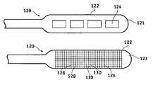
- FIGS. 16 and 17are top and bottom views respectively, of the inventive electrode assembly.
- the distal region 120 of an implantable leadincludes a paddle-shaped lead body 122 (typically a flexible polymer or other similar material) having a first surface 121 and a second opposite surface 123 .
- At least one therapy electrode 124is positioned on surface 121 . While four such electrodes are shown in FIG. 16 , it is to be understood that the number of electrodes may vary with different therapy regimens.
- each electrode 124is internally electrically coupled to a conductive filer (e.g. 98 in FIGS. 12 and 13 ) which is in turn electrically coupled to a pulse generator (e.g. neurostimulator 102 in FIG. 14 ) for the purpose of conducting stimulation pulses to a patient.
- a conductive filere.g. 98 in FIGS. 12 and 13
- a pulse generatore.g. neurostimulator 102 in FIG. 14
- the paddle electrode assembly shown in FIGS. 16 and 17is configured to safely dissipate the energy created during an MRI scan by directing the induced currents to a floating electrode having a large surface.
- a conductive mesh plate 126comprises a plurality of longitudinal conductors 128 that are intersected by a plurality of transverse conductors 130 .
- Conductive mesh 126may be imbedded in the underside of paddle 122 as indicated in FIG. 17 and as will be more fully described below.
- high-pass or band-pass filtersmay be coupled between electrodes 124 and mesh 126 to ensure that current does not flow to mesh plate 126 at pulse stimulation frequencies.
- Such high-pass filtersmay be simple capacitors 132 as shown in FIG. 18 .
- Conductive mesh plate 126may be configured to cover the entire posterior side of paddle electrode 122 in order to achieve the desired surface area.
- electrodes 124may have a surface area of approximately 10 square millimeters
- conductive mesh plate 126may have a surface area of approximately 120 square millimeters. This configuration of mesh plate 126 provides for easy retention within the lead body 122 while still providing sufficient surface area in contact with the patient's tissue.
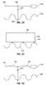
- mesh plate 126may have a wavy configuration such as is shown in FIG. 19 to enable a portion of the mesh plate indicated at 134 to be captured in body 122 while the remainder of mesh plate 126 is exposed for contact with a patient's tissue.
- FIG. 20illustrates an exemplary embodiment of the present invention wherein the high-pass filter represented by capacitor 132 is coupled between mesh plate 126 and conductive filer 136 at a location proximal of electrode 124 .
- the high-pass filter represented by capacitor 132is coupled between mesh plate 126 and conductive filer 136 at a location proximal of electrode 124 .
- induced RF energywill be diverted through capacitor 132 at high frequencies (MRI frequencies) to mesh plate 126 prior to reaching electrode 124 .
- Capacitor 132may be of the ceramic variety and therefore capable of withstanding the environment within a patient's body.
- the leadscould be crimped, cross-welded, or bonded using a conductive adhesive to filer 136 and mesh plate 126 as is shown at 138 .
- capacitors in the range of 200 pF to 47,000 pF, preferably a 1000 pFmay be utilized to create a high-pass filter that acts with a high impedance at DC and stimulation frequencies and low impedance at MRI frequencies.
- FIG. 21illustrates another embodiment of the inventive lead electrode assembly.
- a dielectric material 140e.g. tantalum oxide
- An additional capacitor plate 142may be provided between dielectric layer 140 and mesh plate 126 if more capacitance is needed or to provide a good connection mechanism to floating plate 126 .
- FIG. 22is a schematic diagram of yet another embodiment of the inventive lead electrode assembly. As can be seen, the arrangement shown in FIG. 22 is substantially the same as that shown in FIG. 20 except that an inductor 144 has been inserted just proximal of electrode 124 . While the impedance of capacitor 132 is low at MRI frequencies, in contrast the impedance of inductor 144 is high at MRI frequencies. Thus, induced currents flowing in filer 136 toward electrode 124 are further encouraged toward floating electrode 126 thus restricting the amount of current reaching stimulation electrode 124 . If desired, an additional inductor 145 may be utilized as a replacement for or in addition to inductor 144 . Inductor 145 is positioned between filer 136 and capacitor 132 and reflects at least a portion of the induced RF energy in a proximal direction along filer 136 at high frequency.
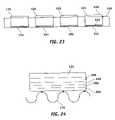
- FIG. 23illustrates yet another embodiment of the present invention.
- the stimulation electrodes 125themselves also act as a floating electrode to provide capacitive coupling to the patient's body tissue or fluid.
- each stimulation electrode 124comprises a stimulation surface 150 for transmitting a desired stimulation therapy to the patient and an opposite surface 152 that is covered to coated with a thin, dielectric or insulative layer 154 (e.g. a non-conductive polymer such as silicone, tantalum oxide, etc.), thus capacitively coupling electrode 125 to the patient's body tissue or fluid.
- a thin, dielectric or insulative layer 154e.g. a non-conductive polymer such as silicone, tantalum oxide, etc.
- the amount of capacitancemay be varied by selecting the thickness and/or material characteristics of layer 154 in accordance with known techniques.
- alternating layers of conducting layers 156e.g. platinum, stainless steel, MP35n, etc.
- dielectric layers 158e.g. silicone
- mesh 126is optional if the last layer 160 is conductive and is configured to be placed in contact with the patient's body tissue or fluid.
Landscapes
- Health & Medical Sciences (AREA)
- General Health & Medical Sciences (AREA)
- Animal Behavior & Ethology (AREA)
- Veterinary Medicine (AREA)
- Public Health (AREA)
- Biomedical Technology (AREA)
- Engineering & Computer Science (AREA)
- Nuclear Medicine, Radiotherapy & Molecular Imaging (AREA)
- Life Sciences & Earth Sciences (AREA)
- Radiology & Medical Imaging (AREA)
- Neurosurgery (AREA)
- Heart & Thoracic Surgery (AREA)
- Neurology (AREA)
- Cardiology (AREA)
- Psychology (AREA)
- Orthopedic Medicine & Surgery (AREA)
- Electrotherapy Devices (AREA)
Abstract
Description
Z=1/jωC Equation (1)
The maximum stimulation frequency is in the order of 1000 Hz, which is approximately four orders of magnitude lower than the lowest MRI frequency of approximately 43 MHz at 1.0 Tesla. Thus, it can be determined that capacitors in the range of 200 pF to 47,000 pF, preferably a 1000 pF, may be utilized to create a high-pass filter that acts with a high impedance at DC and stimulation frequencies and low impedance at MRI frequencies.
Claims (61)
Priority Applications (5)
| Application Number | Priority Date | Filing Date | Title |
|---|---|---|---|
| US10/981,092US7174219B2 (en) | 2004-03-30 | 2004-11-03 | Lead electrode for use in an MRI-safe implantable medical device |
| DE602004028519TDE602004028519D1 (en) | 2004-03-30 | 2004-12-10 | ELECTRODE FOR USE IN AN MRI-SAFE IMPLANTABLE MEDICINE PRODUCT |
| AT04813513TATE476220T1 (en) | 2004-03-30 | 2004-12-10 | ELECTRODE FOR USE IN AN MRI SAFE IMPLANTABLE MEDICAL DEVICE |
| PCT/US2004/041201WO2005102446A1 (en) | 2004-03-30 | 2004-12-10 | Lead electrode for use in an mri-safe implantable medical device |
| EP04813513AEP1742701B1 (en) | 2004-03-30 | 2004-12-10 | Electrode for use in an mri-safe implantable medical device |
Applications Claiming Priority (2)
| Application Number | Priority Date | Filing Date | Title |
|---|---|---|---|
| US55799104P | 2004-03-30 | 2004-03-30 | |
| US10/981,092US7174219B2 (en) | 2004-03-30 | 2004-11-03 | Lead electrode for use in an MRI-safe implantable medical device |
Publications (2)
| Publication Number | Publication Date |
|---|---|
| US20050222647A1 US20050222647A1 (en) | 2005-10-06 |
| US7174219B2true US7174219B2 (en) | 2007-02-06 |
Family
ID=35196752
Family Applications (1)
| Application Number | Title | Priority Date | Filing Date |
|---|---|---|---|
| US10/981,092Expired - LifetimeUS7174219B2 (en) | 2004-03-30 | 2004-11-03 | Lead electrode for use in an MRI-safe implantable medical device |
Country Status (2)
| Country | Link |
|---|---|
| US (1) | US7174219B2 (en) |
| WO (1) | WO2005102446A1 (en) |
Cited By (180)
| Publication number | Priority date | Publication date | Assignee | Title |
|---|---|---|---|---|
| US20050177199A1 (en)* | 2004-02-09 | 2005-08-11 | Cardiac Pacemakers, Inc. | PSA cable and connector for quadripolar lead terminal |
| US20050222659A1 (en)* | 2004-03-30 | 2005-10-06 | Medtronic, Inc. | Lead electrode for use in an MRI-safe implantable medical device |
| US20050222658A1 (en)* | 2004-03-30 | 2005-10-06 | Medtronic, Inc. | Lead electrode for use in an MRI-safe implantable medical device |
| US20050222657A1 (en)* | 2004-03-30 | 2005-10-06 | Wahlstrand Carl D | MRI-safe implantable lead |
| US20050222656A1 (en)* | 2004-03-30 | 2005-10-06 | Wahlstrand Carl D | MRI-safe implantable medical device |
| US20060200218A1 (en)* | 2005-02-01 | 2006-09-07 | Wahlstrand Carl D | Extensible implantable medical lead |
| US20060247714A1 (en)* | 2005-04-28 | 2006-11-02 | Taylor William J | Glass-to-metal feedthrough seals having improved durability particularly under AC or DC bias |
| US20060247748A1 (en)* | 2005-04-29 | 2006-11-02 | Medtronic, Inc. | Lead electrode for use in an MRI-safe implantable medical device |
| US20060258193A1 (en)* | 2005-05-12 | 2006-11-16 | Cardiac Pacemakers, Inc. | Lead terminal multi-tool |
| US20070244535A1 (en)* | 2006-04-18 | 2007-10-18 | Cyberonics, Inc. | Heat dissipation for a lead assembly |
| US20070260282A1 (en)* | 2003-09-12 | 2007-11-08 | Taylor William J | Feedthrough apparatus with noble metal-coated leads |
| US20080015641A1 (en)* | 2006-07-12 | 2008-01-17 | Cyberonics, Inc. | Implantable Medical Device Charge Balance Assessment |
| US20080114407A1 (en)* | 2006-11-13 | 2008-05-15 | Cardiac Pacemakers, Inc. | Reduction of av delay for treatment of cardiac disease |
| US20080114408A1 (en)* | 2006-11-13 | 2008-05-15 | Shuros Allan C | Method and device for simulated exercise |
| US20080183258A1 (en)* | 2007-01-26 | 2008-07-31 | Inman D Michael | Electrode assembly with fibers for a medical device |
| US20080195186A1 (en)* | 2007-02-14 | 2008-08-14 | Bernard Li | Continuous conductive materials for electromagnetic shielding |
| US20080249584A1 (en)* | 2007-04-05 | 2008-10-09 | Cardiac Pacemakers, Inc. | Method and device for cardiosympathetic inhibition |
| US20080269863A1 (en)* | 2007-04-25 | 2008-10-30 | Medtronic, Inc. | Lead or lead extension having a conductive body and conductive body contact |
| US20080269831A1 (en)* | 2007-04-25 | 2008-10-30 | Erickson John H | Implantable pulse generator comprising mri current limiting windings in header structure |
| US20090088812A1 (en)* | 2007-09-27 | 2009-04-02 | Wulfman David R | Implantable lead with electronics |
| US20090118610A1 (en)* | 2005-11-29 | 2009-05-07 | Karmarkar Parag V | Mri-guided localization and/or lead placement systems, related methods, devices and computer program products |
| US20090138058A1 (en)* | 2004-12-17 | 2009-05-28 | Cardiac Pacemakers, Inc. | Mri operation modes for implantable medical devices |
| US20090149934A1 (en)* | 2007-12-06 | 2009-06-11 | Cardiac Pacemakers, Inc. | Implantable lead with shielding |
| US20090149909A1 (en)* | 2007-12-06 | 2009-06-11 | Masoud Ameri | Selectively connecting the tip electrode during therapy for mri shielding |
| US20090149933A1 (en)* | 2007-12-06 | 2009-06-11 | Cardiac Pacemakers, Inc. | Implantable lead having a variable coil conductor pitch |
| US20090149906A1 (en)* | 2007-12-06 | 2009-06-11 | Masoud Ameri | Method and apparatus for disconnecting the tip electrode during mri |
| US20090149920A1 (en)* | 2007-12-06 | 2009-06-11 | Yingbo Li | Leads with high surface resistance |
| US20090163974A1 (en)* | 2003-09-12 | 2009-06-25 | Medtronic, Inc. | Feedthrough apparatus with noble metal-coated leads |
| US20090179716A1 (en)* | 2008-01-09 | 2009-07-16 | Anaren, Inc. | RF Filter Device |
| US20090204171A1 (en)* | 2008-02-11 | 2009-08-13 | Masoud Ameri | Mri shielding in electrodes using ac pacing |
| US20090203983A1 (en)* | 2008-02-08 | 2009-08-13 | Intelect Medical, Inc. | Multi-functional burr hole assembly |
| US20090204192A1 (en)* | 2008-02-11 | 2009-08-13 | Intelect Medical, Inc. | Directional electrode devices with locating features |
| US20090204182A1 (en)* | 2008-02-11 | 2009-08-13 | Masoud Ameri | Magnetic core flux canceling of ferrites in mri |
| US20090270956A1 (en)* | 2008-04-25 | 2009-10-29 | Pacesetter, Inc. | Implantable medical lead configured for improved mri safety |
| US20100001387A1 (en)* | 2007-03-23 | 2010-01-07 | Fujitsu Limited | Electronic device, electronic apparatus mounted with electronic device, article equipped with electronic device and method of producing electronic device |
| US20100010602A1 (en)* | 2006-11-30 | 2010-01-14 | Wedan Steven R | Rf rejecting lead |
| US20100016936A1 (en)* | 2001-04-13 | 2010-01-21 | Greatbatch Ltd. | Frequency selective passive component networks for implantable leads of active implantable medical devices utilizing an energy dissipating surface |
| US20100023000A1 (en)* | 2002-04-15 | 2010-01-28 | Greatbatch Ltd. | Frequency selective passive component networks for implantable leads of active implantable medical devices utilizing an energy dissipating surface |
| US20100030319A1 (en)* | 2008-07-31 | 2010-02-04 | Boston Scientific Scimed, Inc. | Coils for vascular implants or other uses |
| US20100049290A1 (en)* | 2008-08-25 | 2010-02-25 | Pacesetter, Inc. | Mri compatible lead |
| US20100076535A1 (en)* | 2008-09-25 | 2010-03-25 | Boston Scientific Neuromodulation Corporation | Leads with non-circular-shaped distal ends for brain stimulation systems and methods of making and using |
| US20100087892A1 (en)* | 2008-10-02 | 2010-04-08 | Stubbs Scott R | Implantable medical device responsive to mri induced capture threshold changes |
| US20100094364A1 (en)* | 2008-10-09 | 2010-04-15 | Boston Scientific Neuromodulation Corporation | Electrical stimulation leads having rf compatibility and methods of use and manufacture |
| US20100106215A1 (en)* | 2008-10-23 | 2010-04-29 | Stubbs Scott R | Systems and methods to detect implantable medical device configuaration changes affecting mri conditional safety |
| US20100114275A1 (en)* | 2008-10-30 | 2010-05-06 | Pacesetter, Inc. | Implantable medical lead including winding for improved mri safety |
| US7734354B1 (en) | 2006-08-04 | 2010-06-08 | Advanced Neuromodulation Systems, Inc. | Stimulation lead, stimulation system, and method for limiting MRI induced current in a stimulation lead |
| US20100160997A1 (en)* | 2001-04-13 | 2010-06-24 | Greatbatch Ltd. | Tuned energy balanced system for minimizing heating and/or to provide emi protection of implanted leads in a high power electromagnetic field environment |
| US20100168821A1 (en)* | 2001-04-13 | 2010-07-01 | Greatbatch Ltd. | Switched diverter circuits for minimizing heating of an implanted lead in a high power electromagnetic field environment |
| US20100191236A1 (en)* | 2001-04-13 | 2010-07-29 | Greatbatch Ltd. | Switched diverter circuits for minimizing heating of an implanted lead and/or providing emi protection in a high power electromagnetic field environment |
| US20100192374A1 (en)* | 2006-07-26 | 2010-08-05 | Cyberonics, Inc. | Multi-Electrode Assembly for an Implantable Medical Device |
| US20100211123A1 (en)* | 2009-02-19 | 2010-08-19 | Stubbs Scott R | Systems and methods for providing arrhythmia therapy in mri environments |
| US20100208397A1 (en)* | 2008-12-17 | 2010-08-19 | Greatbatch Ltd. | Switched safety protection circuit for an aimd system during exposure to high power electromagnetic fields |
| US20100234929A1 (en)* | 2009-03-12 | 2010-09-16 | Torsten Scheuermann | Thin profile conductor assembly for medical device leads |
| US20100312294A1 (en)* | 2008-04-30 | 2010-12-09 | Medtronic, Inc. | Medical device with self-healing material |
| US20100318164A1 (en)* | 2009-06-15 | 2010-12-16 | Pacesetter, Inc. | Mri compatible implantable lead with a distributed band stop filter |
| US20100324639A1 (en)* | 2001-04-13 | 2010-12-23 | Greatbatch Ltd. | Methodology and apparatus to terminate abandoned active implantable medical device leads |
| US20100331936A1 (en)* | 2009-06-26 | 2010-12-30 | Christopher Perrey | Medical device lead including a unifilar coil with improved torque transmission capacity and reduced mri heating |
| US20110029054A1 (en)* | 2009-07-31 | 2011-02-03 | Tranchina Benjamin A | Method for fabricating a stimulation lead to reduce mri heating and a stimulation lead for use within mri systems |
| US20110079423A1 (en)* | 2009-10-06 | 2011-04-07 | Pacesetter, Inc. | Mri compatible implantable lead |
| US20110082516A1 (en)* | 2008-06-03 | 2011-04-07 | Kast John E | Lead having radially spaced apart contacts to allow for adjustability |
| US20110087302A1 (en)* | 2009-10-09 | 2011-04-14 | Masoud Ameri | Mri compatible medical device lead including transmission line notch filters |
| US20110106231A1 (en)* | 2009-11-05 | 2011-05-05 | Pacesetter, Inc. | Mri-compatible implantable lead having a heat spreader and method of using same |
| US20110130803A1 (en)* | 2009-11-30 | 2011-06-02 | Boston Scientific Neuromodulation Corporation | Electrode array having concentric windowed cylinder electrodes and methods of making the same |
| US20110130816A1 (en)* | 2009-11-30 | 2011-06-02 | Boston Scientific Neuromodulation Corporation | Electrode array with electrodes having cutout portions and methods of making the same |
| US7962224B1 (en) | 2007-02-05 | 2011-06-14 | Advanced Neuromodulation Systems, Inc. | Stimulation lead, stimulation system, and method for limiting MRI-induced current in a stimulation lead |
| US20110144722A1 (en)* | 2009-12-10 | 2011-06-16 | Pacesetter, Inc. | Mri-compatible implantable lead with improved lc resonant component |
| US20110152990A1 (en)* | 2009-12-22 | 2011-06-23 | Pacesetter, Inc. | Mri compatible lead employing multiple miniature inductors |
| US20110160816A1 (en)* | 2009-12-30 | 2011-06-30 | Stubbs Scott R | Apparatus to selectively increase medical device lead inner conductor inductance |
| US20110160805A1 (en)* | 2009-12-30 | 2011-06-30 | Blair Erbstoeszer | Implantable electrical lead including a cooling assembly to dissipate mri induced electrode heat |
| US20110224765A1 (en)* | 2008-11-13 | 2011-09-15 | Koninklijke Philips Electronics N.V. | Spiraled wires in a deep-brain stimulator probe |
| US8032230B1 (en) | 2007-10-09 | 2011-10-04 | Advanced Neuromodulation Systems, Inc. | Stimulation lead, stimulation system, and method for limiting MRI induced current in a stimulation lead |
| US8095224B2 (en) | 2009-03-19 | 2012-01-10 | Greatbatch Ltd. | EMI shielded conduit assembly for an active implantable medical device |
| US8103360B2 (en) | 2008-05-09 | 2012-01-24 | Foster Arthur J | Medical lead coil conductor with spacer element |
| US8160717B2 (en) | 2008-02-19 | 2012-04-17 | Cardiac Pacemakers, Inc. | Model reference identification and cancellation of magnetically-induced voltages in a gradient magnetic field |
| DE102011009861A1 (en) | 2011-01-31 | 2012-08-02 | Heraeus Precious Metals Gmbh & Co. Kg | Process for the preparation of a cermet-containing feedthrough |
| DE102011009855A1 (en) | 2011-01-31 | 2012-08-02 | Heraeus Precious Metals Gmbh & Co. Kg | Ceramic bushing with inductive filter |
| DE102011009867A1 (en) | 2011-01-31 | 2012-08-02 | Heraeus Precious Metals Gmbh & Co. Kg | Ceramic bushing for a medically implantable device |
| DE102011009866A1 (en) | 2011-01-31 | 2012-08-02 | Heraeus Precious Metals Gmbh & Co. Kg | Directly applied electrical feedthrough |
| DE102011009859A1 (en) | 2011-01-31 | 2012-08-02 | Heraeus Precious Metals Gmbh & Co. Kg | Ceramic bushing with filter |
| DE102011009862A1 (en) | 2011-01-31 | 2012-08-02 | Heraeus Precious Metals Gmbh & Co. Kg | Cermet-containing bushing with holding element for a medically implantable device |
| DE102011009865A1 (en) | 2011-01-31 | 2012-08-02 | Heraeus Precious Metals Gmbh & Co. Kg | Headboard for a medically implantable device |
| DE102011009857A1 (en) | 2011-01-31 | 2012-08-02 | Heraeus Precious Metals Gmbh & Co. Kg | Electrical feedthrough with a cermet-like connector for an active implantable medical device |
| DE102011009863A1 (en) | 2011-01-31 | 2012-08-02 | Heraeus Precious Metals Gmbh & Co. Kg | Ceramic bushing with conductive elements of high conductivity |
| DE102011009856A1 (en) | 2011-01-31 | 2012-08-02 | W.C. Heraeus Gmbh | An electrical feedthrough and method of making a lead-containing feedthrough for a medically implantable device |
| DE102011009860A1 (en) | 2011-01-31 | 2012-08-02 | Heraeus Precious Metals Gmbh & Co. Kg | Implantable device with integrated ceramic bushing |
| DE102011009858A1 (en) | 2011-01-31 | 2012-08-02 | Heraeus Precious Metals Gmbh & Co. Kg | Cermet-containing bushing for a medically implantable device with a bonding layer |
| US8244346B2 (en) | 2008-02-06 | 2012-08-14 | Cardiac Pacemakers, Inc. | Lead with MRI compatible design features |
| US8315689B2 (en) | 2007-09-24 | 2012-11-20 | MRI Interventions, Inc. | MRI surgical systems for real-time visualizations using MRI image data and predefined data of surgical tools |
| US8335572B2 (en) | 2009-10-08 | 2012-12-18 | Cardiac Pacemakers, Inc. | Medical device lead including a flared conductive coil |
| US8380324B2 (en) | 2009-08-20 | 2013-02-19 | Boston Scientific Neuromodulation Corporation | Systems and methods for altering one or more RF-response properties of electrical stimulation systems |
| US8391994B2 (en) | 2009-12-31 | 2013-03-05 | Cardiac Pacemakers, Inc. | MRI conditionally safe lead with low-profile multi-layer conductor for longitudinal expansion |
| US8478428B2 (en) | 2010-04-23 | 2013-07-02 | Cyberonics, Inc. | Helical electrode for nerve stimulation |
| US8521307B2 (en) | 2009-03-31 | 2013-08-27 | St. Jude Medical Ab | Implantable MRI compatible medical lead |
| US8565874B2 (en) | 2009-12-08 | 2013-10-22 | Cardiac Pacemakers, Inc. | Implantable medical device with automatic tachycardia detection and control in MRI environments |
| US8630718B2 (en) | 2010-11-18 | 2014-01-14 | Cardiac Pacemakers, Inc. | Insulative structure for MRI compatible leads |
| US8666512B2 (en) | 2011-11-04 | 2014-03-04 | Cardiac Pacemakers, Inc. | Implantable medical device lead including inner coil reverse-wound relative to shocking coil |
| US8761899B2 (en) | 2009-03-04 | 2014-06-24 | Imricor Medical Systems, Inc. | MRI compatible conductive wires |
| US8761900B2 (en) | 2009-03-04 | 2014-06-24 | Imricor Medical Systems, Inc. | MRI compatible electrode circuit |
| US8774937B2 (en) | 2009-12-01 | 2014-07-08 | Ecole Polytechnique Federale De Lausanne | Microfabricated surface neurostimulation device and methods of making and using the same |
| US8788064B2 (en) | 2008-11-12 | 2014-07-22 | Ecole Polytechnique Federale De Lausanne | Microfabricated neurostimulation device |
| US8788042B2 (en) | 2008-07-30 | 2014-07-22 | Ecole Polytechnique Federale De Lausanne (Epfl) | Apparatus and method for optimized stimulation of a neurological target |
| US8798767B2 (en) | 2009-12-31 | 2014-08-05 | Cardiac Pacemakers, Inc. | MRI conditionally safe lead with multi-layer conductor |
| US8805540B2 (en) | 2009-03-04 | 2014-08-12 | Imricor Medical Systems, Inc. | MRI compatible cable |
| US8805519B2 (en) | 2010-09-30 | 2014-08-12 | Nevro Corporation | Systems and methods for detecting intrathecal penetration |
| US8825179B2 (en) | 2012-04-20 | 2014-09-02 | Cardiac Pacemakers, Inc. | Implantable medical device lead including a unifilar coiled cable |
| US8825181B2 (en) | 2010-08-30 | 2014-09-02 | Cardiac Pacemakers, Inc. | Lead conductor with pitch and torque control for MRI conditionally safe use |
| US8831743B2 (en) | 2009-03-04 | 2014-09-09 | Imricor Medical Systems, Inc. | MRI compatible electrode circuit |
| US8855788B2 (en) | 2009-03-04 | 2014-10-07 | Imricor Medical Systems, Inc. | MRI compatible electrode circuit |
| US8868203B2 (en) | 2007-10-26 | 2014-10-21 | Cyberonics, Inc. | Dynamic lead condition detection for an implantable medical device |
| US8868208B2 (en) | 2012-10-23 | 2014-10-21 | Medtronic, Inc. | MR-compatible implantable medical lead |
| US8882763B2 (en) | 2010-01-12 | 2014-11-11 | Greatbatch Ltd. | Patient attached bonding strap for energy dissipation from a probe or a catheter during magnetic resonance imaging |
| US8903505B2 (en) | 2006-06-08 | 2014-12-02 | Greatbatch Ltd. | Implantable lead bandstop filter employing an inductive coil with parasitic capacitance to enhance MRI compatibility of active medical devices |
| US8942798B2 (en) | 2007-10-26 | 2015-01-27 | Cyberonics, Inc. | Alternative operation mode for an implantable medical device based upon lead condition |
| US8954168B2 (en) | 2012-06-01 | 2015-02-10 | Cardiac Pacemakers, Inc. | Implantable device lead including a distal electrode assembly with a coiled component |
| US8954165B2 (en) | 2012-01-25 | 2015-02-10 | Nevro Corporation | Lead anchors and associated systems and methods |
| US8958889B2 (en) | 2012-08-31 | 2015-02-17 | Cardiac Pacemakers, Inc. | MRI compatible lead coil |
| US8965482B2 (en) | 2010-09-30 | 2015-02-24 | Nevro Corporation | Systems and methods for positioning implanted devices in a patient |
| US8983623B2 (en) | 2012-10-18 | 2015-03-17 | Cardiac Pacemakers, Inc. | Inductive element for providing MRI compatibility in an implantable medical device lead |
| US8989840B2 (en) | 2004-03-30 | 2015-03-24 | Medtronic, Inc. | Lead electrode for use in an MRI-safe implantable medical device |
| US9014815B2 (en) | 2009-11-19 | 2015-04-21 | Medtronic, Inc. | Electrode assembly in a medical electrical lead |
| US9084882B1 (en) | 2014-02-26 | 2015-07-21 | Advanced Neuromodulation Systems, Inc. | Leads for neurostimulation and methods of assembling same |
| US9108066B2 (en) | 2008-03-20 | 2015-08-18 | Greatbatch Ltd. | Low impedance oxide resistant grounded capacitor for an AIMD |
| US9126031B2 (en) | 2010-04-30 | 2015-09-08 | Medtronic, Inc. | Medical electrical lead with conductive sleeve head |
| US9186499B2 (en) | 2009-04-30 | 2015-11-17 | Medtronic, Inc. | Grounding of a shield within an implantable medical lead |
| US9254380B2 (en) | 2009-10-19 | 2016-02-09 | Cardiac Pacemakers, Inc. | MRI compatible tachycardia lead |
| US9265935B2 (en) | 2013-06-28 | 2016-02-23 | Nevro Corporation | Neurological stimulation lead anchors and associated systems and methods |
| US9295828B2 (en) | 2001-04-13 | 2016-03-29 | Greatbatch Ltd. | Self-resonant inductor wound portion of an implantable lead for enhanced MRI compatibility of active implantable medical devices |
| US9370311B2 (en) | 2012-08-17 | 2016-06-21 | Medtronic Ablation Frontiers Llc | Electrophysiology catheter design |
| US9403023B2 (en) | 2013-08-07 | 2016-08-02 | Heraeus Deutschland GmbH & Co. KG | Method of forming feedthrough with integrated brazeless ferrule |
| US9402996B2 (en) | 2014-02-11 | 2016-08-02 | Cardiac Pacemakers, Inc. | RF shield for an implantable lead |
| US9403020B2 (en) | 2008-11-04 | 2016-08-02 | Nevro Corporation | Modeling positions of implanted devices in a patient |
| US9403011B2 (en) | 2014-08-27 | 2016-08-02 | Aleva Neurotherapeutics | Leadless neurostimulator |
| US9431801B2 (en) | 2013-05-24 | 2016-08-30 | Heraeus Deutschland GmbH & Co. KG | Method of coupling a feedthrough assembly for an implantable medical device |
| US9427596B2 (en) | 2013-01-16 | 2016-08-30 | Greatbatch Ltd. | Low impedance oxide resistant grounded capacitor for an AIMD |
| US9463317B2 (en) | 2012-04-19 | 2016-10-11 | Medtronic, Inc. | Paired medical lead bodies with braided conductive shields having different physical parameter values |
| US9474894B2 (en) | 2014-08-27 | 2016-10-25 | Aleva Neurotherapeutics | Deep brain stimulation lead |
| US9478959B2 (en) | 2013-03-14 | 2016-10-25 | Heraeus Deutschland GmbH & Co. KG | Laser welding a feedthrough |
| US9504821B2 (en) | 2014-02-26 | 2016-11-29 | Cardiac Pacemakers, Inc. | Construction of an MRI-safe tachycardia lead |
| US9504841B2 (en) | 2013-12-12 | 2016-11-29 | Heraeus Deutschland GmbH & Co. KG | Direct integration of feedthrough to implantable medical device housing with ultrasonic welding |
| US9517341B2 (en) | 2005-04-29 | 2016-12-13 | Medtronic, Inc. | Lead electrode for use in an MRI-safe implantable medical device |
| US9549708B2 (en) | 2010-04-01 | 2017-01-24 | Ecole Polytechnique Federale De Lausanne | Device for interacting with neurological tissue and methods of making and using the same |
| US9610451B2 (en) | 2013-12-12 | 2017-04-04 | Heraeus Deutschland GmbH & Co. KG | Direct integration of feedthrough to implantable medical device housing using a gold alloy |
| US9610452B2 (en) | 2013-12-12 | 2017-04-04 | Heraeus Deutschland GmbH & Co. KG | Direct integration of feedthrough to implantable medical device housing by sintering |
| US9731119B2 (en) | 2008-03-12 | 2017-08-15 | Medtronic, Inc. | System and method for implantable medical device lead shielding |
| US9750944B2 (en) | 2009-12-30 | 2017-09-05 | Cardiac Pacemakers, Inc. | MRI-conditionally safe medical device lead |
| EP3228354A1 (en) | 2016-04-07 | 2017-10-11 | Heraeus Deutschland GmbH & Co. KG | Feedthrough with a cermet conductor and a method of connecting a wire to a feedthrough |
| US9802037B2 (en) | 2015-03-05 | 2017-10-31 | Bradley D. Vilims | Tension loop for a spinal cord stimulator |
| USRE46699E1 (en) | 2013-01-16 | 2018-02-06 | Greatbatch Ltd. | Low impedance oxide resistant grounded capacitor for an AIMD |
| US9925376B2 (en) | 2014-08-27 | 2018-03-27 | Aleva Neurotherapeutics | Treatment of autoimmune diseases with deep brain stimulation |
| US9931514B2 (en) | 2013-06-30 | 2018-04-03 | Greatbatch Ltd. | Low impedance oxide resistant grounded capacitor for an AIMD |
| US9943685B2 (en) | 2015-04-23 | 2018-04-17 | Cyberonics, Inc. | Lead engagement devices and methods for electrical stimulation and/or monitoring systems |
| US9993638B2 (en) | 2013-12-14 | 2018-06-12 | Medtronic, Inc. | Devices, systems and methods to reduce coupling of a shield and a conductor within an implantable medical lead |
| US10080889B2 (en) | 2009-03-19 | 2018-09-25 | Greatbatch Ltd. | Low inductance and low resistance hermetically sealed filtered feedthrough for an AIMD |
| US10092766B2 (en) | 2011-11-23 | 2018-10-09 | Heraeus Deutschland GmbH & Co. KG | Capacitor and method to manufacture the capacitor |
| US10155111B2 (en) | 2014-07-24 | 2018-12-18 | Medtronic, Inc. | Methods of shielding implantable medical leads and implantable medical lead extensions |
| US10232169B2 (en) | 2015-07-23 | 2019-03-19 | Boston Scientific Neuromodulation Corporation | Burr hole plugs for electrical stimulation systems and methods of making and using |
| US10279171B2 (en) | 2014-07-23 | 2019-05-07 | Medtronic, Inc. | Methods of shielding implantable medical leads and implantable medical lead extensions |
| US10350421B2 (en) | 2013-06-30 | 2019-07-16 | Greatbatch Ltd. | Metallurgically bonded gold pocket pad for grounding an EMI filter to a hermetic terminal for an active implantable medical device |
| US10398893B2 (en) | 2007-02-14 | 2019-09-03 | Medtronic, Inc. | Discontinuous conductive filler polymer-matrix composites for electromagnetic shielding |
| US10478618B2 (en) | 2015-03-05 | 2019-11-19 | Bradley D. Vilims | Adjustable length tension sleeve for electrical or thermal stimulation device |
| US10559409B2 (en) | 2017-01-06 | 2020-02-11 | Greatbatch Ltd. | Process for manufacturing a leadless feedthrough for an active implantable medical device |
| US10561837B2 (en) | 2011-03-01 | 2020-02-18 | Greatbatch Ltd. | Low equivalent series resistance RF filter for an active implantable medical device utilizing a ceramic reinforced metal composite filled via |
| US10589107B2 (en) | 2016-11-08 | 2020-03-17 | Greatbatch Ltd. | Circuit board mounted filtered feedthrough assembly having a composite conductive lead for an AIMD |
| US10905888B2 (en) | 2018-03-22 | 2021-02-02 | Greatbatch Ltd. | Electrical connection for an AIMD EMI filter utilizing an anisotropic conductive layer |
| US10905497B2 (en) | 2017-04-21 | 2021-02-02 | Clearpoint Neuro, Inc. | Surgical navigation systems |
| US10912945B2 (en) | 2018-03-22 | 2021-02-09 | Greatbatch Ltd. | Hermetic terminal for an active implantable medical device having a feedthrough capacitor partially overhanging a ferrule for high effective capacitance area |
| US10966620B2 (en) | 2014-05-16 | 2021-04-06 | Aleva Neurotherapeutics Sa | Device for interacting with neurological tissue and methods of making and using the same |
| US10980999B2 (en) | 2017-03-09 | 2021-04-20 | Nevro Corp. | Paddle leads and delivery tools, and associated systems and methods |
| US11013913B2 (en) | 2018-03-16 | 2021-05-25 | Boston Scientific Neuromodulation Corporation | Kits and methods for securing a burr hole plugs for stimulation systems |
| US11058870B2 (en) | 2018-03-09 | 2021-07-13 | Boston Scientific Neuromodulation Corporation | Burr hole plugs for electrical stimulation systems and methods of making and using |
| US11103716B2 (en) | 2017-11-13 | 2021-08-31 | Boston Scientific Neuromodulation Corporation | Systems and methods for making and using a low-profile control module for an electrical stimulation system |
| US11198014B2 (en) | 2011-03-01 | 2021-12-14 | Greatbatch Ltd. | Hermetically sealed filtered feedthrough assembly having a capacitor with an oxide resistant electrical connection to an active implantable medical device housing |
| US11266830B2 (en) | 2018-03-02 | 2022-03-08 | Aleva Neurotherapeutics | Neurostimulation device |
| US11311718B2 (en) | 2014-05-16 | 2022-04-26 | Aleva Neurotherapeutics Sa | Device for interacting with neurological tissue and methods of making and using the same |
| US11420045B2 (en) | 2018-03-29 | 2022-08-23 | Nevro Corp. | Leads having sidewall openings, and associated systems and methods |
| US11497914B2 (en) | 2018-01-16 | 2022-11-15 | Boston Scientific Neuromodulation Corporation | Systems and methods for making and using an electrical stimulation system with a case-neutral battery |
| US11672976B2 (en) | 2019-10-10 | 2023-06-13 | Saluda Medical Pty Limited | Lead for an active implantable medical device with decoy |
| US11701519B2 (en) | 2020-02-21 | 2023-07-18 | Heraeus Medical Components Llc | Ferrule with strain relief spacer for implantable medical device |
| EP4302819A1 (en) | 2022-07-07 | 2024-01-10 | BIOTRONIK SE & Co. KG | A paddle lead |
| US11894163B2 (en) | 2020-02-21 | 2024-02-06 | Heraeus Medical Components Llc | Ferrule for non-planar medical device housing |
Families Citing this family (111)
| Publication number | Priority date | Publication date | Assignee | Title |
|---|---|---|---|---|
| US8244370B2 (en)* | 2001-04-13 | 2012-08-14 | Greatbatch Ltd. | Band stop filter employing a capacitor and an inductor tank circuit to enhance MRI compatibility of active medical devices |
| US6949929B2 (en)* | 2003-06-24 | 2005-09-27 | Biophan Technologies, Inc. | Magnetic resonance imaging interference immune device |
| US20070168005A1 (en)* | 2001-02-20 | 2007-07-19 | Biophan Technologies, Inc. | Medical device with an electrically conductive anti-antenna member |
| US20050288753A1 (en)* | 2003-08-25 | 2005-12-29 | Biophan Technologies, Inc. | Medical device with an electrically conductive anti-antenna member |
| US20050283214A1 (en)* | 2003-08-25 | 2005-12-22 | Biophan Technologies, Inc. | Medical device with an electrically conductive anti-antenna member |
| US20050283167A1 (en)* | 2003-08-25 | 2005-12-22 | Biophan Technologies, Inc. | Medical device with an electrically conductive anti-antenna member |
| US8219208B2 (en)* | 2001-04-13 | 2012-07-10 | Greatbatch Ltd. | Frequency selective passive component networks for active implantable medical devices utilizing an energy dissipating surface |
| US8600519B2 (en) | 2001-04-13 | 2013-12-03 | Greatbatch Ltd. | Transient voltage/current protection system for electronic circuits associated with implanted leads |
| US20040199069A1 (en)* | 2003-04-02 | 2004-10-07 | Connelly Patrick R. | Device and method for preventing magnetic resonance imaging induced damage |
| US7839146B2 (en) | 2003-06-24 | 2010-11-23 | Medtronic, Inc. | Magnetic resonance imaging interference immune device |
| US7388378B2 (en)* | 2003-06-24 | 2008-06-17 | Medtronic, Inc. | Magnetic resonance imaging interference immune device |
| US20050288756A1 (en)* | 2003-08-25 | 2005-12-29 | Biophan Technologies, Inc. | Medical device with an electrically conductive anti-antenna member |
| US20050288755A1 (en)* | 2003-08-25 | 2005-12-29 | Biophan Technologies, Inc. | Medical device with an electrically conductive anti-antenna member |
| US20050288751A1 (en)* | 2003-08-25 | 2005-12-29 | Biophan Technologies, Inc. | Medical device with an electrically conductive anti-antenna member |
| US20050288757A1 (en)* | 2003-08-25 | 2005-12-29 | Biophan Technologies, Inc. | Medical device with an electrically conductive anti-antenna member |
| US20050288754A1 (en)* | 2003-08-25 | 2005-12-29 | Biophan Technologies, Inc. | Medical device with an electrically conductive anti-antenna member |
| US8868212B2 (en) | 2003-08-25 | 2014-10-21 | Medtronic, Inc. | Medical device with an electrically conductive anti-antenna member |
| US20050049482A1 (en)* | 2003-08-25 | 2005-03-03 | Biophan Technologies, Inc. | Electromagnetic radiation transparent device and method of making thereof |
| WO2006023700A2 (en)* | 2004-08-20 | 2006-03-02 | Biophan Technologies, Inc. | Magnetic resonance imaging interference immune device |
| US20120277839A1 (en) | 2004-09-08 | 2012-11-01 | Kramer Jeffery M | Selective stimulation to modulate the sympathetic nervous system |
| US9205261B2 (en) | 2004-09-08 | 2015-12-08 | The Board Of Trustees Of The Leland Stanford Junior University | Neurostimulation methods and systems |
| US7337005B2 (en) | 2004-09-08 | 2008-02-26 | Spinal Modulations, Inc. | Methods for stimulating a nerve root ganglion |
| US8048080B2 (en) | 2004-10-15 | 2011-11-01 | Baxano, Inc. | Flexible tissue rasp |
| US8613745B2 (en) | 2004-10-15 | 2013-12-24 | Baxano Surgical, Inc. | Methods, systems and devices for carpal tunnel release |
| JP5243034B2 (en) | 2004-10-15 | 2013-07-24 | バクサノ,インク. | Tissue removal device |
| US8430881B2 (en) | 2004-10-15 | 2013-04-30 | Baxano, Inc. | Mechanical tissue modification devices and methods |
| US20110190772A1 (en) | 2004-10-15 | 2011-08-04 | Vahid Saadat | Powered tissue modification devices and methods |
| US7857813B2 (en) | 2006-08-29 | 2010-12-28 | Baxano, Inc. | Tissue access guidewire system and method |
| US8221397B2 (en) | 2004-10-15 | 2012-07-17 | Baxano, Inc. | Devices and methods for tissue modification |
| US9101386B2 (en) | 2004-10-15 | 2015-08-11 | Amendia, Inc. | Devices and methods for treating tissue |
| US9247952B2 (en) | 2004-10-15 | 2016-02-02 | Amendia, Inc. | Devices and methods for tissue access |
| US7578819B2 (en)* | 2005-05-16 | 2009-08-25 | Baxano, Inc. | Spinal access and neural localization |
| US20100331883A1 (en) | 2004-10-15 | 2010-12-30 | Schmitz Gregory P | Access and tissue modification systems and methods |
| US20070021667A1 (en)* | 2005-05-19 | 2007-01-25 | Biophan Technologies, Inc. | Electromagnetic resonant circuit sleeve for implantable medical device |
| US7801625B2 (en)* | 2005-05-27 | 2010-09-21 | Medtronic, Inc. | Electromagnetic interference immune pacing/defibrillation lead |
| US20060271144A1 (en)* | 2005-05-27 | 2006-11-30 | Biophan Technologies, Inc. | Electromagnetic interference immune pacing/defibrillation lead |
| US20060271142A1 (en)* | 2005-05-27 | 2006-11-30 | Biophan Technologies, Inc. | Electromagnetic interference immune pacing/defibrillation lead |
| US7529590B2 (en)* | 2005-05-27 | 2009-05-05 | Medtronic, Inc. | Electromagnetic interference immune pacing/defibrillation lead |
| US7539546B2 (en)* | 2005-05-27 | 2009-05-26 | Medtronic, Inc. | Electromagnetic interference immune pacing/defibrillation lead |
| US7539545B2 (en)* | 2005-05-27 | 2009-05-26 | Medtronic, Inc. | Electromagnetic interference immune pacing/defibrillation lead |
| US20060271139A1 (en)* | 2005-05-27 | 2006-11-30 | Biophan Technologies, Inc. | Electromagnetic interference immune pacing/defibrillation lead |
| US7555350B2 (en)* | 2005-05-27 | 2009-06-30 | Medtronic, Inc. | Electromagnetic interference immune pacing/defibrillation lead |
| US7551966B2 (en)* | 2005-05-27 | 2009-06-23 | Medtronic, Inc. | Electromagnetic interference immune pacing/defibrillation lead |
| US7529591B2 (en)* | 2005-05-27 | 2009-05-05 | Medtronic, Inc. | Electromagnetic interference immune pacing/defibrillation lead |
| WO2007042999A2 (en) | 2005-10-07 | 2007-04-19 | Neuronexus Technologies | Modular multichannel microelectrode array and methods of making same |
| US8062298B2 (en) | 2005-10-15 | 2011-11-22 | Baxano, Inc. | Flexible tissue removal devices and methods |
| US8366712B2 (en) | 2005-10-15 | 2013-02-05 | Baxano, Inc. | Multiple pathways for spinal nerve root decompression from a single access point |
| CA2623453C (en) | 2005-10-21 | 2016-02-09 | Surgi-Vision, Inc. | Mri-safe high impedance lead systems and related methods |
| US8255054B2 (en)* | 2005-11-04 | 2012-08-28 | Kenergy, Inc. | MRI compatible implanted electronic medical device |
| US8233985B2 (en)* | 2005-11-04 | 2012-07-31 | Kenergy, Inc. | MRI compatible implanted electronic medical device with power and data communication capability |
| US7564674B2 (en)* | 2005-12-12 | 2009-07-21 | Greatbatch Ltd. | Feedthrough filter capacitor assemblies having low cost terminal pins |
| US7702387B2 (en)* | 2006-06-08 | 2010-04-20 | Greatbatch Ltd. | Tank filters adaptable for placement with a guide wire, in series with the lead wires or circuits of active medical devices to enhance MRI compatibility |
| US9020610B2 (en) | 2006-06-23 | 2015-04-28 | Medtronic, Inc. | Electrode system with shunt electrode |
| US20130226267A9 (en)* | 2006-08-21 | 2013-08-29 | Marom Bikson | Method to reduce heating at implantable medical devices including neuroprosthetic devices |
| JP5414531B2 (en) | 2006-12-06 | 2014-02-12 | スパイナル・モデュレーション・インコーポレイテッド | Delivery device and systems and methods for stimulating neural tissue at multiple spinal levels |
| CA2671250A1 (en) | 2006-12-06 | 2008-06-12 | Spinal Modulation, Inc. | Hard tissue anchors and delivery devices |
| US9314618B2 (en) | 2006-12-06 | 2016-04-19 | Spinal Modulation, Inc. | Implantable flexible circuit leads and methods of use |
| CA2671575A1 (en)* | 2006-12-06 | 2008-06-12 | Spinal Modulation, Inc. | Grouped leads for spinal stimulation |
| WO2008070808A2 (en)* | 2006-12-06 | 2008-06-12 | Spinal Modulation, Inc. | Expandable stimulation leads and methods of use |
| US8768486B2 (en) | 2006-12-11 | 2014-07-01 | Medtronic, Inc. | Medical leads with frequency independent magnetic resonance imaging protection |
| US7991483B1 (en)* | 2006-12-21 | 2011-08-02 | Boston Scientific Neuromodulation Corporation | Implantable electrodes containing polyoxometalate anions and methods of manufacture and use |
| JP5562648B2 (en)* | 2007-01-29 | 2014-07-30 | スパイナル・モデュレーション・インコーポレイテッド | Non-stitched top retaining mechanism |
| US8731673B2 (en) | 2007-02-26 | 2014-05-20 | Sapiens Steering Brain Stimulation B.V. | Neural interface system |
| US8219207B2 (en)* | 2007-03-08 | 2012-07-10 | Medtronic, Inc. | Thermal switch for implantable medical devices |
| US20080262585A1 (en)* | 2007-04-20 | 2008-10-23 | Medtronic, Inc. | Implantable medical electrical lead and connector assembly |
| US8175677B2 (en)* | 2007-06-07 | 2012-05-08 | MRI Interventions, Inc. | MRI-guided medical interventional systems and methods |
| US8121705B2 (en)* | 2007-06-27 | 2012-02-21 | Medtronic, Inc. | MRI-safe defibrillator electrodes |
| FR2918285A1 (en)* | 2007-07-03 | 2009-01-09 | Commissariat Energie Atomique | MULTI-ELECTRODES PROBE AND SYSTEM FOR DEEP ELECTRICAL NEUROSTIMULATION COMPRISING SUCH A PROBE |
| US8195272B2 (en) | 2007-09-24 | 2012-06-05 | MRI Interventions, Inc. | MRI-compatible patches and methods for using the same |
| CA2700523A1 (en)* | 2007-09-24 | 2009-04-02 | Surgivision, Inc. | Mri-guided medical interventional systems and methods |
| US8565894B2 (en)* | 2007-10-17 | 2013-10-22 | Neuronexus Technologies, Inc. | Three-dimensional system of electrode leads |
| WO2009052425A1 (en) | 2007-10-17 | 2009-04-23 | Neuronexus Technologies | Implantable device including a resorbable carrier |
| US8224417B2 (en)* | 2007-10-17 | 2012-07-17 | Neuronexus Technologies, Inc. | Guide tube for an implantable device system |
| WO2009067205A1 (en)* | 2007-11-21 | 2009-05-28 | Surgi-Vision, Inc. | Methods, systems and computer program products for positioning a guidance apparatus relative to a patient |
| US8192436B2 (en) | 2007-12-07 | 2012-06-05 | Baxano, Inc. | Tissue modification devices |
| US8498720B2 (en) | 2008-02-29 | 2013-07-30 | Neuronexus Technologies, Inc. | Implantable electrode and method of making the same |
| EP2280757B1 (en)* | 2008-04-17 | 2017-07-12 | Medtronic, Inc. | Extensible implantable medical lead with braided conductors |
| US9192758B2 (en)* | 2008-04-17 | 2015-11-24 | Medtronic, Inc. | Extensible implantable medical lead with sigmoidal conductors |
| WO2009128967A1 (en)* | 2008-04-17 | 2009-10-22 | Medtronic, Inc. | Extensible implantable medical lead with co-axial conductor coils |
| US9314253B2 (en) | 2008-07-01 | 2016-04-19 | Amendia, Inc. | Tissue modification devices and methods |
| US8398641B2 (en) | 2008-07-01 | 2013-03-19 | Baxano, Inc. | Tissue modification devices and methods |
| US8409206B2 (en)* | 2008-07-01 | 2013-04-02 | Baxano, Inc. | Tissue modification devices and methods |
| AU2009271047B2 (en) | 2008-07-14 | 2014-04-17 | Baxano Surgical, Inc. | Tissue modification devices |
| EP2373378B1 (en) | 2008-10-27 | 2017-04-26 | Spinal Modulation Inc. | Selective stimulation systems and signal parameters for medical conditions |
| WO2010081167A1 (en)* | 2009-01-12 | 2010-07-15 | Greatbatch Ltd. | Switched diverter circuits for minimizing heating of an implanted lead in a high power electromagnetic field environment |
| EP2405823A4 (en)* | 2009-03-13 | 2012-07-04 | Baxano Inc | Flexible neural localization devices and methods |
| US8380318B2 (en)* | 2009-03-24 | 2013-02-19 | Spinal Modulation, Inc. | Pain management with stimulation subthreshold to paresthesia |
| WO2010132816A2 (en)* | 2009-05-15 | 2010-11-18 | Spinal Modulation, Inc. | Methods, systems and devices for neuromodulating spinal anatomy |
| US8394102B2 (en) | 2009-06-25 | 2013-03-12 | Baxano, Inc. | Surgical tools for treatment of spinal stenosis |
| US8332046B2 (en)* | 2009-10-16 | 2012-12-11 | Neuronexus Technologies, Inc. | Neural interface system |
| CA2798961A1 (en) | 2010-05-10 | 2011-11-17 | Spinal Modulation, Inc. | Methods, systems and devices for reducing migration |
| US9155861B2 (en) | 2010-09-20 | 2015-10-13 | Neuronexus Technologies, Inc. | Neural drug delivery system with fluidic threads |
| US8862246B2 (en)* | 2010-12-17 | 2014-10-14 | Biotronik Se & Co. Kg | Implantable device |
| CN103561811A (en) | 2011-02-02 | 2014-02-05 | 脊髓调制公司 | Devices, systems and methods for the targeted treatment of movement disorders |
| US9192446B2 (en) | 2012-09-05 | 2015-11-24 | MRI Interventions, Inc. | Trajectory guide frame for MRI-guided surgeries |
| WO2014164972A1 (en)* | 2013-03-15 | 2014-10-09 | Imricor Medical Systems, Inc. | Mri compatible handle and steerable sheath |
| US9731122B2 (en) | 2013-04-29 | 2017-08-15 | Rainbow Medical Ltd. | Electroosmotic tissue treatment |
| US9616221B2 (en) | 2015-07-08 | 2017-04-11 | Rainbow Medical Ltd. | Electrical treatment of Alzheimer's disease |
| US10898716B2 (en) | 2015-10-29 | 2021-01-26 | Rainbow Medical Ltd. | Electrical substance clearance from the brain |
| US11484706B2 (en) | 2015-12-29 | 2022-11-01 | Discure Technologies Ltd | Disc therapy |
| US9770591B2 (en) | 2015-12-29 | 2017-09-26 | Rainbow Medical Ltd. | Disc therapy |
| EP3329962B1 (en)* | 2016-11-15 | 2020-05-13 | Brainsgate Ltd. | Implant and delivery system for neural stimulator |
| US10569086B2 (en) | 2017-01-11 | 2020-02-25 | Rainbow Medical Ltd. | Electrical microglial cell activation |
| US10758722B2 (en) | 2017-05-03 | 2020-09-01 | Rainbow Medical Ltd. | Electrical treatment of Parkinson's disease |
| EP3765141A1 (en)* | 2018-03-14 | 2021-01-20 | Rainbow Medical Ltd. | Electrical substance clearance from the brain |
| US10881858B1 (en) | 2019-09-18 | 2021-01-05 | Rainbow Medical Ltd. | Electrical substance clearance from the brain |
| US11298530B1 (en) | 2021-05-03 | 2022-04-12 | Discure Technologies Ltd. | Synergistic therapies for intervertebral disc degeneration |
| US11344721B1 (en) | 2021-08-16 | 2022-05-31 | Rainbow Medical Ltd. | Cartilage treatment |
| US11413455B1 (en) | 2022-02-08 | 2022-08-16 | Rainbow Medical Ltd. | Electrical treatment of Alzheimer's disease |
| WO2024260653A1 (en) | 2023-06-22 | 2024-12-26 | Biotronik Se & Co. Kg | Medical electrode device for implantation into a patient and method for fabricating a medical electrode device |
| US12208267B1 (en) | 2024-04-19 | 2025-01-28 | Yossi Gross | Blood flow enhancement therapy system |
Citations (110)
| Publication number | Priority date | Publication date | Assignee | Title |
|---|---|---|---|---|
| US3788329A (en) | 1972-04-17 | 1974-01-29 | Medtronic Inc | Body implantable lead |
| US3915174A (en) | 1972-11-28 | 1975-10-28 | Thomas A Preston | Pacing apparatus and improved catheter |
| US4038990A (en) | 1975-11-19 | 1977-08-02 | Medtronic, Inc. | Cautery protection circuit for a heart pacemaker |
| US4220813A (en) | 1977-09-26 | 1980-09-02 | Medical Components Corp. | Terminal for medical instrument |
| US4280507A (en) | 1979-06-27 | 1981-07-28 | Hewlett-Packard Company | Patient cable with distributed resistance protection in conductors |
| US4320763A (en) | 1979-10-10 | 1982-03-23 | Telectronics Pty. Limited | Protection device for pacemaker implantees |
| US4628942A (en) | 1984-10-11 | 1986-12-16 | Case Western Reserve University | Asymmetric shielded two electrode cuff |
| US4726379A (en) | 1985-11-14 | 1988-02-23 | Cardiac Control Systems, Inc. | Cardiac pacer with switching circuit for isolation |
| US4852585A (en) | 1980-08-08 | 1989-08-01 | Darox Corporation | Tin-stannous chloride electrode element |
| US4920980A (en) | 1987-09-14 | 1990-05-01 | Cordis Corporation | Catheter with controllable tip |
| US4947866A (en) | 1988-02-16 | 1990-08-14 | Medtronic, Inc. | Medical electrical lead |
| US4951672A (en) | 1985-07-02 | 1990-08-28 | General Electric Company | Controlled impedance monitoring lead wires |
| US4991583A (en) | 1986-08-13 | 1991-02-12 | Siemens-Pacesetter, Inc. | Pacemaker having independently programmable electrode configuration for pacing and sensing and method for operation thereof |
| US5018523A (en) | 1990-04-23 | 1991-05-28 | Cardiac Pacemakers, Inc. | Apparatus for common mode stimulation with bipolar sensing |
| US5020544A (en) | 1989-11-01 | 1991-06-04 | Cardiac Pacemakers, Inc. | Low energy defibrillation electrode |
| US5036862A (en) | 1987-04-06 | 1991-08-06 | Cordis Corporation | Implantable, self-retaining lead |
| US5040544A (en) | 1988-02-16 | 1991-08-20 | Medtronic, Inc. | Medical electrical lead and method of manufacture |
| US5063932A (en) | 1989-10-03 | 1991-11-12 | Mieczyslaw Mirowski | Controlled discharge defibrillation electrode |
| US5197468A (en) | 1990-02-13 | 1993-03-30 | Proctor Paul W | Device for protecting an electronic prosthesis from adverse effects of RF and/or electrostatic energy |
| US5217010A (en)* | 1991-05-28 | 1993-06-08 | The Johns Hopkins University | Ecg amplifier and cardiac pacemaker for use during magnetic resonance imaging |
| US5314459A (en) | 1990-01-23 | 1994-05-24 | Cardiac Pacemakers, Inc. | Defibrillation electrode system having smooth current distribution with floating electrode |
| US5323776A (en) | 1992-10-15 | 1994-06-28 | Picker International, Inc. | MRI compatible pulse oximetry system |
| US5335657A (en) | 1991-05-03 | 1994-08-09 | Cyberonics, Inc. | Therapeutic treatment of sleep disorder by nerve stimulation |
| US5366496A (en) | 1993-04-01 | 1994-11-22 | Cardiac Pacemakers, Inc. | Subcutaneous shunted coil electrode |
| US5370644A (en) | 1988-11-25 | 1994-12-06 | Sensor Electronics, Inc. | Radiofrequency ablation catheter |
| US5417719A (en)* | 1993-08-25 | 1995-05-23 | Medtronic, Inc. | Method of using a spinal cord stimulation lead |
| JPH07255863A (en) | 1994-03-17 | 1995-10-09 | Kaageo P-Shingu Res Lab:Kk | Heart pacemaker |
| US5458629A (en) | 1994-02-18 | 1995-10-17 | Medtronic, Inc. | Implantable lead ring electrode and method of making |
| US5476496A (en) | 1993-06-01 | 1995-12-19 | Pacesetter Ab | Implantable medical electrode system having an indifferent electrode formed as a part of the electrode insulator sleeve |
| US5515848A (en) | 1991-10-22 | 1996-05-14 | Pi Medical Corporation | Implantable microelectrode |
| US5523578A (en) | 1995-03-22 | 1996-06-04 | Herskovic; Arnold | Electromagnetic radiation shielding arrangement and method for radiation therapy patients |
| US5591218A (en) | 1993-08-11 | 1997-01-07 | Ela Medical, S.A. | Current limiter for implantable electronic device lead |
| US5629622A (en) | 1995-07-11 | 1997-05-13 | Hewlett-Packard Company | Magnetic field sense system for the protection of connected electronic devices |
| US5649965A (en) | 1994-12-30 | 1997-07-22 | Ela Medical S.A. | Protection against electromagnetic perturbations of external origin for a active implantable device |
| US5683435A (en) | 1995-11-13 | 1997-11-04 | Pacesetter, Inc. | Implantable medical device having shielded and filtered feedthrough assembly and methods for making such assembly |
| WO1997041923A1 (en) | 1996-05-03 | 1997-11-13 | Sulzer Intermedics Inc. | Implantable cardiac cardioverter/defibrillator with emi suppression filter with independent ground |
| US5697958A (en) | 1995-06-07 | 1997-12-16 | Intermedics, Inc. | Electromagnetic noise detector for implantable medical devices |
| US5697909A (en) | 1992-01-07 | 1997-12-16 | Arthrocare Corporation | Methods and apparatus for surgical cutting |
| US5702437A (en) | 1996-04-10 | 1997-12-30 | Medtronic Inc. | Implantable lead with wires carried by body |
| US5722998A (en) | 1995-06-07 | 1998-03-03 | Intermedics, Inc. | Apparatus and method for the control of an implantable medical device |
| US5727552A (en) | 1996-01-11 | 1998-03-17 | Medtronic, Inc. | Catheter and electrical lead location system |
| US5751539A (en) | 1996-04-30 | 1998-05-12 | Maxwell Laboratories, Inc. | EMI filter for human implantable heart defibrillators and pacemakers |
| US5782241A (en) | 1993-04-22 | 1998-07-21 | O.D.A.M. Office De Distribution D'appareils Medicaux (Sa) | Sensor device for electrocardiogram |
| US5814076A (en) | 1996-02-09 | 1998-09-29 | Cardiac Control Systems, Inc. | Apparatus for improved cardiac pacing and sensing using extracardiac indifferent electrode configurations |
| US5827997A (en) | 1994-09-30 | 1998-10-27 | Chung; Deborah D. L. | Metal filaments for electromagnetic interference shielding |
| US5842966A (en) | 1990-05-04 | 1998-12-01 | Bio-Magnetic Therapy Systems, Inc. | Treatment of arthritis with magnetic field therapy |
| EP0713714A3 (en) | 1994-11-22 | 1999-01-27 | Ventritex, Inc. | Correlator based electromagnetic interference responsive control system useful in medical devices |
| WO1999019020A1 (en) | 1997-10-15 | 1999-04-22 | Minrad Inc. | Magnetically compatible peripheral nerve stimulator |
| US5905627A (en) | 1997-09-10 | 1999-05-18 | Maxwell Energy Products, Inc. | Internally grounded feedthrough filter capacitor |
| WO1999010035A3 (en) | 1997-08-22 | 1999-06-03 | Image Guided Neurologics Inc | Invasive medical device including an opposed solenoid rf coil for mri |
| WO1999060370A3 (en) | 1998-05-15 | 2000-02-03 | Robin Medical Inc | Method and apparatus for generating controlled torques |
| US6033408A (en) | 1996-07-30 | 2000-03-07 | Midas Rex, L.P. | Resecting tool for magnetic field environment |
| WO2000027279A1 (en) | 1998-11-10 | 2000-05-18 | Durousseau Donald R | fMRI COMPATIBLE ELECTRODE AND ELECTRODE PLACEMENT TECHNIQUES |
| US6101417A (en) | 1998-05-12 | 2000-08-08 | Pacesetter, Inc. | Implantable electrical device incorporating a magnetoresistive magnetic field sensor |
| US6198972B1 (en) | 1997-04-30 | 2001-03-06 | Medtronic, Inc. | Control of externally induced current in implantable medical devices |
| US6258071B1 (en) | 1995-08-31 | 2001-07-10 | Jocelyn Asher Simon Brookes | Magnetic resonance-compatible needle |
| US6348070B1 (en) | 1998-04-17 | 2002-02-19 | Med-El Elektromedizinische Gerate Ges.M.B.H | Magnetic-interference-free surgical prostheses |
| US20020032468A1 (en) | 1996-04-30 | 2002-03-14 | Hill Michael R.S. | Method and system for endotracheal/esophageal stimulation prior to and during a medical procedure |
| US20020038135A1 (en) | 2000-04-20 | 2002-03-28 | Connelly Patrick R. | MRI-resistant implantable device |
| US6424234B1 (en) | 1998-09-18 | 2002-07-23 | Greatbatch-Sierra, Inc. | Electromagnetic interference (emi) filter and process for providing electromagnetic compatibility of an electronic device while in the presence of an electromagnetic emitter operating at the same frequency |
| US20020116028A1 (en) | 2001-02-20 | 2002-08-22 | Wilson Greatbatch | MRI-compatible pacemaker with pulse carrying photonic catheter providing VOO functionality |
| US20020116034A1 (en) | 2001-02-20 | 2002-08-22 | Victor Miller | Controllable, wearable MRI-compatible pacemaker with power carrying photonic catheter and VOO functionality |
| US20020116033A1 (en) | 2001-02-20 | 2002-08-22 | Wilson Greatbatch | Controllable, wearable MRI-compatible cardiac pacemaker with pulse carrying photonic catheter and VOO functionality |
| US6471699B1 (en) | 1993-10-14 | 2002-10-29 | Ep Technologies, Inc. | Systems and methods for forming elongated lesion patterns in body tissue using straight or curvilinear electrode elements |
| US6488704B1 (en) | 2001-05-07 | 2002-12-03 | Biomed Solutions, Llc | Implantable particle measuring apparatus |
| US20020183740A1 (en) | 1992-08-12 | 2002-12-05 | Vidamed, Inc. | Medical probe device and method relationship to copending application |
| US20020188345A1 (en) | 2001-06-06 | 2002-12-12 | Pacetti Stephen Dirk | MRI compatible stent |
| US6494916B1 (en) | 2001-07-30 | 2002-12-17 | Biomed Solutions, Llc | Apparatus for replacing musculo-skeletal parts |
| US6501991B1 (en) | 2000-06-21 | 2002-12-31 | Medtronic, Inc. | Electrically-isolated multiple conductor lead body |
| US6503648B1 (en) | 2001-03-26 | 2003-01-07 | Biomed Solutions, Llc | Implantable fuel cell |
| EP1273922A1 (en) | 2001-07-06 | 2003-01-08 | Max-Planck-Gesellschaft zur Förderung der Wissenschaften e.V. | Methods and devices for measuring electrical currents |
| US20030009207A1 (en) | 2001-07-09 | 2003-01-09 | Paspa Paul M. | Implantable medical lead |
| US6506972B1 (en) | 2002-01-22 | 2003-01-14 | Nanoset, Llc | Magnetically shielded conductor |
| US20030014080A1 (en) | 2001-06-28 | 2003-01-16 | Baudino Michael D. | Low impedance implantable extension for a neurological electrical stimulator |
| US20030036776A1 (en) | 2000-04-20 | 2003-02-20 | Foster Thomas H. | MRI-compatible implantable device |
| US6529774B1 (en) | 2000-11-09 | 2003-03-04 | Neuropace, Inc. | Extradural leads, neurostimulator assemblies, and processes of using them for somatosensory and brain stimulation |
| US6538191B1 (en) | 2001-09-26 | 2003-03-25 | Biomed Solutions, Llc | Photocell with fluorescent conversion layer |
| US20030083726A1 (en) | 2001-10-31 | 2003-05-01 | Medtronic, Inc. | Method and apparatus for shunting induced currents in an electrical lead |
| US20030083723A1 (en) | 2001-10-31 | 2003-05-01 | Wilkinson Jeffrey D. | Apparatus and method for shunting induced currents in an electrical lead |
| US20030083570A1 (en) | 2001-10-31 | 2003-05-01 | Cho Yong Kyun | Alternative sensing method for implantable medical device in magnetic resonance imaging device |
| US20030109901A1 (en) | 2001-12-11 | 2003-06-12 | Wilson Greatbatch | Photonic pacemaker-cardiac monitor |
| US20030120148A1 (en) | 2001-12-26 | 2003-06-26 | Pacetti Stephen D. | MRI compatible guide wire |
| US20030144719A1 (en) | 2002-01-29 | 2003-07-31 | Zeijlemaker Volkert A. | Method and apparatus for shielding wire for MRI resistant electrode systems |
| US20030140931A1 (en) | 2002-01-29 | 2003-07-31 | Zeijlemaker Volkert A. | Medical implantable system for reducing magnetic resonance effects |
| US20030144704A1 (en) | 2002-01-29 | 2003-07-31 | Terry Michael B. | Method and apparatus for detecting static magnetic fields |
| US20030144705A1 (en) | 2002-01-29 | 2003-07-31 | Medtronic, Inc. | Methods and apparatus for controlling a pacing system in the presence of EMI |
| US20030144720A1 (en) | 2002-01-29 | 2003-07-31 | Villaseca Eduardo H. | Electromagnetic trap for a lead |
| US20030144717A1 (en) | 2002-01-28 | 2003-07-31 | Hagele Richard J. | Ceramic cardiac electrodes |
| US20030144718A1 (en) | 2002-01-29 | 2003-07-31 | Zeijlemaker Volkert A. | Method and apparatus for shielding coating for MRI resistant electrode systems |
| US20030144716A1 (en) | 2002-01-29 | 2003-07-31 | Reinke James D. | Method and apparatus for shunting induced currents in an electrical lead |
| WO2003063954A1 (en) | 2002-01-29 | 2003-08-07 | Medtronic, Inc. | Conditioning of coupled electromagnetic signals on a lead |
| US6640137B2 (en) | 2002-03-15 | 2003-10-28 | Biomed Solutions Llc | Biothermal power source for implantable devices |
| EP0760196B1 (en) | 1995-03-09 | 2003-11-12 | Cochlear Limited | Implant device with electrostatic discharge protection |
| US6660116B2 (en) | 2000-03-01 | 2003-12-09 | Medtronic, Inc. | Capacitive filtered feedthrough array for an implantable medical device |
| US6675033B1 (en) | 1999-04-15 | 2004-01-06 | Johns Hopkins University School Of Medicine | Magnetic resonance imaging guidewire probe |
| US6695761B2 (en) | 2002-01-30 | 2004-02-24 | Biomed Solutions, Llc | Apparatus for assisting a heart |
| WO2003075797A3 (en) | 2002-03-14 | 2004-03-04 | Angiomed Ag | Mri compatible stent and method of manufacturing the same_______ |
| US6708051B1 (en) | 1998-11-10 | 2004-03-16 | Compumedics Limited | FMRI compatible electrode and electrode placement techniques |
| US6711440B2 (en) | 2002-04-11 | 2004-03-23 | Biophan Technologies, Inc. | MRI-compatible medical device with passive generation of optical sensing signals |
| US6713671B1 (en) | 2002-01-22 | 2004-03-30 | Nanoset, Llc | Magnetically shielded assembly |
| US20040068307A1 (en)* | 2000-02-08 | 2004-04-08 | Gyrus Medical Limited | Surgical instrument |
| US6725092B2 (en) | 2002-04-25 | 2004-04-20 | Biophan Technologies, Inc. | Electromagnetic radiation immune medical assist device adapter |
| US20040098074A1 (en)* | 2002-11-20 | 2004-05-20 | Erickson John H. | Apparatus for directionally stimulating nerve tissue |
| US6741892B1 (en) | 2000-03-10 | 2004-05-25 | Advanced Bionics Corporation | Movable contact locking mechanism for spinal cord stimulator lead connector |
| US6750055B1 (en) | 2001-03-07 | 2004-06-15 | Biomed Solutions Llc | Implantable artificial organ and physiological monitoring system |
| WO2004052448A1 (en) | 2002-12-09 | 2004-06-24 | Northstar Neuroscience, Inc. | System and method for treating parkinson's disease and other movement disorders |
| US6765144B1 (en) | 2002-01-22 | 2004-07-20 | Nanoset, Llc | Magnetic resonance imaging coated assembly |
| US6768053B1 (en) | 2002-01-09 | 2004-07-27 | Nanoset, Llc | Optical fiber assembly |
| US6793642B2 (en) | 2001-05-07 | 2004-09-21 | Biomed Solutions, Llc | Flow cytometer |
| WO2004073040A3 (en) | 2003-02-13 | 2004-10-07 | Medtronic Inc | Esd protection circuit |
Family Cites Families (2)
| Publication number | Priority date | Publication date | Assignee | Title |
|---|---|---|---|---|
| US6855033B2 (en)* | 2001-12-13 | 2005-02-15 | General Electric Company | Fixture for clamping a gas turbine component blank and its use in shaping the gas turbine component blank |
| US6654179B2 (en)* | 2002-01-16 | 2003-11-25 | Akihide Inoue | Wide converter lens system for both underwater and above-water use |
- 2004
- 2004-11-03USUS10/981,092patent/US7174219B2/ennot_activeExpired - Lifetime
- 2004-12-10WOPCT/US2004/041201patent/WO2005102446A1/enactiveApplication Filing
Patent Citations (150)
| Publication number | Priority date | Publication date | Assignee | Title |
|---|---|---|---|---|
| US3788329A (en) | 1972-04-17 | 1974-01-29 | Medtronic Inc | Body implantable lead |
| US3915174A (en) | 1972-11-28 | 1975-10-28 | Thomas A Preston | Pacing apparatus and improved catheter |
| US4038990A (en) | 1975-11-19 | 1977-08-02 | Medtronic, Inc. | Cautery protection circuit for a heart pacemaker |
| US4220813A (en) | 1977-09-26 | 1980-09-02 | Medical Components Corp. | Terminal for medical instrument |
| US4280507A (en) | 1979-06-27 | 1981-07-28 | Hewlett-Packard Company | Patient cable with distributed resistance protection in conductors |
| US4320763A (en) | 1979-10-10 | 1982-03-23 | Telectronics Pty. Limited | Protection device for pacemaker implantees |
| US4852585A (en) | 1980-08-08 | 1989-08-01 | Darox Corporation | Tin-stannous chloride electrode element |
| US4628942A (en) | 1984-10-11 | 1986-12-16 | Case Western Reserve University | Asymmetric shielded two electrode cuff |
| US4951672A (en) | 1985-07-02 | 1990-08-28 | General Electric Company | Controlled impedance monitoring lead wires |
| US4726379A (en) | 1985-11-14 | 1988-02-23 | Cardiac Control Systems, Inc. | Cardiac pacer with switching circuit for isolation |
| US4991583A (en) | 1986-08-13 | 1991-02-12 | Siemens-Pacesetter, Inc. | Pacemaker having independently programmable electrode configuration for pacing and sensing and method for operation thereof |
| US5036862A (en) | 1987-04-06 | 1991-08-06 | Cordis Corporation | Implantable, self-retaining lead |
| US4920980A (en) | 1987-09-14 | 1990-05-01 | Cordis Corporation | Catheter with controllable tip |
| US4947866A (en) | 1988-02-16 | 1990-08-14 | Medtronic, Inc. | Medical electrical lead |
| US5040544A (en) | 1988-02-16 | 1991-08-20 | Medtronic, Inc. | Medical electrical lead and method of manufacture |
| US5370644A (en) | 1988-11-25 | 1994-12-06 | Sensor Electronics, Inc. | Radiofrequency ablation catheter |
| US5063932A (en) | 1989-10-03 | 1991-11-12 | Mieczyslaw Mirowski | Controlled discharge defibrillation electrode |
| US5020544A (en) | 1989-11-01 | 1991-06-04 | Cardiac Pacemakers, Inc. | Low energy defibrillation electrode |
| US5314459A (en) | 1990-01-23 | 1994-05-24 | Cardiac Pacemakers, Inc. | Defibrillation electrode system having smooth current distribution with floating electrode |
| US5197468A (en) | 1990-02-13 | 1993-03-30 | Proctor Paul W | Device for protecting an electronic prosthesis from adverse effects of RF and/or electrostatic energy |
| US5018523A (en) | 1990-04-23 | 1991-05-28 | Cardiac Pacemakers, Inc. | Apparatus for common mode stimulation with bipolar sensing |
| US5842966A (en) | 1990-05-04 | 1998-12-01 | Bio-Magnetic Therapy Systems, Inc. | Treatment of arthritis with magnetic field therapy |
| US5335657A (en) | 1991-05-03 | 1994-08-09 | Cyberonics, Inc. | Therapeutic treatment of sleep disorder by nerve stimulation |
| US5217010A (en)* | 1991-05-28 | 1993-06-08 | The Johns Hopkins University | Ecg amplifier and cardiac pacemaker for use during magnetic resonance imaging |
| US5515848A (en) | 1991-10-22 | 1996-05-14 | Pi Medical Corporation | Implantable microelectrode |
| US5697909A (en) | 1992-01-07 | 1997-12-16 | Arthrocare Corporation | Methods and apparatus for surgical cutting |
| US20020183740A1 (en) | 1992-08-12 | 2002-12-05 | Vidamed, Inc. | Medical probe device and method relationship to copending application |
| US5323776A (en) | 1992-10-15 | 1994-06-28 | Picker International, Inc. | MRI compatible pulse oximetry system |
| US5366496A (en) | 1993-04-01 | 1994-11-22 | Cardiac Pacemakers, Inc. | Subcutaneous shunted coil electrode |
| US5782241A (en) | 1993-04-22 | 1998-07-21 | O.D.A.M. Office De Distribution D'appareils Medicaux (Sa) | Sensor device for electrocardiogram |
| US5476496A (en) | 1993-06-01 | 1995-12-19 | Pacesetter Ab | Implantable medical electrode system having an indifferent electrode formed as a part of the electrode insulator sleeve |
| US5591218A (en) | 1993-08-11 | 1997-01-07 | Ela Medical, S.A. | Current limiter for implantable electronic device lead |
| US5417719A (en)* | 1993-08-25 | 1995-05-23 | Medtronic, Inc. | Method of using a spinal cord stimulation lead |
| US6471699B1 (en) | 1993-10-14 | 2002-10-29 | Ep Technologies, Inc. | Systems and methods for forming elongated lesion patterns in body tissue using straight or curvilinear electrode elements |
| US5458629A (en) | 1994-02-18 | 1995-10-17 | Medtronic, Inc. | Implantable lead ring electrode and method of making |
| JPH07255863A (en) | 1994-03-17 | 1995-10-09 | Kaageo P-Shingu Res Lab:Kk | Heart pacemaker |
| US5827997A (en) | 1994-09-30 | 1998-10-27 | Chung; Deborah D. L. | Metal filaments for electromagnetic interference shielding |
| EP0713714A3 (en) | 1994-11-22 | 1999-01-27 | Ventritex, Inc. | Correlator based electromagnetic interference responsive control system useful in medical devices |
| US5649965A (en) | 1994-12-30 | 1997-07-22 | Ela Medical S.A. | Protection against electromagnetic perturbations of external origin for a active implantable device |
| EP0760196B1 (en) | 1995-03-09 | 2003-11-12 | Cochlear Limited | Implant device with electrostatic discharge protection |
| US5523578A (en) | 1995-03-22 | 1996-06-04 | Herskovic; Arnold | Electromagnetic radiation shielding arrangement and method for radiation therapy patients |
| US5697958A (en) | 1995-06-07 | 1997-12-16 | Intermedics, Inc. | Electromagnetic noise detector for implantable medical devices |
| US5722998A (en) | 1995-06-07 | 1998-03-03 | Intermedics, Inc. | Apparatus and method for the control of an implantable medical device |
| US5629622A (en) | 1995-07-11 | 1997-05-13 | Hewlett-Packard Company | Magnetic field sense system for the protection of connected electronic devices |
| US6258071B1 (en) | 1995-08-31 | 2001-07-10 | Jocelyn Asher Simon Brookes | Magnetic resonance-compatible needle |
| US5683435A (en) | 1995-11-13 | 1997-11-04 | Pacesetter, Inc. | Implantable medical device having shielded and filtered feedthrough assembly and methods for making such assembly |
| US5727552A (en) | 1996-01-11 | 1998-03-17 | Medtronic, Inc. | Catheter and electrical lead location system |
| US5814076A (en) | 1996-02-09 | 1998-09-29 | Cardiac Control Systems, Inc. | Apparatus for improved cardiac pacing and sensing using extracardiac indifferent electrode configurations |
| US5702437A (en) | 1996-04-10 | 1997-12-30 | Medtronic Inc. | Implantable lead with wires carried by body |
| US5751539A (en) | 1996-04-30 | 1998-05-12 | Maxwell Laboratories, Inc. | EMI filter for human implantable heart defibrillators and pacemakers |
| US20020032468A1 (en) | 1996-04-30 | 2002-03-14 | Hill Michael R.S. | Method and system for endotracheal/esophageal stimulation prior to and during a medical procedure |
| WO1997041923A1 (en) | 1996-05-03 | 1997-11-13 | Sulzer Intermedics Inc. | Implantable cardiac cardioverter/defibrillator with emi suppression filter with independent ground |
| US6033408A (en) | 1996-07-30 | 2000-03-07 | Midas Rex, L.P. | Resecting tool for magnetic field environment |
| US6198972B1 (en) | 1997-04-30 | 2001-03-06 | Medtronic, Inc. | Control of externally induced current in implantable medical devices |
| US6209764B1 (en) | 1997-04-30 | 2001-04-03 | Medtronic, Inc. | Control of externally induced current in implantable medical devices |
| US5964705A (en) | 1997-08-22 | 1999-10-12 | Image-Guided Drug Delivery System, Inc. | MR-compatible medical devices |
| WO1999010035A3 (en) | 1997-08-22 | 1999-06-03 | Image Guided Neurologics Inc | Invasive medical device including an opposed solenoid rf coil for mri |
| US5905627A (en) | 1997-09-10 | 1999-05-18 | Maxwell Energy Products, Inc. | Internally grounded feedthrough filter capacitor |
| WO1999019020A1 (en) | 1997-10-15 | 1999-04-22 | Minrad Inc. | Magnetically compatible peripheral nerve stimulator |
| US6348070B1 (en) | 1998-04-17 | 2002-02-19 | Med-El Elektromedizinische Gerate Ges.M.B.H | Magnetic-interference-free surgical prostheses |
| US6101417A (en) | 1998-05-12 | 2000-08-08 | Pacesetter, Inc. | Implantable electrical device incorporating a magnetoresistive magnetic field sensor |
| WO1999060370A3 (en) | 1998-05-15 | 2000-02-03 | Robin Medical Inc | Method and apparatus for generating controlled torques |
| US6424234B1 (en) | 1998-09-18 | 2002-07-23 | Greatbatch-Sierra, Inc. | Electromagnetic interference (emi) filter and process for providing electromagnetic compatibility of an electronic device while in the presence of an electromagnetic emitter operating at the same frequency |
| WO2000027279A1 (en) | 1998-11-10 | 2000-05-18 | Durousseau Donald R | fMRI COMPATIBLE ELECTRODE AND ELECTRODE PLACEMENT TECHNIQUES |
| US6708051B1 (en) | 1998-11-10 | 2004-03-16 | Compumedics Limited | FMRI compatible electrode and electrode placement techniques |
| US6675033B1 (en) | 1999-04-15 | 2004-01-06 | Johns Hopkins University School Of Medicine | Magnetic resonance imaging guidewire probe |
| US20040068307A1 (en)* | 2000-02-08 | 2004-04-08 | Gyrus Medical Limited | Surgical instrument |
| US6660116B2 (en) | 2000-03-01 | 2003-12-09 | Medtronic, Inc. | Capacitive filtered feedthrough array for an implantable medical device |
| US6741892B1 (en) | 2000-03-10 | 2004-05-25 | Advanced Bionics Corporation | Movable contact locking mechanism for spinal cord stimulator lead connector |
| US20030036776A1 (en) | 2000-04-20 | 2003-02-20 | Foster Thomas H. | MRI-compatible implantable device |
| US20020038135A1 (en) | 2000-04-20 | 2002-03-28 | Connelly Patrick R. | MRI-resistant implantable device |
| US6795730B2 (en) | 2000-04-20 | 2004-09-21 | Biophan Technologies, Inc. | MRI-resistant implantable device |
| US6501991B1 (en) | 2000-06-21 | 2002-12-31 | Medtronic, Inc. | Electrically-isolated multiple conductor lead body |
| US6529774B1 (en) | 2000-11-09 | 2003-03-04 | Neuropace, Inc. | Extradural leads, neurostimulator assemblies, and processes of using them for somatosensory and brain stimulation |
| US20020133202A1 (en) | 2001-02-20 | 2002-09-19 | Connelly Patrick R. | Electromagnetic interference immune tissue invasive system |
| US6718207B2 (en) | 2001-02-20 | 2004-04-06 | Biophan Technologies, Inc. | Electromagnetic interference immune tissue invasive system |
| US20020138102A1 (en) | 2001-02-20 | 2002-09-26 | Weiner Michael L. | Electromagnetic interference immune tissue invasive system |
| US20020138107A1 (en) | 2001-02-20 | 2002-09-26 | Weiner Michael L. | Electromagnetic interference immune tissue invasive system |
| US20020138108A1 (en) | 2001-02-20 | 2002-09-26 | Weiner Michael L. | Electromagnetic interference immune tissue invasive system |
| US20020138110A1 (en) | 2001-02-20 | 2002-09-26 | Connelly Patrick R. | Electromagnetic interference immune tissue invasive system |
| US20020138112A1 (en) | 2001-02-20 | 2002-09-26 | Connelly Patrick R. | Electromagnetic interference immune tissue invasive system |
| US20020133201A1 (en) | 2001-02-20 | 2002-09-19 | Connelly Patrick R. | Electromagnetic interference immune tissue invasive system |
| US6795736B2 (en) | 2001-02-20 | 2004-09-21 | Biophan Technologies, Inc. | Electromagnetic interference immune tissue invasive system |
| US20020133200A1 (en) | 2001-02-20 | 2002-09-19 | Weiner Michael L. | Electromagnetic interference immune tissue invasive system |
| US20020116028A1 (en) | 2001-02-20 | 2002-08-22 | Wilson Greatbatch | MRI-compatible pacemaker with pulse carrying photonic catheter providing VOO functionality |
| US6778856B2 (en) | 2001-02-20 | 2004-08-17 | Biophan Technologies, Inc. | Electromagnetic interference immune tissue invasive system |
| US20020133216A1 (en) | 2001-02-20 | 2002-09-19 | Connelly Patrick R. | Electromagnetic interference immune tissue invasive system |
| US6763268B2 (en) | 2001-02-20 | 2004-07-13 | Biophan Technologies, Inc. | Electromagnetic interference immune tissue invasive system |
| US6760628B2 (en) | 2001-02-20 | 2004-07-06 | Biophan Technologies, Inc. | Electromagnetic interference immune tissue invasive system |
| US6757566B2 (en) | 2001-02-20 | 2004-06-29 | Biophan Technologies, Inc. | Electromagnetic interference immune tissue invasive system |
| US20020116034A1 (en) | 2001-02-20 | 2002-08-22 | Victor Miller | Controllable, wearable MRI-compatible pacemaker with power carrying photonic catheter and VOO functionality |
| US20020116033A1 (en) | 2001-02-20 | 2002-08-22 | Wilson Greatbatch | Controllable, wearable MRI-compatible cardiac pacemaker with pulse carrying photonic catheter and VOO functionality |
| US20020133086A1 (en) | 2001-02-20 | 2002-09-19 | Connelly Patrick R. | Electromagnetic interference immune tissue invasive system |
| US20020133211A1 (en) | 2001-02-20 | 2002-09-19 | Weiner Michael L. | Electromagnetic interference immune tissue invasive system |
| US20020133199A1 (en) | 2001-02-20 | 2002-09-19 | Macdonald Stuart G. | Electromagnetic interference immune tissue invasive system |
| US6718203B2 (en) | 2001-02-20 | 2004-04-06 | Biophan Technologies, Inc. | Electromagnetic interference immune tissue invasive system |
| US20020116029A1 (en) | 2001-02-20 | 2002-08-22 | Victor Miller | MRI-compatible pacemaker with power carrying photonic catheter and isolated pulse generating electronics providing VOO functionality |
| US20020128691A1 (en) | 2001-02-20 | 2002-09-12 | Connelly Patrick R. | Electromagnetic interference immune tissue invasive system |
| US20020128689A1 (en) | 2001-02-20 | 2002-09-12 | Connelly Patrick R. | Electromagnetic interference immune tissue invasive system |
| US20020133208A1 (en) | 2001-02-20 | 2002-09-19 | Connelly Patrick R. | Electromagnetic interference immune tissue invasive system |
| US6750055B1 (en) | 2001-03-07 | 2004-06-15 | Biomed Solutions Llc | Implantable artificial organ and physiological monitoring system |
| US6503648B1 (en) | 2001-03-26 | 2003-01-07 | Biomed Solutions, Llc | Implantable fuel cell |
| US6488704B1 (en) | 2001-05-07 | 2002-12-03 | Biomed Solutions, Llc | Implantable particle measuring apparatus |
| US6793642B2 (en) | 2001-05-07 | 2004-09-21 | Biomed Solutions, Llc | Flow cytometer |
| US20020188345A1 (en) | 2001-06-06 | 2002-12-12 | Pacetti Stephen Dirk | MRI compatible stent |
| US20030014080A1 (en) | 2001-06-28 | 2003-01-16 | Baudino Michael D. | Low impedance implantable extension for a neurological electrical stimulator |
| EP1273922A1 (en) | 2001-07-06 | 2003-01-08 | Max-Planck-Gesellschaft zur Förderung der Wissenschaften e.V. | Methods and devices for measuring electrical currents |
| US20030009207A1 (en) | 2001-07-09 | 2003-01-09 | Paspa Paul M. | Implantable medical lead |
| US6494916B1 (en) | 2001-07-30 | 2002-12-17 | Biomed Solutions, Llc | Apparatus for replacing musculo-skeletal parts |
| US6538191B1 (en) | 2001-09-26 | 2003-03-25 | Biomed Solutions, Llc | Photocell with fluorescent conversion layer |
| US20030083726A1 (en) | 2001-10-31 | 2003-05-01 | Medtronic, Inc. | Method and apparatus for shunting induced currents in an electrical lead |
| WO2003037429A1 (en) | 2001-10-31 | 2003-05-08 | Medtronic,Inc. | Alternative sensing method for implantable medical device in magnetic resonance imaging device |
| US20030083723A1 (en) | 2001-10-31 | 2003-05-01 | Wilkinson Jeffrey D. | Apparatus and method for shunting induced currents in an electrical lead |
| US6871091B2 (en) | 2001-10-31 | 2005-03-22 | Medtronic, Inc. | Apparatus and method for shunting induced currents in an electrical lead |
| US6944489B2 (en) | 2001-10-31 | 2005-09-13 | Medtronic, Inc. | Method and apparatus for shunting induced currents in an electrical lead |
| US20030083570A1 (en) | 2001-10-31 | 2003-05-01 | Cho Yong Kyun | Alternative sensing method for implantable medical device in magnetic resonance imaging device |
| US20030109901A1 (en) | 2001-12-11 | 2003-06-12 | Wilson Greatbatch | Photonic pacemaker-cardiac monitor |
| US20030120148A1 (en) | 2001-12-26 | 2003-06-26 | Pacetti Stephen D. | MRI compatible guide wire |
| US20030135114A1 (en) | 2001-12-26 | 2003-07-17 | Pacetti Stephen D. | MRI compatible guide wire |
| US6768053B1 (en) | 2002-01-09 | 2004-07-27 | Nanoset, Llc | Optical fiber assembly |
| US6506972B1 (en) | 2002-01-22 | 2003-01-14 | Nanoset, Llc | Magnetically shielded conductor |
| US6765144B1 (en) | 2002-01-22 | 2004-07-20 | Nanoset, Llc | Magnetic resonance imaging coated assembly |
| US6673999B1 (en) | 2002-01-22 | 2004-01-06 | Nanoset Llc | Magnetically shielded assembly |
| US6713671B1 (en) | 2002-01-22 | 2004-03-30 | Nanoset, Llc | Magnetically shielded assembly |
| US20030144717A1 (en) | 2002-01-28 | 2003-07-31 | Hagele Richard J. | Ceramic cardiac electrodes |
| WO2003063955A1 (en) | 2002-01-29 | 2003-08-07 | Medtronic, Inc. | Electromagnetic trap for a lead |
| US20030144705A1 (en) | 2002-01-29 | 2003-07-31 | Medtronic, Inc. | Methods and apparatus for controlling a pacing system in the presence of EMI |
| US6985775B2 (en) | 2002-01-29 | 2006-01-10 | Medtronic, Inc. | Method and apparatus for shunting induced currents in an electrical lead |
| US20030144719A1 (en) | 2002-01-29 | 2003-07-31 | Zeijlemaker Volkert A. | Method and apparatus for shielding wire for MRI resistant electrode systems |
| WO2003063952A3 (en) | 2002-01-29 | 2003-12-04 | Medtronic Inc | Method and apparatus for shielding against mri disturbances |
| US20030140931A1 (en) | 2002-01-29 | 2003-07-31 | Zeijlemaker Volkert A. | Medical implantable system for reducing magnetic resonance effects |
| WO2003063957A3 (en) | 2002-01-29 | 2003-11-06 | Medtronic Inc | Method and apparatus for shielding wire for mri resistant electrode systems |
| US20030144704A1 (en) | 2002-01-29 | 2003-07-31 | Terry Michael B. | Method and apparatus for detecting static magnetic fields |
| US20030144720A1 (en) | 2002-01-29 | 2003-07-31 | Villaseca Eduardo H. | Electromagnetic trap for a lead |
| US20030144721A1 (en)* | 2002-01-29 | 2003-07-31 | Villaseca Eduardo H. | Conditioning of coupled electromagnetic signals on a lead |
| WO2003063953A3 (en) | 2002-01-29 | 2003-10-16 | Medtronic Inc | Method and apparatus for shunting induced currents in an electrical lead |
| US20030144718A1 (en) | 2002-01-29 | 2003-07-31 | Zeijlemaker Volkert A. | Method and apparatus for shielding coating for MRI resistant electrode systems |
| WO2003063948A3 (en) | 2002-01-29 | 2003-10-16 | Medtronic Inc | Method and apparatus for detecting static magnetic fields |
| WO2003063954A1 (en) | 2002-01-29 | 2003-08-07 | Medtronic, Inc. | Conditioning of coupled electromagnetic signals on a lead |
| WO2003063956A2 (en) | 2002-01-29 | 2003-08-07 | Medtronic,Inc. | Medical implantable system for reducing magnetic resonance effects |
| US20030144716A1 (en) | 2002-01-29 | 2003-07-31 | Reinke James D. | Method and apparatus for shunting induced currents in an electrical lead |
| US6695761B2 (en) | 2002-01-30 | 2004-02-24 | Biomed Solutions, Llc | Apparatus for assisting a heart |
| WO2003075797A3 (en) | 2002-03-14 | 2004-03-04 | Angiomed Ag | Mri compatible stent and method of manufacturing the same_______ |
| US6640137B2 (en) | 2002-03-15 | 2003-10-28 | Biomed Solutions Llc | Biothermal power source for implantable devices |
| US6711440B2 (en) | 2002-04-11 | 2004-03-23 | Biophan Technologies, Inc. | MRI-compatible medical device with passive generation of optical sensing signals |
| US6725092B2 (en) | 2002-04-25 | 2004-04-20 | Biophan Technologies, Inc. | Electromagnetic radiation immune medical assist device adapter |
| WO2003095022A2 (en) | 2002-05-10 | 2003-11-20 | Medtronic, Inc. | Methods and apparatus for controlling a pacing system in the presence of emi |
| US20040098074A1 (en)* | 2002-11-20 | 2004-05-20 | Erickson John H. | Apparatus for directionally stimulating nerve tissue |
| WO2004052448A1 (en) | 2002-12-09 | 2004-06-24 | Northstar Neuroscience, Inc. | System and method for treating parkinson's disease and other movement disorders |
| WO2004073040A3 (en) | 2003-02-13 | 2004-10-07 | Medtronic Inc | Esd protection circuit |
Non-Patent Citations (7)
Cited By (357)
| Publication number | Priority date | Publication date | Assignee | Title |
|---|---|---|---|---|
| US8855785B1 (en) | 2001-04-13 | 2014-10-07 | Greatbatch Ltd. | Circuits for minimizing heating of an implanted lead and/or providing EMI protection in a high power electromagnetic field environment |
| US9248283B2 (en) | 2001-04-13 | 2016-02-02 | Greatbatch Ltd. | Band stop filter comprising an inductive component disposed in a lead wire in series with an electrode |
| US7689288B2 (en) | 2001-04-13 | 2010-03-30 | Greatbatch Ltd. | Frequency selective passive component networks for implantable leads of active implantable medical devices utilizing an energy dissipating surface |
| US9295828B2 (en) | 2001-04-13 | 2016-03-29 | Greatbatch Ltd. | Self-resonant inductor wound portion of an implantable lead for enhanced MRI compatibility of active implantable medical devices |
| US20100191236A1 (en)* | 2001-04-13 | 2010-07-29 | Greatbatch Ltd. | Switched diverter circuits for minimizing heating of an implanted lead and/or providing emi protection in a high power electromagnetic field environment |
| US7966075B2 (en) | 2001-04-13 | 2011-06-21 | Greatbatch Ltd. | Switched diverter circuits for minimizing heating of an implanted lead in a high power electromagnetic field environment |
| US20100016936A1 (en)* | 2001-04-13 | 2010-01-21 | Greatbatch Ltd. | Frequency selective passive component networks for implantable leads of active implantable medical devices utilizing an energy dissipating surface |
| US8509913B2 (en) | 2001-04-13 | 2013-08-13 | Greatbatch Ltd. | Switched diverter circuits for minimizing heating of an implanted lead and/or providing EMI protection in a high power electromagnetic field environment |
| US8457760B2 (en) | 2001-04-13 | 2013-06-04 | Greatbatch Ltd. | Switched diverter circuits for minimizing heating of an implanted lead and/or providing EMI protection in a high power electromagnetic field environment |
| US8751013B2 (en) | 2001-04-13 | 2014-06-10 | Greatbatch Ltd. | Switched diverter circuits for minimizing heating of an implanted lead and/or providing EMI protection in a high power electromagnetic field environment |
| US20100324639A1 (en)* | 2001-04-13 | 2010-12-23 | Greatbatch Ltd. | Methodology and apparatus to terminate abandoned active implantable medical device leads |
| US20100160997A1 (en)* | 2001-04-13 | 2010-06-24 | Greatbatch Ltd. | Tuned energy balanced system for minimizing heating and/or to provide emi protection of implanted leads in a high power electromagnetic field environment |
| US20100168821A1 (en)* | 2001-04-13 | 2010-07-01 | Greatbatch Ltd. | Switched diverter circuits for minimizing heating of an implanted lead in a high power electromagnetic field environment |
| US20110040343A1 (en)* | 2001-04-13 | 2011-02-17 | Greatbatch Ltd. | Switched diverter circuits for minimizing heating of an implanted lead in a high power electromagnetic field environment |
| US8200342B2 (en) | 2001-04-13 | 2012-06-12 | Greatbatch Ltd. | Methodology and apparatus to terminate abandoned active implantable medical device leads |
| US8989870B2 (en) | 2001-04-13 | 2015-03-24 | Greatbatch Ltd. | Tuned energy balanced system for minimizing heating and/or to provide EMI protection of implanted leads in a high power electromagnetic field environment |
| US20110022140A1 (en)* | 2001-04-13 | 2011-01-27 | Greatbatch Ltd. | Methodology and apparatus to terminate abandoned active implantable medical device leads |
| US20100023000A1 (en)* | 2002-04-15 | 2010-01-28 | Greatbatch Ltd. | Frequency selective passive component networks for implantable leads of active implantable medical devices utilizing an energy dissipating surface |
| US7751903B2 (en) | 2002-04-15 | 2010-07-06 | Greatbatch Ltd. | Frequency selective passive component networks for implantable leads of active implantable medical devices utilizing an energy dissipating surface |
| US20090163974A1 (en)* | 2003-09-12 | 2009-06-25 | Medtronic, Inc. | Feedthrough apparatus with noble metal-coated leads |
| US20070260282A1 (en)* | 2003-09-12 | 2007-11-08 | Taylor William J | Feedthrough apparatus with noble metal-coated leads |
| US8131369B2 (en) | 2003-09-12 | 2012-03-06 | Medtronic, Inc. | Feedthrough apparatus with noble metal-coated leads |
| US8112152B2 (en) | 2003-09-12 | 2012-02-07 | Medtronic, Inc. | Feedthrough apparatus with noble metal-coated leads |
| US7966070B2 (en) | 2003-09-12 | 2011-06-21 | Medtronic, Inc. | Feedthrough apparatus with noble metal-coated leads |
| US20100010560A1 (en)* | 2003-09-12 | 2010-01-14 | Medtronic, Inc. | Feedthrough apparatus with noble metal-coated leads |
| US20110192645A1 (en)* | 2003-09-12 | 2011-08-11 | Medtronic, Inc. | Feedthrough Apparatus with Noble Metal-Coated Leads |
| US20050177199A1 (en)* | 2004-02-09 | 2005-08-11 | Cardiac Pacemakers, Inc. | PSA cable and connector for quadripolar lead terminal |
| US7844343B2 (en) | 2004-03-30 | 2010-11-30 | Medtronic, Inc. | MRI-safe implantable medical device |
| US20050222656A1 (en)* | 2004-03-30 | 2005-10-06 | Wahlstrand Carl D | MRI-safe implantable medical device |
| US20050222659A1 (en)* | 2004-03-30 | 2005-10-06 | Medtronic, Inc. | Lead electrode for use in an MRI-safe implantable medical device |
| US20050222658A1 (en)* | 2004-03-30 | 2005-10-06 | Medtronic, Inc. | Lead electrode for use in an MRI-safe implantable medical device |
| US9155877B2 (en) | 2004-03-30 | 2015-10-13 | Medtronic, Inc. | Lead electrode for use in an MRI-safe implantable medical device |
| US8989840B2 (en) | 2004-03-30 | 2015-03-24 | Medtronic, Inc. | Lead electrode for use in an MRI-safe implantable medical device |
| US7877150B2 (en) | 2004-03-30 | 2011-01-25 | Medtronic, Inc. | Lead electrode for use in an MRI-safe implantable medical device |
| US20050222657A1 (en)* | 2004-03-30 | 2005-10-06 | Wahlstrand Carl D | MRI-safe implantable lead |
| US7844344B2 (en) | 2004-03-30 | 2010-11-30 | Medtronic, Inc. | MRI-safe implantable lead |
| US9302101B2 (en) | 2004-03-30 | 2016-04-05 | Medtronic, Inc. | MRI-safe implantable lead |
| US8014867B2 (en) | 2004-12-17 | 2011-09-06 | Cardiac Pacemakers, Inc. | MRI operation modes for implantable medical devices |
| US8886317B2 (en) | 2004-12-17 | 2014-11-11 | Cardiac Pacemakers, Inc. | MRI operation modes for implantable medical devices |
| US8543207B2 (en) | 2004-12-17 | 2013-09-24 | Cardiac Pacemakers, Inc. | MRI operation modes for implantable medical devices |
| US20090138058A1 (en)* | 2004-12-17 | 2009-05-28 | Cardiac Pacemakers, Inc. | Mri operation modes for implantable medical devices |
| US8280526B2 (en) | 2005-02-01 | 2012-10-02 | Medtronic, Inc. | Extensible implantable medical lead |
| US20060200218A1 (en)* | 2005-02-01 | 2006-09-07 | Wahlstrand Carl D | Extensible implantable medical lead |
| US20060247714A1 (en)* | 2005-04-28 | 2006-11-02 | Taylor William J | Glass-to-metal feedthrough seals having improved durability particularly under AC or DC bias |
| US9517341B2 (en) | 2005-04-29 | 2016-12-13 | Medtronic, Inc. | Lead electrode for use in an MRI-safe implantable medical device |
| US20060247748A1 (en)* | 2005-04-29 | 2006-11-02 | Medtronic, Inc. | Lead electrode for use in an MRI-safe implantable medical device |
| US8027736B2 (en)* | 2005-04-29 | 2011-09-27 | Medtronic, Inc. | Lead electrode for use in an MRI-safe implantable medical device |
| US9265940B2 (en)* | 2005-04-29 | 2016-02-23 | Medtronic, Inc. | Lead electrode for use in an MRI-safe implantable medical device |
| US20060258193A1 (en)* | 2005-05-12 | 2006-11-16 | Cardiac Pacemakers, Inc. | Lead terminal multi-tool |
| US7753696B2 (en)* | 2005-05-12 | 2010-07-13 | Cardiac Pacemakers, Inc. | Lead terminal multi-tool |
| US11872086B2 (en) | 2005-11-29 | 2024-01-16 | Clearpoint Neuro, Inc. | Surgical image-guided navigation devices and related systems |
| US20090118610A1 (en)* | 2005-11-29 | 2009-05-07 | Karmarkar Parag V | Mri-guided localization and/or lead placement systems, related methods, devices and computer program products |
| US9763745B2 (en) | 2005-11-29 | 2017-09-19 | MRI Interventions, Inc. | Surgical image-guided navigation devices and related systems |
| US9042958B2 (en) | 2005-11-29 | 2015-05-26 | MRI Interventions, Inc. | MRI-guided localization and/or lead placement systems, related methods, devices and computer program products |
| US10492881B2 (en) | 2005-11-29 | 2019-12-03 | MRI Interventions, Inc. | Surgical image-guided navigation devices and related systems |
| US8180462B2 (en)* | 2006-04-18 | 2012-05-15 | Cyberonics, Inc. | Heat dissipation for a lead assembly |
| US20070244535A1 (en)* | 2006-04-18 | 2007-10-18 | Cyberonics, Inc. | Heat dissipation for a lead assembly |
| US8903505B2 (en) | 2006-06-08 | 2014-12-02 | Greatbatch Ltd. | Implantable lead bandstop filter employing an inductive coil with parasitic capacitance to enhance MRI compatibility of active medical devices |
| US8478420B2 (en) | 2006-07-12 | 2013-07-02 | Cyberonics, Inc. | Implantable medical device charge balance assessment |
| US20080015641A1 (en)* | 2006-07-12 | 2008-01-17 | Cyberonics, Inc. | Implantable Medical Device Charge Balance Assessment |
| US20100192374A1 (en)* | 2006-07-26 | 2010-08-05 | Cyberonics, Inc. | Multi-Electrode Assembly for an Implantable Medical Device |
| US8483846B2 (en) | 2006-07-26 | 2013-07-09 | Cyberonics, Inc. | Multi-electrode assembly for an implantable medical device |
| US7734354B1 (en) | 2006-08-04 | 2010-06-08 | Advanced Neuromodulation Systems, Inc. | Stimulation lead, stimulation system, and method for limiting MRI induced current in a stimulation lead |
| US20080114407A1 (en)* | 2006-11-13 | 2008-05-15 | Cardiac Pacemakers, Inc. | Reduction of av delay for treatment of cardiac disease |
| US20080114408A1 (en)* | 2006-11-13 | 2008-05-15 | Shuros Allan C | Method and device for simulated exercise |
| US8019416B2 (en) | 2006-11-13 | 2011-09-13 | Cardiac Pacemakers, Inc. | Reduction of AV delay for treatment of cardiac disease |
| US8311630B2 (en) | 2006-11-13 | 2012-11-13 | Cardiac Pacemakers, Inc. | Reduction of AV delay for treatment of cardiac disease |
| US8401671B2 (en) | 2006-11-30 | 2013-03-19 | Cardiac Pacemakers, Inc. | RF rejecting lead |
| US8670840B2 (en) | 2006-11-30 | 2014-03-11 | Cardiac Pacemakers, Inc. | RF rejecting lead |
| US20100010602A1 (en)* | 2006-11-30 | 2010-01-14 | Wedan Steven R | Rf rejecting lead |
| US8170688B2 (en) | 2006-11-30 | 2012-05-01 | Cardiac Pacemakers, Inc. | RF rejecting lead |
| US7986999B2 (en) | 2006-11-30 | 2011-07-26 | Cardiac Pacemakers, Inc. | RF rejecting lead |
| US20110224767A1 (en)* | 2007-01-26 | 2011-09-15 | Cyberonics, Inc. | Electrode assembly with fibers for a medical device |
| US20080183258A1 (en)* | 2007-01-26 | 2008-07-31 | Inman D Michael | Electrode assembly with fibers for a medical device |
| US7974707B2 (en) | 2007-01-26 | 2011-07-05 | Cyberonics, Inc. | Electrode assembly with fibers for a medical device |
| US8295946B2 (en) | 2007-01-26 | 2012-10-23 | Cyberonics, Inc. | Electrode assembly with fibers for a medical device |
| US20110213445A1 (en)* | 2007-02-05 | 2011-09-01 | Brian Blischak | Stimulation lead, stimulation system, and method for limiting mri-induced current in a stimulation lead |
| US7962224B1 (en) | 2007-02-05 | 2011-06-14 | Advanced Neuromodulation Systems, Inc. | Stimulation lead, stimulation system, and method for limiting MRI-induced current in a stimulation lead |
| US10537730B2 (en) | 2007-02-14 | 2020-01-21 | Medtronic, Inc. | Continuous conductive materials for electromagnetic shielding |
| US20080195186A1 (en)* | 2007-02-14 | 2008-08-14 | Bernard Li | Continuous conductive materials for electromagnetic shielding |
| US10398893B2 (en) | 2007-02-14 | 2019-09-03 | Medtronic, Inc. | Discontinuous conductive filler polymer-matrix composites for electromagnetic shielding |
| US20100001387A1 (en)* | 2007-03-23 | 2010-01-07 | Fujitsu Limited | Electronic device, electronic apparatus mounted with electronic device, article equipped with electronic device and method of producing electronic device |
| US20080249584A1 (en)* | 2007-04-05 | 2008-10-09 | Cardiac Pacemakers, Inc. | Method and device for cardiosympathetic inhibition |
| US8483842B2 (en) | 2007-04-25 | 2013-07-09 | Medtronic, Inc. | Lead or lead extension having a conductive body and conductive body contact |
| US8103347B2 (en) | 2007-04-25 | 2012-01-24 | Advanced Neuromodulation Systems, Inc. | Implantable pulse generator comprising MRI current limiting windings in header structure |
| US8543218B2 (en) | 2007-04-25 | 2013-09-24 | Advanced Neuromodulation Sytems, Inc. | Implantable pulse generator comprising MRI current limiting windings in header structure |
| US8315715B2 (en) | 2007-04-25 | 2012-11-20 | Advanced Neuromodulation Systems, Inc. | Implantable pulse generator comprising MRI current limiting windings in header structure |
| US20080269831A1 (en)* | 2007-04-25 | 2008-10-30 | Erickson John H | Implantable pulse generator comprising mri current limiting windings in header structure |
| US8214055B2 (en) | 2007-04-25 | 2012-07-03 | Advanced Neuromodulation Systems, Inc. | Implantable pulse generator comprising MRI current limiting windings in header structure |
| US20080269863A1 (en)* | 2007-04-25 | 2008-10-30 | Medtronic, Inc. | Lead or lead extension having a conductive body and conductive body contact |
| US9259572B2 (en) | 2007-04-25 | 2016-02-16 | Medtronic, Inc. | Lead or lead extension having a conductive body and conductive body contact |
| US9314305B2 (en) | 2007-09-24 | 2016-04-19 | MRI Interventions, Inc. | Methods associated with MRI surgical systems for real-time visualizations using MRI image data and predefined data of surgical tools |
| US11317982B2 (en) | 2007-09-24 | 2022-05-03 | Clearpoint Neuro, Inc. | Image processing circuits for real-time visualizations using MRI image data and predefined data of surgical tools |
| US10376327B2 (en) | 2007-09-24 | 2019-08-13 | MRI Interventions, Inc. | Computer programs for visualizations using image data and predefined data of surgical tools |
| US8315689B2 (en) | 2007-09-24 | 2012-11-20 | MRI Interventions, Inc. | MRI surgical systems for real-time visualizations using MRI image data and predefined data of surgical tools |
| US8406898B2 (en) | 2007-09-27 | 2013-03-26 | Cardiac Pacemakers, Inc. | Implantable lead with an electrostimulation capacitor |
| US20090088812A1 (en)* | 2007-09-27 | 2009-04-02 | Wulfman David R | Implantable lead with electronics |
| US8914130B2 (en) | 2007-09-27 | 2014-12-16 | Cardiac Pacemakers, Inc. | Implantable lead with in-lead switching electronics |
| US8032230B1 (en) | 2007-10-09 | 2011-10-04 | Advanced Neuromodulation Systems, Inc. | Stimulation lead, stimulation system, and method for limiting MRI induced current in a stimulation lead |
| US8544170B2 (en) | 2007-10-09 | 2013-10-01 | Advanced Neuromodulation Systems, Inc. | Method of fabricating a percutaneous stimulation lead |
| US8868203B2 (en) | 2007-10-26 | 2014-10-21 | Cyberonics, Inc. | Dynamic lead condition detection for an implantable medical device |
| US8942798B2 (en) | 2007-10-26 | 2015-01-27 | Cyberonics, Inc. | Alternative operation mode for an implantable medical device based upon lead condition |
| US8666513B2 (en) | 2007-12-06 | 2014-03-04 | Cardiac Pacemakers, Inc. | Implantable lead with shielding |
| US20090149920A1 (en)* | 2007-12-06 | 2009-06-11 | Yingbo Li | Leads with high surface resistance |
| US8554335B2 (en) | 2007-12-06 | 2013-10-08 | Cardiac Pacemakers, Inc. | Method and apparatus for disconnecting the tip electrode during MRI |
| US8538551B2 (en) | 2007-12-06 | 2013-09-17 | Cardiac Pacemakers, Inc. | Leads with high surface resistance |
| US8275464B2 (en) | 2007-12-06 | 2012-09-25 | Cardiac Pacemakers, Inc. | Leads with high surface resistance |
| US8788058B2 (en) | 2007-12-06 | 2014-07-22 | Cardiac Pacemakers, Inc. | Leads with high surface resistance |
| US8032228B2 (en) | 2007-12-06 | 2011-10-04 | Cardiac Pacemakers, Inc. | Method and apparatus for disconnecting the tip electrode during MRI |
| US8731685B2 (en) | 2007-12-06 | 2014-05-20 | Cardiac Pacemakers, Inc. | Implantable lead having a variable coil conductor pitch |
| US20090149934A1 (en)* | 2007-12-06 | 2009-06-11 | Cardiac Pacemakers, Inc. | Implantable lead with shielding |
| US20090149933A1 (en)* | 2007-12-06 | 2009-06-11 | Cardiac Pacemakers, Inc. | Implantable lead having a variable coil conductor pitch |
| US8086321B2 (en) | 2007-12-06 | 2011-12-27 | Cardiac Pacemakers, Inc. | Selectively connecting the tip electrode during therapy for MRI shielding |
| US20090149906A1 (en)* | 2007-12-06 | 2009-06-11 | Masoud Ameri | Method and apparatus for disconnecting the tip electrode during mri |
| US8897875B2 (en) | 2007-12-06 | 2014-11-25 | Cardiac Pacemakers, Inc. | Selectively connecting the tip electrode during therapy for MRI shielding |
| US20090149909A1 (en)* | 2007-12-06 | 2009-06-11 | Masoud Ameri | Selectively connecting the tip electrode during therapy for mri shielding |
| US20090179716A1 (en)* | 2008-01-09 | 2009-07-16 | Anaren, Inc. | RF Filter Device |
| US8244346B2 (en) | 2008-02-06 | 2012-08-14 | Cardiac Pacemakers, Inc. | Lead with MRI compatible design features |
| US8666508B2 (en) | 2008-02-06 | 2014-03-04 | Cardiac Pacemakers, Inc. | Lead with MRI compatible design features |
| US8024045B2 (en) | 2008-02-08 | 2011-09-20 | Intelect Medical, Inc. | Multi-functional burr hole assembly |
| US20090203983A1 (en)* | 2008-02-08 | 2009-08-13 | Intelect Medical, Inc. | Multi-functional burr hole assembly |
| US20090204182A1 (en)* | 2008-02-11 | 2009-08-13 | Masoud Ameri | Magnetic core flux canceling of ferrites in mri |
| US8255055B2 (en) | 2008-02-11 | 2012-08-28 | Cardiac Pacemakers, Inc. | MRI shielding in electrodes using AC pacing |
| US9220889B2 (en) | 2008-02-11 | 2015-12-29 | Intelect Medical, Inc. | Directional electrode devices with locating features |
| US8311637B2 (en) | 2008-02-11 | 2012-11-13 | Cardiac Pacemakers, Inc. | Magnetic core flux canceling of ferrites in MRI |
| US10434302B2 (en) | 2008-02-11 | 2019-10-08 | Intelect Medical, Inc. | Directional electrode devices with locating features |
| US20090204171A1 (en)* | 2008-02-11 | 2009-08-13 | Masoud Ameri | Mri shielding in electrodes using ac pacing |
| US20090204192A1 (en)* | 2008-02-11 | 2009-08-13 | Intelect Medical, Inc. | Directional electrode devices with locating features |
| US8160717B2 (en) | 2008-02-19 | 2012-04-17 | Cardiac Pacemakers, Inc. | Model reference identification and cancellation of magnetically-induced voltages in a gradient magnetic field |
| US9731119B2 (en) | 2008-03-12 | 2017-08-15 | Medtronic, Inc. | System and method for implantable medical device lead shielding |
| US9108066B2 (en) | 2008-03-20 | 2015-08-18 | Greatbatch Ltd. | Low impedance oxide resistant grounded capacitor for an AIMD |
| US20090270956A1 (en)* | 2008-04-25 | 2009-10-29 | Pacesetter, Inc. | Implantable medical lead configured for improved mri safety |
| US20100312294A1 (en)* | 2008-04-30 | 2010-12-09 | Medtronic, Inc. | Medical device with self-healing material |
| US8442651B2 (en) | 2008-04-30 | 2013-05-14 | Medtronic, Inc. | Medical device with self-healing material |
| US8103360B2 (en) | 2008-05-09 | 2012-01-24 | Foster Arthur J | Medical lead coil conductor with spacer element |
| US8688236B2 (en) | 2008-05-09 | 2014-04-01 | Cardiac Pacemakers, Inc. | Medical lead coil conductor with spacer element |
| US8676320B2 (en) | 2008-06-03 | 2014-03-18 | Medtronic, Inc. | Lead having radially spaced apart contacts to allow for adjustability |
| US20110082516A1 (en)* | 2008-06-03 | 2011-04-07 | Kast John E | Lead having radially spaced apart contacts to allow for adjustability |
| US9629996B2 (en) | 2008-06-03 | 2017-04-25 | Medtronic, Inc. | Lead having radially spaced apart contacts to allow for adjustability |
| US10166392B2 (en) | 2008-07-30 | 2019-01-01 | Ecole Polytechnique Federale De Lausanne | Apparatus and method for optimized stimulation of a neurological target |
| US9072906B2 (en) | 2008-07-30 | 2015-07-07 | Ecole Polytechnique Federale De Lausanne | Apparatus and method for optimized stimulation of a neurological target |
| US8788042B2 (en) | 2008-07-30 | 2014-07-22 | Ecole Polytechnique Federale De Lausanne (Epfl) | Apparatus and method for optimized stimulation of a neurological target |
| US10952627B2 (en) | 2008-07-30 | 2021-03-23 | Ecole Polytechnique Federale De Lausanne | Apparatus and method for optimized stimulation of a neurological target |
| US20100030319A1 (en)* | 2008-07-31 | 2010-02-04 | Boston Scientific Scimed, Inc. | Coils for vascular implants or other uses |
| US8244375B2 (en) | 2008-08-25 | 2012-08-14 | Pacesetter, Inc. | MRI compatible lead |
| US20100049290A1 (en)* | 2008-08-25 | 2010-02-25 | Pacesetter, Inc. | Mri compatible lead |
| US20100076535A1 (en)* | 2008-09-25 | 2010-03-25 | Boston Scientific Neuromodulation Corporation | Leads with non-circular-shaped distal ends for brain stimulation systems and methods of making and using |
| US9937341B2 (en) | 2008-09-25 | 2018-04-10 | Boston Scientific Neuromodulation Corporation | Leads with non-circular-shaped distal ends for brain stimulation systems and methods of making and using |
| US9561378B2 (en) | 2008-10-02 | 2017-02-07 | Cardiac Pacemakers, Inc. | Implantable medical device responsive to MRI induced capture threshold changes |
| US20100087892A1 (en)* | 2008-10-02 | 2010-04-08 | Stubbs Scott R | Implantable medical device responsive to mri induced capture threshold changes |
| US8571661B2 (en) | 2008-10-02 | 2013-10-29 | Cardiac Pacemakers, Inc. | Implantable medical device responsive to MRI induced capture threshold changes |
| US8774939B2 (en) | 2008-10-09 | 2014-07-08 | Boston Scientific Neuromodulation Corporation | Electrical stimulation leads having RF compatibility and methods of use and manufacture |
| US20100094364A1 (en)* | 2008-10-09 | 2010-04-15 | Boston Scientific Neuromodulation Corporation | Electrical stimulation leads having rf compatibility and methods of use and manufacture |
| US8335570B2 (en) | 2008-10-09 | 2012-12-18 | Boston Scientific Neuromodulation Corporation | Electrical stimulation leads having RF compatibility and methods of use and manufacture |
| US20100106215A1 (en)* | 2008-10-23 | 2010-04-29 | Stubbs Scott R | Systems and methods to detect implantable medical device configuaration changes affecting mri conditional safety |
| US20100114275A1 (en)* | 2008-10-30 | 2010-05-06 | Pacesetter, Inc. | Implantable medical lead including winding for improved mri safety |
| US9403020B2 (en) | 2008-11-04 | 2016-08-02 | Nevro Corporation | Modeling positions of implanted devices in a patient |
| US9440082B2 (en) | 2008-11-12 | 2016-09-13 | Ecole Polytechnique Federale De Lausanne | Microfabricated neurostimulation device |
| US8788064B2 (en) | 2008-11-12 | 2014-07-22 | Ecole Polytechnique Federale De Lausanne | Microfabricated neurostimulation device |
| US10406350B2 (en) | 2008-11-12 | 2019-09-10 | Ecole Polytechnique Federale De Lausanne | Microfabricated neurostimulation device |
| US11123548B2 (en) | 2008-11-12 | 2021-09-21 | Ecole Polytechnique Federale De Lausanne | Microfabricated neurostimulation device |
| CN102215906B (en)* | 2008-11-13 | 2014-03-12 | 沙皮恩斯脑部刺激控制有限公司 | Spiraled wires in deep-brain stimulator probe |
| US20110224765A1 (en)* | 2008-11-13 | 2011-09-15 | Koninklijke Philips Electronics N.V. | Spiraled wires in a deep-brain stimulator probe |
| CN102215906A (en)* | 2008-11-13 | 2011-10-12 | 皇家飞利浦电子股份有限公司 | Spiraled wires in a deep-brain stimulator probe |
| US9669208B2 (en) | 2008-11-13 | 2017-06-06 | Medtronic Bakken Research Center B.V. | Spiraled wires in a deep-brain stimulator probe |
| US20100208397A1 (en)* | 2008-12-17 | 2010-08-19 | Greatbatch Ltd. | Switched safety protection circuit for an aimd system during exposure to high power electromagnetic fields |
| US8447414B2 (en) | 2008-12-17 | 2013-05-21 | Greatbatch Ltd. | Switched safety protection circuit for an AIMD system during exposure to high power electromagnetic fields |
| US8639331B2 (en) | 2009-02-19 | 2014-01-28 | Cardiac Pacemakers, Inc. | Systems and methods for providing arrhythmia therapy in MRI environments |
| US8977356B2 (en) | 2009-02-19 | 2015-03-10 | Cardiac Pacemakers, Inc. | Systems and methods for providing arrhythmia therapy in MRI environments |
| US20100211123A1 (en)* | 2009-02-19 | 2010-08-19 | Stubbs Scott R | Systems and methods for providing arrhythmia therapy in mri environments |
| US8843212B2 (en) | 2009-03-04 | 2014-09-23 | Imricor Medical Systems, Inc. | MRI compatible co-radially wound lead assembly |
| US8831743B2 (en) | 2009-03-04 | 2014-09-09 | Imricor Medical Systems, Inc. | MRI compatible electrode circuit |
| US8805540B2 (en) | 2009-03-04 | 2014-08-12 | Imricor Medical Systems, Inc. | MRI compatible cable |
| US8761900B2 (en) | 2009-03-04 | 2014-06-24 | Imricor Medical Systems, Inc. | MRI compatible electrode circuit |
| US8855788B2 (en) | 2009-03-04 | 2014-10-07 | Imricor Medical Systems, Inc. | MRI compatible electrode circuit |
| US8761899B2 (en) | 2009-03-04 | 2014-06-24 | Imricor Medical Systems, Inc. | MRI compatible conductive wires |
| US20100234929A1 (en)* | 2009-03-12 | 2010-09-16 | Torsten Scheuermann | Thin profile conductor assembly for medical device leads |
| US9084883B2 (en) | 2009-03-12 | 2015-07-21 | Cardiac Pacemakers, Inc. | Thin profile conductor assembly for medical device leads |
| US10080889B2 (en) | 2009-03-19 | 2018-09-25 | Greatbatch Ltd. | Low inductance and low resistance hermetically sealed filtered feedthrough for an AIMD |
| US8095224B2 (en) | 2009-03-19 | 2012-01-10 | Greatbatch Ltd. | EMI shielded conduit assembly for an active implantable medical device |
| US8521307B2 (en) | 2009-03-31 | 2013-08-27 | St. Jude Medical Ab | Implantable MRI compatible medical lead |
| US9452284B2 (en) | 2009-04-30 | 2016-09-27 | Medtronic, Inc. | Termination of a shield within an implantable medical lead |
| US12409320B2 (en) | 2009-04-30 | 2025-09-09 | Medtronic, Inc. | Termination of a shield within an implantable medical lead |
| US9205253B2 (en) | 2009-04-30 | 2015-12-08 | Medtronic, Inc. | Shielding an implantable medical lead |
| US10035014B2 (en) | 2009-04-30 | 2018-07-31 | Medtronic, Inc. | Steering an implantable medical lead via a rotational coupling to a stylet |
| US10086194B2 (en) | 2009-04-30 | 2018-10-02 | Medtronic, Inc. | Termination of a shield within an implantable medical lead |
| US9216286B2 (en) | 2009-04-30 | 2015-12-22 | Medtronic, Inc. | Shielded implantable medical lead with guarded termination |
| US9629998B2 (en) | 2009-04-30 | 2017-04-25 | Medtronics, Inc. | Establishing continuity between a shield within an implantable medical lead and a shield within an implantable lead extension |
| US9272136B2 (en) | 2009-04-30 | 2016-03-01 | Medtronic, Inc. | Grounding of a shield within an implantable medical lead |
| US9220893B2 (en) | 2009-04-30 | 2015-12-29 | Medtronic, Inc. | Shielded implantable medical lead with reduced torsional stiffness |
| US9186499B2 (en) | 2009-04-30 | 2015-11-17 | Medtronic, Inc. | Grounding of a shield within an implantable medical lead |
| US20100318164A1 (en)* | 2009-06-15 | 2010-12-16 | Pacesetter, Inc. | Mri compatible implantable lead with a distributed band stop filter |
| US8521304B2 (en) | 2009-06-15 | 2013-08-27 | Pacesetter, Inc. | MRI compatible implantable lead with a distributed band stop filter |
| US8744600B2 (en) | 2009-06-26 | 2014-06-03 | Cardiac Pacemakers, Inc. | Medical device lead including a unifilar coil with improved torque transmission capacity and reduced MRI heating |
| US20100331936A1 (en)* | 2009-06-26 | 2010-12-30 | Christopher Perrey | Medical device lead including a unifilar coil with improved torque transmission capacity and reduced mri heating |
| US8332050B2 (en) | 2009-06-26 | 2012-12-11 | Cardiac Pacemakers, Inc. | Medical device lead including a unifilar coil with improved torque transmission capacity and reduced MRI heating |
| US8601672B2 (en) | 2009-07-31 | 2013-12-10 | Advanced Neuromodulation Systems, Inc. | Method for fabricating a stimulation lead to reduce MRI heating |
| US20110029054A1 (en)* | 2009-07-31 | 2011-02-03 | Tranchina Benjamin A | Method for fabricating a stimulation lead to reduce mri heating and a stimulation lead for use within mri systems |
| US8818526B2 (en) | 2009-08-20 | 2014-08-26 | Boston Scientific Neuromodulation Corporation | Systems and methods for altering one or more RF-response properties of electrical stimulation systems |
| US8380324B2 (en) | 2009-08-20 | 2013-02-19 | Boston Scientific Neuromodulation Corporation | Systems and methods for altering one or more RF-response properties of electrical stimulation systems |
| US20110079423A1 (en)* | 2009-10-06 | 2011-04-07 | Pacesetter, Inc. | Mri compatible implantable lead |
| US8538553B2 (en) | 2009-10-06 | 2013-09-17 | Pacesetter, Inc. | MRI compatible implantable lead |
| US8335572B2 (en) | 2009-10-08 | 2012-12-18 | Cardiac Pacemakers, Inc. | Medical device lead including a flared conductive coil |
| US20110087302A1 (en)* | 2009-10-09 | 2011-04-14 | Masoud Ameri | Mri compatible medical device lead including transmission line notch filters |
| US8369964B2 (en) | 2009-10-09 | 2013-02-05 | Cardiac Pacemakers, Inc. | MRI compatible medical device lead including transmission line notch filters |
| US9254380B2 (en) | 2009-10-19 | 2016-02-09 | Cardiac Pacemakers, Inc. | MRI compatible tachycardia lead |
| US8554338B2 (en) | 2009-11-05 | 2013-10-08 | Pacesetter, Inc. | MRI-compatible implantable lead having a heat spreader and method of using same |
| US20110106231A1 (en)* | 2009-11-05 | 2011-05-05 | Pacesetter, Inc. | Mri-compatible implantable lead having a heat spreader and method of using same |
| US9014815B2 (en) | 2009-11-19 | 2015-04-21 | Medtronic, Inc. | Electrode assembly in a medical electrical lead |
| US8442654B2 (en) | 2009-11-30 | 2013-05-14 | Boston Scientific Neuromodulation Corporation | Electrode array with electrodes having cutout portions and methods of making the same |
| US8560074B2 (en) | 2009-11-30 | 2013-10-15 | Boston Scientific Neuromodulation Corporation | Electrode array having concentric windowed cylinder electrodes and methods of making the same |
| US8666509B2 (en) | 2009-11-30 | 2014-03-04 | Boston Scientific Neuromodulation Corporation | Electrode array with electrodes having cutout portions and methods of making the same |
| US8295944B2 (en) | 2009-11-30 | 2012-10-23 | Boston Scientific Neuromodulation Corporation | Electrode array with electrodes having cutout portions and methods of making the same |
| US20110130816A1 (en)* | 2009-11-30 | 2011-06-02 | Boston Scientific Neuromodulation Corporation | Electrode array with electrodes having cutout portions and methods of making the same |
| US20110130803A1 (en)* | 2009-11-30 | 2011-06-02 | Boston Scientific Neuromodulation Corporation | Electrode array having concentric windowed cylinder electrodes and methods of making the same |
| US8391985B2 (en) | 2009-11-30 | 2013-03-05 | Boston Scientific Neuromodulation Corporation | Electrode array having concentric windowed cylinder electrodes and methods of making the same |
| US8774937B2 (en) | 2009-12-01 | 2014-07-08 | Ecole Polytechnique Federale De Lausanne | Microfabricated surface neurostimulation device and methods of making and using the same |
| US9604055B2 (en) | 2009-12-01 | 2017-03-28 | Ecole Polytechnique Federale De Lausanne | Microfabricated surface neurostimulation device and methods of making and using the same |
| US9192767B2 (en) | 2009-12-01 | 2015-11-24 | Ecole Polytechnique Federale De Lausanne | Microfabricated surface neurostimulation device and methods of making and using the same |
| US8565874B2 (en) | 2009-12-08 | 2013-10-22 | Cardiac Pacemakers, Inc. | Implantable medical device with automatic tachycardia detection and control in MRI environments |
| US9381371B2 (en) | 2009-12-08 | 2016-07-05 | Cardiac Pacemakers, Inc. | Implantable medical device with automatic tachycardia detection and control in MRI environments |
| US20110144722A1 (en)* | 2009-12-10 | 2011-06-16 | Pacesetter, Inc. | Mri-compatible implantable lead with improved lc resonant component |
| US20110152990A1 (en)* | 2009-12-22 | 2011-06-23 | Pacesetter, Inc. | Mri compatible lead employing multiple miniature inductors |
| US20110160816A1 (en)* | 2009-12-30 | 2011-06-30 | Stubbs Scott R | Apparatus to selectively increase medical device lead inner conductor inductance |
| US9750944B2 (en) | 2009-12-30 | 2017-09-05 | Cardiac Pacemakers, Inc. | MRI-conditionally safe medical device lead |
| US20110160805A1 (en)* | 2009-12-30 | 2011-06-30 | Blair Erbstoeszer | Implantable electrical lead including a cooling assembly to dissipate mri induced electrode heat |
| US8406895B2 (en) | 2009-12-30 | 2013-03-26 | Cardiac Pacemakers, Inc. | Implantable electrical lead including a cooling assembly to dissipate MRI induced electrode heat |
| US8306630B2 (en) | 2009-12-30 | 2012-11-06 | Cardiac Pacemakers, Inc. | Apparatus to selectively increase medical device lead inner conductor inductance |
| US9050457B2 (en) | 2009-12-31 | 2015-06-09 | Cardiac Pacemakers, Inc. | MRI conditionally safe lead with low-profile conductor for longitudinal expansion |
| US9199077B2 (en) | 2009-12-31 | 2015-12-01 | Cardiac Pacemakers, Inc. | MRI conditionally safe lead with multi-layer conductor |
| US8676351B2 (en) | 2009-12-31 | 2014-03-18 | Cardiac Pacemakers, Inc. | MRI conditionally safe lead with low-profile multi-layer conductor for longitudinal expansion |
| US8391994B2 (en) | 2009-12-31 | 2013-03-05 | Cardiac Pacemakers, Inc. | MRI conditionally safe lead with low-profile multi-layer conductor for longitudinal expansion |
| US8798767B2 (en) | 2009-12-31 | 2014-08-05 | Cardiac Pacemakers, Inc. | MRI conditionally safe lead with multi-layer conductor |
| US8882763B2 (en) | 2010-01-12 | 2014-11-11 | Greatbatch Ltd. | Patient attached bonding strap for energy dissipation from a probe or a catheter during magnetic resonance imaging |
| US11766560B2 (en) | 2010-04-01 | 2023-09-26 | Ecole Polytechnique Federale De Lausanne | Device for interacting with neurological tissue and methods of making and using the same |
| US9549708B2 (en) | 2010-04-01 | 2017-01-24 | Ecole Polytechnique Federale De Lausanne | Device for interacting with neurological tissue and methods of making and using the same |
| US8478428B2 (en) | 2010-04-23 | 2013-07-02 | Cyberonics, Inc. | Helical electrode for nerve stimulation |
| US9126031B2 (en) | 2010-04-30 | 2015-09-08 | Medtronic, Inc. | Medical electrical lead with conductive sleeve head |
| US8825181B2 (en) | 2010-08-30 | 2014-09-02 | Cardiac Pacemakers, Inc. | Lead conductor with pitch and torque control for MRI conditionally safe use |
| US9358388B2 (en) | 2010-09-30 | 2016-06-07 | Nevro Corporation | Systems and methods for detecting intrathecal penetration |
| US11382531B2 (en) | 2010-09-30 | 2022-07-12 | Nevro Corp. | Systems and methods for positioning implanted devices in a patient |
| US8805519B2 (en) | 2010-09-30 | 2014-08-12 | Nevro Corporation | Systems and methods for detecting intrathecal penetration |
| US9345891B2 (en) | 2010-09-30 | 2016-05-24 | Nevro Corporation | Systems and methods for positioning implanted devices in a patient |
| US8965482B2 (en) | 2010-09-30 | 2015-02-24 | Nevro Corporation | Systems and methods for positioning implanted devices in a patient |
| US10279183B2 (en) | 2010-09-30 | 2019-05-07 | Nevro Corp. | Systems and methods for detecting intrathecal penetration |
| US8630718B2 (en) | 2010-11-18 | 2014-01-14 | Cardiac Pacemakers, Inc. | Insulative structure for MRI compatible leads |
| US9509272B2 (en) | 2011-01-31 | 2016-11-29 | Heraeus Deutschland GmbH & Co. KG | Ceramic bushing with filter |
| DE102011009860A1 (en) | 2011-01-31 | 2012-08-02 | Heraeus Precious Metals Gmbh & Co. Kg | Implantable device with integrated ceramic bushing |
| US8742268B2 (en) | 2011-01-31 | 2014-06-03 | Heraeus Precious Metals Gmbh & Co. Kg | Head part for an implantable medical device |
| US9088093B2 (en) | 2011-01-31 | 2015-07-21 | Heraeus Precious Metals Gmbh & Co. Kg | Head part for an implantable medical device |
| DE102011009861A1 (en) | 2011-01-31 | 2012-08-02 | Heraeus Precious Metals Gmbh & Co. Kg | Process for the preparation of a cermet-containing feedthrough |
| US9126053B2 (en) | 2011-01-31 | 2015-09-08 | Heraeus Precious Metals Gmbh & Co. Kg | Electrical bushing with cermet-containing connecting element for an active implantable medical device |
| DE102011009866A1 (en) | 2011-01-31 | 2012-08-02 | Heraeus Precious Metals Gmbh & Co. Kg | Directly applied electrical feedthrough |
| US9048608B2 (en) | 2011-01-31 | 2015-06-02 | Heraeus Precious Metals Gmbh & Co. Kg | Method for the manufacture of a cermet-containing bushing for an implantable medical device |
| US9040819B2 (en) | 2011-01-31 | 2015-05-26 | Heraeus Precious Metals Gmbh & Co. Kg | Implantable device having an integrated ceramic bushing |
| US8825162B2 (en) | 2011-01-31 | 2014-09-02 | Heraeus Precious Metals Gmbh & Co. Kg | Ceramic bushing with inductive filter |
| DE102011009859A1 (en) | 2011-01-31 | 2012-08-02 | Heraeus Precious Metals Gmbh & Co. Kg | Ceramic bushing with filter |
| US9032614B2 (en) | 2011-01-31 | 2015-05-19 | Heraeus Precious Metals Gmbh & Co. Kg | Method for manufacturing an electrical bushing for an implantable medical device |
| US9306318B2 (en) | 2011-01-31 | 2016-04-05 | Heraeus Deutschland GmbH & Co. KG | Ceramic bushing with filter |
| DE102011009862A1 (en) | 2011-01-31 | 2012-08-02 | Heraeus Precious Metals Gmbh & Co. Kg | Cermet-containing bushing with holding element for a medically implantable device |
| DE102011009865A1 (en) | 2011-01-31 | 2012-08-02 | Heraeus Precious Metals Gmbh & Co. Kg | Headboard for a medically implantable device |
| DE102011009858A1 (en) | 2011-01-31 | 2012-08-02 | Heraeus Precious Metals Gmbh & Co. Kg | Cermet-containing bushing for a medically implantable device with a bonding layer |
| US9504840B2 (en) | 2011-01-31 | 2016-11-29 | Heraeus Deutschland GmbH & Co. KG | Method of forming a cermet-containing bushing for an implantable medical device having a connecting layer |
| DE102011009855A1 (en) | 2011-01-31 | 2012-08-02 | Heraeus Precious Metals Gmbh & Co. Kg | Ceramic bushing with inductive filter |
| DE102011009867A1 (en) | 2011-01-31 | 2012-08-02 | Heraeus Precious Metals Gmbh & Co. Kg | Ceramic bushing for a medically implantable device |
| US9552899B2 (en) | 2011-01-31 | 2017-01-24 | Heraeus Deutschland GmbH & Co. KG | Ceramic bushing for an implantable medical device |
| DE102011009857A1 (en) | 2011-01-31 | 2012-08-02 | Heraeus Precious Metals Gmbh & Co. Kg | Electrical feedthrough with a cermet-like connector for an active implantable medical device |
| DE102011009863A1 (en) | 2011-01-31 | 2012-08-02 | Heraeus Precious Metals Gmbh & Co. Kg | Ceramic bushing with conductive elements of high conductivity |
| DE102011009856A1 (en) | 2011-01-31 | 2012-08-02 | W.C. Heraeus Gmbh | An electrical feedthrough and method of making a lead-containing feedthrough for a medically implantable device |
| US8894914B2 (en) | 2011-01-31 | 2014-11-25 | Heraeus Precious Metals Gmbh & Co. | Method for the manufacture of a cermet-containing bushing |
| US11071858B2 (en) | 2011-03-01 | 2021-07-27 | Greatbatch Ltd. | Hermetically sealed filtered feedthrough having platinum sealed directly to the insulator in a via hole |
| US10561837B2 (en) | 2011-03-01 | 2020-02-18 | Greatbatch Ltd. | Low equivalent series resistance RF filter for an active implantable medical device utilizing a ceramic reinforced metal composite filled via |
| US10596369B2 (en) | 2011-03-01 | 2020-03-24 | Greatbatch Ltd. | Low equivalent series resistance RF filter for an active implantable medical device |
| US11198014B2 (en) | 2011-03-01 | 2021-12-14 | Greatbatch Ltd. | Hermetically sealed filtered feedthrough assembly having a capacitor with an oxide resistant electrical connection to an active implantable medical device housing |
| US8666512B2 (en) | 2011-11-04 | 2014-03-04 | Cardiac Pacemakers, Inc. | Implantable medical device lead including inner coil reverse-wound relative to shocking coil |
| US10092766B2 (en) | 2011-11-23 | 2018-10-09 | Heraeus Deutschland GmbH & Co. KG | Capacitor and method to manufacture the capacitor |
| US8954165B2 (en) | 2012-01-25 | 2015-02-10 | Nevro Corporation | Lead anchors and associated systems and methods |
| US9463317B2 (en) | 2012-04-19 | 2016-10-11 | Medtronic, Inc. | Paired medical lead bodies with braided conductive shields having different physical parameter values |
| US8825179B2 (en) | 2012-04-20 | 2014-09-02 | Cardiac Pacemakers, Inc. | Implantable medical device lead including a unifilar coiled cable |
| US8954168B2 (en) | 2012-06-01 | 2015-02-10 | Cardiac Pacemakers, Inc. | Implantable device lead including a distal electrode assembly with a coiled component |
| US9333344B2 (en) | 2012-06-01 | 2016-05-10 | Cardiac Pacemakers, Inc. | Implantable device lead including a distal electrode assembly with a coiled component |
| US10945625B2 (en) | 2012-08-17 | 2021-03-16 | Medtronic Ablation Frontiers Llc | Electrophysiology catheter design |
| US12102436B2 (en) | 2012-08-17 | 2024-10-01 | Medtronic Ablation Frontiers Llc | Electrophysiology catheter design |
| US9370311B2 (en) | 2012-08-17 | 2016-06-21 | Medtronic Ablation Frontiers Llc | Electrophysiology catheter design |
| US9757190B2 (en) | 2012-08-17 | 2017-09-12 | Medtronic Ablation Frontiers Llc | Methods of manufacturing monophasic action potential mapping catheters |
| US10039467B2 (en) | 2012-08-17 | 2018-08-07 | Medtronic Ablation Frontiers Llc | Electrophysiology catheter design |
| US8958889B2 (en) | 2012-08-31 | 2015-02-17 | Cardiac Pacemakers, Inc. | MRI compatible lead coil |
| US9504822B2 (en) | 2012-10-18 | 2016-11-29 | Cardiac Pacemakers, Inc. | Inductive element for providing MRI compatibility in an implantable medical device lead |
| US8983623B2 (en) | 2012-10-18 | 2015-03-17 | Cardiac Pacemakers, Inc. | Inductive element for providing MRI compatibility in an implantable medical device lead |
| US8868208B2 (en) | 2012-10-23 | 2014-10-21 | Medtronic, Inc. | MR-compatible implantable medical lead |
| US9089695B2 (en) | 2012-10-23 | 2015-07-28 | Medtronic, Inc. | MR-compatible implantable medical lead |
| USRE46699E1 (en) | 2013-01-16 | 2018-02-06 | Greatbatch Ltd. | Low impedance oxide resistant grounded capacitor for an AIMD |
| US9427596B2 (en) | 2013-01-16 | 2016-08-30 | Greatbatch Ltd. | Low impedance oxide resistant grounded capacitor for an AIMD |
| US10418798B2 (en) | 2013-03-14 | 2019-09-17 | Heraeus Deutschland GmbH & Co. KG | Welded feedthrough |
| US9478959B2 (en) | 2013-03-14 | 2016-10-25 | Heraeus Deutschland GmbH & Co. KG | Laser welding a feedthrough |
| US10770879B2 (en) | 2013-03-14 | 2020-09-08 | Heraeus Deutschland GmbH & Co. KG | Welded feedthrough |
| US9653893B2 (en) | 2013-05-24 | 2017-05-16 | Heraeus Deutschland GmbH & Co. KG | Ceramic feedthrough brazed to an implantable medical device housing |
| US9431801B2 (en) | 2013-05-24 | 2016-08-30 | Heraeus Deutschland GmbH & Co. KG | Method of coupling a feedthrough assembly for an implantable medical device |
| US9687649B2 (en) | 2013-06-28 | 2017-06-27 | Nevro Corp. | Neurological stimulation lead anchors and associated systems and methods |
| US9265935B2 (en) | 2013-06-28 | 2016-02-23 | Nevro Corporation | Neurological stimulation lead anchors and associated systems and methods |
| US9931514B2 (en) | 2013-06-30 | 2018-04-03 | Greatbatch Ltd. | Low impedance oxide resistant grounded capacitor for an AIMD |
| US10350421B2 (en) | 2013-06-30 | 2019-07-16 | Greatbatch Ltd. | Metallurgically bonded gold pocket pad for grounding an EMI filter to a hermetic terminal for an active implantable medical device |
| US9403023B2 (en) | 2013-08-07 | 2016-08-02 | Heraeus Deutschland GmbH & Co. KG | Method of forming feedthrough with integrated brazeless ferrule |
| US9814891B2 (en) | 2013-08-07 | 2017-11-14 | Heraeus Duetschland Gmbh & Co. Kg | Feedthrough with integrated brazeless ferrule |
| US9610451B2 (en) | 2013-12-12 | 2017-04-04 | Heraeus Deutschland GmbH & Co. KG | Direct integration of feedthrough to implantable medical device housing using a gold alloy |
| US9504841B2 (en) | 2013-12-12 | 2016-11-29 | Heraeus Deutschland GmbH & Co. KG | Direct integration of feedthrough to implantable medical device housing with ultrasonic welding |
| US9610452B2 (en) | 2013-12-12 | 2017-04-04 | Heraeus Deutschland GmbH & Co. KG | Direct integration of feedthrough to implantable medical device housing by sintering |
| US9855008B2 (en) | 2013-12-12 | 2018-01-02 | Heraeus Deutschland GmbH & Co. LG | Direct integration of feedthrough to implantable medical device housing with ultrasonic welding |
| US9849296B2 (en) | 2013-12-12 | 2017-12-26 | Heraeus Deutschland GmbH & Co. KG | Directly integrated feedthrough to implantable medical device housing |
| US9993638B2 (en) | 2013-12-14 | 2018-06-12 | Medtronic, Inc. | Devices, systems and methods to reduce coupling of a shield and a conductor within an implantable medical lead |
| US9402996B2 (en) | 2014-02-11 | 2016-08-02 | Cardiac Pacemakers, Inc. | RF shield for an implantable lead |
| US9504821B2 (en) | 2014-02-26 | 2016-11-29 | Cardiac Pacemakers, Inc. | Construction of an MRI-safe tachycardia lead |
| US9682231B2 (en) | 2014-02-26 | 2017-06-20 | Cardiac Pacemakers, Inc. | Construction of an MRI-safe tachycardia lead |
| US9084882B1 (en) | 2014-02-26 | 2015-07-21 | Advanced Neuromodulation Systems, Inc. | Leads for neurostimulation and methods of assembling same |
| US11311718B2 (en) | 2014-05-16 | 2022-04-26 | Aleva Neurotherapeutics Sa | Device for interacting with neurological tissue and methods of making and using the same |
| US10966620B2 (en) | 2014-05-16 | 2021-04-06 | Aleva Neurotherapeutics Sa | Device for interacting with neurological tissue and methods of making and using the same |
| US10279171B2 (en) | 2014-07-23 | 2019-05-07 | Medtronic, Inc. | Methods of shielding implantable medical leads and implantable medical lead extensions |
| US10155111B2 (en) | 2014-07-24 | 2018-12-18 | Medtronic, Inc. | Methods of shielding implantable medical leads and implantable medical lead extensions |
| US11730953B2 (en) | 2014-08-27 | 2023-08-22 | Aleva Neurotherapeutics | Deep brain stimulation lead |
| US9925376B2 (en) | 2014-08-27 | 2018-03-27 | Aleva Neurotherapeutics | Treatment of autoimmune diseases with deep brain stimulation |
| US9403011B2 (en) | 2014-08-27 | 2016-08-02 | Aleva Neurotherapeutics | Leadless neurostimulator |
| US10201707B2 (en) | 2014-08-27 | 2019-02-12 | Aleva Neurotherapeutics | Treatment of autoimmune diseases with deep brain stimulation |
| US9572985B2 (en) | 2014-08-27 | 2017-02-21 | Aleva Neurotherapeutics | Method of manufacturing a thin film leadless neurostimulator |
| US11167126B2 (en) | 2014-08-27 | 2021-11-09 | Aleva Neurotherapeutics | Deep brain stimulation lead |
| US9889304B2 (en) | 2014-08-27 | 2018-02-13 | Aleva Neurotherapeutics | Leadless neurostimulator |
| US10065031B2 (en) | 2014-08-27 | 2018-09-04 | Aleva Neurotherapeutics | Deep brain stimulation lead |
| US10441779B2 (en) | 2014-08-27 | 2019-10-15 | Aleva Neurotherapeutics | Deep brain stimulation lead |
| US9474894B2 (en) | 2014-08-27 | 2016-10-25 | Aleva Neurotherapeutics | Deep brain stimulation lead |
| US9802037B2 (en) | 2015-03-05 | 2017-10-31 | Bradley D. Vilims | Tension loop for a spinal cord stimulator |
| US10478618B2 (en) | 2015-03-05 | 2019-11-19 | Bradley D. Vilims | Adjustable length tension sleeve for electrical or thermal stimulation device |
| US9943685B2 (en) | 2015-04-23 | 2018-04-17 | Cyberonics, Inc. | Lead engagement devices and methods for electrical stimulation and/or monitoring systems |
| US10716938B2 (en) | 2015-04-23 | 2020-07-21 | Livanova Usa, Inc. | Lead engagement devices and methods for electrical stimulation and/or monitoring systems |
| US10232169B2 (en) | 2015-07-23 | 2019-03-19 | Boston Scientific Neuromodulation Corporation | Burr hole plugs for electrical stimulation systems and methods of making and using |
| US10293172B2 (en) | 2016-04-07 | 2019-05-21 | Heraeus Deutschland GmbH & Co. KG | Method of connecting a wire to a feedthrough |
| EP3228354A1 (en) | 2016-04-07 | 2017-10-11 | Heraeus Deutschland GmbH & Co. KG | Feedthrough with a cermet conductor and a method of connecting a wire to a feedthrough |
| US10589107B2 (en) | 2016-11-08 | 2020-03-17 | Greatbatch Ltd. | Circuit board mounted filtered feedthrough assembly having a composite conductive lead for an AIMD |
| US10559409B2 (en) | 2017-01-06 | 2020-02-11 | Greatbatch Ltd. | Process for manufacturing a leadless feedthrough for an active implantable medical device |
| US10980999B2 (en) | 2017-03-09 | 2021-04-20 | Nevro Corp. | Paddle leads and delivery tools, and associated systems and methods |
| US11759631B2 (en) | 2017-03-09 | 2023-09-19 | Nevro Corp. | Paddle leads and delivery tools, and associated systems and methods |
| US10905497B2 (en) | 2017-04-21 | 2021-02-02 | Clearpoint Neuro, Inc. | Surgical navigation systems |
| US11779401B2 (en) | 2017-04-21 | 2023-10-10 | Clearpoint Neuro, Inc. | Methods for surgical navigation |
| US11103716B2 (en) | 2017-11-13 | 2021-08-31 | Boston Scientific Neuromodulation Corporation | Systems and methods for making and using a low-profile control module for an electrical stimulation system |
| US11497914B2 (en) | 2018-01-16 | 2022-11-15 | Boston Scientific Neuromodulation Corporation | Systems and methods for making and using an electrical stimulation system with a case-neutral battery |
| US11738192B2 (en) | 2018-03-02 | 2023-08-29 | Aleva Neurotherapeutics | Neurostimulation device |
| US11266830B2 (en) | 2018-03-02 | 2022-03-08 | Aleva Neurotherapeutics | Neurostimulation device |
| US11058870B2 (en) | 2018-03-09 | 2021-07-13 | Boston Scientific Neuromodulation Corporation | Burr hole plugs for electrical stimulation systems and methods of making and using |
| US11013913B2 (en) | 2018-03-16 | 2021-05-25 | Boston Scientific Neuromodulation Corporation | Kits and methods for securing a burr hole plugs for stimulation systems |
| US11712571B2 (en) | 2018-03-22 | 2023-08-01 | Greatbatch Ltd. | Electrical connection for a hermetic terminal for an active implantable medical device utilizing a ferrule pocket |
| US10905888B2 (en) | 2018-03-22 | 2021-02-02 | Greatbatch Ltd. | Electrical connection for an AIMD EMI filter utilizing an anisotropic conductive layer |
| US12064639B2 (en) | 2018-03-22 | 2024-08-20 | Greatbatch Ltd. | Electrical connection for an AIMD utilizing an anisotropic conductive layer |
| US12343548B2 (en) | 2018-03-22 | 2025-07-01 | Greatbatch Ltd. | Anisotropic conductive electrical connection from a conductive pathway through a ceramic casing to a circuit board electronic component housed inside the casing |
| US10912945B2 (en) | 2018-03-22 | 2021-02-09 | Greatbatch Ltd. | Hermetic terminal for an active implantable medical device having a feedthrough capacitor partially overhanging a ferrule for high effective capacitance area |
| US11420045B2 (en) | 2018-03-29 | 2022-08-23 | Nevro Corp. | Leads having sidewall openings, and associated systems and methods |
| US11672976B2 (en) | 2019-10-10 | 2023-06-13 | Saluda Medical Pty Limited | Lead for an active implantable medical device with decoy |
| US11894163B2 (en) | 2020-02-21 | 2024-02-06 | Heraeus Medical Components Llc | Ferrule for non-planar medical device housing |
| US11701519B2 (en) | 2020-02-21 | 2023-07-18 | Heraeus Medical Components Llc | Ferrule with strain relief spacer for implantable medical device |
| EP4302819A1 (en) | 2022-07-07 | 2024-01-10 | BIOTRONIK SE & Co. KG | A paddle lead |
Also Published As
| Publication number | Publication date |
|---|---|
| WO2005102446A1 (en) | 2005-11-03 |
| US20050222647A1 (en) | 2005-10-06 |
Similar Documents
| Publication | Publication Date | Title |
|---|---|---|
| US7174219B2 (en) | Lead electrode for use in an MRI-safe implantable medical device | |
| US10426954B2 (en) | Lead electrode for use in an MRI-safe implantable medical device | |
| US10463851B2 (en) | Lead electrode for use in an MRI-safe implantable medical device | |
| US8805541B2 (en) | Lead electrode for use in an MRI-safe implantable medical device | |
| US9302101B2 (en) | MRI-safe implantable lead | |
| US8280526B2 (en) | Extensible implantable medical lead | |
| US20050070972A1 (en) | Energy shunt for producing an MRI-safe implantable medical device | |
| WO2005102447A1 (en) | Mri-safe implantable lead | |
| EP1742701B1 (en) | Electrode for use in an mri-safe implantable medical device |
Legal Events
| Date | Code | Title | Description |
|---|---|---|---|
| AS | Assignment | Owner name:MEDTRONIC, INC., MINNESOTA Free format text:ASSIGNMENT OF ASSIGNORS INTEREST;ASSIGNORS:WAHLSTRAND, CARL D.;HOEGH, THOMAS BARRY;HRDLICKA, GREGORY A.;AND OTHERS;REEL/FRAME:015967/0206 Effective date:20041102 | |
| AS | Assignment | Owner name:MEDTRONIC, INC., MINNESOTA Free format text:CORRECTION TO ADD THE FIFTH ASSIGNOR TO A PREVIOUSLY RECORDED DOCUMENT AT REEL 015967 FRAME 0206;ASSIGNORS:WAHLSTRAND, CARL D.;HOEGH, THOMAS BARRY;HRDLICKA, GREGORY A.;AND OTHERS;REEL/FRAME:016215/0378 Effective date:20041102 | |
| FEPP | Fee payment procedure | Free format text:PAYOR NUMBER ASSIGNED (ORIGINAL EVENT CODE: ASPN); ENTITY STATUS OF PATENT OWNER: LARGE ENTITY | |
| STCF | Information on status: patent grant | Free format text:PATENTED CASE | |
| FPAY | Fee payment | Year of fee payment:4 | |
| FPAY | Fee payment | Year of fee payment:8 | |
| MAFP | Maintenance fee payment | Free format text:PAYMENT OF MAINTENANCE FEE, 12TH YEAR, LARGE ENTITY (ORIGINAL EVENT CODE: M1553) Year of fee payment:12 |