US7174172B2 - System and method for asset location in wireless networks - Google Patents
System and method for asset location in wireless networksDownload PDFInfo
- Publication number
- US7174172B2 US7174172B2US11/067,127US6712705AUS7174172B2US 7174172 B2US7174172 B2US 7174172B2US 6712705 AUS6712705 AUS 6712705AUS 7174172 B2US7174172 B2US 7174172B2
- Authority
- US
- United States
- Prior art keywords
- access points
- data
- location
- signal
- signal strength
- Prior art date
- Legal status (The legal status is an assumption and is not a legal conclusion. Google has not performed a legal analysis and makes no representation as to the accuracy of the status listed.)
- Expired - Lifetime, expires
Links
Images


Classifications
- G—PHYSICS
- G01—MEASURING; TESTING
- G01S—RADIO DIRECTION-FINDING; RADIO NAVIGATION; DETERMINING DISTANCE OR VELOCITY BY USE OF RADIO WAVES; LOCATING OR PRESENCE-DETECTING BY USE OF THE REFLECTION OR RERADIATION OF RADIO WAVES; ANALOGOUS ARRANGEMENTS USING OTHER WAVES
- G01S5/00—Position-fixing by co-ordinating two or more direction or position line determinations; Position-fixing by co-ordinating two or more distance determinations
- G01S5/02—Position-fixing by co-ordinating two or more direction or position line determinations; Position-fixing by co-ordinating two or more distance determinations using radio waves
- G01S5/06—Position of source determined by co-ordinating a plurality of position lines defined by path-difference measurements
- G—PHYSICS
- G01—MEASURING; TESTING
- G01S—RADIO DIRECTION-FINDING; RADIO NAVIGATION; DETERMINING DISTANCE OR VELOCITY BY USE OF RADIO WAVES; LOCATING OR PRESENCE-DETECTING BY USE OF THE REFLECTION OR RERADIATION OF RADIO WAVES; ANALOGOUS ARRANGEMENTS USING OTHER WAVES
- G01S5/00—Position-fixing by co-ordinating two or more direction or position line determinations; Position-fixing by co-ordinating two or more distance determinations
- G01S5/02—Position-fixing by co-ordinating two or more direction or position line determinations; Position-fixing by co-ordinating two or more distance determinations using radio waves
- G01S5/0252—Radio frequency fingerprinting
- G01S5/02521—Radio frequency fingerprinting using a radio-map
- H—ELECTRICITY
- H04—ELECTRIC COMMUNICATION TECHNIQUE
- H04W—WIRELESS COMMUNICATION NETWORKS
- H04W4/00—Services specially adapted for wireless communication networks; Facilities therefor
- H04W4/02—Services making use of location information
- H04W4/029—Location-based management or tracking services
- H—ELECTRICITY
- H04—ELECTRIC COMMUNICATION TECHNIQUE
- H04W—WIRELESS COMMUNICATION NETWORKS
- H04W64/00—Locating users or terminals or network equipment for network management purposes, e.g. mobility management
Definitions
- a conventional asset tracking systemoften utilizes Radio Frequency (“RF”) tags attached to assets (e.g., a computer, a mobile unit (“MU”), machinery, equipment, etc) to identify, locate or track such assets.
- RFRadio Frequency
- assetse.g., a computer, a mobile unit (“MU”), machinery, equipment, etc.
- LOSline of sight
- the location of the RF tagmay be determined by measuring a Time Difference Of Arrival (“TDOA”) of a response signal.
- TDOATime Difference Of Arrival
- the location of the RF tagmay be determined by comparing the time when a response signal to the RF tag arrives at three or more transceivers in different locations.
- the location of the RF tagmay also be determined using a power measurement reading of the response signal (i.e., a Received Signal Strength Indication (“RSSI”) method).
- RSSIutilizes the intensity of the response signal and compares it with predetermined geographically marked points.
- RSSI and TDOAeach have different strengths and deficiencies.
- RSSIis known to have limited accuracy in certain applications due to the dynamically changing environment (e.g., movement of objects, channel fading, etc) while TDOA may be largely affected by multipath effects (e.g., from walls and other objects in the scene). Therefore, there is a great need for an improved high-accuracy asset tracking system for locating remote or far-away assets.
- the systemmay include a plurality of wireless access points and a computing arrangement communicating with the access points.
- the arrangementdetermines a location area of the device as a function of first data and a location of each of at least three access points of the plurality of the access points.
- the first dataincludes at least one of first signal strength data and second signal strength data.
- the first signal strength datais indicative of a strength of a first signal transmitted by the device and received by the at least three access points.
- the second signal strength datais indicative of a strength of a second signal transmitted by the at least three access points and received by the device.
- the location areais an area within a predetermined reception range of the at least three local access points.
- the arrangementdetermines the location of the device within the location area as a function of second data and a further location of each of the at least three further access points of the plurality of access points.
- the second datais indicative of a travel time of a third signal from the device to each of the at least three further access points.
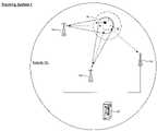
- FIG. 1shows an exemplary embodiment of an tracking system according to the present invention
- FIG. 2shows an exemplary embodiment of a method according to the present invention.
- An exemplary embodiment of the present inventionis a system and method for locating assets (e.g., a mobile unit (“MU”), an RF tag, etc.) in a wireless communications network.
- the present inventionprovides for improved accuracy over conventional asset locating systems by employing an asset locating and tracking system and steered or switched signal beams.
- the present inventionmay be used, for example, in applications requiring accuracy in asset location and tracking, and for data communications featuring extended range and mobile power savings.
- FIG. 1shows an exemplary embodiment of a tracking system 1 according to the present invention.
- the tracking system 1may be utilized in a wireless network 100 , such as a wireless local area network (“WLAN”), which operates according to a communication protocol adopted by IEEE.
- WLANwireless local area network
- the WLAN and any wireless computing devices thereinmay utilize an 802.11 (e.g., 802.11b) communication protocol for conducting wireless communications.
- 802.11e.g., 802.11b
- the tracking system 1 of the present inventionmay be utilized in an indoor environment (e.g., a warehouse, retail location, etc.), as well as an outdoor environment (e.g., parks, cities, etc.).
- the wireless computing devices in the network 100may include a plurality of access points (“APs”) (e.g., APs 110 , 112 , and 114 ) in communication with a computing arrangement (e.g., a server 20 ).
- APsaccess points
- Each of the APs 110 , 112 , 114may be a conventional wireless access point, and in one exemplary embodiment, each AP 110 , 112 , 114 includes a smart antenna (e.g., switched beam, adaptive array, etc.).
- the smart antennamay provide a steered and/or switched beam capability, such that the AP may dynamically direct a transmission/reception in response to an RF environment. That is, the AP may direct and/or switch to one or more beams aimed toward a predetermined location within the network 100 .
- the APs 110 , 112 , 114 and the server 20may work in conjunction to locate and track an asset within the network 100 .
- the assetis a mobile unit (“MU”) 30 which is located within an RF coverage area of at least one of the APs 110 , 112 , 114 .
- the MU 30may be any wireless computing device (e.g., PDA, scanner, cell phone, laptop, network card and PC, handheld computer, etc.).
- the assetmay include any object (e.g., device, good, animal) which may have an RF transmitter and/or an RF tag attached thereto.
- the MU 30itself may include an RF tag 40 attached thereto.
- the server 20may determine a location of the MU 30 within the network 100 .
- the server 20may instruct each of the APs 110 , 112 , 114 to initiate a coarse location operation.
- the coarse location operationcorresponds to location determination using an RSSI.
- the coarse location operationmay cause each AP 110 , 112 , 114 to transmit a signal to the MU 30 .
- Each AP 110 , 112 , 114may subsequently receive an acknowledgment signal from the MU 30 , confirming receipt of the signal sent by the AP.
- the MU 30may transmit signal strength data which corresponds to a strength of the signal which was transmitted by each AP and received by the MU 30 .
- Each AP 110 , 112 , 114may further record signal strength data which corresponds to a strength of the acknowledgment signal received by each AP 110 , 112 , 114 .
- each AP 110 , 112 , 114may include a receiver to conduct conventional wireless communication, and be equipped with a further receiver for tracking the asset, as will be described herein.
- Each APmay then forward one or both of the signal strength datum to the server 20 .
- the server 20may utilize the signal strength datum to determine a coarse location 50 of the MU 30 within the network 100 .
- each transmission from the MU 30 to each AP 110 , 112 , 114may include the signal strength data from a prior transmission which was received by the MU 30 .
- each AP 110 , 112 , 114may record and store (e.g., buffer) one or more signal strength datum from a prior transmission which was received thereby from the MU 30 .
- the server 20does not have to wait for each AP 110 , 112 , 114 to transmit the signal to the MU 30 and receive the acknowledgment signal in return.
- the server 20may receive the datum from the prior transmissions which are stored at each AP 110 , 112 , 114 .
- each AP 110 , 112 , 114may transmit the signal strength data from the prior transmission(s), which may include the signal strength data from the MU 30 and/or the AP, to the server 20 .
- the server 20may instruct each AP 110 , 112 , 114 to initiate a fine location operation.
- the fine location operationcorresponds to location determination using a TDOA.
- the server 20may instruct each AP 110 , 112 , 114 to steer its beam or switch to a beam directed toward the coarse location 50 determined by the server 20 .
- the server 20may provide the coarse location 50 to each AP 110 , 112 , 114 which then directs the beam itself.
- Each AP 110 , 112 , 114then waits to receive a signal from the MU 30 and determines a travel time for the signal.
- Each AP 110 , 112 , 114then forwards each travel time to the server 20 which utilizes the travel times to determine a fine location of the MU 30 within the coarse location 50 .
- FIG. 2shows an exemplary embodiment of a method 200 for locating the asset within the network 100 according to the present invention.
- the methodwill be described with reference to the network 100 , APs 110 , 112 , 114 and MU 30 shown in FIG. 1 .
- Those skilled in the artwill understand that other wireless systems having varying configurations, for example, different numbers of WLANs, APs and MUs, may also utilize and/or implement the exemplary method 200 described herein.
- steps 201 – 209 of the method 200describe a first stage for determining the coarse location 50 (e.g., an approximate location or a location area) of the MU 30 using a Received Signal Strength Indication (“RSSI”).
- the first stagee.g., RSSI stage
- the first stagemay include a power measurement reading (e.g., a strength) of a signal by the MU 30 and/or the APs 110 , 112 , 114 .
- the server 20may initiate a tracking process of the MU 30 .
- the tracking processmay include the first stage for determining the coarse location 50 of the MU 30 , and a second stage for determining the fine location of the MU 30 within the coarse location 50 .
- the server 20may respond to a request to determine the location of the MU 30 , or the server may automatically determine the location of the MU 30 at predetermined intervals (e.g., every 2 hours) or upon certain conditions (e.g., when the MU 30 is powered on).
- an operator or proprietor of the network 100may initiate the tracking process using the server 20 .
- a further MUmay initiate the tracking process.
- a user of the further MUmay desire to know where the MU 30 is within the network.
- the MU 30 or a user thereofmay desire to know a certain location within the network 100 (e.g., a recharging station, a product within a store, etc.).
- the server 20 , the operator of the network 100 and/or the MU 30may initiate the tracking process.
- first datais generated.
- the first datamay include first signal strength data (“FSSD”) and/or second signal strength data (“SSSD”).
- the FSSDis indicative of a strength of a first signal which is transmitted by the MU 30 and received by at least three APs including, e.g., APs 110 , 112 , 114 .
- the SSSDis indicative of a strength of a second signal which is transmitted by at least three APs (e.g., APs 110 , 112 , 114 ) and received by the MU 30 .
- the FSSD and/or the SSSDmay include the RF tag 40 identification, an identifier of the MU 30 , etc.
- the server 20may first determine the at least three APs which are in a communicable range with the MU 30 . That is, the server 20 may review prior signal strength data and/or location data from prior tracking processes to identify those APs which are in a proximity of the MU 30 . In a further exemplary embodiment, the server 20 may instruct a plurality of APs to gather the first data. If more than three APs respond to the server 20 with the first data, the server 20 preferably chooses the three APs with a highest RSSI. In either of these embodiments, the first data may further include a location of each AP 110 , 112 , 114 within the network 100 .
- the APs 110 , 112 , 114transmit the first data to the server 20 .
- the server 20processes the FSSD and/or the SSSD to determine the course location 50 (e.g., a location area) of the MU 30 and/or the RF tag 40 within the network 100 .
- the server 20may utilize the intensity of the FSSD and/or the SSSD, as compared with one or more predetermined geographically marked locations or points (e.g., within the network 100 ).
- the network 100may include a certain number of marked points, each having a measured power reading.
- the marked pointsare static or are less likely to move with respect to the APs 110 , 112 , 114 , thereby allowing the server 20 to compare the FSSD and/or the SSSD with a consistent value(s).
- the server 20may then compare the FSSD and/or the SSSD to the measured power readings of the marked points.
- the server 20 and/or the APs 110 , 112 , 114may store one or more of the measured power readings of the marked points.
- the server 20may instruct the APs 110 , 112 , 114 to gather new power readings from the marked points at the initiation of the tracking process and/or at a predetermined time interval. Based on this comparison, the coarse location 50 of the MU 30 may be determined.
- a fine locationmay be determined during a second stage of the method 200 via a Time Difference Of Arrival (“TDOA”) method (steps 209 – 215 ).
- the fine locatione.g., location of the MU 30 within the coarse location 50
- the fine locationmay be determined using the TDOA method via a steered signal from at least three of the APs 110 , 112 , 114 within the network 100 .
- TDOATime Difference Of Arrival
- the server 20may initiate the second stage of the tracking process of the MU 30 .
- the server 20may not need to initiate the second stage of the tracking process, because the process may continue until the fine location of the MU 30 is determined. That is, the server 20 may simply initiate the tracking process only once, and, as a result, output/determine the fine location of the MU 30 within the network 100 .
- second datais generated.
- the second datamay be collected by the APs 110 , 112 , 114 according to the TDOA mechanism described above. That is, each AP 110 , 112 , 114 and/or the server 20 may calculate the travel time of a signal which was transmitted by the MU 30 and received by each AP 110 , 112 , 114 .
- the server 20may indicate the coarse location 50 of the APs 110 , 112 , 114 , and instruct each to direct (or switch to) its beam which is pointed thereto.
- the use of the smart antenna at each AP 110 , 112 , 114may provide for a more precise determination of the fine location of the MU 30 .
- the second datamay further include the location of the APs 110 , 112 , 114 , as well as a plurality of data including, for example, the RF tag 40 identification, an identifier of the MU 30 , instructions to the MU 30 to activate a response mode, etc.
- step 213the APs 110 , 112 , 114 transmit the second data to the server 20 .
- the server 20processes the second data to determine the fine location of the MU 30 .
- the server 20utilizes a software application which includes, for example, a triangulation algorithm that calculates the fine location of the MU 30 within the coarse location 50 .
- the server 20may further compare the fine location to TDOA data generated by the marked points within the network 100 . This comparison may provide a more precise fine location for the MU 30 .
- Advantages of the present inventioninclude power savings in the MU 30 and/or the RF tag 40 . Furthermore, the tracking process may provide for higher accuracy in location determination due to reduced multipath from beam steering/switching. The present invention may be employed in wireless networks without requiring hardware or software modifications to the MU 30 and/or the RF tag 40 .
- a further advantage of the present inventionis the enhanced detection of rogue MUs and APs within the network 100 .
- introduction and/or entry of an MU and/or an AP into the network 100may require a hardware and/or firmware change to respond to requests by the server 20 .
- the present inventionmay provide for improved location-based security and network integrity.
- the present inventionhas been described with reference to an embodiment having the MU 30 , the RF tag 40 , the network 100 , and APs 110 , 112 , 114 .
- One skilled in the artwould understand that the present invention may also be successfully implemented, for example, for a plurality of MU's 30 , RF tags 40 , APs 110 , 112 , 114 and/or a plurality of the WLANs. Accordingly, various modifications and changes may be made to the embodiments without departing from the broadest spirit and scope of the present invention as set forth in the claims that follow.
- the specification and drawingsare accordingly to be regarded in an illustrative rather than restrictive sense.
Landscapes
- Engineering & Computer Science (AREA)
- Physics & Mathematics (AREA)
- General Physics & Mathematics (AREA)
- Radar, Positioning & Navigation (AREA)
- Remote Sensing (AREA)
- Computer Networks & Wireless Communication (AREA)
- Signal Processing (AREA)
- Mobile Radio Communication Systems (AREA)
- Position Fixing By Use Of Radio Waves (AREA)
Abstract
Description
Claims (20)
Priority Applications (7)
| Application Number | Priority Date | Filing Date | Title |
|---|---|---|---|
| US11/067,127US7174172B2 (en) | 2005-02-25 | 2005-02-25 | System and method for asset location in wireless networks |
| CA2599406ACA2599406C (en) | 2005-02-25 | 2006-02-21 | System and method for asset location in wireless networks |
| CN2006800059653ACN101129078B (en) | 2005-02-25 | 2006-02-21 | System and method for asset location in wireless networks |
| EP06735572.7AEP1851978B1 (en) | 2005-02-25 | 2006-02-21 | System and method for asset location in wireless networks |
| PCT/US2006/005978WO2006093710A2 (en) | 2005-02-25 | 2006-02-21 | System and method for asset location in wireless networks |
| US11/635,099US7373154B2 (en) | 2005-02-25 | 2006-12-07 | System and method for asset location in wireless networks |
| US12/062,725US7778649B2 (en) | 2005-02-25 | 2008-04-04 | System and method for asset location in wireless networks |
Applications Claiming Priority (1)
| Application Number | Priority Date | Filing Date | Title |
|---|---|---|---|
| US11/067,127US7174172B2 (en) | 2005-02-25 | 2005-02-25 | System and method for asset location in wireless networks |
Related Child Applications (1)
| Application Number | Title | Priority Date | Filing Date |
|---|---|---|---|
| US11/635,099ContinuationUS7373154B2 (en) | 2005-02-25 | 2006-12-07 | System and method for asset location in wireless networks |
Publications (2)
| Publication Number | Publication Date |
|---|---|
| US20060194587A1 US20060194587A1 (en) | 2006-08-31 |
| US7174172B2true US7174172B2 (en) | 2007-02-06 |
Family
ID=36932530
Family Applications (3)
| Application Number | Title | Priority Date | Filing Date |
|---|---|---|---|
| US11/067,127Expired - LifetimeUS7174172B2 (en) | 2005-02-25 | 2005-02-25 | System and method for asset location in wireless networks |
| US11/635,099Expired - LifetimeUS7373154B2 (en) | 2005-02-25 | 2006-12-07 | System and method for asset location in wireless networks |
| US12/062,725Active2026-03-16US7778649B2 (en) | 2005-02-25 | 2008-04-04 | System and method for asset location in wireless networks |
Family Applications After (2)
| Application Number | Title | Priority Date | Filing Date |
|---|---|---|---|
| US11/635,099Expired - LifetimeUS7373154B2 (en) | 2005-02-25 | 2006-12-07 | System and method for asset location in wireless networks |
| US12/062,725Active2026-03-16US7778649B2 (en) | 2005-02-25 | 2008-04-04 | System and method for asset location in wireless networks |
Country Status (5)
| Country | Link |
|---|---|
| US (3) | US7174172B2 (en) |
| EP (1) | EP1851978B1 (en) |
| CN (1) | CN101129078B (en) |
| CA (1) | CA2599406C (en) |
| WO (1) | WO2006093710A2 (en) |
Cited By (7)
| Publication number | Priority date | Publication date | Assignee | Title |
|---|---|---|---|---|
| US20070105566A1 (en)* | 2005-02-25 | 2007-05-10 | Jacob Sharony | System and method for asset location in wireless networks |
| US20080266081A1 (en)* | 2007-04-26 | 2008-10-30 | D Agostino Paul P | Wireless transceiver management system and method |
| US20120295653A1 (en)* | 2011-05-20 | 2012-11-22 | Hon Hai Precision Industry Co., Ltd. | Base station apparatus and communication method |
| US9830424B2 (en) | 2013-09-18 | 2017-11-28 | Hill-Rom Services, Inc. | Bed/room/patient association systems and methods |
| US11006246B2 (en) | 2017-02-14 | 2021-05-11 | Fraunhofer-Gesellschaft zur Förderung der angewandten Forschung e.V. | Base station, wireless communications network and methods for operating the same |
| US11216624B2 (en) | 2017-11-30 | 2022-01-04 | Samsung Electronics Co., Ltd. | Apparatus and method for searching and registering tags in local positioning system |
| US11911325B2 (en) | 2019-02-26 | 2024-02-27 | Hill-Rom Services, Inc. | Bed interface for manual location |
Families Citing this family (42)
| Publication number | Priority date | Publication date | Assignee | Title |
|---|---|---|---|---|
| US8244272B2 (en) | 2005-02-22 | 2012-08-14 | Skyhook Wireless, Inc. | Continuous data optimization of moved access points in positioning systems |
| US8369264B2 (en) | 2005-10-28 | 2013-02-05 | Skyhook Wireless, Inc. | Method and system for selecting and providing a relevant subset of Wi-Fi location information to a mobile client device so the client device may estimate its position with efficient utilization of resources |
| SG157355A1 (en)* | 2004-10-29 | 2009-12-29 | Skyhook Wireless Inc | Location beacon database and server, method of building location beacon database, and location based service using same |
| US7738884B2 (en)* | 2005-06-28 | 2010-06-15 | Microsoft Corporation | Positioning service utilizing existing radio base stations |
| US20080161011A1 (en)* | 2006-12-29 | 2008-07-03 | Motorola, Inc. | Method enabling indoor local positioning and movement tracking in wifi capable mobile terminals |
| US8400268B1 (en) | 2007-07-25 | 2013-03-19 | Pinpoint Technologies Inc. | End to end emergency response |
| US8026814B1 (en)* | 2007-07-25 | 2011-09-27 | Pinpoint Technologies Inc. | Wireless mesh network for an asset tracking system |
| US8050690B2 (en) | 2007-08-14 | 2011-11-01 | Mpanion, Inc. | Location based presence and privacy management |
| US12439340B2 (en) | 2007-08-14 | 2025-10-07 | Mpanion, Inc. | Real-time location and presence using a push-location client and server |
| US8583079B2 (en) | 2007-08-14 | 2013-11-12 | Mpanion, Inc. | Rich presence status based on location, activity, availability and transit status of a user |
| US8489111B2 (en) | 2007-08-14 | 2013-07-16 | Mpanion, Inc. | Real-time location and presence using a push-location client and server |
| GB0803348D0 (en)* | 2008-02-25 | 2008-04-02 | Rhodes Mark | Shallow water radio communications network |
| US8155666B2 (en) | 2008-06-16 | 2012-04-10 | Skyhook Wireless, Inc. | Methods and systems for determining location using a cellular and WLAN positioning system by selecting the best cellular positioning system solution |
| US8732272B2 (en)* | 2009-09-29 | 2014-05-20 | Qualcomm Incorporated | Methods and apparatus for obtaining integrated content from multiple networks |
| US8638256B2 (en)* | 2009-09-29 | 2014-01-28 | Skyhook Wireless, Inc. | Accuracy and performance of a hybrid positioning system |
| US8531288B1 (en) | 2009-11-09 | 2013-09-10 | Carnegie Mellon University | System and method for collaborative resource tracking |
| US20110321055A1 (en)* | 2010-06-04 | 2011-12-29 | Enfora, Inc. | Transportation asset manager |
| KR101121907B1 (en)* | 2010-06-09 | 2012-03-20 | 엘지이노텍 주식회사 | Real time locating system and method using directional antennas |
| US8325019B2 (en)* | 2010-09-13 | 2012-12-04 | Ricoh Company, Ltd. | Motion tracking techniques for RFID tags |
| US8483714B2 (en)* | 2010-10-06 | 2013-07-09 | Sony Corporation | Method and apparatus for identification of local beacon systems |
| CN103119999A (en)* | 2010-10-06 | 2013-05-22 | 索尼爱立信移动通讯有限公司 | Mobile device for low power identification of its position and a method therefore |
| US8890746B2 (en) | 2010-11-03 | 2014-11-18 | Skyhook Wireless, Inc. | Method of and system for increasing the reliability and accuracy of location estimation in a hybrid positioning system |
| US9389300B2 (en) | 2011-12-22 | 2016-07-12 | Intel Corporation | Mechanism for employing and facilitating geodetic triangulation for determining global positioning of computing devices |
| US9622027B2 (en)* | 2012-06-15 | 2017-04-11 | Qualcomm Incorporated | Systems and methods for network centric WLAN location of a mobile device |
| US9678194B2 (en) | 2012-08-14 | 2017-06-13 | Qualcomm Incorporated | Positioning using observer-based time-of-arrival measurements |
| US9066202B2 (en)* | 2012-08-14 | 2015-06-23 | Qualcomm Incorporated | Positioning using observer-based time-of-arrival measurements |
| WO2014036150A1 (en)* | 2012-08-28 | 2014-03-06 | Interdigital Patent Holdings, Inc. | Method for handover of a communication link using a primary beam |
| US8922344B2 (en) | 2012-10-25 | 2014-12-30 | Symbol Technologies, Inc. | Detecting rogue radio frequency based tags based on locationing |
| CN103310623A (en)* | 2013-04-01 | 2013-09-18 | 北京福星晓程电子科技股份有限公司 | Method and device for determining region of ammeter by detecting signal intensity |
| CN205692300U (en) | 2013-09-29 | 2016-11-16 | Invue安全产品公司 | A security system used to ensure goods are not stolen |
| US9913092B2 (en)* | 2014-06-06 | 2018-03-06 | The Hong Kong University Of Science And Technology | Mitigating signal noise for fingerprint-based indoor localization |
| US10223881B2 (en) | 2015-02-18 | 2019-03-05 | Invue Security Products Inc. | System and method for calibrating a wireless security range |
| US10482739B2 (en) | 2015-06-25 | 2019-11-19 | Invue Security Products Inc. | Wireless merchandise security system |
| GB2546099B (en)* | 2016-01-08 | 2019-05-29 | Samsung Electronics Co Ltd | Initial access method |
| DE102016216562B4 (en)* | 2016-09-01 | 2021-08-12 | Continental Automotive Gmbh | Method and device for locating a mobile terminal, in particular in the form of a mobile radio terminal for an in particular cellular mobile radio network, by a device on the part of a motor vehicle |
| CN107959919B (en)* | 2017-12-07 | 2019-03-19 | 北京三快在线科技有限公司 | The localization method of mobile terminal, calculates equipment and storage medium at device |
| US10601493B2 (en)* | 2018-02-23 | 2020-03-24 | Precision Optical Transceivers Inc. | Disadvantaged node discovery |
| JP7382487B2 (en)* | 2019-08-15 | 2023-11-16 | ソニーグループ株式会社 | Method and device for on-demand positioning related application data |
| US11917488B2 (en) | 2019-09-13 | 2024-02-27 | Troverlo, Inc. | Passive asset tracking using observations of pseudo Wi-Fi access points |
| US11589187B2 (en) | 2019-09-13 | 2023-02-21 | Troverlo, Inc. | Passive sensor tracking using observations of Wi-Fi access points |
| US11622234B2 (en) | 2019-09-13 | 2023-04-04 | Troverlo, Inc. | Passive asset tracking using observations of Wi-Fi access points |
| US10956690B1 (en) | 2019-09-25 | 2021-03-23 | International Business Machines Corporation | Set-based object management system |
Citations (3)
| Publication number | Priority date | Publication date | Assignee | Title |
|---|---|---|---|---|
| US20040162084A1 (en)* | 2003-02-14 | 2004-08-19 | Atheros Communications, Inc. | Positioning with wireless local area networks and WLAN-aided global positioning systems |
| US20050037775A1 (en)* | 2003-06-27 | 2005-02-17 | Mark Moeglein | Method and apparatus for wireless network hybrid positioning |
| US20060009240A1 (en)* | 2004-07-06 | 2006-01-12 | Mr. Daniel Katz | A wireless location determining device |
Family Cites Families (13)
| Publication number | Priority date | Publication date | Assignee | Title |
|---|---|---|---|---|
| US5873040A (en)* | 1996-08-13 | 1999-02-16 | International Business Machines Corporation | Wireless 911 emergency location |
| US6195556B1 (en)* | 1997-07-15 | 2001-02-27 | Metawave Communications Corporation | System and method of determining a mobile station's position using directable beams |
| US5926133A (en)* | 1997-07-21 | 1999-07-20 | Denso Corporation | Differentially corrected position location system and method for mobile communication networks |
| IT1320072B1 (en)* | 2000-05-04 | 2003-11-12 | Cselt Centro Studi Lab Telecom | PROCEDURE AND SYSTEM FOR THE DETERMINATION OF GEOGRAPHICAL COORDINATES IN MOBILE COMMUNICATION NETWORKS AND THE RELATIVE MOBILE RECEIVER. |
| BR0107383A (en)* | 2000-11-14 | 2002-11-05 | Symbol Technologies Inc | Wireless receiver station clock synchronization system and method |
| US7551931B2 (en)* | 2001-01-24 | 2009-06-23 | Motorola, Inc. | Method and system for validating a mobile station location fix |
| US6775242B2 (en)* | 2001-07-09 | 2004-08-10 | Qualcomm Incorporated | Method and apparatus for time-aligning transmissions from multiple base stations in a CDMA communication system |
| FI20021206L (en)* | 2002-06-20 | 2003-12-21 | Sonera Oyj | Reference-based positioning |
| US20030235172A1 (en)* | 2002-06-24 | 2003-12-25 | Intel Corporation | Asset tracking methods and apparatus |
| US6865395B2 (en)* | 2002-08-08 | 2005-03-08 | Qualcomm Inc. | Area based position determination for terminals in a wireless network |
| WO2005062066A2 (en)* | 2003-10-22 | 2005-07-07 | Awarepoint Corporation | Wireless position location and tracking system |
| US7647164B2 (en)* | 2004-04-21 | 2010-01-12 | Computer Associates Think, Inc. | Web service for mobile device tracking |
| US7174172B2 (en)* | 2005-02-25 | 2007-02-06 | Symbol Technologies, Inc. | System and method for asset location in wireless networks |
- 2005
- 2005-02-25USUS11/067,127patent/US7174172B2/ennot_activeExpired - Lifetime
- 2006
- 2006-02-21WOPCT/US2006/005978patent/WO2006093710A2/enactiveApplication Filing
- 2006-02-21CACA2599406Apatent/CA2599406C/ennot_activeExpired - Fee Related
- 2006-02-21CNCN2006800059653Apatent/CN101129078B/enactiveActive
- 2006-02-21EPEP06735572.7Apatent/EP1851978B1/enactiveActive
- 2006-12-07USUS11/635,099patent/US7373154B2/ennot_activeExpired - Lifetime
- 2008
- 2008-04-04USUS12/062,725patent/US7778649B2/enactiveActive
Patent Citations (3)
| Publication number | Priority date | Publication date | Assignee | Title |
|---|---|---|---|---|
| US20040162084A1 (en)* | 2003-02-14 | 2004-08-19 | Atheros Communications, Inc. | Positioning with wireless local area networks and WLAN-aided global positioning systems |
| US20050037775A1 (en)* | 2003-06-27 | 2005-02-17 | Mark Moeglein | Method and apparatus for wireless network hybrid positioning |
| US20060009240A1 (en)* | 2004-07-06 | 2006-01-12 | Mr. Daniel Katz | A wireless location determining device |
Cited By (16)
| Publication number | Priority date | Publication date | Assignee | Title |
|---|---|---|---|---|
| US20070105566A1 (en)* | 2005-02-25 | 2007-05-10 | Jacob Sharony | System and method for asset location in wireless networks |
| US7373154B2 (en)* | 2005-02-25 | 2008-05-13 | Symbol Technologies, Inc. | System and method for asset location in wireless networks |
| US20080182593A1 (en)* | 2005-02-25 | 2008-07-31 | Jacob Sharony | System and Method for Asset Location in Wireless Networks |
| US7778649B2 (en)* | 2005-02-25 | 2010-08-17 | Symbol Technologies, Inc. | System and method for asset location in wireless networks |
| US20080266081A1 (en)* | 2007-04-26 | 2008-10-30 | D Agostino Paul P | Wireless transceiver management system and method |
| US7605697B2 (en)* | 2007-04-26 | 2009-10-20 | Honeywell International, Inc. | Wireless transceiver management system and method |
| US20120295653A1 (en)* | 2011-05-20 | 2012-11-22 | Hon Hai Precision Industry Co., Ltd. | Base station apparatus and communication method |
| US8483721B2 (en)* | 2011-05-20 | 2013-07-09 | Hon Hai Precision Industry Co., Ltd. | Base station apparatus and communication method |
| US9830424B2 (en) | 2013-09-18 | 2017-11-28 | Hill-Rom Services, Inc. | Bed/room/patient association systems and methods |
| US11011267B2 (en) | 2013-09-18 | 2021-05-18 | Hill-Rom Services, Inc. | Bed/room/patient association systems and methods |
| US12354731B2 (en) | 2013-09-18 | 2025-07-08 | Hill-Rom Services, Inc. | Bed/room/patient association systems and methods |
| US11006246B2 (en) | 2017-02-14 | 2021-05-11 | Fraunhofer-Gesellschaft zur Förderung der angewandten Forschung e.V. | Base station, wireless communications network and methods for operating the same |
| US11216624B2 (en) | 2017-11-30 | 2022-01-04 | Samsung Electronics Co., Ltd. | Apparatus and method for searching and registering tags in local positioning system |
| US11620459B2 (en) | 2017-11-30 | 2023-04-04 | Samsung Electronics Co., Ltd. | Apparatus and method for searching and registering tags in local positioning system |
| US11911325B2 (en) | 2019-02-26 | 2024-02-27 | Hill-Rom Services, Inc. | Bed interface for manual location |
| US12396907B2 (en) | 2019-02-26 | 2025-08-26 | Hill-Rom Services, Inc. | Bed interface for manual location |
Also Published As
| Publication number | Publication date |
|---|---|
| CN101129078B (en) | 2011-04-20 |
| CA2599406A1 (en) | 2006-09-08 |
| US20080182593A1 (en) | 2008-07-31 |
| US20060194587A1 (en) | 2006-08-31 |
| WO2006093710A2 (en) | 2006-09-08 |
| CA2599406C (en) | 2013-10-01 |
| US7373154B2 (en) | 2008-05-13 |
| CN101129078A (en) | 2008-02-20 |
| WO2006093710A3 (en) | 2007-03-15 |
| EP1851978B1 (en) | 2013-11-20 |
| EP1851978A2 (en) | 2007-11-07 |
| US20070105566A1 (en) | 2007-05-10 |
| EP1851978A4 (en) | 2012-03-28 |
| US7778649B2 (en) | 2010-08-17 |
Similar Documents
| Publication | Publication Date | Title |
|---|---|---|
| US7174172B2 (en) | System and method for asset location in wireless networks | |
| US7019663B2 (en) | RF tracking system and method | |
| US8253539B2 (en) | Rfid reader management system and method | |
| US8433337B2 (en) | RSS-based DOA indoor location estimation system and method | |
| US8818408B2 (en) | Real-time network node location system and method | |
| CN101625406A (en) | Positioning system, positioning method, and positioning program | |
| CN102043151A (en) | Mobile terminal and method for positioning based on radio frequency identification | |
| KR102214499B1 (en) | indoor positioning system and method using global positioning system location information mapping | |
| KR101121907B1 (en) | Real time locating system and method using directional antennas | |
| EP3550890B1 (en) | Method for recognizing line-of-sight path, and wireless device | |
| CN117368952A (en) | Fusion positioning method, device, equipment, storage medium and chip of user equipment | |
| CN114051201A (en) | Indoor positioning method based on genetic algorithm optimization | |
| US20110244883A1 (en) | Method and mobile radio terminal device to determine position within mobile radio networks by means of direction finding | |
| JP2006343161A (en) | POSITIONING SYSTEM, RADIO TERMINAL DEVICE, POSITIONING METHOD USED FOR THEM, AND PROGRAM THEREOF | |
| Chothani et al. | RFID-based location tracking system using a RSS and DA | |
| US11714159B2 (en) | Cooperative target positioning system | |
| Salama et al. | Using RFID technology in finding position and tracking based on RSSI | |
| KR102275265B1 (en) | Method and Apparatus for Cooperative Positioning | |
| Shirke et al. | Analysis of RFID Based Positioning Technique Using Received Signal Strength and Directional Antenna | |
| Sastry et al. | On Locating Intelligent Tags | |
| Papapostolou et al. | Considerations for RFID-based indoor simultaneous tracking | |
| Madguni et al. | A Survey on Indoor Positioning System | |
| JP2025005489A (en) | Location determination system and location determination method |
Legal Events
| Date | Code | Title | Description |
|---|---|---|---|
| AS | Assignment | Owner name:SYMBOL TECHNOLOGIES, INC., NEW YORK Free format text:ASSIGNMENT OF ASSIGNORS INTEREST;ASSIGNORS:SHARONY, JACOB;KATZ, JOSEPH;REEL/FRAME:016508/0634;SIGNING DATES FROM 20050322 TO 20050324 | |
| FEPP | Fee payment procedure | Free format text:PAYOR NUMBER ASSIGNED (ORIGINAL EVENT CODE: ASPN); ENTITY STATUS OF PATENT OWNER: LARGE ENTITY | |
| STCF | Information on status: patent grant | Free format text:PATENTED CASE | |
| FPAY | Fee payment | Year of fee payment:4 | |
| FPAY | Fee payment | Year of fee payment:8 | |
| AS | Assignment | Owner name:MORGAN STANLEY SENIOR FUNDING, INC. AS THE COLLATERAL AGENT, MARYLAND Free format text:SECURITY AGREEMENT;ASSIGNORS:ZIH CORP.;LASER BAND, LLC;ZEBRA ENTERPRISE SOLUTIONS CORP.;AND OTHERS;REEL/FRAME:034114/0270 Effective date:20141027 Owner name:MORGAN STANLEY SENIOR FUNDING, INC. AS THE COLLATE Free format text:SECURITY AGREEMENT;ASSIGNORS:ZIH CORP.;LASER BAND, LLC;ZEBRA ENTERPRISE SOLUTIONS CORP.;AND OTHERS;REEL/FRAME:034114/0270 Effective date:20141027 | |
| AS | Assignment | Owner name:SYMBOL TECHNOLOGIES, LLC, NEW YORK Free format text:CHANGE OF NAME;ASSIGNOR:SYMBOL TECHNOLOGIES, INC.;REEL/FRAME:036083/0640 Effective date:20150410 | |
| AS | Assignment | Owner name:SYMBOL TECHNOLOGIES, INC., NEW YORK Free format text:RELEASE BY SECURED PARTY;ASSIGNOR:MORGAN STANLEY SENIOR FUNDING, INC.;REEL/FRAME:036371/0738 Effective date:20150721 | |
| MAFP | Maintenance fee payment | Free format text:PAYMENT OF MAINTENANCE FEE, 12TH YEAR, LARGE ENTITY (ORIGINAL EVENT CODE: M1553) Year of fee payment:12 |