US7174007B1 - Method and apparatus providing caller identification telephone service with a real time audio message - Google Patents
Method and apparatus providing caller identification telephone service with a real time audio messageDownload PDFInfo
- Publication number
- US7174007B1 US7174007B1US09/553,125US55312500AUS7174007B1US 7174007 B1US7174007 B1US 7174007B1US 55312500 AUS55312500 AUS 55312500AUS 7174007 B1US7174007 B1US 7174007B1
- Authority
- US
- United States
- Prior art keywords
- telephone apparatus
- audio message
- called telephone
- called
- audio
- Prior art date
- Legal status (The legal status is an assumption and is not a legal conclusion. Google has not performed a legal analysis and makes no representation as to the accuracy of the status listed.)
- Expired - Fee Related
Links
- 238000000034methodMethods0.000titleclaimsdescription12
- 230000005236sound signalEffects0.000claimsabstractdescription10
- 238000001514detection methodMethods0.000claims1
- 238000010586diagramMethods0.000description6
- 238000007792additionMethods0.000description1
- 238000004891communicationMethods0.000description1
- 238000012986modificationMethods0.000description1
- 230000004048modificationEffects0.000description1
- 238000006467substitution reactionMethods0.000description1
- 230000001960triggered effectEffects0.000description1
Images


Classifications
- H—ELECTRICITY
- H04—ELECTRIC COMMUNICATION TECHNIQUE
- H04M—TELEPHONIC COMMUNICATION
- H04M1/00—Substation equipment, e.g. for use by subscribers
- H04M1/57—Arrangements for indicating or recording the number of the calling subscriber at the called subscriber's set
- H04M1/575—Means for retrieving and displaying personal data about calling party
- H04M1/578—Means for retrieving and displaying personal data about calling party associated with a synthesized vocal announcement
- H—ELECTRICITY
- H04—ELECTRIC COMMUNICATION TECHNIQUE
- H04M—TELEPHONIC COMMUNICATION
- H04M1/00—Substation equipment, e.g. for use by subscribers
- H04M1/72—Mobile telephones; Cordless telephones, i.e. devices for establishing wireless links to base stations without route selection
- H04M1/724—User interfaces specially adapted for cordless or mobile telephones
- H04M1/72403—User interfaces specially adapted for cordless or mobile telephones with means for local support of applications that increase the functionality
- H04M1/7243—User interfaces specially adapted for cordless or mobile telephones with means for local support of applications that increase the functionality with interactive means for internal management of messages
- H04M1/72433—User interfaces specially adapted for cordless or mobile telephones with means for local support of applications that increase the functionality with interactive means for internal management of messages for voice messaging, e.g. dictaphones
Definitions
- the present inventionrelates generally to a method and apparatus for providing caller identification in telephone systems and, more particularly, concerns providing a real time audio message in a telephone system before a connection is established between a calling party and a called party.
- Conventional Caller ID equipmentprovides an identification of the calling party to the called party's telephone customer premises equipment before a telephone connection is established. That is, the Caller ID information is provided to the called party while his telephone equipment remains in an “on-hook” state. Specifically, the central office alerts a called party to an incoming message by ringing his telephone equipment. A ringing signal is applied to the telephone equipment intermittently, with a silent interval being provided between consecutive rings of telephone equipment. When the called party lifts the telephone receiver, the telephone equipment assumes an “off-hook” state, but prior to that time, it remains in an “on-hook” state. Generally, caller ID information is transmitted to the called party's telephone equipment during the “on-hook” state in the silent interval between the first and second rings, but it may come prior to the first ring, after which the Caller ID information is displayed to the called party.
- a shortcoming of conventional Caller ID serviceis that it does not identify the actual calling party, but only the telephone equipment from which the call is being made. When a party is identified, it is registered owner of the telephone equipment from which the call is being made. Thus, when the calling party calls from telephone equipment which is shared among many individuals, from a telephone at a site he is only visiting, from a pay telephone, or through a PBX, the called party cannot identify the actual calling party without going “off-hook” on this telephone equipment and speaking to the calling party. This, however, defeats the intended purpose of Caller ID service.
- a Caller ID servicewhich permits the calling party to speak a real time audio message that can be received and played by the called party's Caller ID equipment while his telephone equipment remains in the “on-hook” state.
- a calling party which has Audio Caller ID (ACID) servicewould speaker a short audio message before dialing the called party. That message is converted to digital form, optionally compressed, and transferred to the called party in a manner similar to conventional Caller ID information.
- the called party's Caller ID equipmentoperates in the conventional manner, except that the received Audio Caller ID signal is recognized as an audio signal.
- a decoderis provided to convert the digital signal to an analog audio signal, and this analog signal is provided to a speaker, which plays back the calling party's audio message.
- Audio Caller ID operationis preserved when Audio Caller ID service is provided. This is achieved by sending the Audio Caller ID data in the silent interval following the second ring.
- the audio Caller ID equipmenttreats any signal received after the first ring as a conventional caller ID signal and any signal received after the second ring as an Audio Caller ID signal.
- An Audio Caller ID receivercould then store conventional Caller ID information in the conventional manner (i.e. allowing the called party to view information about a predetermined number of received calls), while also permitting an audio message or clip to be stored in association with each call.
- the Audio caller IDmay also be sent during rings or regardless of rings.
- FIG. 1is a waveform diagram representing the operating signals in a conventional Caller ID system
- FIG. 2illustrates the message format in a conventional Caller ID system
- FIG. 3is a functional block diagram illustrating the structure of a conventional Caller ID receiver
- FIG. 4is a functional block diagram illustrating a preferred embodiment of an Audio Caller ID receiver in accordance with the present invention.
- FIG. 5is a functional block diagram illustrating a preferred embodiment of an Audio Caller ID transmitter in accordance with the present invention.
- FIG. 1there is illustrated a waveform representing the operating signals in a conventional Caller ID system, all signals being plotted against time. These are the signals typically produced at the central office and presented to the called party's telephone customer premises equipment. Signals 10 and 12 represent the first and second ring signals, which are separated by a first silent interval 14 . Each ringing signal is typically a 20Hz, 86 volt RMS site wave superimposed on ⁇ 48 volts and is produced at the central office on the ring lead to indicate to a customer's called telephone equipment that a telephone call is being received. Each ringing signal has a duration of approximately two seconds, and the silent interval is approximately four seconds. Although not shown in FIG.
- ringing signal 12is followed by a second silent interval, a third ringing signal, a third silent interval, etc. These ringing signals and silent intervals continue until the called party's telephone equipment goes off-hook.
- Caller ID informationis introduced in the first silent interval 14 .
- the Caller ID informationis in the form of a frequency shift keyed (FSK) signal received a short interval 18 after the termination of the ringing signal.
- Interval 18typically has a 300–350 millisecond duration.
- the FSK signal 16contains two carrier frequencies, such as 2100 and 2200 Hz, which represent the low or “0” and higher “1” logic levels, respectively, of a serial data message.
- a continuous frequency signalsuch as 2100 Hz is transmitted, to permit the Caller ID equipment and the called telephone to initialize.
- Thisis followed by an interval 22 during which a modulated FSK signal representing a data message is introduced.
- This data messagecontains the Caller ID information.
- the data messageis typically composed of a series of 8 bit characters each preceded by a start bit and followed by stop bit.
- FIG. 2illustrates a typical message format.
- the first character 30identifies the type of message, such as a calling station directory number, an alpha-numeric message, special service indication etc.
- the second character 32represents the number of characters that follow.
- the following data characters 34represent the actual information to be transmitted, such as the calling station directory number, and the last character 36 is a checksum character, which provides error correction.
- FIG. 3is a functional block diagram of a typical prior art Caller ID receiver 40 , which is connected to a telephone line L in parallel with conventional telephone receiving equipment R.
- Caller ID receiver 40includes a ring detector 42 , which is connected to the telephone line L and controls a normally open switch 44 , which is also connected to the telephone line.
- switch 44At the output of switch 44 , there is provided an AC coupler 46 designed to transmit FSK frequencies, but to block the lower frequency ringing signal.
- the AC coupleris connected to an FSK demodulator 48 , the output of which is provided to a convertor 49 , which provides serial data as an output.
- ring detector 42In operation, when ring detector 42 detects the first ringing signal on telephone line L, it causes switch 44 to close. The ringing signal is, however, blocked by coupler 46 . On the other hand, when signals in the FSK band begin to appear on telephone line L, they are transmitted through coupler 46 to demodulator 48 . The demodulation output signals is then converted by convertor 49 to a serial data stream. Typically, the serial data is provided to a display, so that the Caller ID information may be displayed to the user.
- FIG. 4illustrates a preferred embodiment 50 of an Audio Caller ID receiver in accordance with the present invention.
- receiver 50components which are identical to components incorporated in receiver 40 are identified with the same reference character, operate in the same manner as in receiver 40 , and will not be described further.
- a ring detector 42 ′is connected to telephone line L. This device is similar to a conventional ring detector, except that is includes a counter so that it is able to determine when the second ringing signal is received. It is assumed that receiver 50 will be providing conventional serial data in the same manner as receiver 40 , so that it will be capable of operating as conventional Caller ID receiver as well.
- serial datais, however, also provided to a digital audio decoder 52 , which is enabled by the second signal received from ring detector 42 ′ over lead 51 .
- the output of digital audio decoder 52is provided through audio amplifier 54 to a speaker 56 , or the like. It should also be appreciated that the signal from amplifier 54 could be provided to the ear piece of the telephone set when receiver 50 is part of a integrated unit incorporating a telephone receiver.
- ring detector 42 ′will enable digital audio decoder 52 when it detects the second ring signal. Thereafter, serial data provided at the output of convertor 49 will be converted by decoder 52 from digital audio to an analog audio signal which is amplified and played over speaker 56 . It should be appreciated that the serial data received by decoder 52 may be a compressed digital audio signal, in which case the decoder 52 would include the necessary components to decompress the signal prior to decoding it.
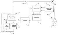
- FIG. 5is a block diagram illustrating a preferred embodiment 60 of an audio Caller ID transmitter in accordance with the present invention.
- Transmitter 60includes an enabling switch, such as a push button 62 which a user presses when he wishes to store an audio message that is to be sent to a receiver.
- Operating switch 62causes a predetermined triggered signal to appear on leads 61 and 63 .
- the signal on lead 61causes a digital audio encoder 62 to be enabled, whereby the operator may digitally encoder an audio signal provided by a microphone 66 and audio amplifier 68 to encoder 64 .
- a digital signal from encoder 64is stored in a storage unit 70 . It should be appreciated that encoder 64 may include components for compressing the digital audio signal.
- Storage unit 70is connected to a converter 72 , which converts digital words stored in unit 70 to a serial data stream.
- the serial data streamis provided through an FSK modulator 74 to a transmitter circuit 76 .
- the output of transmitter circuit 76is coupled to the telephone line L, and the transmitter circuit also receives a control input from the telephone line.
- an off-hook detector 78Also connected to telephone line L is an off-hook detector 78 , which enables transmitter circuit 76 .
- the userpreferably records an audio message prior to going off hook on his telephone transmitter.
- the usermay begin recording when he hears the dial tone. He begins recording by operating the switch 62 , at which point encoder 64 and transmitter circuit 76 are placed in a ready state.
- the userspeaks into the microphone 66 , whereby the audio signal is converted into a digital signal by encoder 64 and, optionally, compressed.
- the digital signalis stored in storage unit 70 , and the user is ready to place his telephone call.
- Off-hook detector 78detects when the user goes off hook and enables transmitting circuit 76 . At this point, transmitting circuit 76 places a predetermined signal on the telephone line, which is recognized by the central office as indicating that a digital audio message is waiting.
- the central officethen receives the telephone number dialed by the user in the usual manner and, when dialing is complete sends a predetermined signal over the telephone line indicating to transmitting circuit 76 that it is ready to receive the audio message. Transmitting circuit 76 detects this signal, enables convertor 72 and enables storage units 70 to output the recorded message.
- Converter 72converts the stored words from storage unit 70 into a serial data stream, which is provided to modulator 74 .
- Modulator 74then produces an FSK signal, which is coupled to telephone line L via AC coupler 46 . This FSK signal is provided to the Audio Caller ID receiver 50 at the site of the receiving party.
- the message format for Audio Caller ID messagescould be similar to that of FIG. 2 , except that character 30 is selected to be unique to an Audio Caller ID signal and character 32 would represents the message length in fractions of a second (e.g., 1 ⁇ 8 second increments).
Landscapes
- Engineering & Computer Science (AREA)
- Signal Processing (AREA)
- Business, Economics & Management (AREA)
- General Business, Economics & Management (AREA)
- Human Computer Interaction (AREA)
- Computer Networks & Wireless Communication (AREA)
- Telephonic Communication Services (AREA)
- Telephone Function (AREA)
Abstract
Description
Claims (12)
Priority Applications (1)
| Application Number | Priority Date | Filing Date | Title |
|---|---|---|---|
| US09/553,125US7174007B1 (en) | 2000-04-19 | 2000-04-19 | Method and apparatus providing caller identification telephone service with a real time audio message |
Applications Claiming Priority (1)
| Application Number | Priority Date | Filing Date | Title |
|---|---|---|---|
| US09/553,125US7174007B1 (en) | 2000-04-19 | 2000-04-19 | Method and apparatus providing caller identification telephone service with a real time audio message |
Publications (1)
| Publication Number | Publication Date |
|---|---|
| US7174007B1true US7174007B1 (en) | 2007-02-06 |
Family
ID=37696689
Family Applications (1)
| Application Number | Title | Priority Date | Filing Date |
|---|---|---|---|
| US09/553,125Expired - Fee RelatedUS7174007B1 (en) | 2000-04-19 | 2000-04-19 | Method and apparatus providing caller identification telephone service with a real time audio message |
Country Status (1)
| Country | Link |
|---|---|
| US (1) | US7174007B1 (en) |
Cited By (5)
| Publication number | Priority date | Publication date | Assignee | Title |
|---|---|---|---|---|
| US20060233354A1 (en)* | 2003-01-30 | 2006-10-19 | Serconet Ltd | Method and system for providing DC power on local telephone Lines |
| US20070165741A1 (en)* | 2005-04-22 | 2007-07-19 | Huawei Technologies Co., Ltd. | Method for Data Transmission Between Switch and Terminal, FSK Processing Module, Terminal, and Switch |
| US20090189397A1 (en)* | 2001-04-26 | 2009-07-30 | Fallbrook Technologies Inc. | Continuously variable transmission |
| US20140078378A1 (en)* | 2011-05-25 | 2014-03-20 | Obzerv Technologies Unc. | Active Imaging Device Having Field of View and Field of Illumination With Corresponding Rectangular Aspect Ratios |
| US10278033B2 (en)* | 2015-06-26 | 2019-04-30 | Samsung Electronics Co., Ltd. | Electronic device and method of providing message via electronic device |
Citations (16)
| Publication number | Priority date | Publication date | Assignee | Title |
|---|---|---|---|---|
| US4551581A (en)* | 1983-07-12 | 1985-11-05 | At&T Bell Laboratories | Method and apparatus for sending a data message to a selected station during a silent interval between ringing |
| US5444767A (en)* | 1994-03-09 | 1995-08-22 | Gregory J. Goetcheus | Systems and methods for recording and delivering personalized audio messages |
| US5631950A (en)* | 1995-07-26 | 1997-05-20 | Lucent Technologies Inc. | Transmission of data message during silent intervals of ringing for selection of terminal equipment |
| US5646979A (en)* | 1995-12-20 | 1997-07-08 | Casio Phonemate, Inc. | Cordless telephone with voice announced calling party identification |
| US5850435A (en)* | 1996-03-01 | 1998-12-15 | U S West, Inc. | Method for audible caller name announcement with call list feature |
| US5867567A (en)* | 1995-06-01 | 1999-02-02 | Brother Kogyo Kabushiki Kaisha | Terminal device for network system |
| US5905786A (en)* | 1997-03-24 | 1999-05-18 | Oakley Telecom, Lc. | Console and extension telephone system |
| US6044148A (en)* | 1997-07-16 | 2000-03-28 | Nortel Networks Corporation | Pre-ring caller identification apparatus and method and call screening therefrom |
| US6178232B1 (en)* | 1998-07-24 | 2001-01-23 | Ameritech Corporation | Method and system for providing enhanced caller identification |
| US6347136B1 (en)* | 1999-07-15 | 2002-02-12 | Winbond Electronics Corporation | Calling party announcement message management systems and methods |
| US6353664B1 (en)* | 1997-12-01 | 2002-03-05 | Agere Systems Guardian Corp. | Caller ID equipment which displays location of caller |
| US6373925B1 (en)* | 1996-06-28 | 2002-04-16 | Siemens Aktiengesellschaft | Telephone calling party announcement system and method |
| US20020090064A1 (en)* | 1997-11-26 | 2002-07-11 | Burg Frederick Murray | System and method for providing call subject information to a called party |
| US6466653B1 (en)* | 1999-01-29 | 2002-10-15 | Ameritech Corporation | Text-to-speech preprocessing and conversion of a caller's ID in a telephone subscriber unit and method therefor |
| US6618474B1 (en)* | 1999-03-08 | 2003-09-09 | Morris Reese | Method and apparatus for providing to a customer a promotional message between ringing signals or after a call waiting tone |
| US6870914B1 (en)* | 1999-01-29 | 2005-03-22 | Sbc Properties, L.P. | Distributed text-to-speech synthesis between a telephone network and a telephone subscriber unit |
- 2000
- 2000-04-19USUS09/553,125patent/US7174007B1/ennot_activeExpired - Fee Related
Patent Citations (17)
| Publication number | Priority date | Publication date | Assignee | Title |
|---|---|---|---|---|
| US4551581A (en)* | 1983-07-12 | 1985-11-05 | At&T Bell Laboratories | Method and apparatus for sending a data message to a selected station during a silent interval between ringing |
| US4551581B1 (en)* | 1983-07-12 | 1995-06-20 | Bell Telephone Labor Inc | Method and apparatus for sending a data message to a selected station during a silent interval between ringing |
| US5444767A (en)* | 1994-03-09 | 1995-08-22 | Gregory J. Goetcheus | Systems and methods for recording and delivering personalized audio messages |
| US5867567A (en)* | 1995-06-01 | 1999-02-02 | Brother Kogyo Kabushiki Kaisha | Terminal device for network system |
| US5631950A (en)* | 1995-07-26 | 1997-05-20 | Lucent Technologies Inc. | Transmission of data message during silent intervals of ringing for selection of terminal equipment |
| US5646979A (en)* | 1995-12-20 | 1997-07-08 | Casio Phonemate, Inc. | Cordless telephone with voice announced calling party identification |
| US5850435A (en)* | 1996-03-01 | 1998-12-15 | U S West, Inc. | Method for audible caller name announcement with call list feature |
| US6373925B1 (en)* | 1996-06-28 | 2002-04-16 | Siemens Aktiengesellschaft | Telephone calling party announcement system and method |
| US5905786A (en)* | 1997-03-24 | 1999-05-18 | Oakley Telecom, Lc. | Console and extension telephone system |
| US6044148A (en)* | 1997-07-16 | 2000-03-28 | Nortel Networks Corporation | Pre-ring caller identification apparatus and method and call screening therefrom |
| US20020090064A1 (en)* | 1997-11-26 | 2002-07-11 | Burg Frederick Murray | System and method for providing call subject information to a called party |
| US6353664B1 (en)* | 1997-12-01 | 2002-03-05 | Agere Systems Guardian Corp. | Caller ID equipment which displays location of caller |
| US6178232B1 (en)* | 1998-07-24 | 2001-01-23 | Ameritech Corporation | Method and system for providing enhanced caller identification |
| US6466653B1 (en)* | 1999-01-29 | 2002-10-15 | Ameritech Corporation | Text-to-speech preprocessing and conversion of a caller's ID in a telephone subscriber unit and method therefor |
| US6870914B1 (en)* | 1999-01-29 | 2005-03-22 | Sbc Properties, L.P. | Distributed text-to-speech synthesis between a telephone network and a telephone subscriber unit |
| US6618474B1 (en)* | 1999-03-08 | 2003-09-09 | Morris Reese | Method and apparatus for providing to a customer a promotional message between ringing signals or after a call waiting tone |
| US6347136B1 (en)* | 1999-07-15 | 2002-02-12 | Winbond Electronics Corporation | Calling party announcement message management systems and methods |
Cited By (8)
| Publication number | Priority date | Publication date | Assignee | Title |
|---|---|---|---|---|
| US20090189397A1 (en)* | 2001-04-26 | 2009-07-30 | Fallbrook Technologies Inc. | Continuously variable transmission |
| US20060233354A1 (en)* | 2003-01-30 | 2006-10-19 | Serconet Ltd | Method and system for providing DC power on local telephone Lines |
| US20070127715A1 (en)* | 2003-01-30 | 2007-06-07 | Serconet Ltd | Method and system for providing DC power on local telephone lines |
| US8107618B2 (en) | 2003-01-30 | 2012-01-31 | Mosaid Technologies Incorporated | Method and system for providing DC power on local telephone lines |
| US8787562B2 (en)* | 2003-01-30 | 2014-07-22 | Conversant Intellectual Property Management Inc. | Method and system for providing DC power on local telephone lines |
| US20070165741A1 (en)* | 2005-04-22 | 2007-07-19 | Huawei Technologies Co., Ltd. | Method for Data Transmission Between Switch and Terminal, FSK Processing Module, Terminal, and Switch |
| US20140078378A1 (en)* | 2011-05-25 | 2014-03-20 | Obzerv Technologies Unc. | Active Imaging Device Having Field of View and Field of Illumination With Corresponding Rectangular Aspect Ratios |
| US10278033B2 (en)* | 2015-06-26 | 2019-04-30 | Samsung Electronics Co., Ltd. | Electronic device and method of providing message via electronic device |
Similar Documents
| Publication | Publication Date | Title |
|---|---|---|
| US7602890B2 (en) | Telephone network messaging | |
| US7206572B2 (en) | Calling party announcement apparatus | |
| US6192116B1 (en) | System and method for generating CID/CIDCW information with a user inputted message | |
| US5915000A (en) | Text teletype writer with caller identification function | |
| US6026152A (en) | Ring count controlled by incoming call related information | |
| GB2308783A (en) | Announcing CLI | |
| US7174007B1 (en) | Method and apparatus providing caller identification telephone service with a real time audio message | |
| KR100336902B1 (en) | Method for selective transmitting response message in telephone | |
| US5802476A (en) | Cordless telephone system having base unit with speaker | |
| JPH11234764A (en) | Audio signal connection method and device therefor | |
| US6636595B1 (en) | Non-KSU message delivery system | |
| US20020042262A1 (en) | Interactive silent response for mobile phone | |
| JP3341850B2 (en) | Incoming terminal | |
| KR100496820B1 (en) | An answering telephone unit for responding voice with alphanumeric message | |
| KR200254224Y1 (en) | Apparatus for announcing a cid number by voice message in a cid service telephone | |
| JPS62125718A (en) | wireless telephone | |
| JP2565276B2 (en) | Wireless selective call receiver | |
| JPH10229433A (en) | Mobile phone | |
| JPH02278947A (en) | Communication device | |
| JPH043145B2 (en) | ||
| JPH0548735A (en) | Detection system for calling subscriber number | |
| JPH06224982A (en) | Telephone terminal equipment | |
| JPS5816658B2 (en) | Kanyushiyasenshingohoushiki | |
| JPS6347170B2 (en) | ||
| JPH11355429A (en) | Answering machine |
Legal Events
| Date | Code | Title | Description |
|---|---|---|---|
| AS | Assignment | Owner name:LUCENT TECHNOLOGIES INC., NEW JERSEY Free format text:ASSIGNMENT OF ASSIGNORS INTEREST;ASSIGNORS:CANNON, JOSEPH M.;JAMPANABOYANA, LAKSHMI N.;JOHANSON, JAMES A.;AND OTHERS;REEL/FRAME:010761/0833 Effective date:20000411 | |
| FEPP | Fee payment procedure | Free format text:PAYOR NUMBER ASSIGNED (ORIGINAL EVENT CODE: ASPN); ENTITY STATUS OF PATENT OWNER: LARGE ENTITY | |
| FPAY | Fee payment | Year of fee payment:4 | |
| FPAY | Fee payment | Year of fee payment:8 | |
| AS | Assignment | Owner name:AVAGO TECHNOLOGIES GENERAL IP (SINGAPORE) PTE. LTD Free format text:ASSIGNMENT OF ASSIGNORS INTEREST;ASSIGNOR:AGERE SYSTEMS LLC;REEL/FRAME:035365/0634 Effective date:20140804 | |
| AS | Assignment | Owner name:BANK OF AMERICA, N.A., AS COLLATERAL AGENT, NORTH CAROLINA Free format text:PATENT SECURITY AGREEMENT;ASSIGNOR:AVAGO TECHNOLOGIES GENERAL IP (SINGAPORE) PTE. LTD.;REEL/FRAME:037808/0001 Effective date:20160201 Owner name:BANK OF AMERICA, N.A., AS COLLATERAL AGENT, NORTH Free format text:PATENT SECURITY AGREEMENT;ASSIGNOR:AVAGO TECHNOLOGIES GENERAL IP (SINGAPORE) PTE. LTD.;REEL/FRAME:037808/0001 Effective date:20160201 | |
| AS | Assignment | Owner name:AVAGO TECHNOLOGIES GENERAL IP (SINGAPORE) PTE. LTD., SINGAPORE Free format text:TERMINATION AND RELEASE OF SECURITY INTEREST IN PATENTS;ASSIGNOR:BANK OF AMERICA, N.A., AS COLLATERAL AGENT;REEL/FRAME:041710/0001 Effective date:20170119 Owner name:AVAGO TECHNOLOGIES GENERAL IP (SINGAPORE) PTE. LTD Free format text:TERMINATION AND RELEASE OF SECURITY INTEREST IN PATENTS;ASSIGNOR:BANK OF AMERICA, N.A., AS COLLATERAL AGENT;REEL/FRAME:041710/0001 Effective date:20170119 | |
| FEPP | Fee payment procedure | Free format text:MAINTENANCE FEE REMINDER MAILED (ORIGINAL EVENT CODE: REM.); ENTITY STATUS OF PATENT OWNER: LARGE ENTITY | |
| AS | Assignment | Owner name:AVAGO TECHNOLOGIES INTERNATIONAL SALES PTE. LIMITE Free format text:MERGER;ASSIGNOR:AVAGO TECHNOLOGIES GENERAL IP (SINGAPORE) PTE. LTD.;REEL/FRAME:047642/0417 Effective date:20180509 | |
| AS | Assignment | Owner name:AVAGO TECHNOLOGIES INTERNATIONAL SALES PTE. LIMITE Free format text:CORRECTIVE ASSIGNMENT TO CORRECT THE EXECUTION DATE OF THE MERGER PREVIOUSLY RECORDED ON REEL 047642 FRAME 0417. ASSIGNOR(S) HEREBY CONFIRMS THE ASSIGNMENT,;ASSIGNOR:AVAGO TECHNOLOGIES GENERAL IP (SINGAPORE) PTE. LTD.;REEL/FRAME:048521/0395 Effective date:20180905 | |
| LAPS | Lapse for failure to pay maintenance fees | Free format text:PATENT EXPIRED FOR FAILURE TO PAY MAINTENANCE FEES (ORIGINAL EVENT CODE: EXP.); ENTITY STATUS OF PATENT OWNER: LARGE ENTITY | |
| STCH | Information on status: patent discontinuation | Free format text:PATENT EXPIRED DUE TO NONPAYMENT OF MAINTENANCE FEES UNDER 37 CFR 1.362 | |
| FP | Lapsed due to failure to pay maintenance fee | Effective date:20190206 |