US7172610B2 - Rotational atherectomy system with stationary cutting elements - Google Patents
Rotational atherectomy system with stationary cutting elementsDownload PDFInfo
- Publication number
- US7172610B2 US7172610B2US10/688,603US68860303AUS7172610B2US 7172610 B2US7172610 B2US 7172610B2US 68860303 AUS68860303 AUS 68860303AUS 7172610 B2US7172610 B2US 7172610B2
- Authority
- US
- United States
- Prior art keywords
- tubular body
- cutter
- rotatable
- distal end
- tip
- Prior art date
- Legal status (The legal status is an assumption and is not a legal conclusion. Google has not performed a legal analysis and makes no representation as to the accuracy of the status listed.)
- Expired - Lifetime, expires
Links
- 238000005520cutting processMethods0.000titleclaimsdescription70
- 239000000463materialSubstances0.000claimsabstractdescription94
- 230000007246mechanismEffects0.000claimsdescription9
- 238000004891communicationMethods0.000claimsdescription3
- 239000002184metalSubstances0.000claimsdescription2
- 229920000642polymerPolymers0.000claims1
- 238000000034methodMethods0.000description36
- 230000009471actionEffects0.000description17
- 208000037260Atherosclerotic PlaqueDiseases0.000description15
- 210000001367arteryAnatomy0.000description13
- 239000012530fluidSubstances0.000description13
- 238000012546transferMethods0.000description12
- 230000006835compressionEffects0.000description11
- 238000007906compressionMethods0.000description11
- 230000001965increasing effectEffects0.000description11
- 210000001519tissueAnatomy0.000description11
- 238000011282treatmentMethods0.000description11
- 230000003466anti-cipated effectEffects0.000description10
- 230000000994depressogenic effectEffects0.000description10
- 230000006870functionEffects0.000description10
- 230000003902lesionEffects0.000description10
- 230000002829reductive effectEffects0.000description10
- 230000008901benefitEffects0.000description9
- 238000001802infusionMethods0.000description9
- 230000002441reversible effectEffects0.000description9
- 230000002966stenotic effectEffects0.000description9
- 239000000853adhesiveSubstances0.000description7
- 230000001070adhesive effectEffects0.000description7
- 230000004323axial lengthEffects0.000description7
- 210000004351coronary vesselAnatomy0.000description7
- 229910001220stainless steelInorganic materials0.000description7
- 238000010276constructionMethods0.000description6
- 230000006378damageEffects0.000description6
- 238000013461designMethods0.000description6
- 230000003014reinforcing effectEffects0.000description6
- 230000002792vascularEffects0.000description6
- FAPWRFPIFSIZLT-UHFFFAOYSA-MSodium chlorideChemical compound[Na+].[Cl-]FAPWRFPIFSIZLT-UHFFFAOYSA-M0.000description5
- 239000002872contrast mediaSubstances0.000description5
- 239000010410layerSubstances0.000description5
- 238000004519manufacturing processMethods0.000description5
- 230000002093peripheral effectEffects0.000description5
- 239000010935stainless steelSubstances0.000description5
- 238000012360testing methodMethods0.000description5
- 210000003484anatomyAnatomy0.000description4
- 230000003143atherosclerotic effectEffects0.000description4
- 238000005452bendingMethods0.000description4
- 239000008280bloodSubstances0.000description4
- 210000004369bloodAnatomy0.000description4
- 239000003990capacitorSubstances0.000description4
- 239000011248coating agentSubstances0.000description4
- 238000000576coating methodMethods0.000description4
- 239000004519greaseSubstances0.000description4
- 230000014759maintenance of locationEffects0.000description4
- 230000000414obstructive effectEffects0.000description4
- 239000002245particleSubstances0.000description4
- 230000000717retained effectEffects0.000description4
- 229920004943Delrin®Polymers0.000description3
- RYECOJGRJDOGPP-UHFFFAOYSA-NEthylureaChemical groupCCNC(N)=ORYECOJGRJDOGPP-UHFFFAOYSA-N0.000description3
- 208000031481Pathologic ConstrictionDiseases0.000description3
- 239000004809TeflonSubstances0.000description3
- 229920006362Teflon®Polymers0.000description3
- 229920005549butyl rubberPolymers0.000description3
- 238000002788crimpingMethods0.000description3
- 229910003460diamondInorganic materials0.000description3
- 239000010432diamondSubstances0.000description3
- 238000001125extrusionMethods0.000description3
- 208000014674injuryDiseases0.000description3
- 238000003780insertionMethods0.000description3
- 230000037431insertionEffects0.000description3
- 239000007788liquidSubstances0.000description3
- -1polyethylenePolymers0.000description3
- 229920001296polysiloxanePolymers0.000description3
- 230000008569processEffects0.000description3
- 230000004044responseEffects0.000description3
- 238000007789sealingMethods0.000description3
- 239000011780sodium chlorideSubstances0.000description3
- 238000005476solderingMethods0.000description3
- 230000000007visual effectEffects0.000description3
- 239000004593EpoxySubstances0.000description2
- 239000004677NylonSubstances0.000description2
- 239000004698PolyethyleneSubstances0.000description2
- 208000027418Wounds and injuryDiseases0.000description2
- 239000003082abrasive agentSubstances0.000description2
- 125000000218acetic acid groupChemical groupC(C)(=O)*0.000description2
- NIXOWILDQLNWCW-UHFFFAOYSA-Nacrylic acid groupChemical groupC(C=C)(=O)ONIXOWILDQLNWCW-UHFFFAOYSA-N0.000description2
- 230000000712assemblyEffects0.000description2
- 238000000429assemblyMethods0.000description2
- 230000005540biological transmissionEffects0.000description2
- 230000008859changeEffects0.000description2
- HVYWMOMLDIMFJA-DPAQBDIFSA-NcholesterolChemical compoundC1C=C2C[C@@H](O)CC[C@]2(C)[C@@H]2[C@@H]1[C@@H]1CC[C@H]([C@H](C)CCCC(C)C)[C@@]1(C)CC2HVYWMOMLDIMFJA-DPAQBDIFSA-N0.000description2
- 229940039231contrast mediaDrugs0.000description2
- 230000008878couplingEffects0.000description2
- 238000010168coupling processMethods0.000description2
- 238000005859coupling reactionMethods0.000description2
- 230000001419dependent effectEffects0.000description2
- 230000003292diminished effectEffects0.000description2
- 230000000694effectsEffects0.000description2
- 230000005489elastic deformationEffects0.000description2
- 230000008713feedback mechanismEffects0.000description2
- 230000012010growthEffects0.000description2
- 238000002347injectionMethods0.000description2
- 239000007924injectionSubstances0.000description2
- 238000009434installationMethods0.000description2
- 230000003993interactionEffects0.000description2
- 239000000314lubricantSubstances0.000description2
- 238000012544monitoring processMethods0.000description2
- 229920001778nylonPolymers0.000description2
- 238000005457optimizationMethods0.000description2
- 229920000647polyepoxidePolymers0.000description2
- 229920000573polyethylenePolymers0.000description2
- 238000003825pressingMethods0.000description2
- 238000010008shearingMethods0.000description2
- 229920002379silicone rubberPolymers0.000description2
- 239000004945silicone rubberSubstances0.000description2
- 210000004872soft tissueAnatomy0.000description2
- 239000007787solidSubstances0.000description2
- 239000000243solutionSubstances0.000description2
- 238000003860storageMethods0.000description2
- 239000000126substanceSubstances0.000description2
- 230000008733traumaEffects0.000description2
- 210000005166vasculatureAnatomy0.000description2
- 210000003462veinAnatomy0.000description2
- 239000004925Acrylic resinSubstances0.000description1
- 229920000178Acrylic resinPolymers0.000description1
- 206010001526Air embolismDiseases0.000description1
- 206010002383Angina PectorisDiseases0.000description1
- 206010003211Arteriosclerosis coronary arteryDiseases0.000description1
- 201000001320AtherosclerosisDiseases0.000description1
- LFQSCWFLJHTTHZ-UHFFFAOYSA-NEthanolChemical compoundCCOLFQSCWFLJHTTHZ-UHFFFAOYSA-N0.000description1
- 206010020772HypertensionDiseases0.000description1
- 229920005383Plexiglas® DR®Polymers0.000description1
- 229920002614Polyether block amidePolymers0.000description1
- 239000004642PolyimideSubstances0.000description1
- 229910000831SteelInorganic materials0.000description1
- 208000006011StrokeDiseases0.000description1
- 239000004830Super GlueSubstances0.000description1
- 208000007536ThrombosisDiseases0.000description1
- 239000002253acidSubstances0.000description1
- 238000013459approachMethods0.000description1
- 230000000903blocking effectEffects0.000description1
- 230000036772blood pressureEffects0.000description1
- 210000004204blood vesselAnatomy0.000description1
- 235000012000cholesterolNutrition0.000description1
- 230000007012clinical effectEffects0.000description1
- 230000000295complement effectEffects0.000description1
- 208000029078coronary artery diseaseDiseases0.000description1
- 230000003247decreasing effectEffects0.000description1
- 230000003111delayed effectEffects0.000description1
- 230000000881depressing effectEffects0.000description1
- 230000035487diastolic blood pressureEffects0.000description1
- 238000006073displacement reactionMethods0.000description1
- 229940079593drugDrugs0.000description1
- 239000003814drugSubstances0.000description1
- 239000000428dustSubstances0.000description1
- 210000003038endotheliumAnatomy0.000description1
- 230000002708enhancing effectEffects0.000description1
- 125000003700epoxy groupChemical group0.000description1
- 239000003822epoxy resinSubstances0.000description1
- 238000005530etchingMethods0.000description1
- 210000001105femoral arteryAnatomy0.000description1
- 239000002657fibrous materialSubstances0.000description1
- 238000007667floatingMethods0.000description1
- 239000003292glueSubstances0.000description1
- 238000000227grindingMethods0.000description1
- 230000035876healingEffects0.000description1
- 230000023597hemostasisEffects0.000description1
- 238000007917intracranial administrationMethods0.000description1
- 238000011068loading methodMethods0.000description1
- 230000007787long-term memoryEffects0.000description1
- 238000003754machiningMethods0.000description1
- 229920002529medical grade siliconePolymers0.000description1
- 230000015654memoryEffects0.000description1
- 208000010125myocardial infarctionDiseases0.000description1
- 230000010412perfusionEffects0.000description1
- 229920000139polyethylene terephthalatePolymers0.000description1
- 239000005020polyethylene terephthalateSubstances0.000description1
- 229920001721polyimidePolymers0.000description1
- 239000013047polymeric layerSubstances0.000description1
- 229920001343polytetrafluoroethylenePolymers0.000description1
- 239000004810polytetrafluoroethyleneSubstances0.000description1
- 238000012545processingMethods0.000description1
- 230000002062proliferating effectEffects0.000description1
- 230000002035prolonged effectEffects0.000description1
- 238000010926purgeMethods0.000description1
- 230000001105regulatory effectEffects0.000description1
- 238000007634remodelingMethods0.000description1
- 230000008439repair processEffects0.000description1
- 238000012552reviewMethods0.000description1
- 210000003752saphenous veinAnatomy0.000description1
- 238000000926separation methodMethods0.000description1
- 239000002356single layerSubstances0.000description1
- 239000007779soft materialSubstances0.000description1
- 239000002904solventSubstances0.000description1
- 238000009987spinningMethods0.000description1
- 229910001256stainless steel alloyInorganic materials0.000description1
- 239000010959steelSubstances0.000description1
- 230000036262stenosisEffects0.000description1
- 208000037804stenosisDiseases0.000description1
- 230000001954sterilising effectEffects0.000description1
- 238000004659sterilization and disinfectionMethods0.000description1
- 229940126585therapeutic drugDrugs0.000description1
- 230000000472traumatic effectEffects0.000description1
- 210000004026tunica intimaAnatomy0.000description1
Images


Classifications
- A—HUMAN NECESSITIES
- A61—MEDICAL OR VETERINARY SCIENCE; HYGIENE
- A61B—DIAGNOSIS; SURGERY; IDENTIFICATION
- A61B17/00—Surgical instruments, devices or methods
- A61B17/32—Surgical cutting instruments
- A61B17/3205—Excision instruments
- A61B17/3207—Atherectomy devices working by cutting or abrading; Similar devices specially adapted for non-vascular obstructions
- A61B17/320758—Atherectomy devices working by cutting or abrading; Similar devices specially adapted for non-vascular obstructions with a rotating cutting instrument, e.g. motor driven
- A—HUMAN NECESSITIES
- A61—MEDICAL OR VETERINARY SCIENCE; HYGIENE
- A61B—DIAGNOSIS; SURGERY; IDENTIFICATION
- A61B17/00—Surgical instruments, devices or methods
- A61B2017/00017—Electrical control of surgical instruments
- A61B2017/00022—Sensing or detecting at the treatment site
- A—HUMAN NECESSITIES
- A61—MEDICAL OR VETERINARY SCIENCE; HYGIENE
- A61B—DIAGNOSIS; SURGERY; IDENTIFICATION
- A61B17/00—Surgical instruments, devices or methods
- A61B2017/00681—Aspects not otherwise provided for
- A61B2017/00685—Archimedes screw
- A—HUMAN NECESSITIES
- A61—MEDICAL OR VETERINARY SCIENCE; HYGIENE
- A61B—DIAGNOSIS; SURGERY; IDENTIFICATION
- A61B17/00—Surgical instruments, devices or methods
- A61B17/22—Implements for squeezing-off ulcers or the like on inner organs of the body; Implements for scraping-out cavities of body organs, e.g. bones; for invasive removal or destruction of calculus using mechanical vibrations; for removing obstructions in blood vessels, not otherwise provided for
- A61B2017/22051—Implements for squeezing-off ulcers or the like on inner organs of the body; Implements for scraping-out cavities of body organs, e.g. bones; for invasive removal or destruction of calculus using mechanical vibrations; for removing obstructions in blood vessels, not otherwise provided for with an inflatable part, e.g. balloon, for positioning, blocking, or immobilisation
- A61B2017/22052—Implements for squeezing-off ulcers or the like on inner organs of the body; Implements for scraping-out cavities of body organs, e.g. bones; for invasive removal or destruction of calculus using mechanical vibrations; for removing obstructions in blood vessels, not otherwise provided for with an inflatable part, e.g. balloon, for positioning, blocking, or immobilisation eccentric
- A—HUMAN NECESSITIES
- A61—MEDICAL OR VETERINARY SCIENCE; HYGIENE
- A61B—DIAGNOSIS; SURGERY; IDENTIFICATION
- A61B17/00—Surgical instruments, devices or methods
- A61B17/32—Surgical cutting instruments
- A61B2017/320004—Surgical cutting instruments abrasive
- A—HUMAN NECESSITIES
- A61—MEDICAL OR VETERINARY SCIENCE; HYGIENE
- A61B—DIAGNOSIS; SURGERY; IDENTIFICATION
- A61B17/00—Surgical instruments, devices or methods
- A61B17/32—Surgical cutting instruments
- A61B2017/320004—Surgical cutting instruments abrasive
- A61B2017/320008—Scrapers
- A—HUMAN NECESSITIES
- A61—MEDICAL OR VETERINARY SCIENCE; HYGIENE
- A61B—DIAGNOSIS; SURGERY; IDENTIFICATION
- A61B90/00—Instruments, implements or accessories specially adapted for surgery or diagnosis and not covered by any of the groups A61B1/00 - A61B50/00, e.g. for luxation treatment or for protecting wound edges
- A61B90/06—Measuring instruments not otherwise provided for
- A61B2090/062—Measuring instruments not otherwise provided for penetration depth
- A—HUMAN NECESSITIES
- A61—MEDICAL OR VETERINARY SCIENCE; HYGIENE
- A61B—DIAGNOSIS; SURGERY; IDENTIFICATION
- A61B90/00—Instruments, implements or accessories specially adapted for surgery or diagnosis and not covered by any of the groups A61B1/00 - A61B50/00, e.g. for luxation treatment or for protecting wound edges
- A61B90/06—Measuring instruments not otherwise provided for
- A61B2090/064—Measuring instruments not otherwise provided for for measuring force, pressure or mechanical tension
- A—HUMAN NECESSITIES
- A61—MEDICAL OR VETERINARY SCIENCE; HYGIENE
- A61B—DIAGNOSIS; SURGERY; IDENTIFICATION
- A61B2217/00—General characteristics of surgical instruments
- A61B2217/002—Auxiliary appliance
- A61B2217/005—Auxiliary appliance with suction drainage system
Definitions
- the present inventiongenerally relates to medical devices and, more particularly, to atherectomy catheter devices.
- a variety of techniques and instrumentshave been developed to remove obstructive material in arteries or other body passageways or to repair the arteries or body passageways.
- a frequent objective of such techniques and instrumentsis the removal of atherosclerotic plaques in a patient's arteries.
- the buildup of fatty deposits (atheromas) in the intimal layercharacterizes atherosclerosis.
- the atheromasmay be referred to as stenotic lesions or stenoses while the blocking material may be referred to as stenotic material. If left untreated, such stenoses can so sufficiently reduce perfusion that angina, hypertension, myocardial infarction, strokes and the like may result.
- Atherectomy deviceshave been developed for attempting to remove some or all of such stenotic material.
- a cylindrical housingcarried at the distal end of a catheter, has a portion of its side-wall cut out to form a window into which the atherosclerotic plaque can protrude when the device is positioned next to the plaque.
- An atherectomy bladedisposed within the housing, is then advanced the length of the housing to lance the portion of the atherosclerotic plaque that extends into the housing cavity.
- While such devicesprovide for directional control in selection of tissue to be excised, the length of the portion excised at each pass of the atherectomy blade is necessarily limited to the length of the cavity in the device.
- the length and relative rigidity of the housinglimits the maneuverability and therefore also limits the utility of the device in narrow and tortuous arteries such as coronary arteries.
- Such devicesare also generally limited to lateral cutting relative to the longitudinal axis of the device.
- the abrading device in such systemsis rotated at speeds up to 200,000 rpm or more, which, depending on the diameter of the abrading device utilized, can provide surface speeds of the abrasive particles in the range of 40 ft/sec.
- Authat surface speeds below 40 ft/sec his abrasive burr will remove hardened atherosclerotic materials but will not damage normal elastic soft tissue of the vessel wall. See, e.g., U.S. Pat. No. 4,990,134 at col. 3, lines 20–23.
- Atherosclerotic lesionsare asymmetrical (i.e., the atherosclerotic plaque is thicker on one side of the artery than on the other).
- the stenotic materialwill be entirely removed on the thinner side of an eccentric lesion before it will be removed on the thicker side of the lesion.
- the abrasive burr of the Auth device or the abrasive-coated enlarged diameter segment of the drive shaft of the Shturman devicewill necessarily engage healthy tissue on the side that has been cleared.
- lateral pressure by such healthy tissue against the abrading deviceis inherently required to keep the abrading device in contact with the remaining stenotic tissue on the opposite wall of the passageway.
- the healthy tissue across from the stenotic lesionwill be exposed to and in contact with the abrading device for substantially the entire procedure.
- pressure from that healthy tissue against the abrading devicewill be, in fact, the only pressure urging the abrading device against the atherosclerotic plaque. Under these conditions, a certain amount of damage to the healthy tissue is almost unavoidable, even though undesirable, and there is a clear risk of perforation or proliferative healing response.
- the “healthy tissue” across from a stenotic lesionmay be somewhat hardened by the interaction (i.e., it has diminished elasticity); under such circumstances, the differential cutting phenomenon described by Auth will also be diminished, resulting in a risk that this “healthy” tissue may also be removed, potentially causing perforation.
- a rotational medical devicecomprising an elongate flexible tubular body, having a proximal end and a distal end.
- a rotatable elementextends through the body.
- a rotatable tip at the distal end of the bodyis connected to the rotatable element.
- a controlis provided on the proximal end of the body.
- At least one radially inwardly extending stationary cutting memberis provided on the tubular body, and at least one radially outwardly extending flange on the rotatable tip is provided for cooperating with the stationary cutting member to cut material drawn into the tubular body.
- the devicecomprises two radially outwardly extending flanges on the tip.
- the devicemay also comprise two stationary cutting member on the tubular body.
- the devicemay further comprise an annular recess in the tubular body, for rotatably receiving the radially outwardly extending flange.
- the distal end of the rotatable tipmay be either approximately aligned axially with the distal end of the tubular body, extend beyond the distal end of the tubular body, or be recessed within the tubular body.
- a method of removing material from a vesselcomprises the steps of providing an elongate flexible tubular body, having a proximal end and a distal end, a rotatable tip at the distal end of the tubular body, and at least on stationary cutting member on the tubular body which cooperates with at least one flange on the rotatable tip.
- the distal end of the tubular bodyis advanced transluminally to the material, and the rotatable tip is rotated. Portions of the material are drawn proximally past the rotatable tip so that the material is cut by the action of the flange rotating past the stationary member.
- the drawing stepis accomplished by applying vacuum to the proximal end of the tubular body.
- the advancing stepgenerally comprises advancing the tubular body along a guidewire.
- the advancing stepadditionally comprises advancing the tubular body through a percutaneous access site.
- the methodfurther comprises the step of infusing fluid through a flush port on the proximal end of the tubular body.
- the advancing stepis accomplished by applying axial distal pressure on the tubular body, and may include the step of reducing the amount of axial distal pressure in response to feedback indicating a change in load on the rotatable tip.
- a method of removing material from a patientcomprises the steps of providing an elongate flexible tubular body, having a proximal end, a distal end, and at least two radially inwardly extending stationary cutting members near the distal end.
- a rotatable distal tipis carried by the distal end of the tubular body, the tip having at least two radially outwardly extending flanges, and a control on the proximal end of the tubular body.
- the distal tip of the tubular bodyis advanced to the material to be removed, and the control is manipulated to activate a vacuum through the tubular body. Rotation of the rotatable tip is commenced to remove material from the patient, and material is sheared between the flanges and the stationary cutting members.
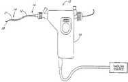
- FIG. 1is a schematic view of a device embodying the present invention
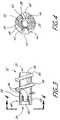
- FIG. 2is a partially sectioned side view of a distal end of the device of FIG. 1 , showing an embodiment of the cutter assembly;
- FIG. 3is a side view of the cutter of FIG. 2 ;
- FIG. 4is an end view of the cutter of FIG. 3 taken along the line 4 — 4 ;
- FIG. 5Ais a partially sectioned side view of another embodiment of the cutter and housing
- FIG. 5Bis a cross-sectional view of the cutter and housing of FIG. 5A taken along the lines 5 B— 5 B;
- FIG. 6is a partially sectioned side view of yet another cutter and housing
- FIG. 7is a partially sectioned side view of a further cutter and housing
- FIG. 8Ais a top perspective view of a serrated cutter configured in accordance with certain features, aspects and advantages of the present invention.
- FIG. 8Bis a side view of the serrated cutter of FIG. 8A ;
- FIG. 8Cis a top view of the serrated cutter of FIG. 8A ;
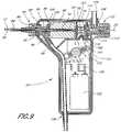
- FIG. 9is a sectioned side view of a control having features, aspects and advantages in accordance with the present invention.
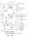
- FIG. 10Ais a schematic illustration of a pinch-valve switch in a position which interrupts an applied vacuum and interrupts power flow to a drive motor;
- FIG. 10Bis a schematic illustration of a pinch-valve switch in a position that applies the vacuum and interrupts power flow to the drive motor;
- FIG. 10Cis a schematic illustration of a pinch-valve switch in a position which applies the vacuum and allows power to flow to the drive motor;
- FIGS. 11are schematic illustrations of a representative motor control circuit in accordance with the present invention.
- FIG. 12is an enlarged partially sectioned side view of a cutter, housing and catheter assembly configured in accordance with certain aspects and advantages of the present invention.
- FIG. 13is a schematic view of a treatment process performed according to a first mode of off-set operation.
- FIG. 14is a schematic view of a treatment process performed according to a second mode of off-set operation.
- a surgical instrumentindicated generally by reference numeral 10 having features, aspects and advantages in accordance with the present invention is depicted therein.
- the illustrative surgical instrumentcomprises an elongate flexible tubular body 12 having a proximal end 14 and a distal end 16 .
- a control 18is preferably provided at or near the proximal end 14 of the tubular body 12 for permitting manipulation of the instrument 10 .
- the control 18advantageously carries electronic controls and indicators as well as vacuum controls as will be discussed below.
- the tubular body 12preferably has an elongate central lumen 20 .
- the tubular body 12has a cutter housing 21 for receiving a cutter 22 that may rotate therein.
- the illustrated cutter 22is coupled to the control 18 for rotation by way of an elongate flexible drive shaft 24 , as will be described below.
- the drive shaft 24may also be provided with an axially extending central lumen 26 for slidably receiving a guidewire 28 as will be understood by those of skill in the art.
- the cutter 22may also have a central lumen.
- the diameter of the guidewire 28is preferably in the range of about 0.010 inch to about 0.020 inch.
- the lengths of the guidewire 28 and the tubular body 12may be varied to correspond to a distance between a percutaneous access site and a lesion being treated.
- the guidewire 28 and the tubular body 12should be long enough to allow the cutter 22 of the present surgical instrument 10 to track along the guidewire 28 and reach a target occlusion while also allowing a proximal portion of the guidewire 28 to remain exterior to the patient for manipulation by the clinician (not shown).
- guidewireshaving lengths from about 120 cm to about 160 cm may be used, and the length of the tubular body 12 may range between about 50 cm and about 150 cm, as will be understood by those of skill in art.
- the length of the guidewire 28 and the tubular body 12may depend upon the location of the graft or other treatment site relative to the percutaneous or surgical access site.
- Suitable guidewires for coronary artery applicationsinclude those manufactured by Guidant or Cordis.
- the illustrated cutter 22includes a generally cylindrical sleeve shaped body 30 having a central lumen 32 ( FIG. 4 ).
- the cylindrical body 30 of the cutter 22generally has an external diameter of between about 0.035 inch and 0.092 inch. In one embodiment, the external diameter is approximately 0.042 inch.
- the body 30has a wall thickness between about 0.003 inch and about 0.010 inch. In one embodiment, the wall thickness is about 0.009 inch.
- the length of one embodiment of the present cutter 22 from proximal end 34 to distal end 36is approximately 0.096 inch but the length may vary from about 0.040 inch to about 0.120 inch or more, depending upon the intended use. In general, tip lengths of no more than about 0.100 inch are preferred; shorter tip lengths permit greater lateral flexibility and enable increased remote access as will be apparent to those of skill in the art.
- an end cap 38may be formed on the distal end 36 of the present cutter tip 22 .
- the cylindrical body 30may be machined to create an integral (i.e., one piece) end cap 38 .
- the end cap 38may have a thickness of approximately 0.007 inch; however, the end cap thickness may range from about 0.003 inch to about 0.020 inch.
- a discrete end cap 38may also be separately machined and attached.
- the end cap 38may be formed from a more lubricious material to reduce frictional contact between the guidewire 28 and the end cap 38 .
- Such an end capmay be attached in any suitable manner.
- the end cap 38preferably has an outside diameter that substantially corresponds to the outside diameter of the distal end 26 of the present cutter tip 22 .
- the end cap outside diametermay, however, substantially correspond to the inside diameter of the cylindrical body in some embodiments.
- the end cap 38may also have a centrally located aperture 39 .
- the aperture 39if present, preferably has a diameter of between about 0.013 inch and about 0.025 inch. In one embodiment, the aperture 39 has a diameter of approximately 0.022 inch. Desirably, the aperture 39 may accommodate a guidewire 28 or allow fluids to flow therethrough.
- the cutter 22may have a machined or otherwise integrally formed radially inwardly extending annular flange 41 (see FIG. 6 ). It is also anticipated that aspects of the present invention may also be practiced without employing an end cap or inwardly extending annular flange 41 .
- the flange 41may extend fully around the circumference of the cutter 22 or may have portions removed such that the annular flange 41 is actually a series of inwardly projecting tabs. Additionally, an outside distal edge of the end cap 38 or annular flange 41 is desirably broken, chamfered or rounded such that any sharp edge resulting from manufacturing may be removed, and such that the end cap may be rendered substantially atraumatic.
- a connector portion 40is preferably provided at or near the proximal end 34 of the illustrated cutter 22 for securing the cutter 22 within the cutter housing 21 such that the cutter may rotate therein.
- the connector portion 40may be a mechanical, self-locking method to secure the rotating cutter 22 within the cutter housing 21 and to guard against undesired axial movement of the cutter 22 relative to the housing 21 .
- axial movement of the cuttermay be accommodated within the housing 21 , and even within the tubular body 12 , as will be discussed below in more detail.
- the connector portion 40retains the cutter tip 22 within the cutter housing 21 and may reduce the need for such multiple redundancies.
- the connector portion 40may take various forms.
- the connector portion 40generally comprises two outwardly extending radial supports, such as a set of wedge-shaped flanges 42 .
- the flanges 42may be formed by removing material from an annular circumferential flange at the proximal end 34 of the cutter 22 .
- the flanges 42may be formed into the illustrated wedge-shape, although other shapes may also be desirable.
- the flanges 42may also be bent from a proximal extension of the wall of tubular body 30 , or adhered or otherwise secured to the proximal end 34 of the cutter 22 .
- the cutter 22 and flanges 42may be cast or molded using any suitable method dependent upon the material chosen.
- the flanges 42may alternatively be connected to tubular body 30 at a point in between the proximal end 34 and the distal end 36 of the cutter tip.
- flanges 42may be utilized, as will be apparent to those of skill in the art.
- the flanges 42should be evenly distributed around the circumference of the cutter 22 to improve balance during rotation of the cutter 22 .
- three flanges 42would preferably extend radially outward from the cylindrical wall of the body 30 on approximately 120° centers.
- four outwardly extending radial flanges 42would preferably be located on approximately 90° centers.
- the outwardly extending radial supports 42are also formed by removing material from an annular circumferential flange at the proximal end of the cutter 22 .
- the supports 42are attached to the balance of the cutter 22 with tangs 43 that are carved from the cutter 22 when the supports 42 are formed. In this manner, the tangs 43 do not require the slots that form the arms described above.
- a combination of the slots and arms and the tangs without slotsmay also be used to attach the flange 42 to the cutter 22 .
- the tangs 43preferably are between about 0.010 inch and about 0.050 inch in length.
- the tangs 43are about 0.015 inch long. In one embodiment, the tangs are about 0.25 inch long. The tangs also have a width between about 0.010 inch and about 0.050 inch. In a presently preferred embodiment, the tangs have a width of about 0.020 inch.
- the illustrated connector portion 40has an outside diameter taken about the opposing flanges 42 of approximately 0.071 inch.
- the outside diametermay range from about 0.057 inch to about 0.096 inch in a device intended for coronary artery applications.
- the thickness of the flanges 42 in the axial directioni.e., the dimension normal to the increase in diameter resulting from the flanges
- an outside diameter defined about the flanges 42may be selected to cooperate with the inside diameter of an annular retaining race or groove 54 in the housing 21 , discussed below, to axially retain the cutter 22 while permitting rotation of the cutter 22 relative to the housing 21 .
- the thickness of the flanges 42 and the axial width of the retaining groove 54also are generally designed to either allow axial movement of the cutter 22 within the housing 21 or to limit or eliminate substantial axial movement of the cutter 22 within the housing 21 , as is discussed below.
- each illustrated flange 42is preferably attached to the cutter 22 by a spring arm 43 .
- Each arm 43is defined by two longitudinally extending slots 44 which are formed in the cylindrical wall of the body 30 adjacent each flange 42 .
- the slots 44are preferably about 0.005 inch in width; however the width may range from approximately 0.001 inch to approximately 0.025 inch.
- the slots 44 of the present cutter 22are also generally at least about 0.025 inch in axial length along the longitudinal axis of the body 30 .
- the slots 44 of the present cutter 22can be varied in axial length to vary the length of the cantilevered arm 43 that connects the flanges 42 to the cutter 22 .
- the slots 44 , and the arm 43 defined between the slots 44 , and the tangsallow radial inward compression of the flanges 42 and spring arms 43 , or tangs, to ease assembly of the cutter 22 within the cutter housing 21 as described below.
- the cutter 22is made of a material having an adequate spring constant as will be understood by those of skill in the art.
- the cutter 22is made from a medical grade stainless steel alloy.
- the chosen materialpreferably has characteristics including the ability to allow the cantilevered spring arm 43 to deflect radially inwardly an adequate distance over the length of the arm 43 without exceeding the elastic limit of the material (i.e., the deflection is an elastic deformation).
- elastic deformationsallow structures to deflect and substantially return to their initial shape or position. For instance, special hardening methods may be used to maintain the elasticity of the selected material in the deflection range necessary for a specific application.
- the cutter 22is snap fit into the cutter housing 21 .
- the arms 43may be deflected radially inward such that the cutter 22 may be inserted into the cutter housing 21 through an aperture or lumen having a smaller ID than the inside diameter of the retaining groove 54 of the cutter housing 21 .
- the cutter 22is inserted from the distal end of the housing 21 and slid proximally through the housing 21 until the flanges 42 snap outward into the race 54 .
- the cutter 22will be retained in this housing even if it separates from its drive element 24 .
- the arms 43substantially return to their original, relaxed positions within the retaining groove 54 the cutter housing 21 following installation. It should be appreciated that the arms 43 may also be maintained under a slight bending stress (i.e., the inside diameter of the race 54 may be smaller than the outside diameter about the relaxed flanges 42 ) if desired.
- the elementmay include a thread 46 that extends along a portion of the exterior surface of the body 30 of the present cutter 22 .
- the thread 46preferably extends distally from a location on the body 30 that is distal to the connector 40 .
- the thread 46may be manufactured using any suitable technique well known to those of skill in the art.
- the major diameter of the thread 46is approximately 0.0681 inch.
- the major diameter of the present thread 46may range from about 0.050 inch to about 0.130 inch or otherwise, depending upon both the inner diameter of the cutter housing and the intended clinical application.
- the thread 46 of the foregoing embodimenthas a pitch of approximately 0.0304 inch and is desirably helical. The pitch may range from about 0.005 inch to about 0.060 inch, and may be constant or variable along the axial length of the cutter 22 .
- the thickness of the present thread 46 in the axial directionis approximately 0.008 inch; however, the thickness may range from about 0.003 to about 0.05, and may be constant or variable along the length of the thread 46 .
- the cutters 22may also have a generally spiral helix thread.
- the thread 46extends approximately two complete revolutions around the cylindrical body 30 .
- the thread 46may be a continuous radially outwardly extending ridge as illustrated, or may comprise a plurality of radially outstanding blades or projections preferably arranged in a helical pattern.
- the thread 46may extend as little as about one-half to one full revolution around the cutter body 30 , or may extend as many as 21 ⁇ 2 or 3 or more full revolutions around the circumference of the body 30 , as is discussed more below.
- optimization of the length of the thread 46may be accomplished through routine experimentation in view of the desired clinical objectives, including the desired maneuverability (i.e., tractability through tortuous anatomy) and the length of the cutter 22 , as well as the nature of the cutting and/or aspiration action to be accomplished or facilitated by the cutter 22 .
- the present cutter 22is illustrated and described as having a single thread, one skilled in the art will appreciate that the cutter 22 may also have multiple threads, a discontinuous thread or no threads.
- the thread 46 illustrated thereinis a constant pitch and varies in cross-section along its length from a relatively low profile at the distal end 36 to a relatively higher profile at the proximal end 34 of the cutter tip 22 .
- Such a ramped thread 46improves performance when the catheter encounters more dense obstructive material.
- the major diameter of the distal lead 47 of the thread 46is smaller than the major diameter of the thread along the more proximal portions of the cutter shaft 30 . It is anticipated that the pitch of the thread 46 may also vary along with the profile of the thread 46 to alter the clinical effects accomplished.
- the pitch of the thread 46may also be varied along the axial length of the cutter body 30 . Varying the pitch allows a modified function at different points along the axial length of the cutter 22 , such as a greater axial thread spacing at the distal end 36 of the cutter 22 to engage material and a relatively closer axial spacing of the threads at the proximal end 34 of the cutter 22 for processing the material.
- the pitchmay range from about 0.010 inch at the distal end to about 0.080 inch at the proximal end.
- the pitch at the distal end 36is approximately 0.034
- the pitch at the proximal end 34is approximately 0.054, and the pitch varies continuously therebetween.
- the maximum and minimum pitch, together with the rate of change of the pitch between the proximal end 34 and the distal end 36can be optimized through routine experimentation by those of skill in the art in view of the disclosure herein.
- the ramped thread diameterresults in a distal portion 36 of the cutter 22 that can extend distally beyond the cutter housing 21 and a proximal portion 34 of the cutter tip 22 that will be retained within the cutter housing 21 .
- the distal portion 45 of the thread 46may have its leading edge broken, chamfered or rounded to remove a sharp comer or edge. By eliminating the sharp comer or edge, the risk of accidental damage to the patient is reduced.
- the distal edge of the cylindrical body 30 and the flanges 42may also be broken, chamfered or otherwise rounded to eliminate or reduce sharp edges.
- the outside diameter of the thread 46 in this embodimenthas a close sliding fit with the inside diameter, or inner wall, of the cutter housing 21 .
- the atheromatous materialwill be avulsed by the threads 46 , fed further into the housing 21 toward the flanges 42 and chopped or minced by the flanges 42 .
- a stationary member(not shown) or a set of stationary members (not shown) may be positioned such that the rotating flanges 42 and the stationary member or members (not shown) effect a shearing action. The shearing action breaks up the strands into shorter sections, which are less likely to clog the instrument, as described below.
- the flanges 42may be provided with sharply chamfered leading or trailing edges to alter their cutting action, if desired.
- annular spacebetween the outside diameter of the thread 46 and the inside diameter of the cutter housing 21 .
- an annular spaceis provided for material to pass through the cutter housing 21 without being severed by the thread 46 of the cutter tip 22 .
- Thismay be utilized in conjunction with vacuum, discussed below, to aspirate material into the atherectomy device without the necessity of complete cutting by the thread 46 or flanges 42 . This may be advantageous if the rate of material removal effected by aspiration is higher than the rate at which material removal may occur with the thread 46 engaging such material.
- the rotational atherectomy device 10may more readily aspirate certain lesion morphologies, such as those including portions of calcified plaque, if the thread 46 is not required to cut all the way through the aspirated material.
- the desired radial distance between the thread 46 and the inside wall of the cutter housing 21will be between about 0.0001 inch and about 0.008 inch, to be optimized in view of the desired performance characteristics of the particular embodiment.
- the cutting function of the thread 46 , or the thread 46 itselfmay be deleted entirely, so that cutting occurs by the flanges or cutting blocks 42 and/or stationary members (not shown) in cooperation with the aspiration provided by a vacuum source.
- Interventions for which an atraumatic distal tip is desiredcan be well served by an atraumatically tipped cutter 22 , as illustrated in FIG. 7 .
- the blunt tip cutter 22preferably has a bulbous or rounded tip 23 that extends from the distal end of the cutter 22 .
- the tip 23preferably has a radially symmetrical configuration such that upon rotation it presents a smooth, atraumatic surface for tissue contact. Viewed in side elevation, such as in FIG.
- the tip 23may have a generally hemispherical, oval, elliptical, aspheric or other smooth curve on its radial surface with either a curved or truncated (i.e., flat) distal surface.
- the shape of the tip 23may be varied to achieve desirable effects on the catheter crossing profile or on soft atheromas, etc.
- the tip 23advantageously minimizes the possibility of traumatic contact between the healthy wall of the vessel and the thread 46 or other cutting element.
- the outside diameter of the tip 23may range from the outside diameter of the cutter body 30 to the outside diameter of the cutter housing 21 . Diameters greater than the housing 21 may also be used, but diameters smaller than the housing 21 facilitate a smaller crossing profile of the instrument 10 .
- the axial length of the tip 23may be varied to suit the intended application, but will generally be within the range of from about 0.050 inch to about 0.100 inch in a coronary artery application.
- the outside surface of tip 23may be provided with surface texturing or treatments.
- the surface texturing or treatmentsmay be formed by abrasive coating (i.e., coating the tip with diamond particles), acid etching or any other suitable method.
- the texture or treatmentsmay be on the distal surface or the lateral surfaces or both such that a two-stage interaction with the encountered materials may occur.
- the tipcan be used for grinding or otherwise remodeling the encountered materials.
- an abrasive distal surfacecan be used to cut through calcified plaque, while a smooth radial surface can compress soft material against the vessel wall to facilitate acceptance into the helical thread 46 of the cutter 22 .
- Varying the distance between the distal end 47 of the thread 46 and the proximal end of the tip 23 , as well as varying its geometry,can allow adjustments to the cutter aggressiveness.
- the thread 46may extend up to the proximal edge of the tip 23 and allow early engagement of the encountered materials relative to a cutter 22 having a length of unthreaded shaft between the proximal edge of the tip 23 and the distal end 47 of the thread 46 .
- the tip 23can be integrally formed with the cutter tip 22 , such as by machining techniques known in the art. Alternatively, it can be separately formed and secured thereto, such as by soldering, adhesives, mechanical interference fit, threaded engagement and the like.
- the tipcan be machined from a suitable metal or molded or otherwise formed from a suitable polymeric material such as polyethylene, nylon, PTFE or others known to those of ordinary skill in the art.
- the cutter tip 22itself may be machined such that the distal facing end is serrated or discontinuously formed.
- the discontinuous threadmay comprise a number of inclined surfaces forming distally facing teeth. In such cutters, the cutter is more aggressive in the forward direction.
- a cutter tip 22may have serrations 57 formed along the distal end 47 of the thread 46 .
- the serrationsmay also be positioned on an extended nose portion (not shown) of the cutter.
- the serrations 57preferably are formed to extend outward radially from the center axis of the cutter 22 .
- the serrations 57are formed in a straight line, the serrations 57 may also be arcuate in shape to form a sickle-shaped cutting surface.
- the illustrated serrations 57preferably have a depth of between about 0.0005 inch and about 0.0040. More preferably, the serrations 57 are about 0.0020 deep.
- the serrations 57also preferably are formed with a sloping face 59 that is at an angle 1 of between about 45° and about 85° with a longitudinal plane that extends through the axis of rotation. In a presently preferred arrangement, the sloping face extends at an angle of about 60° relative to the same plane.
- the run of the sloping face 59is preferably between about 0.0020 inch and about 0.0050 inch. In the preferred arrangement, the run is about 0.0035 inch in length.
- the serrations in the illustrated cutterextend over only a forward facing portion 45 of the distal end 36 of the cutter 22 ; however, it is anticipated that the cutter 22 may also comprise a serrated thread that extends the entire length of the thread 46 .
- FIG. 6illustrates a cutter 22 arranged to float axially within the housing 21 .
- the cutter 22is provided with an anti-locking thread design.
- the thread 46may be configured such that it cannot jam within the housing 21 at either extreme of axial travel.
- Such a configurationmay involve having a minimum thread major diameter which is greater than the diameter of the opening in the distal end of the device 10 or having a pitch which is less than the thickness of the ring flange 41 formed at the distal tip of the cutter housing 21 .
- Other configurationsmay also be readily apparent to those of ordinary skill in the art.
- the axial travel and the thread designdesirably cooperate to allow the cutter 22 to self-adjust to digest soft fibrous material.
- the housing 21may conveniently be assembled from two pieces, to entrap the cutter 22 therein. The two pieces are then laser-welded or otherwise secured together. In one embodiment, the housing 21 may be split longitudinally, the cutter 22 inserted, and the two pieces may then be secured together. In another presently preferred embodiment, the two pieces may split the housing 21 into a distal component and a proximal component (see FIG. 6 ). The two components may be assembled to trap the cutter 22 therein and may then be laser-welded or otherwise secured together.
- Such assembliesallow for the cutter 22 to be captured within the cutter housing 21 as well as allow for certain relatively loose manufacturing tolerances for the cutter 22 and the cutter housing 21 such as will reduce manufacturing costs. Such assemblies also enable better fits because the flanges 42 require less travel (i.e., the flanges 42 do not require deflection for insertion into the housing 21 ).
- the illustrated housing 21internally may be a stepped cylinder having a proximal end 50 and the distal end 52 .
- an annular bearing surface 48(see FIG. 6 ) provides a proximal limit of travel for the flanges 42 on cutter 22 .
- the annular bearing surface 48may be formed within the cutter housing 22 (as illustrated in FIG. 6 ) or within the tubular body 12 (not shown).
- the internal diameter of the distal portion 52 of the cutter housing 21is approximately 0.0689 inch and may range from about 0.050 inch to about 0.150 inch.
- the proximal end 50 of the present cutter housing 21preferably has an internal diameter of approximately 0.0558 inch.
- the internal diameter 50 of the proximal end of the present cutter housing 21may range from about 0.035 inch to about 0.130 inch.
- the cutter housing 21may be provided with a radially inwardly extending retaining lip, such as flange 41 in FIG. 6 , sized and configured such that the cutter 22 is captured within the cutter housing 21 and such that the cutter 22 cannot screw itself out of its captured position within the cutter housing 21 .
- the exterior diameter of the distal end 52 of the cutter housing 21 in one embodimentis approximately 0.0790 inch; however, the distal exterior diameter may range from about 0.039 inch to about 0.150 inch depending upon cutter design and the intended clinical application.
- the distal portion 52 of the cutter housing 21 in the illustrated embodimentis about 0.117 inch in length but the length may vary from about 0.020 inch to about 0.50 inch.
- the outside diameter of the proximal portion 50 of the cutter housing 21may be less than the diameter of the distal portion 52 to produce an annular shoulder 51 to limit concentric proximal advance of the proximal section within the tubular body 12 .
- the proximal section of the housing 50extends axially for approximately 0.09 inch but its length may vary as will be understood by those of skill in the art.
- the cutter housing 21may be integrally formed or separately formed and secured to the distal end 16 of the tubular body 12 in accordance with any of a variety of techniques which will be known to those of skill in the art.
- the concentric overlapping joint illustrated in FIG. 2can be utilized with any of a variety of secondary retention techniques, such as soldering, the use of adhesives, solvent bonding, crimping, swaging or thermal bonding.
- an outer tubular sleeve(not shown) may be heat shrunk over the joint between the cutter housing 21 and the tubular body 12 .
- the proximal portion 50 of the cutter housing 21desirably does not block a portion of the annual recess defined between the central lumen 20 and the outer surface of the drive element 24 . It is anticipated that this style of connection can be utilized with any of the cutter housing features described herein and that the cutter housing 21 may be provided with an internal stop to limit axial displacement of the cutter housing 21 relative to the distal end 16 of the tubular body 12 .
- the retaining race 54in one embodiment is approximately 0.0015 inch deep relative to the inner diameter of the distal section 52 and may range in depth from about 0.0005 inch to about 0.020 inch.
- the retaining race 54 in the illustrated embodimentis about 0.0135 inch in axial width; however, as one skilled in the art will readily appreciate, the race width may be varied and still accomplish its retention function as is discussed further below.
- the race 54may be located proximally, or extend proximally, of the cutter housing 21 such that the cutter 22 may be retracted within the tubular body 12 .
- the retaining race 54cooperates with the flanges 42 of the present cutter 22 to retain the cutter 22 within the cutter housing 21 as described in detail above.
- the flanges 42provide a bearing surface for the cutter 22 to facilitate rotational movement of the cutter 22 relative to the housing 21 .
- the cutter 22may be substantially restrained from axial movement within the cutter housing 21 .
- the race 54may be larger in axial width relative to the thickness of the flanges 42 to allow axial movement of the cutter 22 within the cutter housing 21 or even into the tubular body 12 as discussed above.
- the distal extremity of the illustrated cutter 22may be approximately aligned with the distal extremity of the cutter housing 21 .
- the length of the cutter housing 21 distal of the retaining groove 54substantially corresponds to the length of the portion of the of the cutter 22 which extends distally of the distal surfaces of flanges 42 .
- the distal end 36 of the cutter 22may alternatively extend beyond, or be recessed within, the distal end 52 of the cutter housing 21 (i.e., the embodiment of FIG. 7 ).
- the cutter 22may be arranged for selective extension and retraction relative to the cutter housing 21 , the benefits of which are described below.
- FIGS. 5A and 5BAnother cutter 60 and associated cutter housing 70 are illustrated in FIGS. 5A and 5B .
- the cutter 60embodies many of the same features as the cutter 22 described above, like elements will generally be called out by new reference numerals for ease of discussion. It should be recognized, however, that any of the features, aspects or advantages of the cutter 22 described above and the cutter 60 described below may be easily interchanged by one of ordinary skill in the art.
- the cutter 60is preferably symmetrical about the rotational axis having a body 61 with an annular retention structure, such as a retaining race 62 , located near the body's proximal end 64 .
- the retaining race 62 , or connector portion, in the illustrated embodimentis about 0.007 inch deep, and about 0.008 inch wide, although both dimensions can be varied as may be desired and still achieve the desired retention function, as will be readily recognized by one with skill in the art.
- Proximal to the retaining race 62the outside diameter of the body 61 is rounded or tapers from about 0.04 inch to about 0.036 inch. Preferably, all edges are broken, chamfered or otherwise rounded to ensure burr free and dull comers and to facilitate assembly.
- the cutter 60may also have a thread 66 similar to that described above.
- the cutter 60is preferably snap fit into the cutter housing 70 by inserting the cutter 60 into the distal end 74 of the cutter housing 70 .
- the cutter housing 70is preferably similar to that described above with the exception that the retaining race 54 of the first housing is replaced by a set of inwardly extending radial retaining members 72 .
- the present cutter housing 70has three retaining members 72 , preferably circumferentially symmetrically distributed (i.e., on about 120 ⁇ centers).
- the number, size and shape of the retaining memberscan vary; at least two will generally be used to achieve opposition, and embodiments having 3, 4, 5 or more may be readily utilized. It is possible, however, to utilize a single retaining member in some applications such that the single retaining member operates as a stationary cutter member either with or without a set of cutter blocks ( 42 in the embodiments described above).
- the retaining members 72are sized and configured to allow deflection within the elastic range such that the retaining members 72 may be deflected and inserted into the race 62 as discussed below.
- this snap fit configurationadvantageously enables the cutter 60 to be retained in the cutter housing 70 even if the cutter 60 separates from the driving element (not illustrated).
- the retaining members 72may serve the added function of stationary cutting members. As such the retaining members 72 may be sized accordingly.
- the illustrated retaining members 72are about 0.007 inch thick in the axial direction; however, one skilled in the art will appreciate that the thickness can range from about 0.003 inch to about 0.030 inch or otherwise depending upon material choice and the desired degree of axial restraint.
- the retaining members 72extend about 0.007 inch inward from the interior wall of the cylindrical cutter housing 70 .
- the retaining member 72 lengthcan vary, however, depending upon the desired dimensions of the cutter housing 70 and the cutter 60 .
- the side edges 73 of the retaining members 72may be provided with a radius such that the radial interior and exterior ends are wider than the central portion.
- the stationary retaining members 72may alternatively be provided with a convex radius (not shown) to form a smoothly transitioning profile.
- the retaining members 72are provided to engage within the retaining race 62 of the cutter 60 .
- the retaining members 72 and the race 62may be sized and configured such that the cutter 60 is either substantially restrained from axial movement relative to the cutter housing 70 or some axial travel is allowed between the two components.
- the retaining members 72may also provide a bearing surface for the rotational movement of the cutter 60 relative to the cutter housing 70 .
- the race 62 of the cutter 60desirably rides on the ends of the retaining members 72 such that the retaining members 72 provide bearing surfaces at their inner most edges and allow the cutter 60 to be rotated relative to the housing 70 .
- the distal end 65 of the cutter 60may be approximately flush with the distal end 74 of the cutter housing 70 .
- the distal end 65 of the cutter 60may extend distally from or may be slightly recessed within the distal end 74 of the cutter housing 70 by as much or more than is shown in FIG. 5A .
- the cutter 60may be selectively advanced or retracted relative to the cutter housing 70 , enabling advantages that are described below.
- a flexible drive shaft 24may be firmly secured within an axial bore 32 of the cutter 22 .
- the cutter 22may be secured to the flexible drive shaft 24 by any of a variety of ways such as crimping, swaging, soldering, interference fit structures, and/or threaded engagement as will be apparent to those of skill in the art.
- the flexible drive shaft 24could extend axially through the cutter 22 and be secured at the distal end 36 of the cutter 22 .
- the cutter 22 and the cutter housing 21may be designed so that the cutter 22 may be positioned within the cutter housing 21 in a manner that allows axial movement of the cutter 22 relative to the cutter housing 21 .
- Controllable axial movement of the cutter 22may be accomplished in a variety of ways, to achieve various desired clinical objectives. For example, in either of the embodiments illustrated in FIGS. 2 and 5 a , a minor amount of axial movement can be achieved by increasing the axial dimension of the annular recesses 54 , 62 with respect to the axial dimension of the flanges 42 , or retaining members 72 .
- the annular proximal stop 48( FIG.
- the proximal stop 48can be eliminated entirely such that the entire inside diameter of the tubular body 12 is able to accommodate the flanges 42 or their structural equivalent, or the outside diameter of the thread 46 , depending upon the embodiment. Limited axial movement can also be accomplished in the manner illustrated in FIGS. 6 and 7 , as will be appreciated by those of skill in the art.
- relatively minor degrees of axial movementsuch as on the order of about one or two millimeters or less may be desirable to help reduce the incidence of clogging and also reduce trauma, such as by the distal cutting tip pressing against a vessel wall.
- Minor axial movabilitycan also help compensate for differential elongation or compression between the tubular body 12 and the drive shaft 24 .
- a greater degree of axial movabilitymay be desirable in embodiments in which the cutter 22 may be controllably extended partially beyond the housing 21 such as to improve engagement with hard obstructive material. Retraction of the cutter 22 within the cutter housing 21 may be desirable during insertion of the device 10 , to minimize trauma to the vascular intima during positioning of the device 10 . The cutter 22 may thereafter be advanced distally on the order of 1 to 3 or 5 millimeters beyond the distal end 52 of the housing 21 , such as to engage obstructive material to be drawn into the cutter housing 21 .
- More significant proximal retraction of the cutter 22 within the housing 21may be advantageous during positioning of the atherectomy catheter.
- one of the limitations on positioning of a transluminal medical device within tortuous vascular anatomyis the lateral flexibility of the distal portion of the device. Even if the outside diameter or crossing profile of the device is small enough to reach the stenotic region, the device still must have sufficient pushability and sufficient lateral flexibility to navigate the tortuous anatomy.
- the rotatable drive shaft 24can significantly increase the rigidity of the catheter.
- the drive shaft 24 and the cutter 22may be proximally withdrawn within the tubular housing 12 to provide a relatively highly flexible distal catheter section that is capable of tracking a guidewire 28 through tortuous vascular anatomy.
- the cutter 22 and the drive shaft 24may be distally advanced through the tubular body 12 and into position at the distal end 16 . In this manner, the rotational atherectomy catheter can be positioned at anatomical locations that are not reachable if the drive shaft 28 and housing 21 at the distal end 16 of the tubular body 12 are advanced as a single unit.
- the cutter 22is preferably proximally retractable from the distal end 52 of the cutter housing 21 by a distance sufficient to permit the outer tubular body 12 and cutter housing 21 to be positioned at the desired treatment site.
- the distance between the distal end 52 of the cutter housing 21 and the retracted cutter 22is generally be within the range of from about 5 cm to about 30 cm and preferably at least about 10 cm. Proximal retraction of the cutter 22 over distances on that order will normally be sufficient for most coronary artery applications.
- the flexible drive shaft 24is preferably a hollow, laminated flexible “torque tube” such as may be fabricated from an inner thin-wall polymeric tubing, an intermediate layer of braided or woven wire, and an outer polymeric layer.
- the torque tubecomprises a polyimide tube having a wall thickness of about 0.004 inch, with a layer of braided 0.0015 inch stainless steel wire embedded therein.
- the laminated constructionadvantageously produces a tube with a very high torsional stiffness and sufficient tensile strength, but which is generally laterally flexible. However, depending upon the desired torque transmission, diameter and flexibility, any of a variety of other materials and constructions may also be used.
- the drive shaft 24should have sufficient torsional rigidity to drive the cutter 22 through reasonably foreseeable blockages. It is also recognized that in some applications, the drive shaft 24 may be a wire or other solid construction such that no inner lumen 26 extends therethrough.
- the outside diameter of one embodiment of the present hollow flexible drive shaft 24is approximately 0.032 inch, but may range between about 0.020 inch and about 0.034 inch or more.
- the diameter of the flexible drive shaft 24may be limited by a minimum torsional strength and a guidewire diameter, if a guidewire 28 is present, at the low end, and maximum permissible catheter outside diameter at the high end.
- a hollow drive shaft 24allows the device 10 to be advanced over a conventional spring-tipped guidewire 28 , and preferably still leaves room for saline solution, drugs or contrast media to flow through the lumen 26 of the drive shaft 24 and out of the distal opening 39 on the cutter 22 .
- the internal diameter of the present hollow flexible drive shaft 24is thus partially dependent upon the diameter of the guidewire 28 over which the flexible drive shaft 24 must track.
- the internal diameter of the guidewire lumen 26 in one embodiment of the present hollow flexible drive shaft 24intended for use with a 0.018 inch diameter guidewire, is approximately 0.024 inch. Because the flexible drive shaft 24 preferably extends between the control 18 and the cutter 22 , the length of the present hollow flexible drive shaft 24 should be sufficient to allow the cutter assembly to reach the target location while also allowing adequate length outside of the patient for the clinician to manipulate the instrument 10 .
- the lumen 20 of the assembled device 10is thus an annular space defined between the inside wall of the flexible tubular body 12 and the outside of the flexible drive shaft 24 .
- This lumen 20may be used to aspirate fluid and material from the cutter.
- sufficient clearanceis maintained between the tubular body 12 and the rotating drive shaft 24 to minimize the likelihood of binding or clogging by material aspirated from the treatment site.
- the cross-sectional area of the lumen 20is preferably maximized as a percentage of the outside diameter of the tubular body 12 . This permits an optimization of lumen cross-sectional area which maintains a minimal outside diameter for tubular body 12 , while at the same time permitting an acceptable flow rate of material through the aspiration lumen 20 , with minimal likelihood of clogging or binding which would interrupt the procedure.
- Cross-sectional area of the aspiration lumen 20thus may be optimized if the drive tube 24 is constructed to have relatively high torque transmission per unit wall thickness such as in the constructions described above.
- the outside diameter of tubular body 12is about 0.080 inch, the wall thickness of tubular body 12 is about 0.008 inch, and the outside diameter of the drive shaft 24 is about 0.031 inch.
- Such a constructionproduces a cross-sectional area of the available aspiration portion of central lumen 20 of about 0.00245 square inch. This is approximately 50% of the total cross-sectional area of the tubular body 12 .
- the cross-sectional area of the lumen 20is at least about 25%, more preferably at least about 40%, and optimally at least about 60% of the total cross-sectional area of the tubular body 12 .
- the tubular body 12may comprise any of a variety of constructions, such as a multi-layer torque tube. Alternatively, any of a variety of conventional catheter shaft materials such as stainless steel, or single layer polymeric extrusions of polyethylenes, polyethylene terephthalate, nylon and others well known in the art can be used.
- the tubular body 12is a PEBAX extrusion having an outside diameter of approximately 0.090 inch.
- the outer diametercan vary between about 0.056 inch for coronary vascular applications and about 0.150 inch for peripheral vascular applications.
- the foregoing tubular body 12desirably has a wall thickness of at least about 0.005 inch. The wall thickness can, however, be varied depending upon materials and design.
- the distal end of the tubular body 12may be affixed to the proximal end 50 of the cutter housing 21 as shown in FIG. 2 and described above.
- the proximal end of the tubular body 12may be affixed to the control 18 as described below.
- a reinforcing tube 80is desirably provided to reduce the likelihood of a failure at that location due to bending forces.
- the reinforcing tube 80may extend from the control unit 18 along a proximal portion of the tubular body 12 .
- the reinforcing tube 80preferably extends distally over the tubular body 12 at least about 3 cm and more preferably about 6 cm, and desirably comprises silicone or other conventional biocompatible polymeric material.
- the illustrated reinforcing tube 80provides support to avoid over bending and kinking at the proximal end of the drive shaft 24 .
- the reinforcing tube 80may be fastened to the control 18 such as by interference fit over a snap tip assembly 82 through which the flexible drive shaft 24 and tubular body 12 enter the control 18 .
- the reinforcing tube 80advantageously envelops a proximal portion of the tubular body 12 .
- the flexible drive shaft 24 and the tubular body 12operatively connect the cutter 22 and the cutter housing 21 to the control 18 of the illustrated embodiment.
- the tubular body 12 and the drive shaft 24enter the control 18 through the snap tip assembly 82 .
- the snap tip assembly 82may be provided with a connector, such as a hub 84 , having a central lumen in communication with a vacuum manifold 86 .
- the tubular body 12may be connected to the hub 84 .
- the hub 84may snap onto and seal a vacuum manifold 86 to the hub 84 and, consequently, to the tubular body 12 .
- the hub materialtherefore, desirably provides long-term memory for snap-fit tabs that secure this part to the rest of the assembly.
- the presently preferred hub 84is injection molded using a white acetyl such as Delrin.
- the hub 84may be rotatable, and may enable the operator to rotate the tubular body 12 relative to the control 18 such that the operator, or clinician, may steer the tubular body 12 without having to move the control 18 along with the tubular body 12 . Friction to limit this rotation may be provided by a bushing 87 that is compressed against the hub 84 in the illustrated embodiment.
- the tubular body 12may be reinforced internally where it passes through the hub 84 , such as by a thin-wall stainless steel tube (not shown) that extends through and is bonded to the hub 84 .
- a good rotational couplingis desired between the tubular body 12 and the hub.
- a portion of the hub boremay be hexagonal shaped, or formed in any other non-circular shape which corresponds to a complementary shape on the tube to enhance the rotational connection between the hub bore and the tube (not shown).
- Epoxy or other adhesivesmay also be injected into a space around the stainless steel tube to help prevent the stainless steel tube (not shown) from rotating relative to the hub 84 .
- the adhesivealso advantageously secures the two components such that the tube (not shown) is less likely to axially pull out of the hub 84 .
- the vacuum manifold 86is preferably fastened to a vacuum hose 88 at one outlet and to a motor 90 at a second outlet.
- the hub-end of the vacuum manifold 86desirably houses two silicone rubber O-rings 85 that function as dynamic (rotatable) seals between the manifold 86 and the steel tube (not shown) which extends through the hub 84 .
- the opposite end of the manifold 86near the proximal end of the drive tube 24 , preferably contains a pair of butyl rubber fluid seals 94 . These dynamic fluid seals 94 may be lubricated with silicone grease.
- the two fluid seals 94are mounted back-to-back, with their lips pointing away from each other.
- the distal seali.e., closest to the cutter 22
- the proximal seali.e., closest to the motor 90
- the vacuum manifold 86may be connected to the motor 90 through use of a threaded motor face plate 100 .
- the vacuum manifold 86is preferably threaded onto the face plate 100 but may be connected in any suitable manner.
- the face plate 100may be attached to the output end of the motor 90 by a threaded fastener 102 .
- the presently preferred motor 90is a modified 6-volt direct-current hollow-shaft, 22 mm outside diameter motor built by MicroMo.
- poweris transmitted from the motor 90 to the flexible drive shaft 24 by a length of medium-wall stainless steel tubing that is preferably adhesively-bonded to the drive shaft 24 .
- the tubingforms a transfer shaft 107 and is preferably coated on the outer surface with approximately 0.001 inch of Type-S Teflon.
- the Teflon-coated, exposed ends of the rigid drive shaft, or transfer shaft 107provide a smooth wear-surface for the dynamic fluid seals discussed above.
- the transfer shaft tubingmay be hypodermic needle stock measuring approximately 0.036 inch inside diameter by 0.053 inch outside diameter, before coating.
- the transfer shaft 107desirably is slip fit through the approximately 0.058 inch inside diameter of the hollow motor shaft, and desirably extends beyond the length of the motor shaft in both directions.
- the slip fitadvantageously accommodates axial sliding movement of the transfer shaft 107 relative to the motor 90 and the balance of the instrument 10 .
- axial movabilitymay be accommodated.
- the drive shaft 24is advantageously capable of axial movement relative to the motor 90 as described above. Controlled axial movement of the drive shaft 24 , and ultimately the cutter 22 and its connected components, is desirable regardless of the mechanical connection allowing such movement.
- the movementallows the cutter 22 and, in some embodiments, the drive shaft 24 to be withdrawn proximally during placement of the catheter sheath, or tubular body 12 , in the vasculature. Following positioning, the cutter 22 may then be advanced forward into a cutting position.
- Such a configurationallows increased maneuverability and flexibility during positioning and easier tracking through the vasculature. This configuration also allows for easier sterilization of the outer tubular body 12 in a compact coiled package.
- such relative axial movement of the cutter 22 and the tubular body 12is not necessary for utilization of various other aspects and advantages of the current invention.
- a small drive plate 103bonded to the rear end of the transfer shaft 107 , advantageously couples with a drive sleeve 105 that is attached to the approximately 0.078 inch outside diameter motor shaft 92 .
- the drive plate 103may be any of a number of geometric configurations.
- the drive plate 103is a rotationally symmetrical shape having a central aperture although other configurations may also be used. The symmetry facilitates rotational balancing.
- the drive plate 103is square with a central aperture, triangular with a central aperture, or circular with a central aperture, with a connecting member to tie the drive plate to the drive sleeve with a reduced likelihood of slippage.
- the drive plate 103 and the drive sleeve 105form a concentric drive coupling, similar to a spline connection, between the motor shaft 92 and the transfer shaft 107 .
- the transfer shaft 107may be connected to the flexible drive shaft 24 .
- the concentric drive coupler configurationpreferably allows approximately 0.25 inch of relative longitudinal movement between the drive plate 103 and the drive sleeve 105 , which is sufficient to accommodate thermal and mechanical changes in the relative lengths of the outer tube 12 and flexible drive tube 24 .
- An integral flange on the drive plate 103 or the drive sleeve 105may serve as a shield to deflect fluid away from the rear motor bearings in the event of a leaking fluid seal.
- the drive sleeve 105is preferably a solid walled annular flange which acts as a tubular deflection as will be understood by those of skill in the art.
- the drive sleeve 105 and the drive plate 103are preferably molded from Plexiglas-DR, a medical-grade, toughened acrylic resin made by Rohm and Haas. These parts have shown little tendency to crack in the presence of the chemicals that might be present or used in the assembly of the device; these chemicals include cyanoacrylate adhesives and accelerators, motor bearing lubricants, alcohol, epoxies, etc.
- the drive sleeve 105 and the drive plate 103are also preferably lightly press-fitted to their respective shafts 92 , 107 , and secured with a fillet of adhesive applied to the outside of the joints.
- an infusion manifold 108may be arranged at the proximal end of the control 18 .
- the infusion manifold 108is preferably designed as an input circuit; thus any fluid that can be pumped or injected at a pressure exceeding the diastolic pressure in the artery or vein could be used, but saline solutions, therapeutic drugs and fluoroscope contrast media are most likely to be used with this device.
- saline solutionsmay be used to purge air from the tubular body 12 and drive tube 24 before performing procedures such that air embolism may be avoided, and may also be used during an atherectomy procedure to provide a continuous flow of liquid (other than blood) during cutting to help carry debris through a return circuit.
- the device 10generally is purged of air prior to performing procedures.
- an infusion pump or elevated IV bagmay be used to ensure a continuous, low-pressure flow of saline solution through the system, depending upon the application and procedure.
- Contrast mediumis a relatively dense material and high pressure (usually several atmospheres) is usually required to force the material quickly through the small, elongated lumen 26 of the drive tube 24 .
- Such a mediummay be infused using an infusion pump, for instance.
- the infusion manifold 108may be comprised of several components.
- the first componentmay be an infusion port that may contain a medical infusion valve 109 , such as that supplied by Halkey-Roberts Corp.
- This silicone rubber check valve assembly 109is preferably designed to be opened by insertion of a male Luer-taper (or lock) fitting.
- the valve 109more preferably stays open as long as the taper fitting remains in place, but desirably closes immediately if it is withdrawn. This action provides simple access when needed, but provides the required backflow protection to minimize loss of blood through this route.
- the infusion valve 109is preferably permanently bonded into a side arm of a flush port manifold 111 , an injection-molded, transparent acrylic fitting.
- the flush port manifold 111desirably has an integral threaded extension that may protrude from the proximal side of the control 18 .
- the threaded extensionmay be provided with a silicone guidewire seal 113 , and an acetyl (Delrin) guidewire clamp nut 112 that together function as a hemostasis valve compression-fitting. Delrin may be used for the clamp nut 112 to minimize stiction and galling of the threads during use. Note that the materials indicated for the compression-fitting may be varied as will be recognized by those of skill in the art.
- An internal shoulder on the threaded portion of the nut 112advantageously acts as a position stop, preventing extrusion of the seal 113 that might otherwise result from over-tightening.
- the guidewire 28desirably extends through both the seal 113 and the nut 112 .
- the guidewire seal 113may compress against the guidewire 28 to lock it in place and to prevent leakage of blood or air through the seal 113 .
- the clamp nut 112is first loosened to reduce the clamping action somewhat and the relative movement is then initiated. If no guidewire 28 is used, the seal 113 may compress against itself and close off the passageways to reduce or prevent leakage.
- a fluid channeladvantageously extends through the flush port manifold 111 , continuing through the open lumen of the drive tube 24 , through a distal aperture 39 in the distal extremity of the cutter 22 .
- the guidewire 28preferably follows the same path. A leak-proof connection between the flush port manifold 111 and the drive tube 24 is therefore desirable.
- a flush port flange 106may be bonded to the motor end of the flush port manifold 111 , creating a chamber housing a low durometer butyl rubber lip seal 114 .
- the flange 106may be manufactured of molded acrylic or the like.
- the lip seal 114forms an effective dynamic seal against one end of the transfer shaft 107 .
- Lip sealsare pressure-compensating devices that function at zero or low pressure by light elastomeric compression against a shaft, minimizing the drag component in a dynamic application. When pressure against the seal increases, the lip tightens against the shaft, increasing both the sealing action and the dynamic friction. In this application, however, a high pressure sealing requirement preferably is only encountered during injection of contrast medium, typically when the cutter 22 is not rotating. Lower pressure dynamic sealing may be required during saline infusion, however, so pressure compensating lip seals are presently preferred.
- the lip seal 114is desirably transfer-molded butyl rubber, with about a 0.047 inch inside diameter lip (generally within the range of from about 0.035 inch to about 0.050 inch), running on the transfer shaft 107 , which may have an outside diameter of approximately 0.055 inch.
- Medical-grade silicone greasemay be used lubricate the interface between the lip seal 114 and the transfer shaft 107 , but the grease tends to be forced away from the lip during prolonged use.
- a Teflon coating on the transfer shaft 107may act as a back-up lubricant to reduce or eliminate seal damage in the event the grease is lost.
- the vacuum hose 88may be attached to the remaining port of the Y-shaped vacuum manifold 86 .
- the hose 88may be attached in any suitable manner as will be appreciated by those of ordinary skill in the art.
- the vacuum hose 88generally extends between the vacuum manifold 86 of the control 18 and a vacuum source (see FIG. 1 ) such as a house vacuum of the catheter lab of a hospital or a vacuum bottle.
- the vacuum hose 88desirably extends through a switch configuration 120 described in detail below. In the illustrated embodiment, the vacuum hose 88 then further extends to the bottom portion of the control 18 .
- a pinch resistant sleeve 116may be provided to prevent the pinching of the vacuum hose 88 as it exits the control 18 . Additionally, the pinch resistant sleeve 116 provides a liquid seal to further reduce the likelihood of liquids entering the control 18 unit during operation.
- an aspect of the present inventioninvolves a cutter lock-out mechanism that will not allow cutting of material unless sufficient aspiration is present.
- the aspiration ratemay be directly sensed (i.e., flow monitoring) or indirectly sensed (i.e., vacuum monitoring).
- the vacuum levelmay be monitored to determine when a new vacuum bottle should be employed. In such a situation, if the level of a sensed vacuum drops below about 15 inches Hg, insufficient clearing vacuum is present and the risk of blockage within the device 10 increases.
- a cutter lock-out mechanismshould be employed to prevent cutting of material until the vacuum level is replenished. Specifically, it has been determined that a sensed vacuum of about 13.5 to about 14 inches Hg usually precedes clogging in the illustrated embodiment.
- the cutter lock-out mechanismis generally comprised of two components, either of which may find utility individually or in combination.
- One of the componentsis a vacuum monitor.
- the vacuum monitor(not shown) is desirably a linear pressure transducer that senses the presence of an adequate vacuum force.
- the signal from the transduceris preferably utilized to enable an automatic override of the motor such that the motor cannot turn the cutter 22 if the vacuum drops below a threshold level (e.g. 15 inches Hg).
- a threshold levele.g. 15 inches Hg
- the vacuum monitormay also comprise a vacuum detector, a comparator of any suitable type, an alarm or circuit cut-out.
- the vacuum detectormay sample the state of operation of the vacuum, the comparator may determine varying operating conditions, and if the vacuum force drops below or unexpectedly and suddenly exceeds the pre-set threshold level for any reason the alarm can alert the operator to take corrective action, and/or the cut-out circuit can automatically stop rotation of the cutter.
- the cutter lock-out mechanismmay also comprise a flow monitor (not shown).
- the flow monitormay be of any suitable type and may simply monitor the flow rate, or aspiration rate, through the aspiration channel.
- the flow monitoralso may be connected to circuitry or alarms such that the user may be warned if the aspiration rate slows (i.e., conditions indicative of a blockage arise) and/or such that the device 10 may automatically take corrective action when a decrease in the aspiration rate is detected. For instance, the device 10 may disable cutting (i.e., rotation of the cutter 22 ), increase the suction level or otherwise attempt to auto-correct the situation.
- various alarmsbe they visual, tactile or auditory, may be utilized to inform the operator or clinician of the alert status.
- a switch arrangementthat advantageously controls the motor state and vacuum application as described below.
- a switchmay be mechanical, electromechanical, or software-controlled.
- a schematically illustrated switch configuration 120desirably assures that the motor 90 driving the rotatable drive shaft 24 , which in turn drives the cutter 22 , may not be activated unless the vacuum is being applied.
- the illustrated pinch valve switch 120generally comprises a push button oriented along the Z axis shown in FIG. 10A .
- the switch push button 124may translate along the Z axis when depressed by the user.
- the lower portion of the push button 124is provided with a u-shaped cut out forming a tunnel along the x-axis.
- the cut outis preferably sized to correspond to a compression spring 126 extending therethrough.
- the presently preferred compression spring 126is a precision-length stack-wound button spring fabricated from 0.027′′ diameter 302 stainless steel wire, with a closed retainer loop at one end.
- the push button 124may be positioned along a portion of the compression spring 126 such that the push button 124 rests on the compression spring 126 and is supported in an up position.
- the switch push button 124thus can travel to a down position when depressed by the operator to a position such as that shown in FIG. 10B .
- the compression spring 126provides a bias such that the push button 124 will return to the up position when released.
- any other suitable biasing mechanism or componentmay also be used.
- the switch push button 124may be further provided with an axial arm 128 that preferably extends in a direction perpendicular to the direction of travel of the push button 124 .
- the armmay assume an “L” shaped configuration. It is anticipated that a variety of arm configurations may also be employed.
- An electronic switch 130is desirably located below the axial arm 128 of the switch push button 124 .
- the electrical switch 130when closed, allows current to flow from a power source 122 to the motor 90 .
- depression of the push button 124creates a flow of current that drives the motor 90 .
- the motor 90drives the drive tube 24 and cutter 22 of the present surgical instrument 10 as described above.
- the compression spring 126is also preferably attached to a pinching member 132 of the switch configuration 120 .
- the compression spring 126is advantageously initially deflected.
- the deflection in the compression spring 126causes the pinch member 132 to retract.
- the pinch member 132is retracted once the push button 124 is depressed.
- a vacuumis initiated and aspiration flow is allowed to pass the pinch valve 120 .
- the amount of flow past valvemay depend on how far the button 124 is depressed, enabling control of the amount of suction (and, thereby, the level of aspiration) if desired. Further depression of the push button 124 beyond the retraction point initiates a contact of the electrical switch 130 and, therefore, allows the motor 90 to be powered only after the vacuum flow has begun.
- FIG. 10Aillustrates a relaxed, non-depressed condition in which the vacuum hose 88 is closed by the pinch valve 132 and the spring 126 , and the electrical switch 130 which controls power supply to the motor 90 is open.
- the push button 124is partially depressed, thereby causing the vacuum hose 88 to be opened while maintaining the electrical switch 130 open.
- Further depression of the push button 124illustrated in FIG. 10C , closes the electrical switch 130 while the vacuum hose 88 is maintained in an open state.
- depressing the push button 124an initial amount starts the vacuum first and further depression initiates the cutting action.
- Such timingreduces risks associated with cutting without aspiration. Because repeated cycles of opening and closing the valve may tend to shift the position of the tube 88 , internal ribs (not shown) are preferably provided in the control 18 to maintain the proper position of the tube 88 .
- a return flow path of the illustrated device 10 for aspiration and the likestarts at the cutter 22 , passes through the helical thread 46 and the cutter blocks 42 of the cutter 22 (and stationary blocks of the cutter housing, if present), continues through the outer lumen 20 of the outer tube 12 to the vacuum manifold 86 , and then passes through a length of vacuum tubing 88 to a tissue collection/fluid separation container, such as a vacuum bottle.
- the return flowmay be assisted by a positive vacuum supply, such as the vacuum bottle or a house vacuum, as is known in the art.
- the collection containermay be connected to a vacuum collection canister that may be, in turn, hooked to a regulated central vacuum source or a suction collection pump or evacuated container.
- the pinch valve assemblyis preferably designed with a “shipping lock-out” feature (not shown) that secures the button 124 in a partially depressed position where the vacuum tube 88 is no longer compressed, but the switch 130 is not yet actuated. This preserves the elastic memory of the pinch tube and protects the device from accidental actuation during handling or storage.
- a thin, flexible lock-out wire with an identifying tagcan be inserted at the last stage of instrument manufacturing, passing through a hole in the button (not shown) and extending through a notch in the side wall of the control 18 .
- a highly-visible tagprotrudes from the side of the control 18 , preventing use of the device until the wire is pulled free. Removing the lock-out wire releases the button 124 and returns the control 18 to a functional condition.
- the lock-out wiredesirably cannot be reinserted without disassembly of the control 18 .
- the device 10is preferably controlled by electronic circuitry such as may be contained on a printed circuit board 133 .
- the circuitry providing the power to the motor 90may also include a circuit to check the load on the motor.
- An exemplary motor control and feedback circuitis illustrated in FIG. 11 ; however, as will be readily recognized by those of ordinary skill in the art, many other motor control circuits may also be implemented.
- a direct current motoras used in this invention, encounters resistance to rotational movement, an increased load is placed on the power source 122 .
- the circuitryis provided with the capability to identify, indicate, record and possibly compare the speed and/or torque to previously recorded speeds or torques.
- the speed and/or torquemay be compared over time through the use of a comparator.
- a reverse switchmay be provided to reverse out of jams or potential jams when necessary.
- Such a reverse switchmay be a momentary switch or any other suitable switch as will be recognized by those of skill in the art.
- a motor controller 134preferably provides the motor 90 with sufficient energy by using a combination of missing pulse and pulse width modulation.
- the motor speedmay be sensed by measuring the back electromotive force (EMF), which is proportional to speed. A portion of the back EMF may be fed to the controller 134 , which preferably varies the drive power to the motor 90 to maintain a constant speed.
- EMFback electromotive force
- the circuit values of the controller 134allow motor speed settings of about 1,000 RPM to about 8,000 RPM.
- the speed chosen for no load operationin one embodiment may preferably range from approximately 1,500 RPM to about 5,000 RPM. In a presently preferred embodiment, the no load operation speed is approximately 2,000 RPM.
- the motor speeds associated with the present inventionare less than those associated with abrasive-type devices and turbulence-based devices as will be recognized by those of skill in the art.
- the motor control circuitrymay limit the motor torque to a range of about 0.10 oz-inches to about 0.45 oz-inches by sensing the motor current and setting the motor drive power to the appropriate level.
- a switching controllerthus, may be used for two reasons: (a) it is very efficient—it uses less than 0.015 amperes (the motor current would vary from 0.05 to 0.4 amperes, or perhaps more), and (b) it can deliver appropriate torque instantly or on demand, even at low motor speeds, so the likelihood of stalling is minimized.
- the power source 122may not be electrically connected to the controller 134 until the push button 124 is depressed, as discussed above, so standby power drain is advantageously eliminated or reduced.
- a light emitting diodeLED is desirably on when the motor is running at normal loads (i.e., the sensed current level is lower than a predetermined current level requiring an alert). This LED may be green in some embodiments and will be referred to as such in connection with the illustrated embodiment. Another LED turns on at a motor current of approximately 0.25 amperes, or another threshold level that may indicate a motor “overload” situation. This LED may be red in some embodiments and will be referred to as such in connection with the illustrated embodiment.
- the red LEDmay indicate that the current is proximate, or has achieved, a predetermined maximum safe value.
- the preset maximum safe valueis the upper limit, as determined by the specific design and configuration of the device 10 , for current that indicates an overload condition.
- another feature of the present inventionincludes the ability to provide feedback to the operator based upon motor load. This is advantageous in that the operator can be alerted to a potential binding of the instrument and react accordingly. For instance, the progression rate of the instrument may be reduced or stopped or the instrument may be backed from the trouble location using the reverse switch or otherwise. It should also be understood that the device may make automatic adjustments to the motor speed relative to the sensed load utilizing methods which would be readily apparent to one skilled in the art following a review of FIG. 11 .
- any of a variety of tactile, auditory or visual alarmsmay also be provided either in combination with, or as alternatives to, each other and the LEDs.
- the surgical instrumentcould vibrate or provide an audible signal when it encounters an overload situation.
- the pulses or tonesmay vary to correspond to any variance in resistance to rotation.
- the pitchmay increase with resistance or the speed of a repeating pulse of sound may increase.
- a visual signalcould be sent to the monitor to display the operating characteristics of the surgical equipment.
- other variations of alerting the operator to the operating characteristics of the present inventionmay be provided.
- the present inventionthus provides feedback to the clinician in real time during the progress of the rotational atherectomy procedure.
- Real time feedbackcan allow the clinician to adjust the procedure in response to circumstances that may vary from procedure to procedure, thereby enhancing the overall efficiency of the procedure and possibly minimizing additional risks such as the creation of emboli.
- Pressing the cutter 22 into a lesion with too much forcemay produce an increased load, which can then be detected by the circuitry 131 and communicated to the clinician in any of a variety of ways as has been discussed. This may allow the clinician to ease back on the distal advancement force and/or adjust the vacuum or RPM of the cutter 22 , such as by reducing the advancement force and lowering the resistance to rotation of the cutter 22 , until the load is reduced to an acceptable level, and continue with the procedure.
- the loadis likely to have increased; therefore, the clinician is alerted to such an increase in load such that corrective action may be taken.
- the aspiration ratemay also return to an acceptable level in some embodiments.
- the loadmay increase due to a blockage and the blockage would lower the aspiration rate; however, clearing the blockage will generally return the aspiration rate to a desired level as well as reduce the load on the motor.
- Another aspect of the present inventioninvolves a selectively reversible tip rotation.
- the drive motormay be reversed such as by manipulation of the reverse control switch (not shown) on the handle of the control 18 .
- Motor reversing circuitrywith or without a variable speed control, is well understood by those of skill in the art.
- Momentary reversing of the direction of rotation of the distal cuttermost likely at a relatively low speed of rotation, may be desirable to dislodge material which may have become jammed in the cutter tip. In this manner, the clinician may be able to clear a cutter tip blockage without needing to remove the catheter from the patient and incur the additional time and effort of clearing the tip and replacing the device.
- Low speed reverse rotation of the cuttermay be accomplished in combination with a relatively increased vacuum, to reduce the likelihood of dislodging emboli into the blood stream. Following a brief period of reverse rotation, forward rotation of the cutter tip can be resumed. Whether the obstruction has been successfully dislodged from the cutter tip will be apparent to the clinician through the feedback mechanisms discussed above. Moreover, it is anticipated that the device may alternatively have substantially the same torque, speed, vacuum force, and alarm thresholds when the cutter is rotated in either direction. It is, however, presently preferred to utilize the same speed of rotation in both forward and reverse rotation.
- the motor controllerhas an LM3578A switching regulator, indicated generally by U 1 in FIG. 11 .
- the switching regulatormay be an LM3578A switching regulator in some embodiments; one of ordinary skill in the art will readily recognize other components and circuitry that can perform essentially the same functions.
- the switching regulatoris normally used as a power supply regulator, wherein it may provide a substantially constant voltage regardless of load.
- a negative in jack (pin 1 )may be used as an error input. For instance, when the voltage at pin 1 is less than about 1 volt, an inference may be established that the motor speed may be too low, therefore the output jack (pin 6 ) goes low.
- the comparisonadvantageously continues during the 90% period, with the output on or off as determined by the error signal. If the motor speed were to increase to the proper level during the 90% portion of the cycle, the output would preferably shut off immediately, thereby resulting in a narrowed pulse. Hence, pulse width modulation is achieved.
- the output of the switching regulator U 1only goes low, so R 1 preferably pulls the output high when the switching regulator U 1 is off.
- R 13isolates the switching regulator U 1 from the gate capacitance of Q 1 , thereby advantageously ensuring a more reliable start-up of the switching regulator U 1 upon application of power.
- D 1preferably prevents below-ground motor switching transients from reaching the transistor Q 1 .
- the VP2204may have a 40-volt rating, which advantageously provides plenty of margin for withstanding voltage transients.
- any other suitable control circuitmay also be utilized.
- Power supply filter C 5preferably helps provide the large short duration currents demanded by the controller, especially when the battery power is nearly depleted.
- an N-channel FETpreferably switches the motor's back EMF to a storage capacitor C 2 during the portion of the control cycle when the motor is not powered (i.e., Q 2 is off when Q 1 is on, and vice versa).
- the resistor R 2along with the gate capacitance of the FET Q 2 , advantageously forms a delay network so that when the FET Q 2 turns on after the FET Q 1 turns off. This configuration may block turn-off transients and may present a voltage to C 2 that more accurately reflects the back EMF.
- a resistor R 5 and a resistor R 6preferably divide the back EMF to provide the error voltage (nominally about 1 volt) to pin 1 of the switching regulator U 1 .
- the value of the resistor R 5desirably determines the level of back EMF, and, therefore, the motor speed required to produce about 1 volt at the switching regulator U 1 , pin 1 .
- the resistor R 4may be in series with the motor and may be used to sense the motor current and limit the motor torque accordingly. For instance, the current pulses through the resistor R 4 generate voltage pulses, which may be integrated (averaged) by the resistor R 3 and the capacitor C 1 and fed to pin 7 of the switching regulator U 1 , which is the current limit input.
- the switching regulator U 1may not increase the output drive, regardless of the error voltage.
- the circuit values shownresult in about 0.45 amp average, or between about 0.45 and about 0.5 oz-in. of stall torque for the motor.
- the back EMF voltage stored by the capacitor C 2is preferably further filtered by a resistor R 7 and a capacitor C 3 and may appear at the output (pin 7 ) of an amplifier (U 2 ) as a relatively noise-free signal which follows the motor speed with a slight time lag.
- the amplifier in the illustrated embodimentis an LM358 buffer amplifier.
- the voltageis desirably divided by a resistor R 8 , a resistor R 9 and a resistor R 10 and may appear at the positive input of the comparator section of the amplifier U 2 (pin 3 ).
- a negative inputis desirably fixed at about 1 volt, since it is connected to the switching regulator U 1 , pin 2 .
- a test connector P 2provides signals and voltages for production testing of the controller board, which may be tested as a subassembly prior to installation.
- the test connector P 2may also be accessible when the top half of the housing is removed, such as for testing at higher levels of assembly. It should be appreciated that one of skill in the art may modify the test connector and related circuitry such that the connector could also become a data bus all data to be passed from the control to a recorder, a display or the like.
- a guidewire 28is first percutaneously introduced and transluminally advanced in accordance with well known techniques to the obstruction to be cleared.
- the surgical instrument 10is then introduced by placing the distal end 16 of the flexible tubular body 12 on the guidewire 28 , and advancing the flexible tubular body 12 along the guidewire 28 through the vessel to the treatment site.
- the drive tube 24is rotated relative to the tubular body 12 to cause the cutter 22 to rotate in a direction which will cause the forward end 47 of the thread 46 to draw material into the housing 21 .
- a circular cutting actionmay be provided by mutual cooperation of the outer cutting edge of the screw thread 46 with lip 39 of the cutter housing 21 and the internal peripheral wall of the cutter housing 21 .
- the cutter housing 21in cooperation with the flanges 42 and any other stationary members present, effectively chops or minces the strands of material being drawn into the cutter housing 21 .
- the cut materialis then carried proximally through the annular passageway between the flexible drive tube 24 and the tubular body 12 under the force of vacuum. If an increase in load and/or decrease in RPM is detected, the clinician can take reactive measures as described above.
- the vacuumpreferably pulls the cuttings through the entire length of the lumen 20 and vacuum tube 88 and into a suitable disposal receptacle.
- a manual or automatic regulatormay regulate the vacuum source such that a constant flow velocity may be maintained, or blockages reduced or cleared, through the vacuum tube 88 regardless of the viscosity of the material passing through the vacuum tube 88 .
- the elongate flexible member 12preferably includes an expandable component 150 near the distal end 16 of the flexible member 12 . More preferably, the expandable component 150 is positioned proximate the cutter housing 21 at a location directly adjacent the proximate end of the housing 21 . In some embodiments, the expandable member 150 may be positioned on the housing 21 itself.
- the expandable member 150preferably extends about only a portion of the total circumference of the flexible member 12 .
- the expandable memberis used to offset the cutter tip 22 such that the axis of rotation of the cutter tip is disposed about a second axis that is generally parallel to an axis of the artery in which the device is disposed but the cutter tip axis is laterally displaced from the axis of the artery.
- the expandable member 150contacts one of the sides of the artery, thereby displacing the flexible member 12 and the cutter tip 22 in a radial direction away from the center of the artery.
- the expandable member 150extends about 75° around the circumference of the flexible member 12 . In other embodiments, the expandable member may extend around between about 45° to about 270°.
- the expandable membermay comprise any of a number of components.
- the illustrated expandable memberis a Pellethane balloon having eccentric tails 152 .
- the presently preferred material, Pellethaneforms a compliant balloon that allows the diameter to grow with increases in inflation pressure.
- the preferred variant of Pellethaneis 2363-90AE which allows a working pressure of between about 10 psi and about 60 psi with diameter growths of between about 1.5 mm to about 2.0 mm.
- the working pressuremay range from about 5 psi and about 50 psi with diameter growths of between about 0.8 mm and about 3.0 mm.
- the inflatable portion of the balloonpreferably has an axial length of between about 8 mm and 2 mm with a more preferred length being about 5 mm. In arrangements having an inflatable length of about 5 mm, it is anticipated that about 3 mm of the balloon will be useful in offsetting the cutter tip 22 relative to an axis of the lumen in which the cutter tip 22 is disposed.
- the eccentric tails 152 of the balloonalso form a part of the presently preferred arrangement.
- the eccentric tails 152generally lie flat along the flexible member 12 to which they are attached. Such an arrangement allows the deflated profile of the device 10 to be decreased as well as eases the bonding between the expandable member 150 and the flexible member 12 . While concentric tailed balloons may adequately function as the expandable member 150 , the eccentric tailed balloons are presently preferred.
- the tailsare preferably adhered to the flexible member with an epoxy resin or ultraviolet adhesive. In some arrangements, the tails 152 are preferably captured by external rings, housings or tubes.
- An inflation lumen 154extends between the expandable member 150 and a portion of the device 10 which is external to a patient.
- the lumen 154may be formed within the flexible member 12 or may be positioned to the outside of the flexible member 12 . The positioning of the inflation lumen 154 may be selected as a result of the application in which the device 10 will be used.
- the device 10 featuring the balloonoperates in a similar manner to the device 10 described above.
- the guidewire 28is first percutaneously introduced and transluminally advanced in accordance with well known techniques to the obstruction to be cleared.
- the surgical instrument 10is then introduced by placing the distal end 16 of the flexible tubular body 12 on the guidewire 28 , and advancing the flexible tubular body 12 along the guidewire 28 through the vessel to the treatment site.
- the expandable elementis inflated with a fluid in a known manner.
- the expandable member 150acts as a deflecting mechanism to offset the cutter tip 22 from the centerline of the artery.
- any of at least two modes of operationmay be used.
- a first modeillustrated schematically in FIG. 13
- the drive tube 24is rotated relative to the tubular body 12 to cause the cutter 22 to rotate in a direction which will cause the forward end 47 of the thread 46 to draw material into the housing 21 .
- suctionmay be used to pull material into the housing 21 .
- a circular cutting actionmay be provided by mutual cooperation of the outer cutting edge of the screw thread 46 with lip 39 of the cutter housing 21 and the internal peripheral wall of the cutter housing 21 .
- the cutter housing 21in cooperation with the flanges 42 and any other stationary members present, effectively chops or minces the strands of material being drawn into the cutter housing 21 .
- the cutter tip 22is then rotated in an eccentric rotation by turning the flexible member 12 while the cutter tip 22 is spinning in the housing 22 .
- the cutter tipis eccentrically rotated through a pass of about 360°; however, the sweep of the cutter tip may be varied depending upon any one of a number of factors.
- the rotation of the flexible member 12may be performed manually.
- the cutter tip 12is then advanced forward through another portion of the material to be removed. The cut material is carried proximally through the annular passageway between the flexible drive tube 24 and the tubular body 12 under the force of vacuum. If an increase in load and/or decrease in RPM is detected, the clinician can take reactive measures as described above.
- the vacuumpreferably pulls the cuttings through the entire length of the lumen 20 and vacuum tube 88 and into a suitable disposal receptacle.
- a manual or automatic regulatormay regulate the vacuum source such that a constant flow velocity may be maintained, or blockages reduced or cleared, through the vacuum tube 88 regardless of the viscosity of the material passing through the vacuum tube 88 .
- the cutter tip 22is axially advanced through the material to be removed after the deflecting expandable member 150 is inflated.
- a circular cutting actionmay be provided by mutual cooperation of the outer cutting edge of the screw thread 46 with lip 39 of the cutter housing 21 and the internal peripheral wall of the cutter housing 21 .
- the cutter housing 21in cooperation with the flanges 42 and any other stationary members present, effectively chops or minces the strands of material being drawn into the cutter housing 21 .
- the cut materialis carried proximally through the annular passageway between the flexible drive tube 24 and the tubular body 12 under the force of vacuum. If an increase in load and/or decrease in RPM is detected, the clinician can take reactive measures as described above.
- the vacuumpreferably pulls the cuttings through the entire length of the lumen 20 and vacuum tube 88 and into a suitable disposal receptacle.
- a manual or automatic regulatormay regulate the vacuum source such that a constant flow velocity may be maintained, or blockages reduced or cleared, through the vacuum tube 88 regardless of the viscosity of the material passing through the vacuum tube 88 .
- the cutter tip 22After the cutter tip 22 has traversed the length of the material to be removed, the cutter tip 22 is withdrawn through substantially the same path of axial travel through the material.
- the expandable member 150is then deflated and the flexible member 12 is reoriented for a second pass through the material. In some arrangements, the expandable member 150 may remain inflated or may be partially deflated during reorientation.
- the flexible member 12may be rotated to any degree desired by the operator. In one arrangement, the flexible member 12 is rotated about 60 degrees from the first pass. This arrangement is illustrated schematically in FIG. 14 .
- the expandable member 150is then inflated and the cutter tip 22 is again axially advanced through the material to be removed. This process is repeated as desired in any particular application.
- a non-offset passis also performed such that the cutter tip 22 passes through a generally central location.
- the degree of overlap between passesmay vary from operator to operator. Also, in instances in which the overlap is not extensive, the paths formed by the individual passes may coalesce into a single lumen.
- the off-center cutting arrangementadvantageously implements the device 10 in an operation which enlarges the diameter of the cleared material over and above the outside diameter of the catheter being used to house the cutter.
Landscapes
- Health & Medical Sciences (AREA)
- Surgery (AREA)
- Life Sciences & Earth Sciences (AREA)
- Medical Informatics (AREA)
- Animal Behavior & Ethology (AREA)
- Engineering & Computer Science (AREA)
- Biomedical Technology (AREA)
- Heart & Thoracic Surgery (AREA)
- Vascular Medicine (AREA)
- Molecular Biology (AREA)
- Nuclear Medicine, Radiotherapy & Molecular Imaging (AREA)
- General Health & Medical Sciences (AREA)
- Public Health (AREA)
- Veterinary Medicine (AREA)
- Surgical Instruments (AREA)
- Dental Tools And Instruments Or Auxiliary Dental Instruments (AREA)
- Shovels (AREA)
- Media Introduction/Drainage Providing Device (AREA)
Abstract
Description
Claims (53)
Priority Applications (1)
| Application Number | Priority Date | Filing Date | Title |
|---|---|---|---|
| US10/688,603US7172610B2 (en) | 1998-04-10 | 2003-10-17 | Rotational atherectomy system with stationary cutting elements |
Applications Claiming Priority (6)
| Application Number | Priority Date | Filing Date | Title |
|---|---|---|---|
| US09/058,513US6001112A (en) | 1998-04-10 | 1998-04-10 | Rotational atherectomy device |
| US09/260,199US6206898B1 (en) | 1998-04-10 | 1999-03-01 | Rotational atherectomy device |
| US09/398,241US6666874B2 (en) | 1998-04-10 | 1999-09-17 | Rotational atherectomy system with serrated cutting tip |
| US09/592,218US6451036B1 (en) | 1998-04-10 | 2000-06-12 | Rotational atherectomy system with stationary cutting elements |
| US10/158,295US20020143350A1 (en) | 1998-04-10 | 2002-05-28 | Rotational atherectomy system with stationary cutting elements |
| US10/688,603US7172610B2 (en) | 1998-04-10 | 2003-10-17 | Rotational atherectomy system with stationary cutting elements |
Related Parent Applications (1)
| Application Number | Title | Priority Date | Filing Date |
|---|---|---|---|
| US10/158,295ContinuationUS20020143350A1 (en) | 1998-04-10 | 2002-05-28 | Rotational atherectomy system with stationary cutting elements |
Publications (2)
| Publication Number | Publication Date |
|---|---|
| US20040087988A1 US20040087988A1 (en) | 2004-05-06 |
| US7172610B2true US7172610B2 (en) | 2007-02-06 |
Family
ID=26947796
Family Applications (6)
| Application Number | Title | Priority Date | Filing Date |
|---|---|---|---|
| US09/398,241Expired - LifetimeUS6666874B2 (en) | 1998-04-10 | 1999-09-17 | Rotational atherectomy system with serrated cutting tip |
| US09/592,218Expired - LifetimeUS6451036B1 (en) | 1998-04-10 | 2000-06-12 | Rotational atherectomy system with stationary cutting elements |
| US10/158,295AbandonedUS20020143350A1 (en) | 1998-04-10 | 2002-05-28 | Rotational atherectomy system with stationary cutting elements |
| US10/178,933Expired - Fee RelatedUS7771445B2 (en) | 1998-04-10 | 2002-06-20 | Rotational atherectomy system with stationary cutting elements |
| US10/688,603Expired - LifetimeUS7172610B2 (en) | 1998-04-10 | 2003-10-17 | Rotational atherectomy system with stationary cutting elements |
| US12/723,510AbandonedUS20100174302A1 (en) | 1998-04-10 | 2010-03-12 | Rotational atherectomy system and methods of use |
Family Applications Before (4)
| Application Number | Title | Priority Date | Filing Date |
|---|---|---|---|
| US09/398,241Expired - LifetimeUS6666874B2 (en) | 1998-04-10 | 1999-09-17 | Rotational atherectomy system with serrated cutting tip |
| US09/592,218Expired - LifetimeUS6451036B1 (en) | 1998-04-10 | 2000-06-12 | Rotational atherectomy system with stationary cutting elements |
| US10/158,295AbandonedUS20020143350A1 (en) | 1998-04-10 | 2002-05-28 | Rotational atherectomy system with stationary cutting elements |
| US10/178,933Expired - Fee RelatedUS7771445B2 (en) | 1998-04-10 | 2002-06-20 | Rotational atherectomy system with stationary cutting elements |
Family Applications After (1)
| Application Number | Title | Priority Date | Filing Date |
|---|---|---|---|
| US12/723,510AbandonedUS20100174302A1 (en) | 1998-04-10 | 2010-03-12 | Rotational atherectomy system and methods of use |
Country Status (7)
| Country | Link |
|---|---|
| US (6) | US6666874B2 (en) |
| EP (1) | EP1158910B1 (en) |
| JP (1) | JP2000245741A (en) |
| AU (1) | AU2740400A (en) |
| DE (1) | DE10009512A1 (en) |
| IT (1) | IT1320164B1 (en) |
| WO (1) | WO2000051504A1 (en) |
Cited By (198)
| Publication number | Priority date | Publication date | Assignee | Title |
|---|---|---|---|---|
| US20030093098A1 (en)* | 1998-04-10 | 2003-05-15 | Heitzmann Harold A. | Rotational atherectomy system with stationary cutting elements |
| US20040220519A1 (en)* | 2003-03-10 | 2004-11-04 | Pathway Medical Technologies, Inc. | Interventional catheter assemblies and control systems |
| US20050240146A1 (en)* | 2004-04-27 | 2005-10-27 | Nash John E | Thrombectomy and soft debris removal device |
| US20060259052A1 (en)* | 1998-04-10 | 2006-11-16 | Rafael Pintor | Neuro thrombectomy catheter |
| US20060270974A1 (en)* | 2005-05-16 | 2006-11-30 | Kerberos Proximal Solutions, Inc. | Methods and systems for filtering aspirated materials |
| US20080004644A1 (en)* | 2006-06-30 | 2008-01-03 | Atheromed, Inc. | Atherectomy devices and methods |
| US20080004647A1 (en)* | 2006-06-30 | 2008-01-03 | Atheromed, Inc. | Atherectomy devices and methods |
| US20080004646A1 (en)* | 2006-06-30 | 2008-01-03 | Atheromed, Inc. | Atherectomy devices and methods |
| US20080045986A1 (en)* | 2006-06-30 | 2008-02-21 | Atheromed, Inc. | Atherectomy devices and methods |
| US20080065124A1 (en)* | 1999-08-19 | 2008-03-13 | Foxhollow Technologies, Inc. | High capacity debulking catheter with razor edge cutting window |
| US20080097499A1 (en)* | 2004-04-27 | 2008-04-24 | Nash John E | Thrombectomy and soft debris removal device |
| US20090005645A1 (en)* | 2005-05-04 | 2009-01-01 | Frassica James J | Rotate-to- advance catheterization system |
| US20090018567A1 (en)* | 2006-06-30 | 2009-01-15 | Artheromed, Inc. | Atherectomy devices, systems, and methods |
| US20090018565A1 (en)* | 2006-06-30 | 2009-01-15 | Artheromed, Inc. | Atherectomy devices, systems, and methods |
| US7479147B2 (en) | 1998-04-10 | 2009-01-20 | Ev3 Endovascular, Inc. | Rotational atherectomy device |
| US20090024085A1 (en)* | 2006-06-30 | 2009-01-22 | Artheromed, Inc | Atherectomy devices, systems, and methods |
| US20090216180A1 (en)* | 2008-02-25 | 2009-08-27 | Fox Hollow Technologies, Inc. | Methods and devices for cutting tissue |
| US20090234378A1 (en)* | 2007-10-22 | 2009-09-17 | Atheromed, Inc. | Atherectomy devices and methods |
| US20090270888A1 (en)* | 2008-04-23 | 2009-10-29 | Patel Himanshu N | Catheter System and Method for Boring through Blocked Vascular Passages |
| US20090281387A1 (en)* | 2005-10-05 | 2009-11-12 | Olympus Medical Systems Corp. | Capsule-type medical apparatus, guidance system and guidance method therefor, and intrasubject insertion apparatus |
| US20100076264A1 (en)* | 2005-05-04 | 2010-03-25 | Stephen Tallarida | Rotate-to-advance catheterization system |
| US20100081879A1 (en)* | 2005-05-04 | 2010-04-01 | Frassica James J | Rotate-to-advance catheterization system |
| US20100305452A1 (en)* | 2009-05-28 | 2010-12-02 | Black John F | Optical coherence tomography for biological imaging |
| US20100312263A1 (en)* | 2009-04-29 | 2010-12-09 | Fox Hollow Technologies, Inc. | Methods and devices for cutting and abrading tissue |
| US20110004107A1 (en)* | 2009-07-01 | 2011-01-06 | Rosenthal Michael H | Atherectomy catheter with laterally-displaceable tip |
| US20110021926A1 (en)* | 2009-07-01 | 2011-01-27 | Spencer Maegan K | Catheter-based off-axis optical coherence tomography imaging system |
| US8192452B2 (en) | 2009-05-14 | 2012-06-05 | Tyco Healthcare Group Lp | Easily cleaned atherectomy catheters and methods of use |
| US8226674B2 (en) | 2000-12-20 | 2012-07-24 | Tyco Healthcare Group Lp | Debulking catheters and methods |
| US8236016B2 (en) | 2007-10-22 | 2012-08-07 | Atheromed, Inc. | Atherectomy devices and methods |
| US8246640B2 (en) | 2003-04-22 | 2012-08-21 | Tyco Healthcare Group Lp | Methods and devices for cutting tissue at a vascular location |
| US8366674B2 (en)* | 2005-05-04 | 2013-02-05 | Olympus Endo Technology America Inc. | Rotate-to-advance catheterization system |
| US8414604B2 (en) | 2008-10-13 | 2013-04-09 | Covidien Lp | Devices and methods for manipulating a catheter shaft |
| US8435229B2 (en) | 2006-02-28 | 2013-05-07 | Olympus Endo Technology America Inc. | Rotate-to-advance catheterization system |
| US8469979B2 (en) | 2000-12-20 | 2013-06-25 | Covidien Lp | High capacity debulking catheter with distal driven cutting wheel |
| US8496677B2 (en) | 2009-12-02 | 2013-07-30 | Covidien Lp | Methods and devices for cutting tissue |
| US8548571B2 (en) | 2009-12-08 | 2013-10-01 | Avinger, Inc. | Devices and methods for predicting and preventing restenosis |
| US8574220B2 (en) | 2006-02-28 | 2013-11-05 | Olympus Endo Technology America Inc. | Rotate-to-advance catheterization system |
| US8597315B2 (en) | 1999-08-19 | 2013-12-03 | Covidien Lp | Atherectomy catheter with first and second imaging devices |
| US8644913B2 (en) | 2011-03-28 | 2014-02-04 | Avinger, Inc. | Occlusion-crossing devices, imaging, and atherectomy devices |
| US8663259B2 (en) | 2010-05-13 | 2014-03-04 | Rex Medical L.P. | Rotational thrombectomy wire |
| US8696695B2 (en) | 2009-04-28 | 2014-04-15 | Avinger, Inc. | Guidewire positioning catheter |
| US8747300B2 (en) | 2005-05-04 | 2014-06-10 | Olympus Endo Technology America Inc. | Rotate-to-advance catheterization system |
| US8764779B2 (en) | 2010-05-13 | 2014-07-01 | Rex Medical, L.P. | Rotational thrombectomy wire |
| US8777841B2 (en) | 2007-05-18 | 2014-07-15 | Olympus Endo Technology America Inc. | Rotate-to-advance catheterization system |
| US8795306B2 (en) | 2011-10-13 | 2014-08-05 | Atheromed, Inc. | Atherectomy apparatus, systems and methods |
| US8808186B2 (en) | 2010-11-11 | 2014-08-19 | Covidien Lp | Flexible debulking catheters with imaging and methods of use and manufacture |
| US8880185B2 (en) | 2010-06-11 | 2014-11-04 | Boston Scientific Scimed, Inc. | Renal denervation and stimulation employing wireless vascular energy transfer arrangement |
| US8920450B2 (en) | 2010-10-28 | 2014-12-30 | Covidien Lp | Material removal device and method of use |
| US8939970B2 (en) | 2004-09-10 | 2015-01-27 | Vessix Vascular, Inc. | Tuned RF energy and electrical tissue characterization for selective treatment of target tissues |
| US8951251B2 (en) | 2011-11-08 | 2015-02-10 | Boston Scientific Scimed, Inc. | Ostial renal nerve ablation |
| US8974451B2 (en) | 2010-10-25 | 2015-03-10 | Boston Scientific Scimed, Inc. | Renal nerve ablation using conductive fluid jet and RF energy |
| US8992717B2 (en) | 2011-09-01 | 2015-03-31 | Covidien Lp | Catheter with helical drive shaft and methods of manufacture |
| US8998937B2 (en) | 1999-08-19 | 2015-04-07 | Covidien Lp | Methods and devices for cutting tissue |
| US9023070B2 (en) | 2010-05-13 | 2015-05-05 | Rex Medical, L.P. | Rotational thrombectomy wire coupler |
| US9023034B2 (en) | 2010-11-22 | 2015-05-05 | Boston Scientific Scimed, Inc. | Renal ablation electrode with force-activatable conduction apparatus |
| US9028512B2 (en) | 2009-12-11 | 2015-05-12 | Covidien Lp | Material removal device having improved material capture efficiency and methods of use |
| US9028485B2 (en) | 2010-11-15 | 2015-05-12 | Boston Scientific Scimed, Inc. | Self-expanding cooling electrode for renal nerve ablation |
| US9028472B2 (en) | 2011-12-23 | 2015-05-12 | Vessix Vascular, Inc. | Methods and apparatuses for remodeling tissue of or adjacent to a body passage |
| US9050106B2 (en) | 2011-12-29 | 2015-06-09 | Boston Scientific Scimed, Inc. | Off-wall electrode device and methods for nerve modulation |
| US9055964B2 (en) | 2011-03-15 | 2015-06-16 | Angio Dynamics, Inc. | Device and method for removing material from a hollow anatomical structure |
| US9060761B2 (en) | 2010-11-18 | 2015-06-23 | Boston Scientific Scime, Inc. | Catheter-focused magnetic field induced renal nerve ablation |
| US9079000B2 (en) | 2011-10-18 | 2015-07-14 | Boston Scientific Scimed, Inc. | Integrated crossing balloon catheter |
| US9084609B2 (en) | 2010-07-30 | 2015-07-21 | Boston Scientific Scime, Inc. | Spiral balloon catheter for renal nerve ablation |
| US9089350B2 (en) | 2010-11-16 | 2015-07-28 | Boston Scientific Scimed, Inc. | Renal denervation catheter with RF electrode and integral contrast dye injection arrangement |
| US9119600B2 (en) | 2011-11-15 | 2015-09-01 | Boston Scientific Scimed, Inc. | Device and methods for renal nerve modulation monitoring |
| US9119632B2 (en) | 2011-11-21 | 2015-09-01 | Boston Scientific Scimed, Inc. | Deflectable renal nerve ablation catheter |
| US9119662B2 (en) | 2010-06-14 | 2015-09-01 | Covidien Lp | Material removal device and method of use |
| US9125666B2 (en) | 2003-09-12 | 2015-09-08 | Vessix Vascular, Inc. | Selectable eccentric remodeling and/or ablation of atherosclerotic material |
| US9125667B2 (en) | 2004-09-10 | 2015-09-08 | Vessix Vascular, Inc. | System for inducing desirable temperature effects on body tissue |
| US9155589B2 (en) | 2010-07-30 | 2015-10-13 | Boston Scientific Scimed, Inc. | Sequential activation RF electrode set for renal nerve ablation |
| US9162046B2 (en) | 2011-10-18 | 2015-10-20 | Boston Scientific Scimed, Inc. | Deflectable medical devices |
| US9173696B2 (en) | 2012-09-17 | 2015-11-03 | Boston Scientific Scimed, Inc. | Self-positioning electrode system and method for renal nerve modulation |
| US9186209B2 (en) | 2011-07-22 | 2015-11-17 | Boston Scientific Scimed, Inc. | Nerve modulation system having helical guide |
| US9186210B2 (en) | 2011-10-10 | 2015-11-17 | Boston Scientific Scimed, Inc. | Medical devices including ablation electrodes |
| US9192790B2 (en) | 2010-04-14 | 2015-11-24 | Boston Scientific Scimed, Inc. | Focused ultrasonic renal denervation |
| US9192435B2 (en) | 2010-11-22 | 2015-11-24 | Boston Scientific Scimed, Inc. | Renal denervation catheter with cooled RF electrode |
| US9220558B2 (en) | 2010-10-27 | 2015-12-29 | Boston Scientific Scimed, Inc. | RF renal denervation catheter with multiple independent electrodes |
| US9220561B2 (en) | 2011-01-19 | 2015-12-29 | Boston Scientific Scimed, Inc. | Guide-compatible large-electrode catheter for renal nerve ablation with reduced arterial injury |
| US9254145B2 (en) | 2010-03-11 | 2016-02-09 | Advanced Catheter Therapies, Inc. | Atherectomy device |
| US9265969B2 (en) | 2011-12-21 | 2016-02-23 | Cardiac Pacemakers, Inc. | Methods for modulating cell function |
| US9277955B2 (en) | 2010-04-09 | 2016-03-08 | Vessix Vascular, Inc. | Power generating and control apparatus for the treatment of tissue |
| US9297845B2 (en) | 2013-03-15 | 2016-03-29 | Boston Scientific Scimed, Inc. | Medical devices and methods for treatment of hypertension that utilize impedance compensation |
| US9308016B2 (en) | 2006-06-30 | 2016-04-12 | Atheromed, Inc. | Devices, systems, and methods for performing atherectomy including delivery of a bioactive material |
| US9326751B2 (en) | 2010-11-17 | 2016-05-03 | Boston Scientific Scimed, Inc. | Catheter guidance of external energy for renal denervation |
| US9327100B2 (en) | 2008-11-14 | 2016-05-03 | Vessix Vascular, Inc. | Selective drug delivery in a lumen |
| US9345398B2 (en) | 2012-05-14 | 2016-05-24 | Avinger, Inc. | Atherectomy catheter drive assemblies |
| US9345406B2 (en) | 2011-11-11 | 2016-05-24 | Avinger, Inc. | Occlusion-crossing devices, atherectomy devices, and imaging |
| US9345510B2 (en) | 2010-07-01 | 2016-05-24 | Avinger, Inc. | Atherectomy catheters with longitudinally displaceable drive shafts |
| US9358365B2 (en) | 2010-07-30 | 2016-06-07 | Boston Scientific Scimed, Inc. | Precision electrode movement control for renal nerve ablation |
| US9364284B2 (en) | 2011-10-12 | 2016-06-14 | Boston Scientific Scimed, Inc. | Method of making an off-wall spacer cage |
| US9408661B2 (en) | 2010-07-30 | 2016-08-09 | Patrick A. Haverkost | RF electrodes on multiple flexible wires for renal nerve ablation |
| US9420955B2 (en) | 2011-10-11 | 2016-08-23 | Boston Scientific Scimed, Inc. | Intravascular temperature monitoring system and method |
| US9433760B2 (en) | 2011-12-28 | 2016-09-06 | Boston Scientific Scimed, Inc. | Device and methods for nerve modulation using a novel ablation catheter with polymeric ablative elements |
| US9456843B2 (en) | 2014-02-03 | 2016-10-04 | Covidien Lp | Tissue-removing catheter including angular displacement sensor |
| US9463062B2 (en) | 2010-07-30 | 2016-10-11 | Boston Scientific Scimed, Inc. | Cooled conductive balloon RF catheter for renal nerve ablation |
| US9486355B2 (en) | 2005-05-03 | 2016-11-08 | Vessix Vascular, Inc. | Selective accumulation of energy with or without knowledge of tissue topography |
| US9498247B2 (en) | 2014-02-06 | 2016-11-22 | Avinger, Inc. | Atherectomy catheters and occlusion crossing devices |
| US9526519B2 (en) | 2014-02-03 | 2016-12-27 | Covidien Lp | Tissue-removing catheter with improved angular tissue-removing positioning within body lumen |
| US9532844B2 (en) | 2012-09-13 | 2017-01-03 | Covidien Lp | Cleaning device for medical instrument and method of use |
| US9557156B2 (en) | 2012-05-14 | 2017-01-31 | Avinger, Inc. | Optical coherence tomography with graded index fiber for biological imaging |
| US9579030B2 (en) | 2011-07-20 | 2017-02-28 | Boston Scientific Scimed, Inc. | Percutaneous devices and methods to visualize, target and ablate nerves |
| US9592075B2 (en) | 2014-02-06 | 2017-03-14 | Avinger, Inc. | Atherectomy catheters devices having multi-channel bushings |
| US9597110B2 (en) | 2012-11-08 | 2017-03-21 | Covidien Lp | Tissue-removing catheter including operational control mechanism |
| US9636173B2 (en) | 2010-10-21 | 2017-05-02 | Medtronic Ardian Luxembourg S.A.R.L. | Methods for renal neuromodulation |
| US9649156B2 (en) | 2010-12-15 | 2017-05-16 | Boston Scientific Scimed, Inc. | Bipolar off-wall electrode device for renal nerve ablation |
| US9668811B2 (en) | 2010-11-16 | 2017-06-06 | Boston Scientific Scimed, Inc. | Minimally invasive access for renal nerve ablation |
| US9687166B2 (en) | 2013-10-14 | 2017-06-27 | Boston Scientific Scimed, Inc. | High resolution cardiac mapping electrode array catheter |
| US9693821B2 (en) | 2013-03-11 | 2017-07-04 | Boston Scientific Scimed, Inc. | Medical devices for modulating nerves |
| US9707036B2 (en) | 2013-06-25 | 2017-07-18 | Boston Scientific Scimed, Inc. | Devices and methods for nerve modulation using localized indifferent electrodes |
| US9713730B2 (en) | 2004-09-10 | 2017-07-25 | Boston Scientific Scimed, Inc. | Apparatus and method for treatment of in-stent restenosis |
| US9757193B2 (en) | 2002-04-08 | 2017-09-12 | Medtronic Ardian Luxembourg S.A.R.L. | Balloon catheter apparatus for renal neuromodulation |
| US9770606B2 (en) | 2013-10-15 | 2017-09-26 | Boston Scientific Scimed, Inc. | Ultrasound ablation catheter with cooling infusion and centering basket |
| US9795406B2 (en) | 2010-05-13 | 2017-10-24 | Rex Medical, L.P. | Rotational thrombectomy wire |
| US9808311B2 (en) | 2013-03-13 | 2017-11-07 | Boston Scientific Scimed, Inc. | Deflectable medical devices |
| US9808300B2 (en) | 2006-05-02 | 2017-11-07 | Boston Scientific Scimed, Inc. | Control of arterial smooth muscle tone |
| USD802769S1 (en) | 2016-05-16 | 2017-11-14 | Teleflex Medical Incorporated | Thrombectomy handle assembly |
| US9827040B2 (en) | 2002-04-08 | 2017-11-28 | Medtronic Adrian Luxembourg S.a.r.l. | Methods and apparatus for intravascularly-induced neuromodulation |
| US9827039B2 (en) | 2013-03-15 | 2017-11-28 | Boston Scientific Scimed, Inc. | Methods and apparatuses for remodeling tissue of or adjacent to a body passage |
| US9833283B2 (en) | 2013-07-01 | 2017-12-05 | Boston Scientific Scimed, Inc. | Medical devices for renal nerve ablation |
| US9854979B2 (en) | 2013-03-15 | 2018-01-02 | Avinger, Inc. | Chronic total occlusion crossing devices with imaging |
| US9895194B2 (en) | 2013-09-04 | 2018-02-20 | Boston Scientific Scimed, Inc. | Radio frequency (RF) balloon catheter having flushing and cooling capability |
| US9907609B2 (en) | 2014-02-04 | 2018-03-06 | Boston Scientific Scimed, Inc. | Alternative placement of thermal sensors on bipolar electrode |
| US9919144B2 (en) | 2011-04-08 | 2018-03-20 | Medtronic Adrian Luxembourg S.a.r.l. | Iontophoresis drug delivery system and method for denervation of the renal sympathetic nerve and iontophoretic drug delivery |
| US9925001B2 (en) | 2013-07-19 | 2018-03-27 | Boston Scientific Scimed, Inc. | Spiral bipolar electrode renal denervation balloon |
| US9943365B2 (en) | 2013-06-21 | 2018-04-17 | Boston Scientific Scimed, Inc. | Renal denervation balloon catheter with ride along electrode support |
| US9949754B2 (en) | 2011-03-28 | 2018-04-24 | Avinger, Inc. | Occlusion-crossing devices |
| US9956033B2 (en) | 2013-03-11 | 2018-05-01 | Boston Scientific Scimed, Inc. | Medical devices for modulating nerves |
| US9962223B2 (en) | 2013-10-15 | 2018-05-08 | Boston Scientific Scimed, Inc. | Medical device balloon |
| US9974607B2 (en) | 2006-10-18 | 2018-05-22 | Vessix Vascular, Inc. | Inducing desirable temperature effects on body tissue |
| US10022182B2 (en) | 2013-06-21 | 2018-07-17 | Boston Scientific Scimed, Inc. | Medical devices for renal nerve ablation having rotatable shafts |
| US10039900B2 (en) | 2010-09-07 | 2018-08-07 | Angiodynamics, Inc. | Fluid delivery and treatment device and method of use |
| WO2018175431A1 (en) | 2017-03-20 | 2018-09-27 | Penumbra, Inc. | Methods and apparatus for removal of intracranial hemorrhage |
| US10085799B2 (en) | 2011-10-11 | 2018-10-02 | Boston Scientific Scimed, Inc. | Off-wall electrode device and methods for nerve modulation |
| US10130386B2 (en) | 2013-07-08 | 2018-11-20 | Avinger, Inc. | Identification of elastic lamina to guide interventional therapy |
| US10166069B2 (en) | 2014-01-27 | 2019-01-01 | Medtronic Ardian Luxembourg S.A.R.L. | Neuromodulation catheters having jacketed neuromodulation elements and related devices, systems, and methods |
| US10188829B2 (en) | 2012-10-22 | 2019-01-29 | Medtronic Ardian Luxembourg S.A.R.L. | Catheters with enhanced flexibility and associated devices, systems, and methods |
| US10213224B2 (en) | 2014-06-27 | 2019-02-26 | Covidien Lp | Cleaning device for catheter and catheter including the same |
| US10265122B2 (en) | 2013-03-15 | 2019-04-23 | Boston Scientific Scimed, Inc. | Nerve ablation devices and related methods of use |
| US10271869B2 (en) | 2014-03-01 | 2019-04-30 | Rex Medical, L.P. | Atherectomy device |
| US10271898B2 (en) | 2013-10-25 | 2019-04-30 | Boston Scientific Scimed, Inc. | Embedded thermocouple in denervation flex circuit |
| US10292721B2 (en) | 2015-07-20 | 2019-05-21 | Covidien Lp | Tissue-removing catheter including movable distal tip |
| US10307175B2 (en) | 2016-03-26 | 2019-06-04 | Rex Medical, L.P | Atherectomy device |
| US10314664B2 (en) | 2015-10-07 | 2019-06-11 | Covidien Lp | Tissue-removing catheter and tissue-removing element with depth stop |
| US10314667B2 (en) | 2015-03-25 | 2019-06-11 | Covidien Lp | Cleaning device for cleaning medical instrument |
| US10321946B2 (en) | 2012-08-24 | 2019-06-18 | Boston Scientific Scimed, Inc. | Renal nerve modulation devices with weeping RF ablation balloons |
| US10335173B2 (en) | 2012-09-06 | 2019-07-02 | Avinger, Inc. | Re-entry stylet for catheter |
| US10342609B2 (en) | 2013-07-22 | 2019-07-09 | Boston Scientific Scimed, Inc. | Medical devices for renal nerve ablation |
| US10357277B2 (en) | 2014-07-08 | 2019-07-23 | Avinger, Inc. | High speed chronic total occlusion crossing devices |
| US10363062B2 (en) | 2011-10-17 | 2019-07-30 | Avinger, Inc. | Atherectomy catheters and non-contact actuation mechanism for catheters |
| US10398464B2 (en) | 2012-09-21 | 2019-09-03 | Boston Scientific Scimed, Inc. | System for nerve modulation and innocuous thermal gradient nerve block |
| US10413357B2 (en) | 2013-07-11 | 2019-09-17 | Boston Scientific Scimed, Inc. | Medical device with stretchable electrode assemblies |
| US10433868B2 (en) | 2014-12-27 | 2019-10-08 | Rex Medical, L.P. | Artherectomy device |
| US10463389B2 (en) | 2014-12-27 | 2019-11-05 | Rex Medical, L.P. | Atherectomy device |
| US10507036B2 (en) | 2016-01-13 | 2019-12-17 | Covidien LLP | Tissue-removing catheter, tissue-removing element, and method of making same |
| US10548478B2 (en) | 2010-07-01 | 2020-02-04 | Avinger, Inc. | Balloon atherectomy catheters with imaging |
| US10548663B2 (en) | 2013-05-18 | 2020-02-04 | Medtronic Ardian Luxembourg S.A.R.L. | Neuromodulation catheters with shafts for enhanced flexibility and control and associated devices, systems, and methods |
| US10549127B2 (en) | 2012-09-21 | 2020-02-04 | Boston Scientific Scimed, Inc. | Self-cooling ultrasound ablation catheter |
| US10568520B2 (en) | 2015-07-13 | 2020-02-25 | Avinger, Inc. | Micro-molded anamorphic reflector lens for image guided therapeutic/diagnostic catheters |
| US10588682B2 (en) | 2011-04-25 | 2020-03-17 | Medtronic Ardian Luxembourg S.A.R.L. | Apparatus and methods related to constrained deployment of cryogenic balloons for limited cryogenic ablation of vessel walls |
| US10631894B2 (en) | 2015-07-15 | 2020-04-28 | Covidien Lp | Tissue-removing catheter, tissue-removing element, and method of making same |
| US10660703B2 (en) | 2012-05-08 | 2020-05-26 | Boston Scientific Scimed, Inc. | Renal nerve modulation devices |
| US10660698B2 (en) | 2013-07-11 | 2020-05-26 | Boston Scientific Scimed, Inc. | Devices and methods for nerve modulation |
| US10695124B2 (en) | 2013-07-22 | 2020-06-30 | Boston Scientific Scimed, Inc. | Renal nerve ablation catheter having twist balloon |
| US10709490B2 (en) | 2014-05-07 | 2020-07-14 | Medtronic Ardian Luxembourg S.A.R.L. | Catheter assemblies comprising a direct heating element for renal neuromodulation and associated systems and methods |
| US10722300B2 (en) | 2013-08-22 | 2020-07-28 | Boston Scientific Scimed, Inc. | Flexible circuit having improved adhesion to a renal nerve modulation balloon |
| US10736690B2 (en) | 2014-04-24 | 2020-08-11 | Medtronic Ardian Luxembourg S.A.R.L. | Neuromodulation catheters and associated systems and methods |
| US10835305B2 (en) | 2012-10-10 | 2020-11-17 | Boston Scientific Scimed, Inc. | Renal nerve modulation devices and methods |
| US10905459B2 (en) | 2015-06-08 | 2021-02-02 | Covidien Lp | Tissue-removing catheter, tissue-removing element, and method of making same |
| US10905458B2 (en) | 2015-06-08 | 2021-02-02 | Covidien Lp | Tissue-removing catheter, tissue-removing element, and method of making same |
| US10932670B2 (en) | 2013-03-15 | 2021-03-02 | Avinger, Inc. | Optical pressure sensor assembly |
| US10945786B2 (en) | 2013-10-18 | 2021-03-16 | Boston Scientific Scimed, Inc. | Balloon catheters with flexible conducting wires and related methods of use and manufacture |
| US10952790B2 (en) | 2013-09-13 | 2021-03-23 | Boston Scientific Scimed, Inc. | Ablation balloon with vapor deposited cover layer |
| US11000679B2 (en) | 2014-02-04 | 2021-05-11 | Boston Scientific Scimed, Inc. | Balloon protection and rewrapping devices and related methods of use |
| US11096717B2 (en) | 2013-03-15 | 2021-08-24 | Avinger, Inc. | Tissue collection device for catheter |
| US11202671B2 (en) | 2014-01-06 | 2021-12-21 | Boston Scientific Scimed, Inc. | Tear resistant flex circuit assembly |
| US11224459B2 (en) | 2016-06-30 | 2022-01-18 | Avinger, Inc. | Atherectomy catheter with shapeable distal tip |
| US11246654B2 (en) | 2013-10-14 | 2022-02-15 | Boston Scientific Scimed, Inc. | Flexible renal nerve ablation devices and related methods of use and manufacture |
| US11253292B2 (en) | 2015-09-13 | 2022-02-22 | Rex Medical, L.P. | Atherectomy device |
| US11278248B2 (en) | 2016-01-25 | 2022-03-22 | Avinger, Inc. | OCT imaging catheter with lag correction |
| US11284916B2 (en) | 2012-09-06 | 2022-03-29 | Avinger, Inc. | Atherectomy catheters and occlusion crossing devices |
| US11304723B1 (en) | 2020-12-17 | 2022-04-19 | Avantec Vascular Corporation | Atherectomy devices that are self-driving with controlled deflection |
| US11344327B2 (en) | 2016-06-03 | 2022-05-31 | Avinger, Inc. | Catheter device with detachable distal end |
| US11382653B2 (en) | 2010-07-01 | 2022-07-12 | Avinger, Inc. | Atherectomy catheter |
| US11399863B2 (en) | 2016-04-01 | 2022-08-02 | Avinger, Inc. | Atherectomy catheter with serrated cutter |
| US11406412B2 (en) | 2012-05-14 | 2022-08-09 | Avinger, Inc. | Atherectomy catheters with imaging |
| US11589880B2 (en) | 2007-12-20 | 2023-02-28 | Angiodynamics, Inc. | System and methods for removing undesirable material within a circulatory system utilizing during a surgical procedure |
| US11648020B2 (en) | 2020-02-07 | 2023-05-16 | Angiodynamics, Inc. | Device and method for manual aspiration and removal of an undesirable material |
| US11793400B2 (en) | 2019-10-18 | 2023-10-24 | Avinger, Inc. | Occlusion-crossing devices |
| US11896246B2 (en) | 2007-12-20 | 2024-02-13 | Angiodynamics, Inc. | Systems and methods for removing undesirable material within a circulatory system utilizing a balloon catheter |
| US11931063B2 (en) | 2021-03-24 | 2024-03-19 | Medtronic Vascular, Inc. | Tissue-removing catheter with torque control |
| US12167867B2 (en) | 2018-04-19 | 2024-12-17 | Avinger, Inc. | Occlusion-crossing devices |
| US12220145B2 (en) | 2021-03-29 | 2025-02-11 | Medtronic Vascular, Inc. | Debulking catheter |
| US12220140B1 (en) | 2023-08-16 | 2025-02-11 | Avantec Vascular Corporation | Thrombectomy devices with lateral and vertical bias |
| US12245788B2 (en) | 2011-03-15 | 2025-03-11 | Angiodynamics, Inc. | Device and method for removing material from a hollow anatomical structure |
| US12290279B2 (en) | 2021-06-07 | 2025-05-06 | Avantec Vascular Corporation | Hybrid atherectomy devices |
| US12318097B2 (en) | 2007-12-20 | 2025-06-03 | Angiodynamics, Inc. | Systems and methods for removing undesirable material within a circulatory system |
| US12414785B1 (en) | 2025-03-17 | 2025-09-16 | Avantec Vascular Corporation | Cutters with pulsating vacuum control |
| US12420069B2 (en) | 2018-12-19 | 2025-09-23 | Covidien Lp | Internal carotid artery thrombectomy devices and methods |
Families Citing this family (228)
| Publication number | Priority date | Publication date | Assignee | Title |
|---|---|---|---|---|
| US20030216761A1 (en)* | 1990-03-27 | 2003-11-20 | Samuel Shiber | Guidewire system |
| US6379334B1 (en) | 1997-02-10 | 2002-04-30 | Essex Technology, Inc. | Rotate advance catheterization system |
| AU7720100A (en) | 1999-09-27 | 2001-04-30 | Essex Technology, Inc. | Rotate-to-advance catheterization system |
| US20040243162A1 (en)* | 2000-04-05 | 2004-12-02 | Pathway Medical Technologies, Inc. | Interventional catheter assemblies and control systems |
| DE20021932U1 (en)* | 2000-12-23 | 2002-05-02 | stryker Trauma GmbH, 24232 Schönkirchen | Instrument for the preparation of a bone canal |
| US6632230B2 (en)* | 2001-04-12 | 2003-10-14 | Scimed Life Systems, Inc. | Ablation system with catheter clearing abrasive |
| US7698228B2 (en)* | 2001-04-27 | 2010-04-13 | Accenture Llp | Tracking purchases in a location-based services system |
| US6912549B2 (en)* | 2001-09-05 | 2005-06-28 | Siemens Medical Solutions Health Services Corporation | System for processing and consolidating records |
| US6783533B2 (en)* | 2001-11-21 | 2004-08-31 | Sythes Ag Chur | Attachable/detachable reaming head for surgical reamer |
| US20080121343A1 (en) | 2003-12-31 | 2008-05-29 | Microfabrica Inc. | Electrochemical Fabrication Methods Incorporating Dielectric Materials and/or Using Dielectric Substrates |
| US7179269B2 (en) | 2002-05-20 | 2007-02-20 | Scimed Life Systems, Inc. | Apparatus and system for removing an obstruction from a lumen |
| US7329267B2 (en)* | 2002-12-23 | 2008-02-12 | Boston Scientific Scimed, Inc. | Medical cutting devices and methods of use |
| US20050027309A1 (en)* | 2003-06-17 | 2005-02-03 | Samuel Shiber | Guidewire system |
| US20050177073A1 (en)* | 2003-06-17 | 2005-08-11 | Samuel Shiber | Guidewire system with a deflectable distal tip |
| US20050143768A1 (en)* | 2003-06-17 | 2005-06-30 | Samuel Shiber | Sleeved guidewire system method of use |
| US7699864B2 (en)* | 2004-03-18 | 2010-04-20 | Onset Medical Corporation | Expandable medical access device |
| US7686825B2 (en) | 2004-03-25 | 2010-03-30 | Hauser David L | Vascular filter device |
| US7931659B2 (en)* | 2004-09-10 | 2011-04-26 | Penumbra, Inc. | System and method for treating ischemic stroke |
| US9655633B2 (en) | 2004-09-10 | 2017-05-23 | Penumbra, Inc. | System and method for treating ischemic stroke |
| US7963915B2 (en) | 2004-10-15 | 2011-06-21 | Baxano, Inc. | Devices and methods for tissue access |
| US8221397B2 (en) | 2004-10-15 | 2012-07-17 | Baxano, Inc. | Devices and methods for tissue modification |
| US8430881B2 (en) | 2004-10-15 | 2013-04-30 | Baxano, Inc. | Mechanical tissue modification devices and methods |
| US7738969B2 (en) | 2004-10-15 | 2010-06-15 | Baxano, Inc. | Devices and methods for selective surgical removal of tissue |
| US7938830B2 (en) | 2004-10-15 | 2011-05-10 | Baxano, Inc. | Powered tissue modification devices and methods |
| US7959577B2 (en) | 2007-09-06 | 2011-06-14 | Baxano, Inc. | Method, system, and apparatus for neural localization |
| US7578819B2 (en) | 2005-05-16 | 2009-08-25 | Baxano, Inc. | Spinal access and neural localization |
| US8257356B2 (en) | 2004-10-15 | 2012-09-04 | Baxano, Inc. | Guidewire exchange systems to treat spinal stenosis |
| US8613745B2 (en) | 2004-10-15 | 2013-12-24 | Baxano Surgical, Inc. | Methods, systems and devices for carpal tunnel release |
| US20100331883A1 (en) | 2004-10-15 | 2010-12-30 | Schmitz Gregory P | Access and tissue modification systems and methods |
| US7887538B2 (en) | 2005-10-15 | 2011-02-15 | Baxano, Inc. | Methods and apparatus for tissue modification |
| US9247952B2 (en) | 2004-10-15 | 2016-02-02 | Amendia, Inc. | Devices and methods for tissue access |
| JP5243034B2 (en)* | 2004-10-15 | 2013-07-24 | バクサノ,インク. | Tissue removal device |
| US8048080B2 (en) | 2004-10-15 | 2011-11-01 | Baxano, Inc. | Flexible tissue rasp |
| US20110190772A1 (en) | 2004-10-15 | 2011-08-04 | Vahid Saadat | Powered tissue modification devices and methods |
| US9101386B2 (en) | 2004-10-15 | 2015-08-11 | Amendia, Inc. | Devices and methods for treating tissue |
| US7857813B2 (en) | 2006-08-29 | 2010-12-28 | Baxano, Inc. | Tissue access guidewire system and method |
| US8062300B2 (en) | 2006-05-04 | 2011-11-22 | Baxano, Inc. | Tissue removal with at least partially flexible devices |
| EP1861133B1 (en) | 2005-02-28 | 2012-11-21 | Spirus Medical Inc. | Rotate-to-advance catheterization system |
| US8475487B2 (en)* | 2005-04-07 | 2013-07-02 | Medrad, Inc. | Cross stream thrombectomy catheter with flexible and expandable cage |
| US8317678B2 (en) | 2005-05-04 | 2012-11-27 | Olympus Endo Technology America Inc. | Rotate-to-advance catheterization system |
| JP2008546098A (en)* | 2005-05-31 | 2008-12-18 | シーメンス メディカル ソリューションズ ユーエスエー インコーポレイテッド | Data-dependent filtering system and method for patient demographic record query |
| RU2420324C2 (en)* | 2005-08-31 | 2011-06-10 | Арпита АГРАВАЛЬ | Self-locked self-blunt safe needle and syringe |
| US8092456B2 (en) | 2005-10-15 | 2012-01-10 | Baxano, Inc. | Multiple pathways for spinal nerve root decompression from a single access point |
| US8366712B2 (en) | 2005-10-15 | 2013-02-05 | Baxano, Inc. | Multiple pathways for spinal nerve root decompression from a single access point |
| US8062298B2 (en) | 2005-10-15 | 2011-11-22 | Baxano, Inc. | Flexible tissue removal devices and methods |
| US20080051812A1 (en)* | 2006-08-01 | 2008-02-28 | Baxano, Inc. | Multi-Wire Tissue Cutter |
| US8048089B2 (en) | 2005-12-30 | 2011-11-01 | Edge Systems Corporation | Apparatus and methods for treating the skin |
| WO2007080783A1 (en)* | 2006-01-13 | 2007-07-19 | Olympus Medical Systems Corp. | Rotary self-running endoscope system, program, and method of driving rotary self-running endoscope system |
| US8500628B2 (en) | 2006-02-28 | 2013-08-06 | Olympus Endo Technology America, Inc. | Rotate-to-advance catheterization system |
| US10172644B2 (en) | 2006-03-29 | 2019-01-08 | Edge Systems Llc | Devices, systems and methods for treating the skin |
| US9566088B2 (en) | 2006-03-29 | 2017-02-14 | Edge Systems Llc | Devices, systems and methods for treating the skin |
| US20070239182A1 (en)* | 2006-04-03 | 2007-10-11 | Boston Scientific Scimed, Inc. | Thrombus removal device |
| US20070276419A1 (en) | 2006-05-26 | 2007-11-29 | Fox Hollow Technologies, Inc. | Methods and devices for rotating an active element and an energy emitter on a catheter |
| US20110112563A1 (en)* | 2006-06-30 | 2011-05-12 | Atheromed, Inc. | Atherectomy devices and methods |
| AU2007269274A1 (en)* | 2006-06-30 | 2008-01-10 | Atheromed, Inc. | Atherectomy devices and methods |
| EP2047934B1 (en)* | 2006-07-31 | 2018-04-11 | Nippon Steel & Sumitomo Metal Corporation | Tube manufacturing history information management method and device, and manufacturing method using the management method |
| EP2462882B1 (en) | 2006-10-04 | 2016-12-28 | Boston Scientific Limited | Interventional catheters |
| US8394078B2 (en)* | 2006-10-04 | 2013-03-12 | Medrad, Inc. | Interventional catheters incorporating an active aspiration system |
| US7981091B2 (en)* | 2006-10-24 | 2011-07-19 | Vascular Solutions, Inc. | Small diameter intravascular catheter with screw tip and limited torsional displacement |
| US20080108972A1 (en)* | 2006-11-08 | 2008-05-08 | Cardiac Pacemakers, Inc. | Universal cutter for guide catheters |
| EP3689274A1 (en) | 2007-02-05 | 2020-08-05 | Boston Scientific Limited | Thrombectomy system |
| US9072897B2 (en) | 2007-03-09 | 2015-07-07 | Mainstay Medical Limited | Systems and methods for restoring muscle function to the lumbar spine |
| US11679262B2 (en) | 2007-03-09 | 2023-06-20 | Mainstay Medical Limited | Systems and methods for restoring muscle function to the lumbar spine |
| US11679261B2 (en) | 2007-03-09 | 2023-06-20 | Mainstay Medical Limited | Systems and methods for enhancing function of spine stabilization muscles associated with a spine surgery intervention |
| US8608692B2 (en)* | 2007-03-22 | 2013-12-17 | Arpita Agrawal | Fluid collection self-locking, self-blunting safety needle system and syringe |
| US20080243137A1 (en)* | 2007-03-30 | 2008-10-02 | D Angelo David W | System and methods for clearance of obstructions |
| DE102007044790A1 (en)* | 2007-09-19 | 2009-04-02 | Dieter Mann | One-hand device for eye surgery |
| US8613721B2 (en)* | 2007-11-14 | 2013-12-24 | Medrad, Inc. | Delivery and administration of compositions using interventional catheters |
| US8192436B2 (en) | 2007-12-07 | 2012-06-05 | Baxano, Inc. | Tissue modification devices |
| US20090171284A1 (en)* | 2007-12-27 | 2009-07-02 | Cook Incorporated | Dilation system |
| KR20100129269A (en) | 2008-01-04 | 2010-12-08 | 엣지 시스템즈 코포레이션 | Skin treatment device and method |
| US9056193B2 (en) | 2008-01-29 | 2015-06-16 | Edge Systems Llc | Apparatus and method for treating the skin |
| US8814836B2 (en) | 2008-01-29 | 2014-08-26 | Edge Systems Llc | Devices, systems and methods for treating the skin using time-release substances |
| US20100125253A1 (en)* | 2008-11-17 | 2010-05-20 | Avinger | Dual-tip Catheter System for Boring through Blocked Vascular Passages |
| US9101387B2 (en)* | 2008-06-05 | 2015-08-11 | Cardiovascular Systems, Inc. | Directional rotational atherectomy device with offset spinning abrasive element |
| US8939991B2 (en) | 2008-06-08 | 2015-01-27 | Hotspur Technologies, Inc. | Apparatus and methods for removing obstructive material from body lumens |
| US10939934B2 (en) | 2008-06-23 | 2021-03-09 | Microfabrica Inc. | Miniature shredding tools for use in medical applications, methods for making, and procedures for using |
| US8414607B1 (en) | 2008-06-23 | 2013-04-09 | Microfabrica Inc. | Miniature shredding tool for use in medical applications and methods for making |
| US8968346B2 (en) | 2008-06-23 | 2015-03-03 | Microfabrica Inc. | Miniature shredding tool for use in medical applications and methods for making |
| US9814484B2 (en) | 2012-11-29 | 2017-11-14 | Microfabrica Inc. | Micro debrider devices and methods of tissue removal |
| US8795278B2 (en) | 2008-06-23 | 2014-08-05 | Microfabrica Inc. | Selective tissue removal tool for use in medical applications and methods for making and using |
| US9451977B2 (en) | 2008-06-23 | 2016-09-27 | Microfabrica Inc. | MEMS micro debrider devices and methods of tissue removal |
| US9314253B2 (en) | 2008-07-01 | 2016-04-19 | Amendia, Inc. | Tissue modification devices and methods |
| US8398641B2 (en) | 2008-07-01 | 2013-03-19 | Baxano, Inc. | Tissue modification devices and methods |
| US8409206B2 (en) | 2008-07-01 | 2013-04-02 | Baxano, Inc. | Tissue modification devices and methods |
| US8945160B2 (en) | 2008-07-03 | 2015-02-03 | Hotspur Technologies, Inc. | Apparatus and methods for treating obstructions within body lumens |
| CA2729750C (en) | 2008-07-03 | 2017-06-06 | Hotspur Technologies, Inc. | Apparatus and method comprising an expandable balloon or member for treating obstructions within body lumens |
| US9101382B2 (en) | 2009-02-18 | 2015-08-11 | Hotspur Technologies, Inc. | Apparatus and methods for treating obstructions within body lumens |
| AU2009271047B2 (en) | 2008-07-14 | 2014-04-17 | Baxano Surgical, Inc. | Tissue modification devices |
| WO2010033948A1 (en)* | 2008-09-19 | 2010-03-25 | Thorpe Patricia E | Vascular occlusion drill |
| CN102186427B (en)* | 2008-09-22 | 2013-12-18 | 浩特斯博尔技术公司 | flow recovery system |
| US9510854B2 (en) | 2008-10-13 | 2016-12-06 | Boston Scientific Scimed, Inc. | Thrombectomy catheter with control box having pressure/vacuum valve for synchronous aspiration and fluid irrigation |
| US8702773B2 (en)* | 2008-12-17 | 2014-04-22 | The Spectranetics Corporation | Eccentric balloon laser catheter |
| US20120109057A1 (en) | 2009-02-18 | 2012-05-03 | Hotspur Technologies, Inc. | Apparatus and methods for treating obstructions within body lumens |
| EP2405823A4 (en) | 2009-03-13 | 2012-07-04 | Baxano Inc | Flexible neural localization devices and methods |
| US8394102B2 (en) | 2009-06-25 | 2013-03-12 | Baxano, Inc. | Surgical tools for treatment of spinal stenosis |
| EP3175803A1 (en) | 2009-08-18 | 2017-06-07 | Microfabrica Inc. | Concentric cutting devices for use in minimally invasive medical procedures |
| EP2452637B1 (en)* | 2009-09-29 | 2014-04-09 | Terumo Kabushiki Kaisha | Catheter with mechanism for removing object that occludes duct of tubular organ |
| US20110208222A1 (en)* | 2010-02-25 | 2011-08-25 | Boris Ljahnicky | System and Method for the Treatment of Occluded Vessels |
| US12097365B2 (en) | 2010-03-11 | 2024-09-24 | Mainstay Medical Limited | Electrical stimulator for the treatment of back pain and methods of use |
| EP2544759B1 (en) | 2010-03-11 | 2017-05-31 | Mainstay Medical Limited | Modular stimulator for treatment of back pain, implantable rf ablation system |
| US11786725B2 (en) | 2012-06-13 | 2023-10-17 | Mainstay Medical Limited | Systems and methods for restoring muscle function to the lumbar spine and kits for implanting the same |
| USD685474S1 (en) | 2010-07-06 | 2013-07-02 | Tornier, Inc. | Prosthesis anchor |
| US9649490B2 (en)* | 2011-06-16 | 2017-05-16 | Cook Medical Technologies Llc | Tip for lead extraction device |
| FR2978912A1 (en) | 2011-08-10 | 2013-02-15 | Tornier Inc | ANCILLARY EXTRACTION OF A PROSTHESIS |
| US10610255B2 (en) | 2011-09-13 | 2020-04-07 | John P. Pigott | Intravascular catheter having an expandable incising portion and medication delivery system |
| US11357533B2 (en) | 2011-09-13 | 2022-06-14 | Venturemed Group, Inc. | Intravascular catheter having an expandable incising portion and abrasive surfaces |
| US11413062B2 (en)* | 2011-09-13 | 2022-08-16 | Venturemed Group, Inc. | Methods for preparing a zone of attention within a vascular system for subsequent angioplasty with an intravascular catheter device having an expandable incising portion and an integrated embolic protection device |
| EP2755714B1 (en) | 2011-09-13 | 2020-03-11 | Pigott, John, P. | Intravascular catheter having an expandable incising portion |
| US10463387B2 (en) | 2011-09-13 | 2019-11-05 | John P. Pigott | Intravascular catheter having an expandable incising portion for incising atherosclerotic material located in a blood vessel |
| US11559325B2 (en) | 2011-09-13 | 2023-01-24 | Venturemed Group, Inc. | Intravascular catheter having an expandable incising portion and grating tool |
| US12324603B2 (en) | 2011-09-13 | 2025-06-10 | Venturemed Group, Inc. | Intravascular catheter having an expandable incising portion |
| US12096951B2 (en) | 2011-10-05 | 2024-09-24 | Penumbra, Inc. | System and method for treating ischemic stroke |
| US9364255B2 (en) | 2011-11-09 | 2016-06-14 | Boston Scientific Scimed, Inc. | Medical cutting devices and methods of use |
| US9126013B2 (en) | 2012-04-27 | 2015-09-08 | Teleflex Medical Incorporated | Catheter with adjustable guidewire exit position |
| US9381062B2 (en) | 2012-05-31 | 2016-07-05 | Covidien Lp | Electro-mechanical intravascular device |
| WO2014012011A1 (en)* | 2012-07-13 | 2014-01-16 | Boston Scientific Scimed, Inc. | Wire-guided recanalization system |
| US9943329B2 (en)* | 2012-11-08 | 2018-04-17 | Covidien Lp | Tissue-removing catheter with rotatable cutter |
| US8784434B2 (en) | 2012-11-20 | 2014-07-22 | Inceptus Medical, Inc. | Methods and apparatus for treating embolism |
| BR112015017042B1 (en) | 2013-01-21 | 2022-03-03 | Cala Health, Inc | Device to treat tremor |
| US10258364B2 (en)* | 2013-03-14 | 2019-04-16 | The Brigham And Women's Hospital | System and method for laparoscopic morcellator |
| US9918737B2 (en)* | 2013-03-15 | 2018-03-20 | The Spectranetics Corporation | Medical device for removing an implanted object |
| EP3437575B1 (en) | 2013-03-15 | 2021-04-21 | Edge Systems LLC | Devices and systems for treating the skin |
| WO2014145052A1 (en)* | 2013-03-15 | 2014-09-18 | Health Research, Inc. | Suction device for normal and viscous materials |
| US10238812B2 (en) | 2013-03-15 | 2019-03-26 | Edge Systems Llc | Skin treatment systems and methods using needles |
| US11202892B2 (en) | 2013-07-15 | 2021-12-21 | John P. Pigott | Balloon catheter having a retractable sheath |
| US10315014B2 (en) | 2013-07-15 | 2019-06-11 | John P. Pigott | Balloon catheter having a retractable sheath and locking mechanism with balloon recapture element |
| US10130798B2 (en) | 2013-07-15 | 2018-11-20 | John P. Pigott | Balloon catheter having a retractable sheath and locking mechanism |
| US10828471B2 (en) | 2013-07-15 | 2020-11-10 | John P. Pigott | Balloon catheter having a retractable sheath |
| EP3022064A4 (en) | 2013-07-16 | 2017-06-07 | Microfabrica Inc. | Counterfeiting deterent and security devices systems and methods |
| EP3035876B1 (en) | 2013-09-18 | 2018-11-14 | Xablecath Inc. | Device and system for crossing and treating an occlusion |
| US10238406B2 (en) | 2013-10-21 | 2019-03-26 | Inari Medical, Inc. | Methods and apparatus for treating embolism |
| US9993231B2 (en)* | 2013-11-20 | 2018-06-12 | Covidien Lp | Devices, systems, and methods for navigating a biopsy tool to a target location and obtaining a tissue sample using the same |
| US10456264B2 (en) | 2014-01-24 | 2019-10-29 | Tornier, Inc. | Humeral implant anchor system |
| US12023253B2 (en) | 2014-01-24 | 2024-07-02 | Howmedica Osteonics Corp. | Humeral implant anchor system |
| EP3116417B1 (en) | 2014-03-12 | 2021-09-08 | Boston Scientific Limited | Infusion lubricated atherectomy catheter |
| US9248221B2 (en) | 2014-04-08 | 2016-02-02 | Incuvate, Llc | Aspiration monitoring system and method |
| US9433427B2 (en) | 2014-04-08 | 2016-09-06 | Incuvate, Llc | Systems and methods for management of thrombosis |
| US9883877B2 (en) | 2014-05-19 | 2018-02-06 | Walk Vascular, Llc | Systems and methods for removal of blood and thrombotic material |
| CA2949843A1 (en) | 2014-06-02 | 2015-12-10 | Cala Health, Inc. | Systems and methods for peripheral nerve stimulation to treat tremor |
| WO2016069754A1 (en) | 2014-10-29 | 2016-05-06 | The Spectranetics Corporation | Laser energy delivery devices including laser transmission detection systems and methods |
| US10492863B2 (en) | 2014-10-29 | 2019-12-03 | The Spectranetics Corporation | Laser energy delivery devices including laser transmission detection systems and methods |
| US10179229B2 (en) | 2014-12-23 | 2019-01-15 | Edge Systems Llc | Devices and methods for treating the skin using a porous member |
| EP4324414A3 (en) | 2014-12-23 | 2024-05-01 | HydraFacial LLC | Devices and methods for treating the skin using a rollerball or a wicking member |
| US10603069B2 (en) | 2015-01-13 | 2020-03-31 | John P. Pigott | Intravascular catheter balloon device having a tool for atherectomy or an incising portion for atheromatous plaque scoring |
| EP3244815B1 (en) | 2015-01-13 | 2020-04-22 | Pigott, John, P. | Intravascular catheter having an expandable portion |
| EP4342516A3 (en) | 2015-06-10 | 2024-07-10 | Cala Health, Inc. | Systems and methods for peripheral nerve stimulation to treat tremor with detachable therapy and monitoring units |
| JP2018527052A (en) | 2015-07-08 | 2018-09-20 | エッジ システムズ エルエルシー | Apparatus, system and method for promoting hair growth |
| US10702292B2 (en) | 2015-08-28 | 2020-07-07 | Incuvate, Llc | Aspiration monitoring system and method |
| US10561440B2 (en)* | 2015-09-03 | 2020-02-18 | Vesatek, Llc | Systems and methods for manipulating medical devices |
| WO2017053847A1 (en) | 2015-09-23 | 2017-03-30 | Cala Health, Inc. | Systems and methods for peripheral nerve stimulation in the finger or hand to treat hand tremors |
| US20170100142A1 (en) | 2015-10-09 | 2017-04-13 | Incuvate, Llc | Systems and methods for management of thrombosis |
| CN113796927B (en) | 2015-10-23 | 2025-03-04 | 伊纳里医疗公司 | Intravascular treatment of vascular occlusion and related devices, systems and methods |
| US11076875B2 (en) | 2015-11-13 | 2021-08-03 | The Brigham And Women's Hospital, Inc. | Tissue extraction devices and related methods |
| US10226263B2 (en) | 2015-12-23 | 2019-03-12 | Incuvate, Llc | Aspiration monitoring system and method |
| CA3011993C (en) | 2016-01-21 | 2024-05-14 | Cala Health, Inc. | Systems, methods and devices for peripheral neuromodulation for treating diseases related to overactive bladder |
| WO2017147493A1 (en) | 2016-02-24 | 2017-08-31 | Incept, Llc | Enhanced flexibility neurovascular catheter |
| US10463499B2 (en) | 2016-03-25 | 2019-11-05 | Tornier, Inc. | Stemless shoulder implant with fixation components |
| US10492805B2 (en) | 2016-04-06 | 2019-12-03 | Walk Vascular, Llc | Systems and methods for thrombolysis and delivery of an agent |
| EP3260087B1 (en)* | 2016-06-24 | 2019-08-07 | Tornier | Set for a glenoid implant |
| US11129724B2 (en) | 2016-07-28 | 2021-09-28 | Howmedica Osteonics Corp. | Stemless prosthesis anchor component |
| US10493579B2 (en)* | 2016-08-03 | 2019-12-03 | Robert Bosch Tool Corporation | Dust collection system for a rotary power tool |
| CA3033662A1 (en) | 2016-08-25 | 2018-03-01 | Cala Health, Inc. | Systems and methods for treating cardiac dysfunction through peripheral nerve stimulation |
| FI3528717T3 (en) | 2016-10-24 | 2024-08-09 | Inari Medical Inc | Devices for treating vascular occlusion |
| JP7264581B2 (en) | 2017-01-06 | 2023-04-25 | インセプト、リミテッド、ライアビリティ、カンパニー | Antithrombotic coating for aneurysm treatment devices |
| ES2831026T3 (en) | 2017-02-24 | 2021-06-07 | Venturemed Group Inc | Intravascular catheter that has an expandable incision portion and abrasive surfaces |
| EP3606604A4 (en) | 2017-04-03 | 2020-12-16 | Cala Health, Inc. | SYSTEMS, METHODS AND DEVICES FOR PERIPHERAL NEUROMODULATION FOR THE TREATMENT OF DISEASES RELATED TO OVERACTIVE BLADDER |
| US10888350B2 (en)* | 2017-05-31 | 2021-01-12 | Terumo Kabushiki Kaisha | Device handle for a medical device |
| US11389191B2 (en) | 2017-05-31 | 2022-07-19 | Terumo Kabushiki Kaisha | Device handle for a medical device |
| US20200163689A1 (en)* | 2017-07-27 | 2020-05-28 | Xablecath Inc. | Systems and methods for crossing and treating an occlusion |
| WO2019050765A1 (en) | 2017-09-06 | 2019-03-14 | Inari Medical, Inc. | Hemostasis valves and methods of use |
| US10780541B2 (en)* | 2017-09-08 | 2020-09-22 | G.A.W. Inc. | Vacuum dust extraction apparatus for a percussive air tool |
| MX2020003194A (en) | 2017-09-25 | 2020-12-09 | Howmedica Osteonics Corp | Patient specific stemless prosthesis anchor components. |
| US10646235B2 (en) | 2017-10-26 | 2020-05-12 | DePuy Synthes Products, Inc. | Guide wire seal for reamer irrigator aspirator system |
| US11399948B2 (en) | 2017-12-11 | 2022-08-02 | Howmedica Osteonics Corp. | Stemless prosthesis anchor components and kits |
| EP3740274A4 (en) | 2018-01-17 | 2021-10-27 | Cala Health, Inc. | Systems and methods for treating inflammatory bowel disease through peripheral nerve stimulation |
| US11154314B2 (en) | 2018-01-26 | 2021-10-26 | Inari Medical, Inc. | Single insertion delivery system for treating embolism and associated systems and methods |
| EP4295892B1 (en) | 2018-04-09 | 2025-08-20 | Boston Scientific Scimed, Inc. | Cutting balloon catheter |
| WO2019213179A1 (en)* | 2018-05-01 | 2019-11-07 | Imperative Care, Inc. | Systems and devices for removing obstructive material from an intravascular site |
| AU2019262972B2 (en) | 2018-05-01 | 2025-02-27 | Incept, Llc | Devices and methods for removing obstructive material from an intravascular site |
| US11395665B2 (en) | 2018-05-01 | 2022-07-26 | Incept, Llc | Devices and methods for removing obstructive material, from an intravascular site |
| US20210244940A1 (en)* | 2018-05-03 | 2021-08-12 | Cala Health, Inc. | Wearable, ergonomic neurostimulation system |
| CN112218592B (en)* | 2018-06-04 | 2024-11-22 | 帕维尔·V·埃弗雷金 | Devices and methods for in vivo surgery |
| US11517335B2 (en) | 2018-07-06 | 2022-12-06 | Incept, Llc | Sealed neurovascular extendable catheter |
| US11471582B2 (en) | 2018-07-06 | 2022-10-18 | Incept, Llc | Vacuum transfer tool for extendable catheter |
| US11497490B2 (en)* | 2018-07-09 | 2022-11-15 | Covidien Lp | Powered surgical devices including predictive motor control |
| US11678905B2 (en) | 2018-07-19 | 2023-06-20 | Walk Vascular, Llc | Systems and methods for removal of blood and thrombotic material |
| CA3114285A1 (en) | 2018-08-13 | 2020-02-20 | Inari Medical, Inc. | System for treating embolism and associated devices and methods |
| EP4257090A3 (en) | 2018-10-02 | 2023-12-13 | Howmedica Osteonics Corp. | Shoulder prosthesis components and assemblies |
| KR102120943B1 (en)* | 2018-11-09 | 2020-06-09 | 아이메디컴(주) | Electrode suction drill system |
| US12137928B2 (en)* | 2019-03-15 | 2024-11-12 | Terumo Kabushiki Kaisha | Method and system for controlling rotational speed of an agitator or catheter |
| US11766539B2 (en) | 2019-03-29 | 2023-09-26 | Incept, Llc | Enhanced flexibility neurovascular catheter |
| CN110141303B (en)* | 2019-06-06 | 2022-09-02 | 赛诺神畅医疗科技有限公司 | Apparatus for breaking thrombus and sucking thrombus |
| CN114222536A (en) | 2019-06-18 | 2022-03-22 | 皇家飞利浦有限公司 | Atherectomy device including multiple distal cutting features |
| US12251560B1 (en) | 2019-08-13 | 2025-03-18 | Cala Health, Inc. | Connection quality determination for wearable neurostimulation systems |
| USD951449S1 (en) | 2019-10-01 | 2022-05-10 | Howmedica Osteonics Corp. | Humeral implant |
| EP4527357A3 (en) | 2019-10-01 | 2025-06-04 | Howmedica Osteonics Corporation | Shoulder prosthesis components and assemblies |
| US11890468B1 (en) | 2019-10-03 | 2024-02-06 | Cala Health, Inc. | Neurostimulation systems with event pattern detection and classification |
| US11134859B2 (en) | 2019-10-15 | 2021-10-05 | Imperative Care, Inc. | Systems and methods for multivariate stroke detection |
| JP7638273B2 (en) | 2019-10-16 | 2025-03-03 | イナリ メディカル, インコーポレイテッド | Systems, devices and methods for treating vascular obstructions |
| EP3815632A1 (en) | 2019-10-30 | 2021-05-05 | Straub Medical AG | Catheter for aspiration, fragmentation and removal of removable material from hollow bodies |
| EP4076611A4 (en) | 2019-12-18 | 2023-11-15 | Imperative Care, Inc. | Methods and systems for treating venous thromboembolic disease |
| US20230248502A1 (en) | 2019-12-18 | 2023-08-10 | Imperative Care, Inc. | Sterile field clot capture module for use in thrombectomy system |
| US11638637B2 (en) | 2019-12-18 | 2023-05-02 | Imperative Care, Inc. | Method of removing embolic material with thrombus engagement tool |
| US20210316127A1 (en) | 2019-12-18 | 2021-10-14 | Imperative Care, Inc. | Hemostasis valve |
| US11291474B2 (en) | 2020-01-06 | 2022-04-05 | Ed F. Nicolas | Skin treatment tool applicator tip |
| WO2021183470A1 (en) | 2020-03-09 | 2021-09-16 | Freyja Healthcare, Llc | Tissue extraction devices and related methods |
| CN113747934B (en) | 2020-03-10 | 2024-07-09 | 因普瑞缇夫护理公司 | Enhanced flexibility neurovascular catheter |
| WO2021199210A1 (en)* | 2020-03-30 | 2021-10-07 | テルモ株式会社 | Medical device |
| US11207497B1 (en) | 2020-08-11 | 2021-12-28 | Imperative Care, Inc. | Catheter with enhanced tensile strength |
| US12274458B2 (en) | 2021-02-15 | 2025-04-15 | Walk Vascular, Llc | Systems and methods for removal of blood and thrombotic material |
| JP2024506374A (en) | 2021-02-15 | 2024-02-13 | ウォーク バスキュラー, エルエルシー | System and method for removing blood and thrombotic material |
| US12433785B2 (en)* | 2021-02-23 | 2025-10-07 | C. R. Bard, Inc. | Gel pad assembly using free rotatable fluid joints |
| WO2022271164A1 (en)* | 2021-06-23 | 2022-12-29 | Bard Peripheral Vascular, Inc. | Intravascular crossing and atherectomy apparatuses and methods of use |
| WO2023278495A2 (en) | 2021-06-28 | 2023-01-05 | Inquis Medical, Inc. | Apparatuses and methods for controlling removal of obstructive material |
| US20230052862A1 (en) | 2021-08-12 | 2023-02-16 | Imperative Care, Inc. | Sterile packaging assembly for robotic interventional device |
| USD1065551S1 (en) | 2021-09-10 | 2025-03-04 | Hydrafacial Llc | Skin treatment device |
| USD1016615S1 (en) | 2021-09-10 | 2024-03-05 | Hydrafacial Llc | Container for a skin treatment device |
| USD1042807S1 (en) | 2021-10-11 | 2024-09-17 | Hydrafacial Llc | Skin treatment tip |
| USD1077996S1 (en) | 2021-10-18 | 2025-06-03 | Imperative Care, Inc. | Inline fluid filter |
| EP4463083A1 (en) | 2022-01-11 | 2024-11-20 | Inari Medical, Inc. | Devices for removing clot material from intravascularly implanted devices, and associated systems and methods |
| US12408932B2 (en) | 2022-03-23 | 2025-09-09 | Venturemed Group, Inc. | Intravascular device having feedback elements |
| CN218651946U (en)* | 2022-07-19 | 2023-03-21 | 武汉微新坦医疗科技有限公司 | Myocardial bending and cutting device and system |
| US12053192B2 (en)* | 2022-09-01 | 2024-08-06 | Endovascular Engineering, Inc. | Systems, devices, and methods for aspiration, including expandable structures and rotatable shafts |
| USD1084369S1 (en) | 2023-02-10 | 2025-07-15 | Hydrafacial Llc | Skin treatment tip |
| WO2025038507A1 (en)* | 2023-08-11 | 2025-02-20 | The Board Of Trustees Of The Leland Stanford Junior University | Devices, systems, and methods for performing thrombectomy procedures |
| US12171917B1 (en) | 2024-01-08 | 2024-12-24 | Imperative Care, Inc. | Devices for blood capture and reintroduction during aspiration procedure |
| CN119345571A (en)* | 2024-10-18 | 2025-01-24 | 深圳市恒实医疗科技有限公司 | A catheter rotating structure and a blade balloon |
Citations (227)
| Publication number | Priority date | Publication date | Assignee | Title |
|---|---|---|---|---|
| US1481078A (en) | 1922-11-24 | 1924-01-15 | Albertson & Company | Flexible shafting |
| US2701559A (en) | 1951-08-02 | 1955-02-08 | William A Cooper | Apparatus for exfoliating and collecting diagnostic material from inner walls of hollow viscera |
| US2850007A (en) | 1956-05-31 | 1958-09-02 | American Cyanamid Co | Biopsy device |
| US3064651A (en) | 1959-05-26 | 1962-11-20 | Henderson Edward | Hypodermic needle |
| US3082805A (en) | 1960-12-21 | 1963-03-26 | John H Royce | Tissue macerator |
| US3614953A (en) | 1968-01-30 | 1971-10-26 | Nat Res Dev | Drills for clearing obstructions in arteries |
| US3683891A (en) | 1970-06-26 | 1972-08-15 | Marshall Eskridge | Tissue auger |
| US3732858A (en) | 1968-09-16 | 1973-05-15 | Surgical Design Corp | Apparatus for removing blood clots, cataracts and other objects from the eye |
| US3749085A (en) | 1970-06-26 | 1973-07-31 | J Willson | Vascular tissue removing device |
| US3800783A (en) | 1972-06-22 | 1974-04-02 | K Jamshidi | Muscle biopsy device |
| SU442795A1 (en) | 1972-04-27 | 1974-09-15 | Л.С. Юхин | Intravascular Surgery Device |
| US3845375A (en) | 1973-11-09 | 1974-10-29 | Mclaughlin Ward & Co | Electronic rotational sensor |
| US3937222A (en) | 1973-11-09 | 1976-02-10 | Surgical Design Corporation | Surgical instrument employing cutter means |
| US3945375A (en) | 1972-04-04 | 1976-03-23 | Surgical Design Corporation | Rotatable surgical instrument |
| US3976077A (en) | 1975-02-03 | 1976-08-24 | Kerfoot Jr Franklin W | Eye surgery device |
| US4007732A (en) | 1975-09-02 | 1977-02-15 | Robert Carl Kvavle | Method for location and removal of soft tissue in human biopsy operations |
| US4020847A (en) | 1975-11-05 | 1977-05-03 | Clark Iii William T | Rotating cutter catheter |
| US4030503A (en) | 1975-11-05 | 1977-06-21 | Clark Iii William T | Embolectomy catheter |
| US4038985A (en) | 1975-10-07 | 1977-08-02 | Medico Developments, Inc. | Device for repairing arteries |
| US4112708A (en) | 1976-06-21 | 1978-09-12 | Nippon Cable Systems Inc. | Flexible drive cable |
| SU665908A1 (en) | 1977-11-09 | 1979-06-05 | Silin Semen A | Device for intravascular surgery |
| US4177797A (en) | 1977-03-04 | 1979-12-11 | Shelby M. Baylis | Rotary biopsy device and method of using same |
| US4273128A (en) | 1980-01-14 | 1981-06-16 | Lary Banning G | Coronary cutting and dilating instrument |
| GB2093353A (en) | 1981-02-25 | 1982-09-02 | Dyonics Inc | A surgical instrument for arthroscopic arthroplasty |
| US4368730A (en) | 1981-02-12 | 1983-01-18 | Nigel Sharrock | Intravenous catheter |
| EP0086048A2 (en) | 1982-02-04 | 1983-08-17 | David Christopher Auth | Method and apparatus for removal of enclosed intra-arterial deposits |
| US4424045A (en) | 1982-05-24 | 1984-01-03 | Pennwalt Corporation | Rigid high speed flexible shaft casing assembly for tight radii installations |
| US4436091A (en) | 1981-03-20 | 1984-03-13 | Surgical Design Corporation | Surgical cutting instrument with release mechanism |
| US4490139A (en) | 1983-01-28 | 1984-12-25 | Eli Lilly And Company | Implant needle and method |
| US4512344A (en) | 1982-05-12 | 1985-04-23 | Barber Forest C | Arthroscopic surgery dissecting apparatus |
| US4589412A (en) | 1984-01-03 | 1986-05-20 | Intravascular Surgical Instruments, Inc. | Method and apparatus for surgically removing remote deposits |
| US4603694A (en) | 1983-03-08 | 1986-08-05 | Richards Medical Company | Arthroscopic shaver |
| US4631052A (en) | 1984-01-03 | 1986-12-23 | Intravascular Surgical Instruments, Inc. | Method and apparatus for surgically removing remote deposits |
| US4646738A (en) | 1985-12-05 | 1987-03-03 | Concept, Inc. | Rotary surgical tool |
| US4646736A (en) | 1984-09-10 | 1987-03-03 | E. R. Squibb & Sons, Inc. | Transluminal thrombectomy apparatus |
| US4646719A (en) | 1984-06-11 | 1987-03-03 | Aries Medical Incorporated | Intra-aortic balloon catheter having flexible torque transmitting tube |
| US4649919A (en) | 1985-01-23 | 1987-03-17 | Precision Surgical Instruments, Inc. | Surgical instrument |
| US4653496A (en) | 1985-02-01 | 1987-03-31 | Bundy Mark A | Transluminal lysing system |
| US4664112A (en) | 1985-08-12 | 1987-05-12 | Intravascular Surgical Instruments, Inc. | Catheter based surgical methods and apparatus therefor |
| US4669469A (en) | 1986-02-28 | 1987-06-02 | Devices For Vascular Intervention | Single lumen atherectomy catheter device |
| US4679558A (en) | 1985-08-12 | 1987-07-14 | Intravascular Surgical Instruments, Inc. | Catheter based surgical methods and apparatus therefor |
| US4686982A (en) | 1985-06-19 | 1987-08-18 | John Nash | Spiral wire bearing for rotating wire drive catheter |
| US4696667A (en) | 1986-03-20 | 1987-09-29 | Helmut Masch | Intravascular catheter and method |
| US4705038A (en) | 1985-01-23 | 1987-11-10 | Dyonics, Inc. | Surgical system for powered instruments |
| US4706671A (en) | 1985-05-02 | 1987-11-17 | Weinrib Harry P | Catheter with coiled tip |
| US4728319A (en) | 1986-03-20 | 1988-03-01 | Helmut Masch | Intravascular catheter |
| US4729763A (en) | 1986-06-06 | 1988-03-08 | Henrie Rodney A | Catheter for removing occlusive material |
| US4732154A (en) | 1984-05-14 | 1988-03-22 | Surgical Systems & Instruments, Inc. | Rotary catheter system |
| US4745919A (en) | 1985-02-01 | 1988-05-24 | Bundy Mark A | Transluminal lysing system |
| US4747406A (en) | 1985-02-13 | 1988-05-31 | Intravascular Surgical Instruments, Inc. | Shaft driven, flexible intravascular recanalization catheter |
| US4747821A (en) | 1986-10-22 | 1988-05-31 | Intravascular Surgical Instruments, Inc. | Catheter with high speed moving working head |
| US4754755A (en) | 1984-05-14 | 1988-07-05 | Husted Royce Hill | Catheter with a rotary blade |
| US4765332A (en) | 1986-07-14 | 1988-08-23 | Medinnovations, Inc. | Pullback atherectomy catheter system |
| US4771774A (en) | 1986-02-28 | 1988-09-20 | Devices For Vascular Intervention, Inc. | Motor drive unit |
| US4781186A (en) | 1984-05-30 | 1988-11-01 | Devices For Vascular Intervention, Inc. | Atherectomy device having a flexible housing |
| US4784636A (en) | 1987-04-30 | 1988-11-15 | Schneider-Shiley (U.S.A.) Inc. | Balloon atheroectomy catheter |
| EP0291170A1 (en) | 1987-04-17 | 1988-11-17 | EASTMAN KODAK COMPANY (a New Jersey corporation) | Rearwardly acting surgical catheter |
| US4790812A (en) | 1985-11-15 | 1988-12-13 | Hawkins Jr Irvin F | Apparatus and method for removing a target object from a body passsageway |
| US4794931A (en) | 1986-02-28 | 1989-01-03 | Cardiovascular Imaging Systems, Inc. | Catheter apparatus, system and method for intravascular two-dimensional ultrasonography |
| US4819634A (en) | 1984-05-14 | 1989-04-11 | Surgical Systems & Instruments | Rotary-catheter for atherectomy system |
| DE8900059U1 (en) | 1989-01-04 | 1989-05-24 | Schneider (Europe) AG, Zürich | Catheter for the treatment of arterial thrombosis |
| US4838268A (en) | 1988-03-07 | 1989-06-13 | Scimed Life Systems, Inc. | Non-over-the wire balloon catheter |
| GB2210965A (en) | 1987-12-15 | 1989-06-21 | Moffat Appliances Ltd | Gas infra-red burner |
| US4842579A (en) | 1984-05-14 | 1989-06-27 | Surgical Systems & Instruments, Inc. | Atherectomy device |
| US4844064A (en) | 1987-09-30 | 1989-07-04 | Baxter Travenol Laboratories, Inc. | Surgical cutting instrument with end and side openings |
| US4848343A (en) | 1986-10-31 | 1989-07-18 | Medinvent S.A. | Device for transluminal implantation |
| US4850957A (en) | 1988-01-11 | 1989-07-25 | American Biomed, Inc. | Atherectomy catheter |
| WO1989006517A1 (en) | 1988-01-19 | 1989-07-27 | Uwe Stocksmeier | Medical catheter with cutting device |
| US4857046A (en) | 1987-10-21 | 1989-08-15 | Cordis Corporation | Drive catheter having helical pump drive shaft |
| EP0330843A1 (en) | 1988-03-04 | 1989-09-06 | ANGIOMED Aktiengesellschaft | Method and apparatus for removing deposits from blood vessels and organs of living beings |
| US4867157A (en) | 1987-08-13 | 1989-09-19 | Baxter Travenol Laboratories, Inc. | Surgical cutting instrument |
| US4870953A (en) | 1987-11-13 | 1989-10-03 | Donmicheal T Anthony | Intravascular ultrasonic catheter/probe and method for treating intravascular blockage |
| US4883458A (en) | 1987-02-24 | 1989-11-28 | Surgical Systems & Instruments, Inc. | Atherectomy system and method of using the same |
| US4886490A (en) | 1984-05-14 | 1989-12-12 | Surgical Systems & Instruments, Inc. | Atherectomy catheter system and method of using the same |
| US4887613A (en) | 1987-11-23 | 1989-12-19 | Interventional Technologies Inc. | Cutter for atherectomy device |
| US4894051A (en) | 1984-05-14 | 1990-01-16 | Surgical Systems & Instruments, Inc. | Atherectomy system with a biasing sleeve and method of using the same |
| CA2000621A1 (en) | 1988-10-19 | 1990-04-19 | Rolf W. Guenther | Apparatus for the transcutaneous removal of thrombi and emboli |
| US4919133A (en) | 1988-08-18 | 1990-04-24 | Chiang Tien Hon | Catheter apparatus employing shape memory alloy structures |
| US4923462A (en) | 1987-03-17 | 1990-05-08 | Cordis Corporation | Catheter system having a small diameter rotatable drive member |
| US4926858A (en) | 1984-05-30 | 1990-05-22 | Devices For Vascular Intervention, Inc. | Atherectomy device for severe occlusions |
| EP0373927A2 (en) | 1988-12-14 | 1990-06-20 | Medtronic, Inc. | Medical device |
| US4950238A (en) | 1988-07-07 | 1990-08-21 | Clarence E. Sikes | Hydro-rotary vascular catheter |
| US4957482A (en) | 1988-12-19 | 1990-09-18 | Surgical Systems & Instruments, Inc. | Atherectomy device with a positive pump means |
| US4966604A (en) | 1989-01-23 | 1990-10-30 | Interventional Technologies Inc. | Expandable atherectomy cutter with flexibly bowed blades |
| US4979939A (en) | 1984-05-14 | 1990-12-25 | Surgical Systems & Instruments, Inc. | Atherectomy system with a guide wire |
| US4979951A (en) | 1984-05-30 | 1990-12-25 | Simpson John B | Atherectomy device and method |
| US4986807A (en) | 1989-01-23 | 1991-01-22 | Interventional Technologies, Inc. | Atherectomy cutter with radially projecting blade |
| US4990134A (en) | 1986-01-06 | 1991-02-05 | Heart Technology, Inc. | Transluminal microdissection device |
| US4994067A (en) | 1989-02-17 | 1991-02-19 | American Biomed, Inc. | Distal atherectomy catheter |
| US5002553A (en) | 1984-05-14 | 1991-03-26 | Surgical Systems & Instruments, Inc. | Atherectomy system with a clutch |
| US5003918A (en) | 1989-12-28 | 1991-04-02 | Interventional Technologies, Inc. | Apparatus for manufacturing atherectomy torque tubes |
| EP0421457A1 (en) | 1989-10-06 | 1991-04-10 | Angiomed Ag | Device for removal of deposits in vessels |
| US5007896A (en) | 1988-12-19 | 1991-04-16 | Surgical Systems & Instruments, Inc. | Rotary-catheter for atherectomy |
| US5009659A (en) | 1989-10-30 | 1991-04-23 | Schneider (Usa) Inc. | Fiber tip atherectomy catheter |
| US5019088A (en) | 1989-11-07 | 1991-05-28 | Interventional Technologies Inc. | Ovoid atherectomy cutter |
| US5026384A (en) | 1989-11-07 | 1991-06-25 | Interventional Technologies, Inc. | Atherectomy systems and methods |
| US5030201A (en) | 1989-11-24 | 1991-07-09 | Aubrey Palestrant | Expandable atherectomy catheter device |
| US5047040A (en) | 1987-11-05 | 1991-09-10 | Devices For Vascular Intervention, Inc. | Atherectomy device and method |
| US5049124A (en) | 1989-10-14 | 1991-09-17 | Dow Corning Wright Corporation | Catheter drive apparatus having fluid delivery bearing |
| EP0448859A2 (en) | 1990-03-27 | 1991-10-02 | Samuel Shiber | Guided atherectomy system |
| US5064435A (en) | 1990-06-28 | 1991-11-12 | Schneider (Usa) Inc. | Self-expanding prosthesis having stable axial length |
| US5071425A (en) | 1988-09-12 | 1991-12-10 | Devices For Vascular Intervention, Inc. | Atherectomy catheter and method of forming the same |
| US5074841A (en) | 1990-01-30 | 1991-12-24 | Microcision, Inc. | Atherectomy device with helical cutter |
| US5077506A (en) | 1989-02-03 | 1991-12-31 | Dyonics, Inc. | Microprocessor controlled arthroscopic surgical system |
| EP0463798A1 (en) | 1990-06-22 | 1992-01-02 | VANCE PRODUCTS INCORPORATED d/b/a COOK UROLOGICAL INCORPORATED | Surgical cutting instrument |
| US5078722A (en) | 1990-08-14 | 1992-01-07 | Cordis Corporation | Method and apparatus for removing deposits from a vessel |
| US5078723A (en) | 1989-05-08 | 1992-01-07 | Medtronic, Inc. | Atherectomy device |
| US5087265A (en) | 1989-02-17 | 1992-02-11 | American Biomed, Inc. | Distal atherectomy catheter |
| US5092873A (en) | 1990-02-28 | 1992-03-03 | Devices For Vascular Intervention, Inc. | Balloon configuration for atherectomy catheter |
| US5092839A (en) | 1989-09-29 | 1992-03-03 | Kipperman Robert M | Coronary thrombectomy |
| US5100426A (en) | 1989-07-26 | 1992-03-31 | Fts Engineering, Inc. | Catheter for performing an atherectomy procedure |
| US5112345A (en) | 1990-12-17 | 1992-05-12 | Interventional Technologies | Atherectomy cutter with arcuate blades |
| US5114399A (en) | 1990-10-01 | 1992-05-19 | Intramed Laboratories | Surgical device |
| US5154705A (en) | 1987-09-30 | 1992-10-13 | Lake Region Manufacturing Co., Inc. | Hollow lumen cable apparatus |
| US5165421A (en) | 1987-09-30 | 1992-11-24 | Lake Region Manufacturing Co., Inc. | Hollow lumen cable apparatus |
| EP0514810A1 (en) | 1991-05-22 | 1992-11-25 | Antonio La Rosa | Ultrasonic dissector and detacher for atherosclerotic plaques |
| US5176693A (en) | 1992-05-11 | 1993-01-05 | Interventional Technologies, Inc. | Balloon expandable atherectomy cutter |
| US5178625A (en) | 1989-12-07 | 1993-01-12 | Evi Corporation | Catheter atherotome |
| US5181920A (en) | 1990-06-08 | 1993-01-26 | Devices For Vascular Intervention, Inc. | Atherectomy device with angioplasty balloon and method |
| US5192291A (en) | 1992-01-13 | 1993-03-09 | Interventional Technologies, Inc. | Rotationally expandable atherectomy cutter assembly |
| EP0533320A2 (en) | 1991-07-22 | 1993-03-24 | Theratek International, Inc. | Variable diameter rotating recanalization catheter and surgical method |
| JPH0542162B2 (en) | 1983-08-03 | 1993-06-25 | Matsushita Electric Industrial Co Ltd | |
| US5222966A (en) | 1990-02-28 | 1993-06-29 | Devices For Vascular Intervention, Inc. | Balloon connection and inflation lumen for atherectomy catheter |
| US5224945A (en) | 1992-01-13 | 1993-07-06 | Interventional Technologies, Inc. | Compressible/expandable atherectomy cutter |
| WO1993013716A1 (en) | 1992-01-13 | 1993-07-22 | Schneider (Usa) Inc. | Surgical cutting tool |
| WO1993013717A1 (en) | 1992-01-13 | 1993-07-22 | Schneider (Usa) Inc. | Cutter for atherectomy catheter |
| JPH0556984B2 (en) | 1987-10-12 | 1993-08-20 | Nippon Catalytic Chem Ind | |
| US5242460A (en) | 1990-10-25 | 1993-09-07 | Devices For Vascular Intervention, Inc. | Atherectomy catheter having axially-disposed cutting edge |
| US5263959A (en) | 1991-10-21 | 1993-11-23 | Cathco, Inc. | Dottering auger catheter system and method |
| US5267955A (en) | 1990-05-10 | 1993-12-07 | Lake Region Manufacturing Company, Inc. | Atherectomy device |
| US5269793A (en) | 1989-07-20 | 1993-12-14 | Devices For Vascular Intervention, Inc. | Guide wire systems for intravascular catheters |
| US5273526A (en) | 1991-06-21 | 1993-12-28 | Lake Region Manufacturing Company, Inc. | Vascular occulusion removal devices and method |
| US5284486A (en) | 1991-06-11 | 1994-02-08 | Microvena Corporation | Self-centering mechanical medical device |
| US5295493A (en) | 1992-03-19 | 1994-03-22 | Interventional Technologies, Inc. | Anatomical guide wire |
| US5306294A (en) | 1992-08-05 | 1994-04-26 | Ultrasonic Sensing And Monitoring Systems, Inc. | Stent construction of rolled configuration |
| US5308354A (en) | 1991-07-15 | 1994-05-03 | Zacca Nadim M | Atherectomy and angioplasty method and apparatus |
| US5314438A (en) | 1992-12-17 | 1994-05-24 | Shturman Cardiology Systems, Inc. | Abrasive drive shaft device for rotational atherectomy |
| US5350390A (en) | 1992-03-25 | 1994-09-27 | Arieh Sher | Device for removal of intraluminal occlusions |
| US5356418A (en) | 1992-10-28 | 1994-10-18 | Shturman Cardiology Systems, Inc. | Apparatus and method for rotational atherectomy |
| US5366463A (en) | 1990-05-02 | 1994-11-22 | Ryan William J | Atherectomy catheter for the removal of atherosclerosis from within blood vessels |
| US5370609A (en) | 1990-08-06 | 1994-12-06 | Possis Medical, Inc. | Thrombectomy device |
| US5372601A (en) | 1993-03-30 | 1994-12-13 | Lary; Banning G. | Longitudinal reciprocating incisor |
| US5378234A (en) | 1993-03-15 | 1995-01-03 | Pilot Cardiovascular Systems, Inc. | Coil polymer composite |
| US5395311A (en) | 1990-05-14 | 1995-03-07 | Andrews; Winston A. | Atherectomy catheter |
| US5397345A (en) | 1983-12-09 | 1995-03-14 | Endovascular Technologies, Inc. | Artificial graft and implantation method |
| US5403334A (en) | 1989-09-12 | 1995-04-04 | Devices For Vascular Intervention, Inc. | Atherectomy device having helical blade and blade guide |
| US5409454A (en) | 1991-02-19 | 1995-04-25 | Arrow International Investment Corp. | Apparatus for atherectomy |
| US5423846A (en) | 1991-10-21 | 1995-06-13 | Cathco, Inc. | Dottering auger catheter system |
| US5423740A (en) | 1991-07-22 | 1995-06-13 | Theratek International, Inc. | Controller for intravascular catheter system |
| US5431673A (en) | 1989-02-17 | 1995-07-11 | American Biomed, Inc. | Distal atherectomy catheter |
| US5441510A (en) | 1993-09-01 | 1995-08-15 | Technology Development Center | Bi-axial cutter apparatus for catheter |
| WO1995021576A1 (en) | 1994-02-08 | 1995-08-17 | Microvena Corporation | Mechanical thrombus maceration device |
| US5443497A (en) | 1993-11-22 | 1995-08-22 | The Johns Hopkins University | Percutaneous prosthetic by-pass graft and method of use |
| US5454809A (en) | 1989-01-06 | 1995-10-03 | Angioplasty Systems, Inc. | Electrosurgical catheter and method for resolving atherosclerotic plaque by radio frequency sparking |
| US5489295A (en) | 1991-04-11 | 1996-02-06 | Endovascular Technologies, Inc. | Endovascular graft having bifurcation and apparatus and method for deploying the same |
| US5501694A (en) | 1992-11-13 | 1996-03-26 | Scimed Life Systems, Inc. | Expandable intravascular occlusion material removal devices and methods of use |
| US5507761A (en) | 1994-10-11 | 1996-04-16 | Duer; Edward Y. | Embolic cutting catheter |
| US5507760A (en) | 1993-11-09 | 1996-04-16 | Devices For Vascular Intervention, Inc. | Cutter device |
| US5507292A (en) | 1990-05-21 | 1996-04-16 | Cardiovascular Imaging Systems, Inc. | Intravascular catheter having combined imaging abrasion head |
| WO1996011648A1 (en) | 1994-10-18 | 1996-04-25 | Stentco, Inc. | Method and apparatus for forming an endoluminal bifurcated graft |
| US5512044A (en) | 1994-10-11 | 1996-04-30 | Duer; Edward Y. | Embolic cutting catheter |
| US5514115A (en) | 1993-07-07 | 1996-05-07 | Device For Vascular Intervention, Inc. | Flexible housing for intracorporeal use |
| US5522880A (en) | 1990-06-11 | 1996-06-04 | Barone; Hector D. | Method for repairing an abdominal aortic aneurysm |
| US5522825A (en) | 1993-03-25 | 1996-06-04 | Ferromec S.A. | Medical instrument for the removal of deposits formed on the inner walls of the arteries or veins |
| US5556408A (en) | 1995-04-27 | 1996-09-17 | Interventional Technologies Inc. | Expandable and compressible atherectomy cutter |
| US5562728A (en) | 1983-12-09 | 1996-10-08 | Endovascular Tech Inc | Endovascular grafting apparatus, system and method and devices for use therewith |
| US5562726A (en) | 1991-10-25 | 1996-10-08 | Cook Incorporated | Expandable transluminal graft prosthesis for repair of aneurysm and method for implanting |
| US5569279A (en) | 1994-04-29 | 1996-10-29 | Rainin; Edgar A. | Surgical abrading device |
| US5571130A (en) | 1994-10-04 | 1996-11-05 | Advanced Cardiovascular Systems, Inc. | Atherectomy and prostectomy system |
| US5575817A (en) | 1994-08-19 | 1996-11-19 | Martin; Eric C. | Aorto femoral bifurcation graft and method of implantation |
| US5584843A (en) | 1994-12-20 | 1996-12-17 | Boston Scientific Corporation | Shaped wire multi-burr rotational ablation device |
| US5609605A (en) | 1994-08-25 | 1997-03-11 | Ethicon, Inc. | Combination arterial stent |
| US5624457A (en) | 1994-04-07 | 1997-04-29 | Devices For Vascular Intervention | Directional atherectomy device with flexible housing |
| US5628761A (en) | 1994-07-08 | 1997-05-13 | Rizik; David G. | Guide wire passage creation device |
| US5632755A (en) | 1992-11-09 | 1997-05-27 | Endo Vascular Intruments, Inc. | Intra-artery obstruction clearing apparatus and methods |
| US5632754A (en) | 1994-12-23 | 1997-05-27 | Devices For Vascular Intervention | Universal catheter with interchangeable work element |
| US5643296A (en) | 1994-12-16 | 1997-07-01 | Devices For Vasclar Intervention | Intravascular catheter with guiding structure |
| US5649941A (en) | 1995-01-10 | 1997-07-22 | Interventional Technologies Inc. | Improved vascular incisor/dilator |
| US5662671A (en) | 1996-07-17 | 1997-09-02 | Embol-X, Inc. | Atherectomy device having trapping and excising means for removal of plaque from the aorta and other arteries |
| US5665098A (en) | 1992-11-09 | 1997-09-09 | Endovascular Instruments, Inc. | Unitary removal of plaque |
| US5669920A (en) | 1993-07-09 | 1997-09-23 | Devices For Vascular Intervention, Inc. | Atherectomy catheter |
| US5676696A (en) | 1995-02-24 | 1997-10-14 | Intervascular, Inc. | Modular bifurcated intraluminal grafts and methods for delivering and assembling same |
| US5676697A (en) | 1996-07-29 | 1997-10-14 | Cardiovascular Dynamics, Inc. | Two-piece, bifurcated intraluminal graft for repair of aneurysm |
| US5681336A (en) | 1995-09-07 | 1997-10-28 | Boston Scientific Corporation | Therapeutic device for treating vien graft lesions |
| US5683453A (en) | 1992-01-08 | 1997-11-04 | Expandable Grafts Partnership | Apparatus for bilateral intra-aortic bypass |
| US5695507A (en) | 1994-10-03 | 1997-12-09 | Boston Scientific Corporation Northwest Technology Center, Inc. | Transluminal thrombectomy apparatus |
| US5695506A (en) | 1996-02-06 | 1997-12-09 | Devices For Vascular Intervention | Catheter device with a flexible housing |
| WO1997046164A1 (en) | 1996-06-07 | 1997-12-11 | Scieran Technologies, Inc. | An apparatus and method for performing ophthalmic procedures |
| US5697944A (en) | 1995-11-15 | 1997-12-16 | Interventional Technologies Inc. | Universal dilator with expandable incisor |
| US5700240A (en) | 1994-01-28 | 1997-12-23 | Barwick, Jr.; Billie John | Phacoemulsification system having ultrasonic power controlled by aspiration vacuum sensor |
| US5707350A (en) | 1990-02-07 | 1998-01-13 | Smith & Nephew Endoscopy Inc. | Surgical instrument |
| US5707383A (en) | 1995-10-05 | 1998-01-13 | Xomed Surgical Products, Inc. | Method of removing soft tissue in the middle ear |
| US5713913A (en) | 1996-11-12 | 1998-02-03 | Interventional Technologies Inc. | Device and method for transecting a coronary artery |
| WO1998004199A1 (en) | 1996-07-26 | 1998-02-05 | Kensey Nash Corporation | System and method of use for revascularizing stenotic bypass grafts and others blood vessels |
| US5728123A (en) | 1995-04-26 | 1998-03-17 | Lemelson; Jerome H. | Balloon actuated catheter |
| US5735816A (en) | 1996-07-23 | 1998-04-07 | Medtronic, Inc. | Spiral sheath retainer for autoperfusion dilatation catheter balloon |
| WO1998024372A1 (en) | 1996-12-02 | 1998-06-11 | Angiotrax, Inc. | Apparatus and methods for percutaneously performing surgery |
| US5766192A (en) | 1995-10-20 | 1998-06-16 | Zacca; Nadim M. | Atherectomy, angioplasty and stent method and apparatus |
| US5772674A (en) | 1997-03-31 | 1998-06-30 | Nakhjavan; Fred K. | Catheter for removal of clots in blood vessels |
| US5776153A (en) | 1993-07-03 | 1998-07-07 | Medical Miracles Company Limited | Angioplasty catheter with guidewire |
| US5779673A (en) | 1995-06-26 | 1998-07-14 | Focal, Inc. | Devices and methods for application of intraluminal photopolymerized gels |
| US5779722A (en) | 1997-01-21 | 1998-07-14 | Shturman Cardiology Systems, Inc. | Atherectomy device handle with guide wire clamp override device |
| US5792157A (en) | 1992-11-13 | 1998-08-11 | Scimed Life Systems, Inc. | Expandable intravascular occlusion material removal devices and methods of use |
| US5797949A (en) | 1996-05-30 | 1998-08-25 | Parodi; Juan C. | Method and apparatus for implanting a prosthesis within a body passageway |
| US5807329A (en) | 1996-05-07 | 1998-09-15 | Gelman; Martin L. | Displaceable catheter device |
| US5820592A (en) | 1996-07-16 | 1998-10-13 | Hammerslag; Gary R. | Angiographic and/or guide catheter |
| US5824055A (en) | 1997-03-25 | 1998-10-20 | Endotex Interventional Systems, Inc. | Stent graft delivery system and methods of use |
| US5827304A (en) | 1995-11-16 | 1998-10-27 | Applied Medical Resources Corporation | Intraluminal extraction catheter |
| US5827322A (en) | 1994-11-16 | 1998-10-27 | Advanced Cardiovascular Systems, Inc. | Shape memory locking mechanism for intravascular stents |
| US5836957A (en) | 1994-12-22 | 1998-11-17 | Devices For Vascular Intervention, Inc. | Large volume atherectomy device |
| US5843103A (en) | 1997-03-06 | 1998-12-01 | Scimed Life Systems, Inc. | Shaped wire rotational atherectomy device |
| US5843161A (en) | 1996-06-26 | 1998-12-01 | Cordis Corporation | Endoprosthesis assembly for percutaneous deployment and method of deploying same |
| US5871536A (en) | 1993-11-08 | 1999-02-16 | Lazarus; Harrison M. | Intraluminal vascular graft and method |
| US5873882A (en) | 1995-03-28 | 1999-02-23 | Straub Medical Ag | Catheter for detaching abnormal deposits from blood vessels in humans |
| US5876414A (en) | 1995-03-28 | 1999-03-02 | Straub Medical Ag | Catheter for detaching abnormal deposits from blood vessels in humans |
| DE29722136U1 (en) | 1997-12-15 | 1999-04-15 | Ischinger, Thomas, Prof. Dr., 81927 München | Vascular thrombectomy catheter to remove endoluminal thrombus |
| US5941869A (en) | 1997-02-12 | 1999-08-24 | Prolifix Medical, Inc. | Apparatus and method for controlled removal of stenotic material from stents |
| WO1999052454A1 (en) | 1998-04-10 | 1999-10-21 | Endicor Medical, Inc. | Rotational atherectomy device |
| US6032673A (en) | 1994-10-13 | 2000-03-07 | Femrx, Inc. | Methods and devices for tissue removal |
| US6156046A (en) | 1997-11-07 | 2000-12-05 | Prolifix Medical, Inc. | Methods and systems for treating obstructions in a body lumen |
| US6238405B1 (en) | 1999-04-30 | 2001-05-29 | Edwards Lifesciences Corp. | Percutaneous material removal device and method |
| US6451036B1 (en) | 1998-04-10 | 2002-09-17 | Endicor Medical, Inc. | Rotational atherectomy system with stationary cutting elements |
| US6482217B1 (en) | 1998-04-10 | 2002-11-19 | Endicor Medical, Inc. | Neuro thrombectomy catheter |
| US6623437B2 (en) | 2001-08-28 | 2003-09-23 | Rex Medical, L.P. | Tissue biopsy apparatus |
| US6656195B2 (en)* | 2000-09-22 | 2003-12-02 | Medtronic Xomed, Inc. | Flexible inner tubular members and rotary tissue cutting instruments having flexible inner tubular members |
| US20030229369A1 (en) | 1999-04-30 | 2003-12-11 | Findlay Thomas R. | Method of use for percutaneous material removal device and tip |
| US6843797B2 (en)* | 1996-07-26 | 2005-01-18 | Kensey Nash Corporation | System and method of use for revascularizing stenotic bypass grafts and other occluded blood vessels |
Family Cites Families (30)
| Publication number | Priority date | Publication date | Assignee | Title |
|---|---|---|---|---|
| US499134A (en)* | 1893-06-06 | Soap for removing hair from the skin | ||
| US754863A (en)* | 1903-10-09 | 1904-03-15 | Bryant Electric Co | Electrical plug and receptacle. |
| JPS5887494U (en)* | 1981-12-05 | 1983-06-14 | 株式会社モリタ製作所 | Speed control device for small medical motors |
| US4692141A (en) | 1982-03-08 | 1987-09-08 | Mahurkar Sakharam D | Double lumen catheter |
| US5350395A (en) | 1986-04-15 | 1994-09-27 | Yock Paul G | Angioplasty apparatus facilitating rapid exchanges |
| US4843343A (en)* | 1988-01-04 | 1989-06-27 | Motorola, Inc. | Enhanced Q current mode active filter |
| US4928693A (en) | 1989-03-13 | 1990-05-29 | Schneider (Usa), Inc. | Pressure monitor catheter |
| US5395335A (en) | 1991-05-24 | 1995-03-07 | Jang; G. David | Universal mode vascular catheter system |
| US5531690A (en) | 1992-10-30 | 1996-07-02 | Cordis Corporation | Rapid exchange catheter |
| US5322508A (en) | 1993-04-08 | 1994-06-21 | Cordis Corporation | Guidewire fluid delivery system and method of use |
| US5554163A (en) | 1995-04-27 | 1996-09-10 | Shturman Cardiology Systems, Inc. | Atherectomy device |
| US5827229A (en) | 1995-05-24 | 1998-10-27 | Boston Scientific Corporation Northwest Technology Center, Inc. | Percutaneous aspiration thrombectomy catheter system |
| US5938645A (en) | 1995-05-24 | 1999-08-17 | Boston Scientific Corporation Northwest Technology Center Inc. | Percutaneous aspiration catheter system |
| US5843022A (en)* | 1995-10-25 | 1998-12-01 | Scimied Life Systems, Inc. | Intravascular device utilizing fluid to extract occlusive material |
| US5733296A (en) | 1996-02-06 | 1998-03-31 | Devices For Vascular Intervention | Composite atherectomy cutter |
| US20010049517A1 (en) | 1997-03-06 | 2001-12-06 | Gholam-Reza Zadno-Azizi | Method for containing and removing occlusions in the carotid arteries |
| US6152909A (en) | 1996-05-20 | 2000-11-28 | Percusurge, Inc. | Aspiration system and method |
| US6682536B2 (en) | 2000-03-22 | 2004-01-27 | Advanced Stent Technologies, Inc. | Guidewire introducer sheath |
| US6849068B1 (en) | 1997-03-06 | 2005-02-01 | Medtronic Ave, Inc. | Aspiration catheter |
| US6159195A (en) | 1998-02-19 | 2000-12-12 | Percusurge, Inc. | Exchange catheter and method of use |
| US6561998B1 (en)* | 1998-04-07 | 2003-05-13 | Transvascular, Inc. | Transluminal devices, systems and methods for enlarging interstitial penetration tracts |
| US6095990A (en) | 1998-08-31 | 2000-08-01 | Parodi; Juan Carlos | Guiding device and method for inserting and advancing catheters and guidewires into a vessel of a patient in endovascular treatments |
| US6165199A (en) | 1999-01-12 | 2000-12-26 | Coaxia, Inc. | Medical device for removing thromboembolic material from cerebral arteries and methods of use |
| US6142987A (en) | 1999-08-03 | 2000-11-07 | Scimed Life Systems, Inc. | Guided filter with support wire and methods of use |
| US20020058904A1 (en) | 2000-11-08 | 2002-05-16 | Robert Boock | Thrombus removal device |
| US7169165B2 (en) | 2001-01-16 | 2007-01-30 | Boston Scientific Scimed, Inc. | Rapid exchange sheath for deployment of medical devices and methods of use |
| US20020177800A1 (en) | 2001-04-16 | 2002-11-28 | Bagaoisan Celso J. | Aspiration catheters and method of use |
| US20030023263A1 (en) | 2001-07-24 | 2003-01-30 | Incept Llc | Apparatus and methods for aspirating emboli |
| US20040049225A1 (en) | 2002-09-11 | 2004-03-11 | Denison Andy E. | Aspiration catheter |
| US20050004594A1 (en) | 2003-07-02 | 2005-01-06 | Jeffrey Nool | Devices and methods for aspirating from filters |
- 1999
- 1999-09-17USUS09/398,241patent/US6666874B2/ennot_activeExpired - Lifetime
- 2000
- 2000-01-26WOPCT/US2000/002055patent/WO2000051504A1/enactiveIP Right Grant
- 2000-01-26EPEP00905773Apatent/EP1158910B1/ennot_activeExpired - Lifetime
- 2000-01-26AUAU27404/00Apatent/AU2740400A/ennot_activeAbandoned
- 2000-02-24JPJP2000047683Apatent/JP2000245741A/enactivePending
- 2000-02-29DEDE10009512Apatent/DE10009512A1/ennot_activeCeased
- 2000-02-29ITIT2000TO000193Apatent/IT1320164B1/enactive
- 2000-06-12USUS09/592,218patent/US6451036B1/ennot_activeExpired - Lifetime
- 2002
- 2002-05-28USUS10/158,295patent/US20020143350A1/ennot_activeAbandoned
- 2002-06-20USUS10/178,933patent/US7771445B2/ennot_activeExpired - Fee Related
- 2003
- 2003-10-17USUS10/688,603patent/US7172610B2/ennot_activeExpired - Lifetime
- 2010
- 2010-03-12USUS12/723,510patent/US20100174302A1/ennot_activeAbandoned
Patent Citations (256)
| Publication number | Priority date | Publication date | Assignee | Title |
|---|---|---|---|---|
| US1481078A (en) | 1922-11-24 | 1924-01-15 | Albertson & Company | Flexible shafting |
| US2701559A (en) | 1951-08-02 | 1955-02-08 | William A Cooper | Apparatus for exfoliating and collecting diagnostic material from inner walls of hollow viscera |
| US2850007A (en) | 1956-05-31 | 1958-09-02 | American Cyanamid Co | Biopsy device |
| US3064651A (en) | 1959-05-26 | 1962-11-20 | Henderson Edward | Hypodermic needle |
| US3082805A (en) | 1960-12-21 | 1963-03-26 | John H Royce | Tissue macerator |
| US3614953A (en) | 1968-01-30 | 1971-10-26 | Nat Res Dev | Drills for clearing obstructions in arteries |
| US3732858A (en) | 1968-09-16 | 1973-05-15 | Surgical Design Corp | Apparatus for removing blood clots, cataracts and other objects from the eye |
| US3683891A (en) | 1970-06-26 | 1972-08-15 | Marshall Eskridge | Tissue auger |
| US3749085A (en) | 1970-06-26 | 1973-07-31 | J Willson | Vascular tissue removing device |
| US3945375A (en) | 1972-04-04 | 1976-03-23 | Surgical Design Corporation | Rotatable surgical instrument |
| SU442795A1 (en) | 1972-04-27 | 1974-09-15 | Л.С. Юхин | Intravascular Surgery Device |
| US3800783A (en) | 1972-06-22 | 1974-04-02 | K Jamshidi | Muscle biopsy device |
| US3937222A (en) | 1973-11-09 | 1976-02-10 | Surgical Design Corporation | Surgical instrument employing cutter means |
| US3845375A (en) | 1973-11-09 | 1974-10-29 | Mclaughlin Ward & Co | Electronic rotational sensor |
| US3976077A (en) | 1975-02-03 | 1976-08-24 | Kerfoot Jr Franklin W | Eye surgery device |
| US4007732A (en) | 1975-09-02 | 1977-02-15 | Robert Carl Kvavle | Method for location and removal of soft tissue in human biopsy operations |
| US4038985A (en) | 1975-10-07 | 1977-08-02 | Medico Developments, Inc. | Device for repairing arteries |
| US4020847A (en) | 1975-11-05 | 1977-05-03 | Clark Iii William T | Rotating cutter catheter |
| US4030503A (en) | 1975-11-05 | 1977-06-21 | Clark Iii William T | Embolectomy catheter |
| US4112708A (en) | 1976-06-21 | 1978-09-12 | Nippon Cable Systems Inc. | Flexible drive cable |
| US4177797A (en) | 1977-03-04 | 1979-12-11 | Shelby M. Baylis | Rotary biopsy device and method of using same |
| SU665908A1 (en) | 1977-11-09 | 1979-06-05 | Silin Semen A | Device for intravascular surgery |
| US4273128A (en) | 1980-01-14 | 1981-06-16 | Lary Banning G | Coronary cutting and dilating instrument |
| US4368730A (en) | 1981-02-12 | 1983-01-18 | Nigel Sharrock | Intravenous catheter |
| GB2093353A (en) | 1981-02-25 | 1982-09-02 | Dyonics Inc | A surgical instrument for arthroscopic arthroplasty |
| US4436091A (en) | 1981-03-20 | 1984-03-13 | Surgical Design Corporation | Surgical cutting instrument with release mechanism |
| US4445509A (en) | 1982-02-04 | 1984-05-01 | Auth David C | Method and apparatus for removal of enclosed abnormal deposits |
| EP0086048A2 (en) | 1982-02-04 | 1983-08-17 | David Christopher Auth | Method and apparatus for removal of enclosed intra-arterial deposits |
| US4512344A (en) | 1982-05-12 | 1985-04-23 | Barber Forest C | Arthroscopic surgery dissecting apparatus |
| US4424045A (en) | 1982-05-24 | 1984-01-03 | Pennwalt Corporation | Rigid high speed flexible shaft casing assembly for tight radii installations |
| US4490139A (en) | 1983-01-28 | 1984-12-25 | Eli Lilly And Company | Implant needle and method |
| US4603694A (en) | 1983-03-08 | 1986-08-05 | Richards Medical Company | Arthroscopic shaver |
| JPH0542162B2 (en) | 1983-08-03 | 1993-06-25 | Matsushita Electric Industrial Co Ltd | |
| US5397345A (en) | 1983-12-09 | 1995-03-14 | Endovascular Technologies, Inc. | Artificial graft and implantation method |
| US5562728A (en) | 1983-12-09 | 1996-10-08 | Endovascular Tech Inc | Endovascular grafting apparatus, system and method and devices for use therewith |
| US4589412A (en) | 1984-01-03 | 1986-05-20 | Intravascular Surgical Instruments, Inc. | Method and apparatus for surgically removing remote deposits |
| US4631052A (en) | 1984-01-03 | 1986-12-23 | Intravascular Surgical Instruments, Inc. | Method and apparatus for surgically removing remote deposits |
| US4842579A (en) | 1984-05-14 | 1989-06-27 | Surgical Systems & Instruments, Inc. | Atherectomy device |
| US4754755A (en) | 1984-05-14 | 1988-07-05 | Husted Royce Hill | Catheter with a rotary blade |
| US4842579B1 (en) | 1984-05-14 | 1995-10-31 | Surgical Systems & Instr Inc | Atherectomy device |
| US5002553A (en) | 1984-05-14 | 1991-03-26 | Surgical Systems & Instruments, Inc. | Atherectomy system with a clutch |
| US5135531A (en) | 1984-05-14 | 1992-08-04 | Surgical Systems & Instruments, Inc. | Guided atherectomy system |
| US4732154A (en) | 1984-05-14 | 1988-03-22 | Surgical Systems & Instruments, Inc. | Rotary catheter system |
| US4886490A (en) | 1984-05-14 | 1989-12-12 | Surgical Systems & Instruments, Inc. | Atherectomy catheter system and method of using the same |
| US4979939A (en) | 1984-05-14 | 1990-12-25 | Surgical Systems & Instruments, Inc. | Atherectomy system with a guide wire |
| US4894051A (en) | 1984-05-14 | 1990-01-16 | Surgical Systems & Instruments, Inc. | Atherectomy system with a biasing sleeve and method of using the same |
| US4819634A (en) | 1984-05-14 | 1989-04-11 | Surgical Systems & Instruments | Rotary-catheter for atherectomy system |
| US4926858A (en) | 1984-05-30 | 1990-05-22 | Devices For Vascular Intervention, Inc. | Atherectomy device for severe occlusions |
| US4979951A (en) | 1984-05-30 | 1990-12-25 | Simpson John B | Atherectomy device and method |
| US4781186A (en) | 1984-05-30 | 1988-11-01 | Devices For Vascular Intervention, Inc. | Atherectomy device having a flexible housing |
| US4646719A (en) | 1984-06-11 | 1987-03-03 | Aries Medical Incorporated | Intra-aortic balloon catheter having flexible torque transmitting tube |
| US4646736A (en) | 1984-09-10 | 1987-03-03 | E. R. Squibb & Sons, Inc. | Transluminal thrombectomy apparatus |
| US4705038A (en) | 1985-01-23 | 1987-11-10 | Dyonics, Inc. | Surgical system for powered instruments |
| US4649919A (en) | 1985-01-23 | 1987-03-17 | Precision Surgical Instruments, Inc. | Surgical instrument |
| US4745919A (en) | 1985-02-01 | 1988-05-24 | Bundy Mark A | Transluminal lysing system |
| US4653496A (en) | 1985-02-01 | 1987-03-31 | Bundy Mark A | Transluminal lysing system |
| US4747406A (en) | 1985-02-13 | 1988-05-31 | Intravascular Surgical Instruments, Inc. | Shaft driven, flexible intravascular recanalization catheter |
| US4706671A (en) | 1985-05-02 | 1987-11-17 | Weinrib Harry P | Catheter with coiled tip |
| US4686982A (en) | 1985-06-19 | 1987-08-18 | John Nash | Spiral wire bearing for rotating wire drive catheter |
| US4664112A (en) | 1985-08-12 | 1987-05-12 | Intravascular Surgical Instruments, Inc. | Catheter based surgical methods and apparatus therefor |
| US4679558A (en) | 1985-08-12 | 1987-07-14 | Intravascular Surgical Instruments, Inc. | Catheter based surgical methods and apparatus therefor |
| US4790812A (en) | 1985-11-15 | 1988-12-13 | Hawkins Jr Irvin F | Apparatus and method for removing a target object from a body passsageway |
| US4646738A (en) | 1985-12-05 | 1987-03-03 | Concept, Inc. | Rotary surgical tool |
| US4990134B1 (en) | 1986-01-06 | 1996-11-05 | Heart Techn Inc | Transluminal microdissection device |
| US4990134A (en) | 1986-01-06 | 1991-02-05 | Heart Technology, Inc. | Transluminal microdissection device |
| US4669469A (en) | 1986-02-28 | 1987-06-02 | Devices For Vascular Intervention | Single lumen atherectomy catheter device |
| US4794931A (en) | 1986-02-28 | 1989-01-03 | Cardiovascular Imaging Systems, Inc. | Catheter apparatus, system and method for intravascular two-dimensional ultrasonography |
| US4771774A (en) | 1986-02-28 | 1988-09-20 | Devices For Vascular Intervention, Inc. | Motor drive unit |
| US4696667A (en) | 1986-03-20 | 1987-09-29 | Helmut Masch | Intravascular catheter and method |
| US4728319A (en) | 1986-03-20 | 1988-03-01 | Helmut Masch | Intravascular catheter |
| US4729763A (en) | 1986-06-06 | 1988-03-08 | Henrie Rodney A | Catheter for removing occlusive material |
| US4765332A (en) | 1986-07-14 | 1988-08-23 | Medinnovations, Inc. | Pullback atherectomy catheter system |
| US4747821A (en) | 1986-10-22 | 1988-05-31 | Intravascular Surgical Instruments, Inc. | Catheter with high speed moving working head |
| US4848343A (en) | 1986-10-31 | 1989-07-18 | Medinvent S.A. | Device for transluminal implantation |
| US4883458A (en) | 1987-02-24 | 1989-11-28 | Surgical Systems & Instruments, Inc. | Atherectomy system and method of using the same |
| US4923462A (en) | 1987-03-17 | 1990-05-08 | Cordis Corporation | Catheter system having a small diameter rotatable drive member |
| EP0291170A1 (en) | 1987-04-17 | 1988-11-17 | EASTMAN KODAK COMPANY (a New Jersey corporation) | Rearwardly acting surgical catheter |
| US4784636A (en) | 1987-04-30 | 1988-11-15 | Schneider-Shiley (U.S.A.) Inc. | Balloon atheroectomy catheter |
| US4867157A (en) | 1987-08-13 | 1989-09-19 | Baxter Travenol Laboratories, Inc. | Surgical cutting instrument |
| US4844064A (en) | 1987-09-30 | 1989-07-04 | Baxter Travenol Laboratories, Inc. | Surgical cutting instrument with end and side openings |
| US5373619A (en) | 1987-09-30 | 1994-12-20 | Lake Region Manufacturing Co., Inc. | Method of making a hollow lumen cable |
| US5165421A (en) | 1987-09-30 | 1992-11-24 | Lake Region Manufacturing Co., Inc. | Hollow lumen cable apparatus |
| US5154705A (en) | 1987-09-30 | 1992-10-13 | Lake Region Manufacturing Co., Inc. | Hollow lumen cable apparatus |
| JPH0556984B2 (en) | 1987-10-12 | 1993-08-20 | Nippon Catalytic Chem Ind | |
| US4857046A (en) | 1987-10-21 | 1989-08-15 | Cordis Corporation | Drive catheter having helical pump drive shaft |
| US5047040A (en) | 1987-11-05 | 1991-09-10 | Devices For Vascular Intervention, Inc. | Atherectomy device and method |
| US4870953A (en) | 1987-11-13 | 1989-10-03 | Donmicheal T Anthony | Intravascular ultrasonic catheter/probe and method for treating intravascular blockage |
| US4887613A (en) | 1987-11-23 | 1989-12-19 | Interventional Technologies Inc. | Cutter for atherectomy device |
| GB2210965A (en) | 1987-12-15 | 1989-06-21 | Moffat Appliances Ltd | Gas infra-red burner |
| US4850957A (en) | 1988-01-11 | 1989-07-25 | American Biomed, Inc. | Atherectomy catheter |
| WO1989006517A1 (en) | 1988-01-19 | 1989-07-27 | Uwe Stocksmeier | Medical catheter with cutting device |
| US5195956A (en) | 1988-01-19 | 1993-03-23 | Uwe Stockmeier | Medical catheter with a cutting device |
| EP0330843A1 (en) | 1988-03-04 | 1989-09-06 | ANGIOMED Aktiengesellschaft | Method and apparatus for removing deposits from blood vessels and organs of living beings |
| US4838268A (en) | 1988-03-07 | 1989-06-13 | Scimed Life Systems, Inc. | Non-over-the wire balloon catheter |
| US4950238A (en) | 1988-07-07 | 1990-08-21 | Clarence E. Sikes | Hydro-rotary vascular catheter |
| US4919133A (en) | 1988-08-18 | 1990-04-24 | Chiang Tien Hon | Catheter apparatus employing shape memory alloy structures |
| US5071425A (en) | 1988-09-12 | 1991-12-10 | Devices For Vascular Intervention, Inc. | Atherectomy catheter and method of forming the same |
| CA2000621A1 (en) | 1988-10-19 | 1990-04-19 | Rolf W. Guenther | Apparatus for the transcutaneous removal of thrombi and emboli |
| EP0373927A2 (en) | 1988-12-14 | 1990-06-20 | Medtronic, Inc. | Medical device |
| US5423799A (en) | 1988-12-14 | 1995-06-13 | Medtronic, Inc. | Surgical instrument |
| JPH02271847A (en) | 1988-12-14 | 1990-11-06 | Medtronic Inc | Surgical instrument for surgery |
| US4957482A (en) | 1988-12-19 | 1990-09-18 | Surgical Systems & Instruments, Inc. | Atherectomy device with a positive pump means |
| US5007896A (en) | 1988-12-19 | 1991-04-16 | Surgical Systems & Instruments, Inc. | Rotary-catheter for atherectomy |
| DE8900059U1 (en) | 1989-01-04 | 1989-05-24 | Schneider (Europe) AG, Zürich | Catheter for the treatment of arterial thrombosis |
| US5454809A (en) | 1989-01-06 | 1995-10-03 | Angioplasty Systems, Inc. | Electrosurgical catheter and method for resolving atherosclerotic plaque by radio frequency sparking |
| US5626576A (en) | 1989-01-06 | 1997-05-06 | Advanced Coronary Intervention, Inc. | Electrosurgical catheter for resolving atherosclerotic plaque by radio frequency sparking |
| US4986807A (en) | 1989-01-23 | 1991-01-22 | Interventional Technologies, Inc. | Atherectomy cutter with radially projecting blade |
| US4966604A (en) | 1989-01-23 | 1990-10-30 | Interventional Technologies Inc. | Expandable atherectomy cutter with flexibly bowed blades |
| US5077506A (en) | 1989-02-03 | 1991-12-31 | Dyonics, Inc. | Microprocessor controlled arthroscopic surgical system |
| US5370651A (en) | 1989-02-17 | 1994-12-06 | Summers; David P. | Distal atherectomy catheter |
| US5087265A (en) | 1989-02-17 | 1992-02-11 | American Biomed, Inc. | Distal atherectomy catheter |
| US5431673A (en) | 1989-02-17 | 1995-07-11 | American Biomed, Inc. | Distal atherectomy catheter |
| US4994067A (en) | 1989-02-17 | 1991-02-19 | American Biomed, Inc. | Distal atherectomy catheter |
| US5078723A (en) | 1989-05-08 | 1992-01-07 | Medtronic, Inc. | Atherectomy device |
| US5269793A (en) | 1989-07-20 | 1993-12-14 | Devices For Vascular Intervention, Inc. | Guide wire systems for intravascular catheters |
| US5100426A (en) | 1989-07-26 | 1992-03-31 | Fts Engineering, Inc. | Catheter for performing an atherectomy procedure |
| US5403334A (en) | 1989-09-12 | 1995-04-04 | Devices For Vascular Intervention, Inc. | Atherectomy device having helical blade and blade guide |
| US5569277A (en) | 1989-09-12 | 1996-10-29 | Devices For Vascular Intervention, Inc. | Atherectomy device having helical blade and blade guide |
| US5092839A (en) | 1989-09-29 | 1992-03-03 | Kipperman Robert M | Coronary thrombectomy |
| EP0421457A1 (en) | 1989-10-06 | 1991-04-10 | Angiomed Ag | Device for removal of deposits in vessels |
| US5049124A (en) | 1989-10-14 | 1991-09-17 | Dow Corning Wright Corporation | Catheter drive apparatus having fluid delivery bearing |
| US5009659A (en) | 1989-10-30 | 1991-04-23 | Schneider (Usa) Inc. | Fiber tip atherectomy catheter |
| US5019088A (en) | 1989-11-07 | 1991-05-28 | Interventional Technologies Inc. | Ovoid atherectomy cutter |
| US5026384A (en) | 1989-11-07 | 1991-06-25 | Interventional Technologies, Inc. | Atherectomy systems and methods |
| US5030201A (en) | 1989-11-24 | 1991-07-09 | Aubrey Palestrant | Expandable atherectomy catheter device |
| US5178625A (en) | 1989-12-07 | 1993-01-12 | Evi Corporation | Catheter atherotome |
| US5003918A (en) | 1989-12-28 | 1991-04-02 | Interventional Technologies, Inc. | Apparatus for manufacturing atherectomy torque tubes |
| US5074841A (en) | 1990-01-30 | 1991-12-24 | Microcision, Inc. | Atherectomy device with helical cutter |
| US5707350A (en) | 1990-02-07 | 1998-01-13 | Smith & Nephew Endoscopy Inc. | Surgical instrument |
| US5222966A (en) | 1990-02-28 | 1993-06-29 | Devices For Vascular Intervention, Inc. | Balloon connection and inflation lumen for atherectomy catheter |
| US5092873A (en) | 1990-02-28 | 1992-03-03 | Devices For Vascular Intervention, Inc. | Balloon configuration for atherectomy catheter |
| EP0448859A2 (en) | 1990-03-27 | 1991-10-02 | Samuel Shiber | Guided atherectomy system |
| US5366463A (en) | 1990-05-02 | 1994-11-22 | Ryan William J | Atherectomy catheter for the removal of atherosclerosis from within blood vessels |
| US5267955A (en) | 1990-05-10 | 1993-12-07 | Lake Region Manufacturing Company, Inc. | Atherectomy device |
| US5395311A (en) | 1990-05-14 | 1995-03-07 | Andrews; Winston A. | Atherectomy catheter |
| US5569276A (en) | 1990-05-21 | 1996-10-29 | Cardiovascular Imaging Systems, Inc. | Intravascular catheter having combined imaging abrasion head |
| US5507292A (en) | 1990-05-21 | 1996-04-16 | Cardiovascular Imaging Systems, Inc. | Intravascular catheter having combined imaging abrasion head |
| US5181920A (en) | 1990-06-08 | 1993-01-26 | Devices For Vascular Intervention, Inc. | Atherectomy device with angioplasty balloon and method |
| US5522880A (en) | 1990-06-11 | 1996-06-04 | Barone; Hector D. | Method for repairing an abdominal aortic aneurysm |
| EP0463798A1 (en) | 1990-06-22 | 1992-01-02 | VANCE PRODUCTS INCORPORATED d/b/a COOK UROLOGICAL INCORPORATED | Surgical cutting instrument |
| US5064435A (en) | 1990-06-28 | 1991-11-12 | Schneider (Usa) Inc. | Self-expanding prosthesis having stable axial length |
| US5370609A (en) | 1990-08-06 | 1994-12-06 | Possis Medical, Inc. | Thrombectomy device |
| US5078722A (en) | 1990-08-14 | 1992-01-07 | Cordis Corporation | Method and apparatus for removing deposits from a vessel |
| US5114399A (en) | 1990-10-01 | 1992-05-19 | Intramed Laboratories | Surgical device |
| US5242460A (en) | 1990-10-25 | 1993-09-07 | Devices For Vascular Intervention, Inc. | Atherectomy catheter having axially-disposed cutting edge |
| US5112345A (en) | 1990-12-17 | 1992-05-12 | Interventional Technologies | Atherectomy cutter with arcuate blades |
| US5409454A (en) | 1991-02-19 | 1995-04-25 | Arrow International Investment Corp. | Apparatus for atherectomy |
| US5824039A (en) | 1991-04-11 | 1998-10-20 | Endovascular Technologies, Inc. | Endovascular graft having bifurcation and apparatus and method for deploying the same |
| US5489295A (en) | 1991-04-11 | 1996-02-06 | Endovascular Technologies, Inc. | Endovascular graft having bifurcation and apparatus and method for deploying the same |
| EP0514810A1 (en) | 1991-05-22 | 1992-11-25 | Antonio La Rosa | Ultrasonic dissector and detacher for atherosclerotic plaques |
| US5569275A (en) | 1991-06-11 | 1996-10-29 | Microvena Corporation | Mechanical thrombus maceration device |
| US5284486A (en) | 1991-06-11 | 1994-02-08 | Microvena Corporation | Self-centering mechanical medical device |
| US5273526A (en) | 1991-06-21 | 1993-12-28 | Lake Region Manufacturing Company, Inc. | Vascular occulusion removal devices and method |
| US5308354A (en) | 1991-07-15 | 1994-05-03 | Zacca Nadim M | Atherectomy and angioplasty method and apparatus |
| EP0533320A2 (en) | 1991-07-22 | 1993-03-24 | Theratek International, Inc. | Variable diameter rotating recanalization catheter and surgical method |
| US5242461A (en) | 1991-07-22 | 1993-09-07 | Dow Corning Wright | Variable diameter rotating recanalization catheter and surgical method |
| US5423740A (en) | 1991-07-22 | 1995-06-13 | Theratek International, Inc. | Controller for intravascular catheter system |
| US5423846A (en) | 1991-10-21 | 1995-06-13 | Cathco, Inc. | Dottering auger catheter system |
| US5263959A (en) | 1991-10-21 | 1993-11-23 | Cathco, Inc. | Dottering auger catheter system and method |
| US5562726A (en) | 1991-10-25 | 1996-10-08 | Cook Incorporated | Expandable transluminal graft prosthesis for repair of aneurysm and method for implanting |
| US5683453A (en) | 1992-01-08 | 1997-11-04 | Expandable Grafts Partnership | Apparatus for bilateral intra-aortic bypass |
| WO1993013716A1 (en) | 1992-01-13 | 1993-07-22 | Schneider (Usa) Inc. | Surgical cutting tool |
| US5358485A (en) | 1992-01-13 | 1994-10-25 | Schneider (Usa) Inc. | Cutter for atherectomy catheter |
| US5358472A (en) | 1992-01-13 | 1994-10-25 | Schneider (Usa) Inc. | Guidewire atherectomy catheter and method of using the same |
| WO1993013717A1 (en) | 1992-01-13 | 1993-07-22 | Schneider (Usa) Inc. | Cutter for atherectomy catheter |
| US5224945A (en) | 1992-01-13 | 1993-07-06 | Interventional Technologies, Inc. | Compressible/expandable atherectomy cutter |
| US5192291A (en) | 1992-01-13 | 1993-03-09 | Interventional Technologies, Inc. | Rotationally expandable atherectomy cutter assembly |
| US5295493A (en) | 1992-03-19 | 1994-03-22 | Interventional Technologies, Inc. | Anatomical guide wire |
| US5350390A (en) | 1992-03-25 | 1994-09-27 | Arieh Sher | Device for removal of intraluminal occlusions |
| US5176693A (en) | 1992-05-11 | 1993-01-05 | Interventional Technologies, Inc. | Balloon expandable atherectomy cutter |
| US5306294A (en) | 1992-08-05 | 1994-04-26 | Ultrasonic Sensing And Monitoring Systems, Inc. | Stent construction of rolled configuration |
| US5356418A (en) | 1992-10-28 | 1994-10-18 | Shturman Cardiology Systems, Inc. | Apparatus and method for rotational atherectomy |
| US5632755A (en) | 1992-11-09 | 1997-05-27 | Endo Vascular Intruments, Inc. | Intra-artery obstruction clearing apparatus and methods |
| US5665098A (en) | 1992-11-09 | 1997-09-09 | Endovascular Instruments, Inc. | Unitary removal of plaque |
| US5501694A (en) | 1992-11-13 | 1996-03-26 | Scimed Life Systems, Inc. | Expandable intravascular occlusion material removal devices and methods of use |
| US5792157A (en) | 1992-11-13 | 1998-08-11 | Scimed Life Systems, Inc. | Expandable intravascular occlusion material removal devices and methods of use |
| US5314438A (en) | 1992-12-17 | 1994-05-24 | Shturman Cardiology Systems, Inc. | Abrasive drive shaft device for rotational atherectomy |
| US5378234A (en) | 1993-03-15 | 1995-01-03 | Pilot Cardiovascular Systems, Inc. | Coil polymer composite |
| US5522825A (en) | 1993-03-25 | 1996-06-04 | Ferromec S.A. | Medical instrument for the removal of deposits formed on the inner walls of the arteries or veins |
| US5372601A (en) | 1993-03-30 | 1994-12-13 | Lary; Banning G. | Longitudinal reciprocating incisor |
| US5776153A (en) | 1993-07-03 | 1998-07-07 | Medical Miracles Company Limited | Angioplasty catheter with guidewire |
| US5514115A (en) | 1993-07-07 | 1996-05-07 | Device For Vascular Intervention, Inc. | Flexible housing for intracorporeal use |
| US5669920A (en) | 1993-07-09 | 1997-09-23 | Devices For Vascular Intervention, Inc. | Atherectomy catheter |
| US5441510A (en) | 1993-09-01 | 1995-08-15 | Technology Development Center | Bi-axial cutter apparatus for catheter |
| US5871536A (en) | 1993-11-08 | 1999-02-16 | Lazarus; Harrison M. | Intraluminal vascular graft and method |
| US5507760A (en) | 1993-11-09 | 1996-04-16 | Devices For Vascular Intervention, Inc. | Cutter device |
| EP0657140A1 (en) | 1993-11-12 | 1995-06-14 | Robert E. Fischell | Catheter system for forming a passage through an arterial blockage prior to atherectomy or angioplasty |
| US5443497A (en) | 1993-11-22 | 1995-08-22 | The Johns Hopkins University | Percutaneous prosthetic by-pass graft and method of use |
| US5700240A (en) | 1994-01-28 | 1997-12-23 | Barwick, Jr.; Billie John | Phacoemulsification system having ultrasonic power controlled by aspiration vacuum sensor |
| WO1995021576A1 (en) | 1994-02-08 | 1995-08-17 | Microvena Corporation | Mechanical thrombus maceration device |
| US5624457A (en) | 1994-04-07 | 1997-04-29 | Devices For Vascular Intervention | Directional atherectomy device with flexible housing |
| US5569279A (en) | 1994-04-29 | 1996-10-29 | Rainin; Edgar A. | Surgical abrading device |
| US5628761A (en) | 1994-07-08 | 1997-05-13 | Rizik; David G. | Guide wire passage creation device |
| US5575817A (en) | 1994-08-19 | 1996-11-19 | Martin; Eric C. | Aorto femoral bifurcation graft and method of implantation |
| US5609605A (en) | 1994-08-25 | 1997-03-11 | Ethicon, Inc. | Combination arterial stent |
| US5695507A (en) | 1994-10-03 | 1997-12-09 | Boston Scientific Corporation Northwest Technology Center, Inc. | Transluminal thrombectomy apparatus |
| US5571130A (en) | 1994-10-04 | 1996-11-05 | Advanced Cardiovascular Systems, Inc. | Atherectomy and prostectomy system |
| US5507761A (en) | 1994-10-11 | 1996-04-16 | Duer; Edward Y. | Embolic cutting catheter |
| US5512044A (en) | 1994-10-11 | 1996-04-30 | Duer; Edward Y. | Embolic cutting catheter |
| US6032673A (en) | 1994-10-13 | 2000-03-07 | Femrx, Inc. | Methods and devices for tissue removal |
| WO1996011648A1 (en) | 1994-10-18 | 1996-04-25 | Stentco, Inc. | Method and apparatus for forming an endoluminal bifurcated graft |
| US5827322A (en) | 1994-11-16 | 1998-10-27 | Advanced Cardiovascular Systems, Inc. | Shape memory locking mechanism for intravascular stents |
| US5643296A (en) | 1994-12-16 | 1997-07-01 | Devices For Vasclar Intervention | Intravascular catheter with guiding structure |
| US5584843A (en) | 1994-12-20 | 1996-12-17 | Boston Scientific Corporation | Shaped wire multi-burr rotational ablation device |
| US5836957A (en) | 1994-12-22 | 1998-11-17 | Devices For Vascular Intervention, Inc. | Large volume atherectomy device |
| US5632754A (en) | 1994-12-23 | 1997-05-27 | Devices For Vascular Intervention | Universal catheter with interchangeable work element |
| US5649941A (en) | 1995-01-10 | 1997-07-22 | Interventional Technologies Inc. | Improved vascular incisor/dilator |
| US5683449A (en) | 1995-02-24 | 1997-11-04 | Marcade; Jean Paul | Modular bifurcated intraluminal grafts and methods for delivering and assembling same |
| US5676696A (en) | 1995-02-24 | 1997-10-14 | Intervascular, Inc. | Modular bifurcated intraluminal grafts and methods for delivering and assembling same |
| US5876414A (en) | 1995-03-28 | 1999-03-02 | Straub Medical Ag | Catheter for detaching abnormal deposits from blood vessels in humans |
| US5873882A (en) | 1995-03-28 | 1999-02-23 | Straub Medical Ag | Catheter for detaching abnormal deposits from blood vessels in humans |
| US5728123A (en) | 1995-04-26 | 1998-03-17 | Lemelson; Jerome H. | Balloon actuated catheter |
| US5556408A (en) | 1995-04-27 | 1996-09-17 | Interventional Technologies Inc. | Expandable and compressible atherectomy cutter |
| US5779673A (en) | 1995-06-26 | 1998-07-14 | Focal, Inc. | Devices and methods for application of intraluminal photopolymerized gels |
| US5681336A (en) | 1995-09-07 | 1997-10-28 | Boston Scientific Corporation | Therapeutic device for treating vien graft lesions |
| US5707383A (en) | 1995-10-05 | 1998-01-13 | Xomed Surgical Products, Inc. | Method of removing soft tissue in the middle ear |
| US5766192A (en) | 1995-10-20 | 1998-06-16 | Zacca; Nadim M. | Atherectomy, angioplasty and stent method and apparatus |
| US5697944A (en) | 1995-11-15 | 1997-12-16 | Interventional Technologies Inc. | Universal dilator with expandable incisor |
| US5827304A (en) | 1995-11-16 | 1998-10-27 | Applied Medical Resources Corporation | Intraluminal extraction catheter |
| US5695506A (en) | 1996-02-06 | 1997-12-09 | Devices For Vascular Intervention | Catheter device with a flexible housing |
| US5807329A (en) | 1996-05-07 | 1998-09-15 | Gelman; Martin L. | Displaceable catheter device |
| US5797949A (en) | 1996-05-30 | 1998-08-25 | Parodi; Juan C. | Method and apparatus for implanting a prosthesis within a body passageway |
| WO1997046164A1 (en) | 1996-06-07 | 1997-12-11 | Scieran Technologies, Inc. | An apparatus and method for performing ophthalmic procedures |
| US5843161A (en) | 1996-06-26 | 1998-12-01 | Cordis Corporation | Endoprosthesis assembly for percutaneous deployment and method of deploying same |
| US5820592A (en) | 1996-07-16 | 1998-10-13 | Hammerslag; Gary R. | Angiographic and/or guide catheter |
| US5662671A (en) | 1996-07-17 | 1997-09-02 | Embol-X, Inc. | Atherectomy device having trapping and excising means for removal of plaque from the aorta and other arteries |
| US5735816A (en) | 1996-07-23 | 1998-04-07 | Medtronic, Inc. | Spiral sheath retainer for autoperfusion dilatation catheter balloon |
| WO1998004199A1 (en) | 1996-07-26 | 1998-02-05 | Kensey Nash Corporation | System and method of use for revascularizing stenotic bypass grafts and others blood vessels |
| US5779721A (en) | 1996-07-26 | 1998-07-14 | Kensey Nash Corporation | System and method of use for revascularizing stenotic bypass grafts and other blood vessels |
| US6843797B2 (en)* | 1996-07-26 | 2005-01-18 | Kensey Nash Corporation | System and method of use for revascularizing stenotic bypass grafts and other occluded blood vessels |
| US5676697A (en) | 1996-07-29 | 1997-10-14 | Cardiovascular Dynamics, Inc. | Two-piece, bifurcated intraluminal graft for repair of aneurysm |
| US5713913A (en) | 1996-11-12 | 1998-02-03 | Interventional Technologies Inc. | Device and method for transecting a coronary artery |
| WO1998024372A1 (en) | 1996-12-02 | 1998-06-11 | Angiotrax, Inc. | Apparatus and methods for percutaneously performing surgery |
| US5779722A (en) | 1997-01-21 | 1998-07-14 | Shturman Cardiology Systems, Inc. | Atherectomy device handle with guide wire clamp override device |
| US5941869A (en) | 1997-02-12 | 1999-08-24 | Prolifix Medical, Inc. | Apparatus and method for controlled removal of stenotic material from stents |
| US5843103A (en) | 1997-03-06 | 1998-12-01 | Scimed Life Systems, Inc. | Shaped wire rotational atherectomy device |
| US5824055A (en) | 1997-03-25 | 1998-10-20 | Endotex Interventional Systems, Inc. | Stent graft delivery system and methods of use |
| US5772674A (en) | 1997-03-31 | 1998-06-30 | Nakhjavan; Fred K. | Catheter for removal of clots in blood vessels |
| US6156046A (en) | 1997-11-07 | 2000-12-05 | Prolifix Medical, Inc. | Methods and systems for treating obstructions in a body lumen |
| DE29722136U1 (en) | 1997-12-15 | 1999-04-15 | Ischinger, Thomas, Prof. Dr., 81927 München | Vascular thrombectomy catheter to remove endoluminal thrombus |
| US6482217B1 (en) | 1998-04-10 | 2002-11-19 | Endicor Medical, Inc. | Neuro thrombectomy catheter |
| US20020188307A1 (en) | 1998-04-10 | 2002-12-12 | Rafael Pintor | Neuro thrombectomy catheter |
| US20010004700A1 (en) | 1998-04-10 | 2001-06-21 | Honeycutt John S. | Rotational atherectomy device |
| US6206898B1 (en) | 1998-04-10 | 2001-03-27 | Endicor Medical, Inc. | Rotational atherectomy device |
| US6451036B1 (en) | 1998-04-10 | 2002-09-17 | Endicor Medical, Inc. | Rotational atherectomy system with stationary cutting elements |
| US6454779B1 (en) | 1998-04-10 | 2002-09-24 | Endicor Medical, Inc. | Rotational atherectomy device |
| WO1999052454A1 (en) | 1998-04-10 | 1999-10-21 | Endicor Medical, Inc. | Rotational atherectomy device |
| US6001112A (en) | 1998-04-10 | 1999-12-14 | Endicor Medical, Inc. | Rotational atherectomy device |
| US20040087988A1 (en) | 1998-04-10 | 2004-05-06 | Heitzmann Harold A. | Rotational atherectomy system with stationary cutting elements |
| US6666874B2 (en) | 1998-04-10 | 2003-12-23 | Endicor Medical, Inc. | Rotational atherectomy system with serrated cutting tip |
| US20030229369A1 (en) | 1999-04-30 | 2003-12-11 | Findlay Thomas R. | Method of use for percutaneous material removal device and tip |
| US6623495B2 (en) | 1999-04-30 | 2003-09-23 | Edwards Lifesciences Corporation | Percutaneous material removal device tip |
| US6790215B2 (en)* | 1999-04-30 | 2004-09-14 | Edwards Lifesciences Corporation | Method of use for percutaneous material removal device and tip |
| US6238405B1 (en) | 1999-04-30 | 2001-05-29 | Edwards Lifesciences Corp. | Percutaneous material removal device and method |
| US6656195B2 (en)* | 2000-09-22 | 2003-12-02 | Medtronic Xomed, Inc. | Flexible inner tubular members and rotary tissue cutting instruments having flexible inner tubular members |
| US6623437B2 (en) | 2001-08-28 | 2003-09-23 | Rex Medical, L.P. | Tissue biopsy apparatus |
Cited By (358)
| Publication number | Priority date | Publication date | Assignee | Title |
|---|---|---|---|---|
| US20030093098A1 (en)* | 1998-04-10 | 2003-05-15 | Heitzmann Harold A. | Rotational atherectomy system with stationary cutting elements |
| US7842055B2 (en) | 1998-04-10 | 2010-11-30 | Ev3 Endovascular, Inc. | Neuro thrombectomy catheter |
| US7771445B2 (en)* | 1998-04-10 | 2010-08-10 | Ev3 Endovascular, Inc. | Rotational atherectomy system with stationary cutting elements |
| US20060259052A1 (en)* | 1998-04-10 | 2006-11-16 | Rafael Pintor | Neuro thrombectomy catheter |
| US7479147B2 (en) | 1998-04-10 | 2009-01-20 | Ev3 Endovascular, Inc. | Rotational atherectomy device |
| US20070225739A1 (en)* | 1998-04-10 | 2007-09-27 | Ev3 Endovascular, Inc. | Neuro thrombectomy catheter |
| US8579926B2 (en) | 1998-04-10 | 2013-11-12 | Covidien Lp | Plaque removal device with rotatable cutting element |
| US8597315B2 (en) | 1999-08-19 | 2013-12-03 | Covidien Lp | Atherectomy catheter with first and second imaging devices |
| US8328829B2 (en) | 1999-08-19 | 2012-12-11 | Covidien Lp | High capacity debulking catheter with razor edge cutting window |
| US9532799B2 (en) | 1999-08-19 | 2017-01-03 | Covidien Lp | Method and devices for cutting tissue |
| US9615850B2 (en) | 1999-08-19 | 2017-04-11 | Covidien Lp | Atherectomy catheter with aligned imager |
| US8911459B2 (en) | 1999-08-19 | 2014-12-16 | Covidien Lp | Debulking catheters and methods |
| US20080065124A1 (en)* | 1999-08-19 | 2008-03-13 | Foxhollow Technologies, Inc. | High capacity debulking catheter with razor edge cutting window |
| US8998937B2 (en) | 1999-08-19 | 2015-04-07 | Covidien Lp | Methods and devices for cutting tissue |
| US9241733B2 (en) | 2000-12-20 | 2016-01-26 | Covidien Lp | Debulking catheter |
| US8469979B2 (en) | 2000-12-20 | 2013-06-25 | Covidien Lp | High capacity debulking catheter with distal driven cutting wheel |
| US8226674B2 (en) | 2000-12-20 | 2012-07-24 | Tyco Healthcare Group Lp | Debulking catheters and methods |
| US9757193B2 (en) | 2002-04-08 | 2017-09-12 | Medtronic Ardian Luxembourg S.A.R.L. | Balloon catheter apparatus for renal neuromodulation |
| US10105180B2 (en) | 2002-04-08 | 2018-10-23 | Medtronic Ardian Luxembourg S.A.R.L. | Methods and apparatus for intravascularly-induced neuromodulation |
| US10376311B2 (en) | 2002-04-08 | 2019-08-13 | Medtronic Ardian Luxembourg S.A.R.L. | Methods and apparatus for intravascularly-induced neuromodulation |
| US9827041B2 (en) | 2002-04-08 | 2017-11-28 | Medtronic Ardian Luxembourg S.A.R.L. | Balloon catheter apparatuses for renal denervation |
| US10420606B2 (en) | 2002-04-08 | 2019-09-24 | Medtronic Ardian Luxembourg S.A.R.L. | Methods and apparatus for performing a non-continuous circumferential treatment of a body lumen |
| US9827040B2 (en) | 2002-04-08 | 2017-11-28 | Medtronic Adrian Luxembourg S.a.r.l. | Methods and apparatus for intravascularly-induced neuromodulation |
| US10149698B2 (en) | 2003-03-10 | 2018-12-11 | Boston Scientific Limited | Interventional catheter assemblies, control systems and operating methods |
| US8951224B2 (en) | 2003-03-10 | 2015-02-10 | Boston Scientific Limited | Interventional catheter assemblies, control systems and operating methods |
| US7713231B2 (en) | 2003-03-10 | 2010-05-11 | Pathway Medical Technologies, Inc. | Interventional catheter assemblies and control systems |
| US20040220519A1 (en)* | 2003-03-10 | 2004-11-04 | Pathway Medical Technologies, Inc. | Interventional catheter assemblies and control systems |
| US8323240B2 (en) | 2003-03-10 | 2012-12-04 | Medrad, Inc. | Interventional catheter assemblies and control systems |
| US20110112562A1 (en)* | 2003-03-10 | 2011-05-12 | Pathway Medical Technologies, Inc. | Interventional catheter assemblies and control systems |
| US9999438B2 (en) | 2003-04-22 | 2018-06-19 | Covidien Lp | Methods and devices for cutting tissue at a vascular location |
| US8961546B2 (en) | 2003-04-22 | 2015-02-24 | Covidien Lp | Methods and devices for cutting tissue at a vascular location |
| US8246640B2 (en) | 2003-04-22 | 2012-08-21 | Tyco Healthcare Group Lp | Methods and devices for cutting tissue at a vascular location |
| US9510901B2 (en) | 2003-09-12 | 2016-12-06 | Vessix Vascular, Inc. | Selectable eccentric remodeling and/or ablation |
| US9125666B2 (en) | 2003-09-12 | 2015-09-08 | Vessix Vascular, Inc. | Selectable eccentric remodeling and/or ablation of atherosclerotic material |
| US10188457B2 (en) | 2003-09-12 | 2019-01-29 | Vessix Vascular, Inc. | Selectable eccentric remodeling and/or ablation |
| US7666161B2 (en) | 2004-04-27 | 2010-02-23 | The Spectranetics Corporation | Thrombectomy and soft debris removal device |
| US9808277B2 (en) | 2004-04-27 | 2017-11-07 | The Spectranetics Corporation | Thrombectomy and soft debris removal device |
| US20100145259A1 (en)* | 2004-04-27 | 2010-06-10 | The Spectranetics Corporation | Thrombectomy and soft debris removal device |
| US20050240146A1 (en)* | 2004-04-27 | 2005-10-27 | Nash John E | Thrombectomy and soft debris removal device |
| US20070282303A1 (en)* | 2004-04-27 | 2007-12-06 | Nash John E | Thrombectomy and soft debris removal device |
| US8920402B2 (en) | 2004-04-27 | 2014-12-30 | The Spectranetics Corporation | Thrombectomy and soft debris removal device |
| US7959608B2 (en) | 2004-04-27 | 2011-06-14 | The Spectranetics Corporation | Thrombectomy and soft debris removal device |
| US10517633B2 (en) | 2004-04-27 | 2019-12-31 | The Spectranetics Corporation | Thrombectomy and soft debris removal device |
| US7976528B2 (en) | 2004-04-27 | 2011-07-12 | The Spectranetics, Corp. | Thrombectomy and soft debris removal device |
| US20080097499A1 (en)* | 2004-04-27 | 2008-04-24 | Nash John E | Thrombectomy and soft debris removal device |
| US9713730B2 (en) | 2004-09-10 | 2017-07-25 | Boston Scientific Scimed, Inc. | Apparatus and method for treatment of in-stent restenosis |
| US9125667B2 (en) | 2004-09-10 | 2015-09-08 | Vessix Vascular, Inc. | System for inducing desirable temperature effects on body tissue |
| US8939970B2 (en) | 2004-09-10 | 2015-01-27 | Vessix Vascular, Inc. | Tuned RF energy and electrical tissue characterization for selective treatment of target tissues |
| US9486355B2 (en) | 2005-05-03 | 2016-11-08 | Vessix Vascular, Inc. | Selective accumulation of energy with or without knowledge of tissue topography |
| US8414477B2 (en) | 2005-05-04 | 2013-04-09 | Olympus Endo Technology America Inc. | Rotate-to-advance catheterization system |
| US8366674B2 (en)* | 2005-05-04 | 2013-02-05 | Olympus Endo Technology America Inc. | Rotate-to-advance catheterization system |
| US20090005645A1 (en)* | 2005-05-04 | 2009-01-01 | Frassica James J | Rotate-to- advance catheterization system |
| US20100081879A1 (en)* | 2005-05-04 | 2010-04-01 | Frassica James J | Rotate-to-advance catheterization system |
| US8343040B2 (en) | 2005-05-04 | 2013-01-01 | Olympus Endo Technology America Inc. | Rotate-to-advance catheterization system |
| US20100076264A1 (en)* | 2005-05-04 | 2010-03-25 | Stephen Tallarida | Rotate-to-advance catheterization system |
| US8747300B2 (en) | 2005-05-04 | 2014-06-10 | Olympus Endo Technology America Inc. | Rotate-to-advance catheterization system |
| US20060270974A1 (en)* | 2005-05-16 | 2006-11-30 | Kerberos Proximal Solutions, Inc. | Methods and systems for filtering aspirated materials |
| US8740774B2 (en) | 2005-10-05 | 2014-06-03 | Olympus Corporation | Capsule-type medical apparatus, guidance system and guidance method therefor, and intrasubject insertion apparatus |
| US20090281387A1 (en)* | 2005-10-05 | 2009-11-12 | Olympus Medical Systems Corp. | Capsule-type medical apparatus, guidance system and guidance method therefor, and intrasubject insertion apparatus |
| US8435229B2 (en) | 2006-02-28 | 2013-05-07 | Olympus Endo Technology America Inc. | Rotate-to-advance catheterization system |
| US8574220B2 (en) | 2006-02-28 | 2013-11-05 | Olympus Endo Technology America Inc. | Rotate-to-advance catheterization system |
| US9808300B2 (en) | 2006-05-02 | 2017-11-07 | Boston Scientific Scimed, Inc. | Control of arterial smooth muscle tone |
| US9675376B2 (en) | 2006-06-30 | 2017-06-13 | Atheromed, Inc. | Atherectomy devices and methods |
| US8007506B2 (en) | 2006-06-30 | 2011-08-30 | Atheromed, Inc. | Atherectomy devices and methods |
| US20090018565A1 (en)* | 2006-06-30 | 2009-01-15 | Artheromed, Inc. | Atherectomy devices, systems, and methods |
| US9492193B2 (en) | 2006-06-30 | 2016-11-15 | Atheromed, Inc. | Devices, systems, and methods for cutting and removing occlusive material from a body lumen |
| US20090024085A1 (en)* | 2006-06-30 | 2009-01-22 | Artheromed, Inc | Atherectomy devices, systems, and methods |
| US8628549B2 (en) | 2006-06-30 | 2014-01-14 | Atheromed, Inc. | Atherectomy devices, systems, and methods |
| US20080045986A1 (en)* | 2006-06-30 | 2008-02-21 | Atheromed, Inc. | Atherectomy devices and methods |
| US10226275B2 (en) | 2006-06-30 | 2019-03-12 | Atheromed, Inc. | Devices, systems, and methods for debulking restenosis of a blood vessel |
| US20080004643A1 (en)* | 2006-06-30 | 2008-01-03 | Atheromed, Inc. | Atherectomy devices and methods |
| US20090018567A1 (en)* | 2006-06-30 | 2009-01-15 | Artheromed, Inc. | Atherectomy devices, systems, and methods |
| US20080004646A1 (en)* | 2006-06-30 | 2008-01-03 | Atheromed, Inc. | Atherectomy devices and methods |
| US9492192B2 (en) | 2006-06-30 | 2016-11-15 | Atheromed, Inc. | Atherectomy devices, systems, and methods |
| US8361094B2 (en) | 2006-06-30 | 2013-01-29 | Atheromed, Inc. | Atherectomy devices and methods |
| US9668767B2 (en) | 2006-06-30 | 2017-06-06 | Atheromed, Inc. | Atherectomy devices and methods |
| US8888801B2 (en) | 2006-06-30 | 2014-11-18 | Atheromed, Inc. | Atherectomy devices and methods |
| US9314263B2 (en) | 2006-06-30 | 2016-04-19 | Atheromed, Inc. | Atherectomy devices, systems, and methods |
| US20080004647A1 (en)* | 2006-06-30 | 2008-01-03 | Atheromed, Inc. | Atherectomy devices and methods |
| US20080004644A1 (en)* | 2006-06-30 | 2008-01-03 | Atheromed, Inc. | Atherectomy devices and methods |
| US8920448B2 (en) | 2006-06-30 | 2014-12-30 | Atheromed, Inc. | Atherectomy devices and methods |
| US9308016B2 (en) | 2006-06-30 | 2016-04-12 | Atheromed, Inc. | Devices, systems, and methods for performing atherectomy including delivery of a bioactive material |
| US10154854B2 (en) | 2006-06-30 | 2018-12-18 | Atheromed, Inc. | Atherectomy devices and methods |
| US7981128B2 (en) | 2006-06-30 | 2011-07-19 | Atheromed, Inc. | Atherectomy devices and methods |
| US10213252B2 (en) | 2006-10-18 | 2019-02-26 | Vessix, Inc. | Inducing desirable temperature effects on body tissue |
| US10413356B2 (en) | 2006-10-18 | 2019-09-17 | Boston Scientific Scimed, Inc. | System for inducing desirable temperature effects on body tissue |
| US12161392B2 (en) | 2006-10-18 | 2024-12-10 | Boston Scientific Scimed, Inc. | System for inducing desirable temperature effects on body tissue |
| US9974607B2 (en) | 2006-10-18 | 2018-05-22 | Vessix Vascular, Inc. | Inducing desirable temperature effects on body tissue |
| US8777841B2 (en) | 2007-05-18 | 2014-07-15 | Olympus Endo Technology America Inc. | Rotate-to-advance catheterization system |
| US8870755B2 (en) | 2007-05-18 | 2014-10-28 | Olympus Endo Technology America Inc. | Rotate-to-advance catheterization system |
| US8236016B2 (en) | 2007-10-22 | 2012-08-07 | Atheromed, Inc. | Atherectomy devices and methods |
| US8647355B2 (en) | 2007-10-22 | 2014-02-11 | Atheromed, Inc. | Atherectomy devices and methods |
| US9333007B2 (en) | 2007-10-22 | 2016-05-10 | Atheromed, Inc. | Atherectomy devices and methods |
| US20090234378A1 (en)* | 2007-10-22 | 2009-09-17 | Atheromed, Inc. | Atherectomy devices and methods |
| US9095371B2 (en) | 2007-10-22 | 2015-08-04 | Atheromed, Inc. | Atherectomy devices and methods |
| US8070762B2 (en) | 2007-10-22 | 2011-12-06 | Atheromed Inc. | Atherectomy devices and methods |
| US8337516B2 (en) | 2007-10-22 | 2012-12-25 | Atheromed, Inc. | Atherectomy devices and methods |
| US9198679B2 (en) | 2007-10-22 | 2015-12-01 | Atheromed, Inc. | Atherectomy devices and methods |
| US12245781B2 (en) | 2007-12-20 | 2025-03-11 | Angiodynamics, Inc. | Systems and methods for removing undesirable material within a circulatory system |
| US12318097B2 (en) | 2007-12-20 | 2025-06-03 | Angiodynamics, Inc. | Systems and methods for removing undesirable material within a circulatory system |
| US11896246B2 (en) | 2007-12-20 | 2024-02-13 | Angiodynamics, Inc. | Systems and methods for removing undesirable material within a circulatory system utilizing a balloon catheter |
| US11589880B2 (en) | 2007-12-20 | 2023-02-28 | Angiodynamics, Inc. | System and methods for removing undesirable material within a circulatory system utilizing during a surgical procedure |
| US9445834B2 (en) | 2008-02-25 | 2016-09-20 | Covidien Lp | Methods and devices for cutting tissue |
| US20090216180A1 (en)* | 2008-02-25 | 2009-08-27 | Fox Hollow Technologies, Inc. | Methods and devices for cutting tissue |
| US8784440B2 (en) | 2008-02-25 | 2014-07-22 | Covidien Lp | Methods and devices for cutting tissue |
| US10219824B2 (en) | 2008-02-25 | 2019-03-05 | Covidien Lp | Methods and devices for cutting tissue |
| US9918734B2 (en) | 2008-04-23 | 2018-03-20 | Avinger, Inc. | Catheter system and method for boring through blocked vascular passages |
| US8361097B2 (en) | 2008-04-23 | 2013-01-29 | Avinger, Inc. | Catheter system and method for boring through blocked vascular passages |
| US10869685B2 (en) | 2008-04-23 | 2020-12-22 | Avinger, Inc. | Catheter system and method for boring through blocked vascular passages |
| US9572492B2 (en) | 2008-04-23 | 2017-02-21 | Avinger, Inc. | Occlusion-crossing devices, imaging, and atherectomy devices |
| US20090270888A1 (en)* | 2008-04-23 | 2009-10-29 | Patel Himanshu N | Catheter System and Method for Boring through Blocked Vascular Passages |
| US8062316B2 (en) | 2008-04-23 | 2011-11-22 | Avinger, Inc. | Catheter system and method for boring through blocked vascular passages |
| US9192406B2 (en) | 2008-10-13 | 2015-11-24 | Covidien Lp | Method for manipulating catheter shaft |
| US8414604B2 (en) | 2008-10-13 | 2013-04-09 | Covidien Lp | Devices and methods for manipulating a catheter shaft |
| US10507037B2 (en) | 2008-10-13 | 2019-12-17 | Covidien Lp | Method for manipulating catheter shaft |
| US9327100B2 (en) | 2008-11-14 | 2016-05-03 | Vessix Vascular, Inc. | Selective drug delivery in a lumen |
| US9642646B2 (en) | 2009-04-28 | 2017-05-09 | Avinger, Inc. | Guidewire positioning catheter |
| US11076773B2 (en) | 2009-04-28 | 2021-08-03 | Avinger, Inc. | Guidewire positioning catheter |
| US8696695B2 (en) | 2009-04-28 | 2014-04-15 | Avinger, Inc. | Guidewire positioning catheter |
| US11998311B2 (en) | 2009-04-28 | 2024-06-04 | Avinger, Inc. | Guidewire positioning catheter |
| US20100312263A1 (en)* | 2009-04-29 | 2010-12-09 | Fox Hollow Technologies, Inc. | Methods and devices for cutting and abrading tissue |
| US9687266B2 (en) | 2009-04-29 | 2017-06-27 | Covidien Lp | Methods and devices for cutting and abrading tissue |
| US10555753B2 (en) | 2009-04-29 | 2020-02-11 | Covidien Lp | Methods and devices for cutting and abrading tissue |
| US8574249B2 (en) | 2009-05-14 | 2013-11-05 | Covidien Lp | Easily cleaned atherectomy catheters and methods of use |
| US9220530B2 (en) | 2009-05-14 | 2015-12-29 | Covidien Lp | Easily cleaned atherectomy catheters and methods of use |
| US8192452B2 (en) | 2009-05-14 | 2012-06-05 | Tyco Healthcare Group Lp | Easily cleaned atherectomy catheters and methods of use |
| US11284839B2 (en) | 2009-05-28 | 2022-03-29 | Avinger, Inc. | Optical coherence tomography for biological imaging |
| US11839493B2 (en) | 2009-05-28 | 2023-12-12 | Avinger, Inc. | Optical coherence tomography for biological imaging |
| US9788790B2 (en) | 2009-05-28 | 2017-10-17 | Avinger, Inc. | Optical coherence tomography for biological imaging |
| US10342491B2 (en) | 2009-05-28 | 2019-07-09 | Avinger, Inc. | Optical coherence tomography for biological imaging |
| US12178613B2 (en) | 2009-05-28 | 2024-12-31 | Avinger, Inc. | Optical coherence tomography for biological imaging |
| US20100305452A1 (en)* | 2009-05-28 | 2010-12-02 | Black John F | Optical coherence tomography for biological imaging |
| US10052125B2 (en) | 2009-07-01 | 2018-08-21 | Avinger, Inc. | Atherectomy catheter with laterally-displaceable tip |
| US20110021926A1 (en)* | 2009-07-01 | 2011-01-27 | Spencer Maegan K | Catheter-based off-axis optical coherence tomography imaging system |
| US11717314B2 (en) | 2009-07-01 | 2023-08-08 | Avinger, Inc. | Atherectomy catheter with laterally-displaceable tip |
| US9498600B2 (en) | 2009-07-01 | 2016-11-22 | Avinger, Inc. | Atherectomy catheter with laterally-displaceable tip |
| US12089868B2 (en) | 2009-07-01 | 2024-09-17 | Avinger, Inc. | Methods of using atherectomy catheter with deflectable distal tip |
| US12053260B2 (en) | 2009-07-01 | 2024-08-06 | Avinger, Inc. | Catheter-based off-axis optical coherence tomography imaging system |
| US9125562B2 (en) | 2009-07-01 | 2015-09-08 | Avinger, Inc. | Catheter-based off-axis optical coherence tomography imaging system |
| US20110004107A1 (en)* | 2009-07-01 | 2011-01-06 | Rosenthal Michael H | Atherectomy catheter with laterally-displaceable tip |
| US10729326B2 (en) | 2009-07-01 | 2020-08-04 | Avinger, Inc. | Catheter-based off-axis optical coherence tomography imaging system |
| US8496677B2 (en) | 2009-12-02 | 2013-07-30 | Covidien Lp | Methods and devices for cutting tissue |
| US8548571B2 (en) | 2009-12-08 | 2013-10-01 | Avinger, Inc. | Devices and methods for predicting and preventing restenosis |
| US9913659B2 (en) | 2009-12-11 | 2018-03-13 | Covidien Lp | Material removal device having improved material capture efficiency and methods of use |
| US10751082B2 (en) | 2009-12-11 | 2020-08-25 | Covidien Lp | Material removal device having improved material capture efficiency and methods of use |
| US9028512B2 (en) | 2009-12-11 | 2015-05-12 | Covidien Lp | Material removal device having improved material capture efficiency and methods of use |
| US9254145B2 (en) | 2010-03-11 | 2016-02-09 | Advanced Catheter Therapies, Inc. | Atherectomy device |
| US9277955B2 (en) | 2010-04-09 | 2016-03-08 | Vessix Vascular, Inc. | Power generating and control apparatus for the treatment of tissue |
| US9192790B2 (en) | 2010-04-14 | 2015-11-24 | Boston Scientific Scimed, Inc. | Focused ultrasonic renal denervation |
| US9023070B2 (en) | 2010-05-13 | 2015-05-05 | Rex Medical, L.P. | Rotational thrombectomy wire coupler |
| US10517630B2 (en) | 2010-05-13 | 2019-12-31 | Rex Medical, L.P. | Rotational thrombectomy wire |
| US9282992B2 (en) | 2010-05-13 | 2016-03-15 | Rex Medical, L.P. | Rotational thrombectomy wire |
| US8764779B2 (en) | 2010-05-13 | 2014-07-01 | Rex Medical, L.P. | Rotational thrombectomy wire |
| US8663259B2 (en) | 2010-05-13 | 2014-03-04 | Rex Medical L.P. | Rotational thrombectomy wire |
| US9700346B2 (en) | 2010-05-13 | 2017-07-11 | Rex Medical, L.P. | Rotational thrombectomy wire |
| US9795406B2 (en) | 2010-05-13 | 2017-10-24 | Rex Medical, L.P. | Rotational thrombectomy wire |
| US10064645B2 (en) | 2010-05-13 | 2018-09-04 | Rex Medical, L.P. | Rotational thrombectomy wire |
| US8880185B2 (en) | 2010-06-11 | 2014-11-04 | Boston Scientific Scimed, Inc. | Renal denervation and stimulation employing wireless vascular energy transfer arrangement |
| US9855072B2 (en) | 2010-06-14 | 2018-01-02 | Covidien Lp | Material removal device and method of use |
| US9119662B2 (en) | 2010-06-14 | 2015-09-01 | Covidien Lp | Material removal device and method of use |
| US9345510B2 (en) | 2010-07-01 | 2016-05-24 | Avinger, Inc. | Atherectomy catheters with longitudinally displaceable drive shafts |
| US10548478B2 (en) | 2010-07-01 | 2020-02-04 | Avinger, Inc. | Balloon atherectomy catheters with imaging |
| US10349974B2 (en) | 2010-07-01 | 2019-07-16 | Avinger, Inc. | Atherectomy catheters with longitudinally displaceable drive shafts |
| US11382653B2 (en) | 2010-07-01 | 2022-07-12 | Avinger, Inc. | Atherectomy catheter |
| US9084609B2 (en) | 2010-07-30 | 2015-07-21 | Boston Scientific Scime, Inc. | Spiral balloon catheter for renal nerve ablation |
| US9408661B2 (en) | 2010-07-30 | 2016-08-09 | Patrick A. Haverkost | RF electrodes on multiple flexible wires for renal nerve ablation |
| US9155589B2 (en) | 2010-07-30 | 2015-10-13 | Boston Scientific Scimed, Inc. | Sequential activation RF electrode set for renal nerve ablation |
| US9358365B2 (en) | 2010-07-30 | 2016-06-07 | Boston Scientific Scimed, Inc. | Precision electrode movement control for renal nerve ablation |
| US9463062B2 (en) | 2010-07-30 | 2016-10-11 | Boston Scientific Scimed, Inc. | Cooled conductive balloon RF catheter for renal nerve ablation |
| US10039900B2 (en) | 2010-09-07 | 2018-08-07 | Angiodynamics, Inc. | Fluid delivery and treatment device and method of use |
| US9855097B2 (en) | 2010-10-21 | 2018-01-02 | Medtronic Ardian Luxembourg S.A.R.L. | Catheter apparatuses, systems, and methods for renal neuromodulation |
| US10342612B2 (en) | 2010-10-21 | 2019-07-09 | Medtronic Ardian Luxembourg S.A.R.L. | Catheter apparatuses, systems, and methods for renal neuromodulation |
| US9636173B2 (en) | 2010-10-21 | 2017-05-02 | Medtronic Ardian Luxembourg S.A.R.L. | Methods for renal neuromodulation |
| US8974451B2 (en) | 2010-10-25 | 2015-03-10 | Boston Scientific Scimed, Inc. | Renal nerve ablation using conductive fluid jet and RF energy |
| US9220558B2 (en) | 2010-10-27 | 2015-12-29 | Boston Scientific Scimed, Inc. | RF renal denervation catheter with multiple independent electrodes |
| US10952762B2 (en) | 2010-10-28 | 2021-03-23 | Covidien Lp | Material removal device and method of use |
| US8920450B2 (en) | 2010-10-28 | 2014-12-30 | Covidien Lp | Material removal device and method of use |
| US9717520B2 (en) | 2010-10-28 | 2017-08-01 | Covidien Lp | Material removal device and method of use |
| US9326789B2 (en) | 2010-11-11 | 2016-05-03 | Covidien Lp | Flexible debulking catheters with imaging and methods of use and manufacture |
| US8808186B2 (en) | 2010-11-11 | 2014-08-19 | Covidien Lp | Flexible debulking catheters with imaging and methods of use and manufacture |
| US9848946B2 (en) | 2010-11-15 | 2017-12-26 | Boston Scientific Scimed, Inc. | Self-expanding cooling electrode for renal nerve ablation |
| US9028485B2 (en) | 2010-11-15 | 2015-05-12 | Boston Scientific Scimed, Inc. | Self-expanding cooling electrode for renal nerve ablation |
| US9089350B2 (en) | 2010-11-16 | 2015-07-28 | Boston Scientific Scimed, Inc. | Renal denervation catheter with RF electrode and integral contrast dye injection arrangement |
| US9668811B2 (en) | 2010-11-16 | 2017-06-06 | Boston Scientific Scimed, Inc. | Minimally invasive access for renal nerve ablation |
| US9326751B2 (en) | 2010-11-17 | 2016-05-03 | Boston Scientific Scimed, Inc. | Catheter guidance of external energy for renal denervation |
| US9060761B2 (en) | 2010-11-18 | 2015-06-23 | Boston Scientific Scime, Inc. | Catheter-focused magnetic field induced renal nerve ablation |
| US9192435B2 (en) | 2010-11-22 | 2015-11-24 | Boston Scientific Scimed, Inc. | Renal denervation catheter with cooled RF electrode |
| US9023034B2 (en) | 2010-11-22 | 2015-05-05 | Boston Scientific Scimed, Inc. | Renal ablation electrode with force-activatable conduction apparatus |
| US9649156B2 (en) | 2010-12-15 | 2017-05-16 | Boston Scientific Scimed, Inc. | Bipolar off-wall electrode device for renal nerve ablation |
| US9220561B2 (en) | 2011-01-19 | 2015-12-29 | Boston Scientific Scimed, Inc. | Guide-compatible large-electrode catheter for renal nerve ablation with reduced arterial injury |
| US9055964B2 (en) | 2011-03-15 | 2015-06-16 | Angio Dynamics, Inc. | Device and method for removing material from a hollow anatomical structure |
| US12178467B2 (en) | 2011-03-15 | 2024-12-31 | Angiodynamics, Inc. | Device and method for removing material from a hollow anatomical structure |
| US11464537B2 (en) | 2011-03-15 | 2022-10-11 | Angiodynamics, Inc. | Device and method for removing material from a hollow anatomical structure |
| US12245788B2 (en) | 2011-03-15 | 2025-03-11 | Angiodynamics, Inc. | Device and method for removing material from a hollow anatomical structure |
| US9949754B2 (en) | 2011-03-28 | 2018-04-24 | Avinger, Inc. | Occlusion-crossing devices |
| US11903677B2 (en) | 2011-03-28 | 2024-02-20 | Avinger, Inc. | Occlusion-crossing devices, imaging, and atherectomy devices |
| US12257029B2 (en) | 2011-03-28 | 2025-03-25 | Avinger, Inc. | Occlusion-crossing devices, imaging, and atherectomy devices |
| US12137931B2 (en) | 2011-03-28 | 2024-11-12 | Avinger, Inc. | Occlusion-crossing devices |
| US8644913B2 (en) | 2011-03-28 | 2014-02-04 | Avinger, Inc. | Occlusion-crossing devices, imaging, and atherectomy devices |
| US11134849B2 (en) | 2011-03-28 | 2021-10-05 | Avinger, Inc. | Occlusion-crossing devices, imaging, and atherectomy devices |
| US10952763B2 (en) | 2011-03-28 | 2021-03-23 | Avinger, Inc. | Occlusion-crossing devices |
| US9919144B2 (en) | 2011-04-08 | 2018-03-20 | Medtronic Adrian Luxembourg S.a.r.l. | Iontophoresis drug delivery system and method for denervation of the renal sympathetic nerve and iontophoretic drug delivery |
| US10588682B2 (en) | 2011-04-25 | 2020-03-17 | Medtronic Ardian Luxembourg S.A.R.L. | Apparatus and methods related to constrained deployment of cryogenic balloons for limited cryogenic ablation of vessel walls |
| US9579030B2 (en) | 2011-07-20 | 2017-02-28 | Boston Scientific Scimed, Inc. | Percutaneous devices and methods to visualize, target and ablate nerves |
| US9186209B2 (en) | 2011-07-22 | 2015-11-17 | Boston Scientific Scimed, Inc. | Nerve modulation system having helical guide |
| US9770259B2 (en) | 2011-09-01 | 2017-09-26 | Covidien Lp | Catheter with helical drive shaft and methods of manufacture |
| US8992717B2 (en) | 2011-09-01 | 2015-03-31 | Covidien Lp | Catheter with helical drive shaft and methods of manufacture |
| US10335188B2 (en) | 2011-09-01 | 2019-07-02 | Covidien Lp | Methods of manufacture of catheter with helical drive shaft |
| US9186210B2 (en) | 2011-10-10 | 2015-11-17 | Boston Scientific Scimed, Inc. | Medical devices including ablation electrodes |
| US9420955B2 (en) | 2011-10-11 | 2016-08-23 | Boston Scientific Scimed, Inc. | Intravascular temperature monitoring system and method |
| US10085799B2 (en) | 2011-10-11 | 2018-10-02 | Boston Scientific Scimed, Inc. | Off-wall electrode device and methods for nerve modulation |
| US9364284B2 (en) | 2011-10-12 | 2016-06-14 | Boston Scientific Scimed, Inc. | Method of making an off-wall spacer cage |
| US11259835B2 (en) | 2011-10-13 | 2022-03-01 | Atheromed, Inc. | Atherectomy apparatus systems and methods |
| US10226277B2 (en) | 2011-10-13 | 2019-03-12 | Atheromed, Inc. | Atherectomy apparatus, systems, and methods |
| US9345511B2 (en) | 2011-10-13 | 2016-05-24 | Atheromed, Inc. | Atherectomy apparatus, systems and methods |
| US8795306B2 (en) | 2011-10-13 | 2014-08-05 | Atheromed, Inc. | Atherectomy apparatus, systems and methods |
| US10363062B2 (en) | 2011-10-17 | 2019-07-30 | Avinger, Inc. | Atherectomy catheters and non-contact actuation mechanism for catheters |
| US9162046B2 (en) | 2011-10-18 | 2015-10-20 | Boston Scientific Scimed, Inc. | Deflectable medical devices |
| US9079000B2 (en) | 2011-10-18 | 2015-07-14 | Boston Scientific Scimed, Inc. | Integrated crossing balloon catheter |
| US8951251B2 (en) | 2011-11-08 | 2015-02-10 | Boston Scientific Scimed, Inc. | Ostial renal nerve ablation |
| US12257003B2 (en) | 2011-11-11 | 2025-03-25 | Avinger, Inc. | Occlusion-crossing devices, atherectomy devices, and imaging |
| US9345406B2 (en) | 2011-11-11 | 2016-05-24 | Avinger, Inc. | Occlusion-crossing devices, atherectomy devices, and imaging |
| US11135019B2 (en) | 2011-11-11 | 2021-10-05 | Avinger, Inc. | Occlusion-crossing devices, atherectomy devices, and imaging |
| US9119600B2 (en) | 2011-11-15 | 2015-09-01 | Boston Scientific Scimed, Inc. | Device and methods for renal nerve modulation monitoring |
| US9119632B2 (en) | 2011-11-21 | 2015-09-01 | Boston Scientific Scimed, Inc. | Deflectable renal nerve ablation catheter |
| US9265969B2 (en) | 2011-12-21 | 2016-02-23 | Cardiac Pacemakers, Inc. | Methods for modulating cell function |
| US9174050B2 (en) | 2011-12-23 | 2015-11-03 | Vessix Vascular, Inc. | Methods and apparatuses for remodeling tissue of or adjacent to a body passage |
| US9592386B2 (en) | 2011-12-23 | 2017-03-14 | Vessix Vascular, Inc. | Methods and apparatuses for remodeling tissue of or adjacent to a body passage |
| US9072902B2 (en) | 2011-12-23 | 2015-07-07 | Vessix Vascular, Inc. | Methods and apparatuses for remodeling tissue of or adjacent to a body passage |
| US9186211B2 (en) | 2011-12-23 | 2015-11-17 | Boston Scientific Scimed, Inc. | Methods and apparatuses for remodeling tissue of or adjacent to a body passage |
| US9402684B2 (en) | 2011-12-23 | 2016-08-02 | Boston Scientific Scimed, Inc. | Methods and apparatuses for remodeling tissue of or adjacent to a body passage |
| US9037259B2 (en) | 2011-12-23 | 2015-05-19 | Vessix Vascular, Inc. | Methods and apparatuses for remodeling tissue of or adjacent to a body passage |
| US9028472B2 (en) | 2011-12-23 | 2015-05-12 | Vessix Vascular, Inc. | Methods and apparatuses for remodeling tissue of or adjacent to a body passage |
| US9433760B2 (en) | 2011-12-28 | 2016-09-06 | Boston Scientific Scimed, Inc. | Device and methods for nerve modulation using a novel ablation catheter with polymeric ablative elements |
| US9050106B2 (en) | 2011-12-29 | 2015-06-09 | Boston Scientific Scimed, Inc. | Off-wall electrode device and methods for nerve modulation |
| US10660703B2 (en) | 2012-05-08 | 2020-05-26 | Boston Scientific Scimed, Inc. | Renal nerve modulation devices |
| US10952615B2 (en) | 2012-05-14 | 2021-03-23 | Avinger, Inc. | Optical coherence tomography with graded index fiber for biological imaging |
| US9345398B2 (en) | 2012-05-14 | 2016-05-24 | Avinger, Inc. | Atherectomy catheter drive assemblies |
| US11406412B2 (en) | 2012-05-14 | 2022-08-09 | Avinger, Inc. | Atherectomy catheters with imaging |
| US11647905B2 (en) | 2012-05-14 | 2023-05-16 | Avinger, Inc. | Optical coherence tomography with graded index fiber for biological imaging |
| US11206975B2 (en) | 2012-05-14 | 2021-12-28 | Avinger, Inc. | Atherectomy catheter drive assemblies |
| US10244934B2 (en) | 2012-05-14 | 2019-04-02 | Avinger, Inc. | Atherectomy catheter drive assemblies |
| US9557156B2 (en) | 2012-05-14 | 2017-01-31 | Avinger, Inc. | Optical coherence tomography with graded index fiber for biological imaging |
| US12171407B2 (en) | 2012-05-14 | 2024-12-24 | Avinger, Inc. | Atherectomy catheter drive assemblies |
| US10321946B2 (en) | 2012-08-24 | 2019-06-18 | Boston Scientific Scimed, Inc. | Renal nerve modulation devices with weeping RF ablation balloons |
| US11284916B2 (en) | 2012-09-06 | 2022-03-29 | Avinger, Inc. | Atherectomy catheters and occlusion crossing devices |
| US10335173B2 (en) | 2012-09-06 | 2019-07-02 | Avinger, Inc. | Re-entry stylet for catheter |
| US9532844B2 (en) | 2012-09-13 | 2017-01-03 | Covidien Lp | Cleaning device for medical instrument and method of use |
| US10434281B2 (en) | 2012-09-13 | 2019-10-08 | Covidien Lp | Cleaning device for medical instrument and method of use |
| US10406316B2 (en) | 2012-09-13 | 2019-09-10 | Covidien Lp | Cleaning device for medical instrument and method of use |
| US9579157B2 (en) | 2012-09-13 | 2017-02-28 | Covidien Lp | Cleaning device for medical instrument and method of use |
| US9173696B2 (en) | 2012-09-17 | 2015-11-03 | Boston Scientific Scimed, Inc. | Self-positioning electrode system and method for renal nerve modulation |
| US10398464B2 (en) | 2012-09-21 | 2019-09-03 | Boston Scientific Scimed, Inc. | System for nerve modulation and innocuous thermal gradient nerve block |
| US10549127B2 (en) | 2012-09-21 | 2020-02-04 | Boston Scientific Scimed, Inc. | Self-cooling ultrasound ablation catheter |
| US10835305B2 (en) | 2012-10-10 | 2020-11-17 | Boston Scientific Scimed, Inc. | Renal nerve modulation devices and methods |
| US10188829B2 (en) | 2012-10-22 | 2019-01-29 | Medtronic Ardian Luxembourg S.A.R.L. | Catheters with enhanced flexibility and associated devices, systems, and methods |
| US11147948B2 (en) | 2012-10-22 | 2021-10-19 | Medtronic Ardian Luxembourg S.A.R.L. | Catheters with enhanced flexibility and associated devices, systems, and methods |
| US10368902B2 (en) | 2012-11-08 | 2019-08-06 | Covidien Lp | Tissue-removing catheter including operational control mechanism |
| US9597110B2 (en) | 2012-11-08 | 2017-03-21 | Covidien Lp | Tissue-removing catheter including operational control mechanism |
| US9956033B2 (en) | 2013-03-11 | 2018-05-01 | Boston Scientific Scimed, Inc. | Medical devices for modulating nerves |
| US9693821B2 (en) | 2013-03-11 | 2017-07-04 | Boston Scientific Scimed, Inc. | Medical devices for modulating nerves |
| US9808311B2 (en) | 2013-03-13 | 2017-11-07 | Boston Scientific Scimed, Inc. | Deflectable medical devices |
| US10932670B2 (en) | 2013-03-15 | 2021-03-02 | Avinger, Inc. | Optical pressure sensor assembly |
| US11890076B2 (en) | 2013-03-15 | 2024-02-06 | Avinger, Inc. | Chronic total occlusion crossing devices with imaging |
| US10265122B2 (en) | 2013-03-15 | 2019-04-23 | Boston Scientific Scimed, Inc. | Nerve ablation devices and related methods of use |
| US11723538B2 (en) | 2013-03-15 | 2023-08-15 | Avinger, Inc. | Optical pressure sensor assembly |
| US11096717B2 (en) | 2013-03-15 | 2021-08-24 | Avinger, Inc. | Tissue collection device for catheter |
| US11980386B2 (en) | 2013-03-15 | 2024-05-14 | Avinger, Inc. | Tissue collection device for catheter |
| US9297845B2 (en) | 2013-03-15 | 2016-03-29 | Boston Scientific Scimed, Inc. | Medical devices and methods for treatment of hypertension that utilize impedance compensation |
| US10722121B2 (en) | 2013-03-15 | 2020-07-28 | Avinger, Inc. | Chronic total occlusion crossing devices with imaging |
| US9827039B2 (en) | 2013-03-15 | 2017-11-28 | Boston Scientific Scimed, Inc. | Methods and apparatuses for remodeling tissue of or adjacent to a body passage |
| US9854979B2 (en) | 2013-03-15 | 2018-01-02 | Avinger, Inc. | Chronic total occlusion crossing devices with imaging |
| US10548663B2 (en) | 2013-05-18 | 2020-02-04 | Medtronic Ardian Luxembourg S.A.R.L. | Neuromodulation catheters with shafts for enhanced flexibility and control and associated devices, systems, and methods |
| US10022182B2 (en) | 2013-06-21 | 2018-07-17 | Boston Scientific Scimed, Inc. | Medical devices for renal nerve ablation having rotatable shafts |
| US9943365B2 (en) | 2013-06-21 | 2018-04-17 | Boston Scientific Scimed, Inc. | Renal denervation balloon catheter with ride along electrode support |
| US9707036B2 (en) | 2013-06-25 | 2017-07-18 | Boston Scientific Scimed, Inc. | Devices and methods for nerve modulation using localized indifferent electrodes |
| US9833283B2 (en) | 2013-07-01 | 2017-12-05 | Boston Scientific Scimed, Inc. | Medical devices for renal nerve ablation |
| US10806484B2 (en) | 2013-07-08 | 2020-10-20 | Avinger, Inc. | Identification of elastic lamina to guide interventional therapy |
| US10130386B2 (en) | 2013-07-08 | 2018-11-20 | Avinger, Inc. | Identification of elastic lamina to guide interventional therapy |
| US11944342B2 (en) | 2013-07-08 | 2024-04-02 | Avinger, Inc. | Identification of elastic lamina to guide interventional therapy |
| US10413357B2 (en) | 2013-07-11 | 2019-09-17 | Boston Scientific Scimed, Inc. | Medical device with stretchable electrode assemblies |
| US10660698B2 (en) | 2013-07-11 | 2020-05-26 | Boston Scientific Scimed, Inc. | Devices and methods for nerve modulation |
| US9925001B2 (en) | 2013-07-19 | 2018-03-27 | Boston Scientific Scimed, Inc. | Spiral bipolar electrode renal denervation balloon |
| US10695124B2 (en) | 2013-07-22 | 2020-06-30 | Boston Scientific Scimed, Inc. | Renal nerve ablation catheter having twist balloon |
| US10342609B2 (en) | 2013-07-22 | 2019-07-09 | Boston Scientific Scimed, Inc. | Medical devices for renal nerve ablation |
| US12167889B2 (en) | 2013-08-22 | 2024-12-17 | Boston Scientific Scimed, Inc. | Flexible circuit having improved adhesion to a renal nerve modulation balloon |
| US10722300B2 (en) | 2013-08-22 | 2020-07-28 | Boston Scientific Scimed, Inc. | Flexible circuit having improved adhesion to a renal nerve modulation balloon |
| US9895194B2 (en) | 2013-09-04 | 2018-02-20 | Boston Scientific Scimed, Inc. | Radio frequency (RF) balloon catheter having flushing and cooling capability |
| US10952790B2 (en) | 2013-09-13 | 2021-03-23 | Boston Scientific Scimed, Inc. | Ablation balloon with vapor deposited cover layer |
| US11246654B2 (en) | 2013-10-14 | 2022-02-15 | Boston Scientific Scimed, Inc. | Flexible renal nerve ablation devices and related methods of use and manufacture |
| US9687166B2 (en) | 2013-10-14 | 2017-06-27 | Boston Scientific Scimed, Inc. | High resolution cardiac mapping electrode array catheter |
| US9770606B2 (en) | 2013-10-15 | 2017-09-26 | Boston Scientific Scimed, Inc. | Ultrasound ablation catheter with cooling infusion and centering basket |
| US9962223B2 (en) | 2013-10-15 | 2018-05-08 | Boston Scientific Scimed, Inc. | Medical device balloon |
| US10945786B2 (en) | 2013-10-18 | 2021-03-16 | Boston Scientific Scimed, Inc. | Balloon catheters with flexible conducting wires and related methods of use and manufacture |
| US10271898B2 (en) | 2013-10-25 | 2019-04-30 | Boston Scientific Scimed, Inc. | Embedded thermocouple in denervation flex circuit |
| US11202671B2 (en) | 2014-01-06 | 2021-12-21 | Boston Scientific Scimed, Inc. | Tear resistant flex circuit assembly |
| US11154353B2 (en) | 2014-01-27 | 2021-10-26 | Medtronic Ardian Luxembourg S.A.R.L. | Neuromodulation catheters having jacketed neuromodulation elements and related devices, systems, and methods |
| US10166069B2 (en) | 2014-01-27 | 2019-01-01 | Medtronic Ardian Luxembourg S.A.R.L. | Neuromodulation catheters having jacketed neuromodulation elements and related devices, systems, and methods |
| US9526519B2 (en) | 2014-02-03 | 2016-12-27 | Covidien Lp | Tissue-removing catheter with improved angular tissue-removing positioning within body lumen |
| US10292728B2 (en) | 2014-02-03 | 2019-05-21 | Covidien Lp | Tissue-removing catheter with improved angular tissue-removing positioning within body lumen |
| US9456843B2 (en) | 2014-02-03 | 2016-10-04 | Covidien Lp | Tissue-removing catheter including angular displacement sensor |
| US9907609B2 (en) | 2014-02-04 | 2018-03-06 | Boston Scientific Scimed, Inc. | Alternative placement of thermal sensors on bipolar electrode |
| US11000679B2 (en) | 2014-02-04 | 2021-05-11 | Boston Scientific Scimed, Inc. | Balloon protection and rewrapping devices and related methods of use |
| US10470795B2 (en) | 2014-02-06 | 2019-11-12 | Avinger, Inc. | Atherectomy catheters and occlusion crossing devices |
| US9498247B2 (en) | 2014-02-06 | 2016-11-22 | Avinger, Inc. | Atherectomy catheters and occlusion crossing devices |
| US9592075B2 (en) | 2014-02-06 | 2017-03-14 | Avinger, Inc. | Atherectomy catheters devices having multi-channel bushings |
| US10568655B2 (en) | 2014-02-06 | 2020-02-25 | Avinger, Inc. | Atherectomy catheters devices having multi-channel bushings |
| US10751083B2 (en) | 2014-03-01 | 2020-08-25 | Rex Medical L.P. | Atherectomy device |
| US10271869B2 (en) | 2014-03-01 | 2019-04-30 | Rex Medical, L.P. | Atherectomy device |
| US10736690B2 (en) | 2014-04-24 | 2020-08-11 | Medtronic Ardian Luxembourg S.A.R.L. | Neuromodulation catheters and associated systems and methods |
| US11464563B2 (en) | 2014-04-24 | 2022-10-11 | Medtronic Ardian Luxembourg S.A.R.L. | Neuromodulation catheters and associated systems and methods |
| US10709490B2 (en) | 2014-05-07 | 2020-07-14 | Medtronic Ardian Luxembourg S.A.R.L. | Catheter assemblies comprising a direct heating element for renal neuromodulation and associated systems and methods |
| US12048453B2 (en) | 2014-06-27 | 2024-07-30 | Covidien Lp | Cleaning device for catheter and catheter including the same |
| US10213224B2 (en) | 2014-06-27 | 2019-02-26 | Covidien Lp | Cleaning device for catheter and catheter including the same |
| US10357277B2 (en) | 2014-07-08 | 2019-07-23 | Avinger, Inc. | High speed chronic total occlusion crossing devices |
| US11147583B2 (en) | 2014-07-08 | 2021-10-19 | Avinger, Inc. | High speed chronic total occlusion crossing devices |
| US11931061B2 (en) | 2014-07-08 | 2024-03-19 | Avinger, Inc. | High speed chronic total occlusion crossing devices |
| US11547434B2 (en) | 2014-12-27 | 2023-01-10 | Rex Medical L.P. | Atherectomy device |
| US10433868B2 (en) | 2014-12-27 | 2019-10-08 | Rex Medical, L.P. | Artherectomy device |
| US10463389B2 (en) | 2014-12-27 | 2019-11-05 | Rex Medical, L.P. | Atherectomy device |
| US11426194B2 (en) | 2014-12-27 | 2022-08-30 | Rex Medical L.P. | Atherectomy device |
| US10314667B2 (en) | 2015-03-25 | 2019-06-11 | Covidien Lp | Cleaning device for cleaning medical instrument |
| US10905459B2 (en) | 2015-06-08 | 2021-02-02 | Covidien Lp | Tissue-removing catheter, tissue-removing element, and method of making same |
| US10905458B2 (en) | 2015-06-08 | 2021-02-02 | Covidien Lp | Tissue-removing catheter, tissue-removing element, and method of making same |
| US11974830B2 (en) | 2015-07-13 | 2024-05-07 | Avinger, Inc. | Micro-molded anamorphic reflector lens for image guided therapeutic/diagnostic catheters |
| US11627881B2 (en) | 2015-07-13 | 2023-04-18 | Avinger, Inc. | Micro-molded anamorphic reflector lens for image guided therapeutic/diagnostic catheters |
| US11033190B2 (en) | 2015-07-13 | 2021-06-15 | Avinger, Inc. | Micro-molded anamorphic reflector lens for image guided therapeutic/diagnostic catheters |
| US10568520B2 (en) | 2015-07-13 | 2020-02-25 | Avinger, Inc. | Micro-molded anamorphic reflector lens for image guided therapeutic/diagnostic catheters |
| US10631894B2 (en) | 2015-07-15 | 2020-04-28 | Covidien Lp | Tissue-removing catheter, tissue-removing element, and method of making same |
| US10292721B2 (en) | 2015-07-20 | 2019-05-21 | Covidien Lp | Tissue-removing catheter including movable distal tip |
| US12274822B2 (en) | 2015-09-13 | 2025-04-15 | Rex Medical, L.P. | Atherectomy device |
| US11253292B2 (en) | 2015-09-13 | 2022-02-22 | Rex Medical, L.P. | Atherectomy device |
| US10314664B2 (en) | 2015-10-07 | 2019-06-11 | Covidien Lp | Tissue-removing catheter and tissue-removing element with depth stop |
| US10507036B2 (en) | 2016-01-13 | 2019-12-17 | Covidien LLP | Tissue-removing catheter, tissue-removing element, and method of making same |
| US11278248B2 (en) | 2016-01-25 | 2022-03-22 | Avinger, Inc. | OCT imaging catheter with lag correction |
| US10307175B2 (en) | 2016-03-26 | 2019-06-04 | Rex Medical, L.P | Atherectomy device |
| US11864780B2 (en) | 2016-03-26 | 2024-01-09 | Rex Medical, L.P. | Atherectomy device |
| US11020134B2 (en) | 2016-03-26 | 2021-06-01 | Rex Meddical L.P. | Atherectomy device |
| US11957376B2 (en) | 2016-04-01 | 2024-04-16 | Avinger, Inc. | Atherectomy catheter with serrated cutter |
| US11399863B2 (en) | 2016-04-01 | 2022-08-02 | Avinger, Inc. | Atherectomy catheter with serrated cutter |
| USD802769S1 (en) | 2016-05-16 | 2017-11-14 | Teleflex Medical Incorporated | Thrombectomy handle assembly |
| US12279789B2 (en) | 2016-06-03 | 2025-04-22 | Avinger, Inc. | Catheter device with detachable distal end |
| US11344327B2 (en) | 2016-06-03 | 2022-05-31 | Avinger, Inc. | Catheter device with detachable distal end |
| US11224459B2 (en) | 2016-06-30 | 2022-01-18 | Avinger, Inc. | Atherectomy catheter with shapeable distal tip |
| US12161360B2 (en) | 2016-06-30 | 2024-12-10 | Avinger, Inc. | Atherectomy catheter with shaped distal tip |
| US10716590B2 (en) | 2017-03-20 | 2020-07-21 | Penumbra, Inc. | Methods and apparatus for removal of intracranial hemorrhage |
| WO2018175431A1 (en) | 2017-03-20 | 2018-09-27 | Penumbra, Inc. | Methods and apparatus for removal of intracranial hemorrhage |
| US12167867B2 (en) | 2018-04-19 | 2024-12-17 | Avinger, Inc. | Occlusion-crossing devices |
| US12420069B2 (en) | 2018-12-19 | 2025-09-23 | Covidien Lp | Internal carotid artery thrombectomy devices and methods |
| US11793400B2 (en) | 2019-10-18 | 2023-10-24 | Avinger, Inc. | Occlusion-crossing devices |
| US11648020B2 (en) | 2020-02-07 | 2023-05-16 | Angiodynamics, Inc. | Device and method for manual aspiration and removal of an undesirable material |
| US11304723B1 (en) | 2020-12-17 | 2022-04-19 | Avantec Vascular Corporation | Atherectomy devices that are self-driving with controlled deflection |
| US12089867B2 (en) | 2020-12-17 | 2024-09-17 | Avantec Vascular Corporation | Telescoping atherectomy device |
| US11931063B2 (en) | 2021-03-24 | 2024-03-19 | Medtronic Vascular, Inc. | Tissue-removing catheter with torque control |
| US12220145B2 (en) | 2021-03-29 | 2025-02-11 | Medtronic Vascular, Inc. | Debulking catheter |
| US12290279B2 (en) | 2021-06-07 | 2025-05-06 | Avantec Vascular Corporation | Hybrid atherectomy devices |
| US12220140B1 (en) | 2023-08-16 | 2025-02-11 | Avantec Vascular Corporation | Thrombectomy devices with lateral and vertical bias |
| US12414785B1 (en) | 2025-03-17 | 2025-09-16 | Avantec Vascular Corporation | Cutters with pulsating vacuum control |
Also Published As
| Publication number | Publication date |
|---|---|
| US6666874B2 (en) | 2003-12-23 |
| US6451036B1 (en) | 2002-09-17 |
| US20030093098A1 (en) | 2003-05-15 |
| EP1158910B1 (en) | 2007-10-10 |
| ITTO20000193A1 (en) | 2001-08-29 |
| AU2740400A (en) | 2000-09-21 |
| JP2000245741A (en) | 2000-09-12 |
| US20020143350A1 (en) | 2002-10-03 |
| US20020169467A1 (en) | 2002-11-14 |
| ITTO20000193A0 (en) | 2000-02-29 |
| US7771445B2 (en) | 2010-08-10 |
| EP1158910A1 (en) | 2001-12-05 |
| US20040087988A1 (en) | 2004-05-06 |
| DE10009512A1 (en) | 2000-09-07 |
| WO2000051504A1 (en) | 2000-09-08 |
| IT1320164B1 (en) | 2003-11-18 |
| US20100174302A1 (en) | 2010-07-08 |
Similar Documents
| Publication | Publication Date | Title |
|---|---|---|
| US7172610B2 (en) | Rotational atherectomy system with stationary cutting elements | |
| US7479147B2 (en) | Rotational atherectomy device | |
| US7235088B2 (en) | Neuro thrombectomy catheter | |
| US20020058956A1 (en) | Rotational atherectomy system with side balloon | |
| EP1870044B1 (en) | Rotational atherectomy system with serrated cutting tip | |
| JP4079595B2 (en) | Transdermal substance removal device and method | |
| US20080228208A1 (en) | Intralumenal material removal using a cutting device for differential cutting | |
| WO2000051503A1 (en) | Rotational atherectomy system with side balloon |
Legal Events
| Date | Code | Title | Description |
|---|---|---|---|
| AS | Assignment | Owner name:EV3 ENDOVASCULAR, INC., MINNESOTA Free format text:ASSIGNMENT OF ASSIGNORS INTEREST;ASSIGNOR:ENDICOR MEDICAL, INC.;REEL/FRAME:018026/0671 Effective date:20060712 | |
| FEPP | Fee payment procedure | Free format text:PAYOR NUMBER ASSIGNED (ORIGINAL EVENT CODE: ASPN); ENTITY STATUS OF PATENT OWNER: LARGE ENTITY | |
| STCF | Information on status: patent grant | Free format text:PATENTED CASE | |
| CC | Certificate of correction | ||
| FPAY | Fee payment | Year of fee payment:4 | |
| FEPP | Fee payment procedure | Free format text:PAYER NUMBER DE-ASSIGNED (ORIGINAL EVENT CODE: RMPN); ENTITY STATUS OF PATENT OWNER: LARGE ENTITY Free format text:PAYOR NUMBER ASSIGNED (ORIGINAL EVENT CODE: ASPN); ENTITY STATUS OF PATENT OWNER: LARGE ENTITY | |
| AS | Assignment | Owner name:TYCO HEALTHCARE GROUP LP, MASSACHUSETTS Free format text:ASSIGNMENT OF ASSIGNORS INTEREST;ASSIGNOR:EV3 LLC;REEL/FRAME:026689/0284 Effective date:20101223 Owner name:EV3 LLC, MINNESOTA Free format text:CHANGE OF NAME;ASSIGNOR:EV3 INC.;REEL/FRAME:026690/0697 Effective date:20101222 Owner name:EV3 ENDOVASCULAR LLC, MINNESOTA Free format text:CHANGE OF NAME;ASSIGNOR:EV3 ENDOVASCULAR, INC.;REEL/FRAME:026690/0673 Effective date:20101109 Owner name:EV3 INC., MINNESOTA Free format text:MERGER;ASSIGNOR:EV3 ENDOVASCULAR LLC;REEL/FRAME:026689/0261 Effective date:20101220 | |
| AS | Assignment | Owner name:COVIDIEN LP, MASSACHUSETTS Free format text:CHANGE OF NAME;ASSIGNOR:TYCO HEALTHCARE GROUP LP;REEL/FRAME:029414/0550 Effective date:20120928 | |
| FPAY | Fee payment | Year of fee payment:8 | |
| MAFP | Maintenance fee payment | Free format text:PAYMENT OF MAINTENANCE FEE, 12TH YEAR, LARGE ENTITY (ORIGINAL EVENT CODE: M1553) Year of fee payment:12 |