US7172599B2 - Tibial sizer - Google Patents
Tibial sizerDownload PDFInfo
- Publication number
- US7172599B2 US7172599B2US10/792,337US79233704AUS7172599B2US 7172599 B2US7172599 B2US 7172599B2US 79233704 AUS79233704 AUS 79233704AUS 7172599 B2US7172599 B2US 7172599B2
- Authority
- US
- United States
- Prior art keywords
- tibial
- slider
- sizer
- markings
- head
- Prior art date
- Legal status (The legal status is an assumption and is not a legal conclusion. Google has not performed a legal analysis and makes no representation as to the accuracy of the status listed.)
- Expired - Lifetime, expires
Links
- 210000002303tibiaAnatomy0.000claimsabstractdescription50
- 210000000988bone and boneAnatomy0.000claimsabstractdescription30
- 210000003127kneeAnatomy0.000claimsabstractdescription11
- 238000011882arthroplastyMethods0.000claimsabstractdescription10
- 238000005259measurementMethods0.000abstractdescription4
- 230000002093peripheral effectEffects0.000description28
- 238000000034methodMethods0.000description6
- 230000001054cortical effectEffects0.000description5
- 238000011883total knee arthroplastyMethods0.000description4
- 239000007943implantSubstances0.000description3
- 238000012986modificationMethods0.000description2
- 230000004048modificationEffects0.000description2
- 238000006467substitution reactionMethods0.000description2
- 238000001356surgical procedureMethods0.000description2
- 238000010276constructionMethods0.000description1
- 238000007373indentationMethods0.000description1
- 238000010329laser etchingMethods0.000description1
- 239000000463materialSubstances0.000description1
- 238000004513sizingMethods0.000description1
- 229910001220stainless steelInorganic materials0.000description1
- 239000010935stainless steelSubstances0.000description1
- 230000000007visual effectEffects0.000description1
Images

Classifications
- A—HUMAN NECESSITIES
- A61—MEDICAL OR VETERINARY SCIENCE; HYGIENE
- A61B—DIAGNOSIS; SURGERY; IDENTIFICATION
- A61B90/00—Instruments, implements or accessories specially adapted for surgery or diagnosis and not covered by any of the groups A61B1/00 - A61B50/00, e.g. for luxation treatment or for protecting wound edges
- A61B90/06—Measuring instruments not otherwise provided for
- A61B2090/061—Measuring instruments not otherwise provided for for measuring dimensions, e.g. length
Definitions
- the present inventionrelates generally to an instrument for helping to estimate the appropriate size tibial base plate implanted during knee arthroplasty surgery. More particularly, the present invention relates to one or more tibial sizers, and a method of using the sizers, where the sizers are used to estimate the appropriate size tibial base plate, with respect to both the anterior/posterior direction and the medial/lateral direction. Additionally, the preferred embodiment also provides a measurement of the amount of exposed bone between a posterior proximal portion of the tibia and a posterior edge of the tibial sizer (which edge will correspond to the posterior edge of the tibial base plate of the corresponding size).
- the present inventionrelates to a tibial sizer for use during knee arthroplasty.
- the embodiment described hereinis intended to be utilized during unicompartmental knee arthroplasty (UKA).
- UKAunicompartmental knee arthroplasty
- the preferred embodiment of the tibial sizerincludes a head and a handle extending outwardly from the head.
- the headincludes posterior, lateral and medial outer peripheral surfaces.
- the posterior outer peripheral surfaceis generally flat, and one of the lateral outer peripheral surface or the medial outer peripheral surface is curved and the other of the lateral outer peripheral surface and the medial outer peripheral surface is generally flat and includes a cutout portion therein.
- tibial sizerThere is preferably a first set of markings for indicating the amount of exposed bone between a posterior proximal portion of a tibia and a posterior edge of the head of the tibial sizer. Additionally, there is also preferably a second set of markings for indicating a suggested size of tibial base plate with respect to an anterior/posterior direction, which markings are used when the slider is inserted into the channel of the tibial sizer. Optionally, the slider may be configured to be used, for some measurements, without being inserted into the channel.
- the sliderincludes a third set of markings that comprise indicia representing different sizes of tibial base plates, wherein the third set of markings are for determining a suggested size of tibial base plate, with respect to the anterior/posterior direction, when the slider is used without being inserted into the tibial sizer.
- the present inventionalso relates to a method of using the tibial sizer, as well as to a system of tibial sizers of a plurality of different sizes.
- the system of sizersonly includes a single slider, which can be used with each of the sizers, or the slider can also be used alone (for certain measurements).
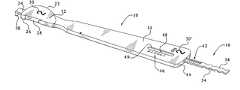
- FIG. 1is a perspective view of one side of one preferred embodiment of the tibial sizer of the present invention, shown with the slider inserted into the channel;
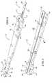
- FIG. 2is a perspective view of the tibial sizer of FIG. 1 , shown from the opposite side and without the slider;
- FIG. 3is a cross-sectional view of the tibial sizer of FIG. 1 , taken along line III—III of FIG. 2 , showing the channel for receiving the slider;
- FIG. 4is a perspective view of the slider, without the remainder of the tibial sizer
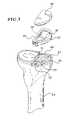
- FIG. 5is a view of a resected tibia, shown with an example of a tibial base plate of a unicompartmental knee prosthesis.
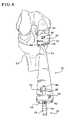
- FIG. 6is a view of the tibial sizer of FIG. 1 positioned upon the cut surface of a resected tibia.
- the sizerincludes a head 12 and a handle 14 , as well as a separate slider 16 that is configured to slide within the head and handle.
- the outer periphery of the headis shaped to correspond to the outer periphery of a tibial base plate, one example of which is shown in FIG. 5 and is designated as base plate 18 .
- tibial base plate 18is configured for use with a plastic insert 20 .
- the present inventionmay also be used with other types of tibial base plates, such as those of unitary construction whereby the insert is not a separate component.
- the tibial base plate 18is intended to be implanted into the resected portion 21 of a tibia 24 .
- the tibial sizer 10is capable of being used on both the left and the right tibia, and on either the medial compartment or the lateral compartment of either tibia. However, for the sake of convenience in description, the tibial sizer will primarily be shown and described with respect to the medial compartment of the right tibia, and the terms lateral, medial, etc. relative to the right tibia will be used. Of course, if the prosthesis was being implanted into the left tibia, the surfaces on the prosthesis and the tibial sizer designated as lateral and medial would be reversed.
- FIG. 1shows the tibial sizer 10 as it would be positioned for use in the medial compartment of the right tibia
- FIG. 6shows the tibial sizer in such a position.
- Head 12includes a curved outer peripheral surface 22 connected to a generally flat posterior outer peripheral surface 24 , which is itself connected to another generally flat outer peripheral surface 26 .
- the curved outer peripheral surface 22is the medial outer peripheral surface of head 12
- surface 26is the lateral outer peripheral surface of the head.
- the generally flat lateral outer peripheral surface 26includes a cutout portion 28 , which can be used as a guide to create a cut, or to mark the position of a cut, to accommodate a keel on a tibial implant (such as keel 29 shown in FIG. 5 ), as described more fully below.
- a cutout portion 28can be used as a guide to create a cut, or to mark the position of a cut, to accommodate a keel on a tibial implant (such as keel 29 shown in FIG. 5 ), as described more fully below.
- the outer peripheral surfaces 22 , 24 , and 26 of the tibial sizerare shaped and sized like the corresponding outer peripheral surfaces of the tibial base plate 18 of FIG. 5 . More specifically, curved outer peripheral surface 22 of the sizer 10 ( FIG. 1 ) corresponds to curved outer peripheral surface 22 ′ of base plate 18 ( FIG. 5 ) and generally flat outer peripheral surface 26 of the sizer 10 ( FIG. 1 ) corresponds to generally flat outer peripheral surface 26 ′ of base plate 18 ( FIG. 5 ). Additionally, generally flat posterior outer peripheral surface 24 of the sizer 10 corresponds to the generally flat posterior outer peripheral surface of the base plate 18 (which surface is hidden from view in FIG. 5 ).
- tibial sizersIn order to accommodate the range of sizes of tibial base plates, there should be a set of tibial sizers with heads 12 of a variety of different sizes, with one head corresponding in size to each size of tibial base plate 18 . For example, if there are six different sizes of tibial base plate 18 , there should be six different sizes of tibial sizer 10 . In order to readily show the size of a particular tibial sizer, size markings such as markings 30 and 30 ′ should be provided on at least one location, and preferably at two locations, as shown in FIG. 1 . Further, the size markings 30 / 30 ′ should coincide with the size markings on the tibial base plates.
- tibial sizers 10should also be designated as “Size 1”, “Size 2”, etc.
- each sizercan be used for any one of the four compartments (i.e., lateral compartment of the right tibia, medial compartment of the right tibia, lateral compartment of the left tibia, and medial compartment of the left tibia). More specifically, the orientation shown in FIG. 1 is used for the medial compartment of the right tibia and for the lateral compartment of the left tibia; and the orientation shown in FIG. 2 (which is merely the slider of FIG. 1 turned upside down) is used for lateral compartment of the right tibia and for the medial compartment of the left tibia.
- tibial sizer 10In use, to determine the proper size tibial base plate to be implanted, different sized sizers 10 are placed on the resected portion 21 ( FIG. 5 ) of the tibia 24 , as shown in FIG. 6 .
- the tibial sizer 10should be placed with the flat outer peripheral surface 26 (which in this case is the lateral surface, since FIG. 5 shows the right tibia 24 ) against the surface 32 created by the sagittal cut.
- the tibial sizer 10 of the size that best covers the resected proximal tibia, without any overhang,should be selected. Care should be taken to ensure that the selected tibial sizer rests on cortical bone around its entire perimeter, without any overhang of the head 12 , in order to ensure that the tibial base plate has strong cortical support.
- the present tibial sizer 10also includes a feature for measuring the amount of exposed bone posterior to the sizer, as well as including markings for providing a suggested size of tibial base plate with regard to the anterior/posterior direction.
- This anterior/posterior size suggestion provided by the markings described belowshould be used in conjunction with the anterior/posterior size estimate provided by matching the size of the head 12 (in the anterior/posterior direction) with the size of the resected portion 21 of the tibia, as described above.
- the size estimate in the medial/lateral directionis provided by matching the size of the head 12 (in the medial/lateral direction) with the size of the resected portion 21 of the tibia, as described above.
- the amount of exposed bone posterior to the sizeris indicated by the slider 16 , which is shown inserted into the sizer 10 in FIG. 1 , and is shown removed from the sizer in FIG. 4 .
- the slider 16is configured to slide within a channel 34 ( FIG. 2 ) that extends along the longitudinal direction of 11 both the head 12 and the handle 14 .
- FIG. 3shows a cross-sectional view of the handle 14 taken along lines III—III of FIG. 2 . This cross-sectional view clearly shows the channel 34 , which also includes upper lips 36 for maintaining the slider 16 within the channel 34 .
- the channel 34is preferably configured to allow for the slider 16 to be easily removed, such as by simply pulling the slider out of the channel via a hook portion 38 .
- the present inventionrelates to a set of different sized tibial sizers 10 , with one sizer sized to correspond to each available size of tibial base plate 18 .
- one slider 16may be provided for each tibial sizer 10 .
- only one slider 16could be provided for all of the different sized tibial sizers.
- the slider (or sliders) and the sizersare all made of stainless steel, although other materials are also contemplated as being within the scope of the invention.
- the hook portion 38 of the slider 16is configured to make contact with a posterior proximal portion 40 of the tibia 24 (see FIG. 5 ).
- two different sets of markingsmay be used—one set for indicating the amount of exposed bone posterior to the sizer; and another set for providing a suggested size of tibial base plate, with respect to the anterior/posterior direction. As shown in FIGS.
- the first set of markingsindicate the amount of exposed bone between the posterior proximal portion 40 of the tibia 24 and the posterior outer peripheral surface 24 of the tibial sizer 10 .
- markings 42are located on the slider 16 , and provide the indication of exposed bone when viewed with respect to edge 44 of the handle 14 of the sizer 10 .
- markings 42are provided in millimeters, between 0 mm and 20 mm, in 2 mm increments. Of course, any desired units may be used, and other increments between units are also contemplated. Markings 42 , as well as the other types of markings described herein may be produced upon the sizer by a variety of different methods, such as laser etching, engraving, printing, etc.
- the second set of markingsprovide a suggested size of tibial base plate, with respect to the anterior/posterior direction.
- Markings 46include indicia on the handle 14 representing different sizes of tibial base plates and a pointer 48 on the slider 16 for pointing to indicate a suggested size of tibial base plate, with respect to the anterior/posterior direction and with the amount of exposed bone indicated by the first set of markings 42 .
- the pointer 48is visible through a window 49 that is provided in the handle 14 .
- the tibial sizer 10is used in the orientation shown in FIG.
- a windowis unnecessary because channel 34 is open on this side of the sizer.
- there are six different sizes of tibial base plates(numbered from 1 to 6). However, a different amount and/or a different type of indicia may be provided if the number of tibial base plates is different from six and/or if the different sizes of tibial base plates are represented by a different designation system, such as alphabetically.
- the second set of markings 46operates as follows.
- the head 12 of the appropriately sized tibial sizer 10is positioned on the resected portion 21 of the tibia, with the flat outer peripheral surface 26 against the surface 32 created by the sagittal cut ( FIGS. 5 and 6 ).
- the head 12should be aligned so that its outer peripheral surfaces 22 and 24 do not extend beyond the bone, but instead rest on cortical bone, as mentioned above. If the outer peripheral surfaces 22 or 24 do extend beyond the bone, a smaller sizer should be selected. On the other hand, if the head 12 is so small that outer peripheral surfaces 22 and/or 24 are too small to rest on cortical bone, a larger sizer should be selected.
- the slider 16After aligning the head 12 of the properly sized sizer 10 , the slider 16 is slid within the channel 34 until the hook portion 38 makes contact with the posterior proximal portion 40 ( FIG. 5 ) of the tibia 24 .
- the slider 16may optionally include a series of indentations 54 on the lateral and medial edges. With the hook portion 38 contacting posterior proximal portion 40 , the pointer 48 on the slider 16 will point to indicia 46 on the handle 14 to suggest a size of tibial base plate, with respect to the anterior/posterior direction and with the amount of exposed bone indicated by the first set of markings 42 .
- the sizer 10should be moved in the appropriate direction (i.e., the anterior direction or the posterior direction), and a different size of tibial base plate may be suggested (depending upon how much the amount of exposed bone is changed).
- the information provided by the second set of markings 46(which provides size information for the anterior/posterior direction only) should be used in conjunction with the visual indication of the suggested size of tibial base plate from the head 12 being positioned on the resected portion 21 of the tibia (which provides size information for both the anterior/posterior direction and the media/lateral direction) to select a tibial base plate of an appropriate size.
- the slidermay also include a third set of markings representing different sizes of tibial base plates indicating a suggested size of tibial base plate (with respect to the anterior/posterior direction), where the third set of markings are only usable if the slider 16 is used by itself, such as shown in FIG. 4 .
- the third set of markings, designated as markings 50 in FIG. 4includes the same indicia as the second set of markings 46 (except without the pointer 48 ).
- the third set of markings 50may be the numbers 1 through 6, which correspond to different sizes of tibial base plates.
- indicia other than the numbers 1 through 6may also be used for the third set of markings.
- the third set of markings 50which are visible when the slider 16 is used alone, operate as follows.
- the slider 16( FIG. 4 ) is positioned upon the resected portion 21 ( FIG. 5 ) of the tibia, with its hook portion 38 contacting the posterior proximal portion 40 of the tibia 24 .
- the size of tibial base plate indicated by the one of the markings 50 closest to the anterior proximal portion 52 ( FIG. 5 ) of the tibia 24is the suggested size of tibial base plate, with respect to the anterior/posterior direction.
- Using the slider alonedoes not provide information for a suggested size of tibial base plate with respect to the medial/lateral direction, nor does it provide information regarding the amount of exposed bone between a posterior proximal portion of the tibia and a posterior edge of the head the tibial sizer (and/or the tibial base plate).
- tibial sizers of the present inventionare also configured to be used on the lateral compartment of the right tibia (by orienting the sizer 10 as shown in FIG. 2 ), as well as on the lateral compartment of the left tibia ( FIG. 1 orientation) and the medial compartment of the left tibia ( FIG. 2 orientation).
- TKAtotal knee arthroplasty
- the surgeonviews the resected portion 21 and roughly estimates the appropriate size of tibial base plate needed, and selects (from a set of tibial sizers of different sizes) a tibial sizer 10 of a size that corresponds to a tibial base plate of the estimated size.
- the surgeonplaces the head 12 of the selected tibial sizer 10 on the cut surface 21 of the resected tibia so that the generally flat outer peripheral surface 26 (i.e., the lateral surface) of the head 12 of the tibial sizer 10 is against a surface 32 created by a sagittal cut.
- the surgeonverifies that the outer medial periphery 22 of the head 12 sufficiently covers the resected tibia, without extending beyond cortical bone 23 ( FIG. 5 ). If the outer medial periphery 22 of the head 12 does not provide appropriate coverage, the surgeon selects another tibial sizer 10 of a different size, and performs the verifying step again with the newly selected tibial sizer. If necessary, additional sizers are selected until the appropriate size has been found.
- the slider 16is inserted into the channel 34 .
- the slidermay be inserted into the channel earlier, if desired.
- the slideris slid until the hook 38 found on a slider 16 contacts a posterior edge 40 of the tibia 24 .
- the surgeonviews a first set of markings 42 that indicate the amount of exposed bone between the posterior proximal portion 40 of the tibia 24 and the posterior edge 24 of the head 12 of the tibial sizer 10 . If the amount of bone exposed is too high or too low, the surgeon may choose to select a different size tibial base plate than the size that corresponds to the tibial sizer being used. If a size change is needed, the steps described may be repeated with a sizer that corresponds to the newly chosen size.
- a suggested size of tibial base plateis provided by the surgeon's viewing of a second set of markings 46 .
- the surgeonconsiders the position of the pointer 48 along indicia 46 , which indicates suggested different sizes of tibial base plates for the amount of exposed bone indicated by the first set of markings 42 .
- the surgeondetermines the appropriate size of tibial base plate to use. Then, the tibial base plate of the selected size is implanted using any desired method, and the arthroplasty continues as known to those of ordinary skill in the art.
- the surgeonmay also opt to use the cutout portion 28 on the head 12 of the tibial sizer 10 as a guide for either marking a desired location of a cut to accept a keel (such as keel 29 of FIG. 5 ) of the tibial implant or for directly creating a cut to accept the keel 29 . More specifically, the head 12 of the sizer is positioned on the resected portion 21 ( FIG. 5 ) of the tibia, and it is properly aligned, as shown in FIG. 6 .
- the surgeonmerely uses the cutout portion 28 as a guide to mark the bone, using known marking methods, and the bone is then cut or punched using known methods, where it was marked, in order to provide a space 31 for the keel 29 of the tibial implant.
- the surgeonwants to directly cut the space 31 for the keel 29 , he/she may use the cutout portion 28 directly for guiding the saw blade used to make the space for the keel.
Landscapes
- Health & Medical Sciences (AREA)
- Surgery (AREA)
- Life Sciences & Earth Sciences (AREA)
- Heart & Thoracic Surgery (AREA)
- Pathology (AREA)
- Oral & Maxillofacial Surgery (AREA)
- Engineering & Computer Science (AREA)
- Biomedical Technology (AREA)
- Nuclear Medicine, Radiotherapy & Molecular Imaging (AREA)
- Medical Informatics (AREA)
- Molecular Biology (AREA)
- Animal Behavior & Ethology (AREA)
- General Health & Medical Sciences (AREA)
- Public Health (AREA)
- Veterinary Medicine (AREA)
- Prostheses (AREA)
Abstract
Description
Claims (10)
Priority Applications (1)
| Application Number | Priority Date | Filing Date | Title |
|---|---|---|---|
| US10/792,337US7172599B2 (en) | 2004-03-03 | 2004-03-03 | Tibial sizer |
Applications Claiming Priority (1)
| Application Number | Priority Date | Filing Date | Title |
|---|---|---|---|
| US10/792,337US7172599B2 (en) | 2004-03-03 | 2004-03-03 | Tibial sizer |
Publications (2)
| Publication Number | Publication Date |
|---|---|
| US20050203541A1 US20050203541A1 (en) | 2005-09-15 |
| US7172599B2true US7172599B2 (en) | 2007-02-06 |
Family
ID=34919740
Family Applications (1)
| Application Number | Title | Priority Date | Filing Date |
|---|---|---|---|
| US10/792,337Expired - LifetimeUS7172599B2 (en) | 2004-03-03 | 2004-03-03 | Tibial sizer |
Country Status (1)
| Country | Link |
|---|---|
| US (1) | US7172599B2 (en) |
Cited By (37)
| Publication number | Priority date | Publication date | Assignee | Title |
|---|---|---|---|---|
| US20040138670A1 (en)* | 2003-01-15 | 2004-07-15 | Robert Metzger | Method and apparatus for less invasive knee resection |
| US20050113840A1 (en)* | 2003-01-15 | 2005-05-26 | Robert Metzger | Method and apparatus for less invasive knee resection |
| US20050149042A1 (en)* | 2003-01-15 | 2005-07-07 | Robert Metzger | Instrumentation for knee resection |
| US20060020284A1 (en)* | 2004-07-26 | 2006-01-26 | Foley Kevin T | Systems and methods for determining optimal retractor length in minimally invasive procedures |
| US20060142774A1 (en)* | 2003-01-15 | 2006-06-29 | Biomet Manufacturing Corp. | Instrumentation for knee resection |
| US20070233140A1 (en)* | 2006-02-27 | 2007-10-04 | Biomet Manufacturing Corp. | Femoral adjustment device and associated method |
| US20090149859A1 (en)* | 2003-12-08 | 2009-06-11 | Biomet Manufacturing Corp. | Femoral Guide For Implanting A Femoral Knee Prosthesis |
| US20090275950A1 (en)* | 2007-05-02 | 2009-11-05 | Arthrex, Inc. | Flip retrograde cutting instrument |
| US7695479B1 (en)* | 2005-04-12 | 2010-04-13 | Biomet Manufacturing Corp. | Femoral sizer |
| US20110004260A1 (en)* | 2009-07-02 | 2011-01-06 | Gary Scott Sherman | Arthroscopic tibial sizer |
| US8070752B2 (en) | 2006-02-27 | 2011-12-06 | Biomet Manufacturing Corp. | Patient specific alignment guide and inter-operative adjustment |
| US8265949B2 (en) | 2007-09-27 | 2012-09-11 | Depuy Products, Inc. | Customized patient surgical plan |
| US8343159B2 (en) | 2007-09-30 | 2013-01-01 | Depuy Products, Inc. | Orthopaedic bone saw and method of use thereof |
| US8357111B2 (en) | 2007-09-30 | 2013-01-22 | Depuy Products, Inc. | Method and system for designing patient-specific orthopaedic surgical instruments |
| US20140296861A1 (en)* | 2013-03-29 | 2014-10-02 | Gary Robert McCarthy | Tunnel gage |
| US8979847B2 (en) | 2011-06-06 | 2015-03-17 | Biomet Manufacturing, Llc | Method and apparatus for implanting a knee prosthesis |
| US20150216611A1 (en)* | 2014-01-31 | 2015-08-06 | Biomet Manufacturing, Llc | Orthopaedic implant template and method of making |
| US9402566B2 (en) | 2012-08-31 | 2016-08-02 | Tenzin Llc | Orthopedic measurement devices, systems and methods |
| US9700329B2 (en) | 2006-02-27 | 2017-07-11 | Biomet Manufacturing, Llc | Patient-specific orthopedic instruments |
| US9743935B2 (en) | 2011-03-07 | 2017-08-29 | Biomet Manufacturing, Llc | Patient-specific femoral version guide |
| US9795399B2 (en) | 2006-06-09 | 2017-10-24 | Biomet Manufacturing, Llc | Patient-specific knee alignment guide and associated method |
| US9839464B2 (en) | 2010-03-18 | 2017-12-12 | Smith & Nephew, Inc. | Device and method for use during ligament reconstruction |
| US20170360577A1 (en)* | 2016-06-17 | 2017-12-21 | Paragon 28, Inc. | Implants, devices, systems, kits and methods of implanting |
| US9913734B2 (en) | 2006-02-27 | 2018-03-13 | Biomet Manufacturing, Llc | Patient-specific acetabular alignment guides |
| US9968376B2 (en) | 2010-11-29 | 2018-05-15 | Biomet Manufacturing, Llc | Patient-specific orthopedic instruments |
| US10159498B2 (en) | 2008-04-16 | 2018-12-25 | Biomet Manufacturing, Llc | Method and apparatus for manufacturing an implant |
| US10206695B2 (en) | 2006-02-27 | 2019-02-19 | Biomet Manufacturing, Llc | Femoral acetabular impingement guide |
| US10278711B2 (en) | 2006-02-27 | 2019-05-07 | Biomet Manufacturing, Llc | Patient-specific femoral guide |
| US10390845B2 (en) | 2006-02-27 | 2019-08-27 | Biomet Manufacturing, Llc | Patient-specific shoulder guide |
| US10426492B2 (en) | 2006-02-27 | 2019-10-01 | Biomet Manufacturing, Llc | Patient specific alignment guide with cutting surface and laser indicator |
| US10507029B2 (en) | 2006-02-27 | 2019-12-17 | Biomet Manufacturing, Llc | Patient-specific acetabular guides and associated instruments |
| US10603179B2 (en) | 2006-02-27 | 2020-03-31 | Biomet Manufacturing, Llc | Patient-specific augments |
| US10722310B2 (en) | 2017-03-13 | 2020-07-28 | Zimmer Biomet CMF and Thoracic, LLC | Virtual surgery planning system and method |
| US10743937B2 (en) | 2006-02-27 | 2020-08-18 | Biomet Manufacturing, Llc | Backup surgical instrument system and method |
| US11051829B2 (en) | 2018-06-26 | 2021-07-06 | DePuy Synthes Products, Inc. | Customized patient-specific orthopaedic surgical instrument |
| US11534313B2 (en) | 2006-02-27 | 2022-12-27 | Biomet Manufacturing, Llc | Patient-specific pre-operative planning |
| US11554019B2 (en) | 2007-04-17 | 2023-01-17 | Biomet Manufacturing, Llc | Method and apparatus for manufacturing an implant |
Families Citing this family (14)
| Publication number | Priority date | Publication date | Assignee | Title |
|---|---|---|---|---|
| US7094241B2 (en) | 2002-11-27 | 2006-08-22 | Zimmer Technology, Inc. | Method and apparatus for achieving correct limb alignment in unicondylar knee arthroplasty |
| US7641661B2 (en) | 2003-12-26 | 2010-01-05 | Zimmer Technology, Inc. | Adjustable resection guide |
| US8167888B2 (en) | 2004-08-06 | 2012-05-01 | Zimmer Technology, Inc. | Tibial spacer blocks and femoral cutting guide |
| US20060095048A1 (en)* | 2004-10-29 | 2006-05-04 | Zannis Anthony D | Method of repairing soft tissue using sizing templates |
| US7780671B2 (en) | 2006-01-23 | 2010-08-24 | Zimmer Technology, Inc. | Bone resection apparatus and method for knee surgery |
| US20090018544A1 (en)* | 2007-07-13 | 2009-01-15 | Zimmer, Inc. | Method and apparatus for soft tissue balancing |
| US8845641B2 (en)* | 2008-10-31 | 2014-09-30 | Zimmer, Inc. | Expandable arthroplasty plates |
| US20140058446A1 (en)* | 2011-09-28 | 2014-02-27 | Avi Bernstein | Spinal implant system |
| US8523875B2 (en)* | 2011-10-11 | 2013-09-03 | Smith & Nephew, Inc. | Graft caliper marking device |
| US9386998B2 (en) | 2011-10-27 | 2016-07-12 | Smith & Nephew, Inc. | Devices and methods for performing knee arthroplasty |
| US8672948B2 (en)* | 2011-10-27 | 2014-03-18 | Warsaw Orthopedic, Inc. | Vertebral spacer size indicator |
| US9462967B2 (en)* | 2012-07-06 | 2016-10-11 | Zimmer, Inc. | Condyle axis locator |
| US10524934B2 (en)* | 2016-12-30 | 2020-01-07 | Zimmer, Inc. | Shoulder arthroplasty trial device |
| GB201919043D0 (en)* | 2019-12-20 | 2020-02-05 | Depuy Ireland Ultd Co | Adjustable tibial sizer |
Citations (12)
| Publication number | Priority date | Publication date | Assignee | Title |
|---|---|---|---|---|
| US1011628A (en)* | 1911-02-25 | 1911-12-12 | Jacob Klein | Tape-measure. |
| US1431873A (en)* | 1921-02-24 | 1922-10-10 | Clausing George | Foot tape for measuring shoes |
| US1962518A (en)* | 1928-11-24 | 1934-06-12 | Pro Ker Lab Inc | Means for ascertaining the hair production of a subject |
| US1981911A (en)* | 1933-11-16 | 1934-11-27 | Engelsman Monroe | Ring and finger gauge |
| US2531477A (en)* | 1949-09-26 | 1950-11-28 | Smith Aesculapius Maurice | Foot measuring device |
| US3197875A (en)* | 1962-01-19 | 1965-08-03 | Daroff & Sons Inc H | Sleeve measuring device |
| US3300864A (en)* | 1964-05-11 | 1967-01-31 | Dallam O Brien Jr A | Eyebrow measuring and marking guide |
| US4211228A (en)* | 1979-01-24 | 1980-07-08 | Cloutier Jean Marie | Multipurpose tibial template |
| US4759350A (en)* | 1986-10-17 | 1988-07-26 | Dunn Harold K | Instruments for shaping distal femoral and proximal tibial surfaces |
| US6063091A (en)* | 1998-10-13 | 2000-05-16 | Stryker Technologies Corporation | Methods and tools for tibial intermedullary revision surgery and associated tibial components |
| US20040122441A1 (en)* | 2002-12-09 | 2004-06-24 | Zimmer Kabushiki Kaisha | Measuring apparatus for total knee replacement operation |
| US6979299B2 (en)* | 2002-02-05 | 2005-12-27 | Zimmer Austin, Inc. | Measuring guide for use in orthopedic procedure |
- 2004
- 2004-03-03USUS10/792,337patent/US7172599B2/ennot_activeExpired - Lifetime
Patent Citations (12)
| Publication number | Priority date | Publication date | Assignee | Title |
|---|---|---|---|---|
| US1011628A (en)* | 1911-02-25 | 1911-12-12 | Jacob Klein | Tape-measure. |
| US1431873A (en)* | 1921-02-24 | 1922-10-10 | Clausing George | Foot tape for measuring shoes |
| US1962518A (en)* | 1928-11-24 | 1934-06-12 | Pro Ker Lab Inc | Means for ascertaining the hair production of a subject |
| US1981911A (en)* | 1933-11-16 | 1934-11-27 | Engelsman Monroe | Ring and finger gauge |
| US2531477A (en)* | 1949-09-26 | 1950-11-28 | Smith Aesculapius Maurice | Foot measuring device |
| US3197875A (en)* | 1962-01-19 | 1965-08-03 | Daroff & Sons Inc H | Sleeve measuring device |
| US3300864A (en)* | 1964-05-11 | 1967-01-31 | Dallam O Brien Jr A | Eyebrow measuring and marking guide |
| US4211228A (en)* | 1979-01-24 | 1980-07-08 | Cloutier Jean Marie | Multipurpose tibial template |
| US4759350A (en)* | 1986-10-17 | 1988-07-26 | Dunn Harold K | Instruments for shaping distal femoral and proximal tibial surfaces |
| US6063091A (en)* | 1998-10-13 | 2000-05-16 | Stryker Technologies Corporation | Methods and tools for tibial intermedullary revision surgery and associated tibial components |
| US6979299B2 (en)* | 2002-02-05 | 2005-12-27 | Zimmer Austin, Inc. | Measuring guide for use in orthopedic procedure |
| US20040122441A1 (en)* | 2002-12-09 | 2004-06-24 | Zimmer Kabushiki Kaisha | Measuring apparatus for total knee replacement operation |
Non-Patent Citations (1)
| Title |
|---|
| Intramedullary Surgical Approach-The M/G(TM) Unicompartmental Knee Minimally Invasive Surgical Technique; by Zimmer, Inc., 2002; pp. 1-24 (with special emphasis directed to p. 18). |
Cited By (80)
| Publication number | Priority date | Publication date | Assignee | Title |
|---|---|---|---|---|
| US9023053B2 (en) | 2003-01-15 | 2015-05-05 | Biomet Manufacturing, Llc | Instrumentation for knee resection |
| US20050113840A1 (en)* | 2003-01-15 | 2005-05-26 | Robert Metzger | Method and apparatus for less invasive knee resection |
| US20050149042A1 (en)* | 2003-01-15 | 2005-07-07 | Robert Metzger | Instrumentation for knee resection |
| US8551100B2 (en) | 2003-01-15 | 2013-10-08 | Biomet Manufacturing, Llc | Instrumentation for knee resection |
| US20060142774A1 (en)* | 2003-01-15 | 2006-06-29 | Biomet Manufacturing Corp. | Instrumentation for knee resection |
| US20040138670A1 (en)* | 2003-01-15 | 2004-07-15 | Robert Metzger | Method and apparatus for less invasive knee resection |
| US20110130762A1 (en)* | 2003-01-15 | 2011-06-02 | Biomet Manufacturing Corp. | Method for Less Invasive Knee Resection |
| US7887542B2 (en) | 2003-01-15 | 2011-02-15 | Biomet Manufacturing Corp. | Method and apparatus for less invasive knee resection |
| US8870883B2 (en) | 2003-01-15 | 2014-10-28 | Biomet Manufacturing, Llc | Method for less invasive knee resection |
| US9693788B2 (en) | 2003-01-15 | 2017-07-04 | Biomet Manufacturing, Llc | Instrumentation for knee resection |
| US7837690B2 (en) | 2003-01-15 | 2010-11-23 | Biomet Manufacturing Corp. | Method and apparatus for less invasive knee resection |
| US7789885B2 (en) | 2003-01-15 | 2010-09-07 | Biomet Manufacturing Corp. | Instrumentation for knee resection |
| US8518047B2 (en) | 2003-01-15 | 2013-08-27 | Biomet Manufacturing, Llc | Method and apparatus for less invasive knee resection |
| US20100318089A1 (en)* | 2003-01-15 | 2010-12-16 | Robert Metzger | Method and apparatus for less invasive knee resection |
| US20090149859A1 (en)* | 2003-12-08 | 2009-06-11 | Biomet Manufacturing Corp. | Femoral Guide For Implanting A Femoral Knee Prosthesis |
| US8834486B2 (en) | 2003-12-08 | 2014-09-16 | Biomet Manufacturing, Llc | Femoral guide for implanting a femoral knee prosthesis |
| US8123758B2 (en) | 2003-12-08 | 2012-02-28 | Biomet Manufacturing Corp. | Femoral guide for implanting a femoral knee prosthesis |
| US7434325B2 (en)* | 2004-07-26 | 2008-10-14 | Warsaw Orthopedic, Inc. | Systems and methods for determining optimal retractor length in minimally invasive procedures |
| US20060020284A1 (en)* | 2004-07-26 | 2006-01-26 | Foley Kevin T | Systems and methods for determining optimal retractor length in minimally invasive procedures |
| US7695479B1 (en)* | 2005-04-12 | 2010-04-13 | Biomet Manufacturing Corp. | Femoral sizer |
| US10603179B2 (en) | 2006-02-27 | 2020-03-31 | Biomet Manufacturing, Llc | Patient-specific augments |
| US10426492B2 (en) | 2006-02-27 | 2019-10-01 | Biomet Manufacturing, Llc | Patient specific alignment guide with cutting surface and laser indicator |
| US9913734B2 (en) | 2006-02-27 | 2018-03-13 | Biomet Manufacturing, Llc | Patient-specific acetabular alignment guides |
| US9700329B2 (en) | 2006-02-27 | 2017-07-11 | Biomet Manufacturing, Llc | Patient-specific orthopedic instruments |
| US10206695B2 (en) | 2006-02-27 | 2019-02-19 | Biomet Manufacturing, Llc | Femoral acetabular impingement guide |
| US11534313B2 (en) | 2006-02-27 | 2022-12-27 | Biomet Manufacturing, Llc | Patient-specific pre-operative planning |
| US10278711B2 (en) | 2006-02-27 | 2019-05-07 | Biomet Manufacturing, Llc | Patient-specific femoral guide |
| US10743937B2 (en) | 2006-02-27 | 2020-08-18 | Biomet Manufacturing, Llc | Backup surgical instrument system and method |
| US10390845B2 (en) | 2006-02-27 | 2019-08-27 | Biomet Manufacturing, Llc | Patient-specific shoulder guide |
| US7780672B2 (en) | 2006-02-27 | 2010-08-24 | Biomet Manufacturing Corp. | Femoral adjustment device and associated method |
| US8070752B2 (en) | 2006-02-27 | 2011-12-06 | Biomet Manufacturing Corp. | Patient specific alignment guide and inter-operative adjustment |
| US20070233140A1 (en)* | 2006-02-27 | 2007-10-04 | Biomet Manufacturing Corp. | Femoral adjustment device and associated method |
| US10507029B2 (en) | 2006-02-27 | 2019-12-17 | Biomet Manufacturing, Llc | Patient-specific acetabular guides and associated instruments |
| US10893879B2 (en) | 2006-06-09 | 2021-01-19 | Biomet Manufacturing, Llc | Patient-specific knee alignment guide and associated method |
| US9795399B2 (en) | 2006-06-09 | 2017-10-24 | Biomet Manufacturing, Llc | Patient-specific knee alignment guide and associated method |
| US10206697B2 (en) | 2006-06-09 | 2019-02-19 | Biomet Manufacturing, Llc | Patient-specific knee alignment guide and associated method |
| US11576689B2 (en) | 2006-06-09 | 2023-02-14 | Biomet Manufacturing, Llc | Patient-specific knee alignment guide and associated method |
| US11554019B2 (en) | 2007-04-17 | 2023-01-17 | Biomet Manufacturing, Llc | Method and apparatus for manufacturing an implant |
| US8652139B2 (en)* | 2007-05-02 | 2014-02-18 | Arthrex, Inc. | Flip retrograde cutting instrument |
| US9101366B2 (en) | 2007-05-02 | 2015-08-11 | Arthrex, Inc. | Flip retrograde cutting instrument |
| US20090275950A1 (en)* | 2007-05-02 | 2009-11-05 | Arthrex, Inc. | Flip retrograde cutting instrument |
| US8265949B2 (en) | 2007-09-27 | 2012-09-11 | Depuy Products, Inc. | Customized patient surgical plan |
| US12070231B2 (en) | 2007-09-27 | 2024-08-27 | DePuy Synthes Products, Inc. | Customized patient surgical plan |
| US10028750B2 (en) | 2007-09-30 | 2018-07-24 | DePuy Synthes Products, Inc. | Apparatus and method for fabricating a customized patient-specific orthopaedic instrument |
| US11696768B2 (en) | 2007-09-30 | 2023-07-11 | DePuy Synthes Products, Inc. | Apparatus and method for fabricating a customized patient-specific orthopaedic instrument |
| US8398645B2 (en) | 2007-09-30 | 2013-03-19 | DePuy Synthes Products, LLC | Femoral tibial customized patient-specific orthopaedic surgical instrumentation |
| US8343159B2 (en) | 2007-09-30 | 2013-01-01 | Depuy Products, Inc. | Orthopaedic bone saw and method of use thereof |
| US10828046B2 (en) | 2007-09-30 | 2020-11-10 | DePuy Synthes Products, Inc. | Apparatus and method for fabricating a customized patient-specific orthopaedic instrument |
| US8377068B2 (en) | 2007-09-30 | 2013-02-19 | DePuy Synthes Products, LLC. | Customized patient-specific instrumentation for use in orthopaedic surgical procedures |
| US8361076B2 (en) | 2007-09-30 | 2013-01-29 | Depuy Products, Inc. | Patient-customizable device and system for performing an orthopaedic surgical procedure |
| US8357166B2 (en) | 2007-09-30 | 2013-01-22 | Depuy Products, Inc. | Customized patient-specific instrumentation and method for performing a bone re-cut |
| US8357111B2 (en) | 2007-09-30 | 2013-01-22 | Depuy Products, Inc. | Method and system for designing patient-specific orthopaedic surgical instruments |
| US11931049B2 (en) | 2007-09-30 | 2024-03-19 | DePuy Synthes Products, Inc. | Apparatus and method for fabricating a customized patient-specific orthopaedic instrument |
| US10159498B2 (en) | 2008-04-16 | 2018-12-25 | Biomet Manufacturing, Llc | Method and apparatus for manufacturing an implant |
| US8535330B2 (en)* | 2009-07-02 | 2013-09-17 | Arthrex, Inc. | Arthroscopic tibial sizer |
| US20110004260A1 (en)* | 2009-07-02 | 2011-01-06 | Gary Scott Sherman | Arthroscopic tibial sizer |
| US11324522B2 (en) | 2009-10-01 | 2022-05-10 | Biomet Manufacturing, Llc | Patient specific alignment guide with cutting surface and laser indicator |
| US10893876B2 (en) | 2010-03-05 | 2021-01-19 | Biomet Manufacturing, Llc | Method and apparatus for manufacturing an implant |
| US9839464B2 (en) | 2010-03-18 | 2017-12-12 | Smith & Nephew, Inc. | Device and method for use during ligament reconstruction |
| US9883899B2 (en) | 2010-03-18 | 2018-02-06 | Smith & Nephew, Inc. | Device and method for use during ligament reconstruction |
| US11234719B2 (en) | 2010-11-03 | 2022-02-01 | Biomet Manufacturing, Llc | Patient-specific shoulder guide |
| US9968376B2 (en) | 2010-11-29 | 2018-05-15 | Biomet Manufacturing, Llc | Patient-specific orthopedic instruments |
| US9743935B2 (en) | 2011-03-07 | 2017-08-29 | Biomet Manufacturing, Llc | Patient-specific femoral version guide |
| US10744005B2 (en) | 2011-06-06 | 2020-08-18 | Biomet Manufacturing, Llc | Method and apparatus for implanting a knee prosthesis |
| US9770345B2 (en) | 2011-06-06 | 2017-09-26 | Biomet Manufacturing, Llc | Method and apparatus for implanting a knee prosthesis |
| US12357477B2 (en) | 2011-06-06 | 2025-07-15 | Biomet Manufacturing, Llc | Method and apparatus for implanting a knee prosthesis |
| US11660212B2 (en) | 2011-06-06 | 2023-05-30 | Biomet Manufacturing, Llc | Method and apparatus for implanting a knee prosthesis |
| US8979847B2 (en) | 2011-06-06 | 2015-03-17 | Biomet Manufacturing, Llc | Method and apparatus for implanting a knee prosthesis |
| US10595750B2 (en) | 2012-08-31 | 2020-03-24 | Tenzin Llc | Orthopedic measurement devices, systems and methods |
| US9402566B2 (en) | 2012-08-31 | 2016-08-02 | Tenzin Llc | Orthopedic measurement devices, systems and methods |
| US20160324591A1 (en)* | 2013-03-29 | 2016-11-10 | Smith & Nephew, Inc. | Tunnel gage |
| US20140296861A1 (en)* | 2013-03-29 | 2014-10-02 | Gary Robert McCarthy | Tunnel gage |
| US9386997B2 (en)* | 2013-03-29 | 2016-07-12 | Smith & Nephew, Inc. | Tunnel gage |
| US10149733B2 (en)* | 2013-03-29 | 2018-12-11 | Smith & Nephew, Inc. | Tunnel gage |
| US20150216611A1 (en)* | 2014-01-31 | 2015-08-06 | Biomet Manufacturing, Llc | Orthopaedic implant template and method of making |
| US10470900B2 (en)* | 2016-06-17 | 2019-11-12 | Paragon 28, Inc. | Implants, devices, systems, kits and methods of implanting |
| US20170360577A1 (en)* | 2016-06-17 | 2017-12-21 | Paragon 28, Inc. | Implants, devices, systems, kits and methods of implanting |
| US10722310B2 (en) | 2017-03-13 | 2020-07-28 | Zimmer Biomet CMF and Thoracic, LLC | Virtual surgery planning system and method |
| US11051829B2 (en) | 2018-06-26 | 2021-07-06 | DePuy Synthes Products, Inc. | Customized patient-specific orthopaedic surgical instrument |
| US11950786B2 (en) | 2018-06-26 | 2024-04-09 | DePuy Synthes Products, Inc. | Customized patient-specific orthopaedic surgical instrument |
Also Published As
| Publication number | Publication date |
|---|---|
| US20050203541A1 (en) | 2005-09-15 |
Similar Documents
| Publication | Publication Date | Title |
|---|---|---|
| US7172599B2 (en) | Tibial sizer | |
| EP1263331B1 (en) | Apparatus for use in arthroplasty on a knee joint | |
| US20180353190A1 (en) | Methods and apparatus for performing knee arthroplasty | |
| US4566466A (en) | Surgical instrument | |
| US20170143324A1 (en) | Spacer block | |
| CN110638508B (en) | Customized, patient-specific plastic surgery devices | |
| US20060155294A1 (en) | Tibial/femoral recutter with paddle | |
| EP0720834A2 (en) | Instrumentation for use in orthopaedic surgery | |
| AU2001240345A1 (en) | Apparatus for use in arthroplasty of the knees | |
| US7115133B2 (en) | Simple-to-use size measurer | |
| WO1998046192A3 (en) | Radial pocket forming and insert positioning instruments, corneal marker, and method for using same | |
| US7727238B2 (en) | Determination device for size of cutting block using connection device | |
| US20090062806A1 (en) | Tibial preparation apparatus and method | |
| CN108024819B (en) | Guide for positioning cutting block | |
| US8915923B2 (en) | Patella resection assembly | |
| CN110337281A (en) | Knee prosthesis implant system and method involving relative tibial rotation | |
| AU2021278309A1 (en) | Unicondylar cutting block | |
| US11723554B2 (en) | Adjustable tibial sizer | |
| AU2001240341B2 (en) | A method of arthroplasty on a knee joint and apparatus for use in same | |
| AU2005203714B2 (en) | A method of arthroplasty on a knee joint and apparatus for use in same | |
| WO2017108774A1 (en) | Femoral sizing apparatus | |
| AU2005201571A1 (en) | Apparatus for use in arthroplasty of the knees |
Legal Events
| Date | Code | Title | Description |
|---|---|---|---|
| AS | Assignment | Owner name:ZIMMER TECHNOLOGY, INC., ILLINOIS Free format text:ASSIGNMENT OF ASSIGNORS INTEREST;ASSIGNORS:STEFFENSMEIER, SCOTT;MICHAEL, JEFFREY;REEL/FRAME:015437/0036;SIGNING DATES FROM 20040301 TO 20040408 | |
| STCF | Information on status: patent grant | Free format text:PATENTED CASE | |
| FEPP | Fee payment procedure | Free format text:PAYER NUMBER DE-ASSIGNED (ORIGINAL EVENT CODE: RMPN); ENTITY STATUS OF PATENT OWNER: LARGE ENTITY Free format text:PAYOR NUMBER ASSIGNED (ORIGINAL EVENT CODE: ASPN); ENTITY STATUS OF PATENT OWNER: LARGE ENTITY | |
| FPAY | Fee payment | Year of fee payment:4 | |
| FPAY | Fee payment | Year of fee payment:8 | |
| AS | Assignment | Owner name:ZIMMER, INC., INDIANA Free format text:MERGER;ASSIGNOR:ZIMMER TECHNOLOGY, INC.;REEL/FRAME:035107/0073 Effective date:20121127 | |
| AS | Assignment | Owner name:SMITH & NEPHEW, INC., TENNESSEE Free format text:ASSIGNMENT OF ASSIGNORS INTEREST;ASSIGNORS:ZIMMER BIOMET HOLDINGS, INC.;ZIMMER, INC.;REEL/FRAME:036054/0585 Effective date:20150629 | |
| MAFP | Maintenance fee payment | Free format text:PAYMENT OF MAINTENANCE FEE, 12TH YEAR, LARGE ENTITY (ORIGINAL EVENT CODE: M1553) Year of fee payment:12 |