US7172012B1 - Investment casting - Google Patents
Investment castingDownload PDFInfo
- Publication number
- US7172012B1 US7172012B1US10/891,660US89166004AUS7172012B1US 7172012 B1US7172012 B1US 7172012B1US 89166004 AUS89166004 AUS 89166004AUS 7172012 B1US7172012 B1US 7172012B1
- Authority
- US
- United States
- Prior art keywords
- core
- feed
- installing
- spine
- investment casting
- Prior art date
- Legal status (The legal status is an assumption and is not a legal conclusion. Google has not performed a legal analysis and makes no representation as to the accuracy of the status listed.)
- Expired - Lifetime
Links
Images


Classifications
- B—PERFORMING OPERATIONS; TRANSPORTING
- B22—CASTING; POWDER METALLURGY
- B22C—FOUNDRY MOULDING
- B22C7/00—Patterns; Manufacture thereof so far as not provided for in other classes
- B22C7/02—Lost patterns
- B—PERFORMING OPERATIONS; TRANSPORTING
- B22—CASTING; POWDER METALLURGY
- B22C—FOUNDRY MOULDING
- B22C9/00—Moulds or cores; Moulding processes
- B22C9/02—Sand moulds or like moulds for shaped castings
- B22C9/04—Use of lost patterns
- B—PERFORMING OPERATIONS; TRANSPORTING
- B22—CASTING; POWDER METALLURGY
- B22C—FOUNDRY MOULDING
- B22C9/00—Moulds or cores; Moulding processes
- B22C9/10—Cores; Manufacture or installation of cores
- B22C9/103—Multipart cores
- B—PERFORMING OPERATIONS; TRANSPORTING
- B22—CASTING; POWDER METALLURGY
- B22D—CASTING OF METALS; CASTING OF OTHER SUBSTANCES BY THE SAME PROCESSES OR DEVICES
- B22D29/00—Removing castings from moulds, not restricted to casting processes covered by a single main group; Removing cores; Handling ingots
Definitions
- the inventionrelates to investment casting. More particularly, the invention relates to the forming of core-containing patterns for investment forming investment casting molds.
- Investment castingis a commonly used technique for forming metallic components having complex geometries, especially hollow components, and is used in the fabrication of superalloy gas turbine engine components.
- Gas turbine enginesare widely used in aircraft propulsion, electric power generation, ship propulsion, and pumps. In gas turbine engine applications, efficiency is a prime objective. Improved gas turbine engine efficiency can be obtained by operating at higher temperatures, however current operating temperatures in the turbine section exceed the melting points of the superalloy materials used in turbine components. Consequently, it is a general practice to provide air cooling. Cooling is typically provided by flowing relatively cool air from the compressor section of the engine through passages in the turbine components to be cooled. Such cooling comes with an associated cost in engine efficiency. Consequently, there is a strong desire to provide enhanced specific cooling, maximizing the amount of cooling benefit obtained from a given amount of cooling air. This may be obtained by the use of fine, precisely located, cooling passageway sections.
- a moldis prepared having one or more mold cavities, each having a shape generally corresponding to the part to be cast.
- An exemplary process for preparing the moldinvolves the use of one or more wax patterns of the part. The patterns are formed by molding wax over ceramic cores generally corresponding to positives of the cooling passages within the parts.
- a ceramic shellis formed around one or more such patterns in a well known fashion. The wax may be removed such as by melting, e.g., in an autoclave. The shell may be fired to harden the shell.
- a moldcomprising the shell having one or more part-defining compartments which, in turn, contain the ceramic core(s) defining the cooling passages.
- Molten alloymay then be introduced to the mold to cast the part(s).
- the shell and coremay be mechanically and/or chemically removed from the molded part(s).
- the part(s)can then be machined and/or treated in one or more stages.
- the ceramic coresthemselves may be formed by molding a mixture of ceramic powder and binder material by injecting the mixture into hardened metal dies. After removal from the dies, the green cores may then be thermally post-processed to remove the binder and fired to sinter the ceramic powder together.
- the trend toward finer cooling featureshas taxed ceramic core manufacturing techniques.
- the cores defining fine featuresmay be difficult to manufacture and/or, once manufactured, may prove fragile.
- EDMelectro-discharge machining
- the refractory metal coresmay become damaged during handling or during assembly of the overmolding die. Assuring proper die assembly and release of the injected pattern may require die complexity (e.g., a large number of separate die parts and separate pull directions to accommodate the various RMCs).
- One aspect of the inventioninvolves a method for forming an investment casting pattern.
- a first coreis installed to a first element of a molding die to leave a first portion of the first core protruding from the first element.
- the first elementis assembled with a feed core and a second element of the molding die so that the first portion contacts the feed core and is flexed.
- a materialis molded at least partially over the first core and feed core.
- the assemblingmay include causing engagement between the first core and feed core to at least partially maintain an orientation of the feed core relative to the molding die.
- a second coremay be installed to the second element to leave a first portion of the second core protruding from the second element.
- a second coremay be installed to the first element to leave a first portion of the second core protruding from the first element.
- the first coremay have a spine and a number of tines extending from the spine.
- the first coremay comprise, in major weight part, one or more refractory metals.
- the feed coremay comprise, in major weight part, one or more ceramic materials and/or refractory metals.
- the materialmay comprise, in major weight part, one or more waxes.
- An investment casting patternmay be formed as described above.
- One or more coating layersmay be applied to the pattern.
- the materialmay be substantially removed to leave the first core and feed core within a shell formed by the coating layers.
- the methodmay be used to fabricate a gas turbine engine airfoil element mold.
- Another aspect of the inventioninvolves a method for investment casting.
- An investment casting moldis formed as described above. Molten metal is introduced to the investment casting mold. The molten metal is permitted to solidify. The investment casting mold is destructively removed. The method may be used to fabricate a gas turbine engine component.
- the componentincludes a spine and a number of tines extending from the spine.
- the spine and tinesmay be unitarily formed and may consist essentially of a refractory metal-based material, optionally coated.
- the tinesmay be tapered over a first region from a relatively wide cross-section proximal root at least to a relatively small cross-section intermediate location.
- the tinesmay be less tapered over a second region, distally of the first region.
- the spinemay have integrally-formed spring elements. There may be at least six such tines.
- the spinemay provide at least 90% of a mass of the component.
- the tinesmay be at least five mm in length.
- the spinemay define a direction of insertion for inserting the spine into a die. The tines may extend off-parallel to the direction of insertion.
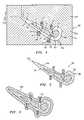
- FIG. 1is a view of a refractory metal core (RMC).
- RMCrefractory metal core
- FIG. 2is a front view of the RMC of FIG. 1 .
- FIG. 3is an end view of the RMC of FIG. 1 .
- FIG. 4is a sectional view of a die for wax molding a core assembly.
- FIG. 5is a sectional view of an airfoil of a pattern molded in the die of FIG. 4 .
- FIG. 6is a sectional view of a shelled pattern from the precursor of FIG. 5 .
- FIG. 7is a sectional view of cast metal in a shell formed from the shelled pattern of FIG. 6 .
- FIG. 8is a sectional view of a part formed by the cast metal of FIG. 7 .
- FIG. 9is a view of an alternate RMC.
- FIG. 1shows an exemplary refractory metal core (RMC) 20 which may include a refractory metal substrate and, optionally, a coating (e.g., ceramic).
- RMC substrate materialsinclude Mo, Nb, Ta, and W alone or in combination and in elemental form, alloy, intermetallic, and the like.
- the RMC 20may be formed by any of a variety of manufacturing techniques, for example, those used to form EDM comb electrodes.
- the substratemay be formed by milling from a refractory metal ingot or stamping and bending a refractory metal sheet, or by build up using multiple sheets. The substrate may then be coated (e.g., with a full ceramic coating or a coating limited to areas that will ultimately contact molten metal).
- the exemplary RMC 20is intended to be illustrative of one possible general configuration. Other configurations, including simpler and more complex configurations are possible.
- a core precursorcould be manufactured having a spine and tines and individual cores separated from the precursor, with the individual cores each having one or more of the tines. Individual cores with one to a few tines could be useful, for example, where only isolated holes or small groups thereof are desired or where it is desired that the holes be of varying shape/size, staggered out of line, of varying spacing, and the like.
- the exemplary RMC 20may be comb-like, having a back or spine 22 and a row of teeth or tines 24 extending therefrom. other forms are possible.
- a spine 22extends between first and second ends 26 and 28 ( FIG. 2 ) and has inboard and outboard surfaces 30 and 32 .
- the teeth 24extend from the inboard surface 30 .
- An exemplary number of teethis 4–20, more narrowly, 6–12.
- the exemplary spineis formed as a portion of a generally right parallelepiped and thus has two additional surfaces or faces 34 and 36 .
- the face 34is a forward face and the face 36 is an aft face (with fore and aft corresponding to generally upstream and downstream positions in an exemplary airfoil to be cast using the RMC 20 ).
- the exemplary teeth 24each extend from a proximal root 38 at the inboard surface 30 to a distal tip 40 .
- the exemplary teetheach have a proximal portion 42 and a distal portion 44 meeting at an intermediate junction 46 .
- the exemplary distal portion 44is of relatively constant cross-sectional area and shape (e.g., circular or rounded square shape) and extends along a median axis 500 with a length L 1 .
- the proximal portion 42is of generally proximally divergent cross-sectional area and has a median axis 502 and a characteristic length L 2 .
- the proximal portionmay be of generally relatively non-constant cross-sectional shape (e.g., transitioning from the shape of the distal portion to an aftward/downstream divergent shape such as a triangle with a rounded leading corner). Nevertheless, the distal portion could have a non-constant shape and the proximal portion could have a constant shape. Alternatively the entire tine could have constant cross-section.
- a tooth-to-tooth pitch L 3is defined as the tip separation of adjacent teeth.
- the pitchmay be constant or varied as may be the length and cross-sectional shape and dimensions of the teeth. For example, these parameters may be varied to provide a desired cooling distribution.
- the array of teethhas an overall length L 4 .
- the spinehas an overall length L 5 , a thickness T, and a principal height H. These parameters may be chosen to permit a desired tooth/hole distribution in view of economy factors (e.g., it may be more economical in labor savings to have one RMC with many teeth rather than a number of RMCs each with a lesser number of teeth).
- the exemplary spinehas a pair of arcuate spring tabs 50 extending above a principal portion of the outboard surface 32 (e.g., cut and bent from a remaining portion of the spine).
- the distal portions 44may extend at an angle ⁇ 1 ( FIG. 3 ) relative to a direction 504 which may be orthogonal to the outboard surface 32 when viewed from the side and an angle ⁇ 2 ( FIG. 2 ) when viewed from the front.
- the distal and proximal portionsmay be at angles ⁇ 3 and ⁇ 4 from each other when viewed from these directions. ⁇ 1 – ⁇ 4 need not be the same for each tooth.
- FIG. 4shows a number of such RMCs 20 positioned with their spines 22 in compartments 56 of a pattern-forming die 58 having first and second halves 60 and 62 .
- the compartmentsmay be shaped and dimensioned to precisely orient and position the associated spines.
- the exemplary die halvesare formed of metal or of a composite (e.g., epoxy-based).
- the die halvesare shown assembled, meeting along a parting junction 508 .
- the die halvesmay have passageways 64 for the introduction of wax to a void 66 and may be joined and separated along a pull direction 510 which may correspond with the direction 504 of each of the RMCs.
- FIG. 4further shows a ceramic feed core 70 having portions 72 , 73 , and 74 (e.g., joined by webs 75 ) for forming three spanwise feed passageways in an airfoil of the part (e.g., a turbine blade or vane) to be cast.
- Alternative feed coresmay be made of other materials such as refractory metals or ceramic/refractory combinations or assemblies.
- the dieincludes surfaces 76 and 78 for forming suction and pressure side surfaces of the pattern airfoil.
- the inboard surfaces 30are advantageously shaped and angled to generally correspond to their associated surface 76 or 78 .
- portions of the spinescould protrude beyond an otherwise continuous curve of the associated surface (e.g., to ultimately form the cast part with a shallow slot connecting outlets of through-holes formed by the tines.
- the tips 40contact the feed core and help position the feed core.
- the RMCsmay be placed in the associated die halves and the feed core then lowered into place and engagement with the RMCs of the lower half (e.g., 62 ). Thereafter, the upper half may be joined via translation along the pull direction 510 , bringing its associated RMCs into engagement with the feed core.
- Other RMCs of other formsmay also be installed during the mold assembly process or may be preinstalled to the feed core.
- the tipsmay be slightly resiliently flexed during the mold assembly process to help position the feed core either during wax molding or later (as described below).
- the flexionmay be maintained by cooperation of the spring tabs 50 with base portions 80 of the compartments 56 so as to bias the tips 40 into contact with the feed core.
- the feed core 70may have recesses for receiving the tips 40 which may improve tip positioning relative to the feed core.
- FIG. 5shows the pattern 90 after the molding of wax 92 and the removal of the pattern from the die 58 .
- the patternhas an exterior surface characterized by suction and pressure side surfaces 94 and 96 extending between a leading edge 98 and a trailing edge 100 .
- the strain/flexing of the RMCs during the wax molding processis sufficiently low so that the wax is sufficiently strong to maintain the relative positioning and engagement of the RMCs and feed core 70 .
- the patternmay be assembled to a shelling fixture (e.g., via wax welding between upper and lower end plates of the fixture) and a multilayer ceramic slurry/stucco coating 120 ( FIG. 6 ) applied for forming a shell.
- the RMC body portions 22become embedded in the shell 120 .
- a dewax processe.g., in a steam autoclave
- This core and shell assemblymay be fired to harden the shell.
- Molten casting material 130(FIG.
- the RMCs 70may then be introduced to the shell to fill the spaces between the core assembly and the shell.
- the RMCs 70may continue to help maintain the desired position/orientation of the feed core 70 .
- the shell 120may be destructively removed (e.g., broken away via an impact apparatus and/or chemical immersion process) and the RMCs and feed core destructively removed (e.g., via a chemical immersion apparatus) from the cast metal to form a part precursor (e.g., a rough or unfinished part) 140 ( FIG. 8 ). Thereafter, the precursor may be subject to machining, treatment (e.g., thermal, mechanical, or chemical), and coating (e.g., metallic environmental coating/bond coat and/or ceramic heat resistant coating) to form the final component.
- machining, treatmente.g., thermal, mechanical, or chemical
- coatinge.g., metallic environmental coating/bond coat and/or ceramic heat resistant coating
- FIG. 8further shows the discharge cooling passageways formed by the RMC teeth.
- the passagewayseach have a small cross-section upstream metering portion 150 formed by the teeth distal portions and a downstream diffusing portion 152 formed by the teeth proximal portions.
- Such portionsmay have shape and dimensions as are known in the art or may yet be developed.
- passageways with arcuate (e.g., non-constant radius of curvature) longitudinal sections, passageways with twist or with at least local downstream-wise decrease in cross-section, or otherwise convoluted passagewaysmay be formed which might be impossible to form via drilling or EDM.
- Exemplary overall tine lengthsare 0.5–13 mm, more narrowly 3.0–7.0 mm, depending essentially upon the wall thickness of the part and the overall tine angle relative to the part outer surface.
- exemplary tine distal portion axes(and thus passageway metering portions) are 15–90° off the part outer surface, more narrowly 20–40°.
- Exemplary cross-sectional areas of the metering portionsare 0.03–0.8 mm 2 .
- Exemplary maximum transverse dimensions of the metering portionsare 0.2–1.0 mm.
- FIG. 9shows an alternate RMC 200 which may be stamped and bent from sheet stock.
- the RMC 200has a generally flat main body portion 202 extending from an upstream end 204 to a downstream end 206 and having first and second lateral ends 208 and 210 .
- the main body portionhas a number of projections 212 for forming inlets to a serpentine passageway system in the cast part formed by ultimate removal of the main body portion 202 .
- Each projection 212is continuous with a feed core-engagement portion 214 extending at an angle off-parallel to the main body portion and which may be received in a complementary pocket in the feed core.
- a spine 220is formed adjacent the downstream end 206 .
- Apertures 222interrupt a proximal portion of the spine 220 and a downstream portion of the body 202 .
- the aperturesultimately form intact casting portions between outlet slots in a similar fashion to outlet slots disclosed in U.S. Pat. No. 6,705,831.
- the spine 220may be positioned within a complementary compartment of the pattern-forming die and brought into flexed engagement with the associated feed core(s) during die assembly.
- the foregoing teachingsmay be implemented in the manufacturing of pre-existing patterns (core combinations and wax shapes) or to produce novel patterns not yet designed.
Landscapes
- Engineering & Computer Science (AREA)
- Mechanical Engineering (AREA)
- Molds, Cores, And Manufacturing Methods Thereof (AREA)
- Turbine Rotor Nozzle Sealing (AREA)
- Braking Arrangements (AREA)
Abstract
Description
Claims (19)
Priority Applications (6)
| Application Number | Priority Date | Filing Date | Title |
|---|---|---|---|
| US10/891,660US7172012B1 (en) | 2004-07-14 | 2004-07-14 | Investment casting |
| KR1020050057416AKR100686658B1 (en) | 2004-07-14 | 2005-06-30 | Investment Casting |
| JP2005201148AJP2006026742A (en) | 2004-07-14 | 2005-07-11 | Method for forming pattern for investment casting, investment casting method and its constitution parts |
| EP05254403AEP1616642B1 (en) | 2004-07-14 | 2005-07-14 | Investment casting |
| AT05254403TATE524255T1 (en) | 2004-07-14 | 2005-07-14 | INVESTMENT CASTING |
| US11/333,967US7520312B2 (en) | 2004-07-14 | 2006-01-17 | Investment casting |
Applications Claiming Priority (1)
| Application Number | Priority Date | Filing Date | Title |
|---|---|---|---|
| US10/891,660US7172012B1 (en) | 2004-07-14 | 2004-07-14 | Investment casting |
Related Child Applications (1)
| Application Number | Title | Priority Date | Filing Date |
|---|---|---|---|
| US11/333,967DivisionUS7520312B2 (en) | 2004-07-14 | 2006-01-17 | Investment casting |
Publications (1)
| Publication Number | Publication Date |
|---|---|
| US7172012B1true US7172012B1 (en) | 2007-02-06 |
Family
ID=34941835
Family Applications (2)
| Application Number | Title | Priority Date | Filing Date |
|---|---|---|---|
| US10/891,660Expired - LifetimeUS7172012B1 (en) | 2004-07-14 | 2004-07-14 | Investment casting |
| US11/333,967Expired - Fee RelatedUS7520312B2 (en) | 2004-07-14 | 2006-01-17 | Investment casting |
Family Applications After (1)
| Application Number | Title | Priority Date | Filing Date |
|---|---|---|---|
| US11/333,967Expired - Fee RelatedUS7520312B2 (en) | 2004-07-14 | 2006-01-17 | Investment casting |
Country Status (5)
| Country | Link |
|---|---|
| US (2) | US7172012B1 (en) |
| EP (1) | EP1616642B1 (en) |
| JP (1) | JP2006026742A (en) |
| KR (1) | KR100686658B1 (en) |
| AT (1) | ATE524255T1 (en) |
Cited By (39)
| Publication number | Priority date | Publication date | Assignee | Title |
|---|---|---|---|---|
| US20070175009A1 (en)* | 2006-01-27 | 2007-08-02 | Snecma | Method of manufacturing a turbomachine component that includes cooling air discharge orifices |
| US20070284411A1 (en)* | 2006-05-15 | 2007-12-13 | United Technologies Corporation | Investment casting core assembly |
| US20080006384A1 (en)* | 2004-07-14 | 2008-01-10 | Memmen Robert L | Investment casting |
| US20080060781A1 (en)* | 2005-09-01 | 2008-03-13 | United Technologies Corporation | Investment Casting Pattern Manufacture |
| US20080110024A1 (en)* | 2006-11-14 | 2008-05-15 | Reilly P Brennan | Airfoil casting methods |
| US20090053041A1 (en)* | 2007-08-22 | 2009-02-26 | Pinero Hector M | Gas turbine engine case for clearance control |
| US20090112354A1 (en)* | 2007-10-30 | 2009-04-30 | Tahany Ibrahim El-Wardany | Method of determining optimal parameters for machining a workpiece |
| US20090258102A1 (en)* | 2005-06-23 | 2009-10-15 | Edward Pietraszkiewicz | Method for forming turbine blade with angled internal ribs |
| US20090308761A1 (en)* | 2008-06-13 | 2009-12-17 | Gehron Michael J | Recast removal method |
| US20100000698A1 (en)* | 2008-07-02 | 2010-01-07 | Newton Kirk C | Casting system for investment casting process |
| US20100003142A1 (en)* | 2008-07-03 | 2010-01-07 | Piggush Justin D | Airfoil with tapered radial cooling passage |
| US20100014102A1 (en)* | 2007-06-07 | 2010-01-21 | United Technologies Corporation | Cooled Wall Thickness Control |
| US20100054953A1 (en)* | 2008-08-29 | 2010-03-04 | Piggush Justin D | Airfoil with leading edge cooling passage |
| US20100098526A1 (en)* | 2008-10-16 | 2010-04-22 | Piggush Justin D | Airfoil with cooling passage providing variable heat transfer rate |
| US20100150733A1 (en)* | 2008-12-15 | 2010-06-17 | William Abdel-Messeh | Airfoil with wrapped leading edge cooling passage |
| US20100221098A1 (en)* | 2005-11-08 | 2010-09-02 | United Technologies Corporation | Peripheral Microcircuit Serpentine Cooling for Turbine Airfoils |
| US20100247322A1 (en)* | 2009-03-31 | 2010-09-30 | United Technologies Corporation | Internally supported airfoil and method for internally supporting a hollow airfoil during manufacturing |
| US20110113627A1 (en)* | 2008-07-16 | 2011-05-19 | Snecma | Method of manufacturing a blading component |
| US20120027619A1 (en)* | 2007-03-14 | 2012-02-02 | Jason Edward Albert | Cast features for a turbine engine airfoil |
| US20120186768A1 (en)* | 2009-06-26 | 2012-07-26 | Donald Sun | Methods for forming faucets and fixtures |
| US8434546B1 (en) | 2010-03-30 | 2013-05-07 | Honda Motor Co., Ltd. | Casting mold core retention device and method |
| US20140079542A1 (en)* | 2012-09-14 | 2014-03-20 | United Technologies Corporation | Casting of thin wall hollow airfoil sections |
| JP2014079766A (en)* | 2012-10-12 | 2014-05-08 | Mitsubishi Heavy Ind Ltd | Casting die-manufacturing method, and casting die |
| WO2014113184A1 (en)* | 2013-01-18 | 2014-07-24 | General Electric Company | Method of forming cast-in cooling holes in an aircraft component |
| US20150118057A1 (en)* | 2013-10-31 | 2015-04-30 | Ching-Pang Lee | Multi-wall gas turbine airfoil cast using a ceramic core formed with a fugitive insert and method of manufacturing same |
| US20160298462A1 (en)* | 2015-04-09 | 2016-10-13 | United Technologies Corporation | Cooling passages for a gas turbine engine component |
| US20160341049A1 (en)* | 2015-05-22 | 2016-11-24 | Rolls-Royce Plc | Cooling of turbine blades |
| US9845728B2 (en) | 2015-10-15 | 2017-12-19 | Rohr, Inc. | Forming a nacelle inlet for a turbine engine propulsion system |
| CN107913980A (en)* | 2016-10-11 | 2018-04-17 | 北京百慕航材高科技股份有限公司 | Bend pipe mould |
| EP3354368A1 (en)* | 2017-01-27 | 2018-08-01 | Rolls-Royce plc | A ceramic core for an investment casting process |
| US20190001522A1 (en)* | 2017-06-28 | 2019-01-03 | General Electric Company | Additively manufactured integrated casting core structure with ceramic shell |
| US10370980B2 (en)* | 2013-12-23 | 2019-08-06 | United Technologies Corporation | Lost core structural frame |
| US10400609B2 (en)* | 2012-06-21 | 2019-09-03 | United Technologies Corporation | Airfoil cooling circuits |
| US10974312B2 (en) | 2017-06-28 | 2021-04-13 | General Electric Company | Additively manufactured casting core-shell mold with integrated filter and ceramic shell |
| EP3825031A1 (en)* | 2019-11-22 | 2021-05-26 | Raytheon Technologies Corporation | Turbine blade casting with strongback core |
| US11173542B2 (en) | 2017-06-28 | 2021-11-16 | General Electric Company | Additively manufactured casting core-shell mold and ceramic shell with variable thermal properties |
| US11192172B2 (en) | 2017-06-28 | 2021-12-07 | General Electric Company | Additively manufactured interlocking casting core structure with ceramic shell |
| US11235378B2 (en) | 2017-06-28 | 2022-02-01 | General Electric Company | Additively manufactured casting core-shell hybrid mold and ceramic shell |
| US11433990B2 (en) | 2018-07-09 | 2022-09-06 | Rohr, Inc. | Active laminar flow control system with composite panel |
Families Citing this family (34)
| Publication number | Priority date | Publication date | Assignee | Title |
|---|---|---|---|---|
| US7306026B2 (en)* | 2005-09-01 | 2007-12-11 | United Technologies Corporation | Cooled turbine airfoils and methods of manufacture |
| US20080005903A1 (en)† | 2006-07-05 | 2008-01-10 | United Technologies Corporation | External datum system and film hole positioning using core locating holes |
| US7779892B2 (en)* | 2007-05-09 | 2010-08-24 | United Technologies Corporation | Investment casting cores and methods |
| CN102292465B (en) | 2009-05-20 | 2014-04-09 | 豪梅特公司 | Pt-Al-Hf/Zr Coating and Method |
| US9056795B2 (en)* | 2009-08-09 | 2015-06-16 | Rolls-Royce Corporation | Support for a fired article |
| US20110094698A1 (en)* | 2009-10-28 | 2011-04-28 | Howmet Corporation | Fugitive core tooling and method |
| US9272324B2 (en) | 2009-12-08 | 2016-03-01 | Siemens Energy, Inc. | Investment casting process for hollow components |
| US20130333855A1 (en)* | 2010-12-07 | 2013-12-19 | Gary B. Merrill | Investment casting utilizing flexible wax pattern tool for supporting a ceramic core along its length during wax injection |
| CN102802834B (en)* | 2010-12-07 | 2016-06-22 | 西门子能源有限公司 | Use the model casting of flexible wax pattern tool |
| US20140102656A1 (en)* | 2012-10-12 | 2014-04-17 | United Technologies Corporation | Casting Cores and Manufacture Methods |
| US9695696B2 (en) | 2013-07-31 | 2017-07-04 | General Electric Company | Turbine blade with sectioned pins |
| US10427213B2 (en) | 2013-07-31 | 2019-10-01 | General Electric Company | Turbine blade with sectioned pins and method of making same |
| EP3157694B1 (en)* | 2014-06-18 | 2020-07-29 | Mikro Systems Inc. | Turbine blade investment casting using film hole protrusions for integral wall thickness control |
| US10337353B2 (en)* | 2014-12-31 | 2019-07-02 | General Electric Company | Casing ring assembly with flowpath conduction cut |
| US10307816B2 (en) | 2015-10-26 | 2019-06-04 | United Technologies Corporation | Additively manufactured core for use in casting an internal cooling circuit of a gas turbine engine component |
| US10226812B2 (en) | 2015-12-21 | 2019-03-12 | United Technologies Corporation | Additively manufactured core for use in casting an internal cooling circuit of a gas turbine engine component |
| US10465527B2 (en)* | 2016-11-17 | 2019-11-05 | General Electric Company | Support for a multi-wall core |
| US20180161859A1 (en)* | 2016-12-13 | 2018-06-14 | General Electric Company | Integrated casting core-shell structure for making cast component with non-linear holes |
| US20180161857A1 (en)* | 2016-12-13 | 2018-06-14 | General Electric Company | Integrated casting core-shell structure for making cast components having thin root components |
| US20180161852A1 (en)* | 2016-12-13 | 2018-06-14 | General Electric Company | Integrated casting core-shell structure with printed tubes for making cast component |
| US20180161854A1 (en)* | 2016-12-13 | 2018-06-14 | General Electric Company | Integrated casting core-shell structure |
| US11813669B2 (en) | 2016-12-13 | 2023-11-14 | General Electric Company | Method for making an integrated core-shell structure |
| US20180161866A1 (en)* | 2016-12-13 | 2018-06-14 | General Electric Company | Multi-piece integrated core-shell structure for making cast component |
| DE102017106775A1 (en)* | 2017-03-29 | 2018-10-04 | Nemak, S.A.B. De C.V. | Casting core and process for its production |
| US20190111472A1 (en)* | 2017-10-18 | 2019-04-18 | General Electric Company | High temperature engineering stiffness core-shell mold for casting |
| US20190375000A1 (en)* | 2018-06-11 | 2019-12-12 | United Technologies Corporation | Method for casting cooling holes for an internal cooling circuit of a gas turbine engine component |
| US11642720B2 (en)* | 2019-10-16 | 2023-05-09 | Raytheon Technologies Corporation | Integral core bumpers |
| US12311574B2 (en)* | 2020-08-14 | 2025-05-27 | Rtx Corporation | Method and system for molded coating on CMC |
| US11685123B2 (en) | 2020-12-01 | 2023-06-27 | Raytheon Technologies Corporation | Erodible support structure for additively manufactured article and process therefor |
| US12168309B2 (en) | 2021-05-11 | 2024-12-17 | General Electric Company | Methods for casting a component via a unitary core-shell mold |
| US12410753B2 (en) | 2022-11-01 | 2025-09-09 | General Electric Company | Gas turbine engine |
| US12428992B2 (en) | 2022-11-01 | 2025-09-30 | General Electric Company | Gas turbine engine |
| US12392290B2 (en) | 2022-11-01 | 2025-08-19 | General Electric Company | Gas turbine engine |
| US12196131B2 (en) | 2022-11-01 | 2025-01-14 | General Electric Company | Gas turbine engine |
Citations (20)
| Publication number | Priority date | Publication date | Assignee | Title |
|---|---|---|---|---|
| US3596703A (en)* | 1968-10-01 | 1971-08-03 | Trw Inc | Method of preventing core shift in casting articles |
| US3604884A (en) | 1969-04-24 | 1971-09-14 | Essar Corp | Electrode feed control for edm machine |
| US3957104A (en) | 1974-02-27 | 1976-05-18 | The United States Of America As Represented By The Administrator Of The United States National Aeronautics And Space Administration | Method of making an apertured casting |
| US4197443A (en) | 1977-09-19 | 1980-04-08 | General Electric Company | Method and apparatus for forming diffused cooling holes in an airfoil |
| GB2111881A (en)* | 1981-12-16 | 1983-07-13 | Vickers Plc | Investment casting process and mould |
| GB2150875A (en) | 1983-12-07 | 1985-07-10 | Rolls Royce | Investment casting |
| US4819325A (en) | 1987-06-01 | 1989-04-11 | Technical Manufacturing Systems, Inc. | Method of forming electro-discharge machining electrode |
| US4922076A (en) | 1987-06-01 | 1990-05-01 | Technical Manufacturing Systems, Inc. | Electro-discharge machining electrode |
| US5382133A (en) | 1993-10-15 | 1995-01-17 | United Technologies Corporation | High coverage shaped diffuser film hole for thin walls |
| US5605639A (en) | 1993-12-21 | 1997-02-25 | United Technologies Corporation | Method of producing diffusion holes in turbine components by a multiple piece electrode |
| US5637239A (en) | 1995-03-31 | 1997-06-10 | United Technologies Corporation | Curved electrode and method for electrical discharge machining curved cooling holes |
| US5735335A (en) | 1995-07-11 | 1998-04-07 | Extrude Hone Corporation | Investment casting molds and cores |
| US6003756A (en) | 1997-10-21 | 1999-12-21 | Allison Advanced Development Company | Airfoil for gas a turbine engine and method of manufacture |
| US6530416B1 (en) | 1998-05-14 | 2003-03-11 | Siemens Aktiengesellschaft | Method and device for producing a metallic hollow body |
| US6595748B2 (en)* | 2001-08-02 | 2003-07-22 | General Electric Company | Trichannel airfoil leading edge cooling |
| US6637500B2 (en) | 2001-10-24 | 2003-10-28 | United Technologies Corporation | Cores for use in precision investment casting |
| US6668906B2 (en) | 2002-04-29 | 2003-12-30 | United Technologies Corporation | Shaped core for cast cooling passages and enhanced part definition |
| US6705831B2 (en) | 2002-06-19 | 2004-03-16 | United Technologies Corporation | Linked, manufacturable, non-plugging microcircuits |
| US6773230B2 (en)* | 2001-06-14 | 2004-08-10 | Rolls-Royce Plc | Air cooled aerofoil |
| US20050087319A1 (en)* | 2003-10-16 | 2005-04-28 | Beals James T. | Refractory metal core wall thickness control |
Family Cites Families (5)
| Publication number | Priority date | Publication date | Assignee | Title |
|---|---|---|---|---|
| US5296308A (en)* | 1992-08-10 | 1994-03-22 | Howmet Corporation | Investment casting using core with integral wall thickness control means |
| WO1999002431A1 (en)* | 1997-07-11 | 1999-01-21 | Kecskes Gyoergy | Trash container, waste collecting vehicle, and indoor trash bin for collecting waste materials selectively |
| US6556411B1 (en)* | 2002-04-02 | 2003-04-29 | Marconi Communications, Inc. | Purge protection cartridge with three-way attachment clip |
| US7124546B2 (en)* | 2003-11-18 | 2006-10-24 | Pella Corporation | Muntin bar connector with positioning tabs |
| US7172012B1 (en)* | 2004-07-14 | 2007-02-06 | United Technologies Corporation | Investment casting |
- 2004
- 2004-07-14USUS10/891,660patent/US7172012B1/ennot_activeExpired - Lifetime
- 2005
- 2005-06-30KRKR1020050057416Apatent/KR100686658B1/ennot_activeExpired - Fee Related
- 2005-07-11JPJP2005201148Apatent/JP2006026742A/enactivePending
- 2005-07-14EPEP05254403Apatent/EP1616642B1/ennot_activeExpired - Lifetime
- 2005-07-14ATAT05254403Tpatent/ATE524255T1/ennot_activeIP Right Cessation
- 2006
- 2006-01-17USUS11/333,967patent/US7520312B2/ennot_activeExpired - Fee Related
Patent Citations (21)
| Publication number | Priority date | Publication date | Assignee | Title |
|---|---|---|---|---|
| US3596703A (en)* | 1968-10-01 | 1971-08-03 | Trw Inc | Method of preventing core shift in casting articles |
| US3604884A (en) | 1969-04-24 | 1971-09-14 | Essar Corp | Electrode feed control for edm machine |
| US3957104A (en) | 1974-02-27 | 1976-05-18 | The United States Of America As Represented By The Administrator Of The United States National Aeronautics And Space Administration | Method of making an apertured casting |
| US4197443A (en) | 1977-09-19 | 1980-04-08 | General Electric Company | Method and apparatus for forming diffused cooling holes in an airfoil |
| GB2111881A (en)* | 1981-12-16 | 1983-07-13 | Vickers Plc | Investment casting process and mould |
| GB2150875A (en) | 1983-12-07 | 1985-07-10 | Rolls Royce | Investment casting |
| US4819325A (en) | 1987-06-01 | 1989-04-11 | Technical Manufacturing Systems, Inc. | Method of forming electro-discharge machining electrode |
| US4922076A (en) | 1987-06-01 | 1990-05-01 | Technical Manufacturing Systems, Inc. | Electro-discharge machining electrode |
| US5382133A (en) | 1993-10-15 | 1995-01-17 | United Technologies Corporation | High coverage shaped diffuser film hole for thin walls |
| US5605639A (en) | 1993-12-21 | 1997-02-25 | United Technologies Corporation | Method of producing diffusion holes in turbine components by a multiple piece electrode |
| US5637239A (en) | 1995-03-31 | 1997-06-10 | United Technologies Corporation | Curved electrode and method for electrical discharge machining curved cooling holes |
| US5735335A (en) | 1995-07-11 | 1998-04-07 | Extrude Hone Corporation | Investment casting molds and cores |
| US6003756A (en) | 1997-10-21 | 1999-12-21 | Allison Advanced Development Company | Airfoil for gas a turbine engine and method of manufacture |
| US6530416B1 (en) | 1998-05-14 | 2003-03-11 | Siemens Aktiengesellschaft | Method and device for producing a metallic hollow body |
| US6773230B2 (en)* | 2001-06-14 | 2004-08-10 | Rolls-Royce Plc | Air cooled aerofoil |
| US6595748B2 (en)* | 2001-08-02 | 2003-07-22 | General Electric Company | Trichannel airfoil leading edge cooling |
| US6637500B2 (en) | 2001-10-24 | 2003-10-28 | United Technologies Corporation | Cores for use in precision investment casting |
| US20040020629A1 (en) | 2001-10-24 | 2004-02-05 | United Technologies Corporation | Cores for use in precision investment casting |
| US6668906B2 (en) | 2002-04-29 | 2003-12-30 | United Technologies Corporation | Shaped core for cast cooling passages and enhanced part definition |
| US6705831B2 (en) | 2002-06-19 | 2004-03-16 | United Technologies Corporation | Linked, manufacturable, non-plugging microcircuits |
| US20050087319A1 (en)* | 2003-10-16 | 2005-04-28 | Beals James T. | Refractory metal core wall thickness control |
Non-Patent Citations (1)
| Title |
|---|
| European Search Report for EP Patent Application No. 05254403.8. |
Cited By (71)
| Publication number | Priority date | Publication date | Assignee | Title |
|---|---|---|---|---|
| US20080006384A1 (en)* | 2004-07-14 | 2008-01-10 | Memmen Robert L | Investment casting |
| US7520312B2 (en)* | 2004-07-14 | 2009-04-21 | United Technologies Corporation | Investment casting |
| US20090258102A1 (en)* | 2005-06-23 | 2009-10-15 | Edward Pietraszkiewicz | Method for forming turbine blade with angled internal ribs |
| US7862325B2 (en)* | 2005-06-23 | 2011-01-04 | United Technologies Corporation | Apparatus for forming turbine blade with angled internal ribs |
| US20080060781A1 (en)* | 2005-09-01 | 2008-03-13 | United Technologies Corporation | Investment Casting Pattern Manufacture |
| US7438118B2 (en) | 2005-09-01 | 2008-10-21 | United Technologies Corporation | Investment casting pattern manufacture |
| US20100221098A1 (en)* | 2005-11-08 | 2010-09-02 | United Technologies Corporation | Peripheral Microcircuit Serpentine Cooling for Turbine Airfoils |
| US8215374B2 (en)* | 2005-11-08 | 2012-07-10 | United Technologies Corporation | Peripheral microcircuit serpentine cooling for turbine airfoils |
| US8220522B2 (en)* | 2005-11-08 | 2012-07-17 | United Technologies Corporation | Peripheral microcircuit serpentine cooling for turbine airfoils |
| US20070175009A1 (en)* | 2006-01-27 | 2007-08-02 | Snecma | Method of manufacturing a turbomachine component that includes cooling air discharge orifices |
| US7841083B2 (en)* | 2006-01-27 | 2010-11-30 | Snecma | Method of manufacturing a turbomachine component that includes cooling air discharge orifices |
| US7686065B2 (en)* | 2006-05-15 | 2010-03-30 | United Technologies Corporation | Investment casting core assembly |
| US20070284411A1 (en)* | 2006-05-15 | 2007-12-13 | United Technologies Corporation | Investment casting core assembly |
| US20080110024A1 (en)* | 2006-11-14 | 2008-05-15 | Reilly P Brennan | Airfoil casting methods |
| US8695683B2 (en)* | 2007-03-14 | 2014-04-15 | United Technologies Corporation | Cast features for a turbine engine airfoil |
| US20120027619A1 (en)* | 2007-03-14 | 2012-02-02 | Jason Edward Albert | Cast features for a turbine engine airfoil |
| US8955576B2 (en) | 2007-03-14 | 2015-02-17 | United Technologies Corporation | Cast features for a turbine engine airfoil |
| US20100014102A1 (en)* | 2007-06-07 | 2010-01-21 | United Technologies Corporation | Cooled Wall Thickness Control |
| US8066052B2 (en)* | 2007-06-07 | 2011-11-29 | United Technologies Corporation | Cooled wall thickness control |
| US8434997B2 (en) | 2007-08-22 | 2013-05-07 | United Technologies Corporation | Gas turbine engine case for clearance control |
| US20090053041A1 (en)* | 2007-08-22 | 2009-02-26 | Pinero Hector M | Gas turbine engine case for clearance control |
| US20090112354A1 (en)* | 2007-10-30 | 2009-04-30 | Tahany Ibrahim El-Wardany | Method of determining optimal parameters for machining a workpiece |
| US8236190B2 (en) | 2008-06-13 | 2012-08-07 | United Technologies Corporation | Recast removal method |
| US20090308761A1 (en)* | 2008-06-13 | 2009-12-17 | Gehron Michael J | Recast removal method |
| US9174271B2 (en) | 2008-07-02 | 2015-11-03 | United Technologies Corporation | Casting system for investment casting process |
| US20100000698A1 (en)* | 2008-07-02 | 2010-01-07 | Newton Kirk C | Casting system for investment casting process |
| US8157527B2 (en) | 2008-07-03 | 2012-04-17 | United Technologies Corporation | Airfoil with tapered radial cooling passage |
| US20100003142A1 (en)* | 2008-07-03 | 2010-01-07 | Piggush Justin D | Airfoil with tapered radial cooling passage |
| US20110113627A1 (en)* | 2008-07-16 | 2011-05-19 | Snecma | Method of manufacturing a blading component |
| US8615875B2 (en)* | 2008-07-16 | 2013-12-31 | Snecma | Method of manufacturing a blading component |
| US20100054953A1 (en)* | 2008-08-29 | 2010-03-04 | Piggush Justin D | Airfoil with leading edge cooling passage |
| US8572844B2 (en) | 2008-08-29 | 2013-11-05 | United Technologies Corporation | Airfoil with leading edge cooling passage |
| US20100098526A1 (en)* | 2008-10-16 | 2010-04-22 | Piggush Justin D | Airfoil with cooling passage providing variable heat transfer rate |
| US8303252B2 (en) | 2008-10-16 | 2012-11-06 | United Technologies Corporation | Airfoil with cooling passage providing variable heat transfer rate |
| US8333233B2 (en) | 2008-12-15 | 2012-12-18 | United Technologies Corporation | Airfoil with wrapped leading edge cooling passage |
| US20100150733A1 (en)* | 2008-12-15 | 2010-06-17 | William Abdel-Messeh | Airfoil with wrapped leading edge cooling passage |
| US8109725B2 (en) | 2008-12-15 | 2012-02-07 | United Technologies Corporation | Airfoil with wrapped leading edge cooling passage |
| US8240999B2 (en) | 2009-03-31 | 2012-08-14 | United Technologies Corporation | Internally supported airfoil and method for internally supporting a hollow airfoil during manufacturing |
| US20100247322A1 (en)* | 2009-03-31 | 2010-09-30 | United Technologies Corporation | Internally supported airfoil and method for internally supporting a hollow airfoil during manufacturing |
| US20120186768A1 (en)* | 2009-06-26 | 2012-07-26 | Donald Sun | Methods for forming faucets and fixtures |
| US8434546B1 (en) | 2010-03-30 | 2013-05-07 | Honda Motor Co., Ltd. | Casting mold core retention device and method |
| US10400609B2 (en)* | 2012-06-21 | 2019-09-03 | United Technologies Corporation | Airfoil cooling circuits |
| US20140079542A1 (en)* | 2012-09-14 | 2014-03-20 | United Technologies Corporation | Casting of thin wall hollow airfoil sections |
| US10024181B2 (en) | 2012-09-14 | 2018-07-17 | United Technologies Corporation | Casting of thin wall hollow airfoil sections |
| US9486853B2 (en)* | 2012-09-14 | 2016-11-08 | United Technologies Corporation | Casting of thin wall hollow airfoil sections |
| JP2014079766A (en)* | 2012-10-12 | 2014-05-08 | Mitsubishi Heavy Ind Ltd | Casting die-manufacturing method, and casting die |
| WO2014113184A1 (en)* | 2013-01-18 | 2014-07-24 | General Electric Company | Method of forming cast-in cooling holes in an aircraft component |
| US9132476B2 (en)* | 2013-10-31 | 2015-09-15 | Siemens Aktiengesellschaft | Multi-wall gas turbine airfoil cast using a ceramic core formed with a fugitive insert and method of manufacturing same |
| US20150118057A1 (en)* | 2013-10-31 | 2015-04-30 | Ching-Pang Lee | Multi-wall gas turbine airfoil cast using a ceramic core formed with a fugitive insert and method of manufacturing same |
| US10370980B2 (en)* | 2013-12-23 | 2019-08-06 | United Technologies Corporation | Lost core structural frame |
| US11085305B2 (en) | 2013-12-23 | 2021-08-10 | Raytheon Technologies Corporation | Lost core structural frame |
| US20160298462A1 (en)* | 2015-04-09 | 2016-10-13 | United Technologies Corporation | Cooling passages for a gas turbine engine component |
| US20160341049A1 (en)* | 2015-05-22 | 2016-11-24 | Rolls-Royce Plc | Cooling of turbine blades |
| US9719358B2 (en)* | 2015-05-22 | 2017-08-01 | Rolls-Royce Plc | Cooling of turbine blades |
| US9845728B2 (en) | 2015-10-15 | 2017-12-19 | Rohr, Inc. | Forming a nacelle inlet for a turbine engine propulsion system |
| CN107913980A (en)* | 2016-10-11 | 2018-04-17 | 北京百慕航材高科技股份有限公司 | Bend pipe mould |
| CN107913980B (en)* | 2016-10-11 | 2024-05-17 | 北京航空材料研究院股份有限公司 | Pipe bending die |
| EP3354368A1 (en)* | 2017-01-27 | 2018-08-01 | Rolls-Royce plc | A ceramic core for an investment casting process |
| US11235491B2 (en) | 2017-06-28 | 2022-02-01 | General Electric Company | Additively manufactured integrated casting core structure with ceramic shell |
| US10391670B2 (en)* | 2017-06-28 | 2019-08-27 | General Electric Company | Additively manufactured integrated casting core structure with ceramic shell |
| US11173542B2 (en) | 2017-06-28 | 2021-11-16 | General Electric Company | Additively manufactured casting core-shell mold and ceramic shell with variable thermal properties |
| US11192172B2 (en) | 2017-06-28 | 2021-12-07 | General Electric Company | Additively manufactured interlocking casting core structure with ceramic shell |
| US10974312B2 (en) | 2017-06-28 | 2021-04-13 | General Electric Company | Additively manufactured casting core-shell mold with integrated filter and ceramic shell |
| US11235378B2 (en) | 2017-06-28 | 2022-02-01 | General Electric Company | Additively manufactured casting core-shell hybrid mold and ceramic shell |
| US11529672B2 (en) | 2017-06-28 | 2022-12-20 | General Electric Company | Additively manufactured casting core-shell mold with integrated filter and ceramic shell |
| US20190001522A1 (en)* | 2017-06-28 | 2019-01-03 | General Electric Company | Additively manufactured integrated casting core structure with ceramic shell |
| US12162063B2 (en) | 2017-06-28 | 2024-12-10 | General Electric Company | Additively manufactured interlocking casting core structure with ceramic shell |
| US12168254B2 (en) | 2017-06-28 | 2024-12-17 | General Electric Company | Additively manufactured casting core-shell mold and ceramic shell with variable thermal properties |
| US11433990B2 (en) | 2018-07-09 | 2022-09-06 | Rohr, Inc. | Active laminar flow control system with composite panel |
| EP3825031A1 (en)* | 2019-11-22 | 2021-05-26 | Raytheon Technologies Corporation | Turbine blade casting with strongback core |
| US11203058B2 (en) | 2019-11-22 | 2021-12-21 | Raytheon Technologies Corporation | Turbine blade casting with strongback core |
Also Published As
| Publication number | Publication date |
|---|---|
| KR100686658B1 (en) | 2007-02-26 |
| ATE524255T1 (en) | 2011-09-15 |
| US20080006384A1 (en) | 2008-01-10 |
| KR20060048724A (en) | 2006-05-18 |
| EP1616642A1 (en) | 2006-01-18 |
| EP1616642B1 (en) | 2011-09-14 |
| US7520312B2 (en) | 2009-04-21 |
| JP2006026742A (en) | 2006-02-02 |
Similar Documents
| Publication | Publication Date | Title |
|---|---|---|
| US7172012B1 (en) | Investment casting | |
| EP2537606B1 (en) | Investment casting of cooled turbine airfoils | |
| US7673669B2 (en) | Investment casting cores and methods | |
| US7258156B2 (en) | Investment casting pattern manufacture | |
| EP1914030B1 (en) | Investment casting cores and their use in investment casting | |
| US7686065B2 (en) | Investment casting core assembly | |
| EP1611978B1 (en) | Investment casting | |
| EP2193859A1 (en) | Castings, casting cores, and mehtods | |
| EP1923152B1 (en) | Trubine blade casting method |
Legal Events
| Date | Code | Title | Description |
|---|---|---|---|
| AS | Assignment | Owner name:UNITED TECHNOLOGIES CORPORATION, CONNECTICUT Free format text:ASSIGNMENT OF ASSIGNORS INTEREST;ASSIGNOR:MEMMEN, ROBERT L.;REEL/FRAME:015579/0637 Effective date:20040714 | |
| STCF | Information on status: patent grant | Free format text:PATENTED CASE | |
| CC | Certificate of correction | ||
| FPAY | Fee payment | Year of fee payment:4 | |
| FPAY | Fee payment | Year of fee payment:8 | |
| MAFP | Maintenance fee payment | Free format text:PAYMENT OF MAINTENANCE FEE, 12TH YEAR, LARGE ENTITY (ORIGINAL EVENT CODE: M1553) Year of fee payment:12 | |
| AS | Assignment | Owner name:RAYTHEON TECHNOLOGIES CORPORATION, MASSACHUSETTS Free format text:CHANGE OF NAME;ASSIGNOR:UNITED TECHNOLOGIES CORPORATION;REEL/FRAME:054062/0001 Effective date:20200403 | |
| AS | Assignment | Owner name:RAYTHEON TECHNOLOGIES CORPORATION, CONNECTICUT Free format text:CORRECTIVE ASSIGNMENT TO CORRECT THE AND REMOVE PATENT APPLICATION NUMBER 11886281 AND ADD PATENT APPLICATION NUMBER 14846874. TO CORRECT THE RECEIVING PARTY ADDRESS PREVIOUSLY RECORDED AT REEL: 054062 FRAME: 0001. ASSIGNOR(S) HEREBY CONFIRMS THE CHANGE OF ADDRESS;ASSIGNOR:UNITED TECHNOLOGIES CORPORATION;REEL/FRAME:055659/0001 Effective date:20200403 | |
| AS | Assignment | Owner name:RTX CORPORATION, CONNECTICUT Free format text:CHANGE OF NAME;ASSIGNOR:RAYTHEON TECHNOLOGIES CORPORATION;REEL/FRAME:064714/0001 Effective date:20230714 |