US7171170B2 - Envelope limiting for polar modulators - Google Patents
Envelope limiting for polar modulatorsDownload PDFInfo
- Publication number
- US7171170B2 US7171170B2US10/202,501US20250102AUS7171170B2US 7171170 B2US7171170 B2US 7171170B2US 20250102 AUS20250102 AUS 20250102AUS 7171170 B2US7171170 B2US 7171170B2
- Authority
- US
- United States
- Prior art keywords
- threshold level
- modulation signal
- logic
- lower threshold
- upper threshold
- Prior art date
- Legal status (The legal status is an assumption and is not a legal conclusion. Google has not performed a legal analysis and makes no representation as to the accuracy of the status listed.)
- Expired - Lifetime, expires
Links
- 238000010586diagramMethods0.000description6
- 238000000034methodMethods0.000description6
- 230000000694effectsEffects0.000description4
- 238000001228spectrumMethods0.000description4
- 238000004891communicationMethods0.000description3
- 230000003595spectral effectEffects0.000description3
- 230000008901benefitEffects0.000description2
- 238000007493shaping processMethods0.000description2
- 238000012986modificationMethods0.000description1
- 230000004048modificationEffects0.000description1
- 230000007704transitionEffects0.000description1
Images

Classifications
- H—ELECTRICITY
- H03—ELECTRONIC CIRCUITRY
- H03G—CONTROL OF AMPLIFICATION
- H03G7/00—Volume compression or expansion in amplifiers
- H03G7/06—Volume compression or expansion in amplifiers having semiconductor devices
- H—ELECTRICITY
- H03—ELECTRONIC CIRCUITRY
- H03C—MODULATION
- H03C5/00—Amplitude modulation and angle modulation produced simultaneously or at will by the same modulating signal
- H—ELECTRICITY
- H03—ELECTRONIC CIRCUITRY
- H03F—AMPLIFIERS
- H03F1/00—Details of amplifiers with only discharge tubes, only semiconductor devices or only unspecified devices as amplifying elements
- H03F1/02—Modifications of amplifiers to raise the efficiency, e.g. gliding Class A stages, use of an auxiliary oscillation
- H—ELECTRICITY
- H03—ELECTRONIC CIRCUITRY
- H03F—AMPLIFIERS
- H03F3/00—Amplifiers with only discharge tubes or only semiconductor devices as amplifying elements
- H03F3/20—Power amplifiers, e.g. Class B amplifiers, Class C amplifiers
- H03F3/24—Power amplifiers, e.g. Class B amplifiers, Class C amplifiers of transmitter output stages
- H—ELECTRICITY
- H03—ELECTRONIC CIRCUITRY
- H03G—CONTROL OF AMPLIFICATION
- H03G3/00—Gain control in amplifiers or frequency changers
- H03G3/20—Automatic control
- H03G3/30—Automatic control in amplifiers having semiconductor devices
- H03G3/3036—Automatic control in amplifiers having semiconductor devices in high-frequency amplifiers or in frequency-changers
- H03G3/3042—Automatic control in amplifiers having semiconductor devices in high-frequency amplifiers or in frequency-changers in modulators, frequency-changers, transmitters or power amplifiers
- H—ELECTRICITY
- H04—ELECTRIC COMMUNICATION TECHNIQUE
- H04L—TRANSMISSION OF DIGITAL INFORMATION, e.g. TELEGRAPHIC COMMUNICATION
- H04L27/00—Modulated-carrier systems
- H04L27/32—Carrier systems characterised by combinations of two or more of the types covered by groups H04L27/02, H04L27/10, H04L27/18 or H04L27/26
- H04L27/34—Amplitude- and phase-modulated carrier systems, e.g. quadrature-amplitude modulated carrier systems
- H04L27/36—Modulator circuits; Transmitter circuits
- H04L27/361—Modulation using a single or unspecified number of carriers, e.g. with separate stages of phase and amplitude modulation
- H—ELECTRICITY
- H04—ELECTRIC COMMUNICATION TECHNIQUE
- H04B—TRANSMISSION
- H04B1/00—Details of transmission systems, not covered by a single one of groups H04B3/00 - H04B13/00; Details of transmission systems not characterised by the medium used for transmission
- H04B1/02—Transmitters
- H04B1/04—Circuits
- H04B2001/0408—Circuits with power amplifiers
- H04B2001/045—Circuits with power amplifiers with means for improving efficiency
Definitions
- the present inventionrelates generally to communication systems, and more particularly, to a communication transmitter using digital modulation with a time-varying envelope.
- Modem communications systemsincreasingly rely on digital modulation techniques for reliable system performance. These techniques modulate a carrier signal by varying its phase and/or amplitude.
- the heterodyne architectureis standard for radio transmitters. It uses rectangular (in-phase and quadrature-phase) data and I/Q modulation to generate the transmit signal. This architecture handles phase and amplitude modulation equally well, but also produces spurious mixing products, delivers only moderate linearity, and suffers from poor efficiency.
- a more efficient radio transmitter architectureis referred to as a polar modulator.
- This architectureeliminates several circuits, avoids mixing operations, and improves efficiency. It also introduces a new challenge, separate amplitude and phase control. The separate control is complicated by some modulation formats that null the envelope of the transmit signal. It would therefore be advantageous to reduce the amplitude modulation while still preserving the quality of the transmit signal.
- the present inventionincludes a system that intelligently compresses the amplitude modulation in polar modulators so that it can be implemented with a single-stage variable gain amplifier. Limiting the amplitude modulation range on the low side prevents collapse of the transmit signal's time-varying envelope and eases circuit implementation. Limiting the amplitude modulation range on the high side reduces the peak-to-average ratio of the waveform and thereby improves the efficiency of the radio transmitter. The limiting operation affects performance only slightly since it occurs infrequently, during the transitions between certain symbols, and at low transmits levels.
- a methodfor improving the efficiency of a radio transmitter that uses polar modulation.
- the methodcomprises the steps of interpreting radio configuration parameters that indicate a peak-to-average ratio of a transmit signal, analyzing a power control signal to determine a transmit level, re-shaping an amplitude modulation signal, and adjusting the power control signal.
- a methodfor re-shaping an amplitude modulation signal of a radio transmitter.
- the methodcomprises the steps of limiting a maximum level of the amplitude modulation signal based on a peak-to-average ratio of a transmit signal and a power control level, restricting a minimum level of the amplitude modulation signal based on the power control signal and selected distortion requirements, and controlling a single variable gain amplifier stage with the amplitude modulation signal.
- a radio transmittercomprising a control circuit for improving the efficiency of the radio transmitter's polar modulator.
- the control circuitcomprises logic to set amplitude modulation data to an upper threshold level when a modulation signal exceeds the upper threshold level, logic to set the amplitude modulation data to a lower threshold level when the modulation signal falls below the lower threshold level, and logic to transfer a portion of a power control signal to a variable gain amplifier stage based on the amplitude modulation data.
- FIG. 1 aillustrates high peak clipping envelope-limiting in accordance with the present invention
- FIG. 1 billustrates low peak floor envelope-limiting in accordance with the present invention
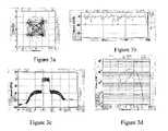
- FIGS. 2 a–dshow the effects of reducing the high peaks in an FIR-filtered QPSK-modulated signal, where (a) shows a constellation diagram, (b) shows envelope variation, (c) shows a frequency spectrum, and (d) shows an amplitude probability distribution;
- FIGS. 3 a–dshow the effects of limiting the low peaks in an FIR-filtered QPSK-modulated signal, where (a) shows a constellation diagram, (b) shows envelope variation, (c) shows a frequency spectrum, and (d) shows an amplitude probability distribution; and
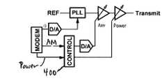
- FIG. 4shows an envelope-limiting circuit as part of the polar modulator constructed in accordance with the present invention.
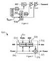
- FIG. 5shows a detailed diagram of the envelope-limiting circuit of FIG. 4 .
- the present inventionincludes a system that intelligently compresses the amplitude modulation in polar modulators so that it can be implemented with a single-stage variable gain amplifier.
- the present inventionintelligently limits the amplitude modulation signal by “clipping” its peaks and/or “softening” its nulls to allow envelope control by a single variable gain amplifier stage.
- FIGS. 1 a and 1 billustrate envelope limiting in accordance with the present invention.
- Clipping the amplitude modulation signalrestricts the maximum level of the transmit signal's envelope and introduces distortion but also improves system efficiency since this allows the transmitter to operate at lower DC power levels.
- the clippingis generally limited to a few dB or less to avoid severely affecting the transmit signal.
- FIG. 2illustrates the effects of 2 dB limiting on the FIR-filtered QPSK-modulated modulated signal.
- FIGS. 2 a–dshow (a) a constellation diagram, (b) envelope variation, (c) a frequency spectrum, and (d) an amplitude probability distribution;
- FIG. 3illustrates the effects of limiting the low peaks to 15 dB below the modulated signal's peak amplitude.
- FIGS. 3 a–dshow (a) a constellation diagram, (b) envelope variation, (c) a frequency spectrum, and (d) an amplitude probability distribution.
- FIG. 4shows an envelope-limiting circuit 400 as part of a polar modulator constructed in accordance with the present invention.
- FIG. 5shows a detailed diagram of the envelope-limiting circuit 400 of FIG. 4 .
- the circuitincludes upper adjustment logic 502 to adjust the high levels of the amplitude modulation signal (AM).
- the circuitalso includes lower adjustment logic 504 to limit the low levels of the AM signal.
- Both the logic 502 and 504comprises circuits that may be used to provide envelope limiting of the AM signal known to those with skill in the art.
- the envelope-limiting circuit 400monitors the power level of the transmit signal by comparing the power control signal 506 to a reference level (REF).
- the circuitalso interprets radio configuration parameters 510 that indicate a peak-to-average ratio of a transmit signal. This information is then used to appropriately set the lower and upper limits of a modified amplitude control signal 508
- the control circuitmoderately compresses the peaks of the amplitude modulation signal to deliver better efficiency.
- the lower limitis also set as low as possible to prevent spectral regrowth.
- the upper limitis dependant upon the peak-to-average ratio of the transmit signal (defined by the radio configuration parameters) and the linearity of the radio frequency amplifiers, while the lower limit is set by the control range of a single variable gain amplifier stage.
- the control circuitAt low transmit power levels, the control circuit only softens the nulls of the amplitude modulation signal. The peaks are unaffected. In practice, the lower limit is set to meet distortion requirements, generally much more relaxed at lower transmit power levels. This further allows a portion of the variable gain amplifier's control range to be used for power control. For example, a modified power control signal 512 is produced after the envelope limiting is accounted for via adjustment logic 514 .
- the reference levelprovides a threshold for low transmit power levels, indicating relaxed spectral regrowth requirements. Below this reference level, the lower limit of the amplitude modulation signal is either raised gradually or in a single step.
- the control circuit included in the present inventionintelligently limits the amplitude modulation signal, reshaping the transmit signal's envelope while meeting spectral regrowth requirements, allowing amplitude control by a single variable gain amplifier stage, and extending the power control range of the radio transmitter. Minor modifications and changes to the described embodiments are possible without deviating from the scope of the invention.
Landscapes
- Engineering & Computer Science (AREA)
- Power Engineering (AREA)
- Computer Networks & Wireless Communication (AREA)
- Signal Processing (AREA)
- Transmitters (AREA)
Abstract
Description
Claims (6)
Priority Applications (2)
| Application Number | Priority Date | Filing Date | Title |
|---|---|---|---|
| US10/202,501US7171170B2 (en) | 2001-07-23 | 2002-07-23 | Envelope limiting for polar modulators |
| US11/538,396US7412213B1 (en) | 2001-07-23 | 2006-10-03 | Envelope limiting for polar modulators |
Applications Claiming Priority (2)
| Application Number | Priority Date | Filing Date | Title |
|---|---|---|---|
| US30734601P | 2001-07-23 | 2001-07-23 | |
| US10/202,501US7171170B2 (en) | 2001-07-23 | 2002-07-23 | Envelope limiting for polar modulators |
Related Child Applications (1)
| Application Number | Title | Priority Date | Filing Date |
|---|---|---|---|
| US11/538,396ContinuationUS7412213B1 (en) | 2001-07-23 | 2006-10-03 | Envelope limiting for polar modulators |
Publications (2)
| Publication Number | Publication Date |
|---|---|
| US20030092405A1 US20030092405A1 (en) | 2003-05-15 |
| US7171170B2true US7171170B2 (en) | 2007-01-30 |
Family
ID=26897725
Family Applications (2)
| Application Number | Title | Priority Date | Filing Date |
|---|---|---|---|
| US10/202,501Expired - LifetimeUS7171170B2 (en) | 2001-07-23 | 2002-07-23 | Envelope limiting for polar modulators |
| US11/538,396Expired - LifetimeUS7412213B1 (en) | 2001-07-23 | 2006-10-03 | Envelope limiting for polar modulators |
Family Applications After (1)
| Application Number | Title | Priority Date | Filing Date |
|---|---|---|---|
| US11/538,396Expired - LifetimeUS7412213B1 (en) | 2001-07-23 | 2006-10-03 | Envelope limiting for polar modulators |
Country Status (1)
| Country | Link |
|---|---|
| US (2) | US7171170B2 (en) |
Cited By (19)
| Publication number | Priority date | Publication date | Assignee | Title |
|---|---|---|---|---|
| US20070205200A1 (en)* | 2006-03-02 | 2007-09-06 | Brain Box Concepts | Soap bar holder and method of supporting a soap bar |
| US20070232246A1 (en)* | 2006-03-30 | 2007-10-04 | Fujitsu Limited | Transmitter and power amplifying method |
| US7412213B1 (en)* | 2001-07-23 | 2008-08-12 | Sequoia Communications | Envelope limiting for polar modulators |
| US7479815B1 (en) | 2005-03-01 | 2009-01-20 | Sequoia Communications | PLL with dual edge sensitivity |
| US7489916B1 (en) | 2002-06-04 | 2009-02-10 | Sequoia Communications | Direct down-conversion mixer architecture |
| US7496338B1 (en) | 2003-12-29 | 2009-02-24 | Sequoia Communications | Multi-segment gain control system |
| US20090079511A1 (en)* | 2005-04-27 | 2009-03-26 | Panasonic Corporation | Polar Modulation Transmission Circuit and Communication Device |
| US7522017B1 (en) | 2004-04-21 | 2009-04-21 | Sequoia Communications | High-Q integrated RF filters |
| US7522005B1 (en) | 2006-07-28 | 2009-04-21 | Sequoia Communications | KFM frequency tracking system using an analog correlator |
| US7548122B1 (en) | 2005-03-01 | 2009-06-16 | Sequoia Communications | PLL with switched parameters |
| US7587179B1 (en) | 2001-10-04 | 2009-09-08 | Sequoia Communications | Direct synthesis transmitter |
| US7595626B1 (en) | 2005-05-05 | 2009-09-29 | Sequoia Communications | System for matched and isolated references |
| US7609118B1 (en) | 2003-12-29 | 2009-10-27 | Sequoia Communications | Phase-locked loop calibration system |
| US7672648B1 (en) | 2004-06-26 | 2010-03-02 | Quintics Holdings | System for linear amplitude modulation |
| US7675379B1 (en) | 2005-03-05 | 2010-03-09 | Quintics Holdings | Linear wideband phase modulation system |
| US7679468B1 (en) | 2006-07-28 | 2010-03-16 | Quintic Holdings | KFM frequency tracking system using a digital correlator |
| US7894545B1 (en) | 2006-08-14 | 2011-02-22 | Quintic Holdings | Time alignment of polar transmitter |
| US7920033B1 (en) | 2006-09-28 | 2011-04-05 | Groe John B | Systems and methods for frequency modulation adjustment |
| US7974374B2 (en) | 2006-05-16 | 2011-07-05 | Quintic Holdings | Multi-mode VCO for direct FM systems |
Families Citing this family (11)
| Publication number | Priority date | Publication date | Assignee | Title |
|---|---|---|---|---|
| GB2389251B (en)* | 2002-05-31 | 2005-09-07 | Hitachi Ltd | A communication semiconductor integrated circuit, a wireless communication apparatus, and a loop gain calibration method |
| US7126999B2 (en)* | 2003-08-11 | 2006-10-24 | Telefonaktiebolaget Lm Ericsson (Publ) | Pseudo-polar modulation for radio transmitters |
| US7280841B2 (en)* | 2004-12-20 | 2007-10-09 | Motorola, Inc. | System for controlling power on a mobile station and supporting method and apparatus |
| JP4829705B2 (en)* | 2006-07-12 | 2011-12-07 | 富士通株式会社 | Peak suppression control device |
| US7551026B2 (en) | 2007-07-31 | 2009-06-23 | Broadcom Corporation | Method and system for polar modulation with discontinuous phase for RF transmitters with power control |
| US8489046B2 (en)* | 2008-07-21 | 2013-07-16 | Panasonic Corporation | Signal decomposition methods and apparatus for multi-mode transmitters |
| FR2954870B1 (en)* | 2009-12-28 | 2012-08-17 | Continental Automotive France | METHOD FOR CONTROLLING THE EMISSION POWER OF A TRANSMITTER SYSTEM INCORPORATED IN AN AUTOMOTIVE VEHICLE ELECTRONIC HOUSING, AND ELECTRONIC HOUSING REALIZED |
| US8874051B2 (en)* | 2010-12-03 | 2014-10-28 | Skyworks Solutions, Inc. | Systems and methods for power control in a multiple standard mobile transmitter |
| US8855231B2 (en) | 2011-07-22 | 2014-10-07 | Qualcomm Incorporated | Methods and apparatus for signal conditioning for polar transmitters |
| CN103685117B (en)* | 2012-09-05 | 2017-05-24 | 京信通信系统(中国)有限公司 | Method and device for signal processing and signal processing cascade unit |
| CN107948116B (en)* | 2017-10-31 | 2020-02-11 | 北京理工大学 | Power amplifying device based on polar modulation |
Citations (6)
| Publication number | Priority date | Publication date | Assignee | Title |
|---|---|---|---|---|
| JPH03175823A (en)* | 1989-12-05 | 1991-07-30 | Matsushita Electric Ind Co Ltd | Transmitter amplifier |
| US5781849A (en)* | 1995-05-12 | 1998-07-14 | Telefonaktiebolaget Lm Ericsson | Spurious signal reduction in RF transmitter integrated circuits |
| US20020090921A1 (en)* | 2000-12-22 | 2002-07-11 | Jacob Midtgaard | Transmitter circuits |
| US6438360B1 (en)* | 1999-07-22 | 2002-08-20 | Motorola, Inc. | Amplifier system with load control to produce an amplitude envelope |
| US20040071225A1 (en)* | 2002-09-05 | 2004-04-15 | May Suzuki | Wireless communication apparatus |
| US6917791B2 (en)* | 2001-04-12 | 2005-07-12 | Zarlink Semiconductor Limited | Polar loop transmitter |
Family Cites Families (108)
| Publication number | Priority date | Publication date | Assignee | Title |
|---|---|---|---|---|
| US4263560A (en) | 1974-06-06 | 1981-04-21 | The United States Of America As Represented By The Secretary Of The Navy | Log-exponential AGC circuit |
| JPS6317242B1 (en) | 1978-12-05 | 1988-04-13 | Kenji Machida | |
| US4769588A (en) | 1987-09-04 | 1988-09-06 | Digital Equipment Corporation | Apparatus and method for providing a current exponentially proportional to voltage and directly proportional to temperature |
| JP2603968B2 (en) | 1987-10-12 | 1997-04-23 | 株式会社東芝 | Linear differential amplifier circuit |
| US4816772A (en) | 1988-03-09 | 1989-03-28 | Rockwell International Corporation | Wide range linear automatic gain control amplifier |
| EP0345880B1 (en) | 1988-06-08 | 1995-04-12 | Koninklijke Philips Electronics N.V. | Balanced integrator-filter arrangement |
| JPH0666614B2 (en) | 1988-11-18 | 1994-08-24 | 三洋電機株式会社 | Gain control amplifier circuit |
| US4965531A (en) | 1989-11-22 | 1990-10-23 | Carleton University | Frequency synthesizers having dividing ratio controlled by sigma-delta modulator |
| US5015968A (en) | 1990-07-27 | 1991-05-14 | Pacific Monolithics | Feedback cascode amplifier |
| GB2256550B (en) | 1991-06-04 | 1995-08-02 | Silicon Systems Inc | Differential pair based transconductance element with improved linearity and signal to noise ratio |
| US5331292A (en) | 1992-07-16 | 1994-07-19 | National Semiconductor Corporation | Autoranging phase-lock-loop circuit |
| JP3315748B2 (en) | 1993-02-19 | 2002-08-19 | 三菱電機株式会社 | Amplifier circuit |
| US5491450A (en) | 1993-06-01 | 1996-02-13 | Martin Marietta Corporation | Low power consumption process-insensitive feedback amplifier |
| EP0647032A3 (en) | 1993-10-05 | 1995-07-26 | Ibm | Charge pump circuit with symmetrical current output for phase-controlled loop system. |
| US5548594A (en) | 1993-12-28 | 1996-08-20 | Nec Corporation | Compact AGC circuit with stable characteristics |
| KR0123849B1 (en) | 1994-04-08 | 1997-11-25 | 문정환 | Internal voltage generator of semiconductor device |
| US5631587A (en) | 1994-05-03 | 1997-05-20 | Pericom Semiconductor Corporation | Frequency synthesizer with adaptive loop bandwidth |
| US5581216A (en) | 1995-01-24 | 1996-12-03 | Ic Works, Inc. | Low jitter voltage controlled oscillator (VCO) circuit |
| US5939922A (en) | 1995-09-13 | 1999-08-17 | Kabushiki Kaisha Toshiba | Input circuit device with low power consumption |
| US6018651A (en) | 1995-11-29 | 2000-01-25 | Motorola, Inc. | Radio subscriber unit having a switched antenna diversity apparatus and method therefor |
| US5648744A (en) | 1995-12-22 | 1997-07-15 | Microtune, Inc. | System and method for voltage controlled oscillator automatic band selection |
| US5739730A (en) | 1995-12-22 | 1998-04-14 | Microtune, Inc. | Voltage controlled oscillator band switching technique |
| US5625325A (en) | 1995-12-22 | 1997-04-29 | Microtune, Inc. | System and method for phase lock loop gain stabilization |
| US5677646A (en) | 1995-12-27 | 1997-10-14 | Maxim Integrated Products, Inc. | Differential pair amplifier with improved linearity in low-voltage applications |
| JP3274055B2 (en) | 1996-01-29 | 2002-04-15 | 沖電気工業株式会社 | Receiver saturation prevention circuit based on spread spectrum method. |
| JP3468964B2 (en) | 1996-01-29 | 2003-11-25 | 富士通株式会社 | PLL frequency synthesizer circuit, comparison frequency divider, and swallow counter |
| JP3260615B2 (en) | 1996-02-08 | 2002-02-25 | 株式会社東芝 | Voltage controlled oscillator |
| US5880631A (en) | 1996-02-28 | 1999-03-09 | Qualcomm Incorporated | High dynamic range variable gain amplifier |
| JP3653892B2 (en) | 1996-11-21 | 2005-06-02 | 富士通株式会社 | Fractional N frequency synthesizer |
| JP3413060B2 (en) | 1997-05-13 | 2003-06-03 | 松下電器産業株式会社 | Direct conversion receiver |
| JP4015232B2 (en) | 1997-07-25 | 2007-11-28 | 富士通株式会社 | Prescaler, frequency divider and PLL circuit |
| US5834987A (en) | 1997-07-30 | 1998-11-10 | Ercisson Inc. | Frequency synthesizer systems and methods for three-point modulation with a DC response |
| US6044124A (en) | 1997-08-22 | 2000-03-28 | Silicon Systems Design Ltd. | Delta sigma PLL with low jitter |
| US5945855A (en) | 1997-08-29 | 1999-08-31 | Adaptec, Inc. | High speed phase lock loop having high precision charge pump with error cancellation |
| US5949286A (en) | 1997-09-26 | 1999-09-07 | Ericsson Inc. | Linear high frequency variable gain amplifier |
| US6057739A (en) | 1997-09-26 | 2000-05-02 | Advanced Micro Devices, Inc. | Phase-locked loop with variable parameters |
| US6100767A (en) | 1997-09-29 | 2000-08-08 | Sanyo Electric Co., Ltd. | Phase-locked loop with improved trade-off between lock-up time and power dissipation |
| US6060935A (en) | 1997-10-10 | 2000-05-09 | Lucent Technologies Inc. | Continuous time capacitor-tuner integrator |
| US5942949A (en) | 1997-10-14 | 1999-08-24 | Lucent Technologies Inc. | Self-calibrating phase-lock loop with auto-trim operations for selecting an appropriate oscillator operating curve |
| US5990740A (en) | 1997-12-02 | 1999-11-23 | Nokia Mobile Phones | Differential amplifier with adjustable linearity |
| DE19800206A1 (en) | 1998-01-07 | 1999-07-15 | Philips Patentverwaltung | Integrator filter circuit |
| US6751272B1 (en) | 1998-02-11 | 2004-06-15 | 3Com Corporation | Dynamic adjustment to preserve signal-to-noise ratio in a quadrature detector system |
| US6052035A (en) | 1998-03-19 | 2000-04-18 | Microchip Technology Incorporated | Oscillator with clock output inhibition control |
| US6011437A (en) | 1998-05-04 | 2000-01-04 | Marvell Technology Group, Ltd. | High precision, high bandwidth variable gain amplifier and method |
| US6173011B1 (en) | 1998-05-28 | 2001-01-09 | Glenayre Electronics, Inc. | Forward-backward channel interpolator |
| US5999056A (en) | 1998-06-30 | 1999-12-07 | Philips Electronics North Amercia Corporation | Variable gain amplifier using impedance network |
| US6091307A (en) | 1998-07-29 | 2000-07-18 | Lucent Techmologies Inc. | Rapid turn-on, controlled amplitude crystal oscillator |
| GB9816531D0 (en) | 1998-07-29 | 1998-09-30 | Northern Telecom Ltd | A fully integrated long time constant integrator circuit |
| US5994959A (en) | 1998-12-18 | 1999-11-30 | Maxim Integrated Products, Inc. | Linearized amplifier core |
| US6204728B1 (en) | 1999-01-28 | 2001-03-20 | Maxim Integrated Products, Inc. | Radio frequency amplifier with reduced intermodulation distortion |
| IT1309712B1 (en) | 1999-02-19 | 2002-01-30 | St Microelectronics Srl | HIGH-FREQUENCY VARIABLE GAIN MULTI-STAGE AMPLIFIER AND REDUCED PHASE VARIATIONS |
| US6571083B1 (en) | 1999-05-05 | 2003-05-27 | Motorola, Inc. | Method and apparatus for automatic simulcast correction for a correlation detector |
| US6211737B1 (en) | 1999-07-16 | 2001-04-03 | Philips Electronics North America Corporation | Variable gain amplifier with improved linearity |
| JP4071395B2 (en) | 1999-07-22 | 2008-04-02 | 富士通株式会社 | Variable gain amplifier |
| US6298093B1 (en) | 1999-08-05 | 2001-10-02 | Raytheon Company | Apparatus and method for phase and frequency digital modulation |
| CA2281522C (en) | 1999-09-10 | 2004-12-07 | Philsar Electronics Inc. | Delta-sigma based two-point angle modulation scheme |
| US6191956B1 (en) | 1999-09-24 | 2001-02-20 | Honeywell International Inc. | Circuit for generating high voltage to ignite oil or gas or operative neon tubes |
| US6255889B1 (en) | 1999-11-09 | 2001-07-03 | Nokia Networks Oy | Mixer using four quadrant multiplier with reactive feedback elements |
| KR100356022B1 (en) | 1999-11-23 | 2002-10-18 | 한국전자통신연구원 | CMOS variable gain amplifier and control method therefor |
| US6288609B1 (en) | 2000-02-29 | 2001-09-11 | Motorola, Inc. | Gain controllable low noise amplifier with automatic linearity enhancement and method of doing same |
| US6229374B1 (en) | 2000-03-23 | 2001-05-08 | International Business Machines Corporation | Variable gain amplifiers and methods having a logarithmic gain control function |
| US6975687B2 (en) | 2000-06-16 | 2005-12-13 | Hughes Electronics Corporation | Linearized offset QPSK modulation utilizing a sigma-delta based frequency modulator |
| US6580376B2 (en) | 2000-07-10 | 2003-06-17 | Silicon Laboratories, Inc. | Apparatus and method for decimating a digital input signal |
| US6428344B1 (en) | 2000-07-31 | 2002-08-06 | Tensolite Company | Cable structure with improved termination connector |
| US6404252B1 (en) | 2000-07-31 | 2002-06-11 | National Semiconductor Corporation | No standby current consuming start up circuit |
| US6392487B1 (en) | 2000-08-02 | 2002-05-21 | Rf Micro Devices, Inc | Variable gain amplifier |
| JP3748371B2 (en) | 2000-09-14 | 2006-02-22 | 株式会社東芝 | Exponential conversion circuit and variable gain circuit using the same |
| US6370372B1 (en) | 2000-09-25 | 2002-04-09 | Conexant Systems, Inc. | Subharmonic mixer circuit and method |
| JP3585822B2 (en) | 2000-09-28 | 2004-11-04 | 株式会社東芝 | Wireless communication device using variable gain amplifier |
| US6560448B1 (en) | 2000-10-02 | 2003-05-06 | Intersil Americas Inc. | DC compensation system for a wireless communication device configured in a zero intermediate frequency architecture |
| US6711391B1 (en) | 2000-10-10 | 2004-03-23 | Qualcomm, Incorporated | Gain linearizer for variable gain amplifiers |
| US6975686B1 (en) | 2000-10-31 | 2005-12-13 | Telefonaktiebolaget L.M. Ericsson | IQ modulation systems and methods that use separate phase and amplitude signal paths |
| KR100474371B1 (en) | 2000-10-31 | 2005-03-08 | 매그나칩 반도체 유한회사 | Linear gain control amplifier |
| US6795843B1 (en) | 2000-11-08 | 2004-09-21 | Sequoia Communications | Low-distortion differential circuit |
| US6583671B2 (en) | 2000-12-01 | 2003-06-24 | Sony Corporation | Stable AGC transimpedance amplifier with expanded dynamic range |
| FI113112B (en) | 2000-12-22 | 2004-02-27 | Nokia Corp | Procedure for controlling oscillator |
| WO2002060052A2 (en) | 2001-01-02 | 2002-08-01 | Intersil Americas Inc. | Precision automatic gain control circuit |
| US6583675B2 (en) | 2001-03-20 | 2003-06-24 | Broadcom Corporation | Apparatus and method for phase lock loop gain control using unit current sources |
| US6801089B2 (en) | 2001-05-04 | 2004-10-05 | Sequoia Communications | Continuous variable-gain low-noise amplifier |
| US6664865B2 (en) | 2001-05-11 | 2003-12-16 | Sequoia Communications | Amplitude-adjustable oscillator |
| US6559717B1 (en) | 2001-06-13 | 2003-05-06 | Lsi Logic Corporation | Method and/or architecture for implementing a variable gain amplifier control |
| US7088979B1 (en) | 2001-06-13 | 2006-08-08 | Lsi Logic Corporation | Triple conversion RF tuner with synchronous local oscillators |
| US6753738B1 (en) | 2001-06-25 | 2004-06-22 | Silicon Laboratories, Inc. | Impedance tuning circuit |
| US6724235B2 (en) | 2001-07-23 | 2004-04-20 | Sequoia Communications | BiCMOS variable-gain transconductance amplifier |
| US7171170B2 (en) | 2001-07-23 | 2007-01-30 | Sequoia Communications | Envelope limiting for polar modulators |
| GB2379104A (en) | 2001-08-21 | 2003-02-26 | Zarlink Semiconductor Ltd | Voltage controlled oscillators |
| JP3808338B2 (en) | 2001-08-30 | 2006-08-09 | 株式会社ルネサステクノロジ | Phase synchronization circuit |
| US6703887B2 (en) | 2001-08-31 | 2004-03-09 | Sequoia Communications | Long time-constant integrator |
| US6798290B2 (en) | 2001-08-31 | 2004-09-28 | Sequoia Communications | Translinear variable gain amplifier |
| US6781425B2 (en) | 2001-09-04 | 2004-08-24 | Atheros Communications, Inc. | Current-steering charge pump circuit and method of switching |
| US6985703B2 (en) | 2001-10-04 | 2006-01-10 | Sequoia Corporation | Direct synthesis transmitter |
| GB0127537D0 (en) | 2001-11-16 | 2002-01-09 | Hitachi Ltd | A communication semiconductor integrated circuit device and a wireless communication system |
| KR100461969B1 (en) | 2001-12-13 | 2004-12-17 | 매그나칩 반도체 유한회사 | Exponential function generator implemented by CMOS process and variable gain amplifier using the same |
| US7095819B2 (en) | 2001-12-26 | 2006-08-22 | Texas Instruments Incorporated | Direct modulation architecture for amplitude and phase modulated signals in multi-mode signal transmission |
| US6734736B2 (en) | 2001-12-28 | 2004-05-11 | Texas Instruments Incorporated | Low power variable gain amplifier |
| US6856205B1 (en) | 2002-04-17 | 2005-02-15 | Sequoia Communications | VCO with automatic calibration |
| US6774740B1 (en) | 2002-04-19 | 2004-08-10 | Sequoia Communications Corp. | System for highly linear phase modulation |
| US6710664B2 (en) | 2002-04-22 | 2004-03-23 | Rf Micro Devices, Inc. | Coarse tuning for fractional-N synthesizers |
| US7386049B2 (en) | 2002-05-29 | 2008-06-10 | Innovation Management Sciences, Llc | Predictive interpolation of a video signal |
| US6845139B2 (en) | 2002-08-23 | 2005-01-18 | Dsp Group, Inc. | Co-prime division prescaler and frequency synthesizer |
| EP1434352B1 (en) | 2002-12-23 | 2008-08-27 | STMicroelectronics Belgium N.V. | Delay-compensated fractional-N frequency synthesizer |
| US7062248B2 (en) | 2003-01-16 | 2006-06-13 | Nokia Corporation | Direct conversion receiver having a low pass pole implemented with an active low pass filter |
| WO2004075414A1 (en) | 2003-02-14 | 2004-09-02 | Mcdonald James J Iii | Circuitry to reduce pll lock acquisition time |
| US6990327B2 (en) | 2003-04-30 | 2006-01-24 | Agency For Science Technology And Research | Wideband monolithic tunable high-Q notch filter for image rejection in RF application |
| JP2005109618A (en) | 2003-09-29 | 2005-04-21 | Renesas Technology Corp | Semiconductor integrated circuit for communication and portable terminal system |
| KR101069231B1 (en) | 2004-02-20 | 2011-10-04 | 지씨티 세미컨덕터 인코포레이티드 | System and method for tuning a frequency generator using an lc oscillator |
| US7215215B2 (en) | 2004-03-15 | 2007-05-08 | Matsushita Electric Industrial Co., Ltd. | Phase modulation apparatus, polar modulation transmission apparatus, wireless transmission apparatus and wireless communication apparatus |
| US7142062B2 (en) | 2004-12-30 | 2006-11-28 | Nokia Corporation | VCO center frequency tuning and limiting gain variation |
- 2002
- 2002-07-23USUS10/202,501patent/US7171170B2/ennot_activeExpired - Lifetime
- 2006
- 2006-10-03USUS11/538,396patent/US7412213B1/ennot_activeExpired - Lifetime
Patent Citations (6)
| Publication number | Priority date | Publication date | Assignee | Title |
|---|---|---|---|---|
| JPH03175823A (en)* | 1989-12-05 | 1991-07-30 | Matsushita Electric Ind Co Ltd | Transmitter amplifier |
| US5781849A (en)* | 1995-05-12 | 1998-07-14 | Telefonaktiebolaget Lm Ericsson | Spurious signal reduction in RF transmitter integrated circuits |
| US6438360B1 (en)* | 1999-07-22 | 2002-08-20 | Motorola, Inc. | Amplifier system with load control to produce an amplitude envelope |
| US20020090921A1 (en)* | 2000-12-22 | 2002-07-11 | Jacob Midtgaard | Transmitter circuits |
| US6917791B2 (en)* | 2001-04-12 | 2005-07-12 | Zarlink Semiconductor Limited | Polar loop transmitter |
| US20040071225A1 (en)* | 2002-09-05 | 2004-04-15 | May Suzuki | Wireless communication apparatus |
Cited By (21)
| Publication number | Priority date | Publication date | Assignee | Title |
|---|---|---|---|---|
| US7412213B1 (en)* | 2001-07-23 | 2008-08-12 | Sequoia Communications | Envelope limiting for polar modulators |
| US7587179B1 (en) | 2001-10-04 | 2009-09-08 | Sequoia Communications | Direct synthesis transmitter |
| US7489916B1 (en) | 2002-06-04 | 2009-02-10 | Sequoia Communications | Direct down-conversion mixer architecture |
| US7496338B1 (en) | 2003-12-29 | 2009-02-24 | Sequoia Communications | Multi-segment gain control system |
| US7609118B1 (en) | 2003-12-29 | 2009-10-27 | Sequoia Communications | Phase-locked loop calibration system |
| US7522017B1 (en) | 2004-04-21 | 2009-04-21 | Sequoia Communications | High-Q integrated RF filters |
| US7672648B1 (en) | 2004-06-26 | 2010-03-02 | Quintics Holdings | System for linear amplitude modulation |
| US7548122B1 (en) | 2005-03-01 | 2009-06-16 | Sequoia Communications | PLL with switched parameters |
| US7479815B1 (en) | 2005-03-01 | 2009-01-20 | Sequoia Communications | PLL with dual edge sensitivity |
| US7675379B1 (en) | 2005-03-05 | 2010-03-09 | Quintics Holdings | Linear wideband phase modulation system |
| US20090079511A1 (en)* | 2005-04-27 | 2009-03-26 | Panasonic Corporation | Polar Modulation Transmission Circuit and Communication Device |
| US7688156B2 (en)* | 2005-04-27 | 2010-03-30 | Panasonic Corporation | Polar modulation transmission circuit and communication device |
| US7595626B1 (en) | 2005-05-05 | 2009-09-29 | Sequoia Communications | System for matched and isolated references |
| US20070205200A1 (en)* | 2006-03-02 | 2007-09-06 | Brain Box Concepts | Soap bar holder and method of supporting a soap bar |
| US7574189B2 (en)* | 2006-03-30 | 2009-08-11 | Fujitsu Limited | Transmitter and power amplifying method |
| US20070232246A1 (en)* | 2006-03-30 | 2007-10-04 | Fujitsu Limited | Transmitter and power amplifying method |
| US7974374B2 (en) | 2006-05-16 | 2011-07-05 | Quintic Holdings | Multi-mode VCO for direct FM systems |
| US7522005B1 (en) | 2006-07-28 | 2009-04-21 | Sequoia Communications | KFM frequency tracking system using an analog correlator |
| US7679468B1 (en) | 2006-07-28 | 2010-03-16 | Quintic Holdings | KFM frequency tracking system using a digital correlator |
| US7894545B1 (en) | 2006-08-14 | 2011-02-22 | Quintic Holdings | Time alignment of polar transmitter |
| US7920033B1 (en) | 2006-09-28 | 2011-04-05 | Groe John B | Systems and methods for frequency modulation adjustment |
Also Published As
| Publication number | Publication date |
|---|---|
| US20030092405A1 (en) | 2003-05-15 |
| US7412213B1 (en) | 2008-08-12 |
Similar Documents
| Publication | Publication Date | Title |
|---|---|---|
| US7171170B2 (en) | Envelope limiting for polar modulators | |
| US7068984B2 (en) | Systems and methods for amplification of a communication signal | |
| US7702299B2 (en) | Modulation circuit device, modulation method and radio communication device | |
| US5251331A (en) | High efficiency dual mode power amplifier apparatus | |
| US5805640A (en) | Method and apparatus for conditioning modulated signals for digital communications | |
| US8081935B2 (en) | Multiple-mode modulator to process baseband signals | |
| US6834084B2 (en) | Direct digital polar modulator | |
| US5696794A (en) | Method and apparatus for conditioning digitally modulated signals using channel symbol adjustment | |
| US6853836B2 (en) | Polar loop transmission circuit | |
| EP1755214A1 (en) | RF power amplifier for wireless communication apparatus | |
| US6947713B2 (en) | Amplitude- and frequency- or phase-modulated radio frequency signal generator and the transmitter incorporating same | |
| WO1997040584A1 (en) | Hybrid analog/digital method and apparatus for controlling the transmission power level of a radio transceiver | |
| US7359685B2 (en) | Transmitting stage | |
| US8489046B2 (en) | Signal decomposition methods and apparatus for multi-mode transmitters | |
| JP3979237B2 (en) | Wireless communication device and high-frequency integrated circuit used therefor | |
| US20130279629A1 (en) | Transmitter | |
| JP2002522946A (en) | Quadrature signal transmitter | |
| US8195105B1 (en) | Power amplifier adaptive preset gain control | |
| US20100128775A1 (en) | Apparatus and method for transmitting signal in wireless communication system | |
| US20050164660A1 (en) | Transmission circuit | |
| US20090156142A1 (en) | Transmitter and communication apparatus | |
| US7983632B2 (en) | Feedback control loop for amplitude modulation in a polar transmitter with a translational loop | |
| US20140018133A1 (en) | RF Communications | |
| JP3971206B2 (en) | Wireless communication device, outdoor device and indoor device | |
| US8229029B2 (en) | Transmitter with reduced spectral regrowth and associated methods |
Legal Events
| Date | Code | Title | Description |
|---|---|---|---|
| AS | Assignment | Owner name:SEQUOIA COMMUNICATIONS CORPORATION, CALIFORNIA Free format text:SECURITY AGREEMENT;ASSIGNOR:TALLWOOD SEQUOIA II, L.P.;REEL/FRAME:013875/0892 Effective date:20030304 | |
| AS | Assignment | Owner name:SEQUOIA COMMUNICATIONS CORPORATION, CALIFORNIA Free format text:NOTICE OF RELEASE OF SECURITY INTEREST IN PATENTS;ASSIGNORS:TALLWOOD II, L.P.;TALLWOOD II PARTNERS, L.P.;TALLWOOD II ASSOCIATES, L.P.;REEL/FRAME:015698/0479 Effective date:20050222 | |
| STCF | Information on status: patent grant | Free format text:PATENTED CASE | |
| AS | Assignment | Owner name:QUINTIC HOLDINGS, CALIFORNIA Free format text:ASSIGNMENT OF ASSIGNORS INTEREST;ASSIGNOR:SEQUOIA COMMUNICATIONS CORPORATION;REEL/FRAME:023639/0014 Effective date:20091204 Owner name:QUINTIC HOLDINGS,CALIFORNIA Free format text:ASSIGNMENT OF ASSIGNORS INTEREST;ASSIGNOR:SEQUOIA COMMUNICATIONS CORPORATION;REEL/FRAME:023639/0014 Effective date:20091204 | |
| FPAY | Fee payment | Year of fee payment:4 | |
| FPAY | Fee payment | Year of fee payment:8 | |
| AS | Assignment | Owner name:QUINTIC MICROELECTRONICS (WUXI) CO., LTD., CHINA Free format text:ASSIGNMENT OF ASSIGNORS INTEREST;ASSIGNOR:QUINTIC HOLDINGS;REEL/FRAME:034037/0541 Effective date:20141015 | |
| AS | Assignment | Owner name:SEQUOIA COMMUNICATIONS CORP, CALIFORNIA Free format text:ASSIGNMENT OF ASSIGNORS INTEREST;ASSIGNORS:GROE, JOHN;HARDIN, THOMAS;SHEBA, MAHBUBA;SIGNING DATES FROM 20050930 TO 20051004;REEL/FRAME:034273/0587 | |
| FEPP | Fee payment procedure | Free format text:PAT HOLDER NO LONGER CLAIMS SMALL ENTITY STATUS, ENTITY STATUS SET TO UNDISCOUNTED (ORIGINAL EVENT CODE: STOL); ENTITY STATUS OF PATENT OWNER: LARGE ENTITY | |
| AS | Assignment | Owner name:QUINTIC MICROELECTRONICS (WUXI) CO., LTD., CHINA Free format text:ASSIGNMENT OF ASSIGNORS INTEREST;ASSIGNOR:NXP B.V.;REEL/FRAME:034747/0893 Effective date:20150105 | |
| AS | Assignment | Owner name:QUINTIC MICROELECTRONICS (WUXI) CO., LTD., CHINA Free format text:ASSIGNMENT OF ASSIGNORS INTEREST;ASSIGNOR:NXP B.V.;REEL/FRAME:034752/0761 Effective date:20150105 | |
| AS | Assignment | Owner name:NXP B.V., NETHERLANDS Free format text:ASSIGNMENT OF ASSIGNORS INTEREST;ASSIGNOR:QUINTIC MICROELECTRONICS (WUXI) CO., LTD.;REEL/FRAME:034854/0262 Effective date:20150128 | |
| MAFP | Maintenance fee payment | Free format text:PAYMENT OF MAINTENANCE FEE, 12TH YEAR, LARGE ENTITY (ORIGINAL EVENT CODE: M1553) Year of fee payment:12 |