US7170994B2 - Method and apparatus for selecting an alert mode based on user biometrics - Google Patents
Method and apparatus for selecting an alert mode based on user biometricsDownload PDFInfo
- Publication number
- US7170994B2 US7170994B2US10/686,085US68608503AUS7170994B2US 7170994 B2US7170994 B2US 7170994B2US 68608503 AUS68608503 AUS 68608503AUS 7170994 B2US7170994 B2US 7170994B2
- Authority
- US
- United States
- Prior art keywords
- user
- alert
- controller
- mode
- predetermined state
- Prior art date
- Legal status (The legal status is an assumption and is not a legal conclusion. Google has not performed a legal analysis and makes no representation as to the accuracy of the status listed.)
- Expired - Lifetime, expires
Links
- 238000000034methodMethods0.000titleclaimsabstractdescription31
- 238000004891communicationMethods0.000claimsabstractdescription79
- 230000000694effectsEffects0.000claimsabstractdescription46
- 238000012806monitoring deviceMethods0.000claimsabstractdescription24
- 230000033001locomotionEffects0.000claimsdescription31
- 230000007958sleepEffects0.000claimsdescription19
- 230000001413cellular effectEffects0.000description5
- 238000010586diagramMethods0.000description5
- 230000008859changeEffects0.000description4
- 230000008901benefitEffects0.000description3
- 238000001914filtrationMethods0.000description3
- 238000012986modificationMethods0.000description3
- 230000004048modificationEffects0.000description3
- 230000004461rapid eye movementEffects0.000description3
- 230000029058respiratory gaseous exchangeEffects0.000description3
- 241001669679EleotrisSpecies0.000description2
- 206010062519Poor quality sleepDiseases0.000description2
- 230000009471actionEffects0.000description2
- 230000008878couplingEffects0.000description2
- 238000010168coupling processMethods0.000description2
- 238000005859coupling reactionMethods0.000description2
- 238000012544monitoring processMethods0.000description2
- 230000035945sensitivityEffects0.000description2
- 239000007787solidSubstances0.000description2
- 230000005355Hall effectEffects0.000description1
- 210000001015abdomenAnatomy0.000description1
- 230000003187abdominal effectEffects0.000description1
- 230000003466anti-cipated effectEffects0.000description1
- 230000005540biological transmissionEffects0.000description1
- 238000006243chemical reactionMethods0.000description1
- 238000010276constructionMethods0.000description1
- 238000013461designMethods0.000description1
- 238000005516engineering processMethods0.000description1
- 230000006870functionEffects0.000description1
- 230000007383nerve stimulationEffects0.000description1
- 230000006855networkingEffects0.000description1
- 238000012545processingMethods0.000description1
- 238000011160researchMethods0.000description1
- 238000012552reviewMethods0.000description1
- 238000012216screeningMethods0.000description1
- 230000008667sleep stageEffects0.000description1
Images


Classifications
- H—ELECTRICITY
- H04—ELECTRIC COMMUNICATION TECHNIQUE
- H04M—TELEPHONIC COMMUNICATION
- H04M1/00—Substation equipment, e.g. for use by subscribers
- H04M1/72—Mobile telephones; Cordless telephones, i.e. devices for establishing wireless links to base stations without route selection
- H04M1/724—User interfaces specially adapted for cordless or mobile telephones
- H04M1/72448—User interfaces specially adapted for cordless or mobile telephones with means for adapting the functionality of the device according to specific conditions
- H04M1/72454—User interfaces specially adapted for cordless or mobile telephones with means for adapting the functionality of the device according to specific conditions according to context-related or environment-related conditions
- G—PHYSICS
- G08—SIGNALLING
- G08B—SIGNALLING OR CALLING SYSTEMS; ORDER TELEGRAPHS; ALARM SYSTEMS
- G08B21/00—Alarms responsive to a single specified undesired or abnormal condition and not otherwise provided for
- G08B21/02—Alarms for ensuring the safety of persons
- G08B21/06—Alarms for ensuring the safety of persons indicating a condition of sleep, e.g. anti-dozing alarms
- G—PHYSICS
- G08—SIGNALLING
- G08B—SIGNALLING OR CALLING SYSTEMS; ORDER TELEGRAPHS; ALARM SYSTEMS
- G08B21/00—Alarms responsive to a single specified undesired or abnormal condition and not otherwise provided for
- H—ELECTRICITY
- H04—ELECTRIC COMMUNICATION TECHNIQUE
- H04M—TELEPHONIC COMMUNICATION
- H04M19/00—Current supply arrangements for telephone systems
- H04M19/02—Current supply arrangements for telephone systems providing ringing current or supervisory tones, e.g. dialling tone or busy tone
- H04M19/04—Current supply arrangements for telephone systems providing ringing current or supervisory tones, e.g. dialling tone or busy tone the ringing-current being generated at the substations
- H04M19/045—Call privacy arrangements, e.g. timely inhibiting the ring signal
- H—ELECTRICITY
- H04—ELECTRIC COMMUNICATION TECHNIQUE
- H04M—TELEPHONIC COMMUNICATION
- H04M2250/00—Details of telephonic subscriber devices
- H04M2250/12—Details of telephonic subscriber devices including a sensor for measuring a physical value, e.g. temperature or motion
Definitions
- This inventionrelates in general to communication devices, such as telephones, and methods of using communication devices and, more particularly, to a communication device that selects an alert mode based on a biometric characteristic of the user and to a method of selecting an alert mode based on a biometric characteristic of a user.
- communications devicessuch as telephones, pagers and similar messaging devices
- Many featureshave been added to such devices to add to that control, such as call forwarding, answering machines, call screening, caller ID, and filtering of incoming calls.
- some devicesmay permit one to define a rule that permits business calls to reach the user during business hours or a rule that calls from a particular person are always routed to a voice mail service.
- current controlslack the ability to determine the biometric state of the user when making decisions. That is, current controls in communication devices lack the ability to determine that a user is asleep and should not be disturbed.
- FIG. 1is a block diagram showing a sensor, which is coupled to a communication device, monitoring a user;
- FIG. 2is a block diagram showing a sensor coupled to an exemplary wireless communication device
- FIG. 3is a block diagram of another embodiment showing a sensor wirelessly coupled to a wireless communication device
- FIG. 4is a diagram showing a communication device coupled to a biometric monitoring device, which is coupled to a user;
- FIG. 5is a diagram showing a communication device of a further embodiment, which is coupled to a biometric monitoring device;
- FIG. 6is a flow chart showing an exemplary method of selecting an alert mode in a communication device.
- FIG. 7is a flow chart showing a further exemplary method of selecting an alert mode in a communication device.
- the present disclosureconcerns communications systems that provide services such as voice and data communications services to communications devices or units, often referred to as subscriber devices, such as cellular phones.
- the disclosurealso concerns wired communication devices, such as telephones and personal computers.
- the communication unitcan be any of a variety of wireless communication units, such as a cellular handset or equivalents thereof, or a wired communication device, such as a wired telephone or a computer.
- the communication devicesthat are of particular interest are those that provide or facilitate voice communication services or data or messaging services, such as conventional two way systems and devices, various cellular phone systems including analog and digital cellular, CDMA (code division multiple access) and variants thereof, GSM, GPRS (General Packet Radio System), 2.5 G and 3G systems such as UMTS (Universal Mobile Telecommunication Service) systems, integrated digital enhanced networks, and variants or evolutions thereof.
- CDMAcode division multiple access
- GSMGlobal System
- GPRSGeneral Packet Radio System
- 2.5 G and 3G systemssuch as UMTS (Universal Mobile Telecommunication Service) systems, integrated digital enhanced networks, and variants or evolutions thereof.
- UMTSUniversal Mobile Telecommunication Service
- the communication systems and devicescan include LAN (local area network) systems that employ anyone of a number of networking protocols, such as TCP/IP (Transmission Control Protocol/Internet Protocol), AppleTalkTM, IPX/SPX (Inter-Packet Exchange/Sequential Packet Exchange), Net BIOS (Network Basic Input Output System) or any other packet structures.
- LANlocal area network
- TCP/IPTransmission Control Protocol/Internet Protocol
- AppleTalkIPX/SPX (Inter-Packet Exchange/Sequential Packet Exchange)
- Net BIOSNetwork Basic Input Output System
- inventive principles and combinations thereofare advantageously employed to provide a method and apparatus for altering an alert mode based on the biometric state of the user, thus alleviating various problems associated with known communication units, provided these principles or equivalents thereof are employed.
- the terms “a” or “an” as used hereinare defined as one or more than one.
- the term “plurality” as used hereinis defined as two or more than two.
- the term “another” as used hereinis defined as at least a second or more.
- the terms “including,” “having” and “has” as used hereinare defined as comprising (i.e., open language).
- the term “coupled” as used hereinis defined as connected, although not necessarily directly and not necessarily mechanically.
- the inventionis basically a communication apparatus, which includes a communication device 130 coupled to an activity monitoring device 120 .
- the activity monitoring device 120may reside within and as a part of the communications device 130 .
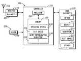
- the communication device 130includes a controller 210 and a receiver 240 coupled to the controller 210 .
- An alert device 275is coupled to the controller 210 .
- the alert device 275alerts a user 110 that the receiver 240 has received a communication.
- the alert device 275has a plurality of operating modes.
- the activity monitoring device 120monitors the activity of the user 110 , and senses a biometric characteristic of the user 110 .
- the controller 210selects one of the operating modes of the alert device 275 based on the sensed biometric characteristic of the user 110 . Therefore, for example, if the controller 210 determines that the user 110 is asleep, a silent mode of the alert device 275 can be selected and the user 110 will not be disturbed.
- the communication device 130 of FIG. 1is, for example, a wireless communication device but is not limited to a wireless communication device.
- the communication device 130 of FIG. 1can be, for example, a wired communication device, such as a wired telephone or a personal computer that alerts a user 110 when an e-mail message arrives.
- the communication device 130is a wireless communication device, and both a transmitter 250 and the receiver 240 are coupled to the controller 210 .
- the communication device 130 of FIG. 2is, for example, a cellular telephone.
- the alert device 275normally alerts the user 110 audibly when a call is received.
- An antenna 260is coupled to the receiver 240 and the transmitter 250 .
- the activity monitoring device 120is a motion sensor 280 , which is coupled to the controller 210 .
- the motion sensor 280is, for example, an infrared motion detector, such as those used conventionally in home security systems.
- the activity monitoring device 120may be any type of motion sensor that monitors activity of the user 110 .
- the activity monitoring device 120can be a sensor that monitors activity of the user 110 without contacting the user 110 .
- the activity monitoring device 120can be a heart rate sensor, wristwatch including biometric sensor, or other physical sensor that is attached directly to the user 110 .
- the senor 280may be a resistance sensor, for sensing electrical resistance of the user 110 , a solid state accelerometer, for detecting motion of the user, or other known motion sensor.
- the sensor 280may be connected to the controller 210 by a wire or by a wireless coupling such a short-range radio link.
- the sensor 280can be connected to the controller 210 with a wireless link, as described later in more detail.
- the controller 210includes a processor 220 , which is coupled to a memory 230 .
- the memory 230stores an operating system 232 , which, as is generally known in the art, is software for operating the controller 210 , and databases 234 , for storing various data required to operate the controller 210 .
- the memory 230stores an alert determination subroutine 236 , which is described in detail later, and other routines 238 for performing various functions of the communication device 130 .
- a user interface 270is coupled to the controller.
- the user interface 270includes at least a keypad 272 , a display 273 , a microphone 274 , the alert device 275 , and a speaker 276 .
- the alert device 275can be, for example, a sound generating apparatus such as a speaker for producing an audible alert. However, the alert device 275 may produce a tactile alert. In a manner that is understood by those of ordinary skill in the art, the volume and the pattern of the sound produced by the alert device 275 can be varied, and the device can be disabled so that no sound is produced. In the embodiment of FIG. 2 , the alert device 275 has at least two modes of operation. In a first mode of operation, the alert device 275 produces no audible sound.
- the first modeis a non-disturbing mode of the alert device 275 .
- the alert device 275produces audible sound.
- the first modeno tactile alert is produced and, in the second mode, the alert device 275 produces a tactile alert.
- the second mode of the alert devicemay be put into effect by disabling the alert device 275 .
- the alert determination routine 236determines which of the alert modes is used if an incoming call is received by the receiver 240 .
- the sensor 280produces signals that represent the activity level of the user 110 .
- the processor 220reads the signals and determines whether the activity level of the user 110 is less than a predetermined activity level. If the activity level of the user 110 is less than the predetermined activity level, the processor 220 selects the first mode, or the non-disturbing mode, of the alert device 275 . That is, in one embodiment, a silent mode of the alert device 275 is selected. Otherwise, the processor 220 selects an audible or other mode of the alert device 275 .
- FIG. 3illustrates a further embodiment of the communication apparatus.
- the embodiment of FIG. 3includes a communication device 130 , which is essentially the same as that of the embodiment of FIG. 1 .
- the embodiment of FIG. 3differs from that of FIG. 1 in that the communication device 130 includes a short-range receiver 392 for coupling the activity monitoring device 120 to the controller 210 .
- the activity monitoring device 120 in the embodiment of FIG. 3includes a short-range transmitter 394 that communicates with the short-range receiver 392 .
- the short-range wireless link formed by the short-range transmitter 394 and the short-range receiver 392operates with a conventional communication standard such as Bluetooth.
- a sensor 395is coupled to the short-range transmitter 394 .
- the sensor 395like the sensor 280 of the embodiment of FIG. 2 , senses the activity of the user 110 .
- the sensor 395can be a motion detector, such as an infrared motion detector, that can detect motion of the user 110 without contacting the user 110 .
- the sensor 395can be a sensor that is attached directly to the user 110 for sensing a physical characteristic such as heart rate.
- the sensor 395produces signals that represent the activity level of the user 110 .
- the signalsare transmitted by the short-range transmitter 394 , which has an antenna 398 , to the short-range receiver 392 , which has an antenna 393 .
- the processor 220reads the signals from the short-range receiver 392 and determines whether the activity level of the user 110 is less than a predetermined activity level. If the activity level of the user 110 is less than the predetermined activity level, the processor 220 selects the non-disturbing mode, or the first mode, of the alert device 275 . Otherwise, the processor 220 selects the second mode of the alert device 275 , in which the user 110 is alerted to incoming calls.
- FIG. 4illustrates the communication device 130 of FIG. 3 in operation when the sensor 395 of the activity monitoring device 120 is a heart rate sensor that is attached directly to the user 110 .
- a wire 410couples the heart rate sensor 395 to the short-range transmitter 394 .
- Signals representing the heart rate of the user 110are sent wirelessly to the communication device 130 with the short-range transmitter 394 and the short-range receiver 392 .
- the signalsare analyzed by the processor 220 to determine whether the activity level of the user 110 is less than a predetermined level.
- FIG. 5illustrates the communication device 130 of FIG. while in operation when the sensor 395 of the activity monitoring device 120 is a non-contacting motion sensor.
- a small permanent magnet 510which has North-seeking and South-seeking poles, is attached to the clothing of the user 110 .
- the magnet 510is located such that is will move in accordance with the motion of the user's chest or abdomen during breathing.
- the magnet 510may be held in a pouch that includes a fastener for readily attaching the magnet 510 to the user's clothing.
- the sensor 395which is located inside the activity monitoring device 120 , as indicated in FIG. 3 , is a transducer type of sensor for magnetic fields, such as a Hall effect device, a magnetostrictive transducer, a magnetic field sensitive transistor, a search coil, a fluxgate transducer, or other device for sensing and measuring magnetic field intensity.
- the sensor 395provides an electrical output signal indicative of the magnetic field strength present in the immediate vicinity of the sensor 395 .
- the sensor 395is mounted in a relatively fixed location proximate to where the user 110 sleeps.
- the activity monitoring device 120which includes the sensor 395 , may be located beneath the bed of the user 110 .
- This locationis suggested, since it places the sensor 395 in close proximity to the magnet 510 .
- the sensitivity required by the sensor 395is reduced when the distance between the magnet 510 and the sensor 395 is reduced, and the lower the required sensitivity of the sensor 395 , the lower the cost.
- the sensor 395provides an electrical output signal indicative of the magnetic field strength present in the immediate vicinity of the sensor 395 .
- the magnet 510will move causing the distance between the magnet 510 and the sensor 395 to vary.
- the output signal of the sensor 395will have a variable component due to the motion of the magnet 510 .
- the variable componentcan be separated out for further processing by using well-known techniques such as analog filtering or by analog to digital conversion and thereafter using digital filtering, such that the sensor 395 produces signals that represent the breathing of the user 110 .
- the signals representing the breathing of the user 110are sent to the short-range transmitter 394 and are transmitted to the short-range receiver 392 of the communication device 130 .
- the processor 220reads the signals and determines whether to employ the non-disturbing mode of the alert device 275 . That is, the processor 220 determines whether the user 110 is in a state of sleep and selects the first, or non-disturbing, alert mode if the user 110 is determined to be in a state of sleep.
- FIG. 6illustrates the method of selecting an alert mode in more detail in the form of an alert determination subroutine 236 , which is stored in the memory 230 .
- the activity of the user 110is sensed at 610 .
- signalswhich are produced by the sensor 280 of FIG. 2 or sensor 395 of FIG. 3 , are read by the processor 220 .
- the signalsare analyzed to determine the activity level of the user 110 . For example, if the signals represent the heart beat of the user 110 , the processor 220 determines the heart rate of the user 110 .
- the processor 220determines whether the activity level of the user 110 is less than a predetermined level.
- the current heart rateis compared to a predetermined heart rate, which is determined experimentally or is taken from reference sources such as medical textbooks.
- the predetermined heart rateis stored, for example, in a database 234 and is used to judge, for example, whether the user 110 is sleeping. If the outcome of the decision 614 is positive, then at 618 , the processor 220 determines that the user 110 is in a first state, or in a state of sleep, and the first alert mode, or a non-disturbing alert mode, is employed. That is, for example, a silent mode of the alert device 275 is selected by the processor 220 if the user 110 is considered to be sleeping.
- the processor 220determines that the user 110 is in a second state, or in a wakeful state, and a second alert mode is employed. That is, for example, an audible mode of the alert device 275 is selected by the processor 220 .
- the processor 220may select the alert mode by, for example, setting a flag that is stored in a database 234 in a manner well understood by those of ordinary skill in the art.
- the flagis referred to by the operating system 232 of the communication device 130 . That is, the state of the flag determines the current alert mode.
- heart ratewas used as an exemplary biometric characteristic in discussing the flow chart of FIG. 6
- other biometricsmay be employed to determine the activity level of the user 110 as is apparent from the discussion of the embodiment of FIG. 5 , in which a motion detector is employed to measure chest movement. That is, the processor 220 may determine whether the user 110 is in a state of sleep based on whether the frequency of chest movement is less than a predetermined frequency.
- the sensor 395may be a conventional infrared motion detector, which is employed to produce signals representative of the user's chest or abdominal movement.
- the sensor 395may be a commercially available solid state accelerometer. In this case, the accelerometer is attached to the bed or the clothing of the user 110 .
- the accelerometermay be coupled by wire or wirelessly linked to the short range transmitter 394 . Output signals from the accelerometer can be used to determine the degree or frequency of physical movement of the user in the same manner as signals from other types of motion detectors.
- the senor 395includes a pair of electrodes, such as transcutaneous, electrical nerve stimulation, or TENS, electrodes, which measure the electrical resistance of the user 110 . Electrodes measuring resistance are used because this is relatively non-invasive and easy for one to attach before going to bed. Besides electrical resistance, other data and other sensors commonly used by sleep researchers to determine sleep stages of subjects can also be used, as is readily understood by one of ordinary skill in the art.
- TENStranscutaneous, electrical nerve stimulation
- the “spikes,” which are referred to as optimal wake up points,can be detected through changes in the resistance sensed by the sensor 395 .
- the processor 220not only selects the audible mode of the alert device when the user 110 is determined to be awake but also selects the audible alert mode when one of the optimal wake-up points is reached.
- the communication device 130judges whether the user 110 is awake or in a light state of sleep and selects the audible alert mode if the user 110 is awake or in a light state of sleep.
- signals representing the electrical resistance of the user 110are sent to the processor 220 by the activity monitoring device 120 . It has been determined that a sharp drop in resistance occurs at the optimal wake up times.
- the processor 220is programmed to look at the electrical resistance of the user 110 at intervals of, for example, every three seconds and to review, for example, the previous thirty seconds for trend information. The amount of change in the resistance value at each three second interval over the previous thirty second period is stored and compared to a predetermined value, which is a threshold for determining whether to select the audible alert mode of the communication device 130 . For example, if a 5% change or greater occurs in the resistance over the previous thirty second period, the processor 220 selects the audible alert mode of the alert device 275 .
- the sample times and intervalscan be adjusted according to the user 110 to achieve optimal results. Further, other known methods of detecting spikes in data can be employed with equal effect. In addition, further computer analysis of the spikes may be performed to determine whether a given spike indicates a period of light sleep.
- the processor 220may be programmed such that, after a certain time period, the processor 220 again selects the silent alert mode as long as the user 110 is determined to be asleep. Therefore, if the user 110 is determined to be awake or in a light state of sleep, the audible alert mode will be selected, and the communication device 130 will produce an audible sound if an incoming call is received.
- FIG. 7shows the method just described in more detail.
- the routine of FIG. 7can be stored in the memory 230 of FIG. 3 as an alert determination subroutine 236 .
- the electrical resistance of the user 110is sensed at short intervals (three second intervals in this embodiment).
- the resistance signalsare transmitted to the short-range receiver 392 by the short-range transmitter 394 of the activity monitoring device 120 , and the signals for a period of time during which trends will be observed (thirty seconds in this embodiment) are read and stored by the processor 220 .
- the processor 220determines the rate of change of the resistance over the previous thirty second period.
- a decision 714it is determined whether the rate of change of resistance is less than a predetermined rate (5% in this embodiment). If the outcome is positive, the user 110 is determined to be asleep, or in a first state, at 718 , and the first alert mode, or a silent alert mode, is selected. If the outcome is negative, then a spike in the user's electrical resistance has been detected and, at 716 , the user 110 is considered to be awake or in a light state of sleep, or in a second state, and the second alert mode, or the audible alert mode, is selected.
- a predetermined rate5% in this embodiment
Landscapes
- Engineering & Computer Science (AREA)
- Human Computer Interaction (AREA)
- Physics & Mathematics (AREA)
- General Physics & Mathematics (AREA)
- Emergency Management (AREA)
- Environmental & Geological Engineering (AREA)
- Business, Economics & Management (AREA)
- Computer Networks & Wireless Communication (AREA)
- Signal Processing (AREA)
- Measuring And Recording Apparatus For Diagnosis (AREA)
- Alarm Systems (AREA)
- Mobile Radio Communication Systems (AREA)
- Telephone Function (AREA)
- Emergency Alarm Devices (AREA)
Abstract
Description
Claims (19)
Priority Applications (8)
| Application Number | Priority Date | Filing Date | Title |
|---|---|---|---|
| US10/686,085US7170994B2 (en) | 2003-10-15 | 2003-10-15 | Method and apparatus for selecting an alert mode based on user biometrics |
| ES04821294.8TES2661300T3 (en) | 2003-10-15 | 2004-09-30 | Method and apparatus for selecting an alert mode based on the user's biometric information |
| EP17200307.1AEP3300343B1 (en) | 2003-10-15 | 2004-09-30 | Method and apparatus for selecting an alert mode based on user biometrics |
| PCT/US2004/031508WO2005074427A2 (en) | 2003-10-15 | 2004-09-30 | Method and apparatus for selecting an alert mode based on user biometrics |
| CN200480030066XACN101263701B (en) | 2003-10-15 | 2004-09-30 | Method and apparatus for selecting an alert mode based on user biometrics |
| RU2006116519/09ARU2380855C2 (en) | 2003-10-15 | 2004-09-30 | Method and device for warning mode selection on basis of user biometrics |
| EP04821294.8AEP1721447B1 (en) | 2003-10-15 | 2004-09-30 | Method and apparatus for selecting an alert mode based on user biometrics |
| KR1020067007258AKR101067043B1 (en) | 2003-10-15 | 2004-09-30 | Method and apparatus for selecting an alarm mode based on user biometrics |
Applications Claiming Priority (1)
| Application Number | Priority Date | Filing Date | Title |
|---|---|---|---|
| US10/686,085US7170994B2 (en) | 2003-10-15 | 2003-10-15 | Method and apparatus for selecting an alert mode based on user biometrics |
Publications (2)
| Publication Number | Publication Date |
|---|---|
| US20050084075A1 US20050084075A1 (en) | 2005-04-21 |
| US7170994B2true US7170994B2 (en) | 2007-01-30 |
Family
ID=34520710
Family Applications (1)
| Application Number | Title | Priority Date | Filing Date |
|---|---|---|---|
| US10/686,085Expired - LifetimeUS7170994B2 (en) | 2003-10-15 | 2003-10-15 | Method and apparatus for selecting an alert mode based on user biometrics |
Country Status (7)
| Country | Link |
|---|---|
| US (1) | US7170994B2 (en) |
| EP (2) | EP3300343B1 (en) |
| KR (1) | KR101067043B1 (en) |
| CN (1) | CN101263701B (en) |
| ES (1) | ES2661300T3 (en) |
| RU (1) | RU2380855C2 (en) |
| WO (1) | WO2005074427A2 (en) |
Cited By (2)
| Publication number | Priority date | Publication date | Assignee | Title |
|---|---|---|---|---|
| US20070100666A1 (en)* | 2002-08-22 | 2007-05-03 | Stivoric John M | Devices and systems for contextual and physiological-based detection, monitoring, reporting, entertainment, and control of other devices |
| US20130276143A1 (en)* | 2010-12-30 | 2013-10-17 | Telefonaktiebolaget L M Ericsson (Publ) | Biometric User Equipment GUI Trigger |
Families Citing this family (35)
| Publication number | Priority date | Publication date | Assignee | Title |
|---|---|---|---|---|
| US7912185B2 (en)* | 2001-03-09 | 2011-03-22 | Celphinder Technologies, Inc. | System and method for providing the precise location of a cell phone making an emergency call |
| US7299034B2 (en)* | 2005-06-21 | 2007-11-20 | Lawrence Kates | System and method for wearable electronics |
| US7688181B2 (en)* | 2006-09-06 | 2010-03-30 | Savi Technology, Inc. | Method and apparatus for avoiding overpolling |
| US8761846B2 (en)* | 2007-04-04 | 2014-06-24 | Motorola Mobility Llc | Method and apparatus for controlling a skin texture surface on a device |
| US20090015547A1 (en)* | 2007-07-12 | 2009-01-15 | Franz Roger L | Electronic Device with Physical Alert |
| US8275373B2 (en)* | 2007-09-28 | 2012-09-25 | Qualcomm Incorporated | Randomization of periodic channel scans |
| US20100022279A1 (en)* | 2008-07-22 | 2010-01-28 | Sony Ericsson Mobile Communications Ab | Mood dependent alert signals in communication devices |
| DE102008056251A1 (en)* | 2008-10-07 | 2010-04-15 | Fraunhofer-Gesellschaft zur Förderung der angewandten Forschung e.V. | Device and method for detecting a vital parameter |
| DE102008056252A1 (en) | 2008-10-07 | 2010-04-15 | Fraunhofer-Gesellschaft zur Förderung der angewandten Forschung e.V. | Apparatus and method for detecting a respiration of a living being |
| US9152768B2 (en)* | 2011-09-26 | 2015-10-06 | Hill-Rom Services, Inc. | Method and system for patient care management |
| CN103138807B (en)* | 2011-11-28 | 2014-11-26 | 财付通支付科技有限公司 | Implement method and system for near field communication (NFC) |
| WO2013109947A1 (en)* | 2012-01-19 | 2013-07-25 | Nike International Ltd. | Wearable device assembly having solder mask |
| TWI512539B (en)* | 2012-03-30 | 2015-12-11 | Hon Hai Prec Ind Co Ltd | Mode management system and management method thereof |
| US9454208B2 (en) | 2013-03-14 | 2016-09-27 | Google Inc. | Preventing sleep mode for devices based on sensor inputs |
| EP2968045A4 (en)* | 2013-03-15 | 2016-11-16 | Stryker Corp | PATIENT SUPPORT APPARATUS HAVING PATIENT INFORMATION SENSORS |
| KR101465579B1 (en)* | 2013-05-03 | 2014-11-27 | 주식회사 엔솔브 | System for baby-sitter interlocked exterior system |
| US9892612B2 (en)* | 2013-12-20 | 2018-02-13 | Koninklijke Philips N.V. | Method for responding to a detected fall and an apparatus for implementing the same |
| JP6421413B2 (en)* | 2013-12-20 | 2018-11-14 | カシオ計算機株式会社 | Electronic device, output control system, output control method and program |
| CN103870220A (en)* | 2014-03-19 | 2014-06-18 | 惠州Tcl移动通信有限公司 | Control method and control system for working modes of mobile device |
| CN104092830A (en)* | 2014-07-21 | 2014-10-08 | 上海斐讯数据通信技术有限公司 | Method and system for setting working modes of mobile phone automatically |
| CN104104927B (en)* | 2014-07-30 | 2017-11-14 | 天津三星电子有限公司 | A kind of baby's monitoring and reminding method and system based on TV |
| CN105577898A (en)* | 2014-10-15 | 2016-05-11 | 昆山研达电脑科技有限公司 | System and method for turning on no-disturbing mode of mobile phone automatically |
| CN106999108A (en)* | 2014-12-10 | 2017-08-01 | 皇家飞利浦有限公司 | System and method for falling detection |
| WO2016090630A1 (en)* | 2014-12-12 | 2016-06-16 | Intel Corporation | Configure smartphone based on user sleep status |
| KR20160080473A (en)* | 2014-12-29 | 2016-07-08 | 엘지전자 주식회사 | Watch type mobile terminal and method of controlling the same |
| CN104767883B (en)* | 2015-03-25 | 2018-03-27 | 广东欧珀移动通信有限公司 | The method and terminal of a kind of terminal notifying |
| CN104873170B (en)* | 2015-04-20 | 2018-11-27 | 广东欧珀移动通信有限公司 | The method, apparatus and smartwatch of prompting message |
| US10070323B2 (en)* | 2015-09-02 | 2018-09-04 | Motorola Mobility Llc | Method and apparatus for managing a nap mode on an electronic device |
| CN105554237A (en)* | 2015-09-29 | 2016-05-04 | 宇龙计算机通信科技(深圳)有限公司 | Anti-disturb mode management method and user terminal |
| CN106973176A (en)* | 2016-01-14 | 2017-07-21 | 株式会社东芝 | Image processing system |
| CN105827864A (en)* | 2016-05-13 | 2016-08-03 | 珠海市魅族科技有限公司 | Method and device for processing communication request, and intelligent device |
| CN106773806A (en)* | 2016-11-18 | 2017-05-31 | 深圳市欧瑞博电子有限公司 | Prompting control method and system |
| CN106789187A (en)* | 2016-12-02 | 2017-05-31 | 国网北京市电力公司 | The method and system of power distribution network alarm management |
| US10492696B2 (en) | 2017-06-09 | 2019-12-03 | Anthony Olivero | Portable biometric monitoring device and method for use thereof |
| US11950886B2 (en) | 2017-06-09 | 2024-04-09 | Anthony Olivero | Apparatus and method for providing remote health care recommendations using a passive health care monitoring device |
Citations (48)
| Publication number | Priority date | Publication date | Assignee | Title |
|---|---|---|---|---|
| US3884218A (en) | 1970-09-30 | 1975-05-20 | Monroe Ind Inc | Method of inducing and maintaining various stages of sleep in the human being |
| US4228806A (en) | 1978-05-25 | 1980-10-21 | International Rectifier Corporation | Sleep state inhibited wake-up alarm |
| US4550736A (en) | 1983-10-14 | 1985-11-05 | Canadian Patents & Development Limited | Movement artifact detector for sleep analysis |
| US4585011A (en) | 1983-10-14 | 1986-04-29 | Canadian Patents & Development Limited | Conjugate eye movement detector for sleep analysis |
| US4735199A (en) | 1986-01-14 | 1988-04-05 | Dilullo John D | Dream detection method and system |
| US4832050A (en) | 1986-01-14 | 1989-05-23 | Dilullo John D | Motion sensor |
| US4836219A (en) | 1987-07-08 | 1989-06-06 | President & Fellows Of Harvard College | Electronic sleep monitor headgear |
| US4863259A (en) | 1988-03-09 | 1989-09-05 | Schneider Michael B | Rapid eye movement sleep state detector |
| US5008865A (en) | 1988-07-20 | 1991-04-16 | Blaine P. Shaffer | Light source with gradually changing intensity |
| WO1991009372A1 (en) | 1989-12-13 | 1991-06-27 | Bio-Logic Systems Corporation | Computer assisted analysis of sleep |
| EP0450341A2 (en) | 1990-04-05 | 1991-10-09 | Hewlett-Packard Company | Cardiac analyzer with rem sleep detection |
| WO1991016853A1 (en) | 1990-05-10 | 1991-11-14 | Hearne, Bobbi, Lynn | Dream machine |
| US5101831A (en) | 1989-07-07 | 1992-04-07 | Matsushita Electric Works, Ltd. | System for discriminating sleep state |
| WO1993008739A1 (en) | 1991-10-29 | 1993-05-13 | Brigham And Women's Hospital | Alertness monitor |
| US5280791A (en) | 1991-11-19 | 1994-01-25 | The Sleep Disorders Diagnostic And Treatment Center, Ltd. | Monitor system for determining the sleep stages of a person |
| WO1995000001A1 (en) | 1993-06-23 | 1995-01-05 | Aequitron Medical, Inc. | Iterative sleep evaluation |
| EP0652496A1 (en) | 1993-05-21 | 1995-05-10 | Seiko Epson Corporation | Dial of timepiece and timepiece |
| US5441476A (en) | 1992-05-22 | 1995-08-15 | Matsushita Electric Works, Ltd. | Body temperature regulation system |
| WO1995033403A1 (en) | 1994-06-07 | 1995-12-14 | Gaby Bader | Method and apparatus for monitoring and estimating the awakeness of a person |
| US5507716A (en) | 1991-08-21 | 1996-04-16 | The Lucidity Institute, Inc. | Equipment and methods used to induce lucid dreams in sleeping persons |
| US5551879A (en) | 1994-09-16 | 1996-09-03 | Dream Weaver J.V. | Dream state teaching machine |
| WO1997017012A1 (en) | 1995-11-09 | 1997-05-15 | Del Mar Avionics | Modular physiological computer-recorder |
| WO1997038359A1 (en) | 1996-04-06 | 1997-10-16 | GÜSE, Klaus | Method and device for waking people sleeping in a given state of sleep |
| EP0845241A1 (en) | 1996-06-12 | 1998-06-03 | Seiko Epson Corporation | Consumed calorie measuring apparatus and body temperature measuring apparatus |
| US5772591A (en) | 1995-06-06 | 1998-06-30 | Patient Comfort, Inc. | Electrode assembly for signaling a monitor |
| WO1998043536A1 (en) | 1997-03-31 | 1998-10-08 | President And Fellows Of Harvard College | Home-based system and method for monitoring sleep state and assessing cardiorespiratory risk |
| US5825293A (en) | 1996-09-20 | 1998-10-20 | Ahmed; Adel A. | Apparatus and method for monitoring breathing magnetically |
| WO1998049028A1 (en) | 1997-04-25 | 1998-11-05 | Applied Science Group, Inc. | An alertness monitor |
| WO1998053456A1 (en) | 1997-05-19 | 1998-11-26 | Creator Ltd. | Apparatus and methods for controlling household appliances |
| US5928133A (en) | 1997-01-30 | 1999-07-27 | Halyak; George | User responsive sleep monitoring and awakening device |
| US5948303A (en) | 1998-05-04 | 1999-09-07 | Larson; Lynn D. | Temperature control for a bed |
| WO2000072748A1 (en) | 1999-05-27 | 2000-12-07 | Flock Stephen T | Optical monitor of anatomical movement |
| EP1059575A2 (en) | 1999-06-08 | 2000-12-13 | Yumex Co., Ltd. | Alarm clock and alarm clock simulating indicator |
| WO2001003751A2 (en) | 1999-07-09 | 2001-01-18 | Cornell Research Foundation, Inc. | Rem sleep augmentation with extra-ocular light |
| US6231187B1 (en) | 1999-02-11 | 2001-05-15 | Queen's University At Kingston | Method and apparatus for detecting eye movement |
| WO2001050202A1 (en) | 2000-01-03 | 2001-07-12 | Yael Vons Jarzen | Timepiece with novel hands |
| US6272378B1 (en) | 1996-11-21 | 2001-08-07 | 2Rcw Gmbh | Device and method for determining sleep profiles |
| WO2001064101A1 (en) | 2000-03-02 | 2001-09-07 | Itamar Medical Ltd. | Method and apparatus for the non-invasive detection of particular sleep-state conditions by monitoring the peripheral vascular system |
| US6319205B1 (en) | 1996-07-30 | 2001-11-20 | Itamar Medical (C.M.) 1997 Ltd. | Method and apparatus for the non-invasive detection of medical conditions by monitoring peripheral arterial tone |
| US20010048639A1 (en) | 2000-01-04 | 2001-12-06 | Davidson Daniel L. | System for monitoring, processing, and presenting sleep time data |
| WO2001091631A1 (en) | 2000-05-29 | 2001-12-06 | Richard Hamilton Lewis | A sleep study apparatus |
| WO2001095803A1 (en) | 2000-06-15 | 2001-12-20 | The Procter & Gamble Company | System for body activity detection and processing |
| WO2001095801A1 (en) | 2000-06-15 | 2001-12-20 | The Procter & Gamble Company | Device for body activity detection and processing |
| WO2001095802A1 (en) | 2000-06-15 | 2001-12-20 | The Procter & Gamble Company | Body activity detection and processing |
| WO2001098842A1 (en) | 2000-06-22 | 2001-12-27 | Koninklijke Philips Electronics N.V. | System for awaking a user |
| US20020029000A1 (en) | 2000-09-07 | 2002-03-07 | Rie Ohsaki | Method for detecting physiological condition of sleeping patient based on analysis of pulse waves |
| US20030174049A1 (en)* | 2002-03-18 | 2003-09-18 | Precision Dynamics Corporation | Wearable identification appliance that communicates with a wireless communications network such as bluetooth |
| US20040066932A1 (en)* | 2002-05-06 | 2004-04-08 | Seligmann Doree Duncan | Intelligent multimode message alerts |
Family Cites Families (9)
| Publication number | Priority date | Publication date | Assignee | Title |
|---|---|---|---|---|
| KR100197580B1 (en) | 1995-09-13 | 1999-06-15 | 이민화 | A living body monitoring system making use of wireless netwokk |
| US20010031633A1 (en)* | 1999-12-01 | 2001-10-18 | Nokia Mobile Phones Ltd. | Method and apparatus for providing context-based call transfer operation |
| GB2357400A (en)* | 1999-12-17 | 2001-06-20 | Nokia Mobile Phones Ltd | Controlling a terminal of a communication system |
| JP2001197990A (en) | 2000-01-19 | 2001-07-24 | Kunihiro Okada | Pillow provided with detector having alarming means |
| US6954657B2 (en)* | 2000-06-30 | 2005-10-11 | Texas Instruments Incorporated | Wireless communication device having intelligent alerting system |
| US6973336B2 (en)* | 2000-12-20 | 2005-12-06 | Nokia Corp | Method and apparatus for providing a notification of received message |
| US20020077086A1 (en)* | 2000-12-20 | 2002-06-20 | Nokia Mobile Phones Ltd | Method and apparatus for using DTMF for controlling context calls, and mutual context information exchange during mobile communication |
| DE10140968A1 (en)* | 2001-08-27 | 2003-04-03 | Vitaphone Gmbh | Method, device and system for measuring and transmitting functional values of bodily functions |
| US6912386B1 (en)* | 2001-11-13 | 2005-06-28 | Nokia Corporation | Method for controlling operation of a mobile device by detecting usage situations |
- 2003
- 2003-10-15USUS10/686,085patent/US7170994B2/ennot_activeExpired - Lifetime
- 2004
- 2004-09-30WOPCT/US2004/031508patent/WO2005074427A2/enactiveApplication Filing
- 2004-09-30CNCN200480030066XApatent/CN101263701B/ennot_activeExpired - Lifetime
- 2004-09-30EPEP17200307.1Apatent/EP3300343B1/ennot_activeExpired - Lifetime
- 2004-09-30EPEP04821294.8Apatent/EP1721447B1/ennot_activeExpired - Lifetime
- 2004-09-30KRKR1020067007258Apatent/KR101067043B1/ennot_activeExpired - Lifetime
- 2004-09-30RURU2006116519/09Apatent/RU2380855C2/enactive
- 2004-09-30ESES04821294.8Tpatent/ES2661300T3/ennot_activeExpired - Lifetime
Patent Citations (59)
| Publication number | Priority date | Publication date | Assignee | Title |
|---|---|---|---|---|
| US3884218A (en) | 1970-09-30 | 1975-05-20 | Monroe Ind Inc | Method of inducing and maintaining various stages of sleep in the human being |
| US4228806A (en) | 1978-05-25 | 1980-10-21 | International Rectifier Corporation | Sleep state inhibited wake-up alarm |
| US4550736A (en) | 1983-10-14 | 1985-11-05 | Canadian Patents & Development Limited | Movement artifact detector for sleep analysis |
| US4585011A (en) | 1983-10-14 | 1986-04-29 | Canadian Patents & Development Limited | Conjugate eye movement detector for sleep analysis |
| US4735199A (en) | 1986-01-14 | 1988-04-05 | Dilullo John D | Dream detection method and system |
| US4832050A (en) | 1986-01-14 | 1989-05-23 | Dilullo John D | Motion sensor |
| US4836219A (en) | 1987-07-08 | 1989-06-06 | President & Fellows Of Harvard College | Electronic sleep monitor headgear |
| WO1989008423A1 (en) | 1988-03-09 | 1989-09-21 | Schneider Michael B | Rapid eye movement sleep state detector |
| US4863259A (en) | 1988-03-09 | 1989-09-05 | Schneider Michael B | Rapid eye movement sleep state detector |
| US5008865A (en) | 1988-07-20 | 1991-04-16 | Blaine P. Shaffer | Light source with gradually changing intensity |
| US5101831A (en) | 1989-07-07 | 1992-04-07 | Matsushita Electric Works, Ltd. | System for discriminating sleep state |
| WO1991009372A1 (en) | 1989-12-13 | 1991-06-27 | Bio-Logic Systems Corporation | Computer assisted analysis of sleep |
| EP0450341B1 (en) | 1990-04-05 | 1995-12-20 | Hewlett-Packard Company | Cardiac analyzer with rem sleep detection |
| EP0450341A2 (en) | 1990-04-05 | 1991-10-09 | Hewlett-Packard Company | Cardiac analyzer with rem sleep detection |
| US5187657A (en) | 1990-04-05 | 1993-02-16 | Hewlett-Packard Company | Cardiac analyzer with rem sleep detection |
| WO1991016853A1 (en) | 1990-05-10 | 1991-11-14 | Hearne, Bobbi, Lynn | Dream machine |
| US5507716A (en) | 1991-08-21 | 1996-04-16 | The Lucidity Institute, Inc. | Equipment and methods used to induce lucid dreams in sleeping persons |
| WO1993008739A1 (en) | 1991-10-29 | 1993-05-13 | Brigham And Women's Hospital | Alertness monitor |
| US5280791A (en) | 1991-11-19 | 1994-01-25 | The Sleep Disorders Diagnostic And Treatment Center, Ltd. | Monitor system for determining the sleep stages of a person |
| US5441476A (en) | 1992-05-22 | 1995-08-15 | Matsushita Electric Works, Ltd. | Body temperature regulation system |
| EP0652496A1 (en) | 1993-05-21 | 1995-05-10 | Seiko Epson Corporation | Dial of timepiece and timepiece |
| EP0652496B1 (en) | 1993-05-21 | 1999-07-21 | Seiko Epson Corporation | Dial of timepiece and timepiece |
| WO1995000001A1 (en) | 1993-06-23 | 1995-01-05 | Aequitron Medical, Inc. | Iterative sleep evaluation |
| US5846206A (en) | 1994-06-07 | 1998-12-08 | Biosys Ab | Method and apparatus for monitoring and estimating the awakeness of a person |
| WO1995033403A1 (en) | 1994-06-07 | 1995-12-14 | Gaby Bader | Method and apparatus for monitoring and estimating the awakeness of a person |
| US5551879A (en) | 1994-09-16 | 1996-09-03 | Dream Weaver J.V. | Dream state teaching machine |
| US5772591A (en) | 1995-06-06 | 1998-06-30 | Patient Comfort, Inc. | Electrode assembly for signaling a monitor |
| WO1997017012A1 (en) | 1995-11-09 | 1997-05-15 | Del Mar Avionics | Modular physiological computer-recorder |
| WO1997038359A1 (en) | 1996-04-06 | 1997-10-16 | GÜSE, Klaus | Method and device for waking people sleeping in a given state of sleep |
| US6030342A (en) | 1996-06-12 | 2000-02-29 | Seiko Epson Corporation | Device for measuring calorie expenditure and device for measuring body temperature |
| US6287262B1 (en) | 1996-06-12 | 2001-09-11 | Seiko Epson Corporation | Device for measuring calorie expenditure and device for measuring body temperature |
| EP0845241A1 (en) | 1996-06-12 | 1998-06-03 | Seiko Epson Corporation | Consumed calorie measuring apparatus and body temperature measuring apparatus |
| US6319205B1 (en) | 1996-07-30 | 2001-11-20 | Itamar Medical (C.M.) 1997 Ltd. | Method and apparatus for the non-invasive detection of medical conditions by monitoring peripheral arterial tone |
| US6322515B1 (en) | 1996-07-30 | 2001-11-27 | Itamar Medical | Method and apparatus for the non-invasive detection of medical conditions by monitoring peripheral arterial tone |
| US5825293A (en) | 1996-09-20 | 1998-10-20 | Ahmed; Adel A. | Apparatus and method for monitoring breathing magnetically |
| US6272378B1 (en) | 1996-11-21 | 2001-08-07 | 2Rcw Gmbh | Device and method for determining sleep profiles |
| US5928133A (en) | 1997-01-30 | 1999-07-27 | Halyak; George | User responsive sleep monitoring and awakening device |
| WO1998043536A1 (en) | 1997-03-31 | 1998-10-08 | President And Fellows Of Harvard College | Home-based system and method for monitoring sleep state and assessing cardiorespiratory risk |
| WO1998049028A1 (en) | 1997-04-25 | 1998-11-05 | Applied Science Group, Inc. | An alertness monitor |
| WO1998053456A1 (en) | 1997-05-19 | 1998-11-26 | Creator Ltd. | Apparatus and methods for controlling household appliances |
| WO2001006921A1 (en) | 1998-03-23 | 2001-02-01 | George Halyak | User responsive sleep monitoring and awakening device |
| US5948303A (en) | 1998-05-04 | 1999-09-07 | Larson; Lynn D. | Temperature control for a bed |
| US6352517B1 (en) | 1998-06-02 | 2002-03-05 | Stephen Thomas Flock | Optical monitor of anatomical movement and uses thereof |
| US6231187B1 (en) | 1999-02-11 | 2001-05-15 | Queen's University At Kingston | Method and apparatus for detecting eye movement |
| WO2000072748A1 (en) | 1999-05-27 | 2000-12-07 | Flock Stephen T | Optical monitor of anatomical movement |
| EP1059575A2 (en) | 1999-06-08 | 2000-12-13 | Yumex Co., Ltd. | Alarm clock and alarm clock simulating indicator |
| WO2001003751A2 (en) | 1999-07-09 | 2001-01-18 | Cornell Research Foundation, Inc. | Rem sleep augmentation with extra-ocular light |
| WO2001050202A1 (en) | 2000-01-03 | 2001-07-12 | Yael Vons Jarzen | Timepiece with novel hands |
| US20010048639A1 (en) | 2000-01-04 | 2001-12-06 | Davidson Daniel L. | System for monitoring, processing, and presenting sleep time data |
| WO2001064101A1 (en) | 2000-03-02 | 2001-09-07 | Itamar Medical Ltd. | Method and apparatus for the non-invasive detection of particular sleep-state conditions by monitoring the peripheral vascular system |
| WO2001091631A1 (en) | 2000-05-29 | 2001-12-06 | Richard Hamilton Lewis | A sleep study apparatus |
| WO2001095803A1 (en) | 2000-06-15 | 2001-12-20 | The Procter & Gamble Company | System for body activity detection and processing |
| WO2001095802A1 (en) | 2000-06-15 | 2001-12-20 | The Procter & Gamble Company | Body activity detection and processing |
| WO2001095801A1 (en) | 2000-06-15 | 2001-12-20 | The Procter & Gamble Company | Device for body activity detection and processing |
| WO2001098842A1 (en) | 2000-06-22 | 2001-12-27 | Koninklijke Philips Electronics N.V. | System for awaking a user |
| US20020080035A1 (en) | 2000-06-22 | 2002-06-27 | Konstantin Youdenko | System for awaking a user |
| US20020029000A1 (en) | 2000-09-07 | 2002-03-07 | Rie Ohsaki | Method for detecting physiological condition of sleeping patient based on analysis of pulse waves |
| US20030174049A1 (en)* | 2002-03-18 | 2003-09-18 | Precision Dynamics Corporation | Wearable identification appliance that communicates with a wireless communications network such as bluetooth |
| US20040066932A1 (en)* | 2002-05-06 | 2004-04-08 | Seligmann Doree Duncan | Intelligent multimode message alerts |
Cited By (7)
| Publication number | Priority date | Publication date | Assignee | Title |
|---|---|---|---|---|
| US20070100666A1 (en)* | 2002-08-22 | 2007-05-03 | Stivoric John M | Devices and systems for contextual and physiological-based detection, monitoring, reporting, entertainment, and control of other devices |
| US20130276143A1 (en)* | 2010-12-30 | 2013-10-17 | Telefonaktiebolaget L M Ericsson (Publ) | Biometric User Equipment GUI Trigger |
| US9135466B2 (en)* | 2010-12-30 | 2015-09-15 | Telefonaktiebolaget L M Ericsson (Publ) | Biometric user equipment GUI trigger |
| USRE47372E1 (en)* | 2010-12-30 | 2019-04-30 | Telefonaktiebolaget Lm Ericsson (Publ) | Biometric user equipment GUI trigger |
| USRE48339E1 (en)* | 2010-12-30 | 2020-12-01 | Telefonaktiebolaget Lm Ericsson (Publ) | Biometric user equipment GUI trigger |
| USRE48875E1 (en)* | 2010-12-30 | 2022-01-04 | Telefonaktiebolaget Lm Ericsson (Publ) | Biometric user equipment GUI trigger |
| USRE49691E1 (en)* | 2010-12-30 | 2023-10-10 | Telefonaktiebolaget Lm Ericsson (Publ) | Biometric user equipment GUI trigger |
Also Published As
| Publication number | Publication date |
|---|---|
| EP3300343A1 (en) | 2018-03-28 |
| KR101067043B1 (en) | 2011-09-22 |
| RU2006116519A (en) | 2007-11-27 |
| WO2005074427A3 (en) | 2007-11-15 |
| EP1721447B1 (en) | 2017-11-08 |
| WO2005074427A2 (en) | 2005-08-18 |
| EP3300343B1 (en) | 2020-02-12 |
| CN101263701B (en) | 2012-06-20 |
| EP1721447A4 (en) | 2009-02-18 |
| KR20070019655A (en) | 2007-02-15 |
| CN101263701A (en) | 2008-09-10 |
| US20050084075A1 (en) | 2005-04-21 |
| EP1721447A2 (en) | 2006-11-15 |
| ES2661300T3 (en) | 2018-03-28 |
| RU2380855C2 (en) | 2010-01-27 |
Similar Documents
| Publication | Publication Date | Title |
|---|---|---|
| US7170994B2 (en) | Method and apparatus for selecting an alert mode based on user biometrics | |
| US6992580B2 (en) | Portable communication device and corresponding method of operation | |
| US8493220B2 (en) | Arrangement and method to wake up a sleeping subject at an advantageous time instant associated with natural arousal | |
| EP1494190B1 (en) | Mobile communication device and method for monitoring and transmitting of bio-data and environment-data in an emergency case | |
| JP5497015B2 (en) | Method and system for automatically updating avatar status to indicate user status | |
| US20040203673A1 (en) | Intelligent incoming message notification | |
| US20170127354A1 (en) | Wearable apparatus and network for communication therewith | |
| CN113094112A (en) | Method and apparatus for automatically adjusting notification operations based on changes in physical activity levels | |
| JP2005202810A (en) | Person monitoring system | |
| EP1505819B1 (en) | Portable terminal device and method of notifying an incoming call | |
| CN106686250A (en) | Reminding mode setting method and device of intelligent terminal and intelligent watch | |
| CN107240231A (en) | Event reminding method, device and system | |
| JP2012065178A (en) | Communication device and program | |
| CN109155807A (en) | Device and method for adjusting acoustical signal | |
| CN110634251B (en) | Asynchronous ringing method and device | |
| MXPA06004144A (en) | Method and apparatus for selecting an alert mode based on user biometrics | |
| JP2007054241A (en) | Mobile terminal device | |
| JP3810996B2 (en) | Terminal status disclosure method, terminal status disclosure system, and wireless communication terminal | |
| KR20050099444A (en) | Device and method for checking healthy using ear-phone connecting wireless terminal | |
| CN111343337B (en) | A kind of alarm clock application prompting method and device based on electric toothbrush | |
| CN106993245A (en) | Earphone and alcohol sensing system | |
| CN104994228B (en) | Method for intelligently switching incoming call reminding modes and intelligent terminal | |
| JP2022177692A (en) | Surveillance system, mobile terminal, and program | |
| WO2025195361A1 (en) | Blood pressure measurement method, electronic device, and storage medium | |
| JP2022177693A (en) | Watching system, watching person terminal, and program |
Legal Events
| Date | Code | Title | Description |
|---|---|---|---|
| AS | Assignment | Owner name:MOTOROLA, INC., ILLINOIS Free format text:ASSIGNMENT OF ASSIGNORS INTEREST;ASSIGNOR:KOTZIN, MICHAEL D.;REEL/FRAME:014618/0292 Effective date:20031015 | |
| STCF | Information on status: patent grant | Free format text:PATENTED CASE | |
| FPAY | Fee payment | Year of fee payment:4 | |
| AS | Assignment | Owner name:MOTOROLA MOBILITY, INC, ILLINOIS Free format text:ASSIGNMENT OF ASSIGNORS INTEREST;ASSIGNOR:MOTOROLA, INC;REEL/FRAME:025673/0558 Effective date:20100731 | |
| AS | Assignment | Owner name:MOTOROLA MOBILITY LLC, ILLINOIS Free format text:CHANGE OF NAME;ASSIGNOR:MOTOROLA MOBILITY, INC.;REEL/FRAME:029216/0282 Effective date:20120622 | |
| FPAY | Fee payment | Year of fee payment:8 | |
| AS | Assignment | Owner name:GOOGLE TECHNOLOGY HOLDINGS LLC, CALIFORNIA Free format text:ASSIGNMENT OF ASSIGNORS INTEREST;ASSIGNOR:MOTOROLA MOBILITY LLC;REEL/FRAME:034227/0095 Effective date:20141028 | |
| MAFP | Maintenance fee payment | Free format text:PAYMENT OF MAINTENANCE FEE, 12TH YEAR, LARGE ENTITY (ORIGINAL EVENT CODE: M1553) Year of fee payment:12 |