US7170571B2 - Liquid crystal display device with double metal layer source and drain electrodes and fabricating method thereof - Google Patents
Liquid crystal display device with double metal layer source and drain electrodes and fabricating method thereofDownload PDFInfo
- Publication number
- US7170571B2 US7170571B2US10/028,768US2876801AUS7170571B2US 7170571 B2US7170571 B2US 7170571B2US 2876801 AUS2876801 AUS 2876801AUS 7170571 B2US7170571 B2US 7170571B2
- Authority
- US
- United States
- Prior art keywords
- metal layer
- layer
- electrode
- over
- liquid crystal
- Prior art date
- Legal status (The legal status is an assumption and is not a legal conclusion. Google has not performed a legal analysis and makes no representation as to the accuracy of the status listed.)
- Expired - Lifetime
Links
Images


Classifications
- G—PHYSICS
- G02—OPTICS
- G02F—OPTICAL DEVICES OR ARRANGEMENTS FOR THE CONTROL OF LIGHT BY MODIFICATION OF THE OPTICAL PROPERTIES OF THE MEDIA OF THE ELEMENTS INVOLVED THEREIN; NON-LINEAR OPTICS; FREQUENCY-CHANGING OF LIGHT; OPTICAL LOGIC ELEMENTS; OPTICAL ANALOGUE/DIGITAL CONVERTERS
- G02F1/00—Devices or arrangements for the control of the intensity, colour, phase, polarisation or direction of light arriving from an independent light source, e.g. switching, gating or modulating; Non-linear optics
- G02F1/01—Devices or arrangements for the control of the intensity, colour, phase, polarisation or direction of light arriving from an independent light source, e.g. switching, gating or modulating; Non-linear optics for the control of the intensity, phase, polarisation or colour
- G02F1/13—Devices or arrangements for the control of the intensity, colour, phase, polarisation or direction of light arriving from an independent light source, e.g. switching, gating or modulating; Non-linear optics for the control of the intensity, phase, polarisation or colour based on liquid crystals, e.g. single liquid crystal display cells
- G02F1/133—Constructional arrangements; Operation of liquid crystal cells; Circuit arrangements
- G02F1/136—Liquid crystal cells structurally associated with a semi-conducting layer or substrate, e.g. cells forming part of an integrated circuit
- G02F1/1362—Active matrix addressed cells
- G02F1/1368—Active matrix addressed cells in which the switching element is a three-electrode device
Definitions
- This inventionrelates to a liquid crystal display, and more particularly, a liquid crystal display device and a fabricating method thereof with double metal layer source and drain electrodes.
- a liquid crystal displaycontrols light transmittance using an electric field to display a picture.
- the LCDincludes a liquid crystal panel having liquid crystal cells arranged in a matrix type, and a driving circuit for driving the liquid crystal panel.
- the liquid crystal panelis provided with pixel electrodes for applying an electric field to each liquid crystal cell, and a common electrode.
- the pixel electrodeis provided on a lower substrate for each liquid crystal cell, whereas the common electrode is integrally formed on the entire surface of an upper substrate.
- Each of the pixel electrodesis connected to a thin film transistor (TFT) used as a switching device.
- TFTthin film transistor
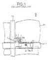
- FIGS. 1 and 2depict an LCD of the conventional art.
- a lower substrate 1 of the LCDincludes a TFT T arranged at an intersection between a data line 13 and a gate line 11 , a pixel electrode 23 connected to a drain electrode 7 of the TFT, and a storage capacitor S positioned at an overlapping portion between the pixel electrode 23 and the pre-stage gate line 11 .
- the TFT Tincludes a gate electrode 3 connected to the gate line 11 , a source electrode 5 connected to the data line 13 , and a drain electrode 7 connected, via a drain contact hole 19 a , to the pixel electrode 23 . Further, the TFT T includes semiconductor layers 15 and 17 for defining a channel between the source electrode 5 and the drain electrode 7 by a gate voltage applied to the gate electrode 3 . Such a TFT T responds to a gate signal from the gate line 11 to selectively apply a data signal from the data line 13 to the pixel electrode 23 .
- the pixel electrode 23is positioned at a cell area divided by the data line 13 and the gate line 11 and is made from a transparent conductive material having a high light transmittance.
- the pixel electrode 23generates a potential difference from a common transparent electrode (not shown) provided at an upper substrate (not shown) by a data signal applied via the drain contact hole 19 a .
- a liquid crystal positioned between the lower substrate 1 and the upper substrate (not shown)is rotated due to its dielectric anisotropy.
- the liquid crystalallows a light applied, via the pixel electrode 23 , from a light source to be transmitted into the upper substrate.
- the storage capacitor Scharges a voltage in an application period of a gate high voltage to the pre-stage gate line 11 while discharging the charged voltage in an application period of a data signal to the pixel electrode 23 . This prevents a voltage variation in the pixel electrode 23 .
- the storage capacitor Sincludes a gate line 11 and a storage electrode 25 .
- the storage electrode 25overlaps the gate line 11 , and a gate insulating film 9 is positioned between the storage electrode 25 and the gate line 11 .
- the storage capacitorsis electrically connected to the pixel electrode 23 via a storage contact hole 19 b defined by a protective film 21 .
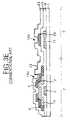
- FIGS. 3A–3EThe conventional method is depicted in FIGS. 3A–3E .
- a gate metal layeris deposited onto the lower substrate 1 and patterned to form the gate line 11 and the gate electrode 3 , as shown in FIG. 3A .
- An insulating materialis entirely deposited onto the lower substrate 1 in such a manner to cover the gate line 11 and the gate electrode 3 .
- the insulating materialforms the gate insulating film 9 shown in FIG. 3B .
- First and second semiconductor materialsare sequentially deposited onto the gate insulating film 9 and then patterned to form an active layer 15 and an ohmic contact layer 17 .
- a data metal layeris deposited onto the gate insulating film 9 and patterned to form the storage electrode 25 , the source electrode 5 and the drain electrode 7 .
- a protective film 21is formed on the gate insulating film 9 , The protective film 21 is then patterned to define the drain contact hole 19 a and the storage contact hole 19 b in such a manner to expose the drain electrode 7 and the storage electrode 25 .
- a transparent conductive materialis deposited onto the protective film 21 and patterned to form the pixel electrode 23 such that the pixel electrode electrically contacts the drain electrode 7 and the storage electrode 25 .
- the source electrode 5 and the drain electrode 7 provided on the lower substrate 1 of such a LCD deviceare formed from a data metal layer such as chrome (Cr) or molybdenum (Mo) in a single layer structure.
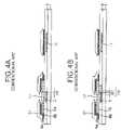
- FIGS. 4A–4Bdepict another conventional LCD device which trends towards a relatively higher resolution than the conventional LCD device of FIGS. 1 and 2 .
- the data metal layerhas a double layer structure of first and second metal layers 6 a and 6 b .
- the first metal layer 6 ais made from a metal such as molybdenum (Mo) or titanium (Ti) while the second metal layer 6 b is made from a material such as aluminum (Al) or an aluminum alloy.
- the data metal layer having the double layer structureWhen the data metal layer having the double layer structure is patterned by the wet etching, it may be over-etched by a certain area D 1 in comparison to a photo resist pattern 27 . When this occurs, if the ohmic contact layer 17 at a portion corresponding to the gate electrode 3 is patterned by the wet etching with the aid of the photo resist pattern 27 , the active layer 15 is exposed as shown in FIG. 4B . This creates a parasitic capacitance Cgd between the gate metal layer, and the data metal layer has a deviation equal to about D 2 due to the over-etched data metal layer, which results in increased difficulty in obtaining uniform picture quality.
- a liquid crystal display deviceincludes a gate electrode provided on a substrate; a gate insulating film provided on the substrate; a semiconductor layer provided on the gate insulating film; a buffer metal layer formed in the same pattern as the semiconductor layer; and source and drain electrodes formed from a data metal layer on the buffer metal layer and the gate insulating film.
- the liquid crystal display devicefurther includes a protective layer provided on the gate insulating film; and a pixel electrode provided on the protective layer.
- the semiconductor layerincludes an active layer provided on the gate insulating film; and an ohmic contact layer provided on the active layer with having a desired distance of holes therebetween.
- the buffer metal layeris formed in the same pattern as the ohmic contact layer.
- the buffer metal layeris made from any one of molybdenum (Mo) and titanium (Ti).
- the data metal layeris made from any one of aluminum (Al), an Al alloy, copper (Cu) and a Cu alloy.
- the data metal layeris patterned by a wet etching.
- the buffer metal layer and the ohmic contact layerare patterned by a dry etching.
- a method of fabricating a liquid crystal display deviceincludes the steps of forming a gate electrode on a substrate; forming a gate insulating film on the substrate; forming a semiconductor layer and a buffer metal layer on the gate insulating film in the same pattern; and forming source and drain electrodes from a data metal layer on the gate insulating film.
- the methodfurther includes the steps of forming a protective layer on the gate insulating film; and forming a pixel electrode on the protective layer.
- the semiconductor layer and the buffer metal layerare patterned by a dry etching.
- the source and drain electrodesare patterned by a wet etching.
- the buffer metal layeris made from any one of molybdenum (Mo) and titanium (Ti).
- the data metal layeris made from any one of aluminum (Al), an Al alloy, copper (Cu) and a Cu alloy.
- a method of fabricating a liquid crystal display deviceincludes the steps of forming a gate electrode on a substrate; forming a gate insulating film on the substrate; forming a semiconductor layer on the gate insulating film; and forming source and drain electrodes by depositing first and second metal layers on the gate insulating film and then patterning the second metal layer by a wet etching and patterning the semiconductor layer and an ohmic contact layer of the semiconductor layer by a dry etching.
- the methodfurther includes the steps of forming a protective layer on the gate insulating film; and forming a pixel electrode on the protective layer.
- the first metal layeris made from any one of molybdenun (Mo) and titanium (Ti).
- the second metal layeris made from any one of aluminum (Al), an Al alloy, copper (Cu) and a Cu alloy.
- FIG. 1is a plan view depicting a structure of a lower substrate of a conventional LCD device
- FIG. 2is a section view depicting the lower substrate of the LCD device of FIG. 1 taken along the A—A line;
- FIGS. 3A to 3Eare section views depicting a conventional process of fabricating the lower substrate of the conventional LCD of FIG. 2 ;
- FIGS. 4A and 4Bare section views depicting a process of forming the source and drain electrodes of a second conventional LCD device according to a second conventional method
- FIG. 5is a section view depicting a structure of a lower substrate of a LCD device according to a first embodiment of the present invention
- FIGS. 6A to 6Edepict section views of one embodiment of a method of fabricating the lower substrate of the LCD of FIG. 5 ;
- FIG. 7is a section view depicting a structure of a lower substrate of a LCD device according to a second embodiment of the present invention.
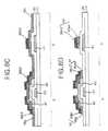
- FIGS. 8A to 8Fare section views depicting a second embodiment of a method of fabricating the lower substrate of the LCD of FIG. 7 .
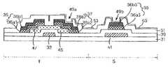
- FIG. 5is a section view showing a structure of a lower substrate 31 of a LCD according to a first embodiment of the present invention.
- the thin film transistor part of substrate 31includes a gate electrode 33 , an active layer 45 , an ohmic contact layer 47 and a gate insulating film 39 between the gate electrode 33 and the ohmic contact layer 47 .
- Source and drain electrodes 35 and 37are above the ohmic contact layer 47 .
- the source and drain electrodes 35 and 37each include a data metal layer 36 b 1 and 36 b 2 formed separately on each buffer metal layer 36 a 1 and 36 a 2 .
- the buffer metal layers 36 a 1 and 36 a 2are formed in the same pattern as the ohmic contact layer 47 .
- the data metal layers 36 b 1 and 36 b 2are formed on each buffer metal layers 36 a 1 and 36 a 2 and the gate insulating film 39 .
- the buffer metal layers 36 a 1 and 36 a 2may be made from Mo or Ti, etc. while the data metal layers 36 b 1 and 36 b 2 may be made from Al, an Al alloy, copper (Cu) or a Cu alloy, etc.
- a protective layer 51is provided.
- a pixel electrode 53is formed on the protective layer 51 .
- the pixel electrode 53is in contact with the drain electrode 37 via a drain contact hole 49 a , which passes through the protective layer 51 .
- the pixel electrode 53During operation of the LCD device, the pixel electrode 53 generates a potential difference from a common electrode (not shown) provided at an upper substrate (not shown) by a data signal applied via the drain contact hole 49 a .
- a liquid crystal positioned between the lower substrate 31 and the upper substrate (not shown)is rotated due to its dielectric anisotropy.
- the liquid crystalallows a light applied from a light source to be transmitted into the upper substrate.
- the storage capacitor part of the LCD deviceincludes a gate line 41 , and a storage electrode 55 above the gate line 41 , and a gate insulating film 39 therebetween.
- the storage electrode 55may be formed from the same material as data metal layer 36 b .
- the storage electrode 55is electrically connected to the pixel electrode 53 , via a storage contact hole 49 b passing through the protective film 51 .
- the storage capacitor partcharges a voltage in an application period of a gate high voltage to the gate line 41 (pre-stage) while discharging the charged voltage in an application period of a data signal to the pixel electrode 53 .
- This method of operationprevents a voltage variation in the pixel electrode 53 .
- FIGS. 6A to 6Edepict one embodiment of a method of fabricating the lower substrate 31 of the LCD device in FIG. 5 .
- the gate line 41 and the gate electrode 33are positioned on the lower substrate 31 .
- the gate line 41 and the gate electrode 33are formed by depositing a material such as aluminum (Al) or copper (Cu) onto the lower substrate 31 by a deposition technique such as a sputtering, etc. and patterning the material.
- the active layer 45 , the ohmic contact layer 47 and the buffer metal layer 36 aare provided on the gate insulating film 39 .
- the gate insulating film 39is formed by depositing an insulating material entirely over the lower substrate 31 using, for example, the plasma enhanced chemical vapor deposition (PECVD) Technique in such a manner to cover the gate line 41 and the gate electrode 33 .
- PECVDplasma enhanced chemical vapor deposition
- the active layer 45 , the ohmic contact layer 47 and the buffer metal layer 36 aare formed by sequentially depositing first and second semiconductor materials and a buffer metal material onto the gate insulating film 39 , and patterning the materials simultaneously in the same pattern.
- the gate insulating film 39is made from an insulating material such as silicon nitride (SiN x ) or silicon oxide (SiO x ).
- the active layer 45is formed from a first semiconductor layer of amorphous silicon, which is not doped with an impurity.
- the ohmic contact layer 47is formed from a second semiconductor layer of amorphous silicon doped with an n-type or p-type impurity.
- the buffer metal layer 36 ais formed from a buffer metal such as Mo or Ti, etc.
- the storage electrode 55 and the data metal layer 36 b 1 of the source electrode 35 and the data metal layer 36 b 2 of the drain electrode 37are provided on the gate insulating film 39 .
- the storage electrode 55 , the data metal layer 36 b 1 of the source electrode 35 and the data metal layer 36 b 2 of the drain electrode 37are formed by depositing a metal layer entirely over the structure of FIG. 6B using the chemical vapor deposition technique or sputtering technique.
- the separation region 50 the data metal layers 36 b 1 and 36 b 2 of the source and drain electrodes 35 and 37are formed by the patterning using a wet etch. The patterning is performed so that the separation region is above the gate electrode 33 .
- the buffer metal layer 36 a and the ohmic contact layer 47 at a portion corresponding to the gate electrode 33are patterned by dry etching to expose the active layer 45 .
- the dry etchis performed using the wet etched data metal layers 36 b 1 and 36 b 2 as a mask.
- the exposed portion of the active layer 45 corresponding to the gate electrode 33 and between the source and drain electrodes 35 and 37defines a channel.
- the storage electrode 55 and the data metal layer 36 bmay be formed from a data metal layer of Al, an Al alloy, Cu or a Cu alloy, etc.
- the protective layer 51is provided on the gate insulating layer 39 , source and drain electrodes 35 and 37 , the storage electrode 55 and channel.
- the protective layer 51is formed by depositing an insulating material onto the structure of FIG. 6C and patterning the insulating material in such a manner to cover the storage electrode 55 , the source electrode 35 and the drain electrode 37 .
- the drain contact hole 49 a and the storage contact hole 49 bare formed in the protective layer 51 to partially expose the surfaces of the drain electrode 37 and the storage electrode 55 .
- the protective layer 51includes an inorganic insulating material such as silicon nitride (SiN x ) or silicon oxide (SiO x ), or an organic insulating material such as an acrylic organic compound, BCB (benzocyclobutene), fluoro resin or PFCB (perfluorocyclobutane).
- an inorganic insulating materialsuch as silicon nitride (SiN x ) or silicon oxide (SiO x )
- an organic insulating materialsuch as an acrylic organic compound, BCB (benzocyclobutene), fluoro resin or PFCB (perfluorocyclobutane).
- a pixel electrode 53is provided on the protective layer 51 .
- the pixel electrode 53is formed by depositing a transparent conductive material onto the protective layer 51 and patterning the material.
- the pixel electrode 53is formed so that it is in electrical contact with the drain electrode 37 through the drain contact hole 49 a while being in electrical contact with the storage electrode 55 through the storage contact hole 49 b .
- the pixel electrode 53is formed from a transparent conductive material such as indium-tin-oxide (ITO), indium-zinc-oxide (IZO) or indium-tin-zinc-oxide (ITZO).
- the source and drain electrodes 35 and 37are formed by patterning the data metal layer 36 b using wet etching. Then, the channel is formed using the metal layer pattern as a mask to dry etch the buffer metal layer 36 a and the ohmic contact layer 47 at a portion corresponding to the gate electrode 33 . Accordingly, an over-etching of the source and drain electrodes 35 and 37 caused by a patterning work of the conventional wet etching is prevented. This can eliminate a phase deviation of a parasitic capacitance Cgd between the drain terminal and the gate terminal.
- the data metal layer 36 b 1 of the source 35 and the data metal layer 36 b 2 of the drain electrodes 37may be patterned by the wet etching, and thereafter, the buffer metal layer 36 a and the ohmic contact layer 47 may be patterned using the photoresist used to pattern the data metal layer 36 b as a mask for the dry etching.
- FIG. 7is a section view showing a structure of a lower substrate of a liquid crystal display according to a second embodiment of the present invention.
- the LCD device depicted in FIG. 7has similar elements as the LCD device shown in FIG. 5 except for the inclusion of the double-layered storage electrode 55 and the structural differences in both metal layers 36 a 2 and 36 b 2 and pixel electrode 53 in contact hole 49 a .
- the data metal layer 36 b and buffered metal layer 36 aare patterned the same.
- the end portions a and b of layers 36 a and 36 b which abut the channel regionare the same length.
- both layers 36 a and 36 bextend wider than the active layer 45 .
- the pixel electrode 53in pixel electrode FIG. 7 , the pixel electrode 53 lines the entire contact hole 49 a.
- FIGS. 8A to FIG. 8Fdepict one embodiment of a method of fabricating the lower substrate 31 of the LCD device in FIG. 7 .
- the gate line 41 and the gate electrode 33are provided on the lower substrate 31 .
- the gate line 41 and the gate electrode 33may be formed by depositing a material such as aluminum (Al) or copper (Cu) onto the lower substrate 31 by a deposition technique such as a sputtering, etc. and patterning the material.
- the gate insulating film 39is formed by depositing an insulating material entirely over the lower substrate 31 using a technique such as plasma enhanced chemical vapor deposition (PECVD) in such a manner to cover the gate line 41 and the gate electrode 33 .
- PECVDplasma enhanced chemical vapor deposition
- the gate insulating film 39may be made from an insulating material such as silicon nitride (SiN x ) or silicon oxide (SiO x ).
- the active layer 45 and the ohmic contact layer 47are formed by depositing first and second semiconductor layers onto the gate insulating film 39 and patterning the layers.
- the active layer 45is formed from a first semiconductor layer of amorphous silicon without being doped with an impurity.
- the ohmic contact layer 47is formed from a second semiconductor layer of amorphous silicon doped with an n-type or p-type impurity.
- the buffer metal layers 36 a 1 to 36 a 3 and the data metal layers 36 b 1 to 36 b 3are provided on the gate insulating film 39 and ohmic contact layer 47 .
- the buffer metal layers 36 a 1 to 36 a 3are formed by depositing a buffer metal over the entire gate insulating film 39 and ohmic contact layer 47 .
- the data metal layers 36 b 1 to 36 b 3are formed by depositing a data metal entirely over the buffer metal layers 36 a 1 to 36 a 3 and then patterning the data metal layer 36 b .
- the buffer metal layers 36 a 1 to 36 a 3may be formed from a buffer metal such as Mo or Ti, etc.
- the data metal layers 36 b 1 to 36 b 3may be formed from a data metal such as Al, an Al alloy, Cu or a Cu alloy.
- the storage electrode 55 , the source electrode 35 and the drain electrode 37are formed on the gate insulating film 39 .
- the storage electrode 55 , the source electrode 35 and the drain electrode 37are formed from the data metal layer 36 b 1 to 36 b 3 and the buffer metal layer 36 a 1 to 36 a 3 patterned by dry etching utilizing the wet etched data metal layer 36 b as a mask.
- the data metal layers 36 b 1 to 36 b 3 and the buffer metal layers 36 a 1 to 36 a 3are formed in the same pattern.
- the ohmic contact layer 47 at a portion above and corresponding to the gate electrode 33is also patterned by the dry etching to expose the active layer 45 .
- the patterning of the portion of the ohmic contact layer 45makes a channel between the source and drain electrodes 35 and 37 .
- a protective layer 51is formed by depositing an insulating material onto the source electrode 35 , drain electrode 37 , storage electrode 55 and gate insulating layer 39 .
- the insulating materialis then patterned in such a manner to cover the storage electrode 55 , the source electrode 35 and the drain electrode 37 .
- the patterning the drain contact hole 49 a and the storage contact hole 49 bso as to pass through the protective layer 51 and partially expose the surfaces of the drain electrode 37 and the storage electrode 55 .
- the protective layer 51is made from an inorganic insulating material such as silicon nitride (SiN x ) or silicon oxide (SiO x ), or an organic insulating material such as an acrylic organic compound, BCB (benzocyclobutene), flucro resin or PFCB (perfluorocyclobutane).
- an inorganic insulating materialsuch as silicon nitride (SiN x ) or silicon oxide (SiO x )
- an organic insulating materialsuch as an acrylic organic compound, BCB (benzocyclobutene), flucro resin or PFCB (perfluorocyclobutane).
- the pixel electrode 53is provided on the protective layer 51 in contact holes 49 a and 49 b .
- the pixel electrode 53is in electrical contact with the drain electrode 37 through the drain contact hole 49 a while being in electrical contact with the storage electrode 55 through the storage contact hole 49 b.
- the pixel electrode 53is formed by depositing a transparent conductive material onto the protective layer 51 and then patterning the material.
- a conductive materialsuch as indium-tin-oxide (ITO), indium-zinc-oxide (IZO) or indium-tin-zinc-oxide (ITZO) is used for the pixel electrode.
- the source and drain electrodes 35 and 37are formed from the buffer metal layer 36 a and the data metal layer 36 b .
- the source and drain electrodes 35 and 37are formed by patterning the data metal layer 36 b 1 and 36 b 2 by the wet etching and then patterning the buffer metal layer 36 a 1 and 36 a 2 and the ohmic contact layer 47 by the dry etching using the data metal layer 36 b 1 and 36 b 2 as a mask.
- the buffer metal layer 36 a 1 and 36 a 2are formed in the same pattern as the data metal layer 36 b 1 and 36 b 2 , and the ohmic contact layer 47 at a portion corresponding to the gate electrode 33 also is patterned by the dry etching to expose the active layer 45 . Accordingly, an over-etching of the source and drain electrodes 35 and 37 caused by patterning work using only the conventional wet etching can be prevented. This can eliminate a phase deviation of a parasitic capacitance Cgd between the drain terminal and the gate terminal. Thus, the parasitic capacitance of the TFT has an uniform distribution, and flicker and a crosstalk can be reduced to obtain a uniform picture quality.
Landscapes
- Physics & Mathematics (AREA)
- Nonlinear Science (AREA)
- Engineering & Computer Science (AREA)
- Microelectronics & Electronic Packaging (AREA)
- Mathematical Physics (AREA)
- Chemical & Material Sciences (AREA)
- Crystallography & Structural Chemistry (AREA)
- General Physics & Mathematics (AREA)
- Optics & Photonics (AREA)
- Thin Film Transistor (AREA)
- Liquid Crystal (AREA)
- Electrodes Of Semiconductors (AREA)
Abstract
Description
Claims (12)
Priority Applications (1)
| Application Number | Priority Date | Filing Date | Title |
|---|---|---|---|
| US11/648,831US7863120B2 (en) | 2001-03-21 | 2007-01-03 | Liquid crystal display device with double metal layer source and drain electrodes and fabricating method thereof |
Applications Claiming Priority (2)
| Application Number | Priority Date | Filing Date | Title |
|---|---|---|---|
| KRP2001-14651 | 2001-03-21 | ||
| KR1020010014651AKR100799464B1 (en) | 2001-03-21 | 2001-03-21 | LCD and its manufacturing method |
Related Child Applications (1)
| Application Number | Title | Priority Date | Filing Date |
|---|---|---|---|
| US11/648,831DivisionUS7863120B2 (en) | 2001-03-21 | 2007-01-03 | Liquid crystal display device with double metal layer source and drain electrodes and fabricating method thereof |
Publications (2)
| Publication Number | Publication Date |
|---|---|
| US20020135710A1 US20020135710A1 (en) | 2002-09-26 |
| US7170571B2true US7170571B2 (en) | 2007-01-30 |
Family
ID=19707201
Family Applications (2)
| Application Number | Title | Priority Date | Filing Date |
|---|---|---|---|
| US10/028,768Expired - LifetimeUS7170571B2 (en) | 2001-03-21 | 2001-12-28 | Liquid crystal display device with double metal layer source and drain electrodes and fabricating method thereof |
| US11/648,831Expired - Fee RelatedUS7863120B2 (en) | 2001-03-21 | 2007-01-03 | Liquid crystal display device with double metal layer source and drain electrodes and fabricating method thereof |
Family Applications After (1)
| Application Number | Title | Priority Date | Filing Date |
|---|---|---|---|
| US11/648,831Expired - Fee RelatedUS7863120B2 (en) | 2001-03-21 | 2007-01-03 | Liquid crystal display device with double metal layer source and drain electrodes and fabricating method thereof |
Country Status (4)
| Country | Link |
|---|---|
| US (2) | US7170571B2 (en) |
| JP (1) | JP4499337B2 (en) |
| KR (1) | KR100799464B1 (en) |
| CN (1) | CN100501540C (en) |
Cited By (3)
| Publication number | Priority date | Publication date | Assignee | Title |
|---|---|---|---|---|
| US20070012916A1 (en)* | 2005-07-14 | 2007-01-18 | Samsung Electronics Co., Ltd. | Flat panel display and method for fabricating the same |
| US20070051955A1 (en)* | 2002-12-31 | 2007-03-08 | Yoo Soon S | Thin film transistor array substrate and manufacturing method of the same |
| US20100084643A1 (en)* | 2008-10-03 | 2010-04-08 | Sony Corporation | Thin film transistor, method for manufacturing thin film transistor, and electronic apparatus |
Families Citing this family (24)
| Publication number | Priority date | Publication date | Assignee | Title |
|---|---|---|---|---|
| KR100866976B1 (en)* | 2002-09-03 | 2008-11-05 | 엘지디스플레이 주식회사 | Array substrate for LCD and manufacturing method |
| KR100652214B1 (en)* | 2003-04-03 | 2006-11-30 | 엘지.필립스 엘시디 주식회사 | Manufacturing method of liquid crystal display device |
| KR100670379B1 (en)* | 2005-12-15 | 2007-01-16 | 삼성에스디아이 주식회사 | Organic thin film transistor, manufacturing method thereof and organic light emitting display device having same |
| JP5250944B2 (en)* | 2006-04-28 | 2013-07-31 | 凸版印刷株式会社 | Structure, transmissive liquid crystal display device, semiconductor circuit manufacturing method, and transmissive liquid crystal display device manufacturing method |
| KR101284697B1 (en)* | 2006-06-30 | 2013-07-23 | 엘지디스플레이 주식회사 | An array substrate for LCD and method for fabricating thereof |
| KR101257811B1 (en)* | 2006-06-30 | 2013-04-29 | 엘지디스플레이 주식회사 | An array substrate for LCD and method for fabricating thereof |
| KR20080008562A (en)* | 2006-07-20 | 2008-01-24 | 삼성전자주식회사 | Manufacturing Method of Array Substrate, Array Substrate and Display Device Having Same |
| KR100937173B1 (en)* | 2006-12-26 | 2010-01-15 | 엘지디스플레이 주식회사 | Array substrate for thin film transistor liquid crystal display device and manufacturing method thereof |
| KR101373735B1 (en) | 2007-02-22 | 2014-03-14 | 삼성디스플레이 주식회사 | Method for manufacturing a aisnal line, thin film transistor array panel and method for manufacturing the same |
| JP5121299B2 (en)* | 2007-05-09 | 2013-01-16 | アルティアム サービシズ リミテッド エルエルシー | Liquid crystal display |
| US7782413B2 (en) | 2007-05-09 | 2010-08-24 | Tohoku University | Liquid crystal display device and manufacturing method therefor |
| KR100920483B1 (en)* | 2007-07-20 | 2009-10-08 | 엘지디스플레이 주식회사 | Array substrate for liquid crystal display device and manufacturing method thereof |
| KR101682078B1 (en)* | 2010-07-30 | 2016-12-05 | 삼성디스플레이 주식회사 | Manufacturing method of thin film transistor array panel |
| US9087749B2 (en) | 2010-12-27 | 2015-07-21 | Sharp Kabushiki Kaisha | Active matrix substrate, and display panel |
| TWI416498B (en) | 2010-12-30 | 2013-11-21 | Au Optronics Corp | Liquid crystal display and driving method thereof |
| US9070600B2 (en)* | 2011-02-07 | 2015-06-30 | Sharp Kabushiki Kaisha | Active matrix substrate, display panel, and display device |
| US9040416B2 (en)* | 2013-05-10 | 2015-05-26 | Samsung Display Co., Ltd. | Manufacturing method of metal wire and thin transistor array panel |
| KR102130139B1 (en)* | 2013-07-30 | 2020-07-03 | 엘지디스플레이 주식회사 | Organic Light Emitting Diode Display Having Thin Film Transistor Substrate Using Oxide Semiconductor And Method For Manufacturing The Same |
| KR102248645B1 (en)* | 2013-12-02 | 2021-05-04 | 엘지디스플레이 주식회사 | Thin Film Transistor Substrate Having Metal Oxide Semiconductor and Manufacturing Method Thereof |
| TWI572020B (en) | 2016-01-19 | 2017-02-21 | 友達光電股份有限公司 | Array substrate and manufacturing method thereof |
| US10446632B2 (en) | 2017-12-28 | 2019-10-15 | Wuhan China Star Optoelectronics Semiconductor Display Technology Co., Ltd. | Organic light-emitting diode display panel |
| CN108183125B (en)* | 2017-12-28 | 2020-12-29 | 武汉华星光电半导体显示技术有限公司 | Organic Light Emitting Diode Display Panel |
| CN108231674A (en)* | 2018-02-05 | 2018-06-29 | 深圳市华星光电半导体显示技术有限公司 | Thin-film transistor array base-plate and its manufacturing method |
| US10553614B2 (en) | 2018-02-05 | 2020-02-04 | Shenzhen China Star Optoelectronics Semiconductor Display Technology Co., Ltd. | Thin-film transistor array substrate and manufacturing method for the same |
Citations (6)
| Publication number | Priority date | Publication date | Assignee | Title |
|---|---|---|---|---|
| US6078365A (en)* | 1996-01-25 | 2000-06-20 | Kabushiki Kaisha Toshiba | Active matrix liquid crystal panel having an active layer and an intervening layer formed of a common semiconductor film |
| CN1257304A (en) | 1998-12-12 | 2000-06-21 | 三星电子株式会社 | Thin film transistor array panel for liquid crystal display and making method thereof |
| JP2000349294A (en) | 1999-06-03 | 2000-12-15 | Matsushita Electric Ind Co Ltd | Method for manufacturing thin film transistor |
| US20020135709A1 (en)* | 2001-03-21 | 2002-09-26 | Gee Sung Chae | Liquid crystal display device and fabricating method thereof |
| US6493048B1 (en)* | 1998-10-21 | 2002-12-10 | Samsung Electronics Co., Ltd. | Thin film transistor array panel for a liquid crystal display and a method for manufacturing the same |
| US20030085404A1 (en)* | 1999-04-26 | 2003-05-08 | Dong-Gyu Kim | Thin film transistor array panel and a method for manufacturing the same |
Family Cites Families (16)
| Publication number | Priority date | Publication date | Assignee | Title |
|---|---|---|---|---|
| US5198694A (en)* | 1990-10-05 | 1993-03-30 | General Electric Company | Thin film transistor structure with improved source/drain contacts |
| JP3316566B2 (en) | 1993-12-17 | 2002-08-19 | 財団法人石油産業活性化センター | Reduction and purification method of exhaust gas containing nitrogen oxides |
| JPH07191347A (en)* | 1993-12-27 | 1995-07-28 | Casio Comput Co Ltd | Method of manufacturing thin film transistor array |
| JP3281167B2 (en)* | 1994-03-17 | 2002-05-13 | 富士通株式会社 | Method for manufacturing thin film transistor |
| US5621556A (en) | 1994-04-28 | 1997-04-15 | Xerox Corporation | Method of manufacturing active matrix LCD using five masks |
| US5539219A (en)* | 1995-05-19 | 1996-07-23 | Ois Optical Imaging Systems, Inc. | Thin film transistor with reduced channel length for liquid crystal displays |
| US5668032A (en)* | 1995-07-31 | 1997-09-16 | Holmberg; Scott H. | Active matrix ESD protection and testing scheme |
| US5731216A (en)* | 1996-03-27 | 1998-03-24 | Image Quest Technologies, Inc. | Method of making an active matrix display incorporating an improved TFT |
| JPH1022508A (en)* | 1996-07-04 | 1998-01-23 | Sharp Corp | Method for manufacturing thin film transistor |
| JPH1027910A (en)* | 1996-07-11 | 1998-01-27 | Hitachi Ltd | Manufacturing method of TFT substrate |
| KR100272537B1 (en)* | 1997-10-09 | 2000-11-15 | 구본준 | An in plane switching mode liquid crystal display device |
| KR100486719B1 (en)* | 1998-12-12 | 2005-08-17 | 엘지.필립스 엘시디 주식회사 | LCD and its manufacturing method |
| JP3916334B2 (en) | 1999-01-13 | 2007-05-16 | シャープ株式会社 | Thin film transistor |
| JP3362008B2 (en)* | 1999-02-23 | 2003-01-07 | シャープ株式会社 | Liquid crystal display device and manufacturing method thereof |
| JP2000307118A (en)* | 1999-04-21 | 2000-11-02 | Matsushita Electric Ind Co Ltd | Thin film transistor and method of manufacturing the same |
| KR20000072230A (en)* | 2000-08-19 | 2000-12-05 | 장진 | fabrication method of amorphous silicon thin-film transistor for liquid-crystal display |
- 2001
- 2001-03-21KRKR1020010014651Apatent/KR100799464B1/ennot_activeExpired - Lifetime
- 2001-12-28USUS10/028,768patent/US7170571B2/ennot_activeExpired - Lifetime
- 2002
- 2002-03-18CNCNB021075727Apatent/CN100501540C/ennot_activeExpired - Fee Related
- 2002-03-20JPJP2002079429Apatent/JP4499337B2/ennot_activeExpired - Fee Related
- 2007
- 2007-01-03USUS11/648,831patent/US7863120B2/ennot_activeExpired - Fee Related
Patent Citations (7)
| Publication number | Priority date | Publication date | Assignee | Title |
|---|---|---|---|---|
| US6078365A (en)* | 1996-01-25 | 2000-06-20 | Kabushiki Kaisha Toshiba | Active matrix liquid crystal panel having an active layer and an intervening layer formed of a common semiconductor film |
| US6493048B1 (en)* | 1998-10-21 | 2002-12-10 | Samsung Electronics Co., Ltd. | Thin film transistor array panel for a liquid crystal display and a method for manufacturing the same |
| CN1257304A (en) | 1998-12-12 | 2000-06-21 | 三星电子株式会社 | Thin film transistor array panel for liquid crystal display and making method thereof |
| US6531392B2 (en)* | 1998-12-12 | 2003-03-11 | Samsung Electronics Co., Ltd. | Method of forming a thin film transistor array panel using photolithography techniques |
| US20030085404A1 (en)* | 1999-04-26 | 2003-05-08 | Dong-Gyu Kim | Thin film transistor array panel and a method for manufacturing the same |
| JP2000349294A (en) | 1999-06-03 | 2000-12-15 | Matsushita Electric Ind Co Ltd | Method for manufacturing thin film transistor |
| US20020135709A1 (en)* | 2001-03-21 | 2002-09-26 | Gee Sung Chae | Liquid crystal display device and fabricating method thereof |
Cited By (6)
| Publication number | Priority date | Publication date | Assignee | Title |
|---|---|---|---|---|
| US20070051955A1 (en)* | 2002-12-31 | 2007-03-08 | Yoo Soon S | Thin film transistor array substrate and manufacturing method of the same |
| US7411217B2 (en)* | 2002-12-31 | 2008-08-12 | Lg Display Co., Ltd. | Thin film transistor array substrate and manufacturing method of the same |
| US20070012916A1 (en)* | 2005-07-14 | 2007-01-18 | Samsung Electronics Co., Ltd. | Flat panel display and method for fabricating the same |
| US7575951B2 (en)* | 2005-07-14 | 2009-08-18 | Samsung Electronics Co., Ltd. | Flat panel display and method for fabricating the same |
| US20100084643A1 (en)* | 2008-10-03 | 2010-04-08 | Sony Corporation | Thin film transistor, method for manufacturing thin film transistor, and electronic apparatus |
| US8242501B2 (en)* | 2008-10-03 | 2012-08-14 | Sony Corporation | Thin film transistor and electronic apparatus |
Also Published As
| Publication number | Publication date |
|---|---|
| US20020135710A1 (en) | 2002-09-26 |
| JP4499337B2 (en) | 2010-07-07 |
| KR100799464B1 (en) | 2008-02-01 |
| US20070109458A1 (en) | 2007-05-17 |
| US7863120B2 (en) | 2011-01-04 |
| CN100501540C (en) | 2009-06-17 |
| JP2003005220A (en) | 2003-01-08 |
| KR20020074702A (en) | 2002-10-04 |
| CN1375733A (en) | 2002-10-23 |
Similar Documents
| Publication | Publication Date | Title |
|---|---|---|
| US7863120B2 (en) | Liquid crystal display device with double metal layer source and drain electrodes and fabricating method thereof | |
| US7522224B2 (en) | Array substrate of liquid crystal display and fabricating method thereof | |
| US7413938B2 (en) | Thin film transistor array substrate and method of manufacturing the same | |
| US20060290864A1 (en) | Horizontal electric field switching liquid crystal display device and fabricating method thereof | |
| US6888586B2 (en) | Array substrate for liquid crystal display and method for fabricating the same | |
| US8497949B2 (en) | Liquid crystal display device and fabricating method thereof | |
| KR20030082651A (en) | Thin film transistor array substrate and method of manufacturing the same | |
| KR100886241B1 (en) | Manufacturing method of liquid crystal display device | |
| US7492418B2 (en) | Liquid crystal display device with particular metal layer configuration of TFT and fabricating method thereof | |
| US6876404B2 (en) | Liquid crystal display device and fabricating method thereof | |
| KR101127836B1 (en) | Method of Fabricating Thin Film Transistor Substrate | |
| US7737446B2 (en) | Thin films transistor array substrate and fabricating method thereof | |
| US6958788B2 (en) | Liquid crystal display device and method of fabricating the same | |
| KR100897487B1 (en) | Array substrate of liquid crystal display device and manufacturing method thereof | |
| KR100443829B1 (en) | Array Substrate of Liquid Crystal Display Device and Fabricating Method Thereof | |
| KR101097675B1 (en) | Thin film transistor and fabricating method thereof | |
| KR100799465B1 (en) | LCD and its manufacturing method | |
| KR100843959B1 (en) | Array substrate for liquid crystal display device and manufacturing method thereof | |
| KR20040061206A (en) | Liquid Crystal Display Panel and Fabricating Method Thereof | |
| KR20040062189A (en) | Device and the fabrication method for lcd |
Legal Events
| Date | Code | Title | Description |
|---|---|---|---|
| AS | Assignment | Owner name:LG PHILLIPS LCD CO., LTD., KOREA, REPUBLIC OF Free format text:ASSIGNMENT OF ASSIGNORS INTEREST;ASSIGNOR:CHAE, GEE SUNG;REEL/FRAME:012419/0237 Effective date:20011226 | |
| AS | Assignment | Owner name:LG PHILIPS LCD CO., LTD., KOREA, REPUBLIC OF Free format text:CORRECTION TO THE ASSIGNEE;ASSIGNOR:CHAE, GEE SUNG;REEL/FRAME:012661/0113 Effective date:20011226 | |
| STCF | Information on status: patent grant | Free format text:PATENTED CASE | |
| AS | Assignment | Owner name:LG DISPLAY CO., LTD., KOREA, REPUBLIC OF Free format text:CHANGE OF NAME;ASSIGNOR:LG.PHILIPS LCD CO., LTD.;REEL/FRAME:020985/0675 Effective date:20080304 Owner name:LG DISPLAY CO., LTD.,KOREA, REPUBLIC OF Free format text:CHANGE OF NAME;ASSIGNOR:LG.PHILIPS LCD CO., LTD.;REEL/FRAME:020985/0675 Effective date:20080304 | |
| FEPP | Fee payment procedure | Free format text:PAYOR NUMBER ASSIGNED (ORIGINAL EVENT CODE: ASPN); ENTITY STATUS OF PATENT OWNER: LARGE ENTITY | |
| FPAY | Fee payment | Year of fee payment:4 | |
| FPAY | Fee payment | Year of fee payment:8 | |
| MAFP | Maintenance fee payment | Free format text:PAYMENT OF MAINTENANCE FEE, 12TH YEAR, LARGE ENTITY (ORIGINAL EVENT CODE: M1553) Year of fee payment:12 |