US7170412B2 - Angle of position object location system and method - Google Patents
Angle of position object location system and methodDownload PDFInfo
- Publication number
- US7170412B2 US7170412B2US10/931,476US93147604AUS7170412B2US 7170412 B2US7170412 B2US 7170412B2US 93147604 AUS93147604 AUS 93147604AUS 7170412 B2US7170412 B2US 7170412B2
- Authority
- US
- United States
- Prior art keywords
- backscatter
- rfid tag
- angle
- rfid
- modulated signals
- Prior art date
- Legal status (The legal status is an assumption and is not a legal conclusion. Google has not performed a legal analysis and makes no representation as to the accuracy of the status listed.)
- Expired - Lifetime, expires
Links
Images


Classifications
- G—PHYSICS
- G01—MEASURING; TESTING
- G01S—RADIO DIRECTION-FINDING; RADIO NAVIGATION; DETERMINING DISTANCE OR VELOCITY BY USE OF RADIO WAVES; LOCATING OR PRESENCE-DETECTING BY USE OF THE REFLECTION OR RERADIATION OF RADIO WAVES; ANALOGOUS ARRANGEMENTS USING OTHER WAVES
- G01S13/00—Systems using the reflection or reradiation of radio waves, e.g. radar systems; Analogous systems using reflection or reradiation of waves whose nature or wavelength is irrelevant or unspecified
- G01S13/74—Systems using reradiation of radio waves, e.g. secondary radar systems; Analogous systems
- G01S13/82—Systems using reradiation of radio waves, e.g. secondary radar systems; Analogous systems wherein continuous-type signals are transmitted
- G01S13/84—Systems using reradiation of radio waves, e.g. secondary radar systems; Analogous systems wherein continuous-type signals are transmitted for distance determination by phase measurement
- G—PHYSICS
- G01—MEASURING; TESTING
- G01S—RADIO DIRECTION-FINDING; RADIO NAVIGATION; DETERMINING DISTANCE OR VELOCITY BY USE OF RADIO WAVES; LOCATING OR PRESENCE-DETECTING BY USE OF THE REFLECTION OR RERADIATION OF RADIO WAVES; ANALOGOUS ARRANGEMENTS USING OTHER WAVES
- G01S13/00—Systems using the reflection or reradiation of radio waves, e.g. radar systems; Analogous systems using reflection or reradiation of waves whose nature or wavelength is irrelevant or unspecified
- G01S13/74—Systems using reradiation of radio waves, e.g. secondary radar systems; Analogous systems
- G01S13/82—Systems using reradiation of radio waves, e.g. secondary radar systems; Analogous systems wherein continuous-type signals are transmitted
- G01S13/825—Systems using reradiation of radio waves, e.g. secondary radar systems; Analogous systems wherein continuous-type signals are transmitted with exchange of information between interrogator and responder
- G—PHYSICS
- G01—MEASURING; TESTING
- G01S—RADIO DIRECTION-FINDING; RADIO NAVIGATION; DETERMINING DISTANCE OR VELOCITY BY USE OF RADIO WAVES; LOCATING OR PRESENCE-DETECTING BY USE OF THE REFLECTION OR RERADIATION OF RADIO WAVES; ANALOGOUS ARRANGEMENTS USING OTHER WAVES
- G01S3/00—Direction-finders for determining the direction from which infrasonic, sonic, ultrasonic, or electromagnetic waves, or particle emission, not having a directional significance, are being received
- G01S3/02—Direction-finders for determining the direction from which infrasonic, sonic, ultrasonic, or electromagnetic waves, or particle emission, not having a directional significance, are being received using radio waves
- G01S3/14—Systems for determining direction or deviation from predetermined direction
- G01S3/28—Systems for determining direction or deviation from predetermined direction using amplitude comparison of signals derived simultaneously from receiving antennas or antenna systems having differently-oriented directivity characteristics
- G01S3/32—Systems for determining direction or deviation from predetermined direction using amplitude comparison of signals derived simultaneously from receiving antennas or antenna systems having differently-oriented directivity characteristics derived from different combinations of signals from separate antennas, e.g. comparing sum with difference
- G—PHYSICS
- G01—MEASURING; TESTING
- G01S—RADIO DIRECTION-FINDING; RADIO NAVIGATION; DETERMINING DISTANCE OR VELOCITY BY USE OF RADIO WAVES; LOCATING OR PRESENCE-DETECTING BY USE OF THE REFLECTION OR RERADIATION OF RADIO WAVES; ANALOGOUS ARRANGEMENTS USING OTHER WAVES
- G01S5/00—Position-fixing by co-ordinating two or more direction or position line determinations; Position-fixing by co-ordinating two or more distance determinations
- G01S5/02—Position-fixing by co-ordinating two or more direction or position line determinations; Position-fixing by co-ordinating two or more distance determinations using radio waves
- G01S5/12—Position-fixing by co-ordinating two or more direction or position line determinations; Position-fixing by co-ordinating two or more distance determinations using radio waves by co-ordinating position lines of different shape, e.g. hyperbolic, circular, elliptical or radial
- G—PHYSICS
- G01—MEASURING; TESTING
- G01V—GEOPHYSICS; GRAVITATIONAL MEASUREMENTS; DETECTING MASSES OR OBJECTS; TAGS
- G01V15/00—Tags attached to, or associated with, an object, in order to enable detection of the object
- G—PHYSICS
- G01—MEASURING; TESTING
- G01S—RADIO DIRECTION-FINDING; RADIO NAVIGATION; DETERMINING DISTANCE OR VELOCITY BY USE OF RADIO WAVES; LOCATING OR PRESENCE-DETECTING BY USE OF THE REFLECTION OR RERADIATION OF RADIO WAVES; ANALOGOUS ARRANGEMENTS USING OTHER WAVES
- G01S5/00—Position-fixing by co-ordinating two or more direction or position line determinations; Position-fixing by co-ordinating two or more distance determinations
- G01S5/02—Position-fixing by co-ordinating two or more direction or position line determinations; Position-fixing by co-ordinating two or more distance determinations using radio waves
- G01S5/04—Position of source determined by a plurality of spaced direction-finders
Definitions
- This inventiongenerally relates to object location systems, and more specifically relates to object location systems and radio frequency identification (RFID).
- RFIDradio frequency identification
- the present inventionprovides an object location system and method for locating objects.
- the systemincludes an RFID reader, an angle calculator, and a distance calculator to determine which of a plurality of zones an object is located in or passing through.
- An RFID tagis affixed with the object that is to be located.
- the RFID readertransmits signals to the RFID tag and receives backscatter-modulated signals from the RFID tag at one or more RFID antennas. From those received signals, the angle calculator determines an angle of position of the RFID tag relative to the RFID antenna. From the angle of position the zone in which the object is located is determined.
- a plurality of RFID antennasare distributed over an area.
- each of the multiple RFID antennasreceives a backscatter-modulated signal from the RFID tag and the angle of position relative to each RFID antenna is determined.
- the multiple angles of position at multiple locationsare then used to triangulate the position of the object that includes the RFID tag.
- the system and methodis able to determine a zone in which the object is located.
- system and methodfurther includes a distance calculator. Again, signals from the RFID tag are received by the RFID reader, and these signals are used to determine the distance to object. The distance measurement is then combined with angle of position measurement to again determine the zone in which the object is located.
- the system and methodis able to determine which of a plurality of zones an object is located in.
- the system and methodcan be implemented to determine which of a plurality of portals an object is in, or passing through.
- each portalis a defined zone and the system and method can use angle of position and/or distance measurements to determine which portal the object has passed through.
- Such a systemhas application in inventory tracking where it is desirable to provide an accurate determination of where a product has been moved to. For example, such a system can be used to confirm that a particular shipment of products have been loaded onto a particular truck through a particular portal.
- the system and methodcan be used to provide efficient object location and tracking.
- FIG. 1is a schematic view of an object location system in accordance with an exemplary embodiment of the present invention
- FIG. 2is a flow diagram of a method for locating an object in accordance with an exemplary embodiment of the present invention
- FIGS. 3 and 4are schematic views of an area with a object location system in accordance with an exemplary embodiment of the present invention.
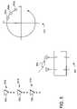
- FIGS. 5 and 6are schematic views of an antenna pair and sum-delta plots in accordance with an exemplary embodiment of the present invention
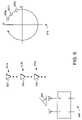
- FIG. 7is a schematic view of two antenna pairs and sum-delta plots is accordance with an exemplary embodiment of the present invention.
- FIG. 8is a flow diagram of distance determination method in accordance with an exemplary embodiment of the present invention.
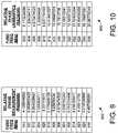
- FIGS. 9 and 10are table views of an exemplary data set in accordance with an exemplary embodiment of the present invention.
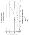
- FIGS. 11 and 12are graph views of an exemplary data set in accordance with an exemplary embodiment of the present invention.
- the present inventionprovides a system and method for locating objects that uses Radio Frequency Identification (RFID) tags for more accurate object location.
- RFIDis a technology that incorporates the use of electromagnetic, electrostatic or magnetic coupling in the radio frequency spectrum to identify objects to which RFID tags are affixed.
- RFID systemsin general provide the advantage of not requiring direct contact or line-of-sight scanning.
- a typical RFID systemincludes an RFID reader and a plurality of RFID tags that are affixed to the objects of interest.
- the RFID readerincludes an antenna and also includes or is coupled to a transceiver.
- the RFID readeruses the antenna and transceiver to transmit and receive radio frequency signals to and from the RFID tag.
- the RFID readerhas the ability to select one or more tags by transmitting an identifier that specifies one or more of the tags from a plurality of tags.
- an RFID readerselects an RFID tag, the RFID tag is put into a responsive mode, with other tags going into a muted state.
- the tagWhen put into responsive mode, the tag transmits data back to the reader by modulating a backscattered signal that is received at the RFID reader antenna.
- some tagsuse variable impedance coupled to the antenna that can be used to change the amount of energy that is reflected back by the tag. These tags can transmit data to the reader by selectively varying the impedance to modulate the backscattered signals. Similarly, these tags can be put into a “muted” or non-responsive state by selecting and maintaining an impedance value.
- an RFID readercan be used to select one or more RFID tags and retrieve data from the selected tags.
- RFID tagscan be used to identify and track large numbers of objects.
- RFID tagshave a relatively low per-unit cost, they have the ability to track large numbers of objects at relatively low costs.
- RFID tagsare used in a variety of commercial contexts that require a unique identification system for large numbers of items. As examples, RFID tags are used in everything from department store inventory and checkout systems to the tracking of military supplies. RFID systems are often preferred for object identification due to their increased range, lack of a line of sight requirement between a tag and its reader, and high multi-tag throughput.
- RFID tagsare available in a variety of configurations, shapes and sizes. For example, different tags for different applications typically have a shape and size appropriate for its application.
- RFID tagsare commonly categorized as active, passive or semi-passive. Active RFID tags include an internal battery used to power the tag and transmit data and typically include the ability to read and write greater amounts of stored data than either passive or semi-passive tags. Passive RFID tags transmit by reflecting and absorbing energy from the RF transmissions from the reader, and use absorbed energy from the reader for data storage, retrieval, and manipulation.
- Semi-passive tagsinclude an internal battery that is used for data storage, retrieval, and manipulation, and transmit data by reflecting and absorbing energy from the reader.
- Passive and semi-passive tagsare typically lighter and less expensive than active tags. Passive tags offer a virtually unlimited operational lifetime because they do not require a battery for operation. The trade off is that they typically have a shorter read range than active tags, and require a higher output power from the reader. It is important to note that governmental restrictions in many jurisdictions restrict reader output power to ensure safety and to minimize interference between devices that must share frequency bands.
- Passive and semi-passive tagsinclude both read-only tags that are programmable once with a unique set of data that cannot be later modified, and read/writeable tags that can be rewritten one or more times using a suitable RFID writing device.
- Another type of RFID tagare multi-mode tags.
- Multi-mode tagscan operate using more than one mode. For example, some multi-mode tags can operate as both passive or semi-passive tags depending on individual needs. Other multi-mode tags can operate as passive, semi-passive or active tags.
- some multi-mode tagscan communicate using a variety of protocols, 802.11x (where 802.11x is defined to include any of the various 802.11 protocols) or Bluetooth specifications.
- RFID systemscan use a variety of techniques to transmit data to and from the tag.
- the datacan be transmitted using any of a variety of modulation techniques, including amplitude modulation (AM), phase modulation (PM), and frequency modulation (FM).
- modulation techniquesincluding amplitude modulation (AM), phase modulation (PM), and frequency modulation (FM).
- FMfrequency modulation
- the data transmitted to the tagcan be encoded using any of a variety of techniques, including frequency shift keying (FSK), pulse position modulation (PPM), pulse duration modulation (PDM), and amplitude shift keying (ASK).
- FSKfrequency shift keying
- PPMpulse position modulation
- PDMpulse duration modulation
- ASKamplitude shift keying
- passive and semi-passive tagstransmit by selectively reflecting and absorbing energy from the reader, in a process generally referred to as backscatter modulation.
- the datacan be encoded using a variety of techniques.
- the datacan be encoded using FSK, where the tag absorb-reflects at one rate to represent a first state (e.g., “one”) and at another rate to represent a second state (e.g., “zero”).
- the datacan be encoded using ASK, where the tag absorb-reflects at one rate for some duration to represent a first state (e.g., “one”) and ceases backscatter modulation for another duration to represent a second state (e.g., “zero”).
- RFID systemsalso typically use a variety of different frequency ranges, including 30 KHz–500 KHz, 850 MHz–950 MHz and 2.4 GHz–2.5 GHz, depending on the regulatory spectrum allocations and performance requirements matched to various application requirements. For example, lower frequency systems typically provide better electromagnetic penetration through water while higher frequency systems do not. Lower frequency passive systems commonly operate within a few inches with small reader antennas while higher frequency systems commonly operate within several feet with similarly sized antennas. Also, lower frequency regulatory allocations are generally more widespread worldwide and typically allow more output power for passive tags than do higher frequency systems. However, where higher frequency spectrum is available for RFID, such as within FCC regulated domains, the output power is substantial and allows for robust long-range performance.
- the present inventionprovides an object location system and method for locating objects.
- FIG. 1an object location system 100 is illustrated schematically.
- the system 100includes an RFID reader 102 , an angle calculator 104 , and a distance calculator 106 to determine which of a plurality of zones an object is located in or passing through.
- An RFID tagis affixed with the object that is to be located.
- the RFID reader 102addresses and transmits signals to the RFID tag and receives backscatter-modulated signals from the RFID tag at one or more RFID antennas. From those received signals, the angle calculator 104 determines an angle of position of the RFID tag relative to the RFID antenna. From the angle of position the zone in which the object is located is determined. In one embodiment, a plurality of RFID antennas are distributed over an area.
- each of the multiple RFID antennasreceives a backscatter-modulated signal from the RFID tag and the angle of position relative to each RFID antenna is determined.
- the multiple angles of position at multiple locationsare then used to triangulate the position of the object that includes the RFID tag.
- the system 100is able to determine the zone in which the object is located.
- the system 100includes a distance calculator 106 . Again, signals from the RFID tag are received by the RFID reader 102 , and these signals are used to determine the distance to the object. The distance measurement is then combined with an angle of position measurement to again determine the zone in which the object is located.
- system 100is able to determine which of a plurality of zones an object is located in.
- the system 100can be implemented to determine which of a plurality of portals an object is in, or passing through.
- each portalis a defined zone and the system 100 uses angle of position and/or distance measurements to determine which portal the object has passed through.
- Such a system 100has application in inventory tracking where it is desirable to provide an accurate determination of where a product has been moved to. For example, such a system can be used to confirm that a particular shipment of products have been loaded onto a particular truck through a particular portal.
- the system 100can be used to provide efficient object location and tracking.
- the system 100can be implemented in variety of ways.
- the angle calculator 104 and distance calculator 106can be fully implemented as part of each RFID reader.
- the angle calculator 104 and distance calculator 106can be implemented at a central location, with the phase and other data used to calculate the angle and distance transmitted to the central computer using any suitable networking technology.
- the angle calculator 104 and distance calculator 106can be implemented partially in the reader, and partially at a central location.
- the first step 202 in method 200is to transmit a plurality of signals from RFID reader(s) to the tag. This will typically include addressing the RFID tag. When an RFID tag is addressed, it is put into a responsive mode where it will modulate and backscatter the received signals from the reader. Other tags within range of the reader that are not addressed will typically go into a muted state, where their reflections are intentionally minimized. Thus, the RFID readers are able to select one out of many different tags and receive backscatter-modulated signals only from the selected RFID tag.
- the transmitted signals from the RFID readerare received by the RFID tag.
- the selected RFID tagbackscatter modulates the plurality of transmitted signals to create a plurality of backscatter-modulated signals.
- the RFID readerreceives the backscatter-modulated signals at one or more antennas and demodulates the plurality of backscatter-modulated signals.
- the next step 206is to determine the angle of position of the RFID tag from the received signals.
- the angle of positioncan be determined by receiving and processing the modulated signals from the RFID tag at an antenna pair. The received modulated signals at each antenna are added and subtracted to create a sum and delta output.
- the angle of position of the RFID tag and its associated objectcan be determined. Specifically, by tracking the sum and delta signals resulting from multiple backscatter-modulated signals as the object moves and determining the resulting rotation direction in sum/delta space, the angle of position of the RFID tag relative to the antenna pair can be roughly determined.
- the next step 208is to determine the zone in which object resides from the angle of positions.
- the angle of positioncan be determined relative to several different RFID antenna pairs.
- the multiple angles of position relative to multiple RFID reader antenna pairscan then be used to triangulate the approximate position of the object that includes the RFID tag.
- the angle of positionis combined with a distance measurement to determine the zone in which the object resides.
- One technique for determining the distance measurementis to use a phase difference of arrival process that will be described in greater detail below.
- the portal area 300is exemplary of the type of area in which the system and method can be adapted to determine the location of objects.
- the area 300includes three portals, 304 a , 304 b and 304 c , through which objects are transported.
- the object location system and methodcan be used to determine which of the portals 304 an object is moving through.
- Such a systemhas many different applications. For example, it has application in inventory systems where it is desirable to verify that a specific object is or has been delivered through a specific portal. Thus, the system can be used to track inventory passing through the portals 304 to ensure that specific inventory reaches its intended destination.
- RFID tagsare attached to the objects and used to determine the location of the object in general, and which portal an object is passing through in specific.
- three objects 306 , 308 and 310are illustrated.
- Each objectwould include one or more RFID tags that are used for object tracking.
- each object 306 , 308 and 310can comprise an individual item, or can include groups of items bundled and/or packaged together.
- the systemincludes an RFID reader with a plurality of antennas 302 a, 302 b, 302 c and 302 d .
- the antennas 302are positioned between and at the edges of the portals, where they can be used to determine which portal an object is moving through.
- Each antenna 302can include one or more antennas, and each antenna 302 would preferably include an antenna pair.
- the RFID readerwill transmit a plurality of signals to the associated RFID tag on the object.
- the RFID tagwill create a plurality backscatter-modulated signals.
- the backscater modulated signalsare received at one or more of the RFID antennas 302 , where they are used to determine which portal the object is moving through.
- the RFID tag on object 306creates backscatter-modulated signals that are received at RFID antennas 302 b and 302 c .
- the angle of position of the object 306is determined, and from this it can be determined that the object 306 is passing through portal 304 b .
- the angle 314 relative antenna 302 b and object 306and also determining the angle 316 relative antenna 302 c and object 306 , it can be determined that the object 306 is between antennas 302 c and 302 b . From this it can be reasonably inferred that the object 306 is passing through portal 304 b.
- angle of position measurementsit may be desirable to combine angle of position measurements with distance measurements to determine object location.
- the backscatter-modulated signals from the RFID tagwill only be received at one RFID antenna.
- the distance measurementcan be combined with the one angle of position measurement to determine object location.
- FIG. 4the portal area 300 is again illustrated.
- object 308is moving through the portal area 300 .
- the RFID readerwill transmit a plurality of signals to the associated RFID tag.
- the RFID tagcreates a plurality of backscatter-modulated signals.
- the backscatter modulated signalsare received at one or more RFID antennas 302 , where they are used to determine which portal the object is moving through.
- the RFID tag on object 308creates backscatter-modulated signals that are received at RFID antenna 302 b .
- the angle of position and distance to the object 308is determined, and from this it can be determined that the object 308 is passing through portal 304 a .
- the object 308is between antennas 302 a and 302 b . From this it can be reasonably inferred that the object 308 is passing through portal 304 a.
- the system and methodis able to use backscatter-modulated signals from RFID tags on objects to determine the angle of position and/or distance to the RFID tag, and from that determine which portal the object is passing through.
- the RFID antenna pair 500is exemplary of the type of antennas that can be used in the system and method for object location.
- the antenna pair 500can be used for each antenna 302 as illustrated in FIGS. 3 and 4 .
- the antenna pair 500includes two antennas (labeled 1 and 2 ), a summation output ( ⁇ ) and a delta output ( ⁇ ).
- the sum output ⁇produces a vector sum of the signals received at the antennas.
- the delta output ⁇produces a vector difference of the signals received at the antennas.
- the sum output ⁇ and delta output ⁇will be used to determine the angle of position. Specifically, by determining the change in the sum and delta outputs that result from the movement of the object, the angle of position of the object can be determined. That is, an object moving on one side of the centerline of the antenna pair will result in clockwise change in the sum and delta output space, while an object moving on the other side of the centerline will result in a counter-clockwise change in the sum and delta output space.
- the antennas in the antenna pair 500are preferably spaced at a spacing of 1 ⁇ 2 wavelength of the carrier frequency.
- This spacingis optimal based on antenna array theory which shows that the effective capture area of a single antenna element has a radius of approximately 1 ⁇ 4 wavelength.
- placing two antenna elements next to each otherresults in the optimal capture area for the antenna pair for the 1 ⁇ 2 wavelength spacing. If the spacing is less than 1 ⁇ 2 wavelength the effective capture area is reduced from optimum. If the antenna spacing is larger that 1 ⁇ 2 wavelength, the antennas create an interferometer and multiple lobes, sometimes called grating lobes, will be created in the antenna pattern resulting in a possible ambiguity in the received signals.
- the illustrated antenna pair 500can be implemented with a 180-degree hybrid.
- a 180 degree hybridis a four-port device with a 180 degree phase shift between two output ports. If a signal is applied to port 1 , this signal will be evenly split and in-phase between ports 2 and 3 with port 4 being isolated. If the signal is applied to port 4 , the signal is divided between ports 2 and 3 with a 180 degree phase shift and port 1 is isolated. When operated as a combiner with signals applied at ports 2 and 3 , the sum of the inputs will be observed at port 1 and the difference will be observed at port 4 . Hence ports 1 and 4 are referred as the sum and delta ports.
- the 180-degree hybridreceives the two backscatter-modulated signals in the form of vectors each having a unique magnitude and phase angle.
- the 180-degree hybridperforms a vector addition and subtraction of the two received signals, resulting in the sum output ⁇ and delta output ⁇ .
- the angle of the sum-delta patternis 180 degrees out of phase for angles of position greater than 90 when compared to the sum-delta pattern for angles of position less than 90 degrees.
- the object 502is shown at three different locations ( 503 a , 503 b , 503 c ) along a first path of movement on a first side of antenna pair 500 .
- the RFID tag on the object 502is interrogated by transmitting the appropriate signal to the RFID tag.
- the RFID tagcreates a backscatter-modulated signal that is received at the antenna pair 500 .
- the backscatter-modulated signalis received at both antennas 1 and 2 in the antenna pair. Because each antenna is at a slightly different distance from the RFID, the received backscatter-modulated signals will have different phases when received at the two antennas. The difference in phase manifests itself in the resulting sum output ⁇ and delta output ⁇ .
- sum output ⁇ and delta output ⁇ corresponding to multiple different locations 503are recorded.
- outputs 505 a , 505 b and 505 c in sum-delta plot 510correspond to the three different locations 503 a , 503 b and 503 c .
- the outputs 505 in the sum-delta spacemove in a counter-clockwise direction in the sum-delta space. This corresponds to an angle of position 504 of the object 502 relative to the antenna pair 500 being greater than 90 degrees.
- the exemplary pair of RFID antennas 500is illustrated along with the moving object 502 and resulting sum-delta plot 610 .
- the object 502is shown at three different locations ( 603 a , 603 b , 603 c ) along a second path of movement on an opposite, second side of antenna pair 500 .
- the RFID tag on the object 502is interrogated by transmitting the appropriate signal to the RFID tag.
- the RFID tagcreates a backscatter-modulated signal that received at the antenna pair 500 .
- the received backscatter-modulated signalswill have different phases when received at the two antennas.
- sum output ⁇ and delta output ⁇corresponding to multiple different locations 603 we again recorded.
- outputs 605 a , 605 b and 605 c in sum-delta plot 610correspond to the three different locations 603 a , 603 b and 603 c .
- the outputs 605 in the sum-delta spacemove in a clockwise direction. This corresponds to an angle of position 604 of the object 502 relative to the antenna pair 500 being less than 90 degrees.
- the illustrated antenna pair 500can be implemented with a 180-degree hybrid.
- a 180 degree hybridis a four-port device with a 180 degree phase shift between two output ports. If a signal is applied to port 1 , this signal will be evenly split and in-phase between ports 2 and 3 with port 4 being isolated. If the signal is applied to port 4 , the signal is divided between ports 2 and 3 with a 180 degree phase shift and port 1 is isolated. When operated as a combiner with signals applied at ports 2 and 3 , the sum of the inputs will be observed at port 1 and the difference will be observed at port 4 . Hence ports 1 and 4 are referred as the sum and delta ports.
- the 180-degree hybridreceives the two backscatter-modulated signals in the form of vectors each having a unique magnitude and phase angle.
- the 180-degree hybridperforms a vector addition and subtraction of the two received signals, resulting in the sum output ⁇ and delta output ⁇ .
- the interrogation rate selectedwould depend upon several factors, including the frequency used, the spacing of the antennas, and the expected velocity of objects that are to be located. For example, in an application where the carrier wavelength was 12 inches and an object was the sum-delta phase would have a full 360 degrees of rotation for every 6 inches of object movement. If such an object could be expected to move at a rate of 1 ft/sec it would be desirable to sample the backscatter at a rate of at least 4 samples per second in order to prevent phase ambiguity in the direction of rotation (clockwise or counter-clockwise) in the sum-delta measurement.
- the object location systemincludes a first antenna pair 710 (labeled A) and a second antenna pair 712 (labeled B).
- Three exemplary objects 702 , 704 and 706are shown moving along three different paths.
- Object 702is on the far left, to the left of both antenna pairs.
- Object 704is in the middle, between the two antenna pairs.
- object 706is on the far right, to the right of both antenna pairs.
- FIG. 7are six sum-delta plots representing exemplary outputs of antenna pairs 710 and 712 during movement of the objects 702 , 704 and 706 .
- sum-delta plot 720illustrates an exemplary sum-delta output from antenna pair 710 that results from interrogating an RFID tag on object 702 as it moves in the indicated direction.
- sum-delta plot 722illustrates an exemplary sum-delta output from antenna pair 712 that results from the same interrogation of object 702 . Because object 702 is moving on the left side of both antenna pairs, i.e., the angle of position in greater than 90 degrees, both sum-delta plots exhibit counter-clockwise rotation.
- Sum-delta plot 724illustrates an exemplary sum-delta output from antenna pair 710 that results from interrogating an RFID tag on object 704 as it moves in the indicated direction.
- sum-delta plot 726illustrates an exemplary sum-delta output from antenna pair 712 that results from the same interrogation of object 704 . Because object 704 is moving on the right side of antenna pair 710 , i.e., the angle of position is less than 90 degrees, sub-delta plot 724 exhibits a clockwise rotation. Conversely, because object 704 is moving on the left side of antenna pair 712 , i.e., the angle of position is greater than 90 degrees, sub-delta plot 726 exhibits a counter-clockwise rotation.
- Sum-delta plot 728illustrates an exemplary sum-delta output from antenna pair 710 that results from interrogating an RFID tag on object 706 as it moves in the indicated direction.
- sum-delta plot 730illustrates an exemplary sum-delta output from antenna pair 712 that results from the same interrogation of object 706 . Because object 706 is moving on the right side of both antenna pairs, i.e., the angle of position is less than 90 degrees, both sum-delta plots exhibit clockwise rotation.
- FIG. 7thus illustrates how multiple RFID interrogations from multiple antenna pairs can be used to determine object location. Specifically, by interrogating the RFID tag at multiple locations along its path of movement, using multiple antenna pairs, and generating the resulting sum-delta plot the relative angle of positions between the object and the antenna pairs can be determined. In the illustrated example, if the sum-delta outputs from both antenna pairs show a counter-clockwise rotation, then the object can be presumed to be to the left of both antenna pairs. Likewise, if the sum-delta outputs from both antenna pairs show clockwise rotation, then the object can be presumed to the right of both antenna pairs.
- limitations in signal transmissionmay prevent multiple antenna pairs from receiving backscatter modulated signals.
- phase difference of arrival (PDOA) of backscatter-modulated signals from the RFID tag on the objectare used to determine the distance to the object.
- PDOAcan be used to determine the distance to the object by transmitting a plurality of signals to the RFID tag on the object that is to be located, with the plurality of transmitted signals selected to have different fundamental frequencies.
- the RFID readerreceives and demodulates the plurality of backscatter-modulated signals.
- the phase in the plurality of backscatter-modulated signals that were received by the RFID readerare determined. From this, a distance calculator determines the rate of change of the phase in the backscatter-modulated signals versus the rate of change in the fundamental frequency of the transmitted signals and uses this information to calculate the distance to the RFID tag.
- the first step 802is to transmit a plurality of signals from the RFID readers to the tag, with the signals transmitted having a different fundamental frequency. This will typically include addressing the RFID tag. Again, when an RFID tag is addressed, it is put into a responsive mode where it will modulate and backscatter the received signals from the reader. Other tags within range of the reader that are not addressed will typically go into a muted state, where their reflections are intentionally minimized. Thus, the RFID readers are able to select one out of many different tags and receive backscatter-modulated signals only from the selected RFID tag.
- a “fundamental frequency” of a signalcomprises one or more of the primary frequency components in the signal.
- the fundamental frequency of a signalcan be the frequency of the carrier signal without harmonics.
- the transmitted signalis not necessarily purely sinusoidal and thus may in fact carry harmonics due to the need for pulse shaping at the receivers.
- the plurality of transmitted signalsare received by the RFID tag.
- the selected RFID tagbackscatter modulates the plurality of transmitted signals to create a plurality of backscatter-modulated signals.
- the RFID readerreceives and demodulates the plurality of backscatter-modulated signals. Because of the fundamental frequency difference in the originally transmitted signal, each of the plurality of backscatter-modulated signals received back at the reader will have a distinct relative phase.
- step 804the plurality of modulated signals are received back at the RFID reader.
- step 806is to determine the phase for the plurality of modulated signals.
- the phase of the received signalscan be determined in a variety of ways, such as channel demodulation. Such a method will be described in greater detail below.
- the next step 808is to determine the rate of change of the phase with respect to the rate of change of the fundamental frequency.
- the rate of change of the phase with respect to the rate of change of the fundamental frequencycan be calculated from the plurality of phase measurements and plurality of transmitted signal fundamental frequencies using a variety of different techniques. For example, in one application, the rate of change of phase with respect to fundamental frequency is determined by performing a linear trend fit of phase measurements and corresponding fundamental frequency values. The linear trend fit is then used to generate a more accurate rate of change or “estimated slope” of phase and frequency.
- steps 802 – 808would be repeatedly continued with more transmissions and phase measurements until the rate of the change could be calculated within a specified level of accuracy.
- the steps 802 – 808can be continued until the linear trend fit generates an estimated slope that is within a desired confidence level, where the confidence level can be calculated using any suitable technique such as “goodness of fit” or any other method of assessing the variance of the data trend from a straight line.
- the next step 810is to determine the distance between the RFID reader and the RFID tag using the rate of change of the phase of the received signal with respect to the rate of change of the fundamental frequency of the transmitted signal.
- the distance (D) between the RFID reader and the RFID tagcan be calculated as:
- ⁇is the change in phase of the backscatter-modulated signals
- ⁇ fis the change in fundamental frequency of the transmitted signals
- cis the speed of light in meters per second or feet per second depending on the desirable units of the distance measurement.
- the RFID readertransmits a plurality of signals to the RFID tag on the object that is to be located, with the signals selected to have different fundamental frequencies.
- signals with a plurality of different frequenciesonly at least one transmitted signal with a fundamental frequency different from at least one other transmitted signal is needed.
- the received backscatter modulated signalsare first demodulated.
- quadrature demodulatorscan be used.
- Quadrature demodulatorsdemodulate the received signal into separately demodulated “I” and “Q” channels.
- the I and Q channelscan then be used to determine the relative phase of the received backscattered signal.
- the demodulatorpreferably uses the same signal generated by the phase-lock-loop oscillator that was used for carrier generation of the originally transmitted signal. As such, the phase of this signal can serve as a reference by which the phase change of the received signals can be measured.
- determining the phase for multiple received signals with respect to the carrier signalthe relative change in phase between those received signals can be calculated.
- determining the phase difference of the received backscatter-modulated signal compared to the originally transmitted signalsprovides a mechanism for determining the rate of change in the phase of the plurality of backscatter-modulated signals.
- One method for determining the phase of the received signalsis to measure the AC amplitude of both I and Q channels and use those measurements to determine the phase angle. That is, the peak-to-peak AC amplitude of the I and Q channel can be averaged over some predetermined time period.
- the relative phase ⁇ of the received signal as compared to the carrier phasecan be determined as:
- Q AMPis the average AC amplitude in the Q channel and I AMP is the average AC amplitude in the I channel.
- phase unwrappingthe process of determining the actual, nominal phase values from the wrapped values.
- phase unwrappingis a technique that can be used to determine the nominal phase change over a linear span of corresponding fundamental frequencies.
- One method of phase unwrappingis to linearize the phase shift from the wrapped values. Specifically, the phase unwrapping is accomplished by adding or subtracting multiples of 2 ⁇ until the phase measurement in question shows a consistent trend over a frequency span.
- phase unwrappingwhen a set of monotonically increasing fundamental frequencies are used, a monotonic set of phase measurements should result after accounting for any noise. For particular phase measurements that do not follow the monotonic trend, they can be unwrapped by adding or subtracting multiples of 2 ⁇ until they show a linear trend over a linear frequency span.
- phase unwrapping algorithmsare available that can be adapted for this use, such as signal processing tools available in MATLAB.
- a table 800illustrates an exemplary data set from which the distance to an RFID tag can be determined using an exemplary embodiment of the present invention.
- the table 800lists 14 transmitted signal fundamental frequencies and a corresponding 14 measured relative phase measurements. It should first be noted that this is just one example data set, and that typical data sets could include more or less data points. It should also be noted that while example data set shows equal distances between fundamental frequencies, that this will not be the case in many applications.
- the frequency order of the transmitted signalswas randomly selected. Again, when random frequency hopping is used the system operates as spread spectrum system and can transmit with increased power under current regulations. Again, this is just one example, and in other cases different frequency hopping procedures can be used.
- phase measurements illustrated in table 800are wrapped, again meaning that the phase measurements are limited to values between zero and 2 ⁇ radians. These values thus do not represent the actual relative phase values, and to accurately calculate the distance it is desirable to unwrap the phase measurements.
- a table 900lists the 14 transmitted signal fundamental frequencies in order of fundamental frequency and a corresponding unwrapped 14 measured relative phases. These unwrapped phase values correspond to the actual relative phase of the received backscatter-modulated signals. Again, these unwrapped phase values can be determined by a variety of phase unwrapping techniques, such as adding multiples of 2 ⁇ until a consistent linear phase trend is recovered.
- a graph 1000illustrates the wrapped phase measurements and the unwrapped phase measurements of tables 800 and 900 .
- the unwrapping of phase measurementsresults in phase measurements that follow a consistent trend.
- the underlying phasecan be determined even in the presence of significant noise and multi-reflections.
- the distancecan be determined by calculating the rate of change of the phase with respect to the rate of change of the fundamental frequency.
- a linear trend fit of the unwrapped phase measurements the fundamental frequenciescan be performed to determine the rate of change.
- FIG. 12a graph 1100 illustrates the unwrapped phase measurements of table 900 and graph 1000 along with an exemplary linear trend calculated from the phase measurements.
- the linear trendcan be calculated from the data using a variety of techniques such as least squares fit. When calculated the linear trend gives a more accurate calculation of the phase change with respect to the frequency change in the form of the slope of the trend fit line.
- the slope of the linear trendis 9.01E-07 radians/hertz.
- the slope of the linear trend fit linecan be used as ⁇ / ⁇ f in equation (1) to calculate the distance.
- using the slope of the linear trend fit line in equation (1)gives a distance measurement of 21.4 meters.
- the linear fit methodis able to overcome noise in the data such as noise created by multi-path reflections, interference and non-coherent transmissions. Again, this is just one specific example of how a linear trend fit can be used to determine the rate of change of the phase and frequency to calculate the distance to an object with an RFID tag.
- the present inventionprovides an object location system and method for locating objects.
- the systemincludes an RFID reader, an angle calculator, and a distance calculator to determine which of a plurality of zones an object is located in or passing through.
- An RFID tagis affixed with the object that is to be located.
- the RFID readertransmits signals to the RFID tag and receives backscatter-modulated signals from the RFID tag at one or more RFID antennas. From those received signals, the angle calculator determines an angle of position of the RFID tag relative to the RFID antenna. From the angle of position the zone in which the object is located is determined.
- a plurality of RFID antennasare distributed over an area.
- each of the multiple RFID antennasreceives a backscatter-modulated signal from the RFID tag and the angle of position relative to each RFID antenna is determined. The multiple angles of position at multiple locations are then used to triangulate the position of the object that includes the RFID tag.
- the system and methodis able to determine a zone in which the object is located.
- the system and methodfurther includes a distance calculator. Again, signals from the RFID tag are received by the RFID reader, and these signals are used to determine the distance to object. The distance measurement is then combined with angle of position measurement to again determine the zone in which the object is located.
Landscapes
- Engineering & Computer Science (AREA)
- Radar, Positioning & Navigation (AREA)
- Remote Sensing (AREA)
- Physics & Mathematics (AREA)
- General Physics & Mathematics (AREA)
- Computer Networks & Wireless Communication (AREA)
- Life Sciences & Earth Sciences (AREA)
- General Life Sciences & Earth Sciences (AREA)
- Geophysics (AREA)
- Radar Systems Or Details Thereof (AREA)
Abstract
Description
Claims (32)
Priority Applications (2)
| Application Number | Priority Date | Filing Date | Title |
|---|---|---|---|
| US10/931,476US7170412B2 (en) | 2004-08-31 | 2004-08-31 | Angle of position object location system and method |
| PCT/US2005/030580WO2006026518A2 (en) | 2004-08-31 | 2005-08-26 | Angle of position object location system and method |
Applications Claiming Priority (1)
| Application Number | Priority Date | Filing Date | Title |
|---|---|---|---|
| US10/931,476US7170412B2 (en) | 2004-08-31 | 2004-08-31 | Angle of position object location system and method |
Publications (2)
| Publication Number | Publication Date |
|---|---|
| US20060044147A1 US20060044147A1 (en) | 2006-03-02 |
| US7170412B2true US7170412B2 (en) | 2007-01-30 |
Family
ID=35717422
Family Applications (1)
| Application Number | Title | Priority Date | Filing Date |
|---|---|---|---|
| US10/931,476Expired - LifetimeUS7170412B2 (en) | 2004-08-31 | 2004-08-31 | Angle of position object location system and method |
Country Status (2)
| Country | Link |
|---|---|
| US (1) | US7170412B2 (en) |
| WO (1) | WO2006026518A2 (en) |
Cited By (45)
| Publication number | Priority date | Publication date | Assignee | Title |
|---|---|---|---|---|
| US20060107307A1 (en)* | 2004-09-29 | 2006-05-18 | Michael Knox | Object location based security using RFID |
| US20060220861A1 (en)* | 2005-02-28 | 2006-10-05 | Anatoli Stobbe | Method for locating a detection microchip |
| US20060293839A1 (en)* | 2005-06-10 | 2006-12-28 | Board Of Regents, The University Of Texas System | System, method and apparatus for providing navigational assistance |
| US20070268136A1 (en)* | 2006-05-17 | 2007-11-22 | Ncr Corporation | Methods and apparatus for determining and using distance information for distances between RFID transceivers and RFID tags |
| US20080300044A1 (en)* | 2007-05-29 | 2008-12-04 | Semiconductor Energy Laboratory Co., Ltd. | Card game machine |
| US20080297319A1 (en)* | 2007-05-29 | 2008-12-04 | Semiconductor Energy Laboratory Co., Ltd. | Article management system |
| US20090079576A1 (en)* | 2007-09-20 | 2009-03-26 | Cornell Research Foundation, Inc. | System and Method for Position Matching of a Patient for Medical Imaging |
| US20090160622A1 (en)* | 2007-12-20 | 2009-06-25 | Frederic Bauchot | Dividing tagged items into subsets |
| US20090160603A1 (en)* | 2007-12-20 | 2009-06-25 | Frederic Bauchot | Locating rfid tags |
| US20090201154A1 (en)* | 2006-06-30 | 2009-08-13 | Frederic Bauchot | Apparatus for securing a land surveyor's mark based on the use of a radio frequency identifier tag |
| US20090207024A1 (en)* | 2008-02-14 | 2009-08-20 | Intermec Ip Corp. | Utilization of motion and spatial identification in mobile rfid interrogator |
| US20090303006A1 (en)* | 2008-06-06 | 2009-12-10 | Eggers Patrick Claus Friedrich | System and method for wireless communications |
| US20090315679A1 (en)* | 2008-06-24 | 2009-12-24 | Frederic Bauchot | Location localization method and system |
| US20090315685A1 (en)* | 2008-06-20 | 2009-12-24 | International Business Machines Corporation | Methods and systems for rfid tag geographical location using beacon tags and listening tags |
| US20100019955A1 (en)* | 2008-07-28 | 2010-01-28 | Durgin Gregory D | Method and Apparatus for Location Determination Using Reflected Interferometry |
| US20100033306A1 (en)* | 2008-08-05 | 2010-02-11 | Symbol Technologies, Inc. | Method of configuring rfid reader |
| US20100045436A1 (en)* | 2008-08-21 | 2010-02-25 | Symbol Technologies, Inc. | Method for associating and rfid tag with a known region |
| US20100109903A1 (en)* | 2008-11-03 | 2010-05-06 | Thingmagic, Inc. | Methods and Apparatuses For RFID Tag Range Determination |
| US20100141454A1 (en)* | 2008-12-06 | 2010-06-10 | Thales Rail Signalling Solutions Inc. | Rf tag reader for accurate position determination |
| US20100148985A1 (en)* | 2008-12-17 | 2010-06-17 | Lang Lin | Association Based Locationing for RFID |
| US20100156651A1 (en)* | 2008-12-19 | 2010-06-24 | Dirk A Broer | RFID Tag Movement Determination |
| US20100219953A1 (en)* | 2009-02-27 | 2010-09-02 | Rf Controls, Llc | Radio Frequency Environment Object Monitoring System and Methods of Use |
| US20100225480A1 (en)* | 2007-09-11 | 2010-09-09 | Rf Controls, Llc | Radio frequency signal acquisition and source location system |
| US20100277319A1 (en)* | 2009-03-30 | 2010-11-04 | Goidas Peter J | Radio frequency identification tag identification system |
| US20100283683A1 (en)* | 2006-07-20 | 2010-11-11 | Semiconductor Energy Laboratory Co., Ltd. | Position information detection system and position information detection method |
| US20100328073A1 (en)* | 2009-06-30 | 2010-12-30 | Intermec Ip Corp. | Method and system to determine the position, orientation, size, and movement of rfid tagged objects |
| US20110032079A1 (en)* | 2009-08-10 | 2011-02-10 | Rf Controls, Llc | Antenna switching arrangement |
| US20110063113A1 (en)* | 2009-09-10 | 2011-03-17 | Rf Controls, Llc | Calibration and Operational Assurance Method and Apparatus for RFID Object Monitoring System |
| US20110090062A1 (en)* | 2009-10-16 | 2011-04-21 | Rf Controls, Llc | Phase Ranging RFID Location System |
| US20110175734A1 (en)* | 2002-07-09 | 2011-07-21 | Frederick Sawyer | Method and apparatus for tracking objects and people |
| US20120305320A1 (en)* | 2011-06-01 | 2012-12-06 | Diing Li Tong Technology Co, Ltd. | Object Management Cabinet with Multi-Weighing Structure |
| US20130082877A1 (en)* | 2011-09-29 | 2013-04-04 | International Business Machines Corporation | Detection of a position of an object |
| US8669847B2 (en) | 2008-09-22 | 2014-03-11 | Carl Tyrén | Method and device for identifying a tag based on the orientation of fibers |
| US8994504B1 (en) | 2008-02-14 | 2015-03-31 | Intermec Ip Corp. | Utilization of motion and spatial identification in mobile RFID interrogator |
| US9007178B2 (en) | 2008-02-14 | 2015-04-14 | Intermec Ip Corp. | Utilization of motion and spatial identification in RFID systems |
| US9047522B1 (en) | 2008-02-14 | 2015-06-02 | Intermec Ip Corp. | Utilization of motion and spatial identification in mobile RFID interrogator |
| US20150168535A1 (en)* | 2012-07-06 | 2015-06-18 | Siemens Aktiengesellschaft | Method and Arrangement for the Relative Position Detection of Stations by Means of Radio Location |
| US9459343B2 (en) | 2012-03-22 | 2016-10-04 | Intermec Ip Corp. | Synthetic aperture RFID handheld with tag location capability |
| US9472075B1 (en) | 2015-06-04 | 2016-10-18 | Tyco Fire & Security Gmbh | Systems and methods for locating items in a facility |
| US20160363662A1 (en)* | 2008-06-05 | 2016-12-15 | Micron Technology, Inc. | Systems and methods to use radar in rfid systems |
| US10134253B2 (en) | 2015-06-04 | 2018-11-20 | Tyco Fire & Security Gmbh | Systems and methods for locating and determining the orientation of a handheld device |
| US10162992B2 (en) | 2008-06-05 | 2018-12-25 | Micron Technology, Inc. | Systems and methods to determine kinematical parameters using RFID tags |
| US10371782B1 (en)* | 2017-03-08 | 2019-08-06 | Setter Research, Inc. | Methods and systems for performing physical measurements using radio frequency (RF) signals |
| US10438031B2 (en) | 2008-06-05 | 2019-10-08 | Micron Technology, Inc. | Systems and methods to determine motion parameters using RFID tags |
| US11346915B2 (en)* | 2016-02-12 | 2022-05-31 | Fraunhofer-Gesellschaft Zur Foerderung Der Angewandten Forschung E.V. | Device and method for determining the position of a transmitter relative to a detection region |
Families Citing this family (57)
| Publication number | Priority date | Publication date | Assignee | Title |
|---|---|---|---|---|
| US7265675B1 (en) | 2005-03-01 | 2007-09-04 | Alien Technology Corporation | Multistatic antenna configuration for radio frequency identification (RFID) systems |
| US20060238370A1 (en)* | 2005-04-26 | 2006-10-26 | Samsung Electronics Co., Ltd. | RFID reader for RFID tag related information and method thereof |
| US7405662B2 (en)* | 2005-06-14 | 2008-07-29 | Datalogic Mobile, Inc. | Wireless tag ranging |
| JP2007087032A (en)* | 2005-09-21 | 2007-04-05 | Toshiba Tec Corp | Wireless tag reader |
| US7652577B1 (en) | 2006-02-04 | 2010-01-26 | Checkpoint Systems, Inc. | Systems and methods of beamforming in radio frequency identification applications |
| NL1031209C2 (en)* | 2006-02-22 | 2007-08-24 | Enraf Bv | Method and device for accurately determining the level L of a liquid with the aid of radar signals radiated to the liquid level and radar signals reflected by the liquid level. |
| WO2007136022A1 (en)* | 2006-05-22 | 2007-11-29 | Semiconductor Energy Laboratory Co., Ltd. | Semiconductor device and position detection system using semiconductor device |
| US7873326B2 (en) | 2006-07-11 | 2011-01-18 | Mojix, Inc. | RFID beam forming system |
| WO2008041662A1 (en)* | 2006-09-26 | 2008-04-10 | Semiconductor Energy Laboratory Co., Ltd. | Article management method and article management system |
| WO2008059742A1 (en)* | 2006-11-14 | 2008-05-22 | Semiconductor Energy Laboratory Co., Ltd. | Article management system |
| US7616113B2 (en)* | 2007-01-04 | 2009-11-10 | International Business Machines Corporation | Spatially locating RFID tags using multiple readers and correction factors |
| JP5179858B2 (en)* | 2007-01-06 | 2013-04-10 | 株式会社半導体エネルギー研究所 | Semiconductor device |
| NL1034327C2 (en)* | 2007-09-04 | 2009-03-05 | Enraf Bv | Method and device for determining the level L of a liquid within a certain measuring range with the aid of radar signals radiated to the liquid level and radar signals reflected by the liquid level. |
| US7884753B2 (en)* | 2008-02-04 | 2011-02-08 | Honeywell International Inc. | Apparatus and method for ranging of a wireless transceiver with a switching antenna |
| US9262912B2 (en)* | 2008-02-25 | 2016-02-16 | Checkpoint Systems, Inc. | Localizing tagged assets using modulated backscatter |
| US20100060424A1 (en)* | 2008-03-19 | 2010-03-11 | Checkpoint Systems, Inc. | Range Extension and Multiple Access in Modulated Backscatter Systems |
| EP3232414A1 (en)* | 2008-04-14 | 2017-10-18 | Mojix, Inc. | Radio frequency identification tag location estimation and tracking system |
| US8717144B2 (en)* | 2008-04-29 | 2014-05-06 | Intelleflex Corporation | RFID system with distributed readers |
| US8315825B2 (en)* | 2008-09-18 | 2012-11-20 | Enraf B.V. | Method and apparatus for adaptively handling level measurements under unstable conditions |
| US8224594B2 (en)* | 2008-09-18 | 2012-07-17 | Enraf B.V. | Apparatus and method for dynamic peak detection, identification, and tracking in level gauging applications |
| US8271212B2 (en)* | 2008-09-18 | 2012-09-18 | Enraf B.V. | Method for robust gauging accuracy for level gauges under mismatch and large opening effects in stillpipes and related apparatus |
| US8659472B2 (en)* | 2008-09-18 | 2014-02-25 | Enraf B.V. | Method and apparatus for highly accurate higher frequency signal generation and related level gauge |
| EP2259083B1 (en)* | 2009-06-04 | 2015-08-26 | Lambda: 4 Entwicklungen GmbH | Decorrelated system |
| US8159367B2 (en)* | 2009-10-16 | 2012-04-17 | Rf Controls, Llc | Methods for noise validated phase ranging RFID location |
| US8461965B2 (en)* | 2010-01-13 | 2013-06-11 | The Boeing Company | Portable radio frequency identification (RFID) reader |
| KR101398644B1 (en)* | 2010-03-10 | 2014-05-27 | 탈레스 캐나다 아이엔씨 | Rf tag reader for accurate position determination |
| CN102884562B (en) | 2010-04-14 | 2015-10-21 | 莫伊克斯公司 | Systems and methods for detecting patterns in spatiotemporal data collected using RFID systems |
| DE102011008440B4 (en)* | 2011-01-12 | 2016-09-15 | Atmel Corp. | Method for determining a phase difference and transceiver of a node of a radio network |
| FR2975789B1 (en)* | 2011-05-23 | 2013-07-05 | Morpho | METHOD AND DEVICE FOR CALIBRATING THE POSITION OF A BADGE READER MOUNTED ON A PORTIC OVERLOOKING A CIRCULATION PATH |
| GB2494428A (en)* | 2011-09-07 | 2013-03-13 | Oxems Ireland Ltd | A radio frequency detector comprising RF transmit, receive and cable avoidance tool antennas |
| JP5668658B2 (en)* | 2011-09-27 | 2015-02-12 | 株式会社デンソーウェーブ | Wireless tag direction detection system |
| US9046406B2 (en) | 2012-04-11 | 2015-06-02 | Honeywell International Inc. | Advanced antenna protection for radars in level gauging and other applications |
| US9111156B2 (en) | 2013-03-15 | 2015-08-18 | Mojix, Inc. | Systems and methods for compressive sensing ranging evaluation |
| US9213873B2 (en)* | 2013-03-22 | 2015-12-15 | Symbol Technologies, Llc | Determining movement of a radio frequency identification tag using a phase difference/frequency model |
| US9680520B2 (en) | 2013-03-22 | 2017-06-13 | University Of Washington Through Its Center For Commercialization | Ambient backscatter tranceivers, apparatuses, systems, and methods for communicating using backscatter of ambient RF signals |
| US11163050B2 (en) | 2013-08-09 | 2021-11-02 | The Board Of Trustees Of The Leland Stanford Junior University | Backscatter estimation using progressive self interference cancellation |
| KR101534097B1 (en)* | 2013-08-13 | 2015-07-06 | 삼성전자주식회사 | Apparatus for obtaining medical image and method for adjusting location of table by using the same |
| US9973367B2 (en) | 2014-02-11 | 2018-05-15 | University Of Washington | Apparatuses, systems, and methods for communicating using MIMO and spread spectrum coding in backscatter of ambient signals |
| US10382161B2 (en)* | 2014-02-11 | 2019-08-13 | University Of Washington | Wireless networking communication methods, systems, and devices operable using harvested power |
| US11209536B2 (en)* | 2014-05-02 | 2021-12-28 | The Board Of Trustees Of The Leland Stanford Junior University | Method and apparatus for tracking motion using radio frequency signals |
| US10079616B2 (en) | 2014-12-19 | 2018-09-18 | University Of Washington | Devices and methods for backscatter communication using one or more wireless communication protocols including bluetooth low energy examples |
| US9883337B2 (en) | 2015-04-24 | 2018-01-30 | Mijix, Inc. | Location based services for RFID and sensor networks |
| WO2017027847A1 (en) | 2015-08-12 | 2017-02-16 | University Of Washington | Backscatter devices and network systems incorporating backscatter devices |
| US9542581B1 (en)* | 2015-09-02 | 2017-01-10 | Wolfgang Gehner | Asset tracking system |
| JP5987187B1 (en)* | 2015-10-16 | 2016-09-07 | Rfルーカス株式会社 | Storage medium position detection system and program |
| KR102350199B1 (en)* | 2016-01-05 | 2022-01-14 | 삼성전자주식회사 | Method and apparatus for estimating position in terminal |
| CN108496094B (en) | 2016-01-26 | 2023-04-28 | 华盛顿大学 | Backscattering device incorporating an instance of single sideband operation |
| WO2017176772A1 (en) | 2016-04-04 | 2017-10-12 | University Of Washington | Backscatter devices and systems providing backscattered signals including ofdm packets |
| US10338205B2 (en) | 2016-08-12 | 2019-07-02 | The Board Of Trustees Of The Leland Stanford Junior University | Backscatter communication among commodity WiFi radios |
| WO2018075653A1 (en) | 2016-10-18 | 2018-04-26 | University Of Washington | Backscatter systems, devices, and techniques utilizing css modulation and/or higher order harmonic cancellation |
| JP2020509618A (en) | 2016-10-25 | 2020-03-26 | ザ ボード オブ トラスティーズ オブ ザ レランド スタンフォード ジュニア ユニバーシティー | Backscatter ambient ISM band signal |
| US10461783B2 (en) | 2017-03-16 | 2019-10-29 | University Of Washington | Radio frequency communication devices having backscatter and non-backscatter communication modes and hardware re-use |
| EP3607429A4 (en) | 2017-04-06 | 2021-01-06 | The University of Washington | Image and/or video transmission using backscatter devices |
| JP7107762B2 (en)* | 2018-06-20 | 2022-07-27 | 東芝テック株式会社 | Communication device, communication method and program |
| CN112926347B (en)* | 2021-03-30 | 2023-03-17 | 太原理工大学 | Self-adaptive control method based on 4QAM passive tag backscatter power |
| JP2023028823A (en)* | 2021-08-20 | 2023-03-03 | 東芝テック株式会社 | Communication device |
| CN116482605B (en)* | 2023-03-23 | 2025-07-29 | 华中科技大学 | RFID-based global positioning method, device and system for indoor forklift |
Citations (10)
| Publication number | Priority date | Publication date | Assignee | Title |
|---|---|---|---|---|
| US6046683A (en)* | 1996-12-31 | 2000-04-04 | Lucent Technologies Inc. | Modulated backscatter location system |
| US6356230B1 (en) | 1999-08-20 | 2002-03-12 | Micron Technology, Inc. | Interrogators, wireless communication systems, methods of operating an interrogator, methods of monitoring movement of a radio frequency identification device, methods of monitoring movement of a remote communication device and movement monitoring methods |
| US6414626B1 (en) | 1999-08-20 | 2002-07-02 | Micron Technology, Inc. | Interrogators, wireless communication systems, methods of operating an interrogator, methods of operating a wireless communication system, and methods of determining range of a remote communication device |
| US6509836B1 (en)* | 2000-03-31 | 2003-01-21 | Georgia Tech Research Corporation | Smart reflection antenna system and method |
| US20030058155A1 (en) | 2000-06-05 | 2003-03-27 | Landt Jeremy A. | Method and apparatus to determine the direction to a transponder in a modulated backscatter communication system |
| US6611224B1 (en)* | 1997-08-18 | 2003-08-26 | X-Cyte, Inc. | Backscatter transponder interrogation device |
| US20030220711A1 (en) | 1998-10-26 | 2003-11-27 | Barry Allen | Interrogation, monitoring and data exchange using RFID tags |
| US20040160310A1 (en) | 2003-02-14 | 2004-08-19 | Mao-Song Chen | Radio frequency identification device |
| US6989750B2 (en)* | 2001-02-12 | 2006-01-24 | Symbol Technologies, Inc. | Radio frequency identification architecture |
| US7019639B2 (en)* | 2003-02-03 | 2006-03-28 | Ingrid, Inc. | RFID based security network |
- 2004
- 2004-08-31USUS10/931,476patent/US7170412B2/ennot_activeExpired - Lifetime
- 2005
- 2005-08-26WOPCT/US2005/030580patent/WO2006026518A2/enactiveApplication Filing
Patent Citations (10)
| Publication number | Priority date | Publication date | Assignee | Title |
|---|---|---|---|---|
| US6046683A (en)* | 1996-12-31 | 2000-04-04 | Lucent Technologies Inc. | Modulated backscatter location system |
| US6611224B1 (en)* | 1997-08-18 | 2003-08-26 | X-Cyte, Inc. | Backscatter transponder interrogation device |
| US20030220711A1 (en) | 1998-10-26 | 2003-11-27 | Barry Allen | Interrogation, monitoring and data exchange using RFID tags |
| US6356230B1 (en) | 1999-08-20 | 2002-03-12 | Micron Technology, Inc. | Interrogators, wireless communication systems, methods of operating an interrogator, methods of monitoring movement of a radio frequency identification device, methods of monitoring movement of a remote communication device and movement monitoring methods |
| US6414626B1 (en) | 1999-08-20 | 2002-07-02 | Micron Technology, Inc. | Interrogators, wireless communication systems, methods of operating an interrogator, methods of operating a wireless communication system, and methods of determining range of a remote communication device |
| US6509836B1 (en)* | 2000-03-31 | 2003-01-21 | Georgia Tech Research Corporation | Smart reflection antenna system and method |
| US20030058155A1 (en) | 2000-06-05 | 2003-03-27 | Landt Jeremy A. | Method and apparatus to determine the direction to a transponder in a modulated backscatter communication system |
| US6989750B2 (en)* | 2001-02-12 | 2006-01-24 | Symbol Technologies, Inc. | Radio frequency identification architecture |
| US7019639B2 (en)* | 2003-02-03 | 2006-03-28 | Ingrid, Inc. | RFID based security network |
| US20040160310A1 (en) | 2003-02-14 | 2004-08-19 | Mao-Song Chen | Radio frequency identification device |
Non-Patent Citations (1)
| Title |
|---|
| Partial International Search PCT/US2005/030580 Apr. 24, 2006. |
Cited By (106)
| Publication number | Priority date | Publication date | Assignee | Title |
|---|---|---|---|---|
| US8279069B2 (en) | 2002-07-09 | 2012-10-02 | Automated Tracking Solutions, Llc | Method and apparatus for tracking objects and people |
| US8842013B2 (en) | 2002-07-09 | 2014-09-23 | Automated Tracking Solutions, Llc | Method and apparatus for tracking objects and people |
| US10152620B2 (en) | 2002-07-09 | 2018-12-11 | Automated Tracking Solutions, Llc | Method and apparatus for tracking objects and people |
| US8896449B2 (en) | 2002-07-09 | 2014-11-25 | Automated Tracking Solutions, Llc | Method and apparatus for tracking objects and people |
| US9619679B2 (en) | 2002-07-09 | 2017-04-11 | Automated Tracking Solutions, Llc | Method and apparatus for tracking objects and people |
| US8866615B2 (en) | 2002-07-09 | 2014-10-21 | Automated Tracking Solutions, Llc | Method and apparatus for tracking objects and people |
| US8742929B2 (en) | 2002-07-09 | 2014-06-03 | Automated Tracking Solutions, Llc | Method and apparatus for tracking objects and people |
| US20110175734A1 (en)* | 2002-07-09 | 2011-07-21 | Frederick Sawyer | Method and apparatus for tracking objects and people |
| US10496859B2 (en) | 2002-07-09 | 2019-12-03 | Automated Tracking Solutions, Llc | Method and apparatus for tracking objects and people |
| US20060107307A1 (en)* | 2004-09-29 | 2006-05-18 | Michael Knox | Object location based security using RFID |
| US7574732B2 (en)* | 2004-09-29 | 2009-08-11 | Symbol Technologies Inc | Object location based security using RFID |
| US7391360B2 (en)* | 2005-02-28 | 2008-06-24 | ASTRA Gesellschaft für Asset Management mbH & Co. KG | Method for locating a detection microchip |
| US20060220861A1 (en)* | 2005-02-28 | 2006-10-05 | Anatoli Stobbe | Method for locating a detection microchip |
| US7620493B2 (en)* | 2005-06-10 | 2009-11-17 | The Board Of Regents, The University Of Texas System | System, method and apparatus for providing navigational assistance |
| US20060293839A1 (en)* | 2005-06-10 | 2006-12-28 | Board Of Regents, The University Of Texas System | System, method and apparatus for providing navigational assistance |
| US20070268136A1 (en)* | 2006-05-17 | 2007-11-22 | Ncr Corporation | Methods and apparatus for determining and using distance information for distances between RFID transceivers and RFID tags |
| US8289167B2 (en) | 2006-06-30 | 2012-10-16 | International Business Machines Corporation | Apparatus for securing a land surveyor'S mark based on the use of a radio frequency identifier tag |
| US20090201154A1 (en)* | 2006-06-30 | 2009-08-13 | Frederic Bauchot | Apparatus for securing a land surveyor's mark based on the use of a radio frequency identifier tag |
| US8610581B2 (en) | 2006-06-30 | 2013-12-17 | International Business Machines Corporation | Securing a land surveyor's mark based on use of a radio frequency identifier tag |
| US8587479B2 (en) | 2006-07-20 | 2013-11-19 | Semiconductor Energy Laboratory Co., Ltd. | Position information detection system and position information detection method |
| US20100283683A1 (en)* | 2006-07-20 | 2010-11-11 | Semiconductor Energy Laboratory Co., Ltd. | Position information detection system and position information detection method |
| US20080297319A1 (en)* | 2007-05-29 | 2008-12-04 | Semiconductor Energy Laboratory Co., Ltd. | Article management system |
| US20080300044A1 (en)* | 2007-05-29 | 2008-12-04 | Semiconductor Energy Laboratory Co., Ltd. | Card game machine |
| US8632391B2 (en) | 2007-05-29 | 2014-01-21 | Semiconductor Energy Laboratory Co., Ltd. | Card game machine |
| US10229555B2 (en) | 2007-05-29 | 2019-03-12 | Semiconductor Energy Laboratory Co., Ltd. | Card game machine |
| US8421631B2 (en) | 2007-09-11 | 2013-04-16 | Rf Controls, Llc | Radio frequency signal acquisition and source location system |
| US20100225480A1 (en)* | 2007-09-11 | 2010-09-09 | Rf Controls, Llc | Radio frequency signal acquisition and source location system |
| US8659430B2 (en) | 2007-09-11 | 2014-02-25 | Rf Controls, Llc | Radio frequency signal acquisition and source location system |
| US8742896B2 (en) | 2007-09-11 | 2014-06-03 | Rf Controls, Llc | Steerable phase array antenna RFID tag locater and tracking system and methods |
| US7986227B2 (en) | 2007-09-20 | 2011-07-26 | Cornell Research Foundation, Inc. | System and method for position matching of a patient for medical imaging |
| US20090079576A1 (en)* | 2007-09-20 | 2009-03-26 | Cornell Research Foundation, Inc. | System and Method for Position Matching of a Patient for Medical Imaging |
| US8289129B2 (en) | 2007-12-20 | 2012-10-16 | International Business Machines Corporation | Locating RFID tags |
| US9946900B2 (en) | 2007-12-20 | 2018-04-17 | International Business Machines Corporation | Dividing tagged items into subsets |
| US9659194B2 (en) | 2007-12-20 | 2017-05-23 | International Business Machines Corporation | Dividing tagged items into subsets |
| US20090160603A1 (en)* | 2007-12-20 | 2009-06-25 | Frederic Bauchot | Locating rfid tags |
| US20090160622A1 (en)* | 2007-12-20 | 2009-06-25 | Frederic Bauchot | Dividing tagged items into subsets |
| US10902227B2 (en) | 2008-02-14 | 2021-01-26 | Intermec Ip Corp. | Utilization of motion and spatial identification in RFID systems |
| US8994504B1 (en) | 2008-02-14 | 2015-03-31 | Intermec Ip Corp. | Utilization of motion and spatial identification in mobile RFID interrogator |
| US8237563B2 (en) | 2008-02-14 | 2012-08-07 | Intermec Ip Corp. | Utilization of motion and spatial identification in mobile RFID interrogator |
| US20090207024A1 (en)* | 2008-02-14 | 2009-08-20 | Intermec Ip Corp. | Utilization of motion and spatial identification in mobile rfid interrogator |
| US9704002B2 (en) | 2008-02-14 | 2017-07-11 | Intermec Ip Corp. | Utilization of motion and spatial identification in RFID systems |
| US9047522B1 (en) | 2008-02-14 | 2015-06-02 | Intermec Ip Corp. | Utilization of motion and spatial identification in mobile RFID interrogator |
| US9007178B2 (en) | 2008-02-14 | 2015-04-14 | Intermec Ip Corp. | Utilization of motion and spatial identification in RFID systems |
| US9697397B2 (en) | 2008-02-14 | 2017-07-04 | Intermec Ip Corp. | Utilization of motion and spatial identification in mobile RFID interrogator |
| US10824829B2 (en) | 2008-06-05 | 2020-11-03 | Micron Technology, Inc. | Systems and methods to determine kinematical parameters |
| US10438031B2 (en) | 2008-06-05 | 2019-10-08 | Micron Technology, Inc. | Systems and methods to determine motion parameters using RFID tags |
| US11237262B2 (en)* | 2008-06-05 | 2022-02-01 | Micron Technology, Inc. | Systems and methods to use radar in RFID systems |
| US11403473B2 (en) | 2008-06-05 | 2022-08-02 | Micron Technology, Inc. | Systems and methods to determine kinematical parameters |
| US10162992B2 (en) | 2008-06-05 | 2018-12-25 | Micron Technology, Inc. | Systems and methods to determine kinematical parameters using RFID tags |
| US12033021B2 (en) | 2008-06-05 | 2024-07-09 | Micron Technology, Inc. | Systems and methods to determine motion parameters using RFID tags |
| US11042720B2 (en) | 2008-06-05 | 2021-06-22 | Micron Technology, Inc. | Systems and methods to determine motion parameters using RFID tags |
| US10650200B2 (en) | 2008-06-05 | 2020-05-12 | Micron Technology, Inc. | Systems and methods to determine motion parameters using RFID tags |
| US20160363662A1 (en)* | 2008-06-05 | 2016-12-15 | Micron Technology, Inc. | Systems and methods to use radar in rfid systems |
| US10592711B2 (en) | 2008-06-05 | 2020-03-17 | Micron Technology, Inc. | Systems and methods to determine kinematical parameters |
| US10571558B2 (en)* | 2008-06-05 | 2020-02-25 | Micron Technology, Inc. | Systems and methods to use radar in RFID systems |
| US8149093B2 (en) | 2008-06-06 | 2012-04-03 | Lyngsoe Systems | System and method for wireless communications |
| US20090303006A1 (en)* | 2008-06-06 | 2009-12-10 | Eggers Patrick Claus Friedrich | System and method for wireless communications |
| US8228171B2 (en) | 2008-06-20 | 2012-07-24 | International Business Machines Corporation | Methods and systems for RFID tag geographical location using beacon tags and listening tags |
| US20090315685A1 (en)* | 2008-06-20 | 2009-12-24 | International Business Machines Corporation | Methods and systems for rfid tag geographical location using beacon tags and listening tags |
| US8362877B2 (en) | 2008-06-24 | 2013-01-29 | International Business Machines Corporation | Location localization |
| US20090315679A1 (en)* | 2008-06-24 | 2009-12-24 | Frederic Bauchot | Location localization method and system |
| US8207820B2 (en) | 2008-06-24 | 2012-06-26 | International Business Machines Corporation | Location localization method and system |
| US9442192B2 (en) | 2008-07-28 | 2016-09-13 | Thingamagigwerks, Llc | Method and apparatus for location determination using reflected interferometry |
| US20100019955A1 (en)* | 2008-07-28 | 2010-01-28 | Durgin Gregory D | Method and Apparatus for Location Determination Using Reflected Interferometry |
| US20100033306A1 (en)* | 2008-08-05 | 2010-02-11 | Symbol Technologies, Inc. | Method of configuring rfid reader |
| US8242909B2 (en)* | 2008-08-05 | 2012-08-14 | Symbol Technologies, Inc. | Method of configuring RFID reader |
| US8421627B2 (en) | 2008-08-21 | 2013-04-16 | Symbol Technologies, Inc. | Method for associating and RFID tag with a known region |
| US20100045436A1 (en)* | 2008-08-21 | 2010-02-25 | Symbol Technologies, Inc. | Method for associating and rfid tag with a known region |
| US8669847B2 (en) | 2008-09-22 | 2014-03-11 | Carl Tyrén | Method and device for identifying a tag based on the orientation of fibers |
| US8279112B2 (en) | 2008-11-03 | 2012-10-02 | Trimble Navigation Limited | Methods and apparatuses for RFID tag range determination |
| US20100109903A1 (en)* | 2008-11-03 | 2010-05-06 | Thingmagic, Inc. | Methods and Apparatuses For RFID Tag Range Determination |
| US8446254B2 (en) | 2008-11-03 | 2013-05-21 | Thingmagic, Inc. | Methods and apparatuses for RFID tag range determination |
| US20100141454A1 (en)* | 2008-12-06 | 2010-06-10 | Thales Rail Signalling Solutions Inc. | Rf tag reader for accurate position determination |
| US9366756B2 (en)* | 2008-12-06 | 2016-06-14 | Thales Canada Inc | RF tag reader for accurate position determination |
| US8456306B2 (en) | 2008-12-17 | 2013-06-04 | Symbol Technologies, Inc. | Association based locationing for RFID |
| US20100148985A1 (en)* | 2008-12-17 | 2010-06-17 | Lang Lin | Association Based Locationing for RFID |
| US20100156651A1 (en)* | 2008-12-19 | 2010-06-24 | Dirk A Broer | RFID Tag Movement Determination |
| US8537014B2 (en)* | 2008-12-19 | 2013-09-17 | Symbol Technologies, Inc. | RFID tag movement determination |
| US8599024B2 (en) | 2009-02-27 | 2013-12-03 | Rf Controls, Llc | Radio frequency environment object monitoring system and methods of use |
| US20100219953A1 (en)* | 2009-02-27 | 2010-09-02 | Rf Controls, Llc | Radio Frequency Environment Object Monitoring System and Methods of Use |
| US8120488B2 (en) | 2009-02-27 | 2012-02-21 | Rf Controls, Llc | Radio frequency environment object monitoring system and methods of use |
| US20100277319A1 (en)* | 2009-03-30 | 2010-11-04 | Goidas Peter J | Radio frequency identification tag identification system |
| US8854212B2 (en) | 2009-03-30 | 2014-10-07 | Datalogic Automation, Inc. | Radio frequency identification tag identification system |
| US9262657B2 (en) | 2009-03-30 | 2016-02-16 | Datalogic Automation, Inc. | Radio frequency identification tag identification system |
| US10262173B2 (en) | 2009-03-30 | 2019-04-16 | Datalogic Usa, Inc. | Radio frequency identification tag identification system |
| US20100328073A1 (en)* | 2009-06-30 | 2010-12-30 | Intermec Ip Corp. | Method and system to determine the position, orientation, size, and movement of rfid tagged objects |
| US8248210B2 (en) | 2009-06-30 | 2012-08-21 | Intermec Ip Corp. | Method and system to determine the position, orientation, size, and movement of RFID tagged objects |
| US8698575B2 (en) | 2009-08-10 | 2014-04-15 | Rf Controls, Llc | Antenna switching arrangement |
| US20110032079A1 (en)* | 2009-08-10 | 2011-02-10 | Rf Controls, Llc | Antenna switching arrangement |
| US8344823B2 (en) | 2009-08-10 | 2013-01-01 | Rf Controls, Llc | Antenna switching arrangement |
| US20110063113A1 (en)* | 2009-09-10 | 2011-03-17 | Rf Controls, Llc | Calibration and Operational Assurance Method and Apparatus for RFID Object Monitoring System |
| US8451121B2 (en) | 2009-09-10 | 2013-05-28 | PF Controls, LLC | Calibration and operational assurance method and apparatus for RFID object monitoring system |
| US20110090062A1 (en)* | 2009-10-16 | 2011-04-21 | Rf Controls, Llc | Phase Ranging RFID Location System |
| US8493182B2 (en)* | 2009-10-16 | 2013-07-23 | Rf Controls, Llc | Phase ranging RFID location system |
| US20120305320A1 (en)* | 2011-06-01 | 2012-12-06 | Diing Li Tong Technology Co, Ltd. | Object Management Cabinet with Multi-Weighing Structure |
| US9128187B2 (en)* | 2011-09-29 | 2015-09-08 | International Business Machines Corporation | Detection of a position of an object |
| US20130082877A1 (en)* | 2011-09-29 | 2013-04-04 | International Business Machines Corporation | Detection of a position of an object |
| US9459343B2 (en) | 2012-03-22 | 2016-10-04 | Intermec Ip Corp. | Synthetic aperture RFID handheld with tag location capability |
| US9835722B2 (en) | 2012-03-22 | 2017-12-05 | Intermec Ip Corp. | Synthetic aperture RFID handheld with tag location capability |
| US20150168535A1 (en)* | 2012-07-06 | 2015-06-18 | Siemens Aktiengesellschaft | Method and Arrangement for the Relative Position Detection of Stations by Means of Radio Location |
| US10006992B2 (en)* | 2012-07-06 | 2018-06-26 | Siemens Aktiengesellschaft | Method and arrangement for the relative position detection of stations by means of radio location |
| US10134253B2 (en) | 2015-06-04 | 2018-11-20 | Tyco Fire & Security Gmbh | Systems and methods for locating and determining the orientation of a handheld device |
| US9472075B1 (en) | 2015-06-04 | 2016-10-18 | Tyco Fire & Security Gmbh | Systems and methods for locating items in a facility |
| US11346915B2 (en)* | 2016-02-12 | 2022-05-31 | Fraunhofer-Gesellschaft Zur Foerderung Der Angewandten Forschung E.V. | Device and method for determining the position of a transmitter relative to a detection region |
| US10620291B1 (en)* | 2017-03-08 | 2020-04-14 | Setter Research, Inc. | Methods and systems for performing physical measurements using radio frequency (RF) signals |
| US10371782B1 (en)* | 2017-03-08 | 2019-08-06 | Setter Research, Inc. | Methods and systems for performing physical measurements using radio frequency (RF) signals |
Also Published As
| Publication number | Publication date |
|---|---|
| WO2006026518A2 (en) | 2006-03-09 |
| WO2006026518A3 (en) | 2006-08-31 |
| US20060044147A1 (en) | 2006-03-02 |
Similar Documents
| Publication | Publication Date | Title |
|---|---|---|
| US7170412B2 (en) | Angle of position object location system and method | |
| US7119738B2 (en) | Object location system and method using RFID | |
| US7580378B2 (en) | Distance/ranging determination using relative phase data | |
| US11042720B2 (en) | Systems and methods to determine motion parameters using RFID tags | |
| US7030761B2 (en) | Multi-resolution object location system and method | |
| CA2219306C (en) | Modulated backscatter location system | |
| US8188908B2 (en) | System and method for measurement of distance to a tag by a modulated backscatter RFID reader | |
| US7009515B2 (en) | Frequency-hopping RFID system | |
| US20080143584A1 (en) | Method and system for determining the distance between an RFID reader and an RFID tag using phase | |
| US6600443B2 (en) | Method and apparatus to determine the direction to a transponder in a modulated backscatter communication system | |
| US6868073B1 (en) | Distance/ranging by determination of RF phase delta | |
| US9581689B2 (en) | Reader/writer and article sorting system | |
| US20100231410A1 (en) | Device and Method for Multi-Dimensional Location of Target Objects, In Particular Rfid Transponders | |
| US20100328073A1 (en) | Method and system to determine the position, orientation, size, and movement of rfid tagged objects | |
| US8169312B2 (en) | Determining speeds of radio frequency tags | |
| AU2002303212A1 (en) | Frequency-hopping rfid system | |
| JP5611511B2 (en) | Reader / writer and article sorting system | |
| EP2195763B1 (en) | A method for classifying a transponder and/or signals originating from a transponder and reader | |
| JP5518320B2 (en) | Reader / writer system and article sorting system | |
| Decarli et al. | Introduction to Radio-Frequency Identification (RFID) and RFID Positioning | |
| Shirokov et al. | The increasing of positioning accuracy of microwave RFID system | |
| Karhu | 3-D Positioning in Large Warehouses using Radio-frequency identification |
Legal Events
| Date | Code | Title | Description |
|---|---|---|---|
| AS | Assignment | Owner name:SYMBOL TECHNOLOGIES, INC., NEW YORK Free format text:ASSIGNMENT OF ASSIGNORS INTEREST;ASSIGNORS:KNOX, MICHAEL;BRIDGELALL, RAJ;DURON, MARK WILLIAM;AND OTHERS;REEL/FRAME:015430/0620;SIGNING DATES FROM 20041112 TO 20041119 | |
| STCF | Information on status: patent grant | Free format text:PATENTED CASE | |
| CC | Certificate of correction | ||
| FPAY | Fee payment | Year of fee payment:4 | |
| FPAY | Fee payment | Year of fee payment:8 | |
| AS | Assignment | Owner name:MORGAN STANLEY SENIOR FUNDING, INC. AS THE COLLATERAL AGENT, MARYLAND Free format text:SECURITY AGREEMENT;ASSIGNORS:ZIH CORP.;LASER BAND, LLC;ZEBRA ENTERPRISE SOLUTIONS CORP.;AND OTHERS;REEL/FRAME:034114/0270 Effective date:20141027 Owner name:MORGAN STANLEY SENIOR FUNDING, INC. AS THE COLLATE Free format text:SECURITY AGREEMENT;ASSIGNORS:ZIH CORP.;LASER BAND, LLC;ZEBRA ENTERPRISE SOLUTIONS CORP.;AND OTHERS;REEL/FRAME:034114/0270 Effective date:20141027 | |
| AS | Assignment | Owner name:SYMBOL TECHNOLOGIES, LLC, NEW YORK Free format text:CHANGE OF NAME;ASSIGNOR:SYMBOL TECHNOLOGIES, INC.;REEL/FRAME:036083/0640 Effective date:20150410 | |
| AS | Assignment | Owner name:SYMBOL TECHNOLOGIES, INC., NEW YORK Free format text:RELEASE BY SECURED PARTY;ASSIGNOR:MORGAN STANLEY SENIOR FUNDING, INC.;REEL/FRAME:036371/0738 Effective date:20150721 | |
| MAFP | Maintenance fee payment | Free format text:PAYMENT OF MAINTENANCE FEE, 12TH YEAR, LARGE ENTITY (ORIGINAL EVENT CODE: M1553) Year of fee payment:12 |