US7169464B2 - Aligned extrudate structure - Google Patents
Aligned extrudate structureDownload PDFInfo
- Publication number
- US7169464B2 US7169464B2US10/837,284US83728404AUS7169464B2US 7169464 B2US7169464 B2US 7169464B2US 83728404 AUS83728404 AUS 83728404AUS 7169464 B2US7169464 B2US 7169464B2
- Authority
- US
- United States
- Prior art keywords
- composite material
- slurry
- rods
- layer
- material structure
- Prior art date
- Legal status (The legal status is an assumption and is not a legal conclusion. Google has not performed a legal analysis and makes no representation as to the accuracy of the status listed.)
- Expired - Fee Related, expires
Links
- 239000000463materialSubstances0.000claimsabstractdescription80
- 239000002131composite materialSubstances0.000claimsabstractdescription56
- 239000002002slurrySubstances0.000claimsabstractdescription41
- 239000000758substrateSubstances0.000claimsabstractdescription21
- 239000004568cementSubstances0.000claimsdescription13
- CPLXHLVBOLITMK-UHFFFAOYSA-NMagnesium oxideChemical compound[Mg]=OCPLXHLVBOLITMK-UHFFFAOYSA-N0.000claimsdescription10
- 239000004794expanded polystyreneSubstances0.000claimsdescription5
- 239000000395magnesium oxideSubstances0.000claimsdescription5
- 239000006260foamSubstances0.000claimsdescription4
- 125000006850spacer groupChemical group0.000claimsdescription4
- FYYHWMGAXLPEAU-UHFFFAOYSA-NMagnesiumChemical group[Mg]FYYHWMGAXLPEAU-UHFFFAOYSA-N0.000claimsdescription2
- -1carbonate compoundChemical class0.000claimsdescription2
- 229910052749magnesiumInorganic materials0.000claimsdescription2
- 239000011777magnesiumSubstances0.000claimsdescription2
- GVALZJMUIHGIMD-UHFFFAOYSA-Hmagnesium phosphateChemical group[Mg+2].[Mg+2].[Mg+2].[O-]P([O-])([O-])=O.[O-]P([O-])([O-])=OGVALZJMUIHGIMD-UHFFFAOYSA-H0.000claimsdescription2
- 239000004137magnesium phosphateSubstances0.000claimsdescription2
- 229960002261magnesium phosphateDrugs0.000claimsdescription2
- 229910000157magnesium phosphateInorganic materials0.000claimsdescription2
- 235000010994magnesium phosphatesNutrition0.000claimsdescription2
- CENHPXAQKISCGD-UHFFFAOYSA-Ntrioxathietane 4,4-dioxideChemical compoundO=S1(=O)OOO1CENHPXAQKISCGD-UHFFFAOYSA-N0.000claimsdescription2
- 239000004793PolystyreneSubstances0.000claims2
- 229920002223polystyrenePolymers0.000claims2
- 229910010272inorganic materialInorganic materials0.000claims1
- 239000011147inorganic materialSubstances0.000claims1
- 238000007789sealingMethods0.000claims1
- 239000000654additiveSubstances0.000abstractdescription13
- 230000000996additive effectEffects0.000abstractdescription12
- 239000010410layerSubstances0.000description40
- 238000009413insulationMethods0.000description11
- 238000009434installationMethods0.000description10
- 239000004033plasticSubstances0.000description9
- 229920003023plasticPolymers0.000description9
- 239000002699waste materialSubstances0.000description9
- 239000000835fiberSubstances0.000description7
- CURLTUGMZLYLDI-UHFFFAOYSA-NCarbon dioxideChemical compoundO=C=OCURLTUGMZLYLDI-UHFFFAOYSA-N0.000description6
- 229910052751metalInorganic materials0.000description6
- 239000002184metalSubstances0.000description6
- 239000004566building materialSubstances0.000description5
- 239000011248coating agentSubstances0.000description4
- 238000000576coating methodMethods0.000description4
- 239000000945fillerSubstances0.000description4
- 238000002156mixingMethods0.000description4
- 230000015572biosynthetic processEffects0.000description3
- 239000001569carbon dioxideSubstances0.000description3
- 229910002092carbon dioxideInorganic materials0.000description3
- 239000007789gasSubstances0.000description3
- 238000003780insertionMethods0.000description3
- 230000037431insertionEffects0.000description3
- 238000012856packingMethods0.000description3
- VTYYLEPIZMXCLO-UHFFFAOYSA-LCalcium carbonateChemical compound[Ca+2].[O-]C([O-])=OVTYYLEPIZMXCLO-UHFFFAOYSA-L0.000description2
- 238000007792additionMethods0.000description2
- 230000001070adhesive effectEffects0.000description2
- 239000010459dolomiteSubstances0.000description2
- 229910000514dolomiteInorganic materials0.000description2
- 239000000428dustSubstances0.000description2
- 238000001125extrusionMethods0.000description2
- 230000009970fire resistant effectEffects0.000description2
- 239000008187granular materialSubstances0.000description2
- 238000004519manufacturing processMethods0.000description2
- 239000000843powderSubstances0.000description2
- 238000009736wettingMethods0.000description2
- 241001553178Arachis glabrataSpecies0.000description1
- 229910021532CalciteInorganic materials0.000description1
- 239000002250absorbentSubstances0.000description1
- 239000000853adhesiveSubstances0.000description1
- 239000012790adhesive layerSubstances0.000description1
- 239000003570airSubstances0.000description1
- 229910052782aluminiumInorganic materials0.000description1
- XAGFODPZIPBFFR-UHFFFAOYSA-NaluminiumChemical compound[Al]XAGFODPZIPBFFR-UHFFFAOYSA-N0.000description1
- 235000013361beverageNutrition0.000description1
- 239000011449brickSubstances0.000description1
- 229910000019calcium carbonateInorganic materials0.000description1
- BRPQOXSCLDDYGP-UHFFFAOYSA-Ncalcium oxideChemical compound[O-2].[Ca+2]BRPQOXSCLDDYGP-UHFFFAOYSA-N0.000description1
- 239000000292calcium oxideSubstances0.000description1
- ODINCKMPIJJUCX-UHFFFAOYSA-Ncalcium oxideInorganic materials[Ca]=OODINCKMPIJJUCX-UHFFFAOYSA-N0.000description1
- ZOMBKNNSYQHRCA-UHFFFAOYSA-Jcalcium sulfate hemihydrateChemical compoundO.[Ca+2].[Ca+2].[O-]S([O-])(=O)=O.[O-]S([O-])(=O)=OZOMBKNNSYQHRCA-UHFFFAOYSA-J0.000description1
- 210000004027cellAnatomy0.000description1
- 210000002421cell wallAnatomy0.000description1
- IQYKECCCHDLEPX-UHFFFAOYSA-Nchloro hypochlorite;magnesiumChemical compound[Mg].ClOClIQYKECCCHDLEPX-UHFFFAOYSA-N0.000description1
- 238000005056compactionMethods0.000description1
- 150000001875compoundsChemical class0.000description1
- 230000006835compressionEffects0.000description1
- 238000007906compressionMethods0.000description1
- 238000010276constructionMethods0.000description1
- 239000004035construction materialSubstances0.000description1
- 238000000354decomposition reactionMethods0.000description1
- 230000001419dependent effectEffects0.000description1
- 238000013461designMethods0.000description1
- 238000009826distributionMethods0.000description1
- 239000000839emulsionSubstances0.000description1
- 229920006248expandable polystyrenePolymers0.000description1
- 238000000605extractionMethods0.000description1
- 239000004744fabricSubstances0.000description1
- 238000011049fillingMethods0.000description1
- 239000006261foam materialSubstances0.000description1
- 235000013305foodNutrition0.000description1
- 230000009477glass transitionEffects0.000description1
- 239000010440gypsumSubstances0.000description1
- 229910052602gypsumInorganic materials0.000description1
- 239000012784inorganic fiberSubstances0.000description1
- 239000011810insulating materialSubstances0.000description1
- 238000009830intercalationMethods0.000description1
- 230000002687intercalationEffects0.000description1
- 239000003562lightweight materialSubstances0.000description1
- 238000003754machiningMethods0.000description1
- VTHJTEIRLNZDEV-UHFFFAOYSA-Lmagnesium dihydroxideChemical compound[OH-].[OH-].[Mg+2]VTHJTEIRLNZDEV-UHFFFAOYSA-L0.000description1
- 239000000347magnesium hydroxideSubstances0.000description1
- 229910001862magnesium hydroxideInorganic materials0.000description1
- 239000011159matrix materialSubstances0.000description1
- 238000000034methodMethods0.000description1
- 239000000203mixtureSubstances0.000description1
- 238000012986modificationMethods0.000description1
- 230000004048modificationEffects0.000description1
- 150000002825nitrilesChemical class0.000description1
- 235000020232peanutNutrition0.000description1
- 239000010451perliteSubstances0.000description1
- 235000019362perliteNutrition0.000description1
- 230000000704physical effectEffects0.000description1
- 239000002984plastic foamSubstances0.000description1
- 229920000728polyesterPolymers0.000description1
- 239000005056polyisocyanateSubstances0.000description1
- 229920001228polyisocyanatePolymers0.000description1
- 229920000642polymerPolymers0.000description1
- 229920005594polymer fiberPolymers0.000description1
- 238000007781pre-processingMethods0.000description1
- 230000001681protective effectEffects0.000description1
- 230000003252repetitive effectEffects0.000description1
- 239000011347resinSubstances0.000description1
- 229920005989resinPolymers0.000description1
- 239000007921spraySubstances0.000description1
- 239000004575stoneSubstances0.000description1
- 238000003860storageMethods0.000description1
- 239000010902strawSubstances0.000description1
- 239000004094surface-active agentSubstances0.000description1
- 239000012209synthetic fiberSubstances0.000description1
- 229920002994synthetic fiberPolymers0.000description1
- 239000000454talcSubstances0.000description1
- 229910052623talcInorganic materials0.000description1
- 239000012815thermoplastic materialSubstances0.000description1
- 238000005406washingMethods0.000description1
- XLYOFNOQVPJJNP-UHFFFAOYSA-NwaterSubstancesOXLYOFNOQVPJJNP-UHFFFAOYSA-N0.000description1
Images


Classifications
- B—PERFORMING OPERATIONS; TRANSPORTING
- B32—LAYERED PRODUCTS
- B32B—LAYERED PRODUCTS, i.e. PRODUCTS BUILT-UP OF STRATA OF FLAT OR NON-FLAT, e.g. CELLULAR OR HONEYCOMB, FORM
- B32B3/00—Layered products comprising a layer with external or internal discontinuities or unevennesses, or a layer of non-planar shape; Layered products comprising a layer having particular features of form
- B32B3/10—Layered products comprising a layer with external or internal discontinuities or unevennesses, or a layer of non-planar shape; Layered products comprising a layer having particular features of form characterised by a discontinuous layer, i.e. formed of separate pieces of material
- B32B3/14—Layered products comprising a layer with external or internal discontinuities or unevennesses, or a layer of non-planar shape; Layered products comprising a layer having particular features of form characterised by a discontinuous layer, i.e. formed of separate pieces of material characterised by a face layer formed of separate pieces of material which are juxtaposed side-by-side
- B—PERFORMING OPERATIONS; TRANSPORTING
- B32—LAYERED PRODUCTS
- B32B—LAYERED PRODUCTS, i.e. PRODUCTS BUILT-UP OF STRATA OF FLAT OR NON-FLAT, e.g. CELLULAR OR HONEYCOMB, FORM
- B32B13/00—Layered products comprising a a layer of water-setting substance, e.g. concrete, plaster, asbestos cement, or like builders' material
- B32B13/04—Layered products comprising a a layer of water-setting substance, e.g. concrete, plaster, asbestos cement, or like builders' material comprising such water setting substance as the main or only constituent of a layer, which is next to another layer of the same or of a different material
- B32B13/12—Layered products comprising a a layer of water-setting substance, e.g. concrete, plaster, asbestos cement, or like builders' material comprising such water setting substance as the main or only constituent of a layer, which is next to another layer of the same or of a different material of synthetic resin
- B—PERFORMING OPERATIONS; TRANSPORTING
- B32—LAYERED PRODUCTS
- B32B—LAYERED PRODUCTS, i.e. PRODUCTS BUILT-UP OF STRATA OF FLAT OR NON-FLAT, e.g. CELLULAR OR HONEYCOMB, FORM
- B32B5/00—Layered products characterised by the non- homogeneity or physical structure, i.e. comprising a fibrous, filamentary, particulate or foam layer; Layered products characterised by having a layer differing constitutionally or physically in different parts
- B32B5/18—Layered products characterised by the non- homogeneity or physical structure, i.e. comprising a fibrous, filamentary, particulate or foam layer; Layered products characterised by having a layer differing constitutionally or physically in different parts characterised by features of a layer of foamed material
- B—PERFORMING OPERATIONS; TRANSPORTING
- B32—LAYERED PRODUCTS
- B32B—LAYERED PRODUCTS, i.e. PRODUCTS BUILT-UP OF STRATA OF FLAT OR NON-FLAT, e.g. CELLULAR OR HONEYCOMB, FORM
- B32B2266/00—Composition of foam
- B32B2266/02—Organic
- B32B2266/0214—Materials belonging to B32B27/00
- B32B2266/0221—Vinyl resin
- B32B2266/0228—Aromatic vinyl resin, e.g. styrenic (co)polymers
- B—PERFORMING OPERATIONS; TRANSPORTING
- B32—LAYERED PRODUCTS
- B32B—LAYERED PRODUCTS, i.e. PRODUCTS BUILT-UP OF STRATA OF FLAT OR NON-FLAT, e.g. CELLULAR OR HONEYCOMB, FORM
- B32B2305/00—Condition, form or state of the layers or laminate
- B32B2305/02—Cellular or porous
- B32B2305/028—Hollow fillers; Syntactic material
- B—PERFORMING OPERATIONS; TRANSPORTING
- B32—LAYERED PRODUCTS
- B32B—LAYERED PRODUCTS, i.e. PRODUCTS BUILT-UP OF STRATA OF FLAT OR NON-FLAT, e.g. CELLULAR OR HONEYCOMB, FORM
- B32B2419/00—Buildings or parts thereof
- B32B2419/06—Roofs, roof membranes
- Y—GENERAL TAGGING OF NEW TECHNOLOGICAL DEVELOPMENTS; GENERAL TAGGING OF CROSS-SECTIONAL TECHNOLOGIES SPANNING OVER SEVERAL SECTIONS OF THE IPC; TECHNICAL SUBJECTS COVERED BY FORMER USPC CROSS-REFERENCE ART COLLECTIONS [XRACs] AND DIGESTS
- Y10—TECHNICAL SUBJECTS COVERED BY FORMER USPC
- Y10T—TECHNICAL SUBJECTS COVERED BY FORMER US CLASSIFICATION
- Y10T428/00—Stock material or miscellaneous articles
- Y10T428/17—Three or more coplanar interfitted sections with securing means
- Y—GENERAL TAGGING OF NEW TECHNOLOGICAL DEVELOPMENTS; GENERAL TAGGING OF CROSS-SECTIONAL TECHNOLOGIES SPANNING OVER SEVERAL SECTIONS OF THE IPC; TECHNICAL SUBJECTS COVERED BY FORMER USPC CROSS-REFERENCE ART COLLECTIONS [XRACs] AND DIGESTS
- Y10—TECHNICAL SUBJECTS COVERED BY FORMER USPC
- Y10T—TECHNICAL SUBJECTS COVERED BY FORMER US CLASSIFICATION
- Y10T428/00—Stock material or miscellaneous articles
- Y10T428/249921—Web or sheet containing structurally defined element or component
- Y10T428/249953—Composite having voids in a component [e.g., porous, cellular, etc.]
- Y10T428/249987—With nonvoid component of specified composition
- Y10T428/24999—Inorganic
Definitions
- the present inventiongenerally relates to building material structures and, in particular, to building material structures containing aligned extrudate inclusions.
- the present inventionprovides a composite material structure having large portions of additive material being aligned over a substantial width of a material structure wherein the additive material occupies a larger percentage of the structure volume.
- the composite material structureis applied over a resilient substrate layer, conventional roofing decking or wall assembly that provides a rigid base or support surface for forming the composite material structure.
- a thin layer of slurry materialis added to a surface of the substrate layer as an adhesive for securing the additive material to the substrate surface during construction.
- the slurry materialis also operative to provide some rigidity to the composite material once the structure is completely formed.
- a plurality of elongated rodsare arranged on the surface of the substrate layer having the thin layer of slurry material applied thereto.
- the plurality of elongated rodsare symmetrically arranged in a parallel fashion such that at least one rod layer is formed on the surface of the substrate layer.
- Such rodsare readily formed as virgin extrudate or from chopped anisotropic foamed debris.
- the formation of at least one rod layer on the substrate layerenhances the overall structural rigidity of the composite material to be formed as a substitute for the rigidity that would be provided by a composite material having only a substrate layer and a slurry material filler.
- the composite material structureis completed by filling the spaces between elongated rods with the slurry material which is then allowed to set and bond the composite material elements together while providing extra rigidity to the composite material structure.
- a spaceris used to control the spacing between the adjacent elongated rods while the slurry material is applied. In this manner a larger percentage of the structural volume of the composite material structure is provided by the elongated rods which may be formed of a desired material having characteristics that provide advantages over existing composite material structure fillers.
- FIG. 1is an elevated view of a roofing installation structure as according to the invention
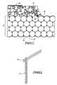
- FIG. 2exemplifies an arrangement of the component elements of the composite material structure as according to the invention
- FIG. 3illustrates a perspective view of a composite material as according to FIG. 2 further including a spacer for supporting the elongated rods in a symmetrical and spaced-apart fashion;
- FIG. 4illustrates a composite material structure formed using extrudate material layers having undulating surfaces
- FIGS. 5 and 6illustrate extrudate rods formed in other exemplary geometric shapes and arranged in stacked configurations
- FIG. 7illustrates a slurry material mixing/dispensing apparatus
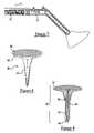
- FIG. 8exemplifies a fastener for use with the composite material structure of the present invention.
- FIG. 9exemplifies a second fastener for use with the composite material structure of the present invention.
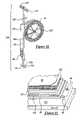
- FIG. 10illustrates a power tool for use in installing the fasteners in the composite material structure
- FIG. 11is an elevated view of an alternative embodiment of an inventive roofing installation.
- the present inventionhas utility as a building structural material operative as siding or roofing assembly. Use is optionally also made herein of waste foamed plastics.
- extrudate material operative in the present inventionis formed through the compaction of chips or flakes, or other high dimensional aspect ratio forms of waste foamed polymeric material.
- the waste foamed polymeric materialillustratively including plates, food trays, cups, packing peanuts, scrap, and combinations thereof.
- a process for preparing chopped wasteincludes washing the waste, if necessary to remove debris that will interfere with cementitious bonding to the foamed polymeric material, followed by feeding the material into a chopper to form particulate having at least one anisotropic axis. It is appreciated that the application of heat in the form of steam will further expand the polymeric material.
- the chopped polymeric materialis then mixed with an inorganic cementitious slurry and compressed to form an oriented polymeric cement board or other preform structure.
- an inorganic cementitious slurrynecessary to form a chopped foam material structure varies with variables such as anisotropic-shape, -size, -surface area, and cement viscosity.
- an inorganic cementitious slurryis effective in producing a shredded component structure with the addition of from 5 to 40 volume percent relative to the amount of chip material present.
- the slurryis present from 10 to 30 volume percent for typical roofing installations.
- the resulting board or other structureis well suited for assembly in the field through coating with inorganic cementitious slurries to form a lightweight roofing material. Additionally, the resulting preform is amenable to machining operations to form more intricate forms such as roofing shakes, siding, or complex shapes preformed to match the contours of a substrate. Alternatively, preformed rods or boards are readily coated with inorganic cementitious slurries upon production to form completed roofing or siding subassembly components such as boards, shakes or the like that are delivered to a structure and immediately applied thereto.
- the coating of individual rods or boards according to the present invention with an inorganic cementitious slurry with compression of the mass prior to slurry setupis effective in controlling air voids within a preassembled structure according to the present invention.
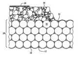
- FIG. 1illustrates a cross section of an inventive roofing installation shown generally at 1 .
- a composite material structure 10has large portions of additive material aligned over a substantial width of a material structure formed into rods or boards that occupy a large percentage of the structure volume.
- the structure 10is formed to fill the flutes of an underlying metal deck D. It is appreciated the distribution of forces over the body of a material structure enhances the structure's load bearing capabilities as compared to applying a concentrated force to a similar body.
- the present inventionrelies on this principle in providing a resiliently rigid and durable composite material structure having large portions of additive material symmetrically aligned over a substantial width of a material structure and occupying a large percentage of the structure volume.
- the composite material structure 10has utility as building material for use in commercial, residential and/or industrial applications.
- the composite material structure 10 as according to the inventionincludes a resilient layer 12 that provides a base or support surface for the composite material structure.
- the layer 12is formed from foamed insulated materials and other types of conventional materials known to those skilled in the art may be used which illustratively include rigid lightweight and durable materials such as foamed polystyrene, polyisocyanate, expanded perlite containing insulations, cardboard, polymer compounds, particleboard, and the like. In this case, it is desired for its insulative and shock-absorbing properties as well as its light weight. Plastic foam is exceptionally durable, making it effective as a protective material in a variety of applications such as packing, building and/or insulating material.
- foamis made up of more than 90% closed cell gaseous volume of air, carbon dioxide, or other gases, and due to its extremely low weight and durability, it is frequently desired as a construction material.
- all the foamed elements used to construct the composite material structure hereinare formed from recycled waste material such as disposable lunch trays, packing materials, carpet fibers, beverage cups, and carry-out containers or alternatively, a thermoplastic material having a well defined glass transition temperature is readily melted and extrusion spun into a fiber operative in the present invention.
- the waste materialis recycled according to conventional processes wherein substantially all of the waste material is converted into a usable valuable product rather than landfill.
- a thin layer of slurry material 14is disposed on a surface of the layer 12 or metal deck D to provide an adhesive layer on which additive materials may be disposed in forming the composite material structure.
- the slurry material 14is a cementitious material and illustratively includes calcium sulfate hemihydrate (gypsum), Portland, magnesia cements, aluminum calcite, and most preferably, a magnesia cementitious material such as magnesium oxychloride, magnesium oxysulfate (MOS) or magnesium phosphate cement (MAP).
- a cementis modified with various conventional additives illustratively including polymeric colloidal particulate, emulsion, surfactants, and air entrainment to yield a variety of physical properties for various applications.
- the composite material structure 10includes a plurality of elongated rods 16 as the additive material used to fill the bulk of the volume of the material structure.
- the elongated rods 16are arranged on the layer 12 or metal deck D coated with a thin layer of slurry material 14 to form at least one rod layer.
- the elongated rods 16are made of an extruded foamed plastic material; however, it is appreciated that other materials are optionally substituted therefor, these illustratively include polymer fibers, plastic tubing, metal tubing, and straw.
- the material used to form the rods 16comprises a carbonate compound additive that is operative to release carbon dioxide gas upon reaching a decomposition temperature.
- a small percentage of finely ground dolomitecan be added to the extrudate resin before expansion such that these powders will be suspended in the cell walls of the foamed extrudate material and will be responsible for the release of carbon dioxide gas from the formed elongated rods 16 in the event of a fire contacting the composite material structure 10 .
- a post-extrudate fire-resistant powdere.g. dolomite, calcium carbonate, calcium oxide, talc, or magnesium hydroxide, may be disposed on the surface of the elongated rods of the composite material structure 10 .
- the elongated rods 16may be arranged in spaced-apart symmetrical fashion through the utilization of spacers 22 that support the elongated rods 16 within the composite material 10 .
- the voids formed between the adjacent rodsare filled with the slurry material 14 and allowed to set such that the layer 12 and elongated rods are securely bound together to form the composite material structure.
- the composite material structure 10is disposed with a combination of slurry and polyester fabric that forms a resilient shock-absorbing layer that adds to the durability of the composite material.
- Other materialsmay be used for such purposes illustratively including synthetic fibers, saw dust, finely ground plastic aggregate, or other lightweight shock-absorbent materials.
- the structure 10is overlayered with an inorganic cementitious slurry of a thickness of greater than 0.2 centimeters.
- the overlying slurry 18has a thickness of between 0.3 and 2 centimeters.
- the overlying slurry 18incorporates a polymeric fiber, polymeric, mat, inorganic fiber, or inorganic mat in instances where additional strength is required.
- a foamed or otherwise expanded polystyrene insulation board of conventional design or that formed of waste regrind according to the present invention 19is applied thereover.
- the board 19has a thickness commensurate with the insulation factor desired for the inventive roofing installation 1 .
- the insulation board 19is overcoated with an additional layer of composite material structure 10 A.
- structure 10 Ais aligned with the elongated rods thereof being nonparallel to those of structure 10 . It is appreciated that while the installation 1 depicted in FIG. 1 has only a single insulation board 19 and structure 10 A, that these two layers in combination can be repeated multiple times within an inventive installation. In the instance where repetitive insulation board and structure layers 10 A are present, it is preferred that the orientation of the rods within each of the layers 10 A varies relative to other structure layers 10 A.
- a resilient layer 12 Acomparable to previously described layer 12 overlies structure 10 A.
- a conventional elastomeric layer 20is applied over layer 12 A in order to inhibit water intercalation.
- inventive rods 16have been depicted as circular in cross section, it is appreciated that this shape is only exemplary and various other cross sections are operative herein illustratively including triangular, rectilinear, pentagonal, hexagonal, non-regular variants thereof, and combinations thereof.
- the elongated rods 16are formed as a sheet having undulating surfaces that upon stacking interlock inorganic cementitious slurry therebetween to form a structure 10 as detailed above.
- FIGS. 5 and 6illustrate two other examples of the many geometric shapes that the extrudate rods may be formed whereby the exterior surfaces of the adjacent rods abut complementarily such that stacking results in the formation of a composite material structure 10 .
- the rods 16undergo a preprocessing step of being wet with a spray of inorganic slurry before being stacked on the substrate layer 12 .
- the slurry 14can be made to set in thin sheets and then milled to granules and optionally combined with a expanded polystyrene (EPS) dust. This mixture can be sprinkled on the surface of the wet rod and EPS board assembly.
- EPSexpanded polystyrene
- the first rod layercan be arranged on the substrate layer 12 in a more precise fashion due to the adhesive properties of the slurry material 14 that coats the surface of each elongated rod 16 and to further aid in field installation to like slurries.
- each elongated rod 16is one-eighth inch thick; however, other thicknesses may be utilized dependent on the application such that the desired durability and strength is provided.
- the layer 12 used to form the composite material structures 10is two feet by four feet, width by length, and of adequate thickness such that the substrate layer 12 provides an adequate support surface for the composite material structure 10 .
- FIG. 7is illustrative of a mixing/dispensing apparatus 70 for the slurry material used with the composite material structure 10 .
- the apparatus 70receives dry EPS regrind and inorganic slurry materials through separate delivery channels 71 and 72 , respectively in a mixing chamber 73 equipped with a slurry jet 74 to assure regrind wetting.
- Mixingis accomplished via an auger terminating in a dispensing nozzle 76 that regulates dispensing at a predetermined rate.
- the augeris a pair of twin augers 75 with reversed intermeshed threads to promote regrind wetting and extrusion of the material.
- FIGS. 8 and 9illustrate fastening elements 80 and 90 respectively which may be used with the composite material structure 10 in order to secure a foamed insulation board thereto with or without a wet slurry 18 as shown in FIG. 1 .
- FIG. 8illustrates a fastener 80 having a shaft that includes serrated edges 82 for opposing extraction after insertion and an insulation board cap 84 .
- the fastener 80has a slurry receiving grid 86 .
- FIG. 9illustrates a fastener 90 having an elongated shaft 92 terminating in a point 94 for ease of insertion into the composite material structure and an H-shaped cross section.
- the shaft 92has serrations 93 therealong.
- the fastener 90has an insulation board cap 96 .
- the cap 96is a separate piece relative to the shaft 92 .
- the cap 96has an interior bevel 98 that engages the serrations 93 and preferably a flare 99 extending towards the cap end 100 so as to define a slurry receiving cavity 102 .
- a fasteneris constructed of either metal or plastic, or combination thereof.
- metal fastenerit is appreciated that adhesion of cementitious materials thereto is facilitated by a polymeric coating.
- Nitrile plasticsare well suited for the formation of a plastic fastener.
- FIG. 10depicts an insertion tool suitable for the rapid installation of a fastener 90 .
- the toolis shown generally at 110 and includes a spool 112 of continuous shaft material 92 .
- the shaft material 92is fed through the core 114 of the elongated tool body 116 .
- a tube 118is mounted on the body 116 for the storage of caps 96 .
- a spring-mounted lever 120strips a cap 96 from the tube 118 and places the cap 96 in concentric alignment with the shaft material 92 extending from the base 120 of the body 116 .
- the application of pressure to the footrest 124ejects a punch 126 through the underlying substrate 12 or decking D to a create a pilot hole concentric with cap 96 and the shaft material 92 .
- the shaft material 92is then driven into engagement with the cap 96 and the underlying substrate and composite material structure 10 .
- a cutter 128is activated after placement of the fastener 90 through closure of a lever 129 prox
- FIG. 11The alternate embodiment of the inventive roofing installation is depicted in FIG. 11 at 150 where like numerals correspond to those detailed with respect to the aforementioned figures.
- Conventional foam plastic insulation 152is secured to an underlying resilient substrate 12 or decking D with the use of an inventive fastener 80 or 90 or a conventional fastener.
- a layer of inorganic cementitious slurry 18overlies the foam plastic insulation 152 and serves to adhere an overlying oriented polymeric cement board 154 .
- a second layer of inorganic cementitous slurry 18 ′ overlying the oriented polymeric cement board 154adheres a fiber mat material 156 , where the fiber mat 156 is either woven or non-woven.
- the fiber mat 156is optionally overcoated with an elastomeric roof coating 20 .
- the present inventionprovides a composite material structure wherein large portions of an additive material are aligned over a substantial width of a material structure whereby a larger percentage of the structure volume is filled by the additive material resulting in a more durable yet lightweight material structure.
Landscapes
- Engineering & Computer Science (AREA)
- Structural Engineering (AREA)
- Laminated Bodies (AREA)
Abstract
Description
Claims (11)
Priority Applications (1)
| Application Number | Priority Date | Filing Date | Title |
|---|---|---|---|
| US10/837,284US7169464B2 (en) | 2003-04-30 | 2004-04-30 | Aligned extrudate structure |
Applications Claiming Priority (2)
| Application Number | Priority Date | Filing Date | Title |
|---|---|---|---|
| US46688103P | 2003-04-30 | 2003-04-30 | |
| US10/837,284US7169464B2 (en) | 2003-04-30 | 2004-04-30 | Aligned extrudate structure |
Publications (2)
| Publication Number | Publication Date |
|---|---|
| US20050008810A1 US20050008810A1 (en) | 2005-01-13 |
| US7169464B2true US7169464B2 (en) | 2007-01-30 |
Family
ID=33567382
Family Applications (1)
| Application Number | Title | Priority Date | Filing Date |
|---|---|---|---|
| US10/837,284Expired - Fee RelatedUS7169464B2 (en) | 2003-04-30 | 2004-04-30 | Aligned extrudate structure |
Country Status (1)
| Country | Link |
|---|---|
| US (1) | US7169464B2 (en) |
Cited By (5)
| Publication number | Priority date | Publication date | Assignee | Title |
|---|---|---|---|---|
| US20080213562A1 (en)* | 2006-11-22 | 2008-09-04 | Przybylinski James P | Plastic Composites Using Recycled Carpet Waste and Systems and Methods of Recycling Carpet Waste |
| US20100159213A1 (en)* | 2008-12-19 | 2010-06-24 | Przybylinski James P | Wood-Plastic Composites Utilizing Ionomer Capstocks and Methods of Manufacture |
| US7875655B2 (en) | 2006-01-20 | 2011-01-25 | Material Innovations, Llc | Carpet waste composite |
| US11572646B2 (en) | 2020-11-18 | 2023-02-07 | Material Innovations Llc | Composite building materials and methods of manufacture |
| US12172421B2 (en) | 2020-11-18 | 2024-12-24 | Rise Building Products Llc | Composite building materials and methods of manufacture |
Families Citing this family (6)
| Publication number | Priority date | Publication date | Assignee | Title |
|---|---|---|---|---|
| US6896557B2 (en)* | 2001-03-28 | 2005-05-24 | Ortronics, Inc. | Dual reactance low noise modular connector insert |
| US20100136269A1 (en)* | 2005-11-01 | 2010-06-03 | E. Khashoggi Industries, Llc | Extruded fiber reinforced cementitious products having wood-like properties and ultrahigh strength and methods for making the same |
| US20080099122A1 (en)* | 2006-11-01 | 2008-05-01 | E. Khashoggi Industries Llc | Cementitious composites having wood-like properties and methods of manufacture |
| EP2017075A1 (en)* | 2007-07-20 | 2009-01-21 | Sika Technology AG | Insulating board and method for its production |
| US11186993B2 (en)* | 2017-10-24 | 2021-11-30 | Thomas L. Kelly | Enhanced roofing cover board |
| CN112431129A (en)* | 2020-11-26 | 2021-03-02 | 贵州磷镁材料有限公司 | Root-resistant waterproof structure |
Citations (22)
| Publication number | Priority date | Publication date | Assignee | Title |
|---|---|---|---|---|
| US3808085A (en)* | 1971-11-11 | 1974-04-30 | Battelle Development Corp | Concrete structural member |
| US3971075A (en) | 1974-05-08 | 1976-07-27 | Heinbaugh Kenneth D | Swimming pool structure |
| US4128369A (en) | 1975-12-10 | 1978-12-05 | Hazelett Strip-Casting Corporation | Continuous apparatus for forming products from thermoplastic polymeric material having three-dimensional patterns and surface textures |
| US4128975A (en)* | 1975-09-05 | 1978-12-12 | Solai Vignola Di Fabiani Orlando E C. - Societa In Nome Collettivo | Prefabricated building components of expanded material and cement |
| US4295316A (en) | 1977-05-02 | 1981-10-20 | Aluminum Company Of America | Nestable building wall panel |
| US4306395A (en) | 1978-06-01 | 1981-12-22 | Carpenter Orval R | Lightweight cementitious product and method for making same |
| US4399186A (en) | 1981-12-29 | 1983-08-16 | Owens-Corning Fiberglas Corporation | Foamed asphalt weathering sheet for roll roofing, siding, or shingles |
| US4817358A (en) | 1983-07-18 | 1989-04-04 | Owens-Corning Fiberglas Corporation | Asphalt shingle with foamed asphalt layer under tabs |
| US4884682A (en) | 1984-04-30 | 1989-12-05 | Highland Manufacturing And Sales Company | System for baling strands of material and a denser bale of strands of material so produced |
| US5094058A (en) | 1988-04-01 | 1992-03-10 | Slocum Donald H | Roofing shingle |
| US5295340A (en) | 1993-04-05 | 1994-03-22 | Pacific Coast Building Products, Inc. | Dimensional shingle for hip, ridge and rake portions of a roof |
| US5482550A (en) | 1991-12-27 | 1996-01-09 | Strait; Mark C. | Structural building unit and method of making the same |
| US5603758A (en) | 1995-10-06 | 1997-02-18 | Boral Concrete Products, Inc. | Composition useful for lightweight roof tiles and method of producing said composition |
| US5622556A (en) | 1994-12-19 | 1997-04-22 | Shulman; David M. | Lightweight, low water content cementitious compositions and methods of their production and use |
| US5631053A (en)* | 1992-08-11 | 1997-05-20 | E. Khashoggi Industries | Hinged articles having an inorganically filled matrix |
| US5641584A (en) | 1992-08-11 | 1997-06-24 | E. Khashoggi Industries | Highly insulative cementitious matrices and methods for their manufacture |
| US5846894A (en) | 1996-03-18 | 1998-12-08 | The University Of Chicago | Phosphate bonded structural products from high volume wastes |
| US6030446A (en) | 1996-05-29 | 2000-02-29 | Peerless Block & Brick Co. | Cementitious compositions and lightweight structural units |
| US6035583A (en) | 1994-01-26 | 2000-03-14 | Papke; William R. | Extruded building and method and apparatus related to same |
| US6161354A (en) | 1998-11-12 | 2000-12-19 | Certainteed Corporation | Shaped polymeric articles |
| US6233892B1 (en) | 1997-10-25 | 2001-05-22 | The Namlyt Company | Structural panel system |
| US6245381B1 (en) | 1999-11-12 | 2001-06-12 | Michael G. Israel | Manufacture of composite roofing products with matrix formulated microbiocide |
- 2004
- 2004-04-30USUS10/837,284patent/US7169464B2/ennot_activeExpired - Fee Related
Patent Citations (25)
| Publication number | Priority date | Publication date | Assignee | Title |
|---|---|---|---|---|
| US3808085A (en)* | 1971-11-11 | 1974-04-30 | Battelle Development Corp | Concrete structural member |
| US3971075A (en) | 1974-05-08 | 1976-07-27 | Heinbaugh Kenneth D | Swimming pool structure |
| US4128975A (en)* | 1975-09-05 | 1978-12-12 | Solai Vignola Di Fabiani Orlando E C. - Societa In Nome Collettivo | Prefabricated building components of expanded material and cement |
| US4128369A (en) | 1975-12-10 | 1978-12-05 | Hazelett Strip-Casting Corporation | Continuous apparatus for forming products from thermoplastic polymeric material having three-dimensional patterns and surface textures |
| US4295316A (en) | 1977-05-02 | 1981-10-20 | Aluminum Company Of America | Nestable building wall panel |
| US4306395A (en) | 1978-06-01 | 1981-12-22 | Carpenter Orval R | Lightweight cementitious product and method for making same |
| US4399186A (en) | 1981-12-29 | 1983-08-16 | Owens-Corning Fiberglas Corporation | Foamed asphalt weathering sheet for roll roofing, siding, or shingles |
| US4817358A (en) | 1983-07-18 | 1989-04-04 | Owens-Corning Fiberglas Corporation | Asphalt shingle with foamed asphalt layer under tabs |
| US4884682A (en) | 1984-04-30 | 1989-12-05 | Highland Manufacturing And Sales Company | System for baling strands of material and a denser bale of strands of material so produced |
| US5094058A (en) | 1988-04-01 | 1992-03-10 | Slocum Donald H | Roofing shingle |
| US5482550A (en) | 1991-12-27 | 1996-01-09 | Strait; Mark C. | Structural building unit and method of making the same |
| US5631053A (en)* | 1992-08-11 | 1997-05-20 | E. Khashoggi Industries | Hinged articles having an inorganically filled matrix |
| US5641584A (en) | 1992-08-11 | 1997-06-24 | E. Khashoggi Industries | Highly insulative cementitious matrices and methods for their manufacture |
| US5295340A (en) | 1993-04-05 | 1994-03-22 | Pacific Coast Building Products, Inc. | Dimensional shingle for hip, ridge and rake portions of a roof |
| US6035583A (en) | 1994-01-26 | 2000-03-14 | Papke; William R. | Extruded building and method and apparatus related to same |
| US5622556A (en) | 1994-12-19 | 1997-04-22 | Shulman; David M. | Lightweight, low water content cementitious compositions and methods of their production and use |
| US5603758A (en) | 1995-10-06 | 1997-02-18 | Boral Concrete Products, Inc. | Composition useful for lightweight roof tiles and method of producing said composition |
| US5846894A (en) | 1996-03-18 | 1998-12-08 | The University Of Chicago | Phosphate bonded structural products from high volume wastes |
| US6030446A (en) | 1996-05-29 | 2000-02-29 | Peerless Block & Brick Co. | Cementitious compositions and lightweight structural units |
| US6233892B1 (en) | 1997-10-25 | 2001-05-22 | The Namlyt Company | Structural panel system |
| US6161354A (en) | 1998-11-12 | 2000-12-19 | Certainteed Corporation | Shaped polymeric articles |
| US6319456B1 (en) | 1998-11-12 | 2001-11-20 | Certainteed Corporation | Method for continuous vacuum forming shaped polymeric articles |
| US20010049918A1 (en) | 1998-11-12 | 2001-12-13 | Gilbert Thomas Charles | Staggered look shake siding |
| US20020033563A1 (en) | 1998-11-12 | 2002-03-21 | Certainteed Corporation. | Apparatus for continuous forming shaped polymeric articles |
| US6245381B1 (en) | 1999-11-12 | 2001-06-12 | Michael G. Israel | Manufacture of composite roofing products with matrix formulated microbiocide |
Cited By (17)
| Publication number | Priority date | Publication date | Assignee | Title |
|---|---|---|---|---|
| US8809406B2 (en) | 2006-01-20 | 2014-08-19 | Material Innovations Llc | Carpet waste composite |
| US10822798B2 (en) | 2006-01-20 | 2020-11-03 | Material Innovations Llc | Carpet waste composite |
| US7875655B2 (en) | 2006-01-20 | 2011-01-25 | Material Innovations, Llc | Carpet waste composite |
| US7923477B2 (en) | 2006-01-20 | 2011-04-12 | Material Innovations Llc | Carpet waste composite |
| US20110097552A1 (en)* | 2006-01-20 | 2011-04-28 | Material Innovations, Llc | Carpet waste composite |
| US20110229691A1 (en)* | 2006-01-20 | 2011-09-22 | Murdock David E | Carpet Waste Composite |
| US8278365B2 (en) | 2006-01-20 | 2012-10-02 | Material Innovations Llc | Carpet waste composite |
| US8455558B2 (en) | 2006-01-20 | 2013-06-04 | Material Innovations Llc | Carpet waste composite |
| US11773592B2 (en) | 2006-01-20 | 2023-10-03 | Material Innovations Llc | Carpet waste composite |
| US9637920B2 (en) | 2006-01-20 | 2017-05-02 | Material Innovations Llc | Carpet waste composite |
| US10294666B2 (en) | 2006-01-20 | 2019-05-21 | Material Innovations Llc | Carpet waste composite |
| US20080213562A1 (en)* | 2006-11-22 | 2008-09-04 | Przybylinski James P | Plastic Composites Using Recycled Carpet Waste and Systems and Methods of Recycling Carpet Waste |
| US9073295B2 (en) | 2008-12-19 | 2015-07-07 | Fiber Composites, Llc | Wood-plastic composites utilizing ionomer capstocks and methods of manufacture |
| US10875281B2 (en) | 2008-12-19 | 2020-12-29 | Fiber Composites Llc | Wood-plastic composites utilizing ionomer capstocks and methods of manufacture |
| US20100159213A1 (en)* | 2008-12-19 | 2010-06-24 | Przybylinski James P | Wood-Plastic Composites Utilizing Ionomer Capstocks and Methods of Manufacture |
| US11572646B2 (en) | 2020-11-18 | 2023-02-07 | Material Innovations Llc | Composite building materials and methods of manufacture |
| US12172421B2 (en) | 2020-11-18 | 2024-12-24 | Rise Building Products Llc | Composite building materials and methods of manufacture |
Also Published As
| Publication number | Publication date |
|---|---|
| US20050008810A1 (en) | 2005-01-13 |
Similar Documents
| Publication | Publication Date | Title |
|---|---|---|
| US10443238B2 (en) | High performance, reinforced insulated precast concrete and tilt-up concrete structures and methods of making same | |
| US7169464B2 (en) | Aligned extrudate structure | |
| US5002620A (en) | Method of production of fiber-reinforced cellular concrete | |
| US8065853B2 (en) | Reinforced cementitious shear panels | |
| KR100887460B1 (en) | Composite building materials | |
| US8105685B2 (en) | Roofing cover board, roofing panel composites, and method | |
| US20020014051A1 (en) | High strength light-weight fiber ash composite material, method of manufacture thereof, and prefabricated structural building members using the same | |
| US20110268916A1 (en) | Double Skin Composite Hybrid Structural Insulated Panel | |
| JP2004524465A (en) | How to make and install fiber cement siding | |
| CA2649808A1 (en) | Structural insulation sheathing | |
| WO2001075244A1 (en) | Insulated wall structure | |
| CA2212962A1 (en) | Insulating mortar | |
| CN212534795U (en) | Multilayer composite board | |
| WO2005090708A1 (en) | Composite decking | |
| CN206633142U (en) | Crosswise lamination wood plank | |
| CN2584702Y (en) | Compound fibre reinforced plaster wood chip wallboard | |
| WO2000014358A2 (en) | Foamed facer and insulation boards made therefrom | |
| CN2364102Y (en) | Light multifunction composite wall panel | |
| CN111379376A (en) | Multilayer composite board and manufacturing method thereof | |
| KR20250078439A (en) | Multi-material cladding system | |
| JPH0614317U (en) | Special reinforced lightweight precast synthetic board |
Legal Events
| Date | Code | Title | Description |
|---|---|---|---|
| AS | Assignment | Owner name:ALIGNED EXTRUDATE STRUCTURE, CALIFORNIA Free format text:ASSIGNMENT OF ASSIGNORS INTEREST;ASSIGNOR:SEMMENS, BLAINE K.;REEL/FRAME:017786/0847 Effective date:20040430 | |
| AS | Assignment | Owner name:CONSERVATION ROOFING SYSTEMS, INC., CALIFORNIA Free format text:CORRECTIVE COVERSHEET TO CORRECT THE NAME OF THE ASSIGNEE PREVIOUSLY RECORDED ON REEL 011786, FRAME 0847.;ASSIGNOR:SEMMENS, BLAINE K.;REEL/FRAME:018001/0281 Effective date:20040430 | |
| AS | Assignment | Owner name:MOS, L.L.C., WASHINGTON Free format text:ASSIGNMENT OF ASSIGNORS INTEREST;ASSIGNOR:CONSERATION ROOFING SYSTEMS, INC.;REEL/FRAME:018013/0090 Effective date:20060127 | |
| AS | Assignment | Owner name:CONSERVATION ROOFING SYSTEMS, INC., CALIFORNIA Free format text:ASSIGNMENT OF ASSIGNORS INTEREST;ASSIGNOR:MOS, LLC;REEL/FRAME:018646/0213 Effective date:20061121 | |
| REMI | Maintenance fee reminder mailed | ||
| FPAY | Fee payment | Year of fee payment:4 | |
| SULP | Surcharge for late payment | ||
| REMI | Maintenance fee reminder mailed | ||
| LAPS | Lapse for failure to pay maintenance fees | ||
| STCH | Information on status: patent discontinuation | Free format text:PATENT EXPIRED DUE TO NONPAYMENT OF MAINTENANCE FEES UNDER 37 CFR 1.362 | |
| FP | Expired due to failure to pay maintenance fee | Effective date:20150130 |