US7169355B1 - Apparatus and method for ejecting sample well trays - Google Patents
Apparatus and method for ejecting sample well traysDownload PDFInfo
- Publication number
- US7169355B1 US7169355B1US09/496,408US49640800AUS7169355B1US 7169355 B1US7169355 B1US 7169355B1US 49640800 AUS49640800 AUS 49640800AUS 7169355 B1US7169355 B1US 7169355B1
- Authority
- US
- United States
- Prior art keywords
- sample
- sample well
- well tray
- cover
- block
- Prior art date
- Legal status (The legal status is an assumption and is not a legal conclusion. Google has not performed a legal analysis and makes no representation as to the accuracy of the status listed.)
- Expired - Lifetime, expires
Links
Images


Classifications
- B—PERFORMING OPERATIONS; TRANSPORTING
- B01—PHYSICAL OR CHEMICAL PROCESSES OR APPARATUS IN GENERAL
- B01L—CHEMICAL OR PHYSICAL LABORATORY APPARATUS FOR GENERAL USE
- B01L3/00—Containers or dishes for laboratory use, e.g. laboratory glassware; Droppers
- B01L3/50—Containers for the purpose of retaining a material to be analysed, e.g. test tubes
- B01L3/508—Containers for the purpose of retaining a material to be analysed, e.g. test tubes rigid containers not provided for above
- B01L3/5085—Containers for the purpose of retaining a material to be analysed, e.g. test tubes rigid containers not provided for above for multiple samples, e.g. microtitration plates
- B—PERFORMING OPERATIONS; TRANSPORTING
- B01—PHYSICAL OR CHEMICAL PROCESSES OR APPARATUS IN GENERAL
- B01L—CHEMICAL OR PHYSICAL LABORATORY APPARATUS FOR GENERAL USE
- B01L7/00—Heating or cooling apparatus; Heat insulating devices
- B01L7/52—Heating or cooling apparatus; Heat insulating devices with provision for submitting samples to a predetermined sequence of different temperatures, e.g. for treating nucleic acid samples
- Y—GENERAL TAGGING OF NEW TECHNOLOGICAL DEVELOPMENTS; GENERAL TAGGING OF CROSS-SECTIONAL TECHNOLOGIES SPANNING OVER SEVERAL SECTIONS OF THE IPC; TECHNICAL SUBJECTS COVERED BY FORMER USPC CROSS-REFERENCE ART COLLECTIONS [XRACs] AND DIGESTS
- Y10—TECHNICAL SUBJECTS COVERED BY FORMER USPC
- Y10S—TECHNICAL SUBJECTS COVERED BY FORMER USPC CROSS-REFERENCE ART COLLECTIONS [XRACs] AND DIGESTS
- Y10S435/00—Chemistry: molecular biology and microbiology
- Y10S435/809—Incubators or racks or holders for culture plates or containers
- Y—GENERAL TAGGING OF NEW TECHNOLOGICAL DEVELOPMENTS; GENERAL TAGGING OF CROSS-SECTIONAL TECHNOLOGIES SPANNING OVER SEVERAL SECTIONS OF THE IPC; TECHNICAL SUBJECTS COVERED BY FORMER USPC CROSS-REFERENCE ART COLLECTIONS [XRACs] AND DIGESTS
- Y10—TECHNICAL SUBJECTS COVERED BY FORMER USPC
- Y10S—TECHNICAL SUBJECTS COVERED BY FORMER USPC CROSS-REFERENCE ART COLLECTIONS [XRACs] AND DIGESTS
- Y10S436/00—Chemistry: analytical and immunological testing
- Y10S436/807—Apparatus included in process claim, e.g. physical support structures
- Y10S436/809—Multifield plates or multicontainer arrays
Definitions
- the present inventionrelates to an apparatus and method for ejecting sample well trays from a heating apparatus for biological samples.
- the apparatusimproves the process of removing a sample well tray from a sample block after the cover of the heating apparatus is opened.
- Biological testinghas become an important tool in detecting and monitoring diseases.
- thermal cyclingis utilized in order to perform polymerase chain reactions (PCR) and other reactions.
- PCRpolymerase chain reactions
- a specifically constituted liquid reaction mixtureis cycled through a PCR protocol including several different temperature incubation periods.
- An aspect of the PCR processis the concept of thermal cycling: alternating steps of melting DNA, annealing short primers to the resulting single strands, and extending those primers to make new copies of double-stranded DNA.
- thermal cyclingit is desirable that the temperature of each of a plurality of sample wells are substantially identical.
- condensationis avoided on the caps or other covering for the sample wells.
- a common method of inhibiting condensation on the top of the sample wellsis to provide a heated platen for pressing down on the tops or caps of the sample well trays.
- the platenis typically included as part of a cover and is typically metal. The platen transfers heat to the caps of the sample wells, thereby inhibiting condensation.
- the platenpresses down on the sample wells so that the sample well outer conical surfaces are pressed firmly against the mating surfaces on the sample block. This increases heat transfer to the sample wells, and assists in providing a more uniform distribution of sample well temperatures.
- the platenalso prevents thermal leakage from the interior of the device. Examples of a system with a platen and heated cover are described in U.S. Pat. Nos. 5,475,610, 5,602,756, and 5,710,381, all of which are assigned to the assignee of the present invention, and the contents of which are all hereby incorporated by reference herein.
- sample well trayscan stick inside of the sample block due to expansion of the sample well trays and due to the force imparted on the trays by the thermal cycler cover. A considerable force may be required to unstick the sample wells and tray from the sample block and remove the tray.
- laboratory robotic systems for removing sample well trayscan sometimes have difficulty generating sufficient force to remove the sample well trays from the sample block. With the increase in the popularity of laboratory automation, it is particularly desirable to make the thermal cyclers more compatible to robotic removal of the sample well trays from the sample block. It is also desirable to increase the throughput of these devices.
- the inventionincludes a heating apparatus for biological samples.
- the heating apparatus of the present inventionincludes a cover, a sample block having a plurality of openings in a top portion thereof for receiving a sample well tray having a plurality of sample wells, and an urging mechanism.
- the urging mechanismis positionable between the sample block and the sample well tray to urge the sample well tray away from the sample block when the cover is moved from a closed position toward an open position.
- the coverimparts a downward force on the top of the sample well tray to press the sample wells into the openings of the sample block when the heated cover is moved toward a closed position.
- the urging mechanismimparts an upward force on the sample well tray.
- the downward force imparted by the heated coveris sufficient to retain the sample well tray against the sample block when the cover is in the closed position.
- the urging mechanismis attached to the sample block. In an alternate embodiment, the urging mechanism is attached to a sample well tray holder.
- the inventionin another aspect, includes a system for urging a sample well tray away from a sample block.
- the systemincludes a sample block having a plurality of openings for receiving sample wells of a sample well tray therein, and at least one urging mechanism interposed between the sample block and sample well tray to urge the sample wells away from the openings in the sample block.
- the inventionincludes a method of manipulating a sample well tray with respect to a sample block.
- the methodincludes the step of providing an initial downward force on a sample well tray, the initial downward force pressing sample wells of the sample well tray into openings on a top surface of a sample block; and the step of providing an upward force on the sample well tray.
- the methodmay further include the steps of reducing the initial downward force on the sample well tray, and urging the sample well tray from the sample block by an upward force between the sample well tray and the sample block.
- the inventionincludes a mechanism for urging a sample tray away from a sample block in a biological sample heating device.
- the mechanismincludes a spring positioned between the sample block and sample tray. The spring has a sufficient force in a compressed state to move the sample tray in a direction substantially away from the sample block in response to opening a cover away from the sample tray.
- FIG. 1shows a perspective view of a thermal cycler system according to the invention, with a cover in an open position;
- FIG. 2shows a close-up perspective view of a sample block and sample well tray of the system of FIG. 1 ;
- FIG. 3shows a partial top view of the sample block of FIG. 2 with the sample well tray removed;
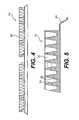
- FIG. 4shows a sectional view of the sample block along line IV—IV of FIG. 3 ;
- FIG. 5shows a sectional view of the sample block along line V—V of FIG. 3 ;
- FIG. 6shows a perspective view of the sample block of FIG. 3 ;
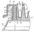
- FIG. 7shows a sectional view of the sample well tray and sample block along line VII—VII of FIG. 2 ;
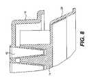
- FIG. 8shows a sectional view of the sample well tray and sample block along line VIII—VIII of FIG. 2 ;
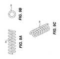
- FIGS. 9A , 9 B, and 9 Cshow a side view, a top view, and a perspective view, respectively, of an ejection spring for the thermal cycler of FIG. 1 ;
- FIGS. 10A , 10 B, and 10 Cshow a side view, a top view, and a perspective view, respectively, of a second ejection spring for the thermal cycler of FIG. 1 ;
- FIG. 11shows a perspective view of a sample well tray, sample well tray holder, and sample block according to a second embodiment of the present invention
- FIG. 12shows a perspective view of the apparatus of FIG. 11 including a cover and a base
- FIG. 13shows a schematic illustrating the operation of the apparatus of FIGS. 11–12 .
- a heating apparatus for biological samplesincludes a heated cover, a sample block having a plurality of openings, a sample well tray or plate having a plurality of sample wells, and an urging mechanism positioned between the sample block and the sample well tray to urge the sample well tray away from the sample block when the heated cover is moved from a closed position to an open position.
- the heating apparatus 10 for biological samplesincludes a heated cover 12 , a sample block 14 , a sample well tray 16 , and an urging mechanism 18 .
- the heating apparatus 10may be any type of conventional heating device for thermally heating biological samples.
- the heating apparatusis a thermal cycler, specifically, a dual 384-well PE Biosystem 9700 thermal cycler system sold by PE Biosystems.
- the thermal cycler 10 shown in the first embodimentuses two 384-well sample well trays 16 , however, the present invention is suitable with any of the other common configurations, such as a single 384-well configuration, a dual 96-well configuration, a single 96-well configuration, or a 60-well configuration.
- the present inventionis also suitable with other configurations with any number of sample wells ranging from one sample well to several thousand sample wells.
- the specific type of heating apparatusis not a part of the instant invention, and is shown for purposes of illustration only.
- the present inventionis suitable for any type of heating apparatus in which sample wells are pressed into a sample block by a cover.
- the present inventionis especially suitable for use in a heating apparatus with a heated cover.
- trays with sample wellsmay have a flat surface on which a sample of biological material is placed.
- the flat surface on which the sample is placedmay be similar to a microscope slide for a sample.
- a liquidmay be dropped onto the tray at a plurality of positions, and then a film or cover positioned on the top surface of the tray over the samples.
- a sample traymay include a porous material such a frit on the top surface, instead of sample wells, for holding samples of biological material. Therefore, although the description refers to sample well trays throughout, it should be understood that the present invention is also suitable for sample trays that do not have sample wells.
- the heating apparatusincludes a heated cover.
- the heated cover 12is located above the sample block 14 and sample well tray 16 .
- the heated coveris operable between an open position, as shown in FIG. 1 , and a closed position where the heated cover is placed over the sample block and sample well tray.
- the heated coveris maintained in an open position during insertion of the sample well tray into the sample block, and is then closed during operation of the heating apparatus, i.e., thermal cycling.
- the heated coverIn the open position, the heated cover does not engage the top of the sample well tray 16 .
- a closed positionthe heated cover 12 presses down on the top portion of the sample well tray 16 , thereby providing a downward force on the sample well tray.
- each sample well of sample well tray 16is typically defined by a cap, adhesive film, heat seal, or gap pad.
- a gap pad(not shown) is provided between a platen of the heated cover and the top surface of the sample well tray. The gap pad improves the distribution of the downward force on the top of the sample wells.
- the gap padis a MJ Research “Microseal P Type” silicon rubber plate. The gap pad will typically adhere to the platen. The gap pad may be used by itself, or in conjunction with an adhesive film or heat-sealed film.
- the type of cover for the sample welldepends on the specific application and is not important for the purpose of the present invention.
- the gap padmay be used in conjunction with caps on the top portion of the sample wells.
- the capsmay be connected in strips, or may be individually provided as separate, unconnected caps for each sample well. Alternately, caps may be used without the gap pad. Because all of these methods can be referred to as “capping” the sample wells, the remainder of the specification will refer to the structure immediately over the sample wells as a cap, regardless of whether it is a film, pad, or cap. The basic concepts of the invention are equally applicable on each of these arrangements.
- the heated coverreduces heat transfer from the liquid sample by evaporation.
- the heated coveralso reduces the likelihood of cross contamination by keeping the insides of the caps dry, thereby preventing aerosol formation when the wells are uncapped.
- the heated covermaintains the caps above the condensation temperature of the various components of the liquid sample to prevent condensation and volume loss of the liquid sample.
- the heated covermay be of any of the conventional types known in the art.
- the heated coveris physically actuated to and from a closed position by a motor.
- the heated coveris slid into and out of a closed position by manual physical actuation.
- the heated covertypically includes at least one heated platen (not shown) for pressing against the top surface of the sample well trays. Details of the heated covers and platens are well known in the art, and are described for example in U.S. Pat. Nos. 5,475,610, 5,602,756, and 5,710,381, all of which are assigned to the assignee of the present invention, and the contents of which are all hereby incorporated by reference herein. While the present invention is described for use with a heated cover, the present invention also performs suitably with a cover which is not heated.
- the heating apparatusincludes at least one sample block and corresponding sample well tray.
- the sample block 14includes a plurality of openings 20 in a top portion thereof for receiving sample wells of the sample well tray.
- each of the sample block openingsmay have a conical shape which is sized to fit with a sample well of a sample well tray.
- the sample block openingsmay be other shapes such as cylindrical or hemispherical, depending on the shape of the mating sample wells.
- Sample blocksare well known in the art. Sample blocks may be a variety of materials, although metals such as aluminum or aluminum alloy are often preferred.
- the sample blockis typically machined out of a solid block of material, however casting and other techniques are also well known. It is desirable that the sample block exhibits a substantially uniform temperature across the sample well openings 20 , and that the openings maintain close tolerances with the sample wells that are inserted therein.
- sample blocks shown in the embodiment of FIGS. 1–10have 384 openings arranged in a 16 ⁇ 24 array, however, any number of openings may be provided.
- Other common configurationsinclude 96 and 60-well sample blocks, although the present invention is suitable for sample well trays having anywhere from one sample well to several thousand sample wells.
- Sample block openings 20are positioned in a grid-like fashion on a top surface 22 of the sample block 14 .
- the openings 20are defined by a conical side wall 24 and a bottom wall surface 26 as best shown in FIGS. 5 and 7 .
- the conical side wall 24may slant at any appropriate angle known in the art.
- the size and shape of the openings shown in the drawingsis by way of example only. Other designs having a different arrangement of sample wells are equally suitable with the present invention.
- Sample block 14may include a bottom flange portion 28 for resting on the base 40 of the heating apparatus or any other alternate design.
- a compression seal(not shown) may be provided between the flange portion 28 and base 40 .
- the sample block of the present inventionfurther includes the provision of portions engageable with an urging mechanism of the present invention. The engageable portions of the sample block will be described in greater detail later in the specification.
- the sample well tray 16includes a plurality of sample wells 42 in a top surface 44 thereof, as best shown in FIG. 7 .
- Sample well trays suitable for the present inventionare well known in the art, and are also referred to as sample well plates.
- the present inventionis flexible so that virtually any type of sample well tray may be utilized.
- the sample wells 42 shown in the Figuresare of a conventional conical design known in the art.
- the sample wellsmay be of a variety of other shapes such as cylindrical or hemispherical.
- Each sample well 42can hold a predefined volume of liquid sample.
- each sample wellhas a total volume of approximately 30 ⁇ l and a working volume of approximately 20 ⁇ l.
- the sample wellshave a diameter of approximately 2.20 mm and a depth of approximately 8.0 mm.
- the volume and dimensions of the wellscan be varied depending on the specific application, as well as depending upon the number of sample wells for the sample well tray. For example, a 384-well sample well tray will typically have a smaller sample well volume than a 96-well sample well tray.
- the sample well traymay be made out of any of the conventional materials such as polypropylene that are typically used in sample well trays that will undergo thermal cycling of biological samples.
- the present inventionis also suitable with a sample tray where the wells are individual tubes that may be individually detached from the tray. Alternately, the tubes may be connected together in sets of rows or columns.
- the sample wells 42are designed to closely mate with the conical side walls 24 of the sample block, particularly after the heated cover applies a downward force on the sample well tray.
- FIG. 7shows the spacing between sample well tube walls 46 and the sample block side walls 24 in exaggerated form for illustration purposes only.
- sample well trayis typically made of a plastic material that is slightly deformable
- the sample wells of the sample well traywill also slightly deform to match the shape of the sample block openings 20 . This ensures that the sample wells of the sample well tray will closely fit against the sample block to enhance the temperature uniformity of the sample wells of the sample well tray.
- the sample well tube walls 46impart a force on the inside surface of the sample block side walls 24 .
- the sample wells 42 of the sample well trayhave a tendency to stick inside of the sample block openings 20 .
- a significant forcemay be required to loosen the sample well tray 16 from the sample block 14 .
- Robots used for sample well tray removaltypically only generate very weak linear forces. Robots typically are unable to impart the rocking motion which is helpful in removing the sample well trays from the sample block openings. Because the robots are typically limited to linear motions, instead of rotational motion, a much higher force is required in order to loosen the sample well tray from the sample block. The linear robot-generated forces are frequently inadequate to overcome the initial sticking force, therefore, the sample well tray may remain stuck in the sample block. Therefore, an operator may need to loosen the sample well tray from the sample block by manually prying the sample well tray from the sample block. Alternately, robots may be designed which are capable of imparting a rotational force on the sample well trays, however, these robots will typically be larger, slower, more complex, and more expensive than existing robots.
- the present inventionincludes an urging mechanism for urging the sample well tray away from the sample block.
- the urging mechanismtends to overcome the initial sticking force of the sample well tray in the sample block so that the sample well tray is loosened from the sample block without substantial manual or robotic assistance.
- the provision of the urging mechanism of the present inventionreduces the need for an operator to help unstick the sample well tray from the sample block, saving time, and reducing costs. Additionally, the robots used for automated handling do not need to be made unnecessarily more powerful and bulky, thereby saving cost and space.
- the urging mechanism of the present inventionmay have a variety of designs, one of which is shown in the embodiment of FIGS. 1–10 .
- the present inventionincludes urging mechanism 18 positioned between the sample block 14 and the sample well tray 16 to urge the sample well tray away from the sample block when the heated cover is moved from the closed position to an open position.
- the urging mechanismcomprises a plurality of first springs 50 and a plurality of second springs 60 , as best shown in FIG. 2 .
- the urging mechanism shown in FIGS. 1–10is by way of example only. The urging mechanism of the present invention is not limited to the example shown in the Figures.
- the first springs 50are positioned in a cylindrical spring opening 52 of the sample block in one embodiment of the present invention.
- the cylindrical opening 52is defined by the side surfaces 54 and end surface 56 of the cylindrical opening, as best shown in FIG. 7 .
- the springsmay be positioned on the top surface of the sample block without the provision of a cylindrical opening, depending on the amount of unsupported spring length.
- the urging mechanism shown in FIG. 7is a helical compression spring
- a variety of other types of urging mechanismsmay be utilized.
- springssuch as leaf springs, conical helical springs, and other springs which will import an axial force when compressed are suitable with the present invention.
- other spring-like devices suitable for useinclude, for example, elastomeric spring members, air cylinders, fluid cylinders, dampeners, belleville washers, and electrical solenoids. Any other suitable device that may be interposed in the system for imparting an upward force on the sample well tray may be used.
- the urging mechanismmerely needs to be designed so that it creates sufficient force to overcome the sticking force between the sample well tray and the sample block upon opening of the cover.
- the urging mechanismshould loosen the sample well tray from the sample block so that the sample well tray can be easily removed either robotically or manually. If a spring is used, the size and spring constant of the spring must be selected so an adequate force is imparted by the spring on the sample well tray.
- first spring 50abuts against the end surface 56 of cylindrical opening 52 in the sample block 14 , as best shown in FIG. 7 .
- the opposite end of spring 50engages the lower surface 58 of the sample well tray 16 .
- the Figuresshow the end surface 56 and lower surface 58 as being flat, other configurations may be used in order to more securely engage the spring.
- the end surface 56 of the cylindrical opening or the lower surface 58 of the sample well traymay include grooves to closely fit the interior and/or exterior of the spring.
- the urging mechanism 18includes a plurality of first springs 50 and a plurality of second springs 60 .
- the springsare positioned around an outer peripheral surface 62 of the sample block outside of the rectangular grid of sample block openings 20 , as best shown in FIG. 2 .
- six first springs 50are positioned on each longitudinal side (defined as the side with the greater number of sample well openings, for example, the side with twenty-four sample block openings in FIG. 2 ) of the outer peripheral top surface 62 of the sample well block.
- a set of second springs 60are positioned on each lateral side (defined as the side with the lesser number of sample well openings, for example, the side with sixteen sample block openings in FIG. 2 ) of the outer peripheral top surface 62 of the sample block outside of the grid of sample block openings.
- the second springs 60are positioned on projections 70 that extend outward from the rectangular array of sample block openings on each lateral side of the top surface.
- two second springs 60are located on each lateral side of the top surface.
- Each second spring 60has a projection 70 for resting thereon.
- the second springsare similar to the first springs, but may be greater in size.
- the second springs 60are typically positioned in cylindrical openings similar to those used for the first springs 50 , although the cylindrical openings may not be necessary in some arrangements. With the arrangement shown in FIGS. 1–10 , a total of sixteen springs (twelve first springs and four second springs) are utilized on the outer periphery of the sample block 16 . The number and specific arrangement of springs can be varied greatly depending on the specific application.
- the urging mechanismprovide a substantially uniform force on the sample well tray in order to reduce undue bending of the sample well tray.
- the forceis more evenly distributed, more lightweight and thinner sample well trays may be used. Therefore, costs can be reduced for the sample well tray production and materials if the urging mechanism distributes the upward force in a substantially uniform manner. If few, large force points were used, the tray may become locally deformed in a way that could affect the handling of the tray later in the process.
- the application of a substantially uniform spring force around the periphery of the sample well traymay help reduce evaporation losses from locations adjacent the periphery of the sample well tray by ensuring that the sample well tray is firmly and evenly placed against the heated cover. Therefore, in one embodiment, it is preferable to provide a large number of substantially uniformly spaced springs for the urging mechanism.
- Springs 50 and 60 of urging mechanism 18provide an upward force on the sample well tray that is sufficient to overcome the sticking force caused by the cover and loosen the sample well tray from the sample block upon opening of the cover.
- the upward force applied by the springsshould be less than the downward force applied by the cover or the cover will not remain closed.
- the downward force imparted by the coveris typically significantly greater than the upward force imparted by the springs in order to ensure good thermal contact between the sample wells of the sample well tray and the openings of the sample block.
- FIGS. 9A–9C and 10 A– 10 CAn example of suitable type springs used in one embodiment of the urging mechanism is shown in FIGS. 9A–9C and 10 A– 10 C.
- the springs of this embodimentare helical coil springs selected to impart sufficient force to urge the sample well tray away from and slightly out of the sample block after the cover is opened.
- the first springs 50have an outside diameter of 1.92 mm, length of 6.3 mm, and spring rate of 0.275 kg/mm. During closing of the cover, these first springs 50 each compress 1.15 mm thus imparting an ejecting force of 0.316 kg each.
- the second springs 60have an outside diameter of 3.05 mm, length of 9.53 mm, and spring rate of 0.987 kg/mm. During closing of the cover, these second springs 60 each compress 1.55 mm thus imparting an ejecting force of 1.53 kg.
- the particular springs used in the above examplewere made of stainless steel, however other suitable materials are also acceptable.
- the springsare preferably of a low thermal mass compared to the sample block and therefore do not materially affect the performance of the system. Therefore, the sample block and sample well tray maintain a substantially uniform temperature distribution that is not affected by the urging mechanism 18 .
- the heated cover 12 of the thermal cycleris positioned in a first open position.
- a sample well tray with a predetermined amount of liquid sample in some or all of the sample wellsis placed on top of the sample block.
- the sample well tray 16typically includes either an adhesive film, a heat seal film, a gap pad, or individual caps for covering each of the sample wells 42 at the time of insertion into the thermal cycler.
- the sample wells 42are aligned with the sample block openings and inserted downward into the conical sample block openings 20 .
- the heated coveris then slid so that it is placed over the sample well trays and sample block.
- the heated coveris then manually or automatically closed.
- a heated platen (or the gap pad located below the platen) of the heated cover 12presses down on the top of the sample wells to firmly press the sample wells 42 into the sample block openings 20 , as best shown in FIG. 7 .
- the first and second springs 50 and 60 of the urging mechanism 18are compressed by a bottom flat surface 58 of the sample well tray on the outside periphery of the sample wells 42 .
- the compression springsimpart an upward force on the sample well tray 16 while the heated cover is in its closed position. While in the closed position, the thermal cycler then thermally cycles the liquid sample in the sample well tray to undergo a PCR or other type of chemical reaction.
- the heated cover 12is opened (either manually or automatically). As the heated cover is opened, the platen (or gap pads) of the heated cover will no longer press against the top of the sample wells. Simultaneously, the springs of the urging mechanism 18 will impart an upward force on the bottom surface 58 of the sample well tray, thereby urging the sample wells 42 out of the sample block openings 20 . The springs should impart sufficient force so that the sample well tray 16 will become loosened from the sample block 14 and be raised a slight distance in an upward direction. After the sample well tray is loosened from the sample block, the sample well tray may be robotically lifted out of and away from the sample block without any additional manual steps. As previously discussed, the provision of the urging mechanism allows the sample well tray to be more quickly and efficiently removed from the sample block.
- the present inventionincludes a method of assisting in the removal of a sample well tray from a sample block.
- the methodincludes the steps of providing an initial downward force on a sample well tray by closing a cover.
- the initial downward forcepresses sample wells of the sample well tray into openings on a top surface of a sample block.
- the methodfurther includes the step of providing an upward force on the sample well tray by a spring system positioned between the sample well tray and the sample block, the upward force being substantially smaller than the initial downward force.
- the coveris then opened to remove the initial downward force on the sample well tray, and the sample well tray is urged from the sample block by the upward force from the spring mechanism.
- the system and method according to the present inventionreduces the amount of time that it takes to remove the sample well tray from the sample block.
- the urging mechanism arrangementallows the sample well tray to be automatically removed from the sample well block without unduly exposing an operator to the chemicals in the sample well tray which may occur during manual handling of sample well trays.
- the system and method according to the present inventionare not limited by the examples shown above which are for purposes of illustration only.
- the present inventionincludes a heating apparatus of a second embodiment.
- the apparatusincludes a heated cover, a sample block having a plurality of openings, a sample well tray having a plurality of sample wells, a sample well tray holder for supporting the sample well tray, and an urging mechanism positioned between the sample block and the sample well tray holder to urge the sample well tray away from the sample block when the heated cover is moved from a closed position to an open position.
- the heating apparatus 100 for biological samplesincludes a heated cover 110 , a sample block 112 , a sample well tray 114 , a sample well tray holder 116 , and an urging mechanism 118 .
- the heating apparatus of the embodiment shown in FIGS. 11–13is a 96-well PE Biosystems thermal cycler with optical detection capability, however, the heating apparatus is also suitable for other types of thermal cyclers with different numbers of wells, as well as those without optical detection capabilities.
- the present inventionis suitable for a heating apparatus in which sample wells are pressed into a sample block by a cover. Similar to the first embodiment, the present invention is especially suitable for use in a heating apparatus with a heated cover.
- the heating apparatusincludes a heated cover.
- the heated cover 110is located above the sample block 112 , sample well tray 114 , and sample well tray holder 116 .
- the heated coveris operable between an open position in which the heated cover does not impart a downward force on the sample well tray, and a closed position where the heated cover imparts a downward force on the sample well tray.
- the heated cover 110includes a central cover portion 120 and an outside cover portion 122 .
- the central cover portion 120has a plurality of openings 124 for the optical detection of reactions that occur in the sample wells of the sample well tray.
- the present inventionis also suitable for use in a thermal cycler without optical detection capabilities.
- the outside cover portion 122is movable in an upward and downward direction relative to the central cover portion 124 . The movement of the outside cover portion 122 relative to the central cover portion 124 assists in isolating the spring force of an urging mechanism from the sample well tray during thermal cycling protocols.
- the heated cover 110 of FIGS. 11–13also includes a plurality of distribution springs 126 for distributing the force of the central cover portion 120 onto the sample well tray 114 .
- the distribution springs 126also allow for the upward and downward motion of the outside cover portion 122 relative to the central cover portion 120 .
- Each distribution spring 126includes a pin (not shown) positioned inside of the helical spring. The pin passes through the central cover portion 120 and is connected to the outside cover portion 122 so that the central cover portion and outside cover portion are biased toward one another.
- a driving mechanism(not shown) drives the central cover portion 124 and outside cover portion 122 in a downward direction so that the heated cover presses firmly on the sample well tray in a manner which will be described in greater detail below.
- the heating apparatusincludes a sample well tray and sample well tray holder for supporting the sample well tray.
- the sample well tray 114is a conventional sample well tray known in the art with a plurality of sample wells 115 .
- the sample well trayis a 96-well tray, however the instant invention is applicable for use with sample well trays having any number of wells from one or two wells to several thousand.
- the present inventionis also particularly suitable for use with 384 and 60-well trays known in the art.
- the present inventionis suitable for use with sample well trays having a variety of sizes and shapes. In the example shown in FIGS.
- the sample wellshave a working volume of 200 ⁇ l, a diameter of 5.50 mm and a depth of 20.0 mm.
- the volume of the sample wellsmay vary anywhere from 0.1 ⁇ l to thousands of microliters ( ⁇ l), with a volume between 50 to 500 ⁇ l being typical, with a volume of 100 to 200 ⁇ l being most preferred.
- the heating apparatus of FIGS. 11–13is also suitable for use with sample trays where the liquid sample is placed on a structure other than a sample well, such as a microscope slide or a frit.
- the heating apparatus of FIGS. 11–13further includes a sample well tray holder 116 for supporting the sample well tray.
- the sample well tray holder 116is in the shape of a flat plate with a main body portion 140 and an arm portion 142 .
- the main body portion 140is in a rectangular shape.
- the main body portion 140also defines a rectangular opening 146 for the sample well tray 114 .
- the sample well tray holderis preferably made out of a material with poor heat conduction characteristics and a low thermal mass.
- the material selected for the sample well tray holderis a polycarbonate. Other suitable materials are also acceptable.
- the arm portion 142 of the sample well tray holder 116projects on the same plane as the main body portion 140 , and is used for connection to a robotic manipulator (not shown).
- a robotic manipulatormay grasp the arm portion 142 via the clamping mechanism 144 positioned on the end of the arm portion 142 and swing the main body portion into position to insert the sample well tray 114 into the heating apparatus.
- the robotic manipulatoralso allows for the sample well tray to be moved upward and downward over the sample block, and preferably initiates an additional downward movement on the sample tray holder to isolate the sample well tray from the urging mechanism when the cover is in its closed position, as will be described in greater detail.
- the main body portion 140 of the sample well tray holderpreferably includes a plurality of bosses 150 projecting upward from the top surface thereof.
- the bosses shown in the Figuresare for purposes of illustration only, as the bosses can be of any variety of sizes, shapes, and designs.
- the bossescould also be a ridge around the outside periphery of the opening for the sample well tray.
- the bossescould also be significantly lengthened compared to those shown in FIG. 12 . The function of the bosses will be described in greater detail below.
- the rectangular opening 146 of the sample well tray holderis designed so that the sample well tray 114 may rest on the sample well tray holder 116 . This is shown for example in the schematic of FIGS. 13A–13C .
- the rectangular opening 146is defined by a tapered wall 160 which tapers downward from the top surface 162 of the sample well tray holder 116 .
- the opening defined by the tapered wall 160is greater in length and width than the length and width of the sample well tray 114 .
- the tapered wall 160tapers until it meets a floor portion 164 which extends from the tapered wall 160 .
- the floor portion 164extends along the bottom surface 166 of the sample well tray holder.
- the floor portion 164defines a rectangular opening that is smaller than the size of the sample well tray.
- FIGS. 13A–13CWhen the sample well tray is placed in the rectangular opening 146 , outer side walls 168 of the sample well tray rest on a top surface 170 of the floor portion. This is best shown in the schematic of FIGS. 13A–13C .
- the sample well tray 114When the sample well tray 114 is placed in the rectangular opening 146 so that the sample well tray rests on the floor portion 164 , the sample well tray 114 is free to move in an upward direction relative to the sample well tray holder 116 .
- the floor portion 164is thinner than the remainder of the sample well tray holder 116 .
- the sample well tray holder of FIGS. 11–13is shown for purposes of illustration only.
- the heating apparatusincludes a sample block including a plurality of openings for the sample wells of the sample well tray.
- the sample block 112includes a plurality of sample block openings 130 in a top surface 132 of the sample block. The openings are defined by conical side walls 134 similar to those described for FIGS. 1–10 and a bottom surface 136 .
- the sample block 112is positioned in a base 200 for supporting the sample block. As best shown in FIG. 12 , base 200 includes a raised surface 202 , a first lower surface 204 , a second lowered surface 206 , and third lowered surface 208 .
- the first lowered surface 204is sized to accommodate the main body portion 140 of the sample well tray holder 116 . Additionally, the first lowered surface 204 defines a recess for receiving the sample block 112 therein.
- the second and third lowered surfaces, 206 and 208are sized to also accommodate the sample well tray holder.
- the first lowered surface 204 of the baseis configured to engage the urging mechanism as will be described below.
- the heating apparatusincludes an urging mechanism for urging the sample well tray out of the sample well block upon opening of the cover.
- the urging mechanism 118may include any suitable type of mechanism such as a spring device for pressing upward on the sample well tray holder and sample well tray when the heated cover is opened.
- the urging mechanism 118includes a plurality of springs. More particularly, the plurality of springs comprise leaf springs 180 attached to a bottom surface 166 of the sample well tray holder 116 . The leaf springs, in one embodiment, are attached to the bottom surface 166 of the sample well tray holder. Alternately, the leaf springs could be attached to the sample well block.
- the leaf springs 180were attached to the sample well tray holder, instead of the sample block, in order to make cleaning of the heating apparatus more easy. Additionally, the arrangement of the leaf springs on the sample well tray reduces the thermal effect of the leaf springs on the sample block, compared to if the leaf springs were attached to the sample block.
- leaf springs 180are attached to the bottom surface 166 of the sample well tray holder 116 .
- the four leaf springsare substantially symmetrically spaced around the sample well tray.
- the Figuresshow four leaf springs, anywhere from one to several dozen leaf springs could be used with the present invention. It is desirable that the leaf spring be comprised of a non-corrosive material that will maintain reasonably constant spring characteristics.
- the material for the leaf springis beryllium copper. Any other suitable material is also acceptable.
- the urging mechanism of the present inventionis not limited to the design shown in FIGS. 11–13 .
- the urging mechanismmay also be made out of any variety of force imparting devices instead of the leaf springs shown in FIGS. 11–13 such as coil springs, hydraulic dampeners, elastomeric springs, or other conventional spring devices.
- Leaf springswere selected in the particular embodiment because of the large distance between the bottom surface 166 of the sample well tray 114 and the first lower surface 204 of the base 200 .
- the use of a coil springis possible with this configuration, however there may be a substantial amount of unsupported spring length if a coil spring is used. Therefore, types of springs besides coil springs may be desirable if the amount of unsupported spring length is substantial in the particular configuration.
- FIG. 12shows a row of sample well caps 210 for covering the top of the sample wells 115 .
- the capsmay be individual, or grouped in rows of eight as shown in FIG. 12 .
- an adhesive filmcan be used to seal off the sample wells.
- Another typical type of seal known in the artis a heat seal film. Any of these known structures may be utilized for covering the sample wells.
- a thin compliant covermay be placed between the heated cover and the top of the sample well tray.
- This compliant coveris similar to the gap pad that may be utilized in the FIGS. 1–10 embodiment, but does not typically supply a seal to the top of the sample wells.
- the compliant coverserves the function of the cover and gap pad.
- An example of a typical compliant coveris shown in FIGS. 13A–13C , as reference number 212 .
- the compliant cover 212helps to evenly distribute the downward force imparted by the heated cover onto the sample well tray.
- the compliant covermay be made out of a polymeric, composite material or other material that can withstand the high temperatures experienced during thermal cycling. The compliant cover of FIGS.
- the compliant covertypically includes detection holes 214 aligned with each of the sample wells 115 of the sample well tray 114 .
- the detection holes 214are also aligned with the openings 124 on the central cover portion 120 of the heated cover for allowing light emissions from the liquid sample to be detected by a detection apparatus (not shown).
- the heated cover 12 of the thermal cycleris positioned in a first open position.
- the sample well tray 114is then placed into the sample well tray holder 116 either manually or automatically.
- the sample wells 115 of the sample well trayhave already been filled with the appropriate biological liquid samples.
- the sample wellshave also been sealed by the appropriate method, such as placement of caps 210 on the sample wells.
- the sample well tray holder 116is then rotated by the robotic manipulator so that the sample well tray holder and sample well tray are positioned between the heated cover 110 and the sample block 112 as shown in FIG. 13A .
- the sample well tray holder 116 and sample well tray 114are lowered so that the sample wells 115 are positioned inside the sample block openings 130 .
- the sample well tray holder and sample well trayare lowered by either the robotic manipulator moving them downward or by pressing the heated cover 110 downward, depending on the particular configuration.
- the heated cover 110is moved downward by either manual or automatic operation, so that the sample wells 115 of the sample well tray 114 are pressed firmly into the openings 130 of the sample block as shown in FIG. 13B .
- FIG. 13Billustrates the heated cover in a closed position, which will be referred to as the “seated” position.
- the leaf springs 180are compressed between the sample well tray holder 116 and the first lowered surface 204 of the base.
- the bottom surface 166 of the sample well tray holder 116is spaced by the distance of y 1 from the top surface 204 of the base.
- the top surface 170 of the floor portion 164 of the sample well tray holderis pressed against the bottom of the side wall 168 of the sample well tray by the spring force of leaf springs 180 .
- the upward force imparted on the side wall of the sample well trayhas a tendency to cause bending of the sample well tray.
- FIG. 13BThe seated position shown in FIG. 13B is only obtained for a brief moment.
- a heated cover actuator(not shown) will press downward on the outside cover portion 122 of the heated cover 110 so that the sample well tray holder 116 will move slightly downward relative to the sample well tray 114 to the position shown in FIG. 13C .
- the top surface 170 of the floor portion 164will become spaced from the bottom of the side wall 168 in order to isolate the sample well tray 114 from the spring force generated by the leaf spring 180 while in the compressed position shown in FIG. 13C .
- FIG. 13CThe position shown in FIG.
- 13Cwill be referred to as the compressed position, because the leaf spring is compressed even farther so that the spacing between the bottom surface 166 of the sample well tray holder 116 and the top surface 204 of the base is reduced to a measurement of y 2 .
- the sample well tray holder 116In the compressed position, the sample well tray holder 116 will not press upward on the side wall 168 thereby substantially preventing bending of the sample well tray 114 . This reduces the amount of volume loss due to bending.
- the heating apparatusis thermally cycled upon being positioned in the compressed position of FIG. 13C .
- the mechanism for driving the heated cover downwardis released in order to open the cover.
- the heated coverno longer contacts the top of the sample well tray.
- the leaf spring 180simultaneously pushes the sample well tray holder 116 upward.
- the top surface 170 of the floor portion 164then engages the bottom of the side wall 168 of the sample well tray 114 , and pushes upward on the sample well tray.
- the force imparted on the sample well trayis sufficient to overcome the initial sticking force, and the sample well tray is loosened from the sample block.
- the sample well tray 114is thus safely ejected from the sample block 112 so that the robotic manipulator may remove the sample well tray holder and sample well tray from the sample block.
Landscapes
- Health & Medical Sciences (AREA)
- Chemical & Material Sciences (AREA)
- Clinical Laboratory Science (AREA)
- Chemical Kinetics & Catalysis (AREA)
- General Health & Medical Sciences (AREA)
- Analytical Chemistry (AREA)
- Molecular Biology (AREA)
- Biochemistry (AREA)
- Life Sciences & Earth Sciences (AREA)
- Hematology (AREA)
- Automatic Analysis And Handling Materials Therefor (AREA)
- Apparatus Associated With Microorganisms And Enzymes (AREA)
- Devices For Use In Laboratory Experiments (AREA)
- Investigating Or Analysing Biological Materials (AREA)
- Immobilizing And Processing Of Enzymes And Microorganisms (AREA)
- Agricultural Chemicals And Associated Chemicals (AREA)
- Solid-Sorbent Or Filter-Aiding Compositions (AREA)
- Sampling And Sample Adjustment (AREA)
Abstract
Description
Claims (7)
Priority Applications (10)
| Application Number | Priority Date | Filing Date | Title |
|---|---|---|---|
| US09/496,408US7169355B1 (en) | 2000-02-02 | 2000-02-02 | Apparatus and method for ejecting sample well trays |
| DE60103698TDE60103698T2 (en) | 2000-02-02 | 2001-02-01 | DEVICE AND METHOD FOR EJECTING MICROTITER PLATES |
| AT01908775TATE268643T1 (en) | 2000-02-02 | 2001-02-01 | DEVICE AND METHOD FOR EJECTING MICROTITER PLATES |
| JP2001556583AJP2003521716A (en) | 2000-02-02 | 2001-02-01 | Apparatus and method for draining a sample well tray |
| EP01908775AEP1165237B1 (en) | 2000-02-02 | 2001-02-01 | Apparatus and method for ejecting sample well trays |
| CA002366978ACA2366978C (en) | 2000-02-02 | 2001-02-01 | Apparatus and method for ejecting sample well trays |
| AU36610/01AAU765790B2 (en) | 2000-02-02 | 2001-02-01 | Apparatus and method for ejecting sample well trays |
| PCT/US2001/003265WO2001056697A1 (en) | 2000-02-02 | 2001-02-01 | Apparatus and method for ejecting sample well trays |
| US10/199,470US6638761B2 (en) | 2000-02-02 | 2002-07-22 | Thermal cycling device with mechanism for ejecting sample well trays |
| US10/642,418US6875604B2 (en) | 2000-02-02 | 2003-08-14 | Thermal cycling device with mechanism for ejecting sample well trays |
Applications Claiming Priority (1)
| Application Number | Priority Date | Filing Date | Title |
|---|---|---|---|
| US09/496,408US7169355B1 (en) | 2000-02-02 | 2000-02-02 | Apparatus and method for ejecting sample well trays |
Related Child Applications (1)
| Application Number | Title | Priority Date | Filing Date |
|---|---|---|---|
| US10/199,470Continuation-In-PartUS6638761B2 (en) | 2000-02-02 | 2002-07-22 | Thermal cycling device with mechanism for ejecting sample well trays |
Publications (1)
| Publication Number | Publication Date |
|---|---|
| US7169355B1true US7169355B1 (en) | 2007-01-30 |
Family
ID=23972495
Family Applications (3)
| Application Number | Title | Priority Date | Filing Date |
|---|---|---|---|
| US09/496,408Expired - LifetimeUS7169355B1 (en) | 2000-02-02 | 2000-02-02 | Apparatus and method for ejecting sample well trays |
| US10/199,470Expired - LifetimeUS6638761B2 (en) | 2000-02-02 | 2002-07-22 | Thermal cycling device with mechanism for ejecting sample well trays |
| US10/642,418Expired - LifetimeUS6875604B2 (en) | 2000-02-02 | 2003-08-14 | Thermal cycling device with mechanism for ejecting sample well trays |
Family Applications After (2)
| Application Number | Title | Priority Date | Filing Date |
|---|---|---|---|
| US10/199,470Expired - LifetimeUS6638761B2 (en) | 2000-02-02 | 2002-07-22 | Thermal cycling device with mechanism for ejecting sample well trays |
| US10/642,418Expired - LifetimeUS6875604B2 (en) | 2000-02-02 | 2003-08-14 | Thermal cycling device with mechanism for ejecting sample well trays |
Country Status (8)
| Country | Link |
|---|---|
| US (3) | US7169355B1 (en) |
| EP (1) | EP1165237B1 (en) |
| JP (1) | JP2003521716A (en) |
| AT (1) | ATE268643T1 (en) |
| AU (1) | AU765790B2 (en) |
| CA (1) | CA2366978C (en) |
| DE (1) | DE60103698T2 (en) |
| WO (1) | WO2001056697A1 (en) |
Cited By (11)
| Publication number | Priority date | Publication date | Assignee | Title |
|---|---|---|---|---|
| US20050170499A1 (en)* | 2002-03-14 | 2005-08-04 | Ulrich Mohr | Culture/exposure devices, kit for assembling a device of this type and method for cultivating and exposing prokaryotes |
| US20070175897A1 (en)* | 2006-01-24 | 2007-08-02 | Labcyte Inc. | Multimember closures whose members change relative position |
| US20080008989A1 (en)* | 2006-06-27 | 2008-01-10 | Klaus-Dieter Sacherer | Diagnostic tape cassette |
| US20090117620A1 (en)* | 2007-11-05 | 2009-05-07 | Abbott Laboratories | Automated analyzer for clinical laboratory |
| US20090181359A1 (en)* | 2007-10-25 | 2009-07-16 | Lou Sheng C | Method of performing ultra-sensitive immunoassays |
| US20100279299A1 (en)* | 2009-04-03 | 2010-11-04 | Helixis, Inc. | Devices and Methods for Heating Biological Samples |
| US20110057117A1 (en)* | 2009-09-09 | 2011-03-10 | Helixis, Inc. | Optical system for multiple reactions |
| DE102010019232A1 (en)* | 2010-05-03 | 2011-11-03 | Eppendorf Ag | Avoid condensation hood |
| US20110300622A1 (en)* | 2000-06-29 | 2011-12-08 | Life Technologies Corporation | Apparatus and Method for Transporting Sample Well Trays |
| US20130345097A1 (en)* | 2002-07-30 | 2013-12-26 | Applied Biosystems, Llc | Sample Block Apparatus and Method for Maintaining a Microcard on a Sample Block |
| US20150140570A1 (en)* | 2012-05-29 | 2015-05-21 | Arryx, Inc. | High-speed two-step incubation method and apparatus for in-vitro diagnostic testing |
Families Citing this family (54)
| Publication number | Priority date | Publication date | Assignee | Title |
|---|---|---|---|---|
| US6893877B2 (en) | 1998-01-12 | 2005-05-17 | Massachusetts Institute Of Technology | Methods for screening substances in a microwell array |
| US6906292B2 (en)* | 1998-10-29 | 2005-06-14 | Applera Corporation | Sample tray heater module |
| WO2000056456A1 (en) | 1999-03-19 | 2000-09-28 | Genencor International, Inc. | Multi-through hole testing plate for high throughput screening |
| EP1088590B1 (en) | 1999-09-29 | 2003-04-16 | Tecan Trading AG | Thermocycling device and hoisting element for microtitre plate |
| US7169355B1 (en)* | 2000-02-02 | 2007-01-30 | Applera Corporation | Apparatus and method for ejecting sample well trays |
| US20020151040A1 (en) | 2000-02-18 | 2002-10-17 | Matthew O' Keefe | Apparatus and methods for parallel processing of microvolume liquid reactions |
| DE10115848A1 (en)* | 2001-03-30 | 2002-10-10 | Biometra Biomedizinische Analy | Device for thermally influencing, preferably liquid, sample material contained in a container |
| US6514750B2 (en)* | 2001-07-03 | 2003-02-04 | Pe Corporation (Ny) | PCR sample handling device |
| WO2003029397A1 (en)* | 2001-10-02 | 2003-04-10 | Stratagene | Side-wall heater for thermocycler device |
| DE20117661U1 (en)* | 2001-10-29 | 2003-03-13 | MWG-BIOTECH AG, 85560 Ebersberg | Apparatus for heating reaction vessel wells in micro-titration plate has base body to hold them, containing temperature control block which is moved up and down through movements of swing lid |
| US7349597B2 (en) | 2001-12-21 | 2008-03-25 | Opnext, Inc. | Grating based multiplexer/demultiplexer component |
| GB0219393D0 (en)* | 2002-08-20 | 2002-09-25 | Quanta Biotech Ltd | Control apparatus |
| US8277753B2 (en) | 2002-08-23 | 2012-10-02 | Life Technologies Corporation | Microfluidic transfer pin |
| US6730883B2 (en)* | 2002-10-02 | 2004-05-04 | Stratagene | Flexible heating cover assembly for thermal cycling of samples of biological material |
| US7682565B2 (en) | 2002-12-20 | 2010-03-23 | Biotrove, Inc. | Assay apparatus and method using microfluidic arrays |
| US20060094108A1 (en)* | 2002-12-20 | 2006-05-04 | Karl Yoder | Thermal cycler for microfluidic array assays |
| DE20301279U1 (en)* | 2003-01-28 | 2003-04-10 | HTI bio-X GmbH, 85560 Ebersberg | reaction vessel |
| AU2005222618A1 (en) | 2004-03-12 | 2005-09-29 | Biotrove, Inc. | Nanoliter array loading |
| US20050244933A1 (en)* | 2004-04-28 | 2005-11-03 | International Business Machines Corporation | Method and apparatus for precise temperature cycling in chemical/biochemical processes |
| US20080118955A1 (en)* | 2004-04-28 | 2008-05-22 | International Business Machines Corporation | Method for precise temperature cycling in chemical / biochemical processes |
| DE102004024350A1 (en)* | 2004-05-17 | 2005-12-15 | H+P Labortechnik Ag | Reaction vessel and its preparation and use |
| US20050282270A1 (en)* | 2004-06-21 | 2005-12-22 | Applera Corporation | System for thermally cycling biological samples with heated lid and pneumatic actuator |
| DE102005027555B3 (en)* | 2005-06-14 | 2006-10-05 | Eppendorf Ag | Thermocycler for carrying out polymerase chain reactions, has thermostatically controlled area, in which reaction vessel is placed, lid being placed over this incorporating an optical unit adjusted using pins on base and sleeves on lid |
| US20080026483A1 (en)* | 2006-06-14 | 2008-01-31 | Oldenburg Kevin R | Thermal-cycling devices and methods of using the same |
| US7631761B2 (en)* | 2006-12-01 | 2009-12-15 | Lmg Enterprises, Llc | Warming container for wipes |
| US20080128431A1 (en)* | 2006-12-01 | 2008-06-05 | Gradzewicz Lisa M | Warming container for wipes |
| GB2471856A (en)* | 2009-07-14 | 2011-01-19 | Mantis Deposition Ltd | Sample holder |
| GB2512764B (en)* | 2009-08-08 | 2014-12-24 | Bibby Scient Ltd | An apparatus for treating a test sample |
| GB2511692A (en)* | 2009-08-08 | 2014-09-10 | Bibby Scient Ltd | An apparatus for treating a test sample |
| JP5280984B2 (en)* | 2009-10-23 | 2013-09-04 | 株式会社日立ハイテクノロジーズ | Thermal insulation device and analyzer equipped with the same |
| US9446410B2 (en)* | 2010-12-03 | 2016-09-20 | Biofire Defense, Llc | Thermal cycler apparatus with elastomeric adhesive |
| CN103415346B (en)* | 2010-12-08 | 2016-09-07 | 生命技术公司 | Control systems and methods for biological applications |
| TW201239088A (en)* | 2011-03-22 | 2012-10-01 | Genereach Biotechnology Corp | Convective polymerase chain reaction device |
| DE102011051097B4 (en)* | 2011-06-16 | 2013-08-08 | Leica Biosystems Nussloch Gmbh | Microtome for cutting histological samples with helical capillary tube |
| US20140112829A1 (en)* | 2012-10-22 | 2014-04-24 | Qiagen Gaithersburg, Inc. | Tube strip handling and heating apparatus |
| EP2976156B1 (en) | 2013-03-19 | 2021-04-07 | Life Technologies Corporation | Thermal cycler cover |
| GB201319759D0 (en)* | 2013-11-08 | 2013-12-25 | Thomsen Lars | Device and method for heating a fluid chamber |
| DE102013114732A1 (en)* | 2013-12-20 | 2015-06-25 | Hamilton Bonaduz Ag | Covering device, in particular cover for the cover of reaction vessels |
| JP6535679B2 (en)* | 2014-02-18 | 2019-06-26 | ライフ テクノロジーズ コーポレーション | Device, system and method for providing expandable thermal cyclers and isolating thermoelectric devices |
| CA3187726A1 (en) | 2014-08-08 | 2016-02-11 | Fremon Scientific, Inc. | Smart bag used in sensing physiological and/or physical parameters of bags containing biological substance |
| GB201501429D0 (en)* | 2015-01-28 | 2015-03-11 | British American Tobacco Co | Apparatus for heating aerosol generating material |
| JP6903638B2 (en)* | 2015-09-15 | 2021-07-14 | ライフ テクノロジーズ コーポレーション | Systems and methods for biological analysis |
| US11583862B2 (en) | 2015-09-15 | 2023-02-21 | Life Technologies Corporation | Systems and methods for biological analysis |
| DK3356046T3 (en) | 2015-10-01 | 2022-02-14 | Berkeley Lights Inc | WELL PLATE INCUBATOR |
| EP3393665B1 (en) | 2015-12-22 | 2020-08-12 | Life Technologies Corporation | Thermal cycler systems |
| WO2017169192A1 (en)* | 2016-03-28 | 2017-10-05 | 富士フイルム株式会社 | Pcr container |
| CN106479860B (en)* | 2016-10-14 | 2019-10-15 | 上海爱易生物医学科技股份有限公司 | A kind of self-sealing fluorescence quantitative PCR instrument |
| EP3548602B1 (en)* | 2016-12-01 | 2024-09-25 | Bruker Cellular Analysis, Inc. | Well-plate incubator |
| GB201700812D0 (en) | 2017-01-17 | 2017-03-01 | British American Tobacco Investments Ltd | Apparatus for heating smokable material |
| US20190137481A1 (en)* | 2017-11-03 | 2019-05-09 | The Regents Of The University Of California | Device and method for cell-based drug screening |
| US10837885B2 (en) | 2018-05-07 | 2020-11-17 | Fremon Scientific, Inc. | Thawing biological substances |
| EP3814013A4 (en)* | 2018-06-28 | 2022-03-30 | Seegene, Inc. | THERMAL BLOCK |
| DE102018131123A1 (en)* | 2018-12-06 | 2020-06-10 | Analytik Jena Ag | Lid for a microtiter plate |
| GB2583753B (en)* | 2019-05-09 | 2022-09-07 | Pyramid Innovation Ltd | A laboratory sample cassette |
Citations (57)
| Publication number | Priority date | Publication date | Assignee | Title |
|---|---|---|---|---|
| US3080759A (en) | 1958-12-19 | 1963-03-12 | Exxon Research Engineering Co | Sampling device |
| US3634651A (en) | 1970-12-04 | 1972-01-11 | Becton Dickinson Co | Serological incubator |
| US3933165A (en) | 1974-08-20 | 1976-01-20 | Gulf Research & Development Company | Apparatus for octane monitoring |
| GB1427034A (en) | 1972-05-01 | 1976-03-03 | Brinkmann Instr Inc | Apparatus for concentrating laboratory specimens by evaporation |
| US4094641A (en) | 1977-02-25 | 1978-06-13 | Waters Associates, Inc. | Low loss sample bottle assembly |
| US4096965A (en) | 1975-10-04 | 1978-06-27 | Bayer Aktiengesellschaft | Storage device for sample containers |
| JPS638537A (en) | 1986-06-27 | 1988-01-14 | Tosoh Corp | Absorbance measuring apparatus for microplate |
| US4909992A (en) | 1983-11-03 | 1990-03-20 | Pharmacia Ab | Device for handling porous matrixes and an analysis apparatus comprising the same |
| WO1990008298A1 (en) | 1989-01-20 | 1990-07-26 | Bertin & Cie | Method and device for fast regulation of a wall temperature |
| US4948564A (en) | 1986-10-28 | 1990-08-14 | Costar Corporation | Multi-well filter strip and composite assemblies |
| US5030418A (en) | 1987-09-24 | 1991-07-09 | Fuji Photo Film Co., Ltd. | Biochemical analysis apparatus |
| WO1991017239A1 (en) | 1990-05-03 | 1991-11-14 | Cornell Research Foundation, Inc. | A thermostable ligase mediated dna amplification system for the detection of genetic diseases |
| US5159197A (en) | 1988-02-16 | 1992-10-27 | Difco Laboratories | Luminescence test and exposure apparatus |
| JPH05501647A (en) | 1989-11-17 | 1993-04-02 | ステイプルトン マリリン ジェイ | Biological specimen processing equipment for nucleic acid analysis |
| US5210015A (en) | 1990-08-06 | 1993-05-11 | Hoffman-La Roche Inc. | Homogeneous assay system using the nuclease activity of a nucleic acid polymerase |
| EP0542422A1 (en) | 1991-11-12 | 1993-05-19 | General Atomics | Multi-well microtiter plate |
| US5282543A (en) | 1990-11-29 | 1994-02-01 | The Perkin Elmer Corporation | Cover for array of reaction tubes |
| JPH06233670A (en) | 1990-11-29 | 1994-08-23 | Perkin Elmer Corp:The | Automatic device for causing chain reaction of polymerase using temperature control |
| US5346672A (en) | 1989-11-17 | 1994-09-13 | Gene Tec Corporation | Devices for containing biological specimens for thermal processing |
| US5378433A (en) | 1993-11-15 | 1995-01-03 | Akzo N.V. | Sample tube rack and adapter |
| US5459300A (en) | 1993-03-03 | 1995-10-17 | Kasman; David H. | Microplate heater for providing uniform heating regardless of the geometry of the microplates |
| US5464541A (en)* | 1991-03-19 | 1995-11-07 | Minnesota Mining And Manufacturing Company | Device and a method for separating liquid samples |
| DE19501298C1 (en) | 1995-01-18 | 1996-02-08 | Univ Schiller Jena | Fitting of micro-dishes into and removal from carrier |
| US5538848A (en) | 1994-11-16 | 1996-07-23 | Applied Biosystems Division, Perkin-Elmer Corp. | Method for detecting nucleic acid amplification using self-quenching fluorescence probe |
| US5582665A (en) | 1990-07-18 | 1996-12-10 | Max-Planck-Gesellschaft Zur Forderung Der Wissenschaften E.V. | Process for sealing at least one well out of a number of wells provided in a plate for receiving chemical and/or biochemical and/or microbiological substances, and installation for carrying out the process |
| US5604130A (en) | 1995-05-31 | 1997-02-18 | Chiron Corporation | Releasable multiwell plate cover |
| US5616301A (en)* | 1993-09-10 | 1997-04-01 | Hoffmann-La Roche Inc. | Thermal cycler |
| JP2645916B2 (en) | 1990-07-18 | 1997-08-25 | マックス プランク ガゼルシャフト ツル ホルダルング デル ヴィッセンシャフテン エーファウ | How to make a plate |
| WO1997036681A1 (en) | 1996-04-03 | 1997-10-09 | The Perkin-Elmer Corporation | Device and method for multiple analyte detection |
| US5681492A (en) | 1995-02-17 | 1997-10-28 | Van Praet; Peter | Incubator for micro titer plates |
| JPH09325100A (en) | 1996-06-05 | 1997-12-16 | Shimadzu Corp | Analyzer autosampler |
| US5721136A (en) | 1994-11-09 | 1998-02-24 | Mj Research, Inc. | Sealing device for thermal cycling vessels |
| JP2727015B2 (en) | 1989-05-17 | 1998-03-11 | スズキ株式会社 | Attachment for microplate |
| US5741463A (en) | 1993-04-19 | 1998-04-21 | Sanadi; Ashok Ramesh | Apparatus for preventing cross-contamination of multi-well test plates |
| EP0836884A2 (en) | 1996-10-21 | 1998-04-22 | Roche Diagnostics GmbH | System for carrying out thermal reaction processes without contamination |
| US5780717A (en) | 1997-04-23 | 1998-07-14 | Lockheed Martin Energy Research Corporation | In-line real time air monitor |
| WO1998042442A1 (en) | 1997-03-25 | 1998-10-01 | Greiner Labortechnik Gmbh | Microplate with transparent base |
| WO1998043740A2 (en)* | 1997-03-28 | 1998-10-08 | The Perkin-Elmer Corporation | Improvements in thermal cycler for pcr |
| JPH10267933A (en) | 1997-03-26 | 1998-10-09 | Asahi Chem Ind Co Ltd | Medical thermostatic equipment |
| WO1998056506A1 (en) | 1997-06-11 | 1998-12-17 | Argonaut Technologies, Inc. | Systems and methods for parallel synthesis of compounds |
| EP0895240A1 (en) | 1997-07-31 | 1999-02-03 | Sony Corporation | Recording medium and disc cartridge |
| DE19739119A1 (en) | 1997-09-06 | 1999-03-11 | Univ Schiller Jena | Microtitration plate for wide application |
| WO1999017881A1 (en) | 1997-10-07 | 1999-04-15 | The Perkin-Elmer Corporation | Apparatus for a fluid impingement thermal cycler |
| WO1999020395A1 (en) | 1997-10-22 | 1999-04-29 | Argonaut Technologies, Inc. | Systems and methods for combinatorial organic synthesis of arrays of reaction |
| US5928907A (en) | 1994-04-29 | 1999-07-27 | The Perkin-Elmer Corporation., Applied Biosystems Division | System for real time detection of nucleic acid amplification products |
| EP0955097A1 (en) | 1998-05-04 | 1999-11-10 | F. Hoffmann-La Roche Ag | Thermal cycler having an automatically positionable cover |
| JPH11326157A (en) | 1998-05-09 | 1999-11-26 | Atom Kosan Kk | Sealing device for multiwell plate |
| US6159368A (en)* | 1998-10-29 | 2000-12-12 | The Perkin-Elmer Corporation | Multi-well microfiltration apparatus |
| US6162400A (en)* | 1998-08-12 | 2000-12-19 | Agilent Technologies, Inc. | Apparatus for controlling reactions |
| EP1088590A1 (en) | 1999-09-29 | 2001-04-04 | Tecan AG | Thermocycling device and hoisting element for microtitre plate |
| WO2001028684A2 (en) | 1999-10-15 | 2001-04-26 | Pe Corporation (Ny) | System and method for filling a substrate with a liquid sample |
| US6251662B1 (en) | 1998-12-01 | 2001-06-26 | Advanced Biotechnologies Limited | Sealing mat for multiwell plates |
| US6315957B1 (en) | 1999-01-15 | 2001-11-13 | Pharmacopeia, Inc. | Article comprising a filter pocket-plate |
| US20020028507A1 (en)* | 2000-04-08 | 2002-03-07 | Wolfgang Heimberg | Cover plate |
| US6406670B1 (en) | 2000-08-25 | 2002-06-18 | Albany Molecular Research, Inc. | Multiple well microtiter plate loading assembly and method |
| US6423948B1 (en) | 2000-12-12 | 2002-07-23 | 3-Dimensional Pharmaceuticals, Inc. | Microtiter plate with integral heater |
| US6638761B2 (en) | 2000-02-02 | 2003-10-28 | Applera Corporation | Thermal cycling device with mechanism for ejecting sample well trays |
Family Cites Families (2)
| Publication number | Priority date | Publication date | Assignee | Title |
|---|---|---|---|---|
| US5539848A (en)* | 1995-05-31 | 1996-07-23 | Motorola | Optical waveguide module and method of making |
| US6719949B1 (en)* | 2000-06-29 | 2004-04-13 | Applera Corporation | Apparatus and method for transporting sample well trays |
- 2000
- 2000-02-02USUS09/496,408patent/US7169355B1/ennot_activeExpired - Lifetime
- 2001
- 2001-02-01WOPCT/US2001/003265patent/WO2001056697A1/enactiveIP Right Grant
- 2001-02-01CACA002366978Apatent/CA2366978C/ennot_activeExpired - Fee Related
- 2001-02-01AUAU36610/01Apatent/AU765790B2/ennot_activeCeased
- 2001-02-01EPEP01908775Apatent/EP1165237B1/ennot_activeExpired - Lifetime
- 2001-02-01JPJP2001556583Apatent/JP2003521716A/enactivePending
- 2001-02-01DEDE60103698Tpatent/DE60103698T2/ennot_activeExpired - Lifetime
- 2001-02-01ATAT01908775Tpatent/ATE268643T1/ennot_activeIP Right Cessation
- 2002
- 2002-07-22USUS10/199,470patent/US6638761B2/ennot_activeExpired - Lifetime
- 2003
- 2003-08-14USUS10/642,418patent/US6875604B2/ennot_activeExpired - Lifetime
Patent Citations (71)
| Publication number | Priority date | Publication date | Assignee | Title |
|---|---|---|---|---|
| US3080759A (en) | 1958-12-19 | 1963-03-12 | Exxon Research Engineering Co | Sampling device |
| US3634651A (en) | 1970-12-04 | 1972-01-11 | Becton Dickinson Co | Serological incubator |
| GB1427034A (en) | 1972-05-01 | 1976-03-03 | Brinkmann Instr Inc | Apparatus for concentrating laboratory specimens by evaporation |
| US3933165A (en) | 1974-08-20 | 1976-01-20 | Gulf Research & Development Company | Apparatus for octane monitoring |
| US4096965A (en) | 1975-10-04 | 1978-06-27 | Bayer Aktiengesellschaft | Storage device for sample containers |
| US4094641A (en) | 1977-02-25 | 1978-06-13 | Waters Associates, Inc. | Low loss sample bottle assembly |
| US4909992A (en) | 1983-11-03 | 1990-03-20 | Pharmacia Ab | Device for handling porous matrixes and an analysis apparatus comprising the same |
| JPS638537A (en) | 1986-06-27 | 1988-01-14 | Tosoh Corp | Absorbance measuring apparatus for microplate |
| US4948564A (en) | 1986-10-28 | 1990-08-14 | Costar Corporation | Multi-well filter strip and composite assemblies |
| US5030418A (en) | 1987-09-24 | 1991-07-09 | Fuji Photo Film Co., Ltd. | Biochemical analysis apparatus |
| US5159197A (en) | 1988-02-16 | 1992-10-27 | Difco Laboratories | Luminescence test and exposure apparatus |
| WO1990008298A1 (en) | 1989-01-20 | 1990-07-26 | Bertin & Cie | Method and device for fast regulation of a wall temperature |
| EP0379437B1 (en) | 1989-01-20 | 1994-03-16 | Bertin & Cie | Method and apparatus for the rapid regulation of the temperature of a wall |
| JP2727015B2 (en) | 1989-05-17 | 1998-03-11 | スズキ株式会社 | Attachment for microplate |
| JPH05501647A (en) | 1989-11-17 | 1993-04-02 | ステイプルトン マリリン ジェイ | Biological specimen processing equipment for nucleic acid analysis |
| US5346672A (en) | 1989-11-17 | 1994-09-13 | Gene Tec Corporation | Devices for containing biological specimens for thermal processing |
| WO1991017239A1 (en) | 1990-05-03 | 1991-11-14 | Cornell Research Foundation, Inc. | A thermostable ligase mediated dna amplification system for the detection of genetic diseases |
| JP2645916B2 (en) | 1990-07-18 | 1997-08-25 | マックス プランク ガゼルシャフト ツル ホルダルング デル ヴィッセンシャフテン エーファウ | How to make a plate |
| US5582665A (en) | 1990-07-18 | 1996-12-10 | Max-Planck-Gesellschaft Zur Forderung Der Wissenschaften E.V. | Process for sealing at least one well out of a number of wells provided in a plate for receiving chemical and/or biochemical and/or microbiological substances, and installation for carrying out the process |
| US5210015A (en) | 1990-08-06 | 1993-05-11 | Hoffman-La Roche Inc. | Homogeneous assay system using the nuclease activity of a nucleic acid polymerase |
| US5282543A (en) | 1990-11-29 | 1994-02-01 | The Perkin Elmer Corporation | Cover for array of reaction tubes |
| US5475610A (en) | 1990-11-29 | 1995-12-12 | The Perkin-Elmer Corporation | Thermal cycler for automatic performance of the polymerase chain reaction with close temperature control |
| US5710381A (en) | 1990-11-29 | 1998-01-20 | The Perkin-Elmer Corporation | Two piece holder for PCR sample tubes |
| JPH06233670A (en) | 1990-11-29 | 1994-08-23 | Perkin Elmer Corp:The | Automatic device for causing chain reaction of polymerase using temperature control |
| US5602756A (en) | 1990-11-29 | 1997-02-11 | The Perkin-Elmer Corporation | Thermal cycler for automatic performance of the polymerase chain reaction with close temperature control |
| EP0810030B1 (en) | 1990-11-29 | 2003-03-05 | PE Corporation (NY) | Apparatus and containers for performing polymerase chain reaction |
| EP0810030A1 (en) | 1990-11-29 | 1997-12-03 | The Perkin-Elmer Corporation | Apparatus and containers for performing polymerase chain reaction |
| US5464541A (en)* | 1991-03-19 | 1995-11-07 | Minnesota Mining And Manufacturing Company | Device and a method for separating liquid samples |
| EP0542422A1 (en) | 1991-11-12 | 1993-05-19 | General Atomics | Multi-well microtiter plate |
| JPH075180A (en) | 1993-01-11 | 1995-01-10 | Perkin Elmer Corp:The | Plane array of reaction tube cover |
| EP0606534B1 (en) | 1993-01-11 | 1997-12-29 | The Perkin-Elmer Corporation | Cover for array of reaction tubes |
| US5459300A (en) | 1993-03-03 | 1995-10-17 | Kasman; David H. | Microplate heater for providing uniform heating regardless of the geometry of the microplates |
| US5741463A (en) | 1993-04-19 | 1998-04-21 | Sanadi; Ashok Ramesh | Apparatus for preventing cross-contamination of multi-well test plates |
| US5616301A (en)* | 1993-09-10 | 1997-04-01 | Hoffmann-La Roche Inc. | Thermal cycler |
| US5378433A (en) | 1993-11-15 | 1995-01-03 | Akzo N.V. | Sample tube rack and adapter |
| US6015674A (en) | 1994-04-29 | 2000-01-18 | Perkin-Elmer Corporation Applied Biosystems Division | Apparatus and method for detecting nucleic acid amplification products |
| US5928907A (en) | 1994-04-29 | 1999-07-27 | The Perkin-Elmer Corporation., Applied Biosystems Division | System for real time detection of nucleic acid amplification products |
| US5721136A (en) | 1994-11-09 | 1998-02-24 | Mj Research, Inc. | Sealing device for thermal cycling vessels |
| US5538848A (en) | 1994-11-16 | 1996-07-23 | Applied Biosystems Division, Perkin-Elmer Corp. | Method for detecting nucleic acid amplification using self-quenching fluorescence probe |
| DE19501298C1 (en) | 1995-01-18 | 1996-02-08 | Univ Schiller Jena | Fitting of micro-dishes into and removal from carrier |
| US5681492A (en) | 1995-02-17 | 1997-10-28 | Van Praet; Peter | Incubator for micro titer plates |
| US5604130A (en) | 1995-05-31 | 1997-02-18 | Chiron Corporation | Releasable multiwell plate cover |
| WO1997036681A1 (en) | 1996-04-03 | 1997-10-09 | The Perkin-Elmer Corporation | Device and method for multiple analyte detection |
| JPH09325100A (en) | 1996-06-05 | 1997-12-16 | Shimadzu Corp | Analyzer autosampler |
| EP0836884A2 (en) | 1996-10-21 | 1998-04-22 | Roche Diagnostics GmbH | System for carrying out thermal reaction processes without contamination |
| WO1998042442A1 (en) | 1997-03-25 | 1998-10-01 | Greiner Labortechnik Gmbh | Microplate with transparent base |
| JPH10267933A (en) | 1997-03-26 | 1998-10-09 | Asahi Chem Ind Co Ltd | Medical thermostatic equipment |
| WO1998043740A2 (en)* | 1997-03-28 | 1998-10-08 | The Perkin-Elmer Corporation | Improvements in thermal cycler for pcr |
| US5780717A (en) | 1997-04-23 | 1998-07-14 | Lockheed Martin Energy Research Corporation | In-line real time air monitor |
| WO1998056506A1 (en) | 1997-06-11 | 1998-12-17 | Argonaut Technologies, Inc. | Systems and methods for parallel synthesis of compounds |
| US6190619B1 (en) | 1997-06-11 | 2001-02-20 | Argonaut Technologies, Inc. | Systems and methods for parallel synthesis of compounds |
| EP0895240A1 (en) | 1997-07-31 | 1999-02-03 | Sony Corporation | Recording medium and disc cartridge |
| DE19739119A1 (en) | 1997-09-06 | 1999-03-11 | Univ Schiller Jena | Microtitration plate for wide application |
| WO1999017881A1 (en) | 1997-10-07 | 1999-04-15 | The Perkin-Elmer Corporation | Apparatus for a fluid impingement thermal cycler |
| WO1999020395A1 (en) | 1997-10-22 | 1999-04-29 | Argonaut Technologies, Inc. | Systems and methods for combinatorial organic synthesis of arrays of reaction |
| EP0955097A1 (en) | 1998-05-04 | 1999-11-10 | F. Hoffmann-La Roche Ag | Thermal cycler having an automatically positionable cover |
| US6197572B1 (en)* | 1998-05-04 | 2001-03-06 | Roche Diagnostics Corporation | Thermal cycler having an automatically positionable lid |
| JPH11326157A (en) | 1998-05-09 | 1999-11-26 | Atom Kosan Kk | Sealing device for multiwell plate |
| US6162400A (en)* | 1998-08-12 | 2000-12-19 | Agilent Technologies, Inc. | Apparatus for controlling reactions |
| US6159368A (en)* | 1998-10-29 | 2000-12-12 | The Perkin-Elmer Corporation | Multi-well microfiltration apparatus |
| US6251662B1 (en) | 1998-12-01 | 2001-06-26 | Advanced Biotechnologies Limited | Sealing mat for multiwell plates |
| US6315957B1 (en) | 1999-01-15 | 2001-11-13 | Pharmacopeia, Inc. | Article comprising a filter pocket-plate |
| JP2001149801A (en) | 1999-09-29 | 2001-06-05 | Tecan Schweiz Ag | Thermocycler and lift member |
| EP1088590A1 (en) | 1999-09-29 | 2001-04-04 | Tecan AG | Thermocycling device and hoisting element for microtitre plate |
| US6555792B1 (en) | 1999-09-29 | 2003-04-29 | Tecan Trading Ag | Thermocycler and lifting element |
| WO2001028684A2 (en) | 1999-10-15 | 2001-04-26 | Pe Corporation (Ny) | System and method for filling a substrate with a liquid sample |
| US6272939B1 (en) | 1999-10-15 | 2001-08-14 | Applera Corporation | System and method for filling a substrate with a liquid sample |
| US6638761B2 (en) | 2000-02-02 | 2003-10-28 | Applera Corporation | Thermal cycling device with mechanism for ejecting sample well trays |
| US20020028507A1 (en)* | 2000-04-08 | 2002-03-07 | Wolfgang Heimberg | Cover plate |
| US6406670B1 (en) | 2000-08-25 | 2002-06-18 | Albany Molecular Research, Inc. | Multiple well microtiter plate loading assembly and method |
| US6423948B1 (en) | 2000-12-12 | 2002-07-23 | 3-Dimensional Pharmaceuticals, Inc. | Microtiter plate with integral heater |
Non-Patent Citations (25)
| Title |
|---|
| Co-pending U.S. Appl. No. 09/606,006, Barzilai et al., filed Jun. 29, 2000, Apparatus and method for transporting sample well trays. |
| Co-pending U.S. Appl. No. 09/848,270, Frye et al., filed May 4, 2001, System and method for filling a substrate with a liquid sample. |
| Co-pending U.S. Appl. No. 09/897,500, Bordenkircher et al., filed Jul. 3, 2001, PCR sample handling device. |
| Co-pending U.S. Appl. No. 09/977,225, Freudenthal et al., filed Oct. 16, 2001, System for filling substrate chambers with liquid. |
| D. Nickerson et al., "Automated DNA diagnostics using an ELISA-based oligonucleotide ligation assay," Proc. Natl. Acad. Sci USA, 87:8923-27 (Nov. 1990). |
| D.C. Uber et al., "Application of Robotics and Image Processing to Automated Colony Picking and Arraying," BioTechniques, vol. 11, No. 5, 642-44 (1991). |
| Elsener et al. v. Shin et al., Patent Interference No. 105,141, "Elsener List of Intended Preliminary Motions," dated Sep. 29, 2003. |
| Elsener et al. v. Shin et al., Patent Interference No. 105,141, "Interference Initial Memorandum," attached to Aug. 13, 2003 Notice Declaring Interference (Paper No. 1). |
| Elsener et al. v. Shin et al., Patent Interference No. 105,141, "Judgment-Rule 602," Paper No. 40, dated Jul. 20, 2004. |
| Elsener et al. v. Shin et al., Patent Interference No. 105,141, "Notice Declaring Interference," Paper No. 1, dated Aug. 13, 2003. |
| Elsener et al. v. Shin et al., Patent Interference No. 105,141, "Order Setting Times," Paper No. 18, dated Oct. 2, 2003. |
| Elsener et al. v. Shin et al., Patent Interference No. 105,141, "Order," Paper No. 19, dated Oct. 7, 2003. |
| Elsener et al. v. Shin et al., Patent Interference No. 105,141, "Senior Party Notification of Change of Ownership of the Elsener Patent and Request for Termination of the Interference Proceedings Under 37 C.F.R. § 1.602," dated Jun. 10, 2004. |
| Elsener et al. v. Shin et al., Patent Interference No. 105,141, "Shin List of Intended Preliminary Motions Under 37 C.F.R. § 1.633," dated Sep. 29, 2003. |
| Elsener et al. v. Shin et al., Patent Interference No. 105,141, "Shin Revised Stipulation to Level of Ordinary Skill in the Art," dated Nov. 25, 2003. |
| Elsener et al. v. Shin et al., Patent Interference No. 105,141, "Shin Stipulation to Level of Ordinary Skill in the Art," dated Nov. 14, 2003. |
| Elsener et al. v. Shin et al., Patent Interference No. 105,141, "Summary of Telephone Conference," Paper No. 24, dated Nov. 18, 2003. |
| Elsener et al. v. Shin et al., Patent Interference No. 105,411, "Summary of Telephone Conference," Paper No. 22, dated Oct. 28, 2003. |
| International Search Report, dated Jul. 16, 2001. |
| Opposition to EP 1 088 590 B1 (European Patent Application No. 00 810 855.7), Decision on the Termination of the Opposition Proceedings, issued Jun. 30, 2004, with English translation. |
| Opposition to EP 1 088 590 B1 (European Patent Application No. 00 810 855.7), filed Jan. 16, 2003 at European Patent Office, on behalf of AB Applied Biosystems. |
| P. Grossman et al., "High-density multiplex detection of nucleic acid sequences: oligonucleotide ligation assay and sequence-coded separation," Nucl. Acids Res., 22:4527-34 (1994). |
| Peter Jones et al., "Integration of Image Analysis and Robotics into a Fully Automated Colony Picking and Plate Handling System," Nucleic Acids Research, vol. 20, No. 17, 4599-4606 (1992). |
| Translation of DE 197 39 119 A1 (DE 197 39 119 A1 was previously submitted in Aug. 1, 2001 Information Disclosure Statement). |
| U. Landegren et al., "A Ligase-Mediated Gene Detection Technique," Science, 241:1077-80 (Aug. 1988). |
Cited By (20)
| Publication number | Priority date | Publication date | Assignee | Title |
|---|---|---|---|---|
| US9347963B2 (en)* | 2000-06-29 | 2016-05-24 | Applied Biosystems, Llc | Apparatus and method for transporting sample well trays |
| US20110300622A1 (en)* | 2000-06-29 | 2011-12-08 | Life Technologies Corporation | Apparatus and Method for Transporting Sample Well Trays |
| US20160266159A1 (en)* | 2000-06-29 | 2016-09-15 | Applied Biosystems, Llc | Apparatus and Method for Transporting Sample Well Trays |
| US20050170499A1 (en)* | 2002-03-14 | 2005-08-04 | Ulrich Mohr | Culture/exposure devices, kit for assembling a device of this type and method for cultivating and exposing prokaryotes |
| US10253361B2 (en)* | 2002-07-30 | 2019-04-09 | Applied Biosystems, Llc | Sample block apparatus and method for maintaining a microcard on a sample block |
| US20130345097A1 (en)* | 2002-07-30 | 2013-12-26 | Applied Biosystems, Llc | Sample Block Apparatus and Method for Maintaining a Microcard on a Sample Block |
| US8361418B2 (en) | 2006-01-24 | 2013-01-29 | Labcyte Inc. | Method for storing fluid with closure including members with changeable relative positions and device thereof |
| US20070175897A1 (en)* | 2006-01-24 | 2007-08-02 | Labcyte Inc. | Multimember closures whose members change relative position |
| US8003052B2 (en)* | 2006-06-27 | 2011-08-23 | Roche Diagnostics Operation, Inc. | Diagnostic tape cassette |
| US20080008989A1 (en)* | 2006-06-27 | 2008-01-10 | Klaus-Dieter Sacherer | Diagnostic tape cassette |
| US20090181359A1 (en)* | 2007-10-25 | 2009-07-16 | Lou Sheng C | Method of performing ultra-sensitive immunoassays |
| US9329194B2 (en) | 2007-11-05 | 2016-05-03 | Abbott Laboratories | Automated analyzer for clinical laboratory |
| US20090117620A1 (en)* | 2007-11-05 | 2009-05-07 | Abbott Laboratories | Automated analyzer for clinical laboratory |
| US8222048B2 (en) | 2007-11-05 | 2012-07-17 | Abbott Laboratories | Automated analyzer for clinical laboratory |
| US20100279299A1 (en)* | 2009-04-03 | 2010-11-04 | Helixis, Inc. | Devices and Methods for Heating Biological Samples |
| US8987685B2 (en) | 2009-09-09 | 2015-03-24 | Pcr Max Limited | Optical system for multiple reactions |
| US20110057117A1 (en)* | 2009-09-09 | 2011-03-10 | Helixis, Inc. | Optical system for multiple reactions |
| DE102010019232B4 (en)* | 2010-05-03 | 2013-06-27 | Eppendorf Ag | Avoid condensation hood |
| DE102010019232A1 (en)* | 2010-05-03 | 2011-11-03 | Eppendorf Ag | Avoid condensation hood |
| US20150140570A1 (en)* | 2012-05-29 | 2015-05-21 | Arryx, Inc. | High-speed two-step incubation method and apparatus for in-vitro diagnostic testing |
Also Published As
| Publication number | Publication date |
|---|---|
| US20030044969A1 (en) | 2003-03-06 |
| US6875604B2 (en) | 2005-04-05 |
| DE60103698D1 (en) | 2004-07-15 |
| EP1165237A1 (en) | 2002-01-02 |
| EP1165237B1 (en) | 2004-06-09 |
| WO2001056697A9 (en) | 2003-01-09 |
| AU765790B2 (en) | 2003-10-02 |
| CA2366978C (en) | 2005-12-27 |
| US6638761B2 (en) | 2003-10-28 |
| JP2003521716A (en) | 2003-07-15 |
| CA2366978A1 (en) | 2001-08-09 |
| DE60103698T2 (en) | 2005-06-30 |
| AU3661001A (en) | 2001-08-14 |
| US20040033592A1 (en) | 2004-02-19 |
| WO2001056697A1 (en) | 2001-08-09 |
| ATE268643T1 (en) | 2004-06-15 |
Similar Documents
| Publication | Publication Date | Title |
|---|---|---|
| US7169355B1 (en) | Apparatus and method for ejecting sample well trays | |
| EP0488769B1 (en) | Two-piece plastic holder for capped sample tubes | |
| US9347963B2 (en) | Apparatus and method for transporting sample well trays | |
| JP3875102B2 (en) | Purification apparatus and method | |
| US8993237B2 (en) | Device and method for thermal cycling | |
| AU2003207550A1 (en) | Device and method for thermal cycling | |
| EP1315566B1 (en) | Rapid thermal recycling device | |
| US20240342726A1 (en) | Thermal cycler systems and methods of use | |
| US6063579A (en) | Alignment mechanism | |
| KR100637030B1 (en) | Apparatus for minimizing sample evaporation or condensation in tubes of multi-well plates mounted in thermocyclers for PCR | |
| US20230249191A1 (en) | Thermal adapter for automated thermal cycling |
Legal Events
| Date | Code | Title | Description |
|---|---|---|---|
| AS | Assignment | Owner name:PE CORPORATION, CALIFORNIA Free format text:ASSIGNMENT OF ASSIGNORS INTEREST;ASSIGNORS:SHIN, HON S.;NGUI, JEW K.;FAWCETT, ADRIAN;AND OTHERS;REEL/FRAME:011049/0293;SIGNING DATES FROM 20000502 TO 20000515 | |
| AS | Assignment | Owner name:APPLERA CORPORATION, CALIFORNIA Free format text:CHANGE OF NAME;ASSIGNOR:PE CORPORATION;REEL/FRAME:011766/0880 Effective date:20001129 | |
| STCF | Information on status: patent grant | Free format text:PATENTED CASE | |
| AS | Assignment | Owner name:BANK OF AMERICA, N.A, AS COLLATERAL AGENT, WASHING Free format text:SECURITY AGREEMENT;ASSIGNOR:APPLIED BIOSYSTEMS, LLC;REEL/FRAME:021976/0001 Effective date:20081121 Owner name:BANK OF AMERICA, N.A, AS COLLATERAL AGENT,WASHINGT Free format text:SECURITY AGREEMENT;ASSIGNOR:APPLIED BIOSYSTEMS, LLC;REEL/FRAME:021976/0001 Effective date:20081121 | |
| AS | Assignment | Owner name:APPLIED BIOSYSTEMS INC.,CALIFORNIA Free format text:CHANGE OF NAME;ASSIGNOR:APPLERA CORPORATION;REEL/FRAME:023994/0538 Effective date:20080701 Owner name:APPLIED BIOSYSTEMS, LLC,CALIFORNIA Free format text:MERGER;ASSIGNOR:APPLIED BIOSYSTEMS INC.;REEL/FRAME:023994/0587 Effective date:20081121 Owner name:APPLIED BIOSYSTEMS INC., CALIFORNIA Free format text:CHANGE OF NAME;ASSIGNOR:APPLERA CORPORATION;REEL/FRAME:023994/0538 Effective date:20080701 Owner name:APPLIED BIOSYSTEMS, LLC, CALIFORNIA Free format text:MERGER;ASSIGNOR:APPLIED BIOSYSTEMS INC.;REEL/FRAME:023994/0587 Effective date:20081121 | |
| FPAY | Fee payment | Year of fee payment:4 | |
| AS | Assignment | Owner name:APPLIED BIOSYSTEMS, INC., CALIFORNIA Free format text:LIEN RELEASE;ASSIGNOR:BANK OF AMERICA, N.A.;REEL/FRAME:030182/0677 Effective date:20100528 | |
| FPAY | Fee payment | Year of fee payment:8 | |
| AS | Assignment | Owner name:APPLIED BIOSYSTEMS, LLC, CALIFORNIA Free format text:CORRECTIVE ASSIGNMENT TO CORRECT THE RECEIVING PARTY NAME PREVIOUSLY RECORDED AT REEL: 030182 FRAME: 0691. ASSIGNOR(S) HEREBY CONFIRMS THE RELEASE OF SECURITY INTEREST;ASSIGNOR:BANK OF AMERICA, N.A.;REEL/FRAME:038001/0001 Effective date:20100528 Owner name:APPLIED BIOSYSTEMS, LLC, CALIFORNIA Free format text:CORRECTIVE ASSIGNMENT TO CORRECT THE RECEIVING PARTY NAME PREVIOUSLY RECORDED AT REEL: 030182 FRAME: 0677. ASSIGNOR(S) HEREBY CONFIRMS THE RELEASE OF SECURITY INTEREST;ASSIGNOR:BANK OF AMERICA, N.A.;REEL/FRAME:038001/0001 Effective date:20100528 | |
| FEPP | Fee payment procedure | Free format text:MAINTENANCE FEE REMINDER MAILED (ORIGINAL EVENT CODE: REM.); ENTITY STATUS OF PATENT OWNER: LARGE ENTITY | |
| FEPP | Fee payment procedure | Free format text:11.5 YR SURCHARGE- LATE PMT W/IN 6 MO, LARGE ENTITY (ORIGINAL EVENT CODE: M1556); ENTITY STATUS OF PATENT OWNER: LARGE ENTITY | |
| MAFP | Maintenance fee payment | Free format text:PAYMENT OF MAINTENANCE FEE, 12TH YEAR, LARGE ENTITY (ORIGINAL EVENT CODE: M1553); ENTITY STATUS OF PATENT OWNER: LARGE ENTITY Year of fee payment:12 |