US7168632B2 - Multi-zone sprinkler system with moisture sensors and configurable spray pattern - Google Patents
Multi-zone sprinkler system with moisture sensors and configurable spray patternDownload PDFInfo
- Publication number
- US7168632B2 US7168632B2US11/152,037US15203705AUS7168632B2US 7168632 B2US7168632 B2US 7168632B2US 15203705 AUS15203705 AUS 15203705AUS 7168632 B2US7168632 B2US 7168632B2
- Authority
- US
- United States
- Prior art keywords
- sprinkler
- moisture
- water
- spray pattern
- sensors
- Prior art date
- Legal status (The legal status is an assumption and is not a legal conclusion. Google has not performed a legal analysis and makes no representation as to the accuracy of the status listed.)
- Expired - Lifetime
Links
Images


Classifications
- A—HUMAN NECESSITIES
- A01—AGRICULTURE; FORESTRY; ANIMAL HUSBANDRY; HUNTING; TRAPPING; FISHING
- A01G—HORTICULTURE; CULTIVATION OF VEGETABLES, FLOWERS, RICE, FRUIT, VINES, HOPS OR SEAWEED; FORESTRY; WATERING
- A01G25/00—Watering gardens, fields, sports grounds or the like
- A01G25/16—Control of watering
- A01G25/167—Control by humidity of the soil itself or of devices simulating soil or of the atmosphere; Soil humidity sensors
- A—HUMAN NECESSITIES
- A01—AGRICULTURE; FORESTRY; ANIMAL HUSBANDRY; HUNTING; TRAPPING; FISHING
- A01G—HORTICULTURE; CULTIVATION OF VEGETABLES, FLOWERS, RICE, FRUIT, VINES, HOPS OR SEAWEED; FORESTRY; WATERING
- A01G25/00—Watering gardens, fields, sports grounds or the like
- A01G25/02—Watering arrangements located above the soil which make use of perforated pipe-lines or pipe-lines with dispensing fittings, e.g. for drip irrigation
- A—HUMAN NECESSITIES
- A01—AGRICULTURE; FORESTRY; ANIMAL HUSBANDRY; HUNTING; TRAPPING; FISHING
- A01G—HORTICULTURE; CULTIVATION OF VEGETABLES, FLOWERS, RICE, FRUIT, VINES, HOPS OR SEAWEED; FORESTRY; WATERING
- A01G25/00—Watering gardens, fields, sports grounds or the like
- Y—GENERAL TAGGING OF NEW TECHNOLOGICAL DEVELOPMENTS; GENERAL TAGGING OF CROSS-SECTIONAL TECHNOLOGIES SPANNING OVER SEVERAL SECTIONS OF THE IPC; TECHNICAL SUBJECTS COVERED BY FORMER USPC CROSS-REFERENCE ART COLLECTIONS [XRACs] AND DIGESTS
- Y02—TECHNOLOGIES OR APPLICATIONS FOR MITIGATION OR ADAPTATION AGAINST CLIMATE CHANGE
- Y02A—TECHNOLOGIES FOR ADAPTATION TO CLIMATE CHANGE
- Y02A40/00—Adaptation technologies in agriculture, forestry, livestock or agroalimentary production
- Y02A40/10—Adaptation technologies in agriculture, forestry, livestock or agroalimentary production in agriculture
- Y02A40/22—Improving land use; Improving water use or availability; Controlling erosion
- Y—GENERAL TAGGING OF NEW TECHNOLOGICAL DEVELOPMENTS; GENERAL TAGGING OF CROSS-SECTIONAL TECHNOLOGIES SPANNING OVER SEVERAL SECTIONS OF THE IPC; TECHNICAL SUBJECTS COVERED BY FORMER USPC CROSS-REFERENCE ART COLLECTIONS [XRACs] AND DIGESTS
- Y10—TECHNICAL SUBJECTS COVERED BY FORMER USPC
- Y10S—TECHNICAL SUBJECTS COVERED BY FORMER USPC CROSS-REFERENCE ART COLLECTIONS [XRACs] AND DIGESTS
- Y10S239/00—Fluid sprinkling, spraying, and diffusing
- Y10S239/01—Pattern sprinkler
- Y—GENERAL TAGGING OF NEW TECHNOLOGICAL DEVELOPMENTS; GENERAL TAGGING OF CROSS-SECTIONAL TECHNOLOGIES SPANNING OVER SEVERAL SECTIONS OF THE IPC; TECHNICAL SUBJECTS COVERED BY FORMER USPC CROSS-REFERENCE ART COLLECTIONS [XRACs] AND DIGESTS
- Y10—TECHNICAL SUBJECTS COVERED BY FORMER USPC
- Y10S—TECHNICAL SUBJECTS COVERED BY FORMER USPC CROSS-REFERENCE ART COLLECTIONS [XRACs] AND DIGESTS
- Y10S239/00—Fluid sprinkling, spraying, and diffusing
- Y10S239/15—Sprinkler systems with controls
- Y—GENERAL TAGGING OF NEW TECHNOLOGICAL DEVELOPMENTS; GENERAL TAGGING OF CROSS-SECTIONAL TECHNOLOGIES SPANNING OVER SEVERAL SECTIONS OF THE IPC; TECHNICAL SUBJECTS COVERED BY FORMER USPC CROSS-REFERENCE ART COLLECTIONS [XRACs] AND DIGESTS
- Y10—TECHNICAL SUBJECTS COVERED BY FORMER USPC
- Y10T—TECHNICAL SUBJECTS COVERED BY FORMER US CLASSIFICATION
- Y10T137/00—Fluid handling
- Y10T137/1842—Ambient condition change responsive
- Y10T137/1866—For controlling soil irrigation
- Y10T137/189—Soil moisture sensing
Definitions
- the inventionrelates generally to landscape sprinkler systems and more particularly to landscape sprinkling systems and methods having a computer configured spray pattern.
- a conventional systememploys a timer controller, which operates a solenoid valve incorporated into a water system so that when the time as arbitrarily set by the user arrives, power is supplied via the solenoid to the water supply valve so that water is then supplied to a system of sprinklers or other irrigation devices.
- the sprinkler systemsupplies water even though the ground or plant medium is saturated such as after a heavy rain or the like.
- an area or zone requiring irrigationmay contain thin sandy soil with low water holding capacity from which water drains easily.
- Another zonemay contain a deeper sand, clay and silt mixture, which drains slowly and holds water for a longer period.
- the irrigatorapplies water uniformly at a rate equal to the average required over the area, the user is faced with the dilemma of having too little water in one zone and too much in the other.
- the usertypically irrigates the entire area at the rate required for the most deficient soil, which wastes water in the zones, which do not require additional water. As the cost of water increases, this creates an unnecessary expense for the user.
- an irrigation systemincludes sprinkler heads with an electrically-configurable spray pattern, moisture sensors, and a controller. Based upon input signals from the moisture sensors, the controller dynamically configures the spray pattern of the sprinkler head to allow more water to fall on areas that need to be watered and less water to fall on areas that do not require additional water.
- the irrigation systemadditionally includes fire sensors. Based upon input from the fire sensors, the controller activates the sprinklers.
- a rotating sprinkler headincludes at least one solenoid, having a first state and a second state.
- the amount of water the sprinkler sprinklesis dependent on the rate of rotation of the sprinkler as it travels through an arc.
- the arcis a circle.
- the sprinkler headrotates relatively slowly when the solenoid is in the first state, and rotates relatively quickly when the solenoid is in the second state. When the sprinkler head rotates more slowly, the ground surrounding the sprinkler in the arc of slow rotation receives more water than the ground surrounding the sprinkler head in the arc of fast rotation.
- the first stateis an active state and the second state is an inactive state. In another embodiment, the first state is the inactive state and the second state is the active state.
- a stationary sprinkler headincludes at least one solenoid having a first state and a second state and a water outlet port associated at least one solenoid.
- water outlet portWhen the solenoid is in the first state, water outlet port is open, allowing the flow of water.
- the solenoidis in the second state, the water outlet port closes, inhibiting the flow of water.
- the first stateis an active state and the second state is an inactive state.
- the first stateis the inactive state and the second state is the active state.
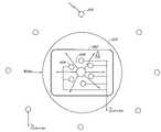
- FIG. 1shows a multi-zone sprinkler system.
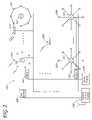
- FIG. 2is a schematic diagram of a multi-zone sprinkler system.
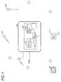
- FIG. 3shows an adjustable-pattern sprinkler head with associated moisture sensors.
- FIG. 4is a block diagram of a rotating sprinkler with controllable rotation rates.
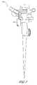
- FIG. 5shows a rotating sprinkler with an actuator to control rotation speed.
- FIG. 6is a schematic diagram of a non-rotating sprinkler head with an adjustable spray pattern.
- FIG. 1illustrates a golf course as one exemplary application for one embodiment of a multi-zone sprinkler system 100 .
- Other exemplary applicationsinclude, but are not limited to, recreational parks, home lawns, theme parks, cemeteries, farms, nurseries, and any other setting that provides water to vegetation through an automatic watering system.
- FIG. 1illustrates a plurality of sprinklers 102 , each having an electronically configurable spray pattern 104 .
- FIG. 2is a schematic diagram of one embodiment of the multi-zone sprinkler system 100 .
- the sprinkler system 100includes the sprinklers 102 , moisture sensors 200 , water supply valves 202 , a water supply 204 , and a central control system 206 .
- a series of water supply valves 202each connect to the water supply 204 .
- Each water supply valve 202connects to a series of sprinklers 102 , each sprinkler 102 having the configurable spray pattern 104 .
- the water from the water supply 204flows through the water supply valve 202 .
- the sprinkler 102waters some, all, or none of the area surrounding the sprinkler 102 .
- the sprinkler system 100is arranged in watering zones.
- the water supplycan include fertilizer, weed control solution, or any other soluble compound the user desires to apply to the area associated with the sprinkler system 100 .
- the multi-zone sprinkler system 100includes at least one water control valve 202 , and at least one sprinkler 102 having a configurable spray pattern 104 .
- the moisture sensors 200are buried in the soil to sense the moisture in the soil. In one embodiment, the moisture sensors 200 form a circular or semi-circular arrangement around each sprinkler 102 .
- the moisture sensors 200transmit data indicating the moisture content of the soil to the central control system 206 . In one embodiment, the moisture sensors 200 transmit data to the central control system via a radio frequency (RF) link, or other wireless transmission system.
- RFradio frequency
- the moisture sensors 200electrically connect to the sprinklers 102 and the sprinklers 102 communicate with the central control system 206 via the wireless transmission system.
- the moisture sensors 200collect the moisture data and transmit the moisture data through the electrical connection to the sprinklers 102 .
- the sprinklers 102transmit the moisture data via the wireless transmission system, such as the RF link, to the central control system 206 .
- the moisture sensors 200electrically connect to the sprinklers 102 and the sprinklers 102 electrically connect to the central control system 206 .
- the moisture sensors 200collect the moisture data and transmit the moisture data through the electrical connection to the sprinklers 102 .
- the sprinklers 102transmit the moisture data through the electrical connection to the central control system 206 .
- the multi-zone sprinkler system 100further includes a zone controller 210 .
- the moisture sensors 200 located in the zone controlled by the zone controller 210transmit the moisture data to the zone controller 210 .
- the zone controller 210transmits the moisture data to the central control system 206 .
- the moisture sensors 102transmit the moisture data via a wireless transmission system, such as, for example, the RF link, to the zone controller 210 .
- the moisture sensors 200electrically connect to the zone controller 210 .
- Each moisture sensor 200can be individually wired to the zone controller 210 , or groups of moisture sensors 200 can be wired in a consecutive pattern, i.e., daisy chained, and the last moisture sensor 200 in the chain electrically connects to the zone controller 210 .
- the moisture sensors 200transmit the moisture data to the zone controller 210 through the electrical connection.
- the zone controller 210communicates with the central control system via the wireless transmission system, such as, for example, the RF link, and transmits the moisture data via the wireless transmission system to the central control system 206 .
- the zone controller 210electrically connects to the central control system 206 , and transmits the moisture data to the central control system 206 through the electrical connection.
- the central control system 206decides how much water to put down in each zone.
- the central control system 206activates the water control valves 202 , which permits water from the water supply 204 to flow through the water control valves 202 . Further, based on the moisture data, the central control system 206 configures the electrically configurable spray pattern 104 of the sprinklers 102 .
- the central control system 206includes one or more computers.
- the computersinclude, by way of example, processors, program logic, or other substrate configurations representing data and instructions, which operate as described herein.
- the processorscan include controller circuitry, processor circuitry, processors, general-purpose single-chip or multi-chip microprocessors, digital signal processors, embedded microprocessors, microcontrollers and the like.
- the central control system 206includes information relating to the locations of the sprinklers 200 , the area watered or the maximum spray pattern of each sprinkler 200 , watering zones controlled by each zone controller 210 , and the like.
- the central control system 206processes the moisture data to determine which areas require moisture.
- the central control system 206transmits instructions to configure the spray pattern 104 of the sprinklers 102 , such that the areas requiring moisture are watered, and the areas not requiring moisture are not watered.
- the central control system 206transmits instructions to the zone controller 210 through the wireless transmission system or the electrical connection, as described above.
- the zone controller 210then transmits the instructions to the sprinkler 200 through the wireless transmission system or the electrical connection, as described above.
- the central control system 206transmits instructions directly to the sprinkler 102 through the wireless transmission system or the electrical connection, as described above.
- the multi-zone sprinkler system 100further includes fire sensors 208 .
- the fire sensors 208are, for example, smoke detectors, infrared detectors, ultraviolet (UV) detectors, infrared cameras, temperature sensors, or the like.
- the fire sensors 208transmit fire data to the central control system 206 directly or through the zone controller 210 through the wireless transmission system or an electrical connection, as described above.
- the central control system 206transmits instructions to configure the spray pattern 104 of the sprinklers 102 , as described above, such that the areas requiring moisture are watered.
- FIG. 3is a schematic diagram of a sprinkler system 300 .
- the sprinkler system 300includes the sprinkler 102 having the configurable spray pattern 104 , and the moisture sensors 200 .
- the sprinkler 102includes a sprinkler head 302 , which includes at least one computer 304 .
- the computer 304includes, by way of example, processors, program logic, or other substrate configurations representing data and instructions, which operate as described herein.
- the processorscan include controller circuitry, processor circuitry, processors, general-purpose single-chip or multi-chip microprocessors, digital signal processors, embedded microprocessors, microcontrollers and the like.
- the sprinkler head 302receives water when the water control valve 202 activates.
- the computer 304receives control data and power from a central location, such as the central control system 206 . In another embodiment, the computer 304 receives only power from the central location.
- At least one moisture sensor 200is associated with and electrically connects to the sprinkler head 302 .
- a plurality of moisture sensors 200forms a circular pattern around the sprinkler head 300 .
- the moisture sensors 200transmit the moisture data to the computer 304 .
- the computer 304transmits the moisture data to the central control system 206 and receives instructions to configure the spray pattern 104 from the central control system 206 .
- the computer 304receives the moisture data, processes the moisture data to determine the correct spray pattern 104 , and configures the spray pattern 104 based on the moisture data.
- FIG. 3illustrates the spray patterns 104 partially overlapping.
- the spray patterns 104do not overlap.
- the spray patterns 104overlap, such that the area of the sprinkler system 300 is watered by at least one sprinkler 102 .
- FIG. 4is a schematic diagram of one embodiment of a rotating sprinkler 400 .
- the rotating sprinkler 400rotates in a 360 ⁇ arc, or portions of the 360 ⁇ arc, when water flows through the sprinkler 400 .
- the rate of rotation through various portions of the arcdetermines the quantity of water applied to the area surrounding the sprinkler 400 .
- the sprinkler 400applies more water.
- the sprinkler 400rotates quickly, less water is applied.
- the sprinkler 400includes a sprinkler head 402 .
- the sprinkler head 402includes an actuator 404 , positional information 406 , and a data interface 408 .
- the positional information 406 received through the data interface 408controls the activation of the actuator 404 .
- the actuator 404controls the rate of rotation of the sprinkler head 402 .
- the sprinkler 400would be used in a golf course or other industrial application with rotating sprinklers.
- the sprinkler head 402rotates quickly. In another embodiment, when the actuator 404 is closed or inactive, the sprinkler head 402 rotates slowly.
- the water supply 204through the activated water supply valve 202 , supplies water to the sprinkler 400 .
- the moisture sensor 200sends moisture data 410 to the central control system 206 directly or through the sprinkler 400 via the wireless transmission system or electrical connections, or a combination of the wireless transmission system or the electrical connections.
- the central control system 206Based on the moisture data 410 , the central control system 206 sends positional information 406 through the data interface 408 to the sprinkler 400 via the wireless transmission system or electrical connections, or a combination of the wireless transmission system or the electrical connections. Using the positional information, the sprinkler 400 opens or closes the actuator 404 to control the speed at which the sprinkler head 402 rotates.
- the sprinkler 400uses the computer 302 , determines the positional information 406 based on the moisture data 410 . Using the positional information from the computer 302 , the sprinkler 400 opens or closes the actuator 404 to control the rate of rotation of the sprinkler head 402 .
- FIG. 5is a schematic diagram of one embodiment of the sprinkler 400 comprising the actuator 404 .
- the actuator 404can be, for example, a solenoid, a stepper motor, a switch, a relay, a valve, or the like.
- FIG. 6is a schematic diagram of one embodiment of a non-rotating sprinkler 600 .
- the sprinkler 600includes a sprinkler head 602 .
- the sprinkler head 602includes at least one solenoid 604 having an active state and an inactive state.
- Each solenoid 604controls a port 606 associated with the solenoid 604 .
- the solenoids 604 and their associated ports 606form a ring around the perimeter of the sprinkler head 602 .
- eight solenoidscould be used to control eight zones of a circular patterns around the sprinkler 600 .
- the sprinkler 600would be used in a residential application or other application with non-rotating sprinklers.
- the water supply 204 through the activated water supply valve 202supplies water to the sprinkler 600 .
- the port 606When the port 606 is open, water flows through the port 606 .
- the port 606when the solenoid 604 is active, the port 606 is open. In another embodiment, when the solenoid 604 is active, the port 606 is closed. In another embodiment, when the solenoid 604 is inactive, the port 606 is closed. In a yet further embodiment, when the solenoid 604 is inactive, the port 606 is open.
- the central control system 206Based on the moisture data 410 , the central control system 206 sends state information to the sprinkler 600 to control the state of the solenoids 604 .
- the solenoids 604open the ports 606 as determined by the state information.
- the sprinkler 600waters the area associated with the open ports 606 .
- the sprinkler 600uses the computer 302 , controls the state of the solenoids 604 based on the moisture data 410 .
- the sprinkler 600activates the solenoids 604 to open the ports 606 , which waters the areas associated with the open ports 606 .
Landscapes
- Life Sciences & Earth Sciences (AREA)
- Engineering & Computer Science (AREA)
- Water Supply & Treatment (AREA)
- Environmental Sciences (AREA)
- Soil Sciences (AREA)
- Fire-Extinguishing By Fire Departments, And Fire-Extinguishing Equipment And Control Thereof (AREA)
- Spray Control Apparatus (AREA)
- Fire Alarms (AREA)
- Selective Calling Equipment (AREA)
Abstract
Description
Claims (4)
Priority Applications (13)
| Application Number | Priority Date | Filing Date | Title |
|---|---|---|---|
| US11/152,037US7168632B2 (en) | 2005-06-14 | 2005-06-14 | Multi-zone sprinkler system with moisture sensors and configurable spray pattern |
| EP20060759912EP1890530A1 (en) | 2005-06-14 | 2006-05-16 | Multi-zone sprinkler system with moisture sensors and configurable spray pattern |
| RU2007146263/12ARU2007146263A (en) | 2005-06-14 | 2006-05-16 | MULTI-ZONE SPRINKLER SYSTEM WITH HUMIDITY SENSORS AND VARIABLE JET CONFIGURATION |
| CNA2006800213980ACN101198250A (en) | 2005-06-14 | 2006-05-16 | Multi-zone sprinkler system with humidity sensor and configurable spray pattern |
| JP2008516882AJP2008546521A (en) | 2005-06-14 | 2006-05-16 | Multi-zone watering system with humidity sensor and configurable spray pattern |
| AU2006259863AAU2006259863A1 (en) | 2005-06-14 | 2006-05-16 | Multi-zone sprinkler system with moisture sensors and configurable spray pattern |
| KR1020087000612AKR20080015928A (en) | 2005-06-14 | 2006-05-16 | Multi-zone sprinkler system with moisture sensor and configurable spray pattern |
| PCT/US2006/018878WO2006138009A1 (en) | 2005-06-14 | 2006-05-16 | Multi-zone sprinkler system with moisture sensors and configurable spray pattern |
| CA 2612114CA2612114A1 (en) | 2005-06-14 | 2006-05-16 | Multi-zone sprinkler system with moisture sensors and configurable spray pattern |
| MX2007015501AMX2007015501A (en) | 2005-06-14 | 2006-05-16 | Multi-zone sprinkler system with moisture sensors and configurable spray pattern. |
| US11/620,587US7347384B2 (en) | 2005-06-14 | 2007-01-05 | Multi-zone sprinkler system with moisture sensors and configurable spray pattern |
| US12/051,375US7658336B2 (en) | 2005-06-14 | 2008-03-19 | Multi-zone sprinkler system with moisture sensors and configurable spray pattern |
| IN4551DEN2014IN2014DN04551A (en) | 2005-06-14 | 2014-06-05 |
Applications Claiming Priority (1)
| Application Number | Priority Date | Filing Date | Title |
|---|---|---|---|
| US11/152,037US7168632B2 (en) | 2005-06-14 | 2005-06-14 | Multi-zone sprinkler system with moisture sensors and configurable spray pattern |
Related Child Applications (1)
| Application Number | Title | Priority Date | Filing Date |
|---|---|---|---|
| US11/620,587ContinuationUS7347384B2 (en) | 2005-06-14 | 2007-01-05 | Multi-zone sprinkler system with moisture sensors and configurable spray pattern |
Publications (2)
| Publication Number | Publication Date |
|---|---|
| US20060278728A1 US20060278728A1 (en) | 2006-12-14 |
| US7168632B2true US7168632B2 (en) | 2007-01-30 |
Family
ID=37067518
Family Applications (3)
| Application Number | Title | Priority Date | Filing Date |
|---|---|---|---|
| US11/152,037Expired - LifetimeUS7168632B2 (en) | 2005-06-14 | 2005-06-14 | Multi-zone sprinkler system with moisture sensors and configurable spray pattern |
| US11/620,587Expired - Fee RelatedUS7347384B2 (en) | 2005-06-14 | 2007-01-05 | Multi-zone sprinkler system with moisture sensors and configurable spray pattern |
| US12/051,375Expired - Fee RelatedUS7658336B2 (en) | 2005-06-14 | 2008-03-19 | Multi-zone sprinkler system with moisture sensors and configurable spray pattern |
Family Applications After (2)
| Application Number | Title | Priority Date | Filing Date |
|---|---|---|---|
| US11/620,587Expired - Fee RelatedUS7347384B2 (en) | 2005-06-14 | 2007-01-05 | Multi-zone sprinkler system with moisture sensors and configurable spray pattern |
| US12/051,375Expired - Fee RelatedUS7658336B2 (en) | 2005-06-14 | 2008-03-19 | Multi-zone sprinkler system with moisture sensors and configurable spray pattern |
Country Status (11)
| Country | Link |
|---|---|
| US (3) | US7168632B2 (en) |
| EP (1) | EP1890530A1 (en) |
| JP (1) | JP2008546521A (en) |
| KR (1) | KR20080015928A (en) |
| CN (1) | CN101198250A (en) |
| AU (1) | AU2006259863A1 (en) |
| CA (1) | CA2612114A1 (en) |
| IN (1) | IN2014DN04551A (en) |
| MX (1) | MX2007015501A (en) |
| RU (1) | RU2007146263A (en) |
| WO (1) | WO2006138009A1 (en) |
Cited By (19)
| Publication number | Priority date | Publication date | Assignee | Title |
|---|---|---|---|---|
| US20070102538A1 (en)* | 2005-06-14 | 2007-05-10 | Lawrence Kates | Multi-zone sprinkler system with moisture sensors and configurable spray pattern |
| US20080255708A1 (en)* | 2007-03-14 | 2008-10-16 | Melnor, Inc. | Smart water timer |
| US20090150003A1 (en)* | 2007-11-16 | 2009-06-11 | Jordan B Delano | Turf Irrigation System |
| US20100012744A1 (en)* | 2008-07-16 | 2010-01-21 | Lawrence Kates | Multi-zone sprinkler system with moisture sensors and adjustable spray pattern |
| US7850094B2 (en) | 2009-01-13 | 2010-12-14 | Rain Bird Corporation | Arc adjustable rotary sprinkler having full-circle operation |
| US20110238228A1 (en)* | 2004-11-09 | 2011-09-29 | Hunter Industries, Inc. | Irrigation System with ET Based Seasonal Watering Adjustment |
| US20110238229A1 (en)* | 2004-11-09 | 2011-09-29 | Hunter Industries, Inc. | Irrigation System with Soil Moisture Based Seasonal Watering Adjustment |
| US8606415B1 (en) | 2011-01-06 | 2013-12-10 | Hunter Industries, Inc. | Irrigation system with ET based seasonal watering adjustment and soil moisture sensor shutoff |
| US8793024B1 (en)* | 2009-02-27 | 2014-07-29 | Hunter Industries, Inc. | Irrigation system with multiple soil moisture based seasonal watering adjustment |
| US9120111B2 (en) | 2012-02-24 | 2015-09-01 | Rain Bird Corporation | Arc adjustable rotary sprinkler having full-circle operation and automatic matched precipitation |
| US9156043B2 (en) | 2012-07-13 | 2015-10-13 | Rain Bird Corporation | Arc adjustable rotary sprinkler with automatic matched precipitation |
| US9301461B2 (en) | 2004-11-09 | 2016-04-05 | Hunter Industries, Inc. | Systems and methods to adjust irrigation |
| US20180125057A1 (en)* | 2017-09-29 | 2018-05-10 | Yu-Chen Liu | Multifunction infrared induction water sprinkler |
| US10989427B2 (en) | 2017-12-20 | 2021-04-27 | Trane International Inc. | HVAC system including smart diagnostic capabilites |
| US11933417B2 (en) | 2019-09-27 | 2024-03-19 | Rain Bird Corporation | Irrigation sprinkler service valve |
| US12030072B2 (en) | 2020-11-16 | 2024-07-09 | Rain Bird Corporation | Pressure regulation device and method for irrigation sprinklers |
| US12343748B2 (en) | 2021-03-16 | 2025-07-01 | Rain Bird Corporation | Multi-mode rotor sprinkler apparatus and method |
| US12434252B2 (en) | 2022-04-20 | 2025-10-07 | Rain Bird Corporation | Full-circle and part-circle rotor sprinkler |
| US12440855B2 (en) | 2022-10-27 | 2025-10-14 | Rain Bird Corporation | Multi-mode rotor sprinkler apparatus and method |
Families Citing this family (30)
| Publication number | Priority date | Publication date | Assignee | Title |
|---|---|---|---|---|
| US20080251602A1 (en)* | 2006-10-10 | 2008-10-16 | Curtis Stephen Leggett | Wireless Irrigation and Trespasser Deterrent Control System (WITDCS) |
| US7805221B2 (en)* | 2007-05-17 | 2010-09-28 | Rain Bird Corporation | Automatically adjusting irrigation controller |
| US8200368B2 (en) | 2008-12-10 | 2012-06-12 | Rain Bird Corporation | Automatically adjusting irrigation controller with temperature and rainfall sensor |
| US20100118148A1 (en)* | 2008-11-11 | 2010-05-13 | Young Hwan Lee | Illumination Apparatus |
| US8225810B2 (en)* | 2008-12-12 | 2012-07-24 | Blanchard Rod N | Irrigation control apparatus, system, and method |
| MY151175A (en)* | 2009-01-22 | 2014-04-30 | Mimos Berhad | A device for controlling and profiling field conditions and a method therefor |
| US20100200673A1 (en)* | 2009-02-09 | 2010-08-12 | Everett Gregory J | Configurable sprinkler head and irrigation system, and methods of constructing and utilizing same |
| US20100200674A1 (en)* | 2009-02-09 | 2010-08-12 | Everett Gregory J | Configurable sprinkler system with optional wireless data transfer, and methods of constructing and utilizing same |
| US7946613B2 (en)* | 2009-03-03 | 2011-05-24 | Autoliv Asp, Inc. | Dual chamber airbag cushion |
| JP5021783B2 (en)* | 2010-03-31 | 2012-09-12 | 株式会社アクティオ | Spraying apparatus and spraying method |
| US9872445B2 (en)* | 2010-09-30 | 2018-01-23 | The Toro Company | Turf management |
| CN101972721B (en)* | 2010-11-16 | 2012-08-29 | 武汉大学 | Controllable spraying device |
| WO2012092016A1 (en) | 2010-12-30 | 2012-07-05 | St. Jude Medical, Atrial Fibrillation Division, Inc. | System and method for diagnosing arrhythmias and directing catheter therapies |
| WO2012116299A1 (en)* | 2011-02-24 | 2012-08-30 | Bela Jancsik | Humidity telemetry in processing of materials |
| MX344119B (en)* | 2011-05-27 | 2016-12-06 | Victaulic Co Of America | X-brace valve and flexible connection for fire sprinklers. |
| CN103026947A (en)* | 2012-12-27 | 2013-04-10 | 苏州久三智能科技有限公司 | Automatic sprinkling device for lawn |
| CN103506237B (en)* | 2013-10-11 | 2015-12-02 | 江苏大学 | A kind of square sprays the method for arranging of territory shower nozzle |
| CN104597851A (en)* | 2013-10-30 | 2015-05-06 | 江南大学 | Intelligent orchard environment adjustment and control system |
| US9739711B2 (en)* | 2014-03-26 | 2017-08-22 | The United States Of America As Represented By The Secretary Of The Navy | Controlled rain and fog testing apparatus |
| US9739712B2 (en) | 2014-03-26 | 2017-08-22 | The United States Of America As Represented By The Secretary Of The Navy | Controlled rain and fog testing apparatus |
| US10206341B2 (en) | 2014-07-21 | 2019-02-19 | Rain Bird Corporation | Rainfall prediction and compensation in irrigation control |
| US10512227B2 (en) | 2014-08-08 | 2019-12-24 | H2O Flow Pro, Llc | Water flow management systems and methods |
| CN104920171A (en)* | 2015-06-03 | 2015-09-23 | 广东千森园林科技股份有限公司 | Garden spraying control system |
| US10055781B2 (en) | 2015-06-05 | 2018-08-21 | Boveda Inc. | Systems, methods and devices for controlling humidity in a closed environment with automatic and predictive identification, purchase and replacement of optimal humidity controller |
| US10909607B2 (en) | 2015-06-05 | 2021-02-02 | Boveda Inc. | Systems, methods and devices for controlling humidity in a closed environment with automatic and predictive identification, purchase and replacement of optimal humidity controller |
| CN105013122A (en)* | 2015-07-10 | 2015-11-04 | 常州市南飞机械有限公司 | Fire self-spraying control system and self-spraying method |
| CN105123090A (en)* | 2015-07-16 | 2015-12-09 | 张萍 | Multifunctional intelligent mower based on internet of things |
| CN106873682A (en)* | 2017-04-05 | 2017-06-20 | 合肥德仁智能科技有限公司 | One kind automation plantation control system |
| FR3078607B1 (en)* | 2018-03-08 | 2020-03-27 | Liebearth Sas | ACTIVE AND INTELLIGENT WATERING SYSTEM |
| US11549707B2 (en)* | 2019-12-17 | 2023-01-10 | Carrier Corporation | Method and a system for controlling temperature in different zones of a premises |
Citations (9)
| Publication number | Priority date | Publication date | Assignee | Title |
|---|---|---|---|---|
| US4852802A (en) | 1988-08-08 | 1989-08-01 | Jerry Iggulden | Smart irrigation sprinklers |
| US4892113A (en) | 1986-02-03 | 1990-01-09 | Spectrum 2000, Inc. | Moisture monitor and control system |
| US4993640A (en)* | 1989-06-12 | 1991-02-19 | Baugh Mark R | Fluid control system |
| US5348227A (en) | 1993-04-20 | 1994-09-20 | Eli Polonsky | Irrigation system having ground moisture responsive control jar valve regulation |
| US5465904A (en)* | 1993-12-03 | 1995-11-14 | Vaello; Donald B. | Domestic watering and agricultural irrigation control system |
| US20040026529A1 (en)* | 2002-07-17 | 2004-02-12 | Float Ardele Y. | Landscape sprinkling systems |
| US20050090936A1 (en) | 2003-10-24 | 2005-04-28 | Hitt Dale K. | Two-wire control of sprinkler system |
| US20050187665A1 (en)* | 2004-02-23 | 2005-08-25 | International Business Machines Corporation | Automatic yard moisture control system |
| US20050199842A1 (en)* | 2002-06-24 | 2005-09-15 | Parsons Natan E. | Automated water delivery systems with feedback control |
Family Cites Families (9)
| Publication number | Priority date | Publication date | Assignee | Title |
|---|---|---|---|---|
| JPS5927630B2 (en)* | 1978-07-26 | 1984-07-06 | 松下電工株式会社 | automatic watering device |
| JPH03206822A (en)* | 1990-01-09 | 1991-09-10 | Kajima Corp | Water sprinkler for lawn |
| JPH0423925A (en)* | 1990-05-21 | 1992-01-28 | Marantz Japan Inc | Golf links-watching and controlling system |
| JPH0725234Y2 (en)* | 1991-02-06 | 1995-06-07 | 財団法人鉄道総合技術研究所 | sprinkler |
| JPH09248493A (en)* | 1996-03-14 | 1997-09-22 | Central Japan Railway Co | sprinkler |
| JPH1147642A (en)* | 1997-07-31 | 1999-02-23 | Eiwa Sprinkler:Kk | Liquid scattering method and liquid scattering device |
| CN2321236Y (en)* | 1998-01-06 | 1999-06-02 | 红河卷烟厂 | Novel online redrying sheet tobacco insect prevention liquid medicine spraying equipment |
| JP2002233255A (en)* | 2001-02-07 | 2002-08-20 | Sekisui Plant Systems Co Ltd | Watering system |
| US7168632B2 (en) | 2005-06-14 | 2007-01-30 | Lawrence Kates | Multi-zone sprinkler system with moisture sensors and configurable spray pattern |
- 2005
- 2005-06-14USUS11/152,037patent/US7168632B2/ennot_activeExpired - Lifetime
- 2006
- 2006-05-16JPJP2008516882Apatent/JP2008546521A/enactivePending
- 2006-05-16KRKR1020087000612Apatent/KR20080015928A/ennot_activeCeased
- 2006-05-16WOPCT/US2006/018878patent/WO2006138009A1/enactiveApplication Filing
- 2006-05-16AUAU2006259863Apatent/AU2006259863A1/ennot_activeAbandoned
- 2006-05-16MXMX2007015501Apatent/MX2007015501A/ennot_activeApplication Discontinuation
- 2006-05-16CNCNA2006800213980Apatent/CN101198250A/enactivePending
- 2006-05-16EPEP20060759912patent/EP1890530A1/ennot_activeWithdrawn
- 2006-05-16RURU2007146263/12Apatent/RU2007146263A/ennot_activeApplication Discontinuation
- 2006-05-16CACA 2612114patent/CA2612114A1/ennot_activeAbandoned
- 2007
- 2007-01-05USUS11/620,587patent/US7347384B2/ennot_activeExpired - Fee Related
- 2008
- 2008-03-19USUS12/051,375patent/US7658336B2/ennot_activeExpired - Fee Related
- 2014
- 2014-06-05ININ4551DEN2014patent/IN2014DN04551A/enunknown
Patent Citations (9)
| Publication number | Priority date | Publication date | Assignee | Title |
|---|---|---|---|---|
| US4892113A (en) | 1986-02-03 | 1990-01-09 | Spectrum 2000, Inc. | Moisture monitor and control system |
| US4852802A (en) | 1988-08-08 | 1989-08-01 | Jerry Iggulden | Smart irrigation sprinklers |
| US4993640A (en)* | 1989-06-12 | 1991-02-19 | Baugh Mark R | Fluid control system |
| US5348227A (en) | 1993-04-20 | 1994-09-20 | Eli Polonsky | Irrigation system having ground moisture responsive control jar valve regulation |
| US5465904A (en)* | 1993-12-03 | 1995-11-14 | Vaello; Donald B. | Domestic watering and agricultural irrigation control system |
| US20050199842A1 (en)* | 2002-06-24 | 2005-09-15 | Parsons Natan E. | Automated water delivery systems with feedback control |
| US20040026529A1 (en)* | 2002-07-17 | 2004-02-12 | Float Ardele Y. | Landscape sprinkling systems |
| US20050090936A1 (en) | 2003-10-24 | 2005-04-28 | Hitt Dale K. | Two-wire control of sprinkler system |
| US20050187665A1 (en)* | 2004-02-23 | 2005-08-25 | International Business Machines Corporation | Automatic yard moisture control system |
Cited By (30)
| Publication number | Priority date | Publication date | Assignee | Title |
|---|---|---|---|---|
| US20110238228A1 (en)* | 2004-11-09 | 2011-09-29 | Hunter Industries, Inc. | Irrigation System with ET Based Seasonal Watering Adjustment |
| US9301461B2 (en) | 2004-11-09 | 2016-04-05 | Hunter Industries, Inc. | Systems and methods to adjust irrigation |
| US8660705B2 (en) | 2004-11-09 | 2014-02-25 | Hunter Industries, Inc. | Irrigation system with soil moisture based seasonal watering adjustment |
| US8600569B2 (en) | 2004-11-09 | 2013-12-03 | Hunter Industries, Inc. | Irrigation system with ET based seasonal watering adjustment |
| US20110238229A1 (en)* | 2004-11-09 | 2011-09-29 | Hunter Industries, Inc. | Irrigation System with Soil Moisture Based Seasonal Watering Adjustment |
| US7347384B2 (en) | 2005-06-14 | 2008-03-25 | Lawrence Kates | Multi-zone sprinkler system with moisture sensors and configurable spray pattern |
| US20080223950A1 (en)* | 2005-06-14 | 2008-09-18 | Lawrence Kates | Multi-zone sprinkler system with moisture sensors and configurable spray pattern |
| US7658336B2 (en) | 2005-06-14 | 2010-02-09 | Lawrence Kates | Multi-zone sprinkler system with moisture sensors and configurable spray pattern |
| US20070102538A1 (en)* | 2005-06-14 | 2007-05-10 | Lawrence Kates | Multi-zone sprinkler system with moisture sensors and configurable spray pattern |
| US7810515B2 (en)* | 2007-03-14 | 2010-10-12 | Melnor, Inc. | Smart water timer |
| US20080255708A1 (en)* | 2007-03-14 | 2008-10-16 | Melnor, Inc. | Smart water timer |
| US7913653B2 (en) | 2007-11-16 | 2011-03-29 | Benivoli, LLC | Monitoring system |
| US20090150003A1 (en)* | 2007-11-16 | 2009-06-11 | Jordan B Delano | Turf Irrigation System |
| US20100012744A1 (en)* | 2008-07-16 | 2010-01-21 | Lawrence Kates | Multi-zone sprinkler system with moisture sensors and adjustable spray pattern |
| US7850094B2 (en) | 2009-01-13 | 2010-12-14 | Rain Bird Corporation | Arc adjustable rotary sprinkler having full-circle operation |
| US8793024B1 (en)* | 2009-02-27 | 2014-07-29 | Hunter Industries, Inc. | Irrigation system with multiple soil moisture based seasonal watering adjustment |
| US9781887B2 (en) | 2011-01-06 | 2017-10-10 | Hunter Industries, Inc. | Irrigation system with ET based seasonal watering adjustment and soil moisture sensor shutoff |
| US8924032B2 (en) | 2011-01-06 | 2014-12-30 | Hunter Industries, Inc. | Irrigation system with ET based seasonal watering adjustment and soil moisture sensor shutoff |
| US8606415B1 (en) | 2011-01-06 | 2013-12-10 | Hunter Industries, Inc. | Irrigation system with ET based seasonal watering adjustment and soil moisture sensor shutoff |
| US9120111B2 (en) | 2012-02-24 | 2015-09-01 | Rain Bird Corporation | Arc adjustable rotary sprinkler having full-circle operation and automatic matched precipitation |
| US9156043B2 (en) | 2012-07-13 | 2015-10-13 | Rain Bird Corporation | Arc adjustable rotary sprinkler with automatic matched precipitation |
| US11172671B2 (en)* | 2017-09-29 | 2021-11-16 | Handle Tech (Sz) Co., Ltd. | Multifunction infrared induction water sprinkler |
| US20180125057A1 (en)* | 2017-09-29 | 2018-05-10 | Yu-Chen Liu | Multifunction infrared induction water sprinkler |
| US10989427B2 (en) | 2017-12-20 | 2021-04-27 | Trane International Inc. | HVAC system including smart diagnostic capabilites |
| US11708982B2 (en) | 2017-12-20 | 2023-07-25 | Trane International Inc. | HVAC system including smart diagnostic capabilities |
| US11933417B2 (en) | 2019-09-27 | 2024-03-19 | Rain Bird Corporation | Irrigation sprinkler service valve |
| US12030072B2 (en) | 2020-11-16 | 2024-07-09 | Rain Bird Corporation | Pressure regulation device and method for irrigation sprinklers |
| US12343748B2 (en) | 2021-03-16 | 2025-07-01 | Rain Bird Corporation | Multi-mode rotor sprinkler apparatus and method |
| US12434252B2 (en) | 2022-04-20 | 2025-10-07 | Rain Bird Corporation | Full-circle and part-circle rotor sprinkler |
| US12440855B2 (en) | 2022-10-27 | 2025-10-14 | Rain Bird Corporation | Multi-mode rotor sprinkler apparatus and method |
Also Published As
| Publication number | Publication date |
|---|---|
| RU2007146263A (en) | 2009-07-20 |
| US7347384B2 (en) | 2008-03-25 |
| US20060278728A1 (en) | 2006-12-14 |
| EP1890530A1 (en) | 2008-02-27 |
| JP2008546521A (en) | 2008-12-25 |
| CN101198250A (en) | 2008-06-11 |
| US7658336B2 (en) | 2010-02-09 |
| CA2612114A1 (en) | 2006-12-28 |
| WO2006138009A1 (en) | 2006-12-28 |
| MX2007015501A (en) | 2008-02-22 |
| US20080223950A1 (en) | 2008-09-18 |
| KR20080015928A (en) | 2008-02-20 |
| IN2014DN04551A (en) | 2015-07-10 |
| US20070102538A1 (en) | 2007-05-10 |
| AU2006259863A1 (en) | 2006-12-28 |
Similar Documents
| Publication | Publication Date | Title |
|---|---|---|
| US7168632B2 (en) | Multi-zone sprinkler system with moisture sensors and configurable spray pattern | |
| US20100012744A1 (en) | Multi-zone sprinkler system with moisture sensors and adjustable spray pattern | |
| US5246164A (en) | Method and apparatus for variable application of irrigation water and chemicals | |
| US6947811B2 (en) | Automatic adjustment of irrigation schedule according to condition of plants | |
| US20060157580A1 (en) | System and method for controlling irrigation | |
| US6267298B1 (en) | Neural networked irrigation controller | |
| CA2944795C (en) | Sprinkler apparatus and system for irrigation | |
| AU5187801A (en) | Method and means for controlling the functions of an irrigation system and ancillary equipment | |
| Sadler et al. | A site‐specific center pivot irrigation system for highly‐variable coastal plain soils | |
| US20050135880A1 (en) | Root zone injection surface irrigation system | |
| CN205455082U (en) | Horticulture irrigation equipment | |
| Chen et al. | Innovative technologies in sprinkler irrigation: An overview | |
| Sadler et al. | Venturing into precision agriculture | |
| CN118020617B (en) | Smart Agriculture Remote Controlled Automatic Irrigation System | |
| CA2179502A1 (en) | Variable application of irrigation water and chemicals | |
| KR200234636Y1 (en) | Device for management plant of artificial the ground | |
| Trout et al. | On‐farm system design and operation and land management | |
| AU689444B2 (en) | Method and apparatus for variable application of irrigation water and chemicals | |
| WO2022219415A1 (en) | Intelligent climate control system for greenhouses | |
| JPH0352127Y2 (en) | ||
| Abraham | Chapter-2 Irrigation Types and Systems | |
| Sadler et al. | CoNTROLS FOR PRECIsIoN IRRIGATION wTH sELF-PRoPELLED sysTEMs | |
| Kincaid et al. | Irrigation, site-specific | |
| JPH0739251A (en) | How to grow halophytes | |
| Almusaed | Introduction on irrigation systems |
Legal Events
| Date | Code | Title | Description |
|---|---|---|---|
| STCF | Information on status: patent grant | Free format text:PATENTED CASE | |
| AS | Assignment | Owner name:KNOBBE, MARTENS, OLSON & BEAR, LLP, CALIFORNIA Free format text:SECURITY INTEREST;ASSIGNOR:KATES, LAWRENCE;REEL/FRAME:022460/0472 Effective date:20090121 Owner name:KNOBBE, MARTENS, OLSON & BEAR, LLP,CALIFORNIA Free format text:SECURITY INTEREST;ASSIGNOR:KATES, LAWRENCE;REEL/FRAME:022460/0472 Effective date:20090121 | |
| FEPP | Fee payment procedure | Free format text:PAYOR NUMBER ASSIGNED (ORIGINAL EVENT CODE: ASPN); ENTITY STATUS OF PATENT OWNER: LARGE ENTITY Free format text:PAYER NUMBER DE-ASSIGNED (ORIGINAL EVENT CODE: RMPN); ENTITY STATUS OF PATENT OWNER: LARGE ENTITY | |
| FPAY | Fee payment | Year of fee payment:4 | |
| AS | Assignment | Owner name:NEST LABS, INC., CALIFORNIA Free format text:ASSIGNMENT OF ASSIGNORS INTEREST;ASSIGNOR:KATES, LAWRENCE;REEL/FRAME:031658/0179 Effective date:20130927 Owner name:NEST LABS, INC., CALIFORNIA Free format text:RELEASE BY SECURED PARTY;ASSIGNOR:KNOBBE, MARTENS, OLSON & BEAR LLP;REEL/FRAME:031658/0093 Effective date:20130927 | |
| FEPP | Fee payment procedure | Free format text:PAT HOLDER NO LONGER CLAIMS SMALL ENTITY STATUS, ENTITY STATUS SET TO UNDISCOUNTED (ORIGINAL EVENT CODE: STOL); ENTITY STATUS OF PATENT OWNER: LARGE ENTITY | |
| FPAY | Fee payment | Year of fee payment:8 | |
| AS | Assignment | Owner name:NEST LABS, INC., CALIFORNIA Free format text:CORRECTIVE ASSIGNMENT TO CORRECT THE INADVERTENT ADDITION OF U.S.PATENT NO. 8,101,892 TO THE LIST. ALL OTHER NUMBERS REMAIN AS PREVIOUSLY RECORDED ON REEL 031658 FRAME 0093. ASSIGNOR(S) HEREBY CONFIRMS THE U.S. PATENT NO. 8,101,892 IS TO BE REMOVED;ASSIGNOR:KNOBBE, MARTENS, OLSON & BEAR LLP;REEL/FRAME:033429/0848 Effective date:20130927 | |
| AS | Assignment | Owner name:NEST LABS, INC., CALIFORNIA Free format text:CORRECTIVE ASSIGNMENT TO CORRECT THE INADVERTENT PATENT NO. 8,101,892 TO BE REMOVED PREVIOUSLY RECORDED AT REEL: 031658 FRAME: 0179. ASSIGNOR(S) HEREBY CONFIRMS THE ASSIGNMENT;ASSIGNOR:KATES, LAWRENCE;REEL/FRAME:033452/0413 Effective date:20130927 | |
| AS | Assignment | Owner name:GOOGLE INC., CALIFORNIA Free format text:ASSIGNMENT OF ASSIGNORS INTEREST;ASSIGNOR:NEST LABS, INC.;REEL/FRAME:033568/0693 Effective date:20140207 | |
| AS | Assignment | Owner name:GOOGLE LLC, CALIFORNIA Free format text:CHANGE OF NAME;ASSIGNOR:GOOGLE INC.;REEL/FRAME:044127/0735 Effective date:20170929 | |
| MAFP | Maintenance fee payment | Free format text:PAYMENT OF MAINTENANCE FEE, 12TH YEAR, LARGE ENTITY (ORIGINAL EVENT CODE: M1553) Year of fee payment:12 |