US7168334B1 - Arrangement for measuring a property of a fluid present in a tube - Google Patents
Arrangement for measuring a property of a fluid present in a tubeDownload PDFInfo
- Publication number
- US7168334B1 US7168334B1US09/980,066US98006602AUS7168334B1US 7168334 B1US7168334 B1US 7168334B1US 98006602 AUS98006602 AUS 98006602AUS 7168334 B1US7168334 B1US 7168334B1
- Authority
- US
- United States
- Prior art keywords
- tube
- sensor
- access opening
- lateral access
- sealing surface
- Prior art date
- Legal status (The legal status is an assumption and is not a legal conclusion. Google has not performed a legal analysis and makes no representation as to the accuracy of the status listed.)
- Expired - Fee Related
Links
- 239000012530fluidSubstances0.000titleabstractdescription60
- 238000007789sealingMethods0.000claimsabstractdescription28
- 238000000502dialysisMethods0.000claimsdescription6
- 239000011521glassSubstances0.000claimsdescription6
- 239000000463materialSubstances0.000claimsdescription6
- 239000002184metalSubstances0.000claimsdescription5
- 239000004033plasticSubstances0.000claimsdescription4
- 239000007788liquidSubstances0.000claims9
- 238000005259measurementMethods0.000description6
- 238000004519manufacturing processMethods0.000description4
- 230000015572biosynthetic processEffects0.000description3
- 230000002349favourable effectEffects0.000description3
- 238000009434installationMethods0.000description3
- 230000007704transitionEffects0.000description3
- 239000000853adhesiveSubstances0.000description2
- 230000001070adhesive effectEffects0.000description2
- 230000008859changeEffects0.000description2
- 239000013013elastic materialSubstances0.000description2
- 241000894006BacteriaSpecies0.000description1
- 238000004026adhesive bondingMethods0.000description1
- 244000052616bacterial pathogenSpecies0.000description1
- 238000005452bendingMethods0.000description1
- 230000008901benefitEffects0.000description1
- 230000000903blocking effectEffects0.000description1
- 238000009395breedingMethods0.000description1
- 230000001488breeding effectEffects0.000description1
- 230000007423decreaseEffects0.000description1
- 239000000385dialysis solutionSubstances0.000description1
- 230000000694effectsEffects0.000description1
- 238000011156evaluationMethods0.000description1
- 238000000034methodMethods0.000description1
- 239000000203mixtureSubstances0.000description1
- 238000012986modificationMethods0.000description1
- 230000004048modificationEffects0.000description1
- 230000008569processEffects0.000description1
- 230000000717retained effectEffects0.000description1
- 229920002994synthetic fiberPolymers0.000description1
Images
Classifications
- G—PHYSICS
- G01—MEASURING; TESTING
- G01N—INVESTIGATING OR ANALYSING MATERIALS BY DETERMINING THEIR CHEMICAL OR PHYSICAL PROPERTIES
- G01N33/00—Investigating or analysing materials by specific methods not covered by groups G01N1/00 - G01N31/00
- G01N33/48—Biological material, e.g. blood, urine; Haemocytometers
- G01N33/483—Physical analysis of biological material
- G01N33/487—Physical analysis of biological material of liquid biological material
Definitions
- the present inventionrelates to apparatus for measuring a property of a fluid present in a tube, with a sensor for measuring the desired property, which sensor is disposed on the tube and is in direct contact with the fluid through a lateral access opening.
- apparatus for measuring a property of a fluid present in a tubeare known. They are utilized in the most diverse apparatus, for example in dialysis monitors, for measuring any properties of the fluid. To this end, they generally comprise a sensor, which is suitable for measuring the desired property.
- the measured properties of the fluidare, for instance, the temperature, the flow velocity, the pressure, the conductivity, etc.
- the senoris in direct contact with the fluid, which is generally established through a lateral access opening, i.e. a lateral opening in the tube.
- the sensoris arranged on the tube in such a way that it protrudes at least partially into the tube through the lateral access opening, and is thus in direct contact with the fluid which flows substantially completely around it.
- temperature sensorsfor example, which must be substantially entirely surrounded by the fluid, or which have the fluid flow substantially entirely around them, in order to record an exact temperature.
- the sensormay also be disposed on the tube such that it protrudes only into the lateral access opening, but not into the tube itself, so that it is in contact with the fluid, but the fluid does not flow completely around it, or is not entirely surrounded by fluid. This is adequate, for example, for sensors with electrodes for measuring the inductance of the fluid.
- the tubeowing to the geometry of the tube it is difficult to provide a lateral access opening that, on the one hand, allows for direct contact of the sensor with the fluid and, on the other hand, is reliably sealed from the surroundings. Apart from the requisite direct contact with the fluid, the sensor disposed on the tube also needs a connection to an evaluating unit or the like, in order to relay the measured values.
- German Patent Publication No. 35 08 570suggests, for example, inserting a shut-off valve with a plug in a tube, the plug comprising a bore in the axis of rotation.
- a sensoris inserted in the bore and sealed with a sealing ring. Then, when for example as a result of the composition of the fluid, deposits build up with time on the sensor that is in direct contact with the fluid and impede the exact measurement of the required measured value, it is possible to replace the sensor without difficulty.
- the shut-off valveis set in its blocking position so that the fluid flow is interrupted and the sensor can be replaced without loss of fluid.
- a disadvantage of this type of apparatusis that the tube must be completely severed during installation of the shut-off valve. Thus, after successful installation of the shut-off valve, additional seal surfaces with additional possible unsealed areas are created. Moreover, a shut-off valve entails an additional material expense in addition to the supplementary installation expense, thus creating additional costs.
- German Patent Publication No. 41 01 549for measuring temperatures in tubes, in which a bushing is welded laterally to a tube and forms a lateral access opening. A plug having a central bore is inserted in the bushing. Furthermore, a temperature sensor is screwed into the bushing and is pushed through the bore of the plug to the fluid, and protrudes into the fluid. The plug, which seals the temperature sensor from the fluid, is specifically worked on the side directed towards the fluid. This is intended to prevent the formation of gaps between the plug and the tube wall as breeding grounds for bacteria and other germs.
- An apparatus for measuring the temperature of a fluid present in a tubeis known from European Patent No. 413,198, in which a bushing is similarly welded laterally to a tube and forms a lateral access opening to the fluid. An extensively worked ball valve is screwed into the bushing. A temperature sensor is pushed through the ball valve in the latter's open position up to the fluid in the tube, and is sealed against the fluid by ring seals before the ball valve and after the ball valve. In this way it is possible to replace the temperature sensor without shutting off the fluid.
- numerous seal surfacesare necessary, which increases the risk of leaks.
- this known apparatusis also expensive in terms of material and labor and is therefore costly.
- a tube for retaining the fluidcomprising a tube for retaining the fluid, the tube including an outer wall, a lateral access opening, and a domed portion including a sealing surface on the outside wall of the tube surrounding the lateral access opening, and a sensor sealingly disposed on the sealing surface surrounding the lateral access opening in the tube for direct contact with the fluid in the tube for sensing the property of the fluid in the tube.
- the sealing surfacecomprises a level surface.
- the domed portion of the tubecomprises a bend in the entire tube.
- the domed portion of the tubecomprises an outward bulge on one side of the tube.
- the sealing surfacecomprises the wall of the tube.
- the apparatusincludes adhering means for adhering the sensor to the sealing surface.
- the senoris a temperature sensor, a pressure sensor, a flow meter, and/or a conductivity sensor.
- the apparatusincludes a leveled-off planar portion of the wall of the tube on the outer side of the domed portion thereby providing the lateral access opening.
- the leveled-off planar portion of the wallcomprises a ground-off portion thereof.
- the tubeis elastic, flexible, or rigid.
- the rigid tubeis made from metal, plastic and glass.
- a dialysis monitorincluding apparatus for measuring a property of a fluid as set forth above.
- the above objectsare achieved with apparatus of the type discussed above in which the tube includes a domed wall portion, the domed wall portion includes a seal surface on its outer side, the lateral access opening is formed in the seal surface, and the sensor is disposed in a sealed manner on the seal surface over the lateral access opening.
- a simple apparatuswhich for example may be used in dialysis monitors, which enables a simple and at the same time reliable seal of the lateral access opening on the tube.
- a large seal surfaceis provided that is formed substantially without edges and corners, on which the sensor can be simply disposed in a reliably sealed manner.
- the sensoris arranged over the lateral access opening, which is arranged in such a way in the seal surface, or which terminates in such a way in the seal surface, that it is surrounded by the seal surface.
- the lateral access openingis simply and reliably sealed by the sensor itself and, on the other hand, the sensor is readily brought into direct contact with the fluid. The sensor thus sits on the seal surface and is simultaneously in direct contact with the fluid.
- a domed wall portionBy forming a domed wall portion and arranging a seal surface on the outer side thereof, there is in particular provided a larger seal surface that comprises no edges or corners and on which the sensor can sit.
- the apparatus known from the prior art having a lateral access opening in the tubegenerally include lateral seal surfaces having edges, corners or gaps. The sensor lies laterally against these seal surfaces, which renders a reliable seal difficult. This problem is removed by the present invention.
- the seal surfaceis a level surface
- a further improved seal of the lateral access openingis made possible.
- a reliable sealcan be obtained more easily on a level surface, and the sensor can simply be placed on the seal surface so that it covers the lateral access opening.
- an appropriate sealis provided between sensor and seal surface, for example a sealing ring or even adhesion between sensor and seal surface, as provided in accordance with another preferred embodiment, the lateral access opening is then reliably sealed by the sensor itself.
- the domed wall portion of the tubecan be formed in any manner.
- the whole tubecan be bent to form the domed wall surface, as is provided according to a preferred embodiment.
- the wall of the tubecan be distended with a bulge on one side to form the domed wall portion, which is provided according to another preferred embodiment.
- the lateral access to the interior of the tube arranged in the seal surfacecan be formed in any manner. However, it is advantageous, and provided according to a preferred embodiment, when the lateral access opening is formed by levelling away the wall of the tube at the outer side of the domed wall portion along a flat plane. In doing this it is advantageous when the domed wall portion is ground away at its outer side to form the lateral access opening. In this manner, the seal surface will simultaneously be formed with the lateral access so that the manufacture is further simplified and the arrangement becomes altogether less expensive. Moreover, in this manner, a transition between the lateral access opening and the interior of the tube is provided that is favorable to flow, which is of particular advantage when the fluid present in the tube flows.
- the lateral access openingcan be formed in the manner described above both with an elastic and/or flexible tube, or also with a rigid tube.
- This apparatusis, however, particularly advantageous with a rigid tube, that for example can consist of metal, synthetic material or even glass. Particularly in the case of glass the sealing of a lateral access opening was previously difficult and coupled with problems, which are now removed by the present invention.
- any sensorscan be used in the arrangement, such as for example temperature sensors, pressure sensors, flow meters or even conductivity sensors.
- the apparatuscan be employed in diverse apparatus, such as in dialysis monitors.
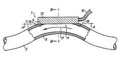
- FIG. 1is a side, elevational, partially sectional view of one embodiment of the apparatus of the present invention
- FIG. 2is a front, elevational, cross-sectional view, taken along line B—B in FIG. 1 ;
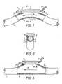
- FIG. 3is a side, elevational, partially sectional view of another embodiment of the apparatus of the present invention.
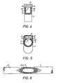
- FIG. 4is a front, elevational, cross-sectional view of yet another embodiment of the apparatus of the present invention.
- FIG. 5is a front, elevational, cross-sectional view of yet another embodiment of the apparatus of the present invention.
- FIG. 6is a top, elevational view taken along line A—A in FIG. 1 and FIG. 3 .
- FIG. 1shows a first embodiment of the measurement apparatus 1 in longitudinal section.
- the measurement apparatus 1includes a sensor 13 that is disposed on a tube 3 to measure properties of a fluid 17 present in the tube 3 .
- the fluid 17can be either stationary in the tube or flow through it.
- the tube 3comprises a domed wall portion 7 that, in this embodiment, is formed by bending the whole tube 3 .
- a seal surface 9On its outer side the domed wall portion 7 there is a seal surface 9 , in which a lateral access opening 11 is arranged.
- the seal surface 9is formed together with the lateral access opening 11 by grinding away the outer side of the domed wall portion 7 along a flat plane. This plane is indicated by the dashed and dotted line A—A.
- the seal surfaceis thus formed by the ground away portion of the wall 5 of the tube 3 .
- the form of the transition between the lateral access opening 11 and the interior of the tube 3that is very favorable in fluid mechanical terms can be readily seen here, and is particularly advantageous when the fluid flows.
- the sensor 13is arranged on the seal surface 9 in such a manner that it completely covers and thus seals the lateral access opening 11 . Simultaneously, it is in direct contact with the fluid 17 .
- the required seal between sensor 13 and seal surface 9can be achieved in any desired manner.
- the sensor 13is glued on the seal surface 9 by means of a suitable adhesive 19 .
- the tube 3in this case consists of glass but may consist of any other material such as plastic, metal or an elastic material.
- the sensor 13is in direct contact with the fluid 17 present in the tube 3 through the lateral access opening 11 of the tube 3 .
- the sensor 13can directly determine or measure the desired property of the fluid 17 and relay the measured values by means of electrical connections 15 to an evaluation unit or the like, which is not illustrated, where they can then be processed.
- FIG. 2is shown a section along line B—B of FIG. 1 .
- the seal surface 9is formed by the wall 5 of the tube 3 that has been levelled away along a flat plane on the outer side of the domed wall portion 7 .
- the lateral access opening 11 to the interior of the tube 3is formed at the same time as the seal surface 9 , and a transition between the lateral access opening 11 and the interior of the tube 3 is obtained in a fluid-mechanically favorable fashion.
- the sensor 13is arranged on the seal surface 9 above the lateral access opening 11 in such a manner that it completely covers, and therefore seals, the lateral access opening 11 .
- FIG. 3a second embodiment of the measurement apparatus in longitudinal section. Like parts are denoted by like reference numerals.
- the tube 3 ′ of this embodimentis not bent as a whole to form the domed wall portion 7 . Instead, only a region of the wall of the tube 3 ′ bulges outwardly to form the domed wall portion 7 .
- a seal surface 9that is created by levelling away the outer side of the domed wall surface along a straight line A—A is formed on the outer side of the domed wall portion 7 .
- the sensor 13is then, in turn, arranged on the seal surface 9 such that it completely covers, and accordingly seals, the lateral access opening 11 , while being simultaneously in direct contact with the fluid 17 .
- a seal between sensor 13 and seal surface 9is accomplished in this embodiment also by gluing the sensor 13 to the seal surface 9 by means of a suitable adhesive 19 .
- the tube 3 ′is of metal, however the embodiment shown here can also be utilized with tubes of any other material, such as for example glass or plastic, or even elastic materials.
- the senor 13is coupled by electrical connections 15 to an evaluating unit (not shown), or the like, in order to relay and process the values determined by the sensor 13 regarding the property of the fluid 17 present in the tube 3 ′.
- the cross-section of the tube 3 ′expands in the region of the apparatus, while the cross-section of the tube 3 of the first embodiment shown in FIG. 1 narrows in the region of the apparatus.
- the flow velocity of a fluid 17 flowing in the apparatus according to the first embodimentincreases, while the flow velocity of a fluid 17 flowing in the arrangement according to the second embodiment decreases.
- Thiscan influence the property of the fluid 17 to be measured so that, depending on the property of the fluid 17 to be measured, the embodiment that does not, or least, influences the property to be measured is to be selected.
- FIG. 4shows a cross-section through the tube 3 ′′ in a similar fashion to FIG. 2 .
- the tube 3 ′′is rectangular and bent as a whole to form the domed portion 7 in a similar fashion to that shown in FIG. 1 .
- the outer side of the domed portion 7is completely levelled away up to the side walls to form the lateral access opening 11 , such that the sensor 13 placed thereon takes the place of the original outer side. In this way, the original cross-section is retained.
- FIG. 5A further example is shown in FIG. 5 , which likewise shows a cross-section through a tube 3 ′′′ in a similar fashion to FIG. 2 .
- the tube 3 ′′′comprises a circular cross-section and is bent as a whole to form the domed portion 7 , in a similar fashion to that shown in FIG. 1 .
- the outer side of the domed portion 7is levelled away to just such an extent that a small opening is formed in the wall 5 .
- Thisis covered by the sensor 13 placed thereon, the sensor 13 protruding only a little into the tube 3 ′′′. This has the effect that the cross-section of the tube in the region of the measurement apparatus is only slightly, and on the whole negligibly, reduced.
- the senor 13is in this case attached to the seal surface 9 with a holding band 23 .
- the seal between sensor 13 and tube 3 , or seal surface 9 respectively,is obtained with a sealing ring 21 in this embodiment.
- FIG. 6shows a plan view of a section along the line A—A in FIG. 1 and FIG. 3 .
- the lateral access opening 11is arranged in the seal surface 9 such that it is completely surrounded by the seal surface 9 .
- the seal surface 9is formed by the levelling away of wall 5 of the tube 3 , 3 ′ along a flat plane, which enables its simple and inexpensive formation.
- a level seal surfaceis provided that comprises no corners, edges or gaps and thus enables a simple and reliable seal.
- an apparatus for measuring a property of a fluid present in a tubeis provided that is simple and inexpensive to manufacture and simply and inexpensively enables a reliable sealing of the sensor utilized in the apparatus.
- the apparatuscan be employed for any application and for any apparatus, for example also in dialysis monitors. In the latter, the apparatus could, for example, be equipped with a conductivity sensor to determine the conductivity of the dialysis fluid. However, this does not limit the apparatus to this purpose.
Landscapes
- Health & Medical Sciences (AREA)
- Engineering & Computer Science (AREA)
- Life Sciences & Earth Sciences (AREA)
- Biomedical Technology (AREA)
- Physics & Mathematics (AREA)
- Chemical & Material Sciences (AREA)
- Urology & Nephrology (AREA)
- Molecular Biology (AREA)
- Hematology (AREA)
- Biophysics (AREA)
- Food Science & Technology (AREA)
- Medicinal Chemistry (AREA)
- Analytical Chemistry (AREA)
- Biochemistry (AREA)
- General Health & Medical Sciences (AREA)
- General Physics & Mathematics (AREA)
- Immunology (AREA)
- Pathology (AREA)
- External Artificial Organs (AREA)
Abstract
Description
Claims (19)
Applications Claiming Priority (1)
| Application Number | Priority Date | Filing Date | Title |
|---|---|---|---|
| PCT/SE2000/001132WO2000072747A1 (en) | 1999-05-31 | 2000-05-30 | Arrangement for measuring a property of a fluid present in a tube |
Publications (1)
| Publication Number | Publication Date |
|---|---|
| US7168334B1true US7168334B1 (en) | 2007-01-30 |
Family
ID=37681734
Family Applications (1)
| Application Number | Title | Priority Date | Filing Date |
|---|---|---|---|
| US09/980,066Expired - Fee RelatedUS7168334B1 (en) | 2000-05-30 | 2000-05-30 | Arrangement for measuring a property of a fluid present in a tube |
Country Status (1)
| Country | Link |
|---|---|
| US (1) | US7168334B1 (en) |
Cited By (31)
| Publication number | Priority date | Publication date | Assignee | Title |
|---|---|---|---|---|
| US20070253463A1 (en)* | 2006-04-14 | 2007-11-01 | Deka Products Limited Partnership | Thermal and conductivity sensing systems, devices and methods |
| US20080208111A1 (en)* | 2007-02-27 | 2008-08-28 | Deka Products Limited Partnership | Peritoneal Dialysis Sensor Apparatus Systems, Devices and Methods |
| US20080216898A1 (en)* | 2007-02-27 | 2008-09-11 | Deka Products Limited Partnership | Cassette System Integrated Apparatus |
| US20080253427A1 (en)* | 2007-02-27 | 2008-10-16 | Deka Products Limited Partnership | Sensor Apparatus Systems, Devices and Methods |
| US20090008331A1 (en)* | 2007-02-27 | 2009-01-08 | Deka Products Limited Partnership | Hemodialysis systems and methods |
| US20090095679A1 (en)* | 2007-02-27 | 2009-04-16 | Deka Products Limited Partnership | Hemodialysis systems and methods |
| US20090105629A1 (en)* | 2007-02-27 | 2009-04-23 | Deka Products Limited Partnership | Blood circuit assembly for a hemodialysis system |
| US20090101549A1 (en)* | 2007-02-27 | 2009-04-23 | Deka Products Limited Partnership | Modular assembly for a portable hemodialysis system |
| US20090120383A1 (en)* | 2005-04-28 | 2009-05-14 | Davidson Ian S | Pipe assembly |
| US20090277276A1 (en)* | 2006-01-26 | 2009-11-12 | Hans-Gerd Evering | Pressure measurement unit for determining fluid pressure within medical disposables |
| US20100051529A1 (en)* | 2008-08-27 | 2010-03-04 | Deka Products Limited Partnership | Dialyzer cartridge mounting arrangement for a hemodialysis system |
| US20100056975A1 (en)* | 2008-08-27 | 2010-03-04 | Deka Products Limited Partnership | Blood line connector for a medical infusion device |
| US20100051551A1 (en)* | 2007-02-27 | 2010-03-04 | Deka Products Limited Partnership | Reagent supply for a hemodialysis system |
| US20100192686A1 (en)* | 2007-02-27 | 2010-08-05 | Deka Products Limited Partnership | Blood treatment systems and methods |
| US20100327849A1 (en)* | 2006-04-14 | 2010-12-30 | Deka Products Limited Partnership | Sensor apparatus systems, devices and methods |
| US20110105877A1 (en)* | 2009-10-30 | 2011-05-05 | Deka Products Limited Partnership | Apparatus and method for detecting disconnection of an intravascular access device |
| US8393690B2 (en) | 2007-02-27 | 2013-03-12 | Deka Products Limited Partnership | Enclosure for a portable hemodialysis system |
| US9328969B2 (en) | 2011-10-07 | 2016-05-03 | Outset Medical, Inc. | Heat exchange fluid purification for dialysis system |
| US9402945B2 (en) | 2014-04-29 | 2016-08-02 | Outset Medical, Inc. | Dialysis system and methods |
| US9517295B2 (en) | 2007-02-27 | 2016-12-13 | Deka Products Limited Partnership | Blood treatment systems and methods |
| US9545469B2 (en) | 2009-12-05 | 2017-01-17 | Outset Medical, Inc. | Dialysis system with ultrafiltration control |
| US20170074695A1 (en)* | 2014-03-04 | 2017-03-16 | Seleon Gmbh | Sensor Block, Pipe, and Production Method |
| US9597442B2 (en) | 2007-02-27 | 2017-03-21 | Deka Products Limited Partnership | Air trap for a medical infusion device |
| US9724458B2 (en) | 2011-05-24 | 2017-08-08 | Deka Products Limited Partnership | Hemodialysis system |
| CN108458809A (en)* | 2017-02-21 | 2018-08-28 | 三星电机株式会社 | Device and method for measuring the water temperature in pipeline |
| US10537671B2 (en) | 2006-04-14 | 2020-01-21 | Deka Products Limited Partnership | Automated control mechanisms in a hemodialysis apparatus |
| US10550806B2 (en)* | 2017-07-05 | 2020-02-04 | Honda Motor Co., Ltd. | Sensor arrangement of internal combustion engine |
| US11534537B2 (en) | 2016-08-19 | 2022-12-27 | Outset Medical, Inc. | Peritoneal dialysis system and methods |
| US11724013B2 (en) | 2010-06-07 | 2023-08-15 | Outset Medical, Inc. | Fluid purification system |
| US12201762B2 (en) | 2018-08-23 | 2025-01-21 | Outset Medical, Inc. | Dialysis system and methods |
| US12390565B2 (en) | 2019-04-30 | 2025-08-19 | Outset Medical, Inc. | Dialysis systems and methods |
Citations (15)
| Publication number | Priority date | Publication date | Assignee | Title |
|---|---|---|---|---|
| DE3508570A1 (en) | 1984-03-15 | 1985-09-19 | Elster AG, Meß- und Regeltechnik, 6700 Ludwigshafen | Device for inserting sensors into line systems |
| US4613325A (en)* | 1982-07-19 | 1986-09-23 | Abrams Lawrence M | Flow rate sensing device |
| US4661093A (en) | 1983-06-11 | 1987-04-28 | Walter Beck | Method for aspirating secreted fluids from a wound |
| US4694834A (en) | 1986-03-31 | 1987-09-22 | Medtronic, Inc. | Gas sensor |
| US5076108A (en)* | 1990-08-23 | 1991-12-31 | The United States Of America As Represented By The Administrator Of The National Aeronautics And Space Administrator | Probe insertion apparatus with inflatable seal |
| US5081866A (en)* | 1990-05-30 | 1992-01-21 | Yamatake-Honeywell Co., Ltd. | Respiratory air flowmeter |
| DE4101549A1 (en) | 1991-01-21 | 1992-07-23 | Klaus Fischer Mess Und Regelte | Device for measuring temp. in pipes carrying food pharmaceuticals etc. - temp. sensor is sealed into pipe stub by plug made of suitable inert material such as poly:tetra:fluoro-ethylene] |
| EP0413198B1 (en) | 1989-08-16 | 1993-10-27 | Siemens Aktiengesellschaft | Arrangement for measuring the temperature of a liquid flowing through a conduit |
| WO1995025953A1 (en)* | 1994-03-22 | 1995-09-28 | Hans Opl | Sensor for monitoring ionic activity in biological fluids |
| US5676132A (en)* | 1995-12-05 | 1997-10-14 | Pulmonary Interface, Inc. | Pulmonary interface system |
| US5741284A (en)* | 1994-02-04 | 1998-04-21 | Cma/Microdialysis Holding Ab | Dialysis combination and microdialysis probe and insertion device |
| US5951497A (en) | 1996-09-03 | 1999-09-14 | Clinical Innovation Associates, Inc. | Pressure catheter device with enhanced positioning features |
| US6117086A (en)* | 1996-04-18 | 2000-09-12 | Sunscope International, Inc. | Pressure transducer apparatus with disposable dome |
| US6240775B1 (en)* | 1998-05-11 | 2001-06-05 | Mitsubishi Denki Kabushiki Kaisha | Flow rate sensor |
| US6361206B1 (en)* | 1999-01-28 | 2002-03-26 | Honeywell International Inc. | Microsensor housing |
- 2000
- 2000-05-30USUS09/980,066patent/US7168334B1/ennot_activeExpired - Fee Related
Patent Citations (15)
| Publication number | Priority date | Publication date | Assignee | Title |
|---|---|---|---|---|
| US4613325A (en)* | 1982-07-19 | 1986-09-23 | Abrams Lawrence M | Flow rate sensing device |
| US4661093A (en) | 1983-06-11 | 1987-04-28 | Walter Beck | Method for aspirating secreted fluids from a wound |
| DE3508570A1 (en) | 1984-03-15 | 1985-09-19 | Elster AG, Meß- und Regeltechnik, 6700 Ludwigshafen | Device for inserting sensors into line systems |
| US4694834A (en) | 1986-03-31 | 1987-09-22 | Medtronic, Inc. | Gas sensor |
| EP0413198B1 (en) | 1989-08-16 | 1993-10-27 | Siemens Aktiengesellschaft | Arrangement for measuring the temperature of a liquid flowing through a conduit |
| US5081866A (en)* | 1990-05-30 | 1992-01-21 | Yamatake-Honeywell Co., Ltd. | Respiratory air flowmeter |
| US5076108A (en)* | 1990-08-23 | 1991-12-31 | The United States Of America As Represented By The Administrator Of The National Aeronautics And Space Administrator | Probe insertion apparatus with inflatable seal |
| DE4101549A1 (en) | 1991-01-21 | 1992-07-23 | Klaus Fischer Mess Und Regelte | Device for measuring temp. in pipes carrying food pharmaceuticals etc. - temp. sensor is sealed into pipe stub by plug made of suitable inert material such as poly:tetra:fluoro-ethylene] |
| US5741284A (en)* | 1994-02-04 | 1998-04-21 | Cma/Microdialysis Holding Ab | Dialysis combination and microdialysis probe and insertion device |
| WO1995025953A1 (en)* | 1994-03-22 | 1995-09-28 | Hans Opl | Sensor for monitoring ionic activity in biological fluids |
| US5676132A (en)* | 1995-12-05 | 1997-10-14 | Pulmonary Interface, Inc. | Pulmonary interface system |
| US6117086A (en)* | 1996-04-18 | 2000-09-12 | Sunscope International, Inc. | Pressure transducer apparatus with disposable dome |
| US5951497A (en) | 1996-09-03 | 1999-09-14 | Clinical Innovation Associates, Inc. | Pressure catheter device with enhanced positioning features |
| US6240775B1 (en)* | 1998-05-11 | 2001-06-05 | Mitsubishi Denki Kabushiki Kaisha | Flow rate sensor |
| US6361206B1 (en)* | 1999-01-28 | 2002-03-26 | Honeywell International Inc. | Microsensor housing |
Cited By (89)
| Publication number | Priority date | Publication date | Assignee | Title |
|---|---|---|---|---|
| US20090120383A1 (en)* | 2005-04-28 | 2009-05-14 | Davidson Ian S | Pipe assembly |
| US8671890B2 (en)* | 2005-04-28 | 2014-03-18 | Diamond Power International, Inc. | Pipe assembly |
| US20090277276A1 (en)* | 2006-01-26 | 2009-11-12 | Hans-Gerd Evering | Pressure measurement unit for determining fluid pressure within medical disposables |
| US8104352B2 (en)* | 2006-01-26 | 2012-01-31 | Debiotech S.A. | Pressure measurement unit for determining fluid pressure within medical disposables |
| US20080175719A1 (en)* | 2006-04-14 | 2008-07-24 | Deka Products Limited Partnership | Fluid pumping systems, devices and methods |
| US10537671B2 (en) | 2006-04-14 | 2020-01-21 | Deka Products Limited Partnership | Automated control mechanisms in a hemodialysis apparatus |
| US10302075B2 (en) | 2006-04-14 | 2019-05-28 | Deka Products Limited Partnership | Fluid pumping systems, devices and methods |
| US20070253463A1 (en)* | 2006-04-14 | 2007-11-01 | Deka Products Limited Partnership | Thermal and conductivity sensing systems, devices and methods |
| US8870549B2 (en) | 2006-04-14 | 2014-10-28 | Deka Products Limited Partnership | Fluid pumping systems, devices and methods |
| US8366316B2 (en) | 2006-04-14 | 2013-02-05 | Deka Products Limited Partnership | Sensor apparatus systems, devices and methods |
| US8292594B2 (en) | 2006-04-14 | 2012-10-23 | Deka Products Limited Partnership | Fluid pumping systems, devices and methods |
| US7794141B2 (en) | 2006-04-14 | 2010-09-14 | Deka Products Limited Partnership | Thermal and coductivity sensing systems, devices and methods |
| US20100327849A1 (en)* | 2006-04-14 | 2010-12-30 | Deka Products Limited Partnership | Sensor apparatus systems, devices and methods |
| US8992189B2 (en) | 2007-02-27 | 2015-03-31 | Deka Products Limited Partnership | Cassette system integrated apparatus |
| US9302037B2 (en) | 2007-02-27 | 2016-04-05 | Deka Products Limited Partnership | Hemodialysis systems and methods |
| US20100051551A1 (en)* | 2007-02-27 | 2010-03-04 | Deka Products Limited Partnership | Reagent supply for a hemodialysis system |
| US11885758B2 (en) | 2007-02-27 | 2024-01-30 | Deka Products Limited Partnership | Sensor apparatus systems, devices and methods |
| EP3782669A1 (en)* | 2007-02-27 | 2021-02-24 | DEKA Products Limited Partnership | Sensor apparatus systems, devices and methods |
| US7967022B2 (en) | 2007-02-27 | 2011-06-28 | Deka Products Limited Partnership | Cassette system integrated apparatus |
| US8042563B2 (en) | 2007-02-27 | 2011-10-25 | Deka Products Limited Partnership | Cassette system integrated apparatus |
| US10851769B2 (en) | 2007-02-27 | 2020-12-01 | Deka Products Limited Partnership | Pumping cassette |
| US8246826B2 (en) | 2007-02-27 | 2012-08-21 | Deka Products Limited Partnership | Hemodialysis systems and methods |
| US8273049B2 (en) | 2007-02-27 | 2012-09-25 | Deka Products Limited Partnership | Pumping cassette |
| US20090101549A1 (en)* | 2007-02-27 | 2009-04-23 | Deka Products Limited Partnership | Modular assembly for a portable hemodialysis system |
| US8317492B2 (en) | 2007-02-27 | 2012-11-27 | Deka Products Limited Partnership | Pumping cassette |
| US8357298B2 (en) | 2007-02-27 | 2013-01-22 | Deka Products Limited Partnership | Hemodialysis systems and methods |
| US8366655B2 (en) | 2007-02-27 | 2013-02-05 | Deka Products Limited Partnership | Peritoneal dialysis sensor apparatus systems, devices and methods |
| US20090105629A1 (en)* | 2007-02-27 | 2009-04-23 | Deka Products Limited Partnership | Blood circuit assembly for a hemodialysis system |
| US8393690B2 (en) | 2007-02-27 | 2013-03-12 | Deka Products Limited Partnership | Enclosure for a portable hemodialysis system |
| US8409441B2 (en) | 2007-02-27 | 2013-04-02 | Deka Products Limited Partnership | Blood treatment systems and methods |
| US8425471B2 (en) | 2007-02-27 | 2013-04-23 | Deka Products Limited Partnership | Reagent supply for a hemodialysis system |
| US8459292B2 (en) | 2007-02-27 | 2013-06-11 | Deka Products Limited Partnership | Cassette system integrated apparatus |
| US8491184B2 (en) | 2007-02-27 | 2013-07-23 | Deka Products Limited Partnership | Sensor apparatus systems, devices and methods |
| US8499780B2 (en) | 2007-02-27 | 2013-08-06 | Deka Products Limited Partnership | Cassette system integrated apparatus |
| US8545698B2 (en) | 2007-02-27 | 2013-10-01 | Deka Products Limited Partnership | Hemodialysis systems and methods |
| US8562834B2 (en) | 2007-02-27 | 2013-10-22 | Deka Products Limited Partnership | Modular assembly for a portable hemodialysis system |
| US20090095679A1 (en)* | 2007-02-27 | 2009-04-16 | Deka Products Limited Partnership | Hemodialysis systems and methods |
| US8721879B2 (en) | 2007-02-27 | 2014-05-13 | Deka Products Limited Partnership | Hemodialysis systems and methods |
| US8721884B2 (en) | 2007-02-27 | 2014-05-13 | Deka Products Limited Partnership | Hemodialysis systems and methods |
| US10697913B2 (en) | 2007-02-27 | 2020-06-30 | Deka Products Limited Partnership | Pump and mixing cassette apparatus systems, devices and methods |
| US20090008331A1 (en)* | 2007-02-27 | 2009-01-08 | Deka Products Limited Partnership | Hemodialysis systems and methods |
| US8888470B2 (en) | 2007-02-27 | 2014-11-18 | Deka Products Limited Partnership | Pumping cassette |
| US8926294B2 (en) | 2007-02-27 | 2015-01-06 | Deka Products Limited Partnership | Pumping cassette |
| US8985133B2 (en) | 2007-02-27 | 2015-03-24 | Deka Products Limited Partnership | Cassette system integrated apparatus |
| US20080253427A1 (en)* | 2007-02-27 | 2008-10-16 | Deka Products Limited Partnership | Sensor Apparatus Systems, Devices and Methods |
| US8992075B2 (en) | 2007-02-27 | 2015-03-31 | Deka Products Limited Partnership | Sensor apparatus systems, devices and methods |
| US9028691B2 (en) | 2007-02-27 | 2015-05-12 | Deka Products Limited Partnership | Blood circuit assembly for a hemodialysis system |
| EP2131893B1 (en)* | 2007-02-27 | 2015-07-22 | DEKA Products Limited Partnership | Peritoneal dialysis sensor systems and methods |
| US9115708B2 (en) | 2007-02-27 | 2015-08-25 | Deka Products Limited Partnership | Fluid balancing systems and methods |
| US9272082B2 (en) | 2007-02-27 | 2016-03-01 | Deka Products Limited Partnership | Pumping cassette |
| US20100192686A1 (en)* | 2007-02-27 | 2010-08-05 | Deka Products Limited Partnership | Blood treatment systems and methods |
| US20080208111A1 (en)* | 2007-02-27 | 2008-08-28 | Deka Products Limited Partnership | Peritoneal Dialysis Sensor Apparatus Systems, Devices and Methods |
| US10500327B2 (en) | 2007-02-27 | 2019-12-10 | Deka Products Limited Partnership | Blood circuit assembly for a hemodialysis system |
| US10441697B2 (en) | 2007-02-27 | 2019-10-15 | Deka Products Limited Partnership | Modular assembly for a portable hemodialysis system |
| US9517295B2 (en) | 2007-02-27 | 2016-12-13 | Deka Products Limited Partnership | Blood treatment systems and methods |
| US9535021B2 (en) | 2007-02-27 | 2017-01-03 | Deka Products Limited Partnership | Sensor apparatus systems, devices and methods |
| US9539379B2 (en) | 2007-02-27 | 2017-01-10 | Deka Products Limited Partnership | Enclosure for a portable hemodialysis system |
| US20080216898A1 (en)* | 2007-02-27 | 2008-09-11 | Deka Products Limited Partnership | Cassette System Integrated Apparatus |
| US9555179B2 (en) | 2007-02-27 | 2017-01-31 | Deka Products Limited Partnership | Hemodialysis systems and methods |
| US10077766B2 (en) | 2007-02-27 | 2018-09-18 | Deka Products Limited Partnership | Pumping cassette |
| US9987407B2 (en) | 2007-02-27 | 2018-06-05 | Deka Products Limited Partnership | Blood circuit assembly for a hemodialysis system |
| US9597442B2 (en) | 2007-02-27 | 2017-03-21 | Deka Products Limited Partnership | Air trap for a medical infusion device |
| US9603985B2 (en) | 2007-02-27 | 2017-03-28 | Deka Products Limited Partnership | Blood treatment systems and methods |
| US9649418B2 (en) | 2007-02-27 | 2017-05-16 | Deka Products Limited Partnership | Pumping cassette |
| US9677554B2 (en) | 2007-02-27 | 2017-06-13 | Deka Products Limited Partnership | Cassette system integrated apparatus |
| US9700660B2 (en) | 2007-02-27 | 2017-07-11 | Deka Products Limited Partnership | Pumping cassette |
| US9951768B2 (en) | 2007-02-27 | 2018-04-24 | Deka Products Limited Partnership | Cassette system integrated apparatus |
| US8771508B2 (en) | 2008-08-27 | 2014-07-08 | Deka Products Limited Partnership | Dialyzer cartridge mounting arrangement for a hemodialysis system |
| US20100056975A1 (en)* | 2008-08-27 | 2010-03-04 | Deka Products Limited Partnership | Blood line connector for a medical infusion device |
| US20100051529A1 (en)* | 2008-08-27 | 2010-03-04 | Deka Products Limited Partnership | Dialyzer cartridge mounting arrangement for a hemodialysis system |
| US20110105877A1 (en)* | 2009-10-30 | 2011-05-05 | Deka Products Limited Partnership | Apparatus and method for detecting disconnection of an intravascular access device |
| US10201650B2 (en) | 2009-10-30 | 2019-02-12 | Deka Products Limited Partnership | Apparatus and method for detecting disconnection of an intravascular access device |
| US9545469B2 (en) | 2009-12-05 | 2017-01-17 | Outset Medical, Inc. | Dialysis system with ultrafiltration control |
| US11724013B2 (en) | 2010-06-07 | 2023-08-15 | Outset Medical, Inc. | Fluid purification system |
| US11890403B2 (en) | 2011-05-24 | 2024-02-06 | Deka Products Limited Partnership | Hemodialysis system |
| US10780213B2 (en) | 2011-05-24 | 2020-09-22 | Deka Products Limited Partnership | Hemodialysis system |
| US9724458B2 (en) | 2011-05-24 | 2017-08-08 | Deka Products Limited Partnership | Hemodialysis system |
| US9328969B2 (en) | 2011-10-07 | 2016-05-03 | Outset Medical, Inc. | Heat exchange fluid purification for dialysis system |
| US20170074695A1 (en)* | 2014-03-04 | 2017-03-16 | Seleon Gmbh | Sensor Block, Pipe, and Production Method |
| US9579440B2 (en) | 2014-04-29 | 2017-02-28 | Outset Medical, Inc. | Dialysis system and methods |
| US9402945B2 (en) | 2014-04-29 | 2016-08-02 | Outset Medical, Inc. | Dialysis system and methods |
| US11305040B2 (en) | 2014-04-29 | 2022-04-19 | Outset Medical, Inc. | Dialysis system and methods |
| US9504777B2 (en) | 2014-04-29 | 2016-11-29 | Outset Medical, Inc. | Dialysis system and methods |
| US11534537B2 (en) | 2016-08-19 | 2022-12-27 | Outset Medical, Inc. | Peritoneal dialysis system and methods |
| US11951241B2 (en) | 2016-08-19 | 2024-04-09 | Outset Medical, Inc. | Peritoneal dialysis system and methods |
| CN108458809A (en)* | 2017-02-21 | 2018-08-28 | 三星电机株式会社 | Device and method for measuring the water temperature in pipeline |
| US10550806B2 (en)* | 2017-07-05 | 2020-02-04 | Honda Motor Co., Ltd. | Sensor arrangement of internal combustion engine |
| US12201762B2 (en) | 2018-08-23 | 2025-01-21 | Outset Medical, Inc. | Dialysis system and methods |
| US12390565B2 (en) | 2019-04-30 | 2025-08-19 | Outset Medical, Inc. | Dialysis systems and methods |
Similar Documents
| Publication | Publication Date | Title |
|---|---|---|
| US7168334B1 (en) | Arrangement for measuring a property of a fluid present in a tube | |
| CA2169991C (en) | Pressure sensor | |
| US6269530B1 (en) | Electromagnetic flow sensor and assembly method | |
| EP1187553B1 (en) | Arrangement for measuring a property of a fluid present in a tube | |
| US6423197B1 (en) | Sensor housing | |
| WO2002101344A3 (en) | Gasket flow sensing apparatus and method | |
| US20120118073A1 (en) | Apparatus for measuring volume-or mass-flow of a medium in a pipeline | |
| JPS6036928A (en) | Device for measuring pressure | |
| EP2316503A3 (en) | Valve disc and combination filling device using the valve disc, and tube, pipe jointing device, connection port manufacturing device, and pipe jointing system | |
| US20030019308A1 (en) | Apparatus for mounting a sensor | |
| AU2694295A (en) | Continuous fluid flow probe transducer gage assembly | |
| EP0638785A3 (en) | Device for the flow measurement of a liquid flowing through a measuring tube. | |
| JP4215559B2 (en) | Mass flow meter | |
| CA2288619C (en) | Temperature and flow measuring apparatus | |
| US7036382B2 (en) | Liquidless seal connection | |
| EP0987525A3 (en) | Dispenser unit for non-gaseous flowable material | |
| US6152177A (en) | Method and apparatus for auto-zeroing a flow sensor | |
| EP0641998A3 (en) | Device for flow measurement of a liquid flowing through a measuring tube. | |
| JP2003254847A (en) | Differential pressure detector, level gauge and flowmeter fitted therewith | |
| JPH0792048A (en) | Pressure gauge | |
| US4329650A (en) | Ultra-clean cell assembly | |
| JP4291666B2 (en) | Pressure measuring device for fluid in pipe line | |
| CN218566826U (en) | Sterilizing machine tube array compressed air pressurizing and leakage detecting device | |
| KR20170003313U (en) | Gas Volume Error Correcting Sensor Installable Volumetric Gas Meter | |
| JPH08170934A (en) | Diaphragm pressure gauge |
Legal Events
| Date | Code | Title | Description |
|---|---|---|---|
| AS | Assignment | Owner name:GAMBRO LUNDIA AB, SWEDEN Free format text:ASSIGNMENT OF ASSIGNORS INTEREST;ASSIGNOR:DROTT, JOHAN;REEL/FRAME:012714/0314 Effective date:20011123 | |
| CC | Certificate of correction | ||
| AS | Assignment | Owner name:CITICORP TRUSTEE COMPANY LIMITED, UNITED KINGDOM Free format text:IP SECURITY AGREEMENT SUPPLEMENT;ASSIGNOR:GAMBRO LUNDIA AB;REEL/FRAME:022714/0702 Effective date:20090331 Owner name:CITICORP TRUSTEE COMPANY LIMITED,UNITED KINGDOM Free format text:IP SECURITY AGREEMENT SUPPLEMENT;ASSIGNOR:GAMBRO LUNDIA AB;REEL/FRAME:022714/0702 Effective date:20090331 | |
| FPAY | Fee payment | Year of fee payment:4 | |
| AS | Assignment | Owner name:GAMBRO LUNDIA AB, COLORADO Free format text:RELEASE OF SECURITY INTEREST IN PATENTS;ASSIGNOR:CITICORP TRUSTEE COMPANY LIMITED, AS SECURITY AGENT;REEL/FRAME:027456/0050 Effective date:20111207 | |
| REMI | Maintenance fee reminder mailed | ||
| LAPS | Lapse for failure to pay maintenance fees | ||
| STCH | Information on status: patent discontinuation | Free format text:PATENT EXPIRED DUE TO NONPAYMENT OF MAINTENANCE FEES UNDER 37 CFR 1.362 | |
| FP | Lapsed due to failure to pay maintenance fee | Effective date:20150130 |