US7167746B2 - Anti-coagulation and demineralization system for conductive medical devices - Google Patents
Anti-coagulation and demineralization system for conductive medical devicesDownload PDFInfo
- Publication number
- US7167746B2 US7167746B2US10/889,328US88932804AUS7167746B2US 7167746 B2US7167746 B2US 7167746B2US 88932804 AUS88932804 AUS 88932804AUS 7167746 B2US7167746 B2US 7167746B2
- Authority
- US
- United States
- Prior art keywords
- electrodes
- current
- implanted
- generating means
- blood
- Prior art date
- Legal status (The legal status is an assumption and is not a legal conclusion. Google has not performed a legal analysis and makes no representation as to the accuracy of the status listed.)
- Expired - Lifetime, expires
Links
- 230000010100anticoagulationEffects0.000titledescription4
- 238000005115demineralizationMethods0.000titledescription2
- 230000002328demineralizing effectEffects0.000titledescription2
- 210000000115thoracic cavityAnatomy0.000claimsabstractdescription21
- 230000001225therapeutic effectEffects0.000claimsabstractdescription7
- 238000000034methodMethods0.000claimsdescription20
- 210000003709heart valveAnatomy0.000claimsdescription17
- 230000000747cardiac effectEffects0.000claimsdescription10
- 239000012503blood componentSubstances0.000claimsdescription9
- 238000007920subcutaneous administrationMethods0.000claimsdescription8
- 230000015572biosynthetic processEffects0.000claimsdescription7
- 239000002296pyrolytic carbonSubstances0.000claimsdescription5
- RTAQQCXQSZGOHL-UHFFFAOYSA-NTitaniumChemical compound[Ti]RTAQQCXQSZGOHL-UHFFFAOYSA-N0.000claimsdescription3
- 230000002401inhibitory effectEffects0.000claimsdescription3
- 239000010936titaniumSubstances0.000claimsdescription3
- 229910001220stainless steelInorganic materials0.000claimsdescription2
- 239000010935stainless steelSubstances0.000claimsdescription2
- 229910001200FerrotitaniumInorganic materials0.000claims1
- 210000004204blood vesselAnatomy0.000claims1
- 230000001112coagulating effectEffects0.000abstractdescription8
- 239000004020conductorSubstances0.000abstractdescription6
- 229910052500inorganic mineralInorganic materials0.000abstractdescription5
- 239000011707mineralSubstances0.000abstractdescription5
- 230000005684electric fieldEffects0.000description21
- 210000004369bloodAnatomy0.000description8
- 239000008280bloodSubstances0.000description8
- 238000005755formation reactionMethods0.000description5
- 210000001519tissueAnatomy0.000description5
- 230000000694effectsEffects0.000description4
- 238000002513implantationMethods0.000description4
- 230000033558biomineral tissue developmentEffects0.000description3
- 230000017531blood circulationEffects0.000description3
- 239000000463materialSubstances0.000description3
- 230000008901benefitEffects0.000description2
- 230000004071biological effectEffects0.000description2
- 230000015271coagulationEffects0.000description2
- 238000005345coagulationMethods0.000description2
- 230000006378damageEffects0.000description2
- 239000003814drugSubstances0.000description2
- 229940079593drugDrugs0.000description2
- 230000002500effect on skinEffects0.000description2
- 230000008030eliminationEffects0.000description2
- 238000003379elimination reactionMethods0.000description2
- 230000001965increasing effectEffects0.000description2
- 238000002955isolationMethods0.000description2
- WABPQHHGFIMREM-UHFFFAOYSA-Nlead(0)Chemical compound[Pb]WABPQHHGFIMREM-UHFFFAOYSA-N0.000description2
- 230000007774longtermEffects0.000description2
- 230000002265preventionEffects0.000description2
- 230000033764rhythmic processEffects0.000description2
- 238000002626targeted therapyMethods0.000description2
- 229910052719titaniumInorganic materials0.000description2
- 210000005166vasculatureAnatomy0.000description2
- OYPRJOBELJOOCE-UHFFFAOYSA-NCalciumChemical compound[Ca]OYPRJOBELJOOCE-UHFFFAOYSA-N0.000description1
- 208000027418Wounds and injuryDiseases0.000description1
- 239000000560biocompatible materialSubstances0.000description1
- 230000000740bleeding effectEffects0.000description1
- 210000000601blood cellAnatomy0.000description1
- 229910052791calciumInorganic materials0.000description1
- 239000011575calciumSubstances0.000description1
- 239000006229carbon blackSubstances0.000description1
- 239000000306componentSubstances0.000description1
- 230000002950deficientEffects0.000description1
- 238000009429electrical wiringMethods0.000description1
- 239000007943implantSubstances0.000description1
- 238000001727in vivoMethods0.000description1
- 230000001939inductive effectEffects0.000description1
- 208000014674injuryDiseases0.000description1
- 230000014759maintenance of locationEffects0.000description1
- 230000007246mechanismEffects0.000description1
- 238000002483medicationMethods0.000description1
- 230000028161membrane depolarizationEffects0.000description1
- 229910052751metalInorganic materials0.000description1
- 239000002184metalSubstances0.000description1
- 238000012986modificationMethods0.000description1
- 230000004048modificationEffects0.000description1
- 210000004165myocardiumAnatomy0.000description1
- HWLDNSXPUQTBOD-UHFFFAOYSA-Nplatinum-iridium alloyChemical compound[Ir].[Pt]HWLDNSXPUQTBOD-UHFFFAOYSA-N0.000description1
- 239000004814polyurethaneSubstances0.000description1
- 229920003225polyurethane elastomerPolymers0.000description1
- 230000000541pulsatile effectEffects0.000description1
- 229920002379silicone rubberPolymers0.000description1
- 210000002027skeletal muscleAnatomy0.000description1
- 239000007787solidSubstances0.000description1
- 230000000638stimulationEffects0.000description1
- 230000001629suppressionEffects0.000description1
- 230000005641tunnelingEffects0.000description1
- 230000002792vascularEffects0.000description1
- 230000035899viabilityEffects0.000description1
Images


Classifications
- A—HUMAN NECESSITIES
- A61—MEDICAL OR VETERINARY SCIENCE; HYGIENE
- A61N—ELECTROTHERAPY; MAGNETOTHERAPY; RADIATION THERAPY; ULTRASOUND THERAPY
- A61N1/00—Electrotherapy; Circuits therefor
- A61N1/18—Applying electric currents by contact electrodes
- A61N1/32—Applying electric currents by contact electrodes alternating or intermittent currents
- A61N1/36—Applying electric currents by contact electrodes alternating or intermittent currents for stimulation
- A61N1/372—Arrangements in connection with the implantation of stimulators
- A61N1/375—Constructional arrangements, e.g. casings
- A61N1/37512—Pacemakers
Definitions
- the present inventionrelates to systems and methods for preventing coagulation and/or mineralization build-up on implanted medical devices generally, and more particularly to the focused application of electrical current at electrically conductive portions of implanted medical devices for preventing such coagulation and mineralization build-up at such electrically conductive portions.
- Implantable biomedical devicesare gaining widespread acceptance in the medical industry, and are finding increasing applicability as permanent solutions to medical problems. What at one time represented last-resort options in treating medical maladies such as defective or diseased coronary valves in the human vasculature have now become primary care procedures. The success of implantable medical devices, and particularly prosthetic devices in coronary-related procedures has lead to research and implementation of other applications of implantable prosthetic medical devices for addressing a wide variety of medical issues.
- a particular example of such biological effects on an implanted medical deviceis in the specific application of implanted replacement heart valves.
- implanted device recipientsIn the case of mechanical heart valves, implanted device recipients must take anti-coagulation drugs for the remainder of their lives from the time that the device is implanted in order to prevent build-up on respective surfaces of the implanted device. Not only is such a practice inconvenient and expensive, it may also present dangers to the patient wherein the healthy coagulative properties of the patient's blood are suppressed. Such suppression of the normal properties of the patient's blood can lead to excessive bleeding as a result of internal or external injury.
- Some systems developed to dateutilize electrical energy applied to the implanted medical device to eliminate and otherwise thwart the formation of mineral deposits on respective surfaces thereof.
- the systems proposed to dateutilize electrodes placed on or adjacent to the treatment area (often times the heart, or portions thereof) that are configured to produce an electric charge at the targeted therapy location to minimize or eliminate blood component deposits formed thereon. Because the electrical energy intensity required in achieving such a result is more than nominal, great caution must be taken in order to avoid electrical interference with the normal operation of the heart. Accordingly, many known systems utilize complex sensing and timing arrangements for applying electrical energy to a targeted therapy location only during non-critical periods of the heart beat. In addition, such systems require the positioning of the associated electrodes at locations adjacent to the therapeutic target, which typically means positioning such electrodes at or within certain ventricles of the heart. The electrode implantation procedure alone, therefore, presents its own dangers to the patient.
- the prevention and/or elimination of blood component deposits, such as blood cells, calcium, and the like on blood-contacting surfaces of implanted bio-medical devicesis enabled through the imposition of electrical current at such blood-contacting surfaces via remotely-positioned electrodes that are electrically coupled to a current-generating device.
- the anti-coagulation and demineralization system of the present inventionutilizes two or more electrodes spaced-apart and subcutaneously disposed across and about a patient's thoracic cavity. The electrodes respectively send and receive electrical current therebetween, and operate in combination with an implanted bio-medical device disposed within an electric field defined substantially between such electrodes.
- the implanted bio-medical deviceis at least partially fabricated from a relatively highly electrically conductive material (as compared to the conductivity of human tissue), such that the electrical field is focused thereat.
- an implantable system of the present inventionincludes a current generating means, a first electrode that is electrically coupled to the current generating means and disposed subcutaneously at a first position external to the patient's thoracic cavity, and a second electrode that is electrically coupled to the current generating means and disposed subcutaneously at a second position external to the patient's thoracic cavity.
- the second positionis preferably spaced from the first position, such that the implanted bio-medical device is operably disposed in a thoracic area substantially between the first and second electrodes.
- the current generating meansaccordingly generates a current or electrical field that extends between the first and second electrodes, thereby focusing such current at the blood-contacting portion of the implanted bio-medical device.
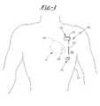
- FIG. 1shows a patient into which the system of the present invention has been operably implanted.
- FIG. 2illustrates a particular example of an implanted bio-medical device of the present invention.
- FIG. 3shows a patient into which a system of the present invention has been operably implanted.
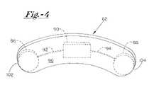
- FIG. 4illustrates an isolation view of the implantable system illustrated in FIG. 3 .
- Implantable system 10is shown in a subcutaneous implanted position external to the thoracic cavity 12 of a human patient.
- Implantable system 10preferably includes a current generating means 16 , a first electrode 18 electrically coupled to current generating means 16 via electrical conduit wire 20 , and a second electrode 22 electrically coupled to current generating means 16 .
- the patient's heart 26having a bio-medical device such as a prosthetic heart valve 28 implanted thereat.
- first and second electrodes 18 , 22are preferably positioned subcutaneously in the human patient across thoracic cavity 12 , and preferably subcutaneously along first side 32 of thoracic cavity 12 .
- first and second electrodes 18 , 22are preferably specifically positioned so as to substantially bracket prosthetic valve 28 therebetween.
- each of first and second electrodes 18 , 22are positioned such that prosthetic valve 28 is disposed substantially within an electric field extending therebetween. Such a positioning is shown in FIG. 1 by field 36 disposed substantially between first and second electrodes 18 , 22 .
- current generating means 16In operation, current generating means 16 generates a current that is directed through electrical conduit wire 20 to first electrode 18 , wherein a closed-loop circuit is enabled by current being passed from first electrode 18 to second electrode 22 through field 36 .
- the magnitude of current delivered across field 36is at least sufficient to have a therapeutic effect on electrically conductive portions of prosthetic valve 28 .
- Such a therapeutic effectincludes, for example, reducing and or eliminating the existence of coagulative and/or mineralization blood components from respective blood-contacting surfaces of prosthetic valve 28 .
- current generating means 16provides a 1–2 mA current in a pulsatile mode of delivery.
- such currentmay be provided in a continuous format.
- the American Medical Institution Guidelinesprovide that current amperage can be safely applied in a sub-threshold manner through the thoracic cavity by the following relationship; for every 1 kHz increase in frequency, current may be increased by 10 ⁇ A.
- the current applied in the present inventionmay be adjusted as desired in both amplitude and frequency, so long as it remains either at a sub-threshold level as described above, or is applied at predetermined time intervals so as not to interfere with the normal cardiac cycle.
- such currentmay be provided in sinusoidal or triangular wave forms, as well as a variety of other continuous and/or discontinuous modes.
- sensing and control meansare incorporated into the system of the present invention.
- sensing meanssuch as conventional sensing amplifiers may be connected to first and second electrodes 18 , 22 so as to electrically sense cardiac rhythms and myo potentials.
- the sensing meansdelivers responsive electrical signals to a controlling means such as a controlling circuit to indicate when a pre-defined cardiac event, such as a depolarization, is underway.
- the controller meansis operably coupled to the current generating means 16 , reception by the controller means of an electrical signal indicating a pre-defined aspect of cardiac activity initiates the controller means to interrupt and/or prevent the generation of current to first and second electrodes 18 , 22 by current generating means 16 . Such an interruption and/or prevention is maintained throughout the time period that corresponding signals are being received by the controller means from the sensor means in one or more of first and second electrodes 18 , 22 . In such a manner, generation of an electric field between first and second electrodes 18 , 22 may be automatically controlled to occur only at interval periods between critical cardiac rhythms. In other words, the controller means restricts the current generating means to supply electrical energy only during certain portions of the cardiac cycle.
- current generating means 16is a conventional implantable device that is capable of generating electrical output from a stored potential, such as in an internal battery.
- current generating means 16may be located within a conventional housing such as that of a cardiac pacemaker. Since conventional pacemaker devices have external housings which are typically fabricated from a biocompatible metal such as titanium, such an outer enclosure itself may act as second electrode 22 . In other embodiments, however, a separate electrode having its own lead wire from current generating means 16 may be provided as second electrode 22 instead of the outer housing of current generating means 16 . In any event, second electrode 22 is preferably spaced from first electrode 18 , with field 36 created therebetween having the effect of inducing current in electrically conductive portion of valve 28 .
- first and second electrodes 18 , 22are implanted subcutaneously at first side 32 of thoracic cavity 12 .
- first and second electrodes 18 , 22are preferably positioned just beneath the patient's dermal tissue. In such a manner, at least a portion of field 36 preferably passes through heart 26 , thereby exposing bio-medical device, such as mechanical heart valve 28 , to electrical current passing between first electrode 18 and second electrode 22 .
- first and second electrodes 18 , 22are not disposed at or adjacent to heart 26 .
- Devices contemplated by the present invention that, in addition to mechanical heart valves, may be targeted by the therapeutic systeminclude, for example, implanted metallic coronary stents, vascular stents, conductive arterial graft segments, and the like that are disposed in a patient's vasculature system or contained within heart 26 .
- the implanted bio-medical deviceis positioned within an area disposed generally between first and second electrodes 18 , 22 so as to be disposed within field 36 .
- electrical currentis conducted through the implanted bio-medical device during the time that current is passing from first electrode 18 to second electrode 22 .
- an electrical currentis useful in eliminating and/or preventing blood component deposits on respective surfaces of the implanted bio-medical device.
- surfaces of implanted bio-medical devices that are exposed to blood flowhave the tendency to harbor deposits of minerals and/or other coagulative components carried in the bloodstream in the absence of anti-coagulation medications taken by the patient.
- implanted heart valve 28is disposed within field 36 between first and second electrodes 18 , 22 , which results in electrical current being created in such heart valve 28 .
- An important aspect of the present inventionis that at least a portion of, for example, implanted heart valve 28 is fabricated from an electrically-conductive material such as pyrolytic carbon.
- an example implanted prosthetic heart valve 28includes a generally cylindrical valve body 50 that is sized and configured to be disposed within the area previously occupied by the native heart valve via sutures or the like.
- Prosthetic heart valve 28preferably further includes one or more pivoting valve leaflets 52 secured to valve body 50 by retention mechanisms therewithin.
- Such valve leaflets 52pivot from respective open positions, as illustrated in FIG. 2 , to respective closed positions to allow blood flow to pass through prosthetic heart valve 28 only in a direction defined by direction arrow 60 .
- valve leaflets 52 and body 50are directly in the path of the blood flow, and are therefore susceptible to the formation of deposits of coagulative blood elements thereon.
- at least leaflets 52 and body 50are fabricated from an electrically conductive material such as pyrolytic carbon so as to effectively focus electrical current passing between first and second electrodes 18 , 22 thereat.
- the system of the present inventionharnesses a basic law of physics, in that electrical current will absolutely follow the path of least electrical resistance between first and second electrodes 18 , 22 .
- the implantable bio-medical devicesuch as prosthetic heart valve 28
- a substantial portion of the electrical current passing between first and second electrodes 18 , 22will be focused at the electrically conductive portions of prosthetic valve 28 so as to accomplish a path of least electrical resistance between first and second electrodes 18 , 22 .
- portionsare preferably fabricated from a material that is significantly more electrically conductive than the body tissue and blood that is disposed generally within field 36 .
- such portions of the implanted bio-medical devicehave an electrical conductivity of at least about 10–100 times that of blood.
- the electrically conductive portions of the bio-medical devicehave a resistance value of less than about 30 ⁇ cm.
- a particularly useful electrically conductive material in such bio-medical devicesis pyrolytic carbon which has an electrical resistance value of 0.727 ⁇ cm, as compared to blood, which has an electrical resistance value of approximately 300 ⁇ cm. Such a low resistance value of the pyrolytic carbon efficiently focuses a significant portion of the electrical current passing between first and second electrodes 18 , 22 .
- first and second electrodes 18 , 22may be minimized in system 10 of the present invention while still obtaining a desired level of current in designated portions, such as valve leaflets 52 and body 50 of valve 28 to effectively prevent and/or diminish deposits of blood components thereon.
- a particular aspect of the present inventionis in focusing a substantial portion of the electrical current passing between first and second electrodes 18 , 22 at desired blood-contacting portions of the implanted bio-medical device 28 .
- the current generated by current generating means 16may be correspondingly minimized to a sub-threshold level that does not present dangers to the electrical operation of heart 26 , while still providing a sufficient degree of current at electrically conductive portions of device 28 to prevent and/or eliminate coagulative deposits thereon.
- a second important aspect of the present inventionis in the provision of first and second electrodes 18 , 22 being disposed externally of thoracic cavity 12 , so as to be substantially spaced from heart 26 .
- electrodes 18 , 22are preferably positioned at first side 32 of thoracic cavity 12 .
- Electrical impulse systemsthat require the placement of electrodes on or within critical areas of the patient's body, such as within thoracic cavity 12 , or on or within heart 26 , themselves present a difficult and dangerous operative procedure. For example, placement of such electrodes within the cavities of heart 26 is an extremely delicate procedure which can result in damage to the heart.
- the present inventionprovides for the subcutaneous placement of first and second electrodes 18 , 22 at positions in which the distance between the electrodes 18 , 22 can be minimized, and the current conducted to the surface of the implanted bio-medical device can be optimized.
- the operative procedure for subcutaneous placement of first and second electrodes 18 , 22 at locations external to the thoracic cavityis substantially more simple and less dangerous to the patient than placement of such electrodes adjacent to or within heart 26 .
- a surgeonmay be required to utilize a common tunneling tool to create a subcutaneous path for placement of electrically conductive wire 20 therein. In doing so, the surgeon is able to implant system 10 without entering the thoracic cavity 12 . As a result, the system of the present invention may be implanted without serious risks.
- first and second electrodes 18 , 22are each positioned adjacent to the innermost layer of the patient's dermal tissue.
- second electrode 22may be the outer housing itself of current generating means 16 , or may instead or additionally be a distinct electrode body electrically coupled to current generating means 16 via a distinct electrically conductive lead wire.
- separate electrodesmay be those commonly utilized in implanted electrical generation devices such as pacemakers and defibrillators.
- electrodes useful in system 10 of the present inventionmay be fabricated from, for example, titanium, platinum iridium, stainless steel, and carbon black. Such electrodes may preferably be in the form of screen, solid, and printed pattern type configurations.
- subcutaneous patch electrodeshaving a mean diameter of about 8–10 cm are utilized due to the fact that the larger the surface area of the electrode will decrease the current densities, which will be less likely to cause undesired skeletal and/or cardiac muscle stimulation.
- system 10 of the present inventionis preferably implanted, it is contemplated by the present invention that system 10 may instead be utilized externally, as on a belt attachment or similar device, and by adhesively affixing first and second electrodes 18 , 22 to respective locations of the patient, with the electrical current between such first and second electrodes maintaining a path substantially within field 36 .
- implantable system 80preferably includes a monolithic electrical field device 82 that is implantably positioned at a subcutaneous location adjacent to the thoracic cavity and spaced from an implanted medical device such as prosthetic valve 28 .
- Implantable electrical field device 82preferably includes at least first and second electrodes 86 , 88 incorporated therewith, which first and second electrodes 86 , 88 are preferably coupled to a current generating device 90 , which is preferably integrally formed with electrical field device 82 .
- current generating device 90which is separate and distinct from electrical field device 82 , and is electrically coupled to first and second electrodes 86 , 88 via electrically conductive wiring or the like.
- electrical field device 82preferably incorporates a body 96 that is fabricated from a relatively flexible bio-compatible material such as polyurethane or silicon rubber.
- First and second electrodes 86 , 88may be disposed on an outer surface of, or within body 96 .
- current generating device 90may also be selectively disposed on an outer surface or within body 96 of electrical field device 82 .
- electrical wiring leads 92 , 94preferably electrically connect one or more of first and second electrodes 86 , 88 to current generating device 90 .
- one of such first and second electrodes 86 , 88may comprise the outer housing of current generating device 90 , as described above. In such an embodiment, only a single electrically conductive lead 92 is required to electrically couple a combined current generating device and first electrode 86 to second electrode 88 .
- Body 96 of electrical field device 82is preferably sized and configured to enable the operable and implantable positioning thereof at a convenient distance from the respective implanted bio-medical device such as prosthetic valve 28 , while still providing an electric field encompassing valve 28 such than an electrical current may be induced in electrically conductive portions of prosthetic valve 28 when current is being passed between first and second electrodes 86 , 88 .
- first and second electrodes 86 , 88are contained within, or are operably attached to body 96 of electrical field device 82 .
- first and second electrodes 86 , 88are preferably positioned at respective distal ends 102 , 104 of body 96 . In this way, body 96 may be minimized in overall size to accommodate an electrical field of sufficient dimensions.
- body 96is preferably about 8–25 cm in length, 0.5–8 cm in width, and 0.1–3 cm in depth, with such dimensions being variable as a result of the flexible nature of the material making up body 96 .
- first and second electrodes 86 , 88are preferably at least about 8–10 cm apart from one another so as to establish an electrical field generally disposed therebetween that is sufficiently large in dimension so as to encompass one or more targeted bio-medical devices, such as valve 28 .
- electrical field device 82is preferably in an anterior subclavian position in a subcutaneous pocket so that the electric field generated by device 82 is sufficient so as to encompass heart 26 .
- electrical field device 82is further positioned such that the electrical field produced when electrical current is being passed between first and second electrodes 86 , 88 encompasses valve 28 so as to operably induce a therapeutic level of current at electrically conductive portions thereof.
Landscapes
- Health & Medical Sciences (AREA)
- Life Sciences & Earth Sciences (AREA)
- Animal Behavior & Ethology (AREA)
- General Health & Medical Sciences (AREA)
- Engineering & Computer Science (AREA)
- Biomedical Technology (AREA)
- Nuclear Medicine, Radiotherapy & Molecular Imaging (AREA)
- Radiology & Medical Imaging (AREA)
- Biophysics (AREA)
- Heart & Thoracic Surgery (AREA)
- Public Health (AREA)
- Veterinary Medicine (AREA)
- Prostheses (AREA)
- Materials For Medical Uses (AREA)
- Electrotherapy Devices (AREA)
- External Artificial Organs (AREA)
Abstract
Description
Claims (9)
Priority Applications (10)
| Application Number | Priority Date | Filing Date | Title |
|---|---|---|---|
| US10/889,328US7167746B2 (en) | 2004-07-12 | 2004-07-12 | Anti-coagulation and demineralization system for conductive medical devices |
| DE602005014648TDE602005014648D1 (en) | 2004-07-12 | 2005-07-08 | Anti-inflammatory and demineralizing system for conductive medical devices |
| PCT/US2005/024502WO2006017213A2 (en) | 2004-07-12 | 2005-07-08 | Anti-coagulation and demineralization system for conductive medical devices |
| AT05770758TATE432106T1 (en) | 2004-07-12 | 2005-07-08 | ANTICOLOTTING AND DEMINERALIZING SYSTEM FOR CONDUCTIVE MEDICAL DEVICES |
| JP2007521529AJP4941992B2 (en) | 2004-07-12 | 2005-07-08 | Anticoagulation and demineralization system for conductive medical devices |
| AU2005271840AAU2005271840B9 (en) | 2004-07-12 | 2005-07-08 | Anti-coagulation and demineralization system for conductive medical devices |
| CA002572385ACA2572385A1 (en) | 2004-07-12 | 2005-07-08 | Anti-coagulation and demineralization system for conductive medical devices |
| EP05770758AEP1778342B1 (en) | 2004-07-12 | 2005-07-08 | Anti-coagulation and demineralization system for conductive medical devices |
| US11/617,507US8565872B2 (en) | 2004-07-12 | 2006-12-28 | Anti-coagulation and demineralization system for conductive medical devices |
| IL180541AIL180541A (en) | 2004-07-12 | 2007-01-04 | Anti-coagulation and demineralization system for conductive medical devices |
Applications Claiming Priority (1)
| Application Number | Priority Date | Filing Date | Title |
|---|---|---|---|
| US10/889,328US7167746B2 (en) | 2004-07-12 | 2004-07-12 | Anti-coagulation and demineralization system for conductive medical devices |
Related Child Applications (1)
| Application Number | Title | Priority Date | Filing Date |
|---|---|---|---|
| US11/617,507ContinuationUS8565872B2 (en) | 2004-07-12 | 2006-12-28 | Anti-coagulation and demineralization system for conductive medical devices |
Publications (2)
| Publication Number | Publication Date |
|---|---|
| US20060009804A1 US20060009804A1 (en) | 2006-01-12 |
| US7167746B2true US7167746B2 (en) | 2007-01-23 |
Family
ID=35542377
Family Applications (2)
| Application Number | Title | Priority Date | Filing Date |
|---|---|---|---|
| US10/889,328Expired - LifetimeUS7167746B2 (en) | 2004-07-12 | 2004-07-12 | Anti-coagulation and demineralization system for conductive medical devices |
| US11/617,507Active2027-07-23US8565872B2 (en) | 2004-07-12 | 2006-12-28 | Anti-coagulation and demineralization system for conductive medical devices |
Family Applications After (1)
| Application Number | Title | Priority Date | Filing Date |
|---|---|---|---|
| US11/617,507Active2027-07-23US8565872B2 (en) | 2004-07-12 | 2006-12-28 | Anti-coagulation and demineralization system for conductive medical devices |
Country Status (9)
| Country | Link |
|---|---|
| US (2) | US7167746B2 (en) |
| EP (1) | EP1778342B1 (en) |
| JP (1) | JP4941992B2 (en) |
| AT (1) | ATE432106T1 (en) |
| AU (1) | AU2005271840B9 (en) |
| CA (1) | CA2572385A1 (en) |
| DE (1) | DE602005014648D1 (en) |
| IL (1) | IL180541A (en) |
| WO (1) | WO2006017213A2 (en) |
Cited By (15)
| Publication number | Priority date | Publication date | Assignee | Title |
|---|---|---|---|---|
| US20100016676A1 (en)* | 2008-07-15 | 2010-01-21 | Nellcor Puritan Bennett Ireland | Systems And Methods For Adaptively Filtering Signals |
| US20100014725A1 (en)* | 2008-07-15 | 2010-01-21 | Nellcor Puritan Bennett Ireland | Systems And Methods For Filtering A Signal Using A Continuous Wavelet Transform |
| US20110021941A1 (en)* | 2009-07-23 | 2011-01-27 | Nellcor Puritan Bennett Ireland | Systems and methods for respiration monitoring |
| US20110021892A1 (en)* | 2009-07-23 | 2011-01-27 | Nellcor Puritan Bennett Ireland | Systems and methods for respiration monitoring |
| US20110026784A1 (en)* | 2009-07-30 | 2011-02-03 | Nellcor Puritan Bennett Ireland | Systems And Methods For Determining Physiological Information Using Selective Transform Data |
| US20110077484A1 (en)* | 2009-09-30 | 2011-03-31 | Nellcor Puritan Bennett Ireland | Systems And Methods For Identifying Non-Corrupted Signal Segments For Use In Determining Physiological Parameters |
| US20110196478A1 (en)* | 2010-02-10 | 2011-08-11 | Beoptima Inc. | Devices and methods for lumen treatment |
| US8255029B2 (en) | 2003-02-27 | 2012-08-28 | Nellcor Puritan Bennett Llc | Method of analyzing and processing signals |
| US8504151B2 (en) | 2006-08-24 | 2013-08-06 | Cardiac Pacemakers, Inc. | Integrated cardiac rhythm management system with heart valve |
| US9039753B2 (en) | 2012-09-05 | 2015-05-26 | Jeff Thramann | System and method to electrically charge implantable devices |
| US10022068B2 (en) | 2013-10-28 | 2018-07-17 | Covidien Lp | Systems and methods for detecting held breath events |
| US10500382B2 (en) | 2016-11-10 | 2019-12-10 | Medtronic Vascular, Inc. | Drug-filled stents with filaments for increased lumen surface area and method of manufacture thereof |
| US10617540B2 (en) | 2016-11-10 | 2020-04-14 | Medtronic Vascular, Inc. | Stents formed from dissimilar metals for tissue growth control |
| US10779972B2 (en) | 2016-11-10 | 2020-09-22 | Medtronic Vascular, Inc. | Drug-filled stents to prevent vessel micro-injuries and methods of manufacture thereof |
| US11511020B2 (en)* | 2009-09-28 | 2022-11-29 | Timothy J. Ryan | Charged grafts and methods for using them |
Families Citing this family (35)
| Publication number | Priority date | Publication date | Assignee | Title |
|---|---|---|---|---|
| US6440164B1 (en)* | 1999-10-21 | 2002-08-27 | Scimed Life Systems, Inc. | Implantable prosthetic valve |
| US6602286B1 (en) | 2000-10-26 | 2003-08-05 | Ernst Peter Strecker | Implantable valve system |
| US7007698B2 (en)* | 2002-04-03 | 2006-03-07 | Boston Scientific Corporation | Body lumen closure |
| US6752828B2 (en)* | 2002-04-03 | 2004-06-22 | Scimed Life Systems, Inc. | Artificial valve |
| US7399313B2 (en)* | 2002-06-07 | 2008-07-15 | Brown Peter S | Endovascular graft with separable sensors |
| AU2003285943B2 (en)* | 2002-10-24 | 2008-08-21 | Boston Scientific Limited | Venous valve apparatus and method |
| US6945957B2 (en) | 2002-12-30 | 2005-09-20 | Scimed Life Systems, Inc. | Valve treatment catheter and methods |
| US7380163B2 (en)* | 2003-04-23 | 2008-05-27 | Dot Hill Systems Corporation | Apparatus and method for deterministically performing active-active failover of redundant servers in response to a heartbeat link failure |
| US7854761B2 (en) | 2003-12-19 | 2010-12-21 | Boston Scientific Scimed, Inc. | Methods for venous valve replacement with a catheter |
| US8128681B2 (en) | 2003-12-19 | 2012-03-06 | Boston Scientific Scimed, Inc. | Venous valve apparatus, system, and method |
| US7167746B2 (en)* | 2004-07-12 | 2007-01-23 | Ats Medical, Inc. | Anti-coagulation and demineralization system for conductive medical devices |
| US7566343B2 (en) | 2004-09-02 | 2009-07-28 | Boston Scientific Scimed, Inc. | Cardiac valve, system, and method |
| US20060173490A1 (en)* | 2005-02-01 | 2006-08-03 | Boston Scientific Scimed, Inc. | Filter system and method |
| US7854755B2 (en) | 2005-02-01 | 2010-12-21 | Boston Scientific Scimed, Inc. | Vascular catheter, system, and method |
| US7670368B2 (en)* | 2005-02-07 | 2010-03-02 | Boston Scientific Scimed, Inc. | Venous valve apparatus, system, and method |
| US7780722B2 (en)* | 2005-02-07 | 2010-08-24 | Boston Scientific Scimed, Inc. | Venous valve apparatus, system, and method |
| US7867274B2 (en)* | 2005-02-23 | 2011-01-11 | Boston Scientific Scimed, Inc. | Valve apparatus, system and method |
| US7722666B2 (en)* | 2005-04-15 | 2010-05-25 | Boston Scientific Scimed, Inc. | Valve apparatus, system and method |
| US8012198B2 (en) | 2005-06-10 | 2011-09-06 | Boston Scientific Scimed, Inc. | Venous valve, system, and method |
| US7569071B2 (en)* | 2005-09-21 | 2009-08-04 | Boston Scientific Scimed, Inc. | Venous valve, system, and method with sinus pocket |
| US7799038B2 (en)* | 2006-01-20 | 2010-09-21 | Boston Scientific Scimed, Inc. | Translumenal apparatus, system, and method |
| US9844667B2 (en) | 2006-04-12 | 2017-12-19 | Medtronic Ats Medical Inc. | System for conditioning surfaces in vivo |
| US20080126131A1 (en)* | 2006-07-17 | 2008-05-29 | Walgreen Co. | Predictive Modeling And Risk Stratification Of A Medication Therapy Regimen |
| CN102292053A (en) | 2008-09-29 | 2011-12-21 | 卡迪尔克阀门技术公司 | Heart valve |
| WO2010040009A1 (en) | 2008-10-01 | 2010-04-08 | Cardiaq Valve Technologies, Inc. | Delivery system for vascular implant |
| CA2961053C (en) | 2009-04-15 | 2019-04-30 | Edwards Lifesciences Cardiaq Llc | Vascular implant and delivery system |
| JP5607744B2 (en)* | 2009-10-29 | 2014-10-15 | エイオーテック インターナショナル パブリック リミティド カンパニー | Polyurethane header formed directly on an implantable electrical device |
| US8579964B2 (en) | 2010-05-05 | 2013-11-12 | Neovasc Inc. | Transcatheter mitral valve prosthesis |
| US9554897B2 (en) | 2011-04-28 | 2017-01-31 | Neovasc Tiara Inc. | Methods and apparatus for engaging a valve prosthesis with tissue |
| US9308087B2 (en) | 2011-04-28 | 2016-04-12 | Neovasc Tiara Inc. | Sequentially deployed transcatheter mitral valve prosthesis |
| US9345573B2 (en) | 2012-05-30 | 2016-05-24 | Neovasc Tiara Inc. | Methods and apparatus for loading a prosthesis onto a delivery system |
| US10583002B2 (en) | 2013-03-11 | 2020-03-10 | Neovasc Tiara Inc. | Prosthetic valve with anti-pivoting mechanism |
| US9681951B2 (en) | 2013-03-14 | 2017-06-20 | Edwards Lifesciences Cardiaq Llc | Prosthesis with outer skirt and anchors |
| US9572665B2 (en) | 2013-04-04 | 2017-02-21 | Neovasc Tiara Inc. | Methods and apparatus for delivering a prosthetic valve to a beating heart |
| US9987129B2 (en) | 2014-04-16 | 2018-06-05 | Alma Mater Studiorum—Università di Bologna | Heart valve prosthesis with integrated electronic circuit for measuring intravalvular electrical impedance, and system for monitoring functionality of the prosthesis |
Citations (32)
| Publication number | Priority date | Publication date | Assignee | Title |
|---|---|---|---|---|
| US3579645A (en) | 1969-04-30 | 1971-05-25 | Gulf Energy & Environ Systems | Cardiac valve occluder having a density approximately equal to blood |
| US3726762A (en) | 1971-05-19 | 1973-04-10 | Intelectron Corp | Blood storage method |
| US4008710A (en) | 1973-08-11 | 1977-02-22 | Horst Chmiel | Blood pump |
| US4038702A (en) | 1973-09-21 | 1977-08-02 | Philip Nicholas Sawyer | Electrochemical and chemical methods for production of non-thrombogenic metal heart valves |
| US4600405A (en) | 1985-10-07 | 1986-07-15 | Zibelin Henry S | Mechanical heart |
| US4753652A (en) | 1984-05-04 | 1988-06-28 | Children's Medical Center Corporation | Biomaterial implants which resist calcification |
| US4769032A (en) | 1986-03-05 | 1988-09-06 | Bruce Steinberg | Prosthetic valve and monitoring system and method |
| US4979955A (en) | 1988-06-06 | 1990-12-25 | Smith Robert M | Power assisted prosthetic heart valve |
| US5135538A (en) | 1989-09-29 | 1992-08-04 | General Motors Corporation | Electromagnetically controlled heart valve |
| US5443446A (en) | 1991-04-04 | 1995-08-22 | Shturman Cardiology Systems, Inc. | Method and apparatus for in vivo heart valve decalcification |
| US5487760A (en) | 1994-03-08 | 1996-01-30 | Ats Medical, Inc. | Heart valve prosthesis incorporating electronic sensing, monitoring and/or pacing circuitry |
| US5530355A (en) | 1993-05-13 | 1996-06-25 | Doty Scientific, Inc. | Solenoidal, octopolar, transverse gradient coils |
| US5603731A (en) | 1994-11-21 | 1997-02-18 | Whitney; Douglass G. | Method and apparatus for thwarting thrombosis |
| US5800536A (en) | 1997-05-09 | 1998-09-01 | The United States Of America As Represented By The Secretary Of The Navy | Passive piezoelectric prosthesis for the inner ear |
| US5810015A (en) | 1995-09-01 | 1998-09-22 | Strato/Infusaid, Inc. | Power supply for implantable device |
| US5853005A (en) | 1996-05-02 | 1998-12-29 | The United States Of America As Represented By The Secretary Of The Army | Acoustic monitoring system |
| US5869189A (en) | 1994-04-19 | 1999-02-09 | Massachusetts Institute Of Technology | Composites for structural control |
| US5919223A (en) | 1974-10-24 | 1999-07-06 | Goldfarb; David | Graphite impregnated prosthetic vascular graft materials |
| US5928224A (en) | 1997-01-24 | 1999-07-27 | Hearten Medical, Inc. | Device for the treatment of damaged heart valve leaflets and methods of using the device |
| US5944751A (en) | 1993-09-17 | 1999-08-31 | Zertl Medical, Inc. | Vibratory heart valve |
| US6047700A (en) | 1998-03-30 | 2000-04-11 | Arthrocare Corporation | Systems and methods for electrosurgical removal of calcified deposits |
| US6143035A (en) | 1999-01-28 | 2000-11-07 | Depuy Orthopaedics, Inc. | Implanted bone stimulator and prosthesis system and method of enhancing bone growth |
| US6152955A (en) | 1992-11-24 | 2000-11-28 | Cardiac Pacemakers, Inc. | Implantable conformal coil patch electrode with multiple conductive elements for cardioversion and defibrillation |
| US6201991B1 (en) | 1999-05-07 | 2001-03-13 | Heart Care Associates, Llc | Method of prevention and treatment of atherosclerosis and article of manufacture therefor |
| US6394096B1 (en) | 1998-07-15 | 2002-05-28 | Corazon Technologies, Inc. | Method and apparatus for treatment of cardiovascular tissue mineralization |
| US6463323B1 (en) | 1998-11-12 | 2002-10-08 | Em Vascular, Inc. | Electrically mediated angiogenesis |
| US20020169480A1 (en) | 2001-05-10 | 2002-11-14 | Qingsheng Zhu | Method and device for preventing plaque formation in coronary arteries |
| US6505080B1 (en) | 1999-05-04 | 2003-01-07 | Medtronic, Inc. | Method and apparatus for inhibiting or minimizing calcification of aortic valves |
| US6534538B2 (en) | 1999-09-21 | 2003-03-18 | Mayo Foundation For Medical Education And Research | Method for slowing heart valve degeneration |
| US6551990B2 (en) | 1998-12-07 | 2003-04-22 | University Of Washington | Methods of inhibiting ectopic calcification |
| US6556872B2 (en) | 1999-08-24 | 2003-04-29 | Ev Vascular, Inc. | Therapeutic device and method for treating diseases of cardiac muscle |
| US6560489B2 (en) | 1999-08-24 | 2003-05-06 | Em Vascular, Inc. | Therapeutic device and method for treating diseases of cardiac muscle |
Family Cites Families (39)
| Publication number | Priority date | Publication date | Assignee | Title |
|---|---|---|---|---|
| US3609768A (en) | 1969-06-16 | 1971-10-05 | Becton Dickinson Co | Anticoagulant material having charged electrostatic surfaces suitable for use in prosthetic devices |
| US3757794A (en) | 1971-08-19 | 1973-09-11 | American Optical Corp | Temporary power supply for a heart-stimulating device |
| SE7610696L (en) | 1976-09-28 | 1978-03-29 | Reenstierna Bertil | KIT AND DEVICE FOR INSERTING AND FIXING "PACEMAKER - ELECTROD" IN (HUMAN) HEART |
| JPH01500730A (en) | 1986-08-20 | 1989-03-16 | ザ・チャイルドレンズ・メディカル・センター・コーポレーション | biological material graft |
| US5207706A (en) | 1988-10-05 | 1993-05-04 | Menaker M D Gerald | Method and means for gold-coating implantable intravascular devices |
| US5464438A (en) | 1988-10-05 | 1995-11-07 | Menaker; Gerald J. | Gold coating means for limiting thromboses in implantable grafts |
| US4945912A (en) | 1988-11-25 | 1990-08-07 | Sensor Electronics, Inc. | Catheter with radiofrequency heating applicator |
| US4969463A (en)* | 1989-06-06 | 1990-11-13 | Cardiac Pacemakers, Inc. | Defibrillation electrode and method for employing gatling discharge defibrillation |
| US5203348A (en)* | 1990-06-06 | 1993-04-20 | Cardiac Pacemakers, Inc. | Subcutaneous defibrillation electrodes |
| JPH04253864A (en)* | 1991-02-01 | 1992-09-09 | Sumitomo Pharmaceut Co Ltd | Sterilization method, prevention of bacteria adhesion to medical material, sterilization of medical material and medical material |
| US5078763A (en) | 1991-02-13 | 1992-01-07 | Blount Gillette James E | Air filter cleaning device |
| AU1672492A (en)* | 1991-05-03 | 1992-12-21 | University Technologies International Inc. | Biofilm reduction method |
| AU1736392A (en)* | 1991-06-11 | 1992-12-17 | Raymond E. Ideker | Reduced current cardiac pacing apparatus |
| US5348553A (en) | 1991-12-18 | 1994-09-20 | Whitney Douglass G | Method for promoting blood vessel healing |
| US5281218A (en) | 1992-06-05 | 1994-01-25 | Cardiac Pathways Corporation | Catheter having needle electrode for radiofrequency ablation |
| EP0623150A4 (en) | 1992-11-19 | 1999-08-25 | Univ Case Western Reserve | Nonthrombogenic implant surfaces. |
| US5530335A (en)* | 1993-05-11 | 1996-06-25 | Trw Inc. | Battery regulated bus spacecraft power control system |
| DE4316673C1 (en)* | 1993-05-12 | 1995-01-12 | Ethicon Gmbh | Flexible implant |
| EP0741585A1 (en) | 1994-01-21 | 1996-11-13 | Brown University Research Foundation | Biocompatible implants |
| DE19506188C2 (en) | 1995-02-22 | 2003-03-06 | Miladin Lazarov | Implant and its use |
| US5924975A (en) | 1995-08-30 | 1999-07-20 | International Business Machines Corporation | Linear pump |
| US5800421A (en) | 1996-06-12 | 1998-09-01 | Lemelson; Jerome H. | Medical devices using electrosensitive gels |
| US5895419A (en) | 1996-09-30 | 1999-04-20 | St. Jude Medical, Inc. | Coated prosthetic cardiac device |
| US6395024B1 (en)* | 1997-05-20 | 2002-05-28 | Triflo Medical, Inc. | Mechanical heart valve |
| CA2318266A1 (en) | 1998-01-19 | 1999-07-22 | Medquest Products, Inc. | Method and apparatus for providing a conductive, amorphous non-stick coating |
| CA2321671C (en) | 1998-03-02 | 2009-07-14 | Atrionix, Inc. | Tissue ablation system and method for forming long linear lesion |
| US6206914B1 (en) | 1998-04-30 | 2001-03-27 | Medtronic, Inc. | Implantable system with drug-eluting cells for on-demand local drug delivery |
| US20030069601A1 (en) | 1998-12-15 | 2003-04-10 | Closys Corporation | Clotting cascade initiating apparatus and methods of use |
| US6282444B1 (en)* | 1999-08-31 | 2001-08-28 | Pacesetter, Inc. | Implantable device with electrical infection control |
| US6658288B1 (en) | 2000-05-05 | 2003-12-02 | Endovascular Technologies, Inc. | Apparatus and method for aiding thrombosis through the application of electric potential |
| JP2002200172A (en)* | 2000-08-27 | 2002-07-16 | Kazuyo Seko | Medical tube and artificial organ preventing microbial infection and thrombosis |
| US7065407B2 (en)* | 2000-09-18 | 2006-06-20 | Cameron Health, Inc. | Duckbill-shaped implantable cardioverter-defibrillator canister and method of use |
| US7149575B2 (en)* | 2000-09-18 | 2006-12-12 | Cameron Health, Inc. | Subcutaneous cardiac stimulator device having an anteriorly positioned electrode |
| US20020120297A1 (en) | 2001-02-26 | 2002-08-29 | Shadduck John H. | Vaso-occlusive implants for interventional neuroradiology |
| US20030082148A1 (en) | 2001-10-31 | 2003-05-01 | Florian Ludwig | Methods and device compositions for the recruitment of cells to blood contacting surfaces in vivo |
| US20040215310A1 (en) | 2002-01-17 | 2004-10-28 | Omar Amirana | Stent and delivery method for applying RF energy to a pulmonary vein and the atrial wall around its ostium to eliminate atrial fibrillation while preventing stenosis of the pulmonary vein thereafter |
| US20040015104A1 (en)* | 2002-02-11 | 2004-01-22 | Gold-T Tech, Inc. | Method for preventing thrombus formation |
| WO2005004754A2 (en) | 2003-06-30 | 2005-01-20 | Js Vascular, Inc. | Subcutaneous implantable non-thrombogenic mechanical devices |
| US7167746B2 (en)* | 2004-07-12 | 2007-01-23 | Ats Medical, Inc. | Anti-coagulation and demineralization system for conductive medical devices |
- 2004
- 2004-07-12USUS10/889,328patent/US7167746B2/ennot_activeExpired - Lifetime
- 2005
- 2005-07-08JPJP2007521529Apatent/JP4941992B2/ennot_activeExpired - Fee Related
- 2005-07-08AUAU2005271840Apatent/AU2005271840B9/ennot_activeCeased
- 2005-07-08DEDE602005014648Tpatent/DE602005014648D1/ennot_activeExpired - Lifetime
- 2005-07-08CACA002572385Apatent/CA2572385A1/ennot_activeAbandoned
- 2005-07-08WOPCT/US2005/024502patent/WO2006017213A2/enactiveApplication Filing
- 2005-07-08EPEP05770758Apatent/EP1778342B1/ennot_activeExpired - Lifetime
- 2005-07-08ATAT05770758Tpatent/ATE432106T1/ennot_activeIP Right Cessation
- 2006
- 2006-12-28USUS11/617,507patent/US8565872B2/enactiveActive
- 2007
- 2007-01-04ILIL180541Apatent/IL180541A/ennot_activeIP Right Cessation
Patent Citations (35)
| Publication number | Priority date | Publication date | Assignee | Title |
|---|---|---|---|---|
| US3579645A (en) | 1969-04-30 | 1971-05-25 | Gulf Energy & Environ Systems | Cardiac valve occluder having a density approximately equal to blood |
| US3726762A (en) | 1971-05-19 | 1973-04-10 | Intelectron Corp | Blood storage method |
| US4008710A (en) | 1973-08-11 | 1977-02-22 | Horst Chmiel | Blood pump |
| US4038702A (en) | 1973-09-21 | 1977-08-02 | Philip Nicholas Sawyer | Electrochemical and chemical methods for production of non-thrombogenic metal heart valves |
| US5919223A (en) | 1974-10-24 | 1999-07-06 | Goldfarb; David | Graphite impregnated prosthetic vascular graft materials |
| US4753652A (en) | 1984-05-04 | 1988-06-28 | Children's Medical Center Corporation | Biomaterial implants which resist calcification |
| US4600405A (en) | 1985-10-07 | 1986-07-15 | Zibelin Henry S | Mechanical heart |
| US4769032A (en) | 1986-03-05 | 1988-09-06 | Bruce Steinberg | Prosthetic valve and monitoring system and method |
| US4979955A (en) | 1988-06-06 | 1990-12-25 | Smith Robert M | Power assisted prosthetic heart valve |
| US5135538A (en) | 1989-09-29 | 1992-08-04 | General Motors Corporation | Electromagnetically controlled heart valve |
| US5443446A (en) | 1991-04-04 | 1995-08-22 | Shturman Cardiology Systems, Inc. | Method and apparatus for in vivo heart valve decalcification |
| US6152955A (en) | 1992-11-24 | 2000-11-28 | Cardiac Pacemakers, Inc. | Implantable conformal coil patch electrode with multiple conductive elements for cardioversion and defibrillation |
| US5530355A (en) | 1993-05-13 | 1996-06-25 | Doty Scientific, Inc. | Solenoidal, octopolar, transverse gradient coils |
| US5944751A (en) | 1993-09-17 | 1999-08-31 | Zertl Medical, Inc. | Vibratory heart valve |
| US5487760A (en) | 1994-03-08 | 1996-01-30 | Ats Medical, Inc. | Heart valve prosthesis incorporating electronic sensing, monitoring and/or pacing circuitry |
| US5869189A (en) | 1994-04-19 | 1999-02-09 | Massachusetts Institute Of Technology | Composites for structural control |
| US5603731A (en) | 1994-11-21 | 1997-02-18 | Whitney; Douglass G. | Method and apparatus for thwarting thrombosis |
| US5954058A (en) | 1995-09-01 | 1999-09-21 | Strato/Infusaid, Inc. | Power supply for implantable device |
| US5810015A (en) | 1995-09-01 | 1998-09-22 | Strato/Infusaid, Inc. | Power supply for implantable device |
| US5853005A (en) | 1996-05-02 | 1998-12-29 | The United States Of America As Represented By The Secretary Of The Army | Acoustic monitoring system |
| US6083219A (en) | 1997-01-24 | 2000-07-04 | Laufer; Michael D. | Device for the treatment of damaged heart value leaflets and method of using the device |
| US5928224A (en) | 1997-01-24 | 1999-07-27 | Hearten Medical, Inc. | Device for the treatment of damaged heart valve leaflets and methods of using the device |
| US5800536A (en) | 1997-05-09 | 1998-09-01 | The United States Of America As Represented By The Secretary Of The Navy | Passive piezoelectric prosthesis for the inner ear |
| US6047700A (en) | 1998-03-30 | 2000-04-11 | Arthrocare Corporation | Systems and methods for electrosurgical removal of calcified deposits |
| US6394096B1 (en) | 1998-07-15 | 2002-05-28 | Corazon Technologies, Inc. | Method and apparatus for treatment of cardiovascular tissue mineralization |
| US6463323B1 (en) | 1998-11-12 | 2002-10-08 | Em Vascular, Inc. | Electrically mediated angiogenesis |
| US6551990B2 (en) | 1998-12-07 | 2003-04-22 | University Of Washington | Methods of inhibiting ectopic calcification |
| US6143035A (en) | 1999-01-28 | 2000-11-07 | Depuy Orthopaedics, Inc. | Implanted bone stimulator and prosthesis system and method of enhancing bone growth |
| US6505080B1 (en) | 1999-05-04 | 2003-01-07 | Medtronic, Inc. | Method and apparatus for inhibiting or minimizing calcification of aortic valves |
| US20030093124A1 (en) | 1999-05-04 | 2003-05-15 | Richard Sutton | Method and apparatus for inhibiting or minimizing calcification of aortic valves |
| US6201991B1 (en) | 1999-05-07 | 2001-03-13 | Heart Care Associates, Llc | Method of prevention and treatment of atherosclerosis and article of manufacture therefor |
| US6556872B2 (en) | 1999-08-24 | 2003-04-29 | Ev Vascular, Inc. | Therapeutic device and method for treating diseases of cardiac muscle |
| US6560489B2 (en) | 1999-08-24 | 2003-05-06 | Em Vascular, Inc. | Therapeutic device and method for treating diseases of cardiac muscle |
| US6534538B2 (en) | 1999-09-21 | 2003-03-18 | Mayo Foundation For Medical Education And Research | Method for slowing heart valve degeneration |
| US20020169480A1 (en) | 2001-05-10 | 2002-11-14 | Qingsheng Zhu | Method and device for preventing plaque formation in coronary arteries |
Cited By (29)
| Publication number | Priority date | Publication date | Assignee | Title |
|---|---|---|---|---|
| US8255029B2 (en) | 2003-02-27 | 2012-08-28 | Nellcor Puritan Bennett Llc | Method of analyzing and processing signals |
| US10182764B2 (en) | 2003-02-27 | 2019-01-22 | Nellcor Puritan Bennett Ireland | Method of analyzing and processing signals |
| US9220459B2 (en) | 2003-02-27 | 2015-12-29 | Nellcor Puritan Bennett Ireland | Method of analyzing and processing signals |
| US9220460B2 (en) | 2003-02-27 | 2015-12-29 | Nellcor Puritan Bennett Ireland | Method of analyzing and processing signals |
| US9198616B2 (en) | 2003-02-27 | 2015-12-01 | Nellcor Puritan Bennett Ireland | Method of analyzing and processing signals |
| US9192336B2 (en) | 2003-02-27 | 2015-11-24 | Nellcor Puritan Bennett Ireland | Method of analyzing and processing signals |
| US8504151B2 (en) | 2006-08-24 | 2013-08-06 | Cardiac Pacemakers, Inc. | Integrated cardiac rhythm management system with heart valve |
| US9066691B2 (en) | 2008-07-15 | 2015-06-30 | Nellcor Puritan Bennett Ireland | Using a continuous wavelet transform to generate a reference signal |
| US20100016696A1 (en)* | 2008-07-15 | 2010-01-21 | Nellcor Puritan Bennett Ireland | Systems and methods for generating reference signals |
| US20100014723A1 (en)* | 2008-07-15 | 2010-01-21 | Nellcor Puritan Bennett Ireland | Signal processing systems and methods using multiple signals |
| US8235911B2 (en) | 2008-07-15 | 2012-08-07 | Nellcor Puritan Bennett Ireland | Methods and systems for filtering a signal according to a signal model and continuous wavelet transform techniques |
| US8385675B2 (en) | 2008-07-15 | 2013-02-26 | Nellcor Puritan Bennett Ireland | Systems and methods for filtering a signal using a continuous wavelet transform |
| US9259188B2 (en) | 2008-07-15 | 2016-02-16 | Nellcor Puritan Bennett Ireland | Methods and systems for filtering a signal according to a signal model and continuous wavelet transform techniques |
| US20100016676A1 (en)* | 2008-07-15 | 2010-01-21 | Nellcor Puritan Bennett Ireland | Systems And Methods For Adaptively Filtering Signals |
| US9031627B2 (en) | 2008-07-15 | 2015-05-12 | Nellcor Puritan Bennett Ireland | Signal processing systems and methods using multiple signals |
| US20100016695A1 (en)* | 2008-07-15 | 2010-01-21 | Nellcor Puritan Bennett Ireland | Methods And Systems For Filtering A Signal According To A Signal Model And Continuous Wavelet Transform Techniques |
| US20100014725A1 (en)* | 2008-07-15 | 2010-01-21 | Nellcor Puritan Bennett Ireland | Systems And Methods For Filtering A Signal Using A Continuous Wavelet Transform |
| US20110021892A1 (en)* | 2009-07-23 | 2011-01-27 | Nellcor Puritan Bennett Ireland | Systems and methods for respiration monitoring |
| US20110021941A1 (en)* | 2009-07-23 | 2011-01-27 | Nellcor Puritan Bennett Ireland | Systems and methods for respiration monitoring |
| US8478376B2 (en) | 2009-07-30 | 2013-07-02 | Nellcor Puritan Bennett Ireland | Systems and methods for determining physiological information using selective transform data |
| US20110026784A1 (en)* | 2009-07-30 | 2011-02-03 | Nellcor Puritan Bennett Ireland | Systems And Methods For Determining Physiological Information Using Selective Transform Data |
| US11511020B2 (en)* | 2009-09-28 | 2022-11-29 | Timothy J. Ryan | Charged grafts and methods for using them |
| US20110077484A1 (en)* | 2009-09-30 | 2011-03-31 | Nellcor Puritan Bennett Ireland | Systems And Methods For Identifying Non-Corrupted Signal Segments For Use In Determining Physiological Parameters |
| US20110196478A1 (en)* | 2010-02-10 | 2011-08-11 | Beoptima Inc. | Devices and methods for lumen treatment |
| US9039753B2 (en) | 2012-09-05 | 2015-05-26 | Jeff Thramann | System and method to electrically charge implantable devices |
| US10022068B2 (en) | 2013-10-28 | 2018-07-17 | Covidien Lp | Systems and methods for detecting held breath events |
| US10500382B2 (en) | 2016-11-10 | 2019-12-10 | Medtronic Vascular, Inc. | Drug-filled stents with filaments for increased lumen surface area and method of manufacture thereof |
| US10617540B2 (en) | 2016-11-10 | 2020-04-14 | Medtronic Vascular, Inc. | Stents formed from dissimilar metals for tissue growth control |
| US10779972B2 (en) | 2016-11-10 | 2020-09-22 | Medtronic Vascular, Inc. | Drug-filled stents to prevent vessel micro-injuries and methods of manufacture thereof |
Also Published As
| Publication number | Publication date |
|---|---|
| WO2006017213A3 (en) | 2006-08-24 |
| AU2005271840B2 (en) | 2011-06-16 |
| AU2005271840A1 (en) | 2006-02-16 |
| CA2572385A1 (en) | 2006-02-16 |
| JP4941992B2 (en) | 2012-05-30 |
| US8565872B2 (en) | 2013-10-22 |
| US20070156214A1 (en) | 2007-07-05 |
| AU2005271840B9 (en) | 2011-07-21 |
| EP1778342B1 (en) | 2009-05-27 |
| EP1778342A4 (en) | 2008-02-13 |
| IL180541A (en) | 2010-12-30 |
| ATE432106T1 (en) | 2009-06-15 |
| EP1778342A2 (en) | 2007-05-02 |
| JP2008505729A (en) | 2008-02-28 |
| IL180541A0 (en) | 2007-06-03 |
| WO2006017213A2 (en) | 2006-02-16 |
| DE602005014648D1 (en) | 2009-07-09 |
| US20060009804A1 (en) | 2006-01-12 |
Similar Documents
| Publication | Publication Date | Title |
|---|---|---|
| US7167746B2 (en) | Anti-coagulation and demineralization system for conductive medical devices | |
| JP2008505729A5 (en) | ||
| US5476499A (en) | Medical electrode lead with atrial electrode at the distal and ventricular electrode between the distal and proximal ends | |
| US6233484B1 (en) | Apparatus and method for controlling the contractility of muscles | |
| US7158832B2 (en) | Electrode designs and methods of use for cardiovascular reflex control devices | |
| US6850801B2 (en) | Mapping methods for cardiovascular reflex control devices | |
| EP2399644B1 (en) | Devices for cardiovascular reflex control | |
| US6415178B1 (en) | Fencing of cardiac muscles | |
| US20060004417A1 (en) | Baroreflex activation for arrhythmia treatment | |
| US6505080B1 (en) | Method and apparatus for inhibiting or minimizing calcification of aortic valves | |
| JP2001517995A (en) | Intracardiac lead for cardiac pacing or defibrillation through the coronary sinus | |
| US7274960B2 (en) | Method and apparatus for treating aneurysms by electrostimulation | |
| Mayr et al. | Basic design and construction of the Vienna FES implants: existing solutions and prospects for new generations of implants | |
| JP7352305B2 (en) | Control system for an implantable stimulator for stimulating the vagus nerve | |
| US7738953B2 (en) | Method and device for preventing plaque formation in coronary arteries | |
| US5195518A (en) | System and method for enhancing collateral cardiac blood flow | |
| CN101198372A (en) | Leadless Implantable Intravascular Electrophysiology Devices for Neuro/Cardiovascular Detection and Stimulation |
Legal Events
| Date | Code | Title | Description |
|---|---|---|---|
| AS | Assignment | Owner name:ATS MEDDICAL, INC., MINNESOTA Free format text:ASSIGNMENT OF ASSIGNORS INTEREST;ASSIGNOR:PEDERSON, BRIAN D.;REEL/FRAME:015573/0774 Effective date:20040630 | |
| AS | Assignment | Owner name:ATS MEDICAL, INC., MINNESOTA Free format text:CORRECTIVE ASSIGNMENT TO CORRECT ASSIGNEE NAME. PREVIOUSLY RECORDED ON REEL 015573, FRAME 0774;ASSIGNOR:PEDERSON, BRIAN D.;REEL/FRAME:015669/0592 Effective date:20040630 | |
| STCF | Information on status: patent grant | Free format text:PATENTED CASE | |
| FPAY | Fee payment | Year of fee payment:4 | |
| FEPP | Fee payment procedure | Free format text:PAT HOLDER NO LONGER CLAIMS SMALL ENTITY STATUS, ENTITY STATUS SET TO UNDISCOUNTED (ORIGINAL EVENT CODE: STOL); ENTITY STATUS OF PATENT OWNER: LARGE ENTITY | |
| AS | Assignment | Owner name:MEDTRONIC ATS MEDICAL INC., MINNESOTA Free format text:MERGER;ASSIGNORS:ATS MEDICAL INC;PILGRIM MERGER CORPORATION;REEL/FRAME:026064/0197 Effective date:20100812 | |
| FPAY | Fee payment | Year of fee payment:8 | |
| MAFP | Maintenance fee payment | Free format text:PAYMENT OF MAINTENANCE FEE, 12TH YEAR, LARGE ENTITY (ORIGINAL EVENT CODE: M1553) Year of fee payment:12 | |
| AS | Assignment | Owner name:MEDTRONIC ATS MEDICAL, INC., MINNESOTA Free format text:MERGER AND CHANGE OF NAME;ASSIGNORS:ATS MEDICAL, INC.;PILGRIM MERGER CORPORATION;REEL/FRAME:056821/0401 Effective date:20100812 |