US7167244B2 - Dermoscopy epiluminescence device employing multiple color illumination sources - Google Patents
Dermoscopy epiluminescence device employing multiple color illumination sourcesDownload PDFInfo
- Publication number
- US7167244B2 US7167244B2US11/361,432US36143206AUS7167244B2US 7167244 B2US7167244 B2US 7167244B2US 36143206 AUS36143206 AUS 36143206AUS 7167244 B2US7167244 B2US 7167244B2
- Authority
- US
- United States
- Prior art keywords
- polarizer
- diodes
- housing
- lens
- light
- Prior art date
- Legal status (The legal status is an assumption and is not a legal conclusion. Google has not performed a legal analysis and makes no representation as to the accuracy of the status listed.)
- Expired - Lifetime
Links
- 238000005286illuminationMethods0.000titleclaimsdescription31
- 230000003287optical effectEffects0.000claimsabstractdescription29
- 230000010287polarizationEffects0.000claimsabstractdescription27
- 125000006850spacer groupChemical group0.000claimsdescription31
- WHXSMMKQMYFTQS-UHFFFAOYSA-NLithiumChemical compound[Li]WHXSMMKQMYFTQS-UHFFFAOYSA-N0.000claimsdescription3
- 229910052744lithiumInorganic materials0.000claimsdescription3
- 229910002601GaNInorganic materials0.000claimsdescription2
- JMASRVWKEDWRBT-UHFFFAOYSA-NGallium nitrideChemical compound[Ga]#NJMASRVWKEDWRBT-UHFFFAOYSA-N0.000claimsdescription2
- 229910052738indiumInorganic materials0.000claimsdescription2
- APFVFJFRJDLVQX-UHFFFAOYSA-Nindium atomChemical compound[In]APFVFJFRJDLVQX-UHFFFAOYSA-N0.000claimsdescription2
- 230000000977initiatory effectEffects0.000claims2
- 239000003086colorantSubstances0.000abstractdescription15
- 210000003491skinAnatomy0.000description66
- 206010004146Basal cell carcinomaDiseases0.000description22
- 201000008261skin carcinomaDiseases0.000description19
- 238000003384imaging methodMethods0.000description16
- 230000003902lesionEffects0.000description15
- 210000004204blood vesselAnatomy0.000description14
- 238000005388cross polarizationMethods0.000description13
- 239000011521glassSubstances0.000description12
- 238000000034methodMethods0.000description12
- 206010028980NeoplasmDiseases0.000description10
- 239000000463materialSubstances0.000description9
- 208000000453Skin NeoplasmsDiseases0.000description8
- 201000000849skin cancerDiseases0.000description8
- 206010040882skin lesionDiseases0.000description8
- 231100000444skin lesionToxicity0.000description8
- 238000007654immersionMethods0.000description7
- 238000001514detection methodMethods0.000description6
- 201000011510cancerDiseases0.000description5
- 230000019612pigmentationEffects0.000description5
- 238000012800visualizationMethods0.000description5
- 238000013461designMethods0.000description4
- 238000003745diagnosisMethods0.000description4
- 230000003211malignant effectEffects0.000description4
- 201000001441melanomaDiseases0.000description4
- 206010041823squamous cell carcinomaDiseases0.000description4
- 210000001519tissueAnatomy0.000description4
- GNBHRKFJIUUOQI-UHFFFAOYSA-NfluoresceinChemical compoundO1C(=O)C2=CC=CC=C2C21C1=CC=C(O)C=C1OC1=CC(O)=CC=C21GNBHRKFJIUUOQI-UHFFFAOYSA-N0.000description3
- 238000001727in vivoMethods0.000description3
- 239000000126substanceSubstances0.000description3
- 230000000007visual effectEffects0.000description3
- 229920002972Acrylic fiberPolymers0.000description2
- XUMBMVFBXHLACL-UHFFFAOYSA-NMelaninChemical compoundO=C1C(=O)C(C2=CNC3=C(C(C(=O)C4=C32)=O)C)=C2C4=CNC2=C1CXUMBMVFBXHLACL-UHFFFAOYSA-N0.000description2
- 230000002159abnormal effectEffects0.000description2
- 239000011230binding agentSubstances0.000description2
- 230000017531blood circulationEffects0.000description2
- 239000012141concentrateSubstances0.000description2
- 230000000694effectsEffects0.000description2
- 238000001914filtrationMethods0.000description2
- 238000000799fluorescence microscopyMethods0.000description2
- MOFVSTNWEDAEEK-UHFFFAOYSA-Mindocyanine greenChemical compound[Na+].[O-]S(=O)(=O)CCCCN1C2=CC=C3C=CC=CC3=C2C(C)(C)C1=CC=CC=CC=CC1=[N+](CCCCS([O-])(=O)=O)C2=CC=C(C=CC=C3)C3=C2C1(C)CMOFVSTNWEDAEEK-UHFFFAOYSA-M0.000description2
- 229960004657indocyanine greenDrugs0.000description2
- 238000002347injectionMethods0.000description2
- 239000007924injectionSubstances0.000description2
- 210000004088microvesselAnatomy0.000description2
- 210000000056organAnatomy0.000description2
- 239000004033plasticSubstances0.000description2
- 229920003023plasticPolymers0.000description2
- 238000011160researchMethods0.000description2
- 238000012216screeningMethods0.000description2
- 238000012876topographyMethods0.000description2
- RBTBFTRPCNLSDE-UHFFFAOYSA-N3,7-bis(dimethylamino)phenothiazin-5-iumChemical compoundC1=CC(N(C)C)=CC2=[S+]C3=CC(N(C)C)=CC=C3N=C21RBTBFTRPCNLSDE-UHFFFAOYSA-N0.000description1
- QTBSBXVTEAMEQO-UHFFFAOYSA-MAcetateChemical compoundCC([O-])=OQTBSBXVTEAMEQO-UHFFFAOYSA-M0.000description1
- 208000005440Basal Cell NeoplasmsDiseases0.000description1
- 229920001076CutanPolymers0.000description1
- 206010013786Dry skinDiseases0.000description1
- 229910000530Gallium indium arsenideInorganic materials0.000description1
- 241000447437GerreidaeSpecies0.000description1
- 241000282412HomoSpecies0.000description1
- 206010061218InflammationDiseases0.000description1
- 229920004142LEXAN™Polymers0.000description1
- 239000004418LexanSubstances0.000description1
- HBBGRARXTFLTSG-UHFFFAOYSA-NLithium ionChemical compound[Li+]HBBGRARXTFLTSG-UHFFFAOYSA-N0.000description1
- 206010033546PallorDiseases0.000description1
- KXNLCSXBJCPWGL-UHFFFAOYSA-N[Ga].[As].[In]Chemical compound[Ga].[As].[In]KXNLCSXBJCPWGL-UHFFFAOYSA-N0.000description1
- 239000002253acidSubstances0.000description1
- 206010000496acneDiseases0.000description1
- NIXOWILDQLNWCW-UHFFFAOYSA-Nacrylic acid groupChemical groupC(C=C)(=O)ONIXOWILDQLNWCW-UHFFFAOYSA-N0.000description1
- 229910052782aluminiumInorganic materials0.000description1
- XAGFODPZIPBFFR-UHFFFAOYSA-NaluminiumChemical compound[Al]XAGFODPZIPBFFR-UHFFFAOYSA-N0.000description1
- 238000004458analytical methodMethods0.000description1
- 238000002583angiographyMethods0.000description1
- 230000004791biological behaviorEffects0.000description1
- 210000004369bloodAnatomy0.000description1
- 239000008280bloodSubstances0.000description1
- 238000003759clinical diagnosisMethods0.000description1
- 239000011248coating agentSubstances0.000description1
- 238000000576coating methodMethods0.000description1
- 239000002131composite materialSubstances0.000description1
- 230000006835compressionEffects0.000description1
- 238000007906compressionMethods0.000description1
- 239000002872contrast mediaSubstances0.000description1
- 208000035250cutaneous malignant susceptibility to 1 melanomaDiseases0.000description1
- 230000002498deadly effectEffects0.000description1
- 230000000881depressing effectEffects0.000description1
- 238000011161developmentMethods0.000description1
- 238000010586diagramMethods0.000description1
- 201000010099diseaseDiseases0.000description1
- 208000037265diseases, disorders, signs and symptomsDiseases0.000description1
- 239000003814drugSubstances0.000description1
- 230000037336dry skinEffects0.000description1
- 210000002615epidermisAnatomy0.000description1
- -1ethyl nile blueChemical compound0.000description1
- 238000011156evaluationMethods0.000description1
- 201000005884exanthemDiseases0.000description1
- 239000011152fibreglassSubstances0.000description1
- 239000007850fluorescent dyeSubstances0.000description1
- 230000004907fluxEffects0.000description1
- 210000003780hair follicleAnatomy0.000description1
- 238000011065in-situ storageMethods0.000description1
- 230000004054inflammatory processEffects0.000description1
- 230000031700light absorptionEffects0.000description1
- 239000003562lightweight materialSubstances0.000description1
- 229910001416lithium ionInorganic materials0.000description1
- 238000013507mappingMethods0.000description1
- 229960000907methylthioninium chlorideDrugs0.000description1
- 230000004089microcirculationEffects0.000description1
- 238000002406microsurgeryMethods0.000description1
- 238000012986modificationMethods0.000description1
- 230000004048modificationEffects0.000description1
- 230000037311normal skinEffects0.000description1
- 238000012634optical imagingMethods0.000description1
- 239000004417polycarbonateSubstances0.000description1
- 229920001692polycarbonate urethanePolymers0.000description1
- 229920002635polyurethanePolymers0.000description1
- 239000004814polyurethaneSubstances0.000description1
- 150000004032porphyrinsChemical class0.000description1
- 206010037844rashDiseases0.000description1
- 239000000523sampleSubstances0.000description1
- 239000004065semiconductorSubstances0.000description1
- 230000035945sensitivityEffects0.000description1
- 208000017520skin diseaseDiseases0.000description1
- 238000006467substitution reactionMethods0.000description1
- 238000001356surgical procedureMethods0.000description1
- 238000010200validation analysisMethods0.000description1
- 210000005166vasculatureAnatomy0.000description1
- 238000010865video microscopyMethods0.000description1
- XLYOFNOQVPJJNP-UHFFFAOYSA-NwaterSubstancesOXLYOFNOQVPJJNP-UHFFFAOYSA-N0.000description1
Images


Classifications
- A—HUMAN NECESSITIES
- A61—MEDICAL OR VETERINARY SCIENCE; HYGIENE
- A61B—DIAGNOSIS; SURGERY; IDENTIFICATION
- A61B5/00—Measuring for diagnostic purposes; Identification of persons
- A61B5/44—Detecting, measuring or recording for evaluating the integumentary system, e.g. skin, hair or nails
- A61B5/441—Skin evaluation, e.g. for skin disorder diagnosis
- A61B5/444—Evaluating skin marks, e.g. mole, nevi, tumour, scar
- A—HUMAN NECESSITIES
- A61—MEDICAL OR VETERINARY SCIENCE; HYGIENE
- A61B—DIAGNOSIS; SURGERY; IDENTIFICATION
- A61B5/00—Measuring for diagnostic purposes; Identification of persons
- A61B5/0059—Measuring for diagnostic purposes; Identification of persons using light, e.g. diagnosis by transillumination, diascopy, fluorescence
- A—HUMAN NECESSITIES
- A61—MEDICAL OR VETERINARY SCIENCE; HYGIENE
- A61B—DIAGNOSIS; SURGERY; IDENTIFICATION
- A61B5/00—Measuring for diagnostic purposes; Identification of persons
- A61B5/44—Detecting, measuring or recording for evaluating the integumentary system, e.g. skin, hair or nails
- A61B5/441—Skin evaluation, e.g. for skin disorder diagnosis
- A61B5/445—Evaluating skin irritation or skin trauma, e.g. rash, eczema, wound, bed sore
- G—PHYSICS
- G01—MEASURING; TESTING
- G01N—INVESTIGATING OR ANALYSING MATERIALS BY DETERMINING THEIR CHEMICAL OR PHYSICAL PROPERTIES
- G01N21/00—Investigating or analysing materials by the use of optical means, i.e. using sub-millimetre waves, infrared, visible or ultraviolet light
- G01N21/62—Systems in which the material investigated is excited whereby it emits light or causes a change in wavelength of the incident light
- G01N21/63—Systems in which the material investigated is excited whereby it emits light or causes a change in wavelength of the incident light optically excited
- G01N21/64—Fluorescence; Phosphorescence
- G01N21/6445—Measuring fluorescence polarisation
- G—PHYSICS
- G01—MEASURING; TESTING
- G01N—INVESTIGATING OR ANALYSING MATERIALS BY DETERMINING THEIR CHEMICAL OR PHYSICAL PROPERTIES
- G01N21/00—Investigating or analysing materials by the use of optical means, i.e. using sub-millimetre waves, infrared, visible or ultraviolet light
- G01N21/62—Systems in which the material investigated is excited whereby it emits light or causes a change in wavelength of the incident light
- G01N21/63—Systems in which the material investigated is excited whereby it emits light or causes a change in wavelength of the incident light optically excited
- G01N21/64—Fluorescence; Phosphorescence
- G01N21/6447—Fluorescence; Phosphorescence by visual observation
- G—PHYSICS
- G01—MEASURING; TESTING
- G01N—INVESTIGATING OR ANALYSING MATERIALS BY DETERMINING THEIR CHEMICAL OR PHYSICAL PROPERTIES
- G01N21/00—Investigating or analysing materials by the use of optical means, i.e. using sub-millimetre waves, infrared, visible or ultraviolet light
- G01N21/62—Systems in which the material investigated is excited whereby it emits light or causes a change in wavelength of the incident light
- G01N21/63—Systems in which the material investigated is excited whereby it emits light or causes a change in wavelength of the incident light optically excited
- G01N21/64—Fluorescence; Phosphorescence
- G01N21/645—Specially adapted constructive features of fluorimeters
- G01N21/6456—Spatial resolved fluorescence measurements; Imaging
- G01N21/6458—Fluorescence microscopy
Definitions
- the present inventionrelates generally to an epiluminescence device used in dermoscopy. More particularly, the invention comprises an improved apparatus for illuminating the skin for medical examination by providing multiple colored light sources to aid in viewing and treatment of the skin.
- Dermoscopyis the term used to describe methods of imaging skin lesions. Skin is the largest organ in the body and it is the most easily accessible organ for external optical imaging. For early detection of cancers, it is important that the skin be medically examined for lesions.
- BCCBasal Cell Carcinoma
- SSCSquamous Cell Carcinoma
- dermoscopyutilizes tools for visualization of the pigmentation of the skin below the surface.
- epiluminescence imagingThere are three known methods for epiluminescence imaging of the skin, oil-immersion, cross-polarization, and side-transillumination. Oil-immersion and cross-polarization methods have been extensively validated for early skin cancer detection while side transillumination methods are currently undergoing study and clinical validation.
- Oil-immersion devicesare generally referred to as Dermatoscopes.
- Dermatoscopespermit increased visualization of subsurface pigmentation by using a magnification device in association with a light source.
- oilis placed between the skin and a glass faceplate. The placement of oil and a glass interface between the eye and the surface of the skin reduces the reflected light from the skin, resulting in deeper visualization of the underlying skin structure.
- Cross-polarization or orthogonal polarizationis another method of reducing the reflection of the light from the surface of the skin to aid in the medical examination of the skin.
- Light emanating from a light sourceis first linearly polarized, so that the orientation of the light falling on the skin surface is in the same plane of polarization. As the light enters the skin, its polarization angle changes such that the light is reflected from a deeper structure. However, the light reflected from the surface of the skin is still polarized in the same plane as the incident light.
- a second polarizerin the path of the reflected light from the skin, a selective filtering of light can be achieved.
- the information received by the eyecarries mostly information about the contour of the skin surface rather than the deeper structures. Remaining light enters the skin and is absorbed or is reflected back in a scattered fashion. By polarizing the incident light with a second polarizer, the specular component of the reflected light is blocked by the viewing polarizer, thus producing an enhanced view below the skin surface. Accordingly, inflammation, color, pigmentation, hair follicles, blood vessels and other structures may be viewed.
- a windowis incorporated into a compact housing, and a plurality of white light LEDs encircle a magnifying lens.
- the DermLite® deviceincorporates cross-polarization filters that reduce the reflection of light from the surface of the skin and permits visualization of the deeper skin structures.
- Light from eight (8) LEDsis polarized linearly by a polarizer, which is annular in shape and located in front of the LEDs.
- the imaging viewed through the magnifying lensis also linearly polarized by using a polarizer that is located in front of the lens.
- the LEDshave a narrow beam angle that concentrates the light into a small area, pointing the incident light to the center to increase the brightness of the area being viewed.
- the DermLite® producthas been recognized as a major advancement in the art of routing clinical diagnosis and analysis of skin cancer lesions, DermLite® device does not provide a mechanism for enabling the user to additionally view parallel-polarized light, or a combination of cross-polarized light and parallel-polarized light.
- the DermLite® PlatinumTM productalso manufactured by 3Gen, LLC., was developed to provide variable polarization. In the Dermlite® PlatinumTM, a rotating dial achieves variable polarization.
- Rotation of the polarizer to a cross-polarizationcancels out the surface reflection for an in-depth look at the deeper pigmentation in lesion structure.
- Rotation to parallel polarizationallows a clear view of the skin surface.
- the DermLite® PlatinumTM productrequires manual manipulation of the dial which may cause user to lose the viewing spot, or otherwise interfere with examination. Further, DermLite®PlatinumTM does not provide a user the ability to view the skin with an instantaneous switch over from cross-polarization to parallel polarization.
- the DermLite®Pro DP-RTMalso manufactured by 3gen, LLC, was developed to provide instant, button activated, polarization control.
- Embodiments of the DermLite® Pro DP-RTMare disclosed in U.S. patent application Ser. No. 10/384,110 filed Mar. 7, 2003, the substance of which is incorporated by reference.
- Variable mode polarizationis provided by a toggle switch that allows the viewer to view the surface of the skin using a polarizing mode, and a switch mode, and a switch creates a cross-polarization which cancels out surface reflection for a view of the deeper pigmentation and structures of the skin.
- NMSCnon-melanoma skin cancers
- BCC and SSChave little or no melanin and therefore are very hard to detect by classical dermoscopy methods.
- Detection of NMSCis usually carried out by visually examining the suspected reddish areas of skin eruptions with a magnifying lens.
- Early NMSCare usually detected by looking for the presence of abnormal blood vessels, which are best seen with an epiluminescence device that does not use a glass faceplate and oil. The presence of a glass faceplate and oil blanches the blood vessels and makes it difficult to see the increased vascularity.
- NMSC excision boundariesare very difficult to estimate without the information about the subsurface extension of the lesion.
- MMSMohs Microsurgery
- NMSCare characterized by reddish fleshy (nodular) or flat (sclerosing) areas on the skin. These skin lesions usually grow from a pinpoint-sized object, that looks like a pimple, to as large as several mm in size. NMSC are usually found on the head and the neck areas. Ceylan et al (2003) [Ceylan C., Ozturk G, Alpers S., 2003 Non-melanoma Skin Cancers Between the Years of 1990 and 1999 in Izmir, Turkey: Demographic and Clinicopathological Charactoristics. J. Dermaol 30:123–31] showed, in a Turkish population, that 46.6% of the NMSC were located on the face, and that 78.4% of the lesions were between 11 and 20 mm in size at the time of diagnosis.
- Cancer Res 63:3969–79]used laser Doppler flow and video microscopy with injections of fluorescein to study BCC in vivo. They found increased vasculature and blood flow in BCC. Increased number of blood vessels and larger sized blood vessels means a larger blood volume, which is usually associated with increased blood flow in malignant lesions. Accordingly, finding an inexpensive means to view and analyze these features is therefore important in the field.
- the present inventionrelates to a dermoscopy epiluminescence device used in the medical diagnosis of skin lesions.
- the deviceis a hand held modular housing incorporating a magnification lens and associated lighting scheme for examining the epidermis on humans.
- the light sources of the lighting schemeare powered by an on board lithium battery and are controlled by a switches that provide on demand use of four differently colored cross-polarized light sources for epiluminescence.
- the switching of the light colorscan also be controlled remotely using a USB connection and an onboard microprocessor.
- a first embodiment of the present inventioncomprises a generally circular optical lens incorporated into the housing of the device.
- the lensproduces a magnified image of the skin to be observed by a viewer.
- the lensis a 25 mm diameter lens with a 10 ⁇ optical gain.
- the viewerobserves the magnified skin through the lens window of the housing.
- the viewingis aided by a plurality of luminous diodes positioned within the housing and about the circumference of the lens. The diodes direct light upon the skin to be viewed.
- the LEDsare staggered into four sets with each set having a differing color wavelength. There are a total of 32 LEDs, grouped in four sets of eight LEDs each.
- first, second, third and fourth illumination sourcesform a ring of staggered diodes about the lens.
- Two switchesare provided that when not in operation have a normal OFF mode. In operation, a first switch powers ON/OFF the device, and a second switch selects between the one of the four LED groups. The first switch also can select between high and low settings of the lights.
- a first polarizer filtercomprises a planar annular ring defining a generally circular center opening and an outer ring.
- the center opening of the annular ring of the first polarizeris positioned in alignment with the circular optical lens to provide an unobstructed view of the skin through the lens and the housing.
- the outer ring of the first polarizer filterpolarizes light emitted from each of the LEDs.
- a viewing polarizeris also provided positioned in the housing in line with viewing corridor of the optical lens.
- the viewing polarizerfilters light reflected back from the skin and is cross-polarized relative to said first polarizer and is parallel-polarized relative to said second illumination source.
- the cross-polarizationaids the examiner in viewing deeper structures of the skin while the parallel polarization aids in viewing the topography of the skin.
- the devicecomprises a generally circular optical lens incorporated into the housing of the device.
- the lensproduces a magnified image of the skin to be observed by a viewer.
- the viewerobserves the magnified skin through the lens window of the housing.
- the viewingis aided by a plurality of luminous diodes positioned within the housing and about the circumference of the lens.
- the diodesdirect light upon the skin to be viewed.
- Two light circuitsform first and second illumination sources forming a ring of alternating diodes about the lens.
- a first polarizer filtercomprises a planar annular ring defining a generally circular center opening and an outer ring.
- the center opening of the annular ring of the first polarizeris positioned in alignment with the circular optical lens to provide an unobstructed view of the skin through the lens and the housing.
- the outer ring of the first polarizerincludes a plurality of openings sized and positioned to correspond to the diodes of the second illumination source (i.e. every other diode of the second light circuit) such that light emitted from the diodes of the second illumination source passes through the openings unfiltered by the first polarizer. Because there are no corresponding openings for the diodes of the first illumination source (i.e. every other diode on the first light circuit) light emitted from first source diodes is polarized by the outer ring of the first polarizer filter.
- a second polarizer filtercomprises a planar annular ring defining a generally circular center opening and an outer ring.
- the center opening of said annular ring of the second polarizeris positioned in alignment with the circular optical lens to provide an unobstructed view of the skin through the lens and housing.
- the second polarizeris 90 degrees out of phase with the first polarizer.
- the outer ring of the second polarizerhas a plurality of openings sized and positioned to correspond to the diodes of the first illumination source (i.e. every other diode on the first light circuit) such that light emitted from the diodes of the first illumination source passes through the openings unfiltered by the second polarizer. Because there are no corresponding openings for the diodes of the second illumination source (i.e. every other diode on the second light circuit) light emitted from second source diodes is polarized by the outer ring of the second polarizer filter.
- a viewing polarizeris also provided positioned in the housing in line with viewing corridor of the optical lens.
- the viewing polarizerfilters light reflected back from the skin and is cross-polarized relative to said first polarizer and is parallel-polarized relative to said second illumination source.
- the housing in both embodimentsis adapted to engage and be affixed to a camera body such that the lens of the camera can capture images of the object to be observed through said optical lens and viewing polarizer.
- a threaded recess in the viewing port of the deviceallows the device to mate with a standard camera lens to attach the device to the camera so that images of the examined skin can be captured.
- An adapteris additionally provided to mate the device with a camera where required.
- both the second embodimentsinclude a retractable spacer with a removable face plate with scale. In this regard the invention provides a user a choice between free-floating dry skin imaging and oil immersion to be used with the spacer.
- FIG. 1is a is a front (proximal to the viewer) perspective view of the device of the present invention
- FIG. 2is a back (proximal to the subject) perspective view of the device of the present invention
- FIG. 3is a left side plan view of the device of the present invention.
- FIG. 4is a front plan view of the device of the present invention.
- FIG. 5is a bottom plan view of the device of the present invention.
- FIG. 6is a right side plan view of the device of the present invention.
- FIG. 7is a back plan view of the device of the present invention.
- FIG. 8is a top plan view of the device of the present invention.
- FIG. 9is a cross-sectional view of the device of the present invention along the A—A axis as shown in FIG. 4 ;
- FIG. 10is an exploded back view of a first embodiment of the present invention.
- FIG. 11is an exploded front of a first embodiment of the present invention.
- FIG. 12is perspective view of the lens assembly of the first embodiment of the present invention.
- FIG. 13is an exploded view of the lens assembly shown in FIG. 12 ;
- FIG. 14is a top plan view of the lens assembly shown in FIG. 12 ;
- FIG. 15is a cross-sectional view of the lens assembly along the A—A axis of FIG. 14 ;
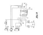
- FIGS. 16–18are circuit diagrams of the various lighting and switch components of first embodiment of the present invention.
- FIG. 19is an exploded view of a second embodiment of the present invention.
- FIG. 20is a plan view of a first polarizing filter of the second embodiment of the present invention showing the angle of polarization
- FIG. 21is a plan view of a second polarizing filter of the second embodiment of the present invention showing the out of phase polarization as compared to the first polarizing filter;
- FIG. 22is a top plan view of the lens assembly of the second embodiment of the present invention.
- FIG. 23is a cross-sectional view of the lens assembly along the A—A axis as shown in FIG. 22 ;
- FIG. 24is a cross-sectional view of the lens assembly along the A—A axis as shown in FIG. 22 with the spacer extended;
- FIG. 25is a perspective view of the lens assembly of the device of the second embodiment.
- FIG. 26is a perspective view of the lens assembly of the device of the second embodiment, with the spacer extended.
- FIG. 27is an exploded view of the lens assembly as shown in FIGS. 25–26 .
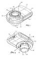
- FIGS. 1 and 2there are shown top and bottom perspective views, respectively, of the dermoscopy epiluminescence device 12 of the present invention.
- the device 12is lightweight and compact.
- the outer structure of the device 12can be utilized in association with the first embodiment ( FIGS. 9–18 ), the second embodiment ( FIGS. 19–27 ).
- the exterior appearance of the device for each of the first and second embodimentsis identical as shown in FIGS. 1 through 8 .
- the device 12is shown with a housing 14 that encases the working components of the device.
- the housing 14is formed of assembled pieces of injection molded polycarbonate and polyurethane. It will be recognized by one skilled in the art that the housing 14 can be formed form other suitable rigid lightweight material, including, but not limited to plastic, composite materials, fiberglass, aluminum, PVC, acetate and or lexan.
- a distal viewing port 16includes a lens retainer 18 for securing the lens and other internal components within the housing 14 .
- the distal viewing port 16is visually connected with the proximal viewing port 20 creating a line of sight through the housing 14 through lens 22 and polarizing filters (not shown).
- the view corridor through ports 16 and 20allows a user to view with the skin with a naked eye to view subject skin placed below proximal viewing port 20 .
- a lens tube 24secures the lens 22 and the entire lens assembly (not shown) within the housing 14 .
- the exposed rim of the lens tube 24includes threads (not shown) for engaging a standard cameral lens or a lens adaptor.
- the devicemay be securely affixed to a camera, and the cameral can capture images through the corridor formed by the ports 16 and 20 .
- a circular dial 26is exposed and is accessible about the perimeter of the distal viewing port 16 .
- the dialmay be manually rotated to effect a rotation of a spacer assembly (not shown) to extend or retract the spacer 28 .
- a spacer assembly(not shown) to extend or retract the spacer 28 .
- the spacer 28With the spacer 28 retracted, the user can effect a dry examination of the skin. With the spacer 28 extended, a user can complete a direct contact skin examination, typically employing oil emersion.
- the spacer 28includes a circular sidewall 30 that is retracted within the device when not in use, but extends outwardly and locks into place when extended.
- the sidewalls 30support a glass faceplate 32 .
- the glass faceplate 32contacts the skin to be examined.
- the glass faceplate 32also incorporates a scale 34 to provide the user with information regarding size of a lesion, blood vessel or other object to be viewed.
- the face plate 32is removable from the spacer 28 .
- the sidewalls 30 of the spacer 28includes a plurality of openings to allow light projected from the illumination sources (not shown) to light the area to be examined.
- Status LEDs 36provide the user with information about the light set being used or the relative intensity of the lights.
- Side switches 38 and 40provide the means to operate different sets of illumination sources (not shown) and to activate and deactivate light circuits.
- a power port 42is provided as a means of powering the device or recharging on-board batteries (not shown).
- a USB portis provided as means of powering the device.
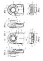
- the device of a first embodiment of the present inventionis shown.
- the device 12is shown from a bottom perspective exploded view
- the device 12is shown from a top perspective exploded view
- the housing 14is formed from top housing component 14 a and bottom housing component 14 b . Both components 14 a and 14 b include apertures for receiving a lens assembly 50 , and accommodating a lighting array 46 .
- the lighting arraycomprises a ring of LEDs affixed to an circuit board 48 .
- the circuit board 48is secured within the housing 14 .
- the LEDscomprise four different colored sets of LEDs each on a different lighting circuit.
- the four colorscomprise White, UV/Blue (405 nm), green/yellow (565 nm) and orange/red (630 nm).
- Whiteis contemplated for normal epiluminescence imaging, U/Blue for ALA florescence and autoflouresence imaging an, green/yellow for superficial blood vessel imaging and orange/red for deeper blood vessel imaging.
- U/Bluefor ALA florescence
- 480 nm, 580 nm and/or 660 nmmay be used together or in combination with previously identified colors or in combination with colors not identified herein.
- Indicator LEDsprovide the user information about the set of LEDs operating.
- the LEDs of the lighting array 46are four different colors, eight of each color for a total of 32 LEDs.
- the LEDsare a repeating pattern of the four different colors, fore example, white, UV/blue, green-yellow and orange/red repeating around the perimeter, with all like colors interconnected on a single circuit.
- a userinitiates a switch to light all of one color, which would comprise eight LEDs.
- the usercan then immediately switch to a second colored set, and so forth.
- the usercan compare and contrast images by toggling between colors.
- the first embodimentcontemplates a repeating series of four different colored lights, it is also contemplated that other combinations and arrangements may be utilized.
- a battery 54is selectively removable from the device 12 and the battery 54 electrically contacts the electrical board 48 and provides power to the device 12 .
- the battery 54is Lithium rechargeable battery is contemplated with greater than 600 mAh capability.
- the battery 54is adapted for at least four hours of continuous use with 8 LEDs. A typical single lesion examination lasts one minute, and as such the battery life is expected to cover approximately 240 skin lesion examinations.
- Side switches 38 and 40also interconnect with the board 48 and provide a user with the ability to selective operate the LEDs. The selection of the color of the LEDs of the light array 46 is done by switch 38 and the selection of the brightness of illumination is controlled by the swith 40 . Power ON/OFF is controlled by depressing swich 40 .
- the lens 22 in the first embodimentis preferably a 25 mm diameter aspherical lens with a 10 ⁇ optical gain.
- the aspherical designminimizes distortions.
- the lensis optimized to allow both visual viewing and also allow attachment of a digital camera for capturing images.
- a lens retainer 18secures the lens 22 within the housing 14 .
- the first embodimentemploys a aspherical lens
- the lensmay be a single convex lens, a combination of two or more lenses, a double achromat lens, or a combination of double achromat lenses.
- the lensmay incorporate Hastings lenses.
- the lensesare coated with an antireflection coating may be used and may additionally include a color filter to selectively filter light passing through the lens.
- a lens assembly 50is held within the lens tube 24 .
- the lens tube 24is received within the spacer mover 52 .
- the spacer 28is received over the spacer mover 52 , such that the rotation of the spacer mover 52 within the housing 14 causes the spacer 28 to extend and retract. Rotation of the spacer mover 52 is manually operated by the dial 26 .
- a center polarizer 56is integrated with the lens assembly 50 , and provides polarization to the eye of the user (or to a camera lens).
- An outside ring polarizer 58provides polarization to of light from the lighting array 46 , and such ring polarizer 58 is 90 degrees out of phase with the center polarizer 5
- the center polarizer 56 and outer ring polarizer 58are composed of acrylic plastic with polarization material embedded within the polarizer. It is contemplated by the invention that the polarizers 56 and 58 may be constructed of glass, also with material embedded or coated on the glass. In addition, the polarizers 56 and 58 may be coated with a filter material that can selectively filter out some of the light frequencies emanating from the object.
- the secondary filter assemblymade of plastic or glass with the capability of filtering the light may be placed in the path of the lens 22 to filter out some of the light. 6 such that the light that reaches the eye of the user (or the camera lens) is cross-polarized. It is contemplated by the present invention that the center polarizer 56 and ring polarizer may be selectively removable, to aid in viewing certain oil immersion dermoscopy examinations. It is also contemplated that device of the present invention can be produced without any polarizing filters.
- the lens assembly 50combined with the spacer components to form the lens-spacer assembly 60 .
- the lens assemblycomprises a lens retainer 18 , to retain the lens 22 .
- a polarizer spacer 62is provided below the lens 22 .
- a center polarizer 56is placed over the circular polarizer spacer 62 .
- the lens assembly 50is placed within the lens sleeve 24 .
- an outside polarizer 58is provided to provide polarization to the lighting array 46 .
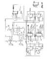
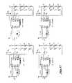
- FIGS. 16–18represent the lighting circuits used to power the lighting array 46 of the device 12 . It is contemplated that the lighting circuits may be comprised of any different number of circuit designs and the circuits represented in FIGS. 16–18 are one way of completing the function of the lighting circuits. Other schemes and designs are contemplated for controlling the lights and selection of color, including, but not limited to, remote control by a USB connector and an on-board microprocessor, control by embedded software in on-board electronics and computer controlled by the USB connector.
- FIGS. 19–27represent the second embodiment of the present invention and are referred hereto collectively.
- the design of the second embodimentis nearly identical to the first embodiment (and thus the description of common elements are not repeated herein) except for the following differences.
- the lighting array 64comprises two sets of LEDs, both sets white light. In this regard only two indicator LEDs 66 are required.
- the outside filter 68comprises two ring filters 70 and 72 , each filter 90 degrees out of phase with the other. In conformance with two sets of lights, the lighting circuits (not shown) are modified for the second embodiment.
- the top 70 and bottom 72 polarizersare 90 degrees out of phase.
- the bottom 72 polarizeris in cross polarization with the center polarizer 56 and top polarizer 70 is in parallel polarization with the center polarizer 56 .
- the top 70 and bottom 72 polarizersare composed of acrylic plastic and include polarization at different angles.
- the polarizers 70 and 72may also be coated with a special material to filter out some of the light emanating from the LEDs, or alternatively the annular polarizer 70 and 72 may be sandwiched with a color filter acrylic material.
- the aperture of the polarizer 58is wide enough to permit a viewing corridor from the lens 22 through the housing 14 while allowing portions of the top 70 and bottom 72 polarizers to be exposed and to filter light emitting diodes inside the housing 20 .
- the diodesare preferably white high light output Indium Gallium Nitride LEDs, however any suitable lighting diodes are appropriate.
- the even diodesare on a single circuit and the odd diodes are on a separate single circuit.
- the LEDsare a standard white LED made with phosphorescence phosphors to create white light. It is additionally contemplated by the present invention that tricolored LEDs, with individual red, green and blue LEDs that can combine form white light may be utilized. It is contemplated by the present invention that the LEDs may have focusing lenses to concentrate the light into a smaller and tighter beam.
- the LEDsmay additionally be comprised of indium gallium arsenide material, or any other like semiconductor material.
- a switchmay initiates half of the every other light source, which are the eight even diodes and the switch also initiates the second light source, which are the other sixteen odd diodes. All 32 diodes of the array 46 may be simultaneously
- a first polarizer filter 70comprises a planar annular ring defining a generally circular center opening and an outer ring.
- the center opening of the annular ring of the first polarizer 70is positioned in alignment with the circular optical lens 22 to provide an unobstructed view of the skin through the lens 22 and the housing 14 .
- the outer ring of the first polarizer 70includes a plurality of openings sized and positioned to correspond to the diodes of the second illumination source (i.e. every other diode 58 of the second light circuit) such that light emitted from the diodes of the second illumination source passes through the openings unfiltered by the first polarizer 70 . Because there are no corresponding openings for the diodes of the first illumination source (i.e. every other diode on the first light circuit) light emitted from first source diodes is polarized by the outer ring of the first polarizer filter 50 .
- a second polarizer filter 72comprises a planar annular ring defining a generally circular center opening and an outer ring.
- the center opening of said annular ring of the second polarizer 72is positioned in alignment with the circular optical lens 22 to provide an unobstructed view of the skin through the lens 22 and housing 14 .
- the second polarizer 72is 90 degrees out of phase with the first polarizer 70 .
- the outer ring of the second polarizer 52like the first polarizer 50 , has a plurality of openings sized and positioned to correspond to the diodes of the first illumination source (i.e.
Landscapes
- Health & Medical Sciences (AREA)
- Life Sciences & Earth Sciences (AREA)
- Pathology (AREA)
- General Health & Medical Sciences (AREA)
- Physics & Mathematics (AREA)
- Animal Behavior & Ethology (AREA)
- Public Health (AREA)
- Biomedical Technology (AREA)
- Heart & Thoracic Surgery (AREA)
- Medical Informatics (AREA)
- Molecular Biology (AREA)
- Surgery (AREA)
- Biophysics (AREA)
- Veterinary Medicine (AREA)
- Engineering & Computer Science (AREA)
- Dermatology (AREA)
- Nuclear Medicine, Radiotherapy & Molecular Imaging (AREA)
- Chemical & Material Sciences (AREA)
- Analytical Chemistry (AREA)
- Biochemistry (AREA)
- General Physics & Mathematics (AREA)
- Immunology (AREA)
- Measuring And Recording Apparatus For Diagnosis (AREA)
- Measurement Of The Respiration, Hearing Ability, Form, And Blood Characteristics Of Living Organisms (AREA)
- Eyeglasses (AREA)
Abstract
Description
Claims (24)
Priority Applications (1)
| Application Number | Priority Date | Filing Date | Title |
|---|---|---|---|
| US11/361,432US7167244B2 (en) | 2003-03-07 | 2006-02-24 | Dermoscopy epiluminescence device employing multiple color illumination sources |
Applications Claiming Priority (3)
| Application Number | Priority Date | Filing Date | Title |
|---|---|---|---|
| US10/384,110US7006223B2 (en) | 2003-03-07 | 2003-03-07 | Dermoscopy epiluminescence device employing cross and parallel polarization |
| US10/773,003US7027153B2 (en) | 2003-03-07 | 2004-02-05 | Dermoscopy epiluminescence device employing multiple color illumination sources |
| US11/361,432US7167244B2 (en) | 2003-03-07 | 2006-02-24 | Dermoscopy epiluminescence device employing multiple color illumination sources |
Related Parent Applications (1)
| Application Number | Title | Priority Date | Filing Date |
|---|---|---|---|
| US10/773,003ContinuationUS7027153B2 (en) | 2003-03-07 | 2004-02-05 | Dermoscopy epiluminescence device employing multiple color illumination sources |
Publications (2)
| Publication Number | Publication Date |
|---|---|
| US20060139640A1 US20060139640A1 (en) | 2006-06-29 |
| US7167244B2true US7167244B2 (en) | 2007-01-23 |
Family
ID=32927195
Family Applications (4)
| Application Number | Title | Priority Date | Filing Date |
|---|---|---|---|
| US10/384,110Expired - LifetimeUS7006223B2 (en) | 2003-03-07 | 2003-03-07 | Dermoscopy epiluminescence device employing cross and parallel polarization |
| US10/773,003Expired - LifetimeUS7027153B2 (en) | 2003-03-07 | 2004-02-05 | Dermoscopy epiluminescence device employing multiple color illumination sources |
| US11/345,142Expired - LifetimeUS7167243B2 (en) | 2003-03-07 | 2006-02-01 | Dermoscopy epiluminescence device employing cross and parallel polarization |
| US11/361,432Expired - LifetimeUS7167244B2 (en) | 2003-03-07 | 2006-02-24 | Dermoscopy epiluminescence device employing multiple color illumination sources |
Family Applications Before (3)
| Application Number | Title | Priority Date | Filing Date |
|---|---|---|---|
| US10/384,110Expired - LifetimeUS7006223B2 (en) | 2003-03-07 | 2003-03-07 | Dermoscopy epiluminescence device employing cross and parallel polarization |
| US10/773,003Expired - LifetimeUS7027153B2 (en) | 2003-03-07 | 2004-02-05 | Dermoscopy epiluminescence device employing multiple color illumination sources |
| US11/345,142Expired - LifetimeUS7167243B2 (en) | 2003-03-07 | 2006-02-01 | Dermoscopy epiluminescence device employing cross and parallel polarization |
Country Status (2)
| Country | Link |
|---|---|
| US (4) | US7006223B2 (en) |
| WO (1) | WO2004080525A2 (en) |
Cited By (28)
| Publication number | Priority date | Publication date | Assignee | Title |
|---|---|---|---|---|
| US20100106024A1 (en)* | 2008-10-28 | 2010-04-29 | Miranda Aref Farage | Method for diagnosing vulvovaginal disorders |
| US20100234737A1 (en)* | 2009-03-12 | 2010-09-16 | Miranda Aref Farage | Method for assessing skin irritation using infrared light |
| US20100249545A1 (en)* | 2009-03-24 | 2010-09-30 | International Business Machines Corporation | Remote delivery and monitoring of health care |
| US20120101342A1 (en)* | 2010-10-21 | 2012-04-26 | Duffy Thomas P | Pediatric tissue illuminator |
| US20130023773A1 (en)* | 2010-04-07 | 2013-01-24 | Stc. Unm | Apparatus and techniques of non-invasive analysis |
| US20130033855A1 (en)* | 2011-08-02 | 2013-02-07 | Cheng-Wei Su | Illuminating magnifying lens capable of focusing its light on objects |
| US20130071103A1 (en)* | 2011-09-21 | 2013-03-21 | Globalmedia Group, Llc | Dual polarizing hood |
| US20140012137A1 (en)* | 2012-07-06 | 2014-01-09 | Robert Rosen | Hand-Held Dual-Magnification Dermatoscope |
| US20140243685A1 (en)* | 2013-02-28 | 2014-08-28 | Canfield Scientific, Incorporated | Dermatoscope devices |
| WO2015013288A2 (en) | 2013-07-22 | 2015-01-29 | The Rockefeller University | System and method for optical detection of skin disease |
| US9042967B2 (en) | 2008-05-20 | 2015-05-26 | University Health Network | Device and method for wound imaging and monitoring |
| US20150323446A1 (en)* | 2012-11-30 | 2015-11-12 | Konica Minolta, Inc. | Reflection Properties Measuring Device and Manufacturing Method for Polarizing Plates Used in Same |
| US9458990B2 (en) | 2013-08-01 | 2016-10-04 | 3Gen, Inc. | Dermoscopy illumination device with selective polarization and orange light for enhanced viewing of pigmented tissue |
| US9775500B2 (en) | 2014-11-20 | 2017-10-03 | Globalmedia Group, Llc | Polarizing endoscopy system and method |
| US9955910B2 (en) | 2005-10-14 | 2018-05-01 | Aranz Healthcare Limited | Method of monitoring a surface feature and apparatus therefor |
| US10013527B2 (en) | 2016-05-02 | 2018-07-03 | Aranz Healthcare Limited | Automatically assessing an anatomical surface feature and securely managing information related to the same |
| US10036881B2 (en) | 2014-05-23 | 2018-07-31 | Pathonomic | Digital microscope system for a mobile device |
| US10438356B2 (en) | 2014-07-24 | 2019-10-08 | University Health Network | Collection and analysis of data for diagnostic purposes |
| US10441379B2 (en) | 2017-12-28 | 2019-10-15 | 3Gen, Inc. | Multipurpose medical illuminator with magnification |
| WO2020251938A1 (en) | 2019-06-09 | 2020-12-17 | Canfield Scientific, Incorporated | Hair analysis methods and apparatuses |
| US10874302B2 (en) | 2011-11-28 | 2020-12-29 | Aranz Healthcare Limited | Handheld skin measuring or monitoring device |
| EP3818926A1 (en) | 2019-11-11 | 2021-05-12 | 3Gen, Inc. | Medical illuminator with variable polarization |
| US11116407B2 (en) | 2016-11-17 | 2021-09-14 | Aranz Healthcare Limited | Anatomical surface assessment methods, devices and systems |
| US11134885B2 (en) | 2015-08-13 | 2021-10-05 | The Rockefeller University | Quantitative dermoscopic melanoma screening |
| US20220039657A1 (en)* | 2018-05-02 | 2022-02-10 | Canfield Scientific, Incorporated | Skin assessment using image fusion |
| WO2022133296A1 (en)* | 2020-12-18 | 2022-06-23 | The Johns Hopkins University | A compact capillaroscope for non-invasive blood analysis |
| US11903723B2 (en) | 2017-04-04 | 2024-02-20 | Aranz Healthcare Limited | Anatomical surface assessment methods, devices and systems |
| US12039726B2 (en) | 2019-05-20 | 2024-07-16 | Aranz Healthcare Limited | Automated or partially automated anatomical surface assessment methods, devices and systems |
Families Citing this family (113)
| Publication number | Priority date | Publication date | Assignee | Title |
|---|---|---|---|---|
| US6517532B1 (en) | 1997-05-15 | 2003-02-11 | Palomar Medical Technologies, Inc. | Light energy delivery head |
| US8182473B2 (en) | 1999-01-08 | 2012-05-22 | Palomar Medical Technologies | Cooling system for a photocosmetic device |
| US20060149343A1 (en)* | 1996-12-02 | 2006-07-06 | Palomar Medical Technologies, Inc. | Cooling system for a photocosmetic device |
| ES2226133T3 (en) | 1997-05-15 | 2005-03-16 | Palomar Medical Technologies, Inc. | DERMATOLOGICAL TREATMENT DEVICE. |
| ES2245506T3 (en) | 1998-03-12 | 2006-01-01 | Palomar Medical Technologies, Inc. | ELECTROMAGNETIC RADIATION APPLICATION SYSTEM ON SKIN. |
| US20080172047A1 (en)* | 2000-12-28 | 2008-07-17 | Palomar Medical Technologies, Inc. | Methods And Devices For Fractional Ablation Of Tissue |
| EP1700573A3 (en)* | 2000-12-28 | 2010-12-01 | Palomar Medical Technologies, Inc. | Apparatus for therapeutic EMR treatment of the skin |
| US6888319B2 (en)* | 2001-03-01 | 2005-05-03 | Palomar Medical Technologies, Inc. | Flashlamp drive circuit |
| WO2002069825A2 (en)* | 2001-03-02 | 2002-09-12 | Palomar Medical Technologies, Inc. | Apparatus and method for photocosmetic and photodermatological treatment |
| WO2003096387A2 (en) | 2002-05-08 | 2003-11-20 | Phoseon Technology, Inc. | High efficiency solid-state light source and methods of use and manufacture |
| WO2004000098A2 (en) | 2002-06-19 | 2003-12-31 | Palomar Medical Technologies, Inc. | Method and apparatus for treatment of cutaneous and subcutaneous conditions |
| US20040062056A1 (en)* | 2002-09-26 | 2004-04-01 | Heine Optotechnik Gmbh & Co. Kg | Dermatoscope |
| EP2522294A2 (en) | 2002-10-23 | 2012-11-14 | Palomar Medical Technologies, Inc. | Phototreatment device for use with coolants and topical substances |
| AU2003301111A1 (en)* | 2002-12-20 | 2004-07-22 | Palomar Medical Technologies, Inc. | Apparatus for light treatment of acne and other disorders of follicles |
| US7006223B2 (en)* | 2003-03-07 | 2006-02-28 | 3Gen, Llc. | Dermoscopy epiluminescence device employing cross and parallel polarization |
| JP3954533B2 (en)* | 2003-06-17 | 2007-08-08 | 株式会社モリテックス | Skin observation device |
| US7309335B2 (en)* | 2003-12-31 | 2007-12-18 | Palomar Medical Technologies, Inc. | Dermatological treatment with visualization |
| US6979099B2 (en)* | 2004-02-12 | 2005-12-27 | Brookstone Purchasing, Inc. | Portable lighting device with multi-activation switch |
| EP2301471A1 (en) | 2004-04-01 | 2011-03-30 | The General Hospital Corporation | Method and apparatus for dermatological treatment and tissue reshaping |
| JP2008500846A (en)* | 2004-04-09 | 2008-01-17 | パロマー メディカル テクノロジーズ,インク. | Method and product for making a grid of EMR-treated isolated points in tissue and use thereof |
| US7415143B2 (en)* | 2004-04-13 | 2008-08-19 | Duke University | Methods and systems for the detection of malignant melanoma |
| KR101122029B1 (en)* | 2004-04-15 | 2012-03-09 | 가부시키가이샤 모리텍스 | Face imaging device |
| US7431695B1 (en)* | 2004-08-03 | 2008-10-07 | Venoscope, Llc | Neonatal transilluminator apparatus |
| EP1866954B1 (en) | 2004-12-30 | 2016-04-20 | Phoseon Technology, Inc. | Methods and systems relating to light sources for use in industrial processes |
| FR2881225B1 (en)* | 2005-01-21 | 2007-10-26 | Cypher Science Sarl | PORTABLE DETECTION APPARATUS FOR FIELD DETECTION OF FLUORESCENT-MARKING ELEMENTS |
| US9049412B2 (en)* | 2005-03-30 | 2015-06-02 | Tte Technology, Inc. | System and method for projecting video onto a screen |
| US7856985B2 (en) | 2005-04-22 | 2010-12-28 | Cynosure, Inc. | Method of treatment body tissue using a non-uniform laser beam |
| CN100413467C (en)* | 2005-05-08 | 2008-08-27 | 上海希格玛高技术有限公司 | Dermatology Diagnostic Device |
| US7689016B2 (en)* | 2005-05-27 | 2010-03-30 | Stoecker & Associates, A Subsidiary Of The Dermatology Center, Llc | Automatic detection of critical dermoscopy features for malignant melanoma diagnosis |
| US20070002479A1 (en)* | 2005-06-29 | 2007-01-04 | Johnson & Johnson Consumer Companies, Inc. | Apparatus and method for viewing the skin |
| WO2007019536A2 (en)* | 2005-08-08 | 2007-02-15 | Palomar Medical Technologies, Inc. | Eye-safe photocosmetic device |
| CA2618706C (en) | 2005-08-12 | 2018-01-02 | Rick B. Yeager | System and method for medical monitoring and treatment through cosmetic monitoring and treatment |
| CN101309631A (en) | 2005-09-15 | 2008-11-19 | 帕洛玛医疗技术公司 | Skin optical characterization device |
| US8032205B2 (en)* | 2005-09-16 | 2011-10-04 | Mullani Nizar A | Transilluminator light shield |
| US7874698B2 (en)* | 2005-09-16 | 2011-01-25 | Mullani Nizar A | Transillumination having orange color light |
| US20070153372A1 (en)* | 2006-01-03 | 2007-07-05 | Physical Sciences, Inc. | Fluorescence illumination method and apparatus for stereomicroscopes |
| WO2007117580A2 (en)* | 2006-04-06 | 2007-10-18 | Palomar Medical Technologies, Inc. | Apparatus and method for skin treatment with compression and decompression |
| US7841751B2 (en)* | 2006-04-28 | 2010-11-30 | Mulani Nizar A | Pediatric adapter for transillumination |
| US7901096B2 (en)* | 2006-07-17 | 2011-03-08 | Dorsey Metrology International | Illumination for projecting an image |
| US7586957B2 (en) | 2006-08-02 | 2009-09-08 | Cynosure, Inc | Picosecond laser apparatus and methods for its operation and use |
| US8942775B2 (en)* | 2006-08-14 | 2015-01-27 | Tcms Transparent Beauty Llc | Handheld apparatus and method for the automated application of cosmetics and other substances |
| US8184901B2 (en) | 2007-02-12 | 2012-05-22 | Tcms Transparent Beauty Llc | System and method for applying a reflectance modifying agent to change a person's appearance based on a digital image |
| US7764303B2 (en)* | 2006-10-02 | 2010-07-27 | Johnson & Johnson Consumer Companies, Inc. | Imaging apparatus and methods for capturing and analyzing digital images of the skin |
| US7558416B2 (en)* | 2006-10-02 | 2009-07-07 | Johnson & Johnson Consumer Companies, Inc. | Apparatus and method for measuring photodamage to skin |
| US20100185064A1 (en)* | 2007-01-05 | 2010-07-22 | Jadran Bandic | Skin analysis methods |
| EP2099363A4 (en)* | 2007-01-05 | 2012-01-04 | Myskin Inc | System, device and method for dermal imaging |
| US20090245603A1 (en)* | 2007-01-05 | 2009-10-01 | Djuro Koruga | System and method for analysis of light-matter interaction based on spectral convolution |
| US20080186591A1 (en)* | 2007-02-01 | 2008-08-07 | Palomar Medical Technologies, Inc. | Dermatological device having a zoom lens system |
| RU2367340C2 (en)* | 2007-02-12 | 2009-09-20 | Закрытое акционерное общество "Инженерное предприятие "Поток" | Capillary blood flowrecorder |
| CN101641161B (en)* | 2007-02-12 | 2012-04-18 | Tcms剔透美丽有限责任公司 | System and method for applying agent electrostatically to human skin |
| US8213695B2 (en)* | 2007-03-07 | 2012-07-03 | University Of Houston | Device and software for screening the skin |
| US10092082B2 (en)* | 2007-05-29 | 2018-10-09 | Tcms Transparent Beauty Llc | Apparatus and method for the precision application of cosmetics |
| DE102007034936A1 (en) | 2007-07-23 | 2009-01-29 | Friedrich-Schiller-Universität Jena | Weak fluorescent area recognizing device for recognition of pathological changes of e.g. skin, has portion of radiation defined such that intensity of radiation and intensity of fluorescence led to signals with imaging detection system |
| US20090118600A1 (en)* | 2007-11-02 | 2009-05-07 | Ortiz Joseph L | Method and apparatus for skin documentation and analysis |
| DE102009011787B4 (en)* | 2008-03-11 | 2011-06-01 | Vision & Control Gmbh | Coaxial incident light illumination |
| USD601697S1 (en)* | 2008-03-28 | 2009-10-06 | Reliant Technologies, Inc. | Handpiece for a dermatological optical delivery system |
| US9572494B2 (en)* | 2008-08-12 | 2017-02-21 | New Jersy Institute of Technology | Method and apparatus for multi-spectral imaging and analysis of skin lesions and biological tissues |
| USD646396S1 (en)* | 2008-12-19 | 2011-10-04 | Panasonic Electric Works Co., Ltd. | Light irradiation facial apparatus |
| USD621949S1 (en)* | 2008-12-19 | 2010-08-17 | Panasonic Electric Works Co., Ltd | Light irradiation facial apparatus |
| USD621950S1 (en)* | 2008-12-19 | 2010-08-17 | Panasonic Electric Works Co., Ltd. | Light irradiation facial apparatus |
| EP2223650A1 (en) | 2009-02-25 | 2010-09-01 | The Provost, Fellows and Scholars of the College of the Holy and Undivided Trinity of Queen Elizabeth near Dublin | Method and apparatus for imaging tissue topography |
| TWM366991U (en)* | 2009-04-06 | 2009-10-21 | Tsu-I Hsia | Structure improvement of hand-held intravenous injection imaging transilluminator |
| US9919168B2 (en) | 2009-07-23 | 2018-03-20 | Palomar Medical Technologies, Inc. | Method for improvement of cellulite appearance |
| TWM385006U (en)* | 2010-01-22 | 2010-07-21 | Lumos Technology Co Ltd | Microscopic detection device for fluorescent testing |
| EP2538841A2 (en) | 2010-02-26 | 2013-01-02 | Myskin, Inc. | Analytic methods of tissue evaluation |
| CN102240205A (en)* | 2010-05-14 | 2011-11-16 | 北京大学 | Polarized skin lens |
| DE102010021534A1 (en)* | 2010-05-19 | 2011-11-24 | Eberhard-Karls-Universität Tübingen Universitätsklinikum | Direct investigation of biological material ex vivo |
| US10955109B1 (en) | 2010-07-07 | 2021-03-23 | Courtney Joseph Monzyk | Portable lighting device |
| US9001326B2 (en) | 2011-12-13 | 2015-04-07 | Welch Allyn, Inc. | Method and apparatus for observing subsurfaces of a target material |
| JP2013188341A (en)* | 2012-03-14 | 2013-09-26 | Sony Corp | Image processing device, image processing method, and program |
| EP2839552A4 (en) | 2012-04-18 | 2015-12-30 | Cynosure Inc | PICOSECOND LASER APPARATUS AND METHOD OF PROCESSING TARGET TISSUES USING THE SAME |
| WO2013191665A2 (en) | 2012-06-21 | 2013-12-27 | Grimed Saglik Hizmetleri Ve Bilgisayar Urunleri Sanayi Ticaret Limited Sirketi | A mobile microscopy device being able to take images in different wavelengths (multispectral) |
| US9480529B2 (en)* | 2012-06-22 | 2016-11-01 | S & Y Enterprises Llc | Aesthetic treatment device and method |
| US9364684B2 (en) | 2012-06-22 | 2016-06-14 | S & Y Enterprises Llc | Aesthetic treatment device and method |
| DE202012008449U1 (en) | 2012-09-04 | 2012-09-20 | Heine Optotechnik Gmbh & Co Kg | Spacer attachment for a dermatoscope |
| USD705422S1 (en)* | 2012-10-26 | 2014-05-20 | 3M Innovative Properties Company | Microneedle applicator |
| USD693921S1 (en)* | 2012-10-26 | 2013-11-19 | 3M Innovative Properties Company | Microneedle applicator |
| DE102012221527A1 (en) | 2012-11-26 | 2014-06-12 | Heine Optotechnik Gmbh & Co Kg | Optical diagnostic tool, particularly dermatoscope for investigating examination area of patient, has first polarizing filter unit downstream in illumination beam path of illumination unit in illuminating direction |
| KR20140089129A (en)* | 2013-01-04 | 2014-07-14 | 삼성전자주식회사 | Optical zoom probe |
| US10285757B2 (en) | 2013-03-15 | 2019-05-14 | Cynosure, Llc | Picosecond optical radiation systems and methods of use |
| CA2918383A1 (en)* | 2013-07-15 | 2015-01-22 | Daniel L. Farkas | Disposable calibration end-cap for use in a dermoscope and other optical instruments |
| US20180234598A9 (en)* | 2013-08-07 | 2018-08-16 | Naturalpoint, Inc. | Motion Capture Camera with Illuminated Status Ring |
| CN105193381A (en)* | 2014-06-05 | 2015-12-30 | 苏州速迈医疗设备有限公司 | Dermatoscope |
| CN105125170A (en) | 2014-06-05 | 2015-12-09 | 苏州速迈医疗设备有限公司 | Observation cover of dermatoscope |
| US10368795B2 (en)* | 2014-06-30 | 2019-08-06 | Canfield Scientific, Incorporated | Acne imaging methods and apparatus |
| CN104068830B (en)* | 2014-07-24 | 2017-02-01 | 天津市鹰泰利安康医疗科技有限责任公司 | Double-light vessel imaging device |
| CN104199184A (en)* | 2014-08-18 | 2014-12-10 | 苏州倍力信电气有限公司 | Novel digital handheld memory magnifier |
| US10244944B2 (en)* | 2015-02-20 | 2019-04-02 | Translite, Llc | Vein transillumination device using orange and red light with a white exam light |
| HK1200267A2 (en)* | 2015-03-11 | 2015-07-31 | Schileo Alberto | Lighting attachment |
| CN107222687B (en)* | 2016-03-21 | 2020-12-18 | 联想(北京)有限公司 | Electronic device, control method and control device thereof |
| FR3051341B1 (en) | 2016-05-18 | 2018-06-01 | Universite De Lorraine | MEDICAL WIRELESS DEVICE FOR ACQUIRING SKIN VIDEOS BIMODALITY WITH LIGHT CONTROL |
| KR101785056B1 (en)* | 2016-07-08 | 2017-11-06 | 주식회사 일루코 | Dermatoscope devices |
| JP6888565B2 (en) | 2017-04-04 | 2021-06-16 | カシオ計算機株式会社 | Dermoscopy imaging device |
| TWI639137B (en)* | 2017-04-27 | 2018-10-21 | 立特克科技股份有限公司 | Skin detecting device and detecting method thereof |
| CN108784647B (en)* | 2017-04-27 | 2021-07-27 | 立特克科技股份有限公司 | Skin detection device and detection method thereof |
| US10675823B2 (en) | 2017-09-11 | 2020-06-09 | Lumenflow | Triplet lens method of manufacture |
| KR101821993B1 (en) | 2017-09-28 | 2018-03-08 | 주식회사 일루코 | Dermatoscope devices |
| WO2019074298A1 (en)* | 2017-10-11 | 2019-04-18 | 주식회사 일루코 | Optical skin diagonosis device, light emitting unit provided in dermatoscope device, and dermatoscope device comprising same |
| KR102070014B1 (en)* | 2017-10-11 | 2020-01-29 | 주식회사 일루코 | Light emitting unit mounted on dermatoscope devices and dermatoscope devices comprising the same |
| WO2019131586A1 (en) | 2017-12-27 | 2019-07-04 | カシオ計算機株式会社 | Image capture device and image capture method |
| JP7000933B2 (en)* | 2017-12-27 | 2022-01-19 | カシオ計算機株式会社 | Imaging device and imaging method |
| EP3505048A1 (en)* | 2017-12-28 | 2019-07-03 | Koninklijke Philips N.V. | Optical skin sensor using optimal spectral bands to minimize the effect of probe pressure |
| WO2019165426A1 (en) | 2018-02-26 | 2019-08-29 | Cynosure, Inc. | Q-switched cavity dumped sub-nanosecond laser |
| JP7106976B2 (en)* | 2018-05-11 | 2022-07-27 | カシオ計算機株式会社 | Imaging device |
| CN108403089A (en)* | 2018-05-15 | 2018-08-17 | 苏州国科盈睿医疗科技有限公司 | A kind of hand-held dermoscopy |
| US10575623B2 (en)* | 2018-06-29 | 2020-03-03 | Sephora USA, Inc. | Color capture system and device |
| CN109549631A (en)* | 2018-12-13 | 2019-04-02 | 福建师范大学 | A kind of Multifunctional LED light source for skin fluorescence detection |
| US20200367803A1 (en)* | 2019-04-24 | 2020-11-26 | Alexander M. WITKOWSKI | Dermatoscope attachment for mobile devices |
| US10989370B2 (en)* | 2019-04-26 | 2021-04-27 | Denise Longarzo | Decorative bi-directional portable lighting device |
| US12144586B2 (en)* | 2019-09-02 | 2024-11-19 | Canfield Scientific, Incorporated | Variable polarization and skin depth analysis methods and apparatuses |
| JP6915710B1 (en)* | 2020-02-03 | 2021-08-04 | カシオ計算機株式会社 | Conversion lens mounting structure and inspection equipment |
| WO2022086938A1 (en)* | 2020-10-20 | 2022-04-28 | Canfield Scientific, Incorporated | Acne severity grading methods and apparatuses |
| DE102023103906A1 (en)* | 2023-02-16 | 2024-08-22 | Heine Optotechnik Gmbh & Co. Kg | Optical medical examination device |
Citations (29)
| Publication number | Priority date | Publication date | Assignee | Title |
|---|---|---|---|---|
| US2120365A (en) | 1936-12-21 | 1938-06-14 | Sheet Polarizer Company Inc | New and improved viewing device for use in the examination of photoelastic effects |
| US2866375A (en) | 1953-10-12 | 1958-12-30 | Bowater Res & Dev Co Ltd | Gloss meter |
| US2947212A (en) | 1956-04-30 | 1960-08-02 | American Brass Co | Method of detecting surface conditions of sheet metal |
| US3062087A (en) | 1956-04-09 | 1962-11-06 | Budd Co | Apparatus for investigating polarized light phenomena |
| US3711182A (en)* | 1971-05-17 | 1973-01-16 | J Jasgur | Glareless mirror using relatively rotatable polarizers |
| US4007979A (en) | 1975-04-18 | 1977-02-15 | Mcdonnell Douglas Corporation | Reflection elimination system |
| US4398541A (en) | 1978-05-25 | 1983-08-16 | Xienta, Inc. | Method and apparatus for measuring moisture content of skin |
| US4773097A (en) | 1984-05-31 | 1988-09-20 | Omron Tateisi Electronics Co. | Image analyzing apparatus |
| US4846184A (en) | 1985-04-09 | 1989-07-11 | Sanofi | Skin reflectance measuring apparatus |
| US4957368A (en) | 1989-03-16 | 1990-09-18 | Photoacoustic Technology, Inc. | Apparatus and process for performing ellipsometric measurements of surfaces |
| US4998818A (en) | 1989-08-23 | 1991-03-12 | Welch Allyn, Inc. | Ophthalmoscope with linear polarizer |
| US5146923A (en) | 1986-12-18 | 1992-09-15 | Dhawan Atam P | Apparatus and method for skin lesion examination |
| US5198875A (en) | 1990-08-16 | 1993-03-30 | L'oreal | Device designed to assess the brightness of a surface more particularly of the skin |
| US5343536A (en) | 1992-11-20 | 1994-08-30 | Amway Corporation | Method of using image analysis under cross-polarized light to evaluate follicular biopsy slides |
| US5363854A (en) | 1990-08-24 | 1994-11-15 | U.S. Philips Corporation | Method of detecting anomalies of the skin, more particularly melanomae, and apparatus for carrying out the method |
| US5690417A (en) | 1996-05-13 | 1997-11-25 | Optical Gaging Products, Inc. | Surface illuminator with means for adjusting orientation and inclination of incident illumination |
| US5742392A (en) | 1996-04-16 | 1998-04-21 | Seymour Light, Inc. | Polarized material inspection apparatus |
| US6032071A (en) | 1994-12-01 | 2000-02-29 | Norbert Artner | Skin examination device |
| US6069565A (en) | 1992-10-20 | 2000-05-30 | Rosemount Aerospace Inc. | System for detecting ice or snow on surface which specularly reflects light |
| US6081612A (en) | 1997-02-28 | 2000-06-27 | Electro Optical Sciences Inc. | Systems and methods for the multispectral imaging and characterization of skin tissue |
| US6118476A (en)* | 1998-04-21 | 2000-09-12 | Moritex Corporation | CCD Microscope |
| US6207136B1 (en) | 1997-03-11 | 2001-03-27 | Tokyo University Of Agriculture And Technology | Fluorescent imaging method of saccharide uptake activity of living tissue |
| US6384988B1 (en) | 1999-10-22 | 2002-05-07 | Lifatec Gmbh Faseroptik Und Optoelektronik | Illuminated optical enlargement device |
| US6483247B2 (en) | 2001-02-20 | 2002-11-19 | Syris Scientific, L.L.C. | Lighting apparatus and light control method |
| US20030026110A1 (en) | 2001-08-06 | 2003-02-06 | Moritex Corporation | Imaging apparatus |
| US20030045799A1 (en) | 2001-07-09 | 2003-03-06 | L'oreal | Device, system and method for observing a typological characteristic of the body |
| US6587711B1 (en) | 1999-07-22 | 2003-07-01 | The Research Foundation Of Cuny | Spectral polarizing tomographic dermatoscope |
| US7004599B2 (en)* | 2004-01-02 | 2006-02-28 | 3Gen, Llc. | Illuminated mirror employing cross and parallel polarization |
| US7006223B2 (en)* | 2003-03-07 | 2006-02-28 | 3Gen, Llc. | Dermoscopy epiluminescence device employing cross and parallel polarization |
- 2003
- 2003-03-07USUS10/384,110patent/US7006223B2/ennot_activeExpired - Lifetime
- 2004
- 2004-02-05USUS10/773,003patent/US7027153B2/ennot_activeExpired - Lifetime
- 2004-02-25WOPCT/US2004/005505patent/WO2004080525A2/enactiveApplication Filing
- 2006
- 2006-02-01USUS11/345,142patent/US7167243B2/ennot_activeExpired - Lifetime
- 2006-02-24USUS11/361,432patent/US7167244B2/ennot_activeExpired - Lifetime
Patent Citations (30)
| Publication number | Priority date | Publication date | Assignee | Title |
|---|---|---|---|---|
| US2120365A (en) | 1936-12-21 | 1938-06-14 | Sheet Polarizer Company Inc | New and improved viewing device for use in the examination of photoelastic effects |
| US2866375A (en) | 1953-10-12 | 1958-12-30 | Bowater Res & Dev Co Ltd | Gloss meter |
| US3062087A (en) | 1956-04-09 | 1962-11-06 | Budd Co | Apparatus for investigating polarized light phenomena |
| US2947212A (en) | 1956-04-30 | 1960-08-02 | American Brass Co | Method of detecting surface conditions of sheet metal |
| US3711182A (en)* | 1971-05-17 | 1973-01-16 | J Jasgur | Glareless mirror using relatively rotatable polarizers |
| US4007979A (en) | 1975-04-18 | 1977-02-15 | Mcdonnell Douglas Corporation | Reflection elimination system |
| US4398541A (en) | 1978-05-25 | 1983-08-16 | Xienta, Inc. | Method and apparatus for measuring moisture content of skin |
| US4773097A (en) | 1984-05-31 | 1988-09-20 | Omron Tateisi Electronics Co. | Image analyzing apparatus |
| US4846184A (en) | 1985-04-09 | 1989-07-11 | Sanofi | Skin reflectance measuring apparatus |
| US5146923A (en) | 1986-12-18 | 1992-09-15 | Dhawan Atam P | Apparatus and method for skin lesion examination |
| US4957368A (en) | 1989-03-16 | 1990-09-18 | Photoacoustic Technology, Inc. | Apparatus and process for performing ellipsometric measurements of surfaces |
| US4998818A (en) | 1989-08-23 | 1991-03-12 | Welch Allyn, Inc. | Ophthalmoscope with linear polarizer |
| US5198875A (en) | 1990-08-16 | 1993-03-30 | L'oreal | Device designed to assess the brightness of a surface more particularly of the skin |
| US5363854A (en) | 1990-08-24 | 1994-11-15 | U.S. Philips Corporation | Method of detecting anomalies of the skin, more particularly melanomae, and apparatus for carrying out the method |
| US6069565A (en) | 1992-10-20 | 2000-05-30 | Rosemount Aerospace Inc. | System for detecting ice or snow on surface which specularly reflects light |
| US5343536A (en) | 1992-11-20 | 1994-08-30 | Amway Corporation | Method of using image analysis under cross-polarized light to evaluate follicular biopsy slides |
| US6032071A (en) | 1994-12-01 | 2000-02-29 | Norbert Artner | Skin examination device |
| US5742392A (en) | 1996-04-16 | 1998-04-21 | Seymour Light, Inc. | Polarized material inspection apparatus |
| US5690417A (en) | 1996-05-13 | 1997-11-25 | Optical Gaging Products, Inc. | Surface illuminator with means for adjusting orientation and inclination of incident illumination |
| US6081612A (en) | 1997-02-28 | 2000-06-27 | Electro Optical Sciences Inc. | Systems and methods for the multispectral imaging and characterization of skin tissue |
| US6207136B1 (en) | 1997-03-11 | 2001-03-27 | Tokyo University Of Agriculture And Technology | Fluorescent imaging method of saccharide uptake activity of living tissue |
| US6118476A (en)* | 1998-04-21 | 2000-09-12 | Moritex Corporation | CCD Microscope |
| US6587711B1 (en) | 1999-07-22 | 2003-07-01 | The Research Foundation Of Cuny | Spectral polarizing tomographic dermatoscope |
| US6384988B1 (en) | 1999-10-22 | 2002-05-07 | Lifatec Gmbh Faseroptik Und Optoelektronik | Illuminated optical enlargement device |
| US6483247B2 (en) | 2001-02-20 | 2002-11-19 | Syris Scientific, L.L.C. | Lighting apparatus and light control method |
| US20030045799A1 (en) | 2001-07-09 | 2003-03-06 | L'oreal | Device, system and method for observing a typological characteristic of the body |
| US20030026110A1 (en) | 2001-08-06 | 2003-02-06 | Moritex Corporation | Imaging apparatus |
| US7006223B2 (en)* | 2003-03-07 | 2006-02-28 | 3Gen, Llc. | Dermoscopy epiluminescence device employing cross and parallel polarization |
| US7027153B2 (en)* | 2003-03-07 | 2006-04-11 | 3 Gen, Llc. | Dermoscopy epiluminescence device employing multiple color illumination sources |
| US7004599B2 (en)* | 2004-01-02 | 2006-02-28 | 3Gen, Llc. | Illuminated mirror employing cross and parallel polarization |
Non-Patent Citations (4)
| Title |
|---|
| (Brochure) 3gen, LLC., "3gen the Beauty of Evolutionary Innovation," 3 pages (trifold), Feb. 15, 2002 (Estimated publication date). |
| (Brochure) 3gen, LLC., "First in Pocket Epiluminescence Microscopy," 1 page, Mar. 15, 2001 (Estimated publication date). |
| (Internet Literature) www.syrissscientific.com, "Technical", 1 page, (Unknown publication date). |
| Keshen R. Mathura et al., "Comparison of OPS imaging and conventional capillary microscopy to study the human microcirculation," p. 74-78 The American Physiological Society, 2001. |
Cited By (62)
| Publication number | Priority date | Publication date | Assignee | Title |
|---|---|---|---|---|
| US9955910B2 (en) | 2005-10-14 | 2018-05-01 | Aranz Healthcare Limited | Method of monitoring a surface feature and apparatus therefor |
| US10827970B2 (en) | 2005-10-14 | 2020-11-10 | Aranz Healthcare Limited | Method of monitoring a surface feature and apparatus therefor |
| US12226186B2 (en) | 2008-05-20 | 2025-02-18 | University Health Network | Devices, methods, and systems with spectral filtering for detecting wound and identifying bacteria based on fluorescence signature |
| US11154198B2 (en) | 2008-05-20 | 2021-10-26 | University Health Network | Method and system for imaging and collection of data for diagnostic purposes |
| US9042967B2 (en) | 2008-05-20 | 2015-05-26 | University Health Network | Device and method for wound imaging and monitoring |
| US12251191B2 (en) | 2008-05-20 | 2025-03-18 | University Health Network | Diagnostic method and system with optical and temperature sensors for imaging and mapping fluorescence intensities of tissue |
| US11375898B2 (en) | 2008-05-20 | 2022-07-05 | University Health Network | Method and system with spectral filtering and thermal mapping for imaging and collection of data for diagnostic purposes from bacteria |
| US11284800B2 (en) | 2008-05-20 | 2022-03-29 | University Health Network | Devices, methods, and systems for fluorescence-based endoscopic imaging and collection of data with optical filters with corresponding discrete spectral bandwidth |
| US20100106024A1 (en)* | 2008-10-28 | 2010-04-29 | Miranda Aref Farage | Method for diagnosing vulvovaginal disorders |
| US9532717B2 (en) | 2008-10-28 | 2017-01-03 | The Procter & Gamble Company | Method for diagnosing vulvovaginal disorders |
| US20100234737A1 (en)* | 2009-03-12 | 2010-09-16 | Miranda Aref Farage | Method for assessing skin irritation using infrared light |
| US20100249545A1 (en)* | 2009-03-24 | 2010-09-30 | International Business Machines Corporation | Remote delivery and monitoring of health care |
| US9844333B2 (en) | 2009-03-24 | 2017-12-19 | International Business Machines Corporation | Remote delivery and monitoring of health care |
| US11141099B2 (en) | 2009-03-24 | 2021-10-12 | International Business Machines Corporation | Remote delivery and monitoring of health care |
| US9999385B2 (en) | 2009-03-24 | 2018-06-19 | International Business Machines Corporation | Remote delivery and monitoring of health care |
| US10813582B2 (en) | 2009-03-24 | 2020-10-27 | International Business Machines Corporation | Remote delivery and monitoring of health care |
| US20130023773A1 (en)* | 2010-04-07 | 2013-01-24 | Stc. Unm | Apparatus and techniques of non-invasive analysis |
| US20120101342A1 (en)* | 2010-10-21 | 2012-04-26 | Duffy Thomas P | Pediatric tissue illuminator |
| US20130033855A1 (en)* | 2011-08-02 | 2013-02-07 | Cheng-Wei Su | Illuminating magnifying lens capable of focusing its light on objects |
| US8641249B2 (en) | 2011-08-02 | 2014-02-04 | Cheng-Wei Su | Illuminating magnifying lens capable of focusing its light on objects |
| US8449155B2 (en)* | 2011-08-02 | 2013-05-28 | Cheng-Wei Su | Illuminating magnifying lens capable of focusing its light on objects |
| US8774619B2 (en)* | 2011-09-21 | 2014-07-08 | Globalmedia Group, Llc | Dual polarizing hood |
| US20130071103A1 (en)* | 2011-09-21 | 2013-03-21 | Globalmedia Group, Llc | Dual polarizing hood |
| US8588605B2 (en)* | 2011-09-21 | 2013-11-19 | Globalmedia Group, Llc | Dual polarizing hood |
| US11850025B2 (en) | 2011-11-28 | 2023-12-26 | Aranz Healthcare Limited | Handheld skin measuring or monitoring device |
| US10874302B2 (en) | 2011-11-28 | 2020-12-29 | Aranz Healthcare Limited | Handheld skin measuring or monitoring device |
| US20140012137A1 (en)* | 2012-07-06 | 2014-01-09 | Robert Rosen | Hand-Held Dual-Magnification Dermatoscope |
| US20150323446A1 (en)* | 2012-11-30 | 2015-11-12 | Konica Minolta, Inc. | Reflection Properties Measuring Device and Manufacturing Method for Polarizing Plates Used in Same |
| US10012583B2 (en)* | 2012-11-30 | 2018-07-03 | Konica Minolta, Inc. | Reflection properties measuring device and manufacturing method for polarizing plates used in same |
| US20140243685A1 (en)* | 2013-02-28 | 2014-08-28 | Canfield Scientific, Incorporated | Dermatoscope devices |
| US10617305B2 (en)* | 2013-02-28 | 2020-04-14 | Canfield Scientific, Incorporated | Dermatoscope devices |
| US11931164B2 (en) | 2013-07-22 | 2024-03-19 | The Rockefeller University | System and method for optical detection of skin disease |
| WO2015013288A2 (en) | 2013-07-22 | 2015-01-29 | The Rockefeller University | System and method for optical detection of skin disease |
| US10307098B2 (en) | 2013-07-22 | 2019-06-04 | The Rockefeller University | System and method for optical detection of skin disease |
| US10182757B2 (en) | 2013-07-22 | 2019-01-22 | The Rockefeller University | System and method for optical detection of skin disease |
| US9458990B2 (en) | 2013-08-01 | 2016-10-04 | 3Gen, Inc. | Dermoscopy illumination device with selective polarization and orange light for enhanced viewing of pigmented tissue |
| US10036881B2 (en) | 2014-05-23 | 2018-07-31 | Pathonomic | Digital microscope system for a mobile device |
| US10438356B2 (en) | 2014-07-24 | 2019-10-08 | University Health Network | Collection and analysis of data for diagnostic purposes |
| US11676276B2 (en) | 2014-07-24 | 2023-06-13 | University Health Network | Collection and analysis of data for diagnostic purposes |
| US11954861B2 (en) | 2014-07-24 | 2024-04-09 | University Health Network | Systems, devices, and methods for visualization of tissue and collection and analysis of data regarding same |
| US11961236B2 (en) | 2014-07-24 | 2024-04-16 | University Health Network | Collection and analysis of data for diagnostic purposes |
| US12169935B2 (en) | 2014-07-24 | 2024-12-17 | University Health Network | Systems, devices, and methods for visualization of tissue and collection and analysis of data regarding same |
| US12387335B2 (en) | 2014-07-24 | 2025-08-12 | University Health Network | Systems, devices, and methods for visualization of tissue and collection and analysis of data regarding same |
| US10201268B2 (en) | 2014-11-20 | 2019-02-12 | Globalmedia Group, Llc | Polarizing endoscopy system and method |
| US9775500B2 (en) | 2014-11-20 | 2017-10-03 | Globalmedia Group, Llc | Polarizing endoscopy system and method |
| US11134885B2 (en) | 2015-08-13 | 2021-10-05 | The Rockefeller University | Quantitative dermoscopic melanoma screening |
| US10777317B2 (en) | 2016-05-02 | 2020-09-15 | Aranz Healthcare Limited | Automatically assessing an anatomical surface feature and securely managing information related to the same |
| US10013527B2 (en) | 2016-05-02 | 2018-07-03 | Aranz Healthcare Limited | Automatically assessing an anatomical surface feature and securely managing information related to the same |
| US11923073B2 (en) | 2016-05-02 | 2024-03-05 | Aranz Healthcare Limited | Automatically assessing an anatomical surface feature and securely managing information related to the same |
| US11250945B2 (en) | 2016-05-02 | 2022-02-15 | Aranz Healthcare Limited | Automatically assessing an anatomical surface feature and securely managing information related to the same |
| US12268472B2 (en) | 2016-11-17 | 2025-04-08 | ARANZ Medical Limited | Anatomical surface assessment methods, devices and systems |
| US11116407B2 (en) | 2016-11-17 | 2021-09-14 | Aranz Healthcare Limited | Anatomical surface assessment methods, devices and systems |
| US12279883B2 (en) | 2017-04-04 | 2025-04-22 | ARANZ Medical Limited | Anatomical surface assessment methods, devices and systems |
| US11903723B2 (en) | 2017-04-04 | 2024-02-20 | Aranz Healthcare Limited | Anatomical surface assessment methods, devices and systems |
| US10441379B2 (en) | 2017-12-28 | 2019-10-15 | 3Gen, Inc. | Multipurpose medical illuminator with magnification |
| US20220039657A1 (en)* | 2018-05-02 | 2022-02-10 | Canfield Scientific, Incorporated | Skin assessment using image fusion |
| US11769265B2 (en)* | 2018-05-02 | 2023-09-26 | Canfield Scientific, Incorporated | Skin assessment using image fusion |
| US12039726B2 (en) | 2019-05-20 | 2024-07-16 | Aranz Healthcare Limited | Automated or partially automated anatomical surface assessment methods, devices and systems |
| WO2020251938A1 (en) | 2019-06-09 | 2020-12-17 | Canfield Scientific, Incorporated | Hair analysis methods and apparatuses |
| EP3818926A1 (en) | 2019-11-11 | 2021-05-12 | 3Gen, Inc. | Medical illuminator with variable polarization |
| US11395714B2 (en) | 2019-11-11 | 2022-07-26 | Dermlite Llc | Medical illuminator with variable polarization |
| WO2022133296A1 (en)* | 2020-12-18 | 2022-06-23 | The Johns Hopkins University | A compact capillaroscope for non-invasive blood analysis |
Also Published As
| Publication number | Publication date |
|---|---|
| US7167243B2 (en) | 2007-01-23 |
| US7027153B2 (en) | 2006-04-11 |
| US7006223B2 (en) | 2006-02-28 |
| US20040201846A1 (en) | 2004-10-14 |
| US20060139640A1 (en) | 2006-06-29 |
| US20060132774A1 (en) | 2006-06-22 |
| WO2004080525A3 (en) | 2005-06-09 |
| US20040174525A1 (en) | 2004-09-09 |
| WO2004080525A2 (en) | 2004-09-23 |
Similar Documents
| Publication | Publication Date | Title |
|---|---|---|
| US7167244B2 (en) | Dermoscopy epiluminescence device employing multiple color illumination sources | |
| US7004599B2 (en) | Illuminated mirror employing cross and parallel polarization | |
| ES2883220T3 (en) | Multispectral Imaging Methods and Means | |
| ES2464718T3 (en) | Method and system for characterization and mapping of tissue lesions | |
| US10130260B2 (en) | Multi-spectral tissue imaging | |
| US20220248944A1 (en) | Modular endoscopic system for visualization of disease | |
| US20150036311A1 (en) | Dermoscopy illumination device with selective polarization and orange light for enhanced viewing of pigmented tissue | |
| US20050033145A1 (en) | Wearable tissue viability diagnostic unit | |
| AU2474899A (en) | Fluorescence imaging endoscope | |
| Leonhard | New incoherent autofluorescence/fluorescence system for early detection of lung cancer | |
| US20220104706A1 (en) | Devices, systems, and methods for tumor visualization and removal | |
| CN113520271A (en) | Parathyroid gland function imaging method and system and endoscope | |
| Pratavieira et al. | Optical imaging as auxiliary tool in skin cancer diagnosis | |
| US20080306470A1 (en) | Optical screening device | |
| US20090076396A1 (en) | Optical wavelength range for high contrast imaging of cancer | |
| Pan et al. | A miniaturized fluorescence imaging device for rapid early skin cancer detection | |
| JP2004538485A (en) | Fluorescence diagnostic system | |
| US20210228084A1 (en) | Led induced fluorescence detection system of epithelial tissue | |
| RU203175U1 (en) | VIDEO FLUORESCENCE DEVICE FOR ANALYSIS OF THE INTRATUAL DISTRIBUTION OF PHOTOSENSIBILIZERS OF THE FAR RED AND NEXT INFRARED RANGE OF MALIGNANT NAVIGATIONS OF THE HEAD AND NECK | |
| CN213249797U (en) | Integrated portable in-situ visible biological target identification and positioning system | |
| Lange et al. | Non-invasive LED-based screening solution for skin cancer | |
| US20080306361A1 (en) | Optical screening device | |
| HK40062240A (en) | Devices, systems, and methods for tumor visualization and removal | |
| Zeng | White Light Endoscopy | |
| WO2018055061A1 (en) | Hyperspectral tissue imaging |
Legal Events
| Date | Code | Title | Description |
|---|---|---|---|
| STCF | Information on status: patent grant | Free format text:PATENTED CASE | |
| FPAY | Fee payment | Year of fee payment:4 | |
| AS | Assignment | Owner name:3GEN, INC., CALIFORNIA Free format text:STATEMENT OF CONVERSION;ASSIGNOR:3GEN, LLC;REEL/FRAME:030081/0416 Effective date:20121217 | |
| FPAY | Fee payment | Year of fee payment:8 | |
| MAFP | Maintenance fee payment | Free format text:PAYMENT OF MAINTENANCE FEE, 12TH YR, SMALL ENTITY (ORIGINAL EVENT CODE: M2553) Year of fee payment:12 | |
| AS | Assignment | Owner name:3GEN, LLC, CALIFORNIA Free format text:ASSIGNMENT OF ASSIGNORS INTEREST;ASSIGNOR:MULLANI, NIZAR A.;REEL/FRAME:056347/0044 Effective date:20051229 | |
| AS | Assignment | Owner name:WHITE OAK HEALTHCARE FINANCE, LLC, NEW YORK Free format text:SECURITY INTEREST;ASSIGNOR:DERMLITE LLC;REEL/FRAME:058255/0930 Effective date:20211130 | |
| AS | Assignment | Owner name:DERMLITE LLC, CALIFORNIA Free format text:CONVERSION;ASSIGNOR:3GEN, INC.;REEL/FRAME:059191/0236 Effective date:20211115 | |
| AS | Assignment | Owner name:DERMLITE LLC, CALIFORNIA Free format text:RELEASE BY SECURED PARTY;ASSIGNOR:WHITE OAK HEALTHCARE FINANCE, LLC, AS ADMINISTRATIVE AGENT;REEL/FRAME:066783/0538 Effective date:20240315 |