US7166107B2 - Percutaneous technique and implant for expanding the spinal canal - Google Patents
Percutaneous technique and implant for expanding the spinal canalDownload PDFInfo
- Publication number
- US7166107B2 US7166107B2US10/102,525US10252502AUS7166107B2US 7166107 B2US7166107 B2US 7166107B2US 10252502 AUS10252502 AUS 10252502AUS 7166107 B2US7166107 B2US 7166107B2
- Authority
- US
- United States
- Prior art keywords
- implant
- passage
- vertebra
- spinal canal
- cut
- Prior art date
- Legal status (The legal status is an assumption and is not a legal conclusion. Google has not performed a legal analysis and makes no representation as to the accuracy of the status listed.)
- Expired - Lifetime
Links
Images


Classifications
- A—HUMAN NECESSITIES
- A61—MEDICAL OR VETERINARY SCIENCE; HYGIENE
- A61B—DIAGNOSIS; SURGERY; IDENTIFICATION
- A61B17/00—Surgical instruments, devices or methods
- A61B17/56—Surgical instruments or methods for treatment of bones or joints; Devices specially adapted therefor
- A61B17/58—Surgical instruments or methods for treatment of bones or joints; Devices specially adapted therefor for osteosynthesis, e.g. bone plates, screws or setting implements
- A61B17/68—Internal fixation devices, including fasteners and spinal fixators, even if a part thereof projects from the skin
- A61B17/70—Spinal positioners or stabilisers, e.g. stabilisers comprising fluid filler in an implant
- A—HUMAN NECESSITIES
- A61—MEDICAL OR VETERINARY SCIENCE; HYGIENE
- A61B—DIAGNOSIS; SURGERY; IDENTIFICATION
- A61B17/00—Surgical instruments, devices or methods
- A61B17/56—Surgical instruments or methods for treatment of bones or joints; Devices specially adapted therefor
- A61B17/58—Surgical instruments or methods for treatment of bones or joints; Devices specially adapted therefor for osteosynthesis, e.g. bone plates, screws or setting implements
- A61B17/68—Internal fixation devices, including fasteners and spinal fixators, even if a part thereof projects from the skin
- A61B17/84—Fasteners therefor or fasteners being internal fixation devices
- A61B17/86—Pins or screws or threaded wires; nuts therefor
- A61B17/8685—Pins or screws or threaded wires; nuts therefor comprising multiple separate parts
- A—HUMAN NECESSITIES
- A61—MEDICAL OR VETERINARY SCIENCE; HYGIENE
- A61B—DIAGNOSIS; SURGERY; IDENTIFICATION
- A61B17/00—Surgical instruments, devices or methods
- A61B17/14—Surgical saws
- A61B17/149—Chain, wire or band saws
- A—HUMAN NECESSITIES
- A61—MEDICAL OR VETERINARY SCIENCE; HYGIENE
- A61B—DIAGNOSIS; SURGERY; IDENTIFICATION
- A61B17/00—Surgical instruments, devices or methods
- A61B17/16—Instruments for performing osteoclasis; Drills or chisels for bones; Trepans
- A61B17/1613—Component parts
- A61B17/1615—Drill bits, i.e. rotating tools extending from a handpiece to contact the worked material
- A61B17/1617—Drill bits, i.e. rotating tools extending from a handpiece to contact the worked material with mobile or detachable parts
- A—HUMAN NECESSITIES
- A61—MEDICAL OR VETERINARY SCIENCE; HYGIENE
- A61B—DIAGNOSIS; SURGERY; IDENTIFICATION
- A61B17/00—Surgical instruments, devices or methods
- A61B17/16—Instruments for performing osteoclasis; Drills or chisels for bones; Trepans
- A61B17/1662—Instruments for performing osteoclasis; Drills or chisels for bones; Trepans for particular parts of the body
- A61B17/1671—Instruments for performing osteoclasis; Drills or chisels for bones; Trepans for particular parts of the body for the spine
- A—HUMAN NECESSITIES
- A61—MEDICAL OR VETERINARY SCIENCE; HYGIENE
- A61B—DIAGNOSIS; SURGERY; IDENTIFICATION
- A61B17/00—Surgical instruments, devices or methods
- A61B17/56—Surgical instruments or methods for treatment of bones or joints; Devices specially adapted therefor
- A61B17/58—Surgical instruments or methods for treatment of bones or joints; Devices specially adapted therefor for osteosynthesis, e.g. bone plates, screws or setting implements
- A61B17/68—Internal fixation devices, including fasteners and spinal fixators, even if a part thereof projects from the skin
- A61B17/70—Spinal positioners or stabilisers, e.g. stabilisers comprising fluid filler in an implant
- A61B17/7071—Implants for expanding or repairing the vertebral arch or wedged between laminae or pedicles; Tools therefor
- A—HUMAN NECESSITIES
- A61—MEDICAL OR VETERINARY SCIENCE; HYGIENE
- A61B—DIAGNOSIS; SURGERY; IDENTIFICATION
- A61B17/00—Surgical instruments, devices or methods
- A61B17/16—Instruments for performing osteoclasis; Drills or chisels for bones; Trepans
- A61B17/1613—Component parts
- A61B17/1631—Special drive shafts, e.g. flexible shafts
- A—HUMAN NECESSITIES
- A61—MEDICAL OR VETERINARY SCIENCE; HYGIENE
- A61B—DIAGNOSIS; SURGERY; IDENTIFICATION
- A61B17/00—Surgical instruments, devices or methods
- A61B17/16—Instruments for performing osteoclasis; Drills or chisels for bones; Trepans
- A61B17/1637—Hollow drills or saws producing a curved cut, e.g. cylindrical
- A—HUMAN NECESSITIES
- A61—MEDICAL OR VETERINARY SCIENCE; HYGIENE
- A61B—DIAGNOSIS; SURGERY; IDENTIFICATION
- A61B17/00—Surgical instruments, devices or methods
- A61B17/56—Surgical instruments or methods for treatment of bones or joints; Devices specially adapted therefor
- A61B17/58—Surgical instruments or methods for treatment of bones or joints; Devices specially adapted therefor for osteosynthesis, e.g. bone plates, screws or setting implements
- A61B17/68—Internal fixation devices, including fasteners and spinal fixators, even if a part thereof projects from the skin
- A61B17/80—Cortical plates, i.e. bone plates; Instruments for holding or positioning cortical plates, or for compressing bones attached to cortical plates
- A61B17/8004—Cortical plates, i.e. bone plates; Instruments for holding or positioning cortical plates, or for compressing bones attached to cortical plates with means for distracting or compressing the bone or bones
- A—HUMAN NECESSITIES
- A61—MEDICAL OR VETERINARY SCIENCE; HYGIENE
- A61B—DIAGNOSIS; SURGERY; IDENTIFICATION
- A61B17/00—Surgical instruments, devices or methods
- A61B17/22—Implements for squeezing-off ulcers or the like on inner organs of the body; Implements for scraping-out cavities of body organs, e.g. bones; for invasive removal or destruction of calculus using mechanical vibrations; for removing obstructions in blood vessels, not otherwise provided for
- A61B2017/22038—Implements for squeezing-off ulcers or the like on inner organs of the body; Implements for scraping-out cavities of body organs, e.g. bones; for invasive removal or destruction of calculus using mechanical vibrations; for removing obstructions in blood vessels, not otherwise provided for with a guide wire
- A—HUMAN NECESSITIES
- A61—MEDICAL OR VETERINARY SCIENCE; HYGIENE
- A61B—DIAGNOSIS; SURGERY; IDENTIFICATION
- A61B90/00—Instruments, implements or accessories specially adapted for surgery or diagnosis and not covered by any of the groups A61B1/00 - A61B50/00, e.g. for luxation treatment or for protecting wound edges
- A61B90/03—Automatic limiting or abutting means, e.g. for safety
- A61B2090/037—Automatic limiting or abutting means, e.g. for safety with a frangible part, e.g. by reduced diameter
Definitions
- the present inventionrelates generally to spinal surgery, and more particularly to a method and apparatus for expanding a spinal canal to relieve pressure on spinal nerves.
- Spinal Stenosisor narrowing of the spinal canal, inflicts millions of people with back and leg pain due to compression of spinal nerves. Severe spinal stenosis often leads to surgery in an effort to relieve compressed nerves and lessen back and leg pain.
- Spinal laminectomyis the traditional operation performed to treat spinal stenosis. In the spinal laminectomy, posterior aspects of the spinal column are removed to “un-roof” the spinal canal to relieve the pressure on the nerves. Specifically, a spinous process, lamina and portions of various facet joints are the posterior aspects of the spinal column surgically excised.
- the spinal laminectomyis often successful in relieving pressure on the nerves of the spinal canal, several problems and disadvantages arise as a result of the laminectomy.
- the laminectomyremoves important sites of back muscle attachment leading to back muscle dysfunction and pain.
- the laminectomyexposes the nerve sac causing scar tissue to form around the nerves. Scar tissue may prevent normal motion of the nerves, leading to recurrent pain.
- the laminectomycan destabilize the spine resulting in a forward slippage of one vertebra on another. Vertebral slippage can cause recurrent pain and deformity.
- the laminectomyrequires a large surgical exposure and significant blood loss, making the laminectomy dangerous for older patients.
- spinal stenosiscan recur following the laminectomy, requiring risky revision surgery.
- Laminectomy riskshave led surgeons to seek an alternative for patients with severe spinal stenosis.
- Some surgeonschoose to treat spinal stenosis with multiple laminotomies.
- Laminotomiesinvolve removing bone and soft tissue from the posterior aspect of the spine making “windows” into the spinal canal over areas of nerve compression. Multiple laminotomies remove less tissue than the laminectomy, resulting in less scaring, vertebral instability and blood loss.
- Laminotomiesmay not adequately relieve nerve compression and the pain may continue. Laminotomies are more difficult to correctly perform than the laminectomy. Laminotomies expose the nerves and may cause nerve scaring. Patients receiving multiple laminotomies also often have recurrent spinal stenosis requiring risky revision surgery.
- the present inventionprovides a simple, safe, permanent, and minimally invasive method and apparatus for treating spinal stenosis by expanding the spinal canal area to provide additional space for the spinal nerves, relieving pressure on the spinal nerves.
- Embodiments of the present inventionwill be seen variously: to maintain the integrity of the spinal canal so that the function of normal tissues is not destroyed or significantly altered, which can occur with a laminectomy or laminotomy;
- a method for correcting spinal stenosisis introduced where a spinal canal is enlarged by cutting a vertebra through one or both pedicles, separating the vertebral cut and then stabilizing the cut, allowing the vertebra to heal with the spinal canal expanded, permanently creating more space for the spinal nerves, thus relieving compression on the nerves.
- the method of expanding the spinal canalincludes drilling a passage or hollow tunnel into one or both pedicles of a vertebra, making a pedicle cut (osteotomy) from within the passage through to the spinal canal and to the outside of the vertebra, distracting (elongating) the osteotomy to expand the spinal canal, and then stabilizing the osteotomy.
- the method of expanding the spinal canalincludes the following steps: first, a guide wire is inserted into a central portion of the vertebral pedicles on each side of a vertebra. This and other method steps can be accomplished with the assistance of x-rays, fluoroscopy, CAT scan or computer assisted image guidance technology, which are well known in the art of spinal surgery.
- the guide wireis used to direct the position of a cannulated drill (drill with a central barrel or passage to allow introduction over the guide wire) into each of pedicles to form a passage or hollow tunnel in the central portion of each pedicle.
- a cannulated drilldrill with a central barrel or passage to allow introduction over the guide wire
- the pediclescomprise a hollow column of bone having a central passage and thin, cylindrical, bony walls.
- the vertebral pediclesare cut circumferentially, forming an upper portion and a lower portion.
- a side-cutting instrumentcan be introduced into the central passage in each pedicle to perform the circumferential cut.
- the side-cutting instrumenthas a cutting surface that projects radially outward so that the bony walls of each pedicle can be circumferentially cut.
- the vertebraWith both pedicles circumferentially cut, the vertebra is divided into an upper portion (including the spinous process, lamina, transverse process and articular processes) and a lower portion (including the vertebral body).
- the side-cutting instrumentcould include a rotating cutting burr or osteotome (chisel) as the cutting surface, both of which are well known in the art.
- each osteotomysite of the circumferential bone cut
- a specially designed implantcan be used to distract the osteotomy.
- the implantcan include an outer sleeve and an inner bolt in communication with the outer sleeve. Movement of the inner bolt in relation to the outer sleeve widens the osteotomy to expand the spinal canal.
- the implantcan be threadably inserted into the central passage in each pedicle, and can include an outer sleeve divided into an upper and a lower portion; the division of the upper and lower portion being positioned at the site of the bone cut.
- the implantcould also include an inner bolt capable of drawing the upper and lower portions of the outer sleeve apart, each part respectively attaching to the upper or lower portion of the pedicle by exterior threads which grip the bony walls of the pedicle.
- the lower portion of the outer sleevecould also include expandable flanges which expand by the action of the inner bolt of the implant, resulting in the flanges being positioned between the drawn apart edges of the cut pedicle.
- the inner bolt of the implantcould ultimately span across the separation between and engage the upper and lower portions of the outer sleeve, allowing secure fixation of the upper and lower portions of the outer sleeve by the action of the inner bolt.
- the pedicle cutis secured in the elongated position, which can be accomplished by the action of the expandable flanges interposed between the cut surfaces of the pedicle and the inner bolt, the inner bolt securing the upper and lower portions of the outer sleeve by crossing the junction between the upper and lower portions of the outer sleeve.
- the drawing apart of the upper and lower portions of the pedicles on each side of the spinecause expansion of the spinal canal, achieving pressure relief on the spinal nerves.
- the implantsremains in the elongated pedicles until bony healing of the pedicles occurs, thus creating permanent expansion of the spinal canal and preventing recurrence of the spinal stenosis.
- the expandable flangesinclude osteogenic material to assist in the healing of the osteotomy site, allowing the pedicles to heal in the elongated position, thereby permanently expanding the spinal canal.
- the implantin another aspect of the current invention, includes a central barrel allowing introduction of the implant over a guide wire.
- the present inventiondiffers from current, unrelated techniques for treating spinal stenosis for at least the following reasons:
- FIG. 1illustrates a cross-section of a vertebra with a guide wire passing through a central region of a pedicle
- FIG. 2illustrates the cross-section of the vertebra of FIG. 1 , with a cannulated drill passing over the guide wire and drilling a passage into the central region of the pedicle;
- FIG. 3illustrates the cross-section of the vertebra of FIG. 1 , showing a passage (hollow tunnel) in the central region of the pedicle following the cannulated drilling of FIG. 2 ;
- FIG. 4illustrates the cross-section of the vertebra of FIG. 1 , with a side-cutting instrument in the passage in the pedicle performing a cut through an outer bony wall of the pedicle;
- FIG. 5illustrates an enlarged view of FIG. 4 , showing a cutting surface of the side-cutting instrument penetrating through the outer bony wall of the pedicle;
- FIG. 6illustrates the cross-section of the vertebra of FIG. 1 , with the cutting surface of the side-cutting instrument completing a cut through an inner bony wall of the pedicle to the spinal canal;
- FIG. 7illustrates an enlarged view of FIG. 6 , showing the cutting surface of the side-cutting instrument penetrating through the inner bony wall of the pedicle to the spinal canal;
- FIG. 8illustrates the cross-section of the vertebra of FIG. 1 , with a completed circumferential cut through the pedicle, separating the pedicle into upper and lower portions;
- FIG. 9illustrates the cross-section of the vertebra of FIG. 1 , with completed circumferential cuts through both pedicles, separating the vertebra into upper and lower portions;
- FIG. 10illustrates a cross-section of an implant used to elongate and stabilize the pedicles, the implant shown in a pre-elongating position
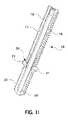
- FIG. 11illustrates a cross-section of the implant of FIG. 10 in a pedicle elongating position
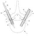
- FIG. 12illustrates the cross-section of the vertebra of FIG. 1 , with the implant inserted into the passage of each pedicle, the implant inserted in the left pedicle shown in the pre-elongating position and the implant inserted in the right pedicle shown in the pedicle elongating position;
- FIG. 13illustrates an enlarged view of the left pedicle of FIG. 12 , showing the implant inserted in the passage in the pre-elongating position and aligned in the passage to begin pedicle elongation;
- FIG. 14illustrates an enlarged view of the right pedicle of FIG. 12 , showing the implant inserted in the passage in a pedicle elongating position, with expandable flanges of the implant filling and securing a widened circumferential cut in the pedicle after pedicle elongation.
- FIG. 1a cross section of a vertebra 1 having a vertebral body 5 , spinal canal 3 and pedicles 2 . Also shown is a guide wire 4 inserted into a central portion of the left pedicle 2 to enter the vertebral body 5 .
- FIG. 2illustrates the cross section of the vertebra 1 of FIG. 1 , showing a cannulated drill 6 passing over the guide wire 4 , drilling a passage in the central portion of the left pedicle 2 but leaving intact outer wall 23 of the left pedicle 2 .
- FIG. 3illustrates the cross section of the vertebra 1 of FIG. 1 following completion of the drilling procedure of FIG. 2 , showing a passage 7 , or hollow tunnel, spanning the central portion of the left pedicle 2 , leaving intact an outer bony wall 23 of the left pedicle 2 .
- FIG. 4illustrates the cross section of the vertebra 1 of FIG. 1 with a side-cutting instrument 8 within the passage 7 of the left pedicle 2 .
- the side-cutting instrument 8has an opening 9 which allows a cutting surface 10 to pass radially outward from a longitudinal center of the side-cutting instrument 8 .
- the cutting surface 10is seen penetrating the outer bony wall 23 of the left pedicle 2 .
- FIG. 5illustrates an enlarged view of the cross section of the vertebra 1 of FIG. 1 , showing the side-cutting instrument 8 within the passage 7 of the left pedicle 2 .
- the cutting surface 10is passing radially outward from the side-cutting instrument 8 and penetrating the outer wall 23 of the left pedicle 2 .
- the cutting surface 10 of the side-cutting instrument 8is capable of extended and withdrawing in such a way that it can penetrate through the bony wall 23 of the left pedicle 2 .
- the side-cutting instrument 8can create a circumferential cut (an osteotomy) through the left pedicle 2 , separating the left pedicle into two portions, an upper portion and a lower portion.
- FIG. 6illustrates a cross-section of the vertebra 1 of FIG. 1 with the cutting surface 10 of the side-cutting instrument 8 extended and penetrating an inner wall 24 (along the spinal canal 3 ) of the left pedicle 2 , creating a cut through to the spinal canal 3 .
- FIG. 7illustrates an enlarged view of the cross section of the vertebra 1 of FIG. 1 , showing the side-cutting instrument 8 within the passage 7 of the left pedicle 2 .
- the cutting surface 10is passing radially outward from the side-cutting instrument 8 , penetrating the inner bony wall 24 of the left pedicle 2 through to the spinal canal 3 .
- FIG. 8illustrates a cross section of the vertebra 1 of FIG. 1 with a completed circumferential cut (an osteotomy) 11 through the left pedicle 2 , separating the left pedicle 2 into an upper portion 12 and a lower portion 13 .
- FIG. 9illustrates a cross section of the vertebra 1 of FIG. 1 , with passages 7 drilled in both the left and right pedicles 2 and circumferential cuts 11 in the midportions of both pedicles 2 .
- the circumferential cuts 11divide the pedicles 2 into upper portions 12 and lower portions 13 in such a way that upper portion 14 and lower portion 15 of the vertebra 1 are completely detached.
- FIG. 10illustrates a cross section of an implant 16 used to elongate the pedicles 2 , thereby widening the circumferential cut 11 and expanding the spinal canal 3 .
- the implant 16also secures the pedicles 2 in an elongated position.
- the implant 16is shown in a pre-elongating position.
- the implant 16includes an outer sleeve 17 and an inner bolt 18 .
- the outer sleeve 17is both externally and internally threaded.
- the inner bolt 18is externally threaded to engage the internal threads of the outer sleeve 17 .
- the outer sleeve 17is divided into an upper portion 19 and a lower portion 20 .
- the upper portion 19 and lower portion 20 of the outer sleeve 17are divided at a separation point 25 .
- the lower portion 20contains expandable flanges 21 which fit into the upper portion 19 of the outer sleeve 17 (as shown in FIG. 10 ) when the implant 16 is in a pre-elongating position.
- the inner bolt 18includes a central barrel 22 , allowing pass-through of a guide wire 4 (shown in FIG. 10 ) to assist in correctly aligning the implant 16 within the passage 7 in the pedicle 2 .
- the inner bolt 18 of the implant 16is partially housed within the outer sleeve 17 .
- a distal end 26 of the inner bolt 18contacts the expandable flanges 21 of the lower portion 20 of the outer sleeve 17 .
- the distal end 26 of the inner bolt 18is designed to not only contact the expandable flanges, but also to wedge itself under a reveal 27 formed due to the flared designed of an upper tip of the expandable flanges 21 .
- FIG. 11illustrates the implant 16 of FIG. 10 in a pedicle elongating position.
- the inner bolt 18is fully inserted into the outer sleeve 17 .
- the lower portion 20 of the outer sleeve 17moves away from the upper portion 19 of the outer sleeve 17 , at separation point 25 , causing overall elongation of the outer sleeve 17 .
- the expandable flanges 21 of the lower portion 20 of the outer sleeve 17are opened (expanded) to extend beyond the outer diameter of the outer sleeve 17 .
- the expandable flanges 21lie within the separation between the upper 19 and lower 20 portions of the outer sleeve 17 .
- the upper 19 and lower 20 portions of the outer sleeve 17are secured in the elongated position by the inner bolt 18 , which is threaded across the junction (separation) between the upper 19 and lower 20 portions of the outer sleeve 17 , securing the upper 19 and lower 20 portions in the pedicle elongating position.
- FIG. 12illustrates a cross section of the vertebra 1 of FIG. 1 , showing the implant 16 inserted into the right and left pedicles 2 .
- the right pedicle 2includes an implant 16 in a pedicle elongating position, while the left pedicle 2 includes an implant in a pre-elongating position.
- FIG. 12shows the right pedicle 2 elongated and the left pedicle in a pre-elongating state.
- the right, elongated pedicle 2causes an asymmetrical tilt to the upper portion 14 of the vertebra 1 in the FIG. 12 view, which is balanced upon elongation of the right pedicle 2 .
- the alignment of the separation point 25in relation to the circumferential cut 11 , of the pre-elongated implant 16 in the left pedicle 2 .
- FIG. 13illustrates an enlarged view of the vertebra 1 of FIG. 1 , showing the implant 16 of FIG. 12 inserted into the left pedicle 2 in a pre-elongating position.
- the implant 16is inserted over the guide wire 4 to ensure correct alignment of the implant 16 within the passage 7 .
- the expandable flanges 21are housed within the upper portion 19 of the outer sleeve 17 .
- the distal end 26 of the inner bolt 18contacts the upper tip of the expandable flanges 21 .
- the separation point 25is positioned adjacent to an upper edge 28 of the circumferential cut (osteotomy) 11 .
- FIG. 14illustrates an enlarged view of the vertebra 1 of FIG. 1 , showing the implant 16 of FIG. 12 inserted into the right pedicle 2 in a pedicle elongating position.
- the inner bolt 18has been threadably inserted completely into the outer sleeve 17 , causing the upper portion 19 and the lower portion 20 of the outer sleeve 17 to separate, further causing the expandable flanges 21 to open, extending beyond the confines of the outer sleeve 17 and into the circumferential cut 11 of the pedicle 2 .
- the expandable flanges 21projecting into the circumferential cut 11 , prevents the upper portion 12 and the lower portion 13 of the pedicle 2 from moving (shortening) back to their original, non-elongated position.
- one method for expanding the spinal canalis summarized as follows: first, the guide wire 4 is placed into the central portion of the pedicle 2 of the vertebra 1 ( FIG. 1 ). Assistance with the entire procedure (operation) could be obtained through fluoroscopy, x-ray, CAT scan or computerized image guided technology, which are all well known in the art of spinal surgery.
- the guide wire 4is over drilled with a cannulated drill 6 , leaving a passage (hollow tunnel) 7 through the central portion of the pedicle 2 but leaving the outer walls 23 intact ( FIG. 2 ).
- the cannulated drill 6is then withdrawn, leaving the guide wire 4 in place ( FIG. 3 ).
- a circumferential cut (osteotomy) 11is placed in the pedicle 2 ( FIGS. 4–7 ), using a side-cutting instrument 8 inserted into the passage 7 in the pedicle 2 .
- the side-cutting instrument 8includes a cutting surface 10 , which is extended and withdrawn from a side opening 9 in the side-cutting instrument 8 .
- the entire pedicle 2is divided in a circumferential fashion, creating the circumferential cut (osteotomy) 11 ( FIG. 8 ).
- both pedicles 2 cutWith both pedicles 2 cut, the upper portion 14 and the lower portion 15 of the vertebra 1 are separated, with no bony material left holding the upper 14 and lower 15 portions together ( FIG. 9 ).
- the pedicles 2are elongated at the site of the circumferential cut 11 using the implant 16 ( FIGS. 10–14 ).
- the implant 16in a pre-elongating state, is first threadably inserted into the pedicle 2 using the guide wire 4 to assist the implant 16 into the correct position (left pedicle 2 of FIG. 12 ).
- the guide wire 4is removed.
- the pre-elongated implant 16is positioned in the passage 7 of the pedicle 2 to align the upper edge 28 of the circumferential cut 11 with the demarcation (separation) point 25 ) between the upper 19 and the lower 20 portions of the outer sleeve 17 ( FIG. 13 ). This precise alignment is not critical, however, as placement of the separation point 25 of the outer sleeve 17 within boundaries of the circumferential cut 11 is sufficient.
- the inner bolt 18 of the implant 16is then threaded into the outer sleeve 17 causing the upper 19 and the lower 20 portions of the outer sleeve 17 to move apart. Because the exterior threads of the upper 19 and the lower 20 portions of the outer sleeve 17 have a good mechanical purchase of the bone of the upper 12 and the lower 13 portions of the pedicle 2 , the pedicle is elongated a few millimeters (by a widening of the circumferential cut 11 ) as the upper 19 and the lower 20 portions of the outer sleeve 17 are drawn apart. The upper portion 19 of the outer sleeve 17 may need to be held motionless to assure that the upper 19 and the lower 20 portions of the outer sleeve 17 begin moving apart.
- the distal end 26 of the inner bolt 18pushes against the upper tip of the expandable flanges 21 , causing the upper 19 and the lower portions 20 of the outer sleeve 17 to separate until the expandable flanges 21 clear the lower edge of the upper portion 19 of the outer sleeve 17 .
- the distal end 26 of the inner bolt 18wedges itself under the reveal 27 ( FIGS. 10–11 ) formed by the upper tip of the expandable flanges 21 , pushing the expandable flanges 21 radially outward due to the force exerted by the inner bolt 18 .
- the radial expansion of the expandable flanges 21allows the inner bolt 18 to travel behind the radially extended expandable flanges 21 and threadably engage the internal threads of the lower portion 20 of the outer sleeve 17 ( FIG. 14 ).
- the inner boltis now threadably attached to the upper 19 and the lower 20 portions of the outer sleeve 17 , thereby mechanically holding the expandable flanges 21 in an open, radially extended position in the circumferential cut 11 , locking the upper 19 and the lower 20 portions of the outer sleeve 17 together, and securing the pedicle 2 in an elongated position (with widened circumferential cut 11 ) to provide an expanded spinal canal ( FIG. 14 ).
- the expandable flanges 21could be made of, or include, an osteogenic material to promote bone healing across the site of the pedicle 2 elongation.
Landscapes
- Health & Medical Sciences (AREA)
- Surgery (AREA)
- Orthopedic Medicine & Surgery (AREA)
- Life Sciences & Earth Sciences (AREA)
- Molecular Biology (AREA)
- Animal Behavior & Ethology (AREA)
- Engineering & Computer Science (AREA)
- Biomedical Technology (AREA)
- Heart & Thoracic Surgery (AREA)
- Medical Informatics (AREA)
- Veterinary Medicine (AREA)
- Nuclear Medicine, Radiotherapy & Molecular Imaging (AREA)
- General Health & Medical Sciences (AREA)
- Public Health (AREA)
- Neurology (AREA)
- Dentistry (AREA)
- Oral & Maxillofacial Surgery (AREA)
- Prostheses (AREA)
- Surgical Instruments (AREA)
- Medicinal Preparation (AREA)
Abstract
Description
- (1) Normal spine structures are not removed and thus normal muscle attachments are maintained.
- (2) There is less chance of spinal instability.
- (3) There is less manipulation of the spinal nerves.
- (4) There is less scaring around the spinal nerves.
- (5) Spinal decompression is more complete.
- (6) The operation is quicker and safer with less blood loss.
- (7) The expanded spinal canal is permanent, preventing recurrent spinal stenosis.
- (8) The procedure can be accomplished in a percutaneous fashion through very small incisions.
Claims (16)
Priority Applications (15)
| Application Number | Priority Date | Filing Date | Title |
|---|---|---|---|
| US10/102,525US7166107B2 (en) | 2000-09-11 | 2002-03-19 | Percutaneous technique and implant for expanding the spinal canal |
| AT03716726TATE446057T1 (en) | 2002-03-19 | 2003-03-19 | IMPLANT FOR EXPANSION IN THE VERTERAL CANAL |
| PCT/US2003/008565WO2003079914A1 (en) | 2002-03-19 | 2003-03-19 | Percutaneous technique and implant for expanding the spinal canal |
| EP03716726AEP1487362B1 (en) | 2002-03-19 | 2003-03-19 | Implant for expanding the spinal canal |
| ES03716726TES2335486T3 (en) | 2002-03-19 | 2003-03-19 | IMPLANT TO EXPAND THE SPINAL CHANNEL. |
| CA2479743ACA2479743C (en) | 2002-03-19 | 2003-03-19 | Percutaneous technique and implant for expanding the spinal canal |
| KR10-2004-7014708AKR20040105777A (en) | 2002-03-19 | 2003-03-19 | Percutaneous technique and implant for expanding the spinal canal |
| JP2003577750AJP4426314B2 (en) | 2002-03-19 | 2003-03-19 | Percutaneous techniques and implants to expand the spinal canal |
| AU2003220421AAU2003220421B8 (en) | 2002-03-19 | 2003-03-19 | Percutaneous technique and implant for expanding the spinal canal |
| DE60329745TDE60329745D1 (en) | 2002-03-19 | 2003-03-19 | IMPLANT FOR EXPANSION IN THE SWIVEL CHANNEL |
| US11/656,790US20070219555A1 (en) | 2000-09-11 | 2007-01-22 | Percutaneous technique and implant for expanding the spinal canal |
| US12/624,946US20100168751A1 (en) | 2002-03-19 | 2009-11-24 | Method, Implant & Instruments for Percutaneous Expansion of the Spinal Canal |
| US12/755,569US8157847B2 (en) | 2000-09-11 | 2010-04-07 | Percutaneous technique and implant for expanding the spinal canal |
| US13/074,169US9044279B2 (en) | 2002-03-19 | 2011-03-29 | Device and method for expanding the spinal canal with spinal column stabilization and spinal deformity correction |
| US13/448,597US8814867B2 (en) | 2000-09-11 | 2012-04-17 | Percutaneous technique and implant for expanding the spinal canal |
Applications Claiming Priority (2)
| Application Number | Priority Date | Filing Date | Title |
|---|---|---|---|
| US09/659,180US6358254B1 (en) | 2000-09-11 | 2000-09-11 | Method and implant for expanding a spinal canal |
| US10/102,525US7166107B2 (en) | 2000-09-11 | 2002-03-19 | Percutaneous technique and implant for expanding the spinal canal |
Related Parent Applications (1)
| Application Number | Title | Priority Date | Filing Date |
|---|---|---|---|
| US09/659,180Continuation-In-PartUS6358254B1 (en) | 2000-09-11 | 2000-09-11 | Method and implant for expanding a spinal canal |
Related Child Applications (1)
| Application Number | Title | Priority Date | Filing Date |
|---|---|---|---|
| US11/656,790ContinuationUS20070219555A1 (en) | 2000-09-11 | 2007-01-22 | Percutaneous technique and implant for expanding the spinal canal |
Publications (2)
| Publication Number | Publication Date |
|---|---|
| US20030004517A1 US20030004517A1 (en) | 2003-01-02 |
| US7166107B2true US7166107B2 (en) | 2007-01-23 |
Family
ID=28452352
Family Applications (1)
| Application Number | Title | Priority Date | Filing Date |
|---|---|---|---|
| US10/102,525Expired - LifetimeUS7166107B2 (en) | 2000-09-11 | 2002-03-19 | Percutaneous technique and implant for expanding the spinal canal |
Country Status (10)
| Country | Link |
|---|---|
| US (1) | US7166107B2 (en) |
| EP (1) | EP1487362B1 (en) |
| JP (1) | JP4426314B2 (en) |
| KR (1) | KR20040105777A (en) |
| AT (1) | ATE446057T1 (en) |
| AU (1) | AU2003220421B8 (en) |
| CA (1) | CA2479743C (en) |
| DE (1) | DE60329745D1 (en) |
| ES (1) | ES2335486T3 (en) |
| WO (1) | WO2003079914A1 (en) |
Cited By (117)
| Publication number | Priority date | Publication date | Assignee | Title |
|---|---|---|---|---|
| US20060089609A1 (en)* | 2004-10-15 | 2006-04-27 | Baxano, Inc. | Devices and methods for tissue modification |
| US20060089633A1 (en)* | 2004-10-15 | 2006-04-27 | Baxano, Inc. | Devices and methods for tissue access |
| US20060122458A1 (en)* | 2004-10-15 | 2006-06-08 | Baxano, Inc. | Devices and methods for tissue access |
| US20060258951A1 (en)* | 2005-05-16 | 2006-11-16 | Baxano, Inc. | Spinal Access and Neural Localization |
| US20070014649A1 (en)* | 2003-04-23 | 2007-01-18 | James Dugal S S | Fixation device and method of fixation |
| US20070106123A1 (en)* | 2005-09-26 | 2007-05-10 | Josef Gorek | Minimally invasive retractor and methods of use |
| US20070213735A1 (en)* | 2004-10-15 | 2007-09-13 | Vahid Saadat | Powered tissue modification devices and methods |
| US20070225703A1 (en)* | 2005-10-15 | 2007-09-27 | Baxano, Inc. | Flexible Tissue Removal Devices and Methods |
| US20070260252A1 (en)* | 2006-05-04 | 2007-11-08 | Baxano, Inc. | Tissue Removal with at Least Partially Flexible Devices |
| US20070260125A1 (en)* | 2006-05-02 | 2007-11-08 | Strauss Kevin R | Minimally open retraction device |
| US20080033465A1 (en)* | 2006-08-01 | 2008-02-07 | Baxano, Inc. | Multi-Wire Tissue Cutter |
| US20080086034A1 (en)* | 2006-08-29 | 2008-04-10 | Baxano, Inc. | Tissue Access Guidewire System and Method |
| US20080091227A1 (en)* | 2006-08-25 | 2008-04-17 | Baxano, Inc. | Surgical probe and method of making |
| US20080147084A1 (en)* | 2006-12-07 | 2008-06-19 | Baxano, Inc. | Tissue removal devices and methods |
| US20080161809A1 (en)* | 2006-10-03 | 2008-07-03 | Baxano, Inc. | Articulating Tissue Cutting Device |
| US20080177268A1 (en)* | 2002-02-14 | 2008-07-24 | Wolfgang Daum | Minimally-Invasive Approach to Bone-Obstructed Soft Tissue |
| US20080262318A1 (en)* | 2007-04-17 | 2008-10-23 | K2M, Inc. | Minimally open interbody access retraction device and surgical method |
| US20080275458A1 (en)* | 2004-10-15 | 2008-11-06 | Bleich Jeffery L | Guidewire exchange systems to treat spinal stenosis |
| US20080312660A1 (en)* | 2007-06-15 | 2008-12-18 | Baxano, Inc. | Devices and methods for measuring the space around a nerve root |
| US20080319488A1 (en)* | 2007-01-10 | 2008-12-25 | Facet Solutions, Inc. | System and method for facet joint replacement |
| US20090018507A1 (en)* | 2007-07-09 | 2009-01-15 | Baxano, Inc. | Spinal access system and method |
| US20090024169A1 (en)* | 2004-06-02 | 2009-01-22 | Facet Solutions, Inc. | System and method for multiple level facet joint arthroplasty and fusion |
| US20090024167A1 (en)* | 2004-02-17 | 2009-01-22 | Facet Solutions, Inc. | Spinal facet implants with mating articulating bearing surface and methods of use |
| US20090024135A1 (en)* | 2004-06-02 | 2009-01-22 | Facet Solutions, Inc. | Surgical measurement systems and methods |
| US20090125036A1 (en)* | 2004-10-15 | 2009-05-14 | Bleich Jeffery L | Devices and methods for selective surgical removal of tissue |
| US20090149865A1 (en)* | 2007-12-07 | 2009-06-11 | Schmitz Gregory P | Tissue modification devices |
| US20090177241A1 (en)* | 2005-10-15 | 2009-07-09 | Bleich Jeffery L | Multiple pathways for spinal nerve root decompression from a single access point |
| US20090177207A1 (en)* | 2005-08-16 | 2009-07-09 | Laurent Schaller | Method of interdigitating flowable material with bone tissue |
| US20090222045A1 (en)* | 2008-02-28 | 2009-09-03 | K2M, Inc. | Minimally Invasive Retractor and Methods of Use |
| US20090222046A1 (en)* | 2008-02-28 | 2009-09-03 | K2M, Inc. | Minimally Invasive Retraction Device Having Removable Blades |
| US20090221877A1 (en)* | 2008-02-28 | 2009-09-03 | K2M, Inc. | Minimally Invasive Retraction Device Having Detachable Blades |
| US20090222044A1 (en)* | 2008-02-28 | 2009-09-03 | K2M, Inc. | Minimally Invasive Retractor Screw and Methods of Use |
| US20090221879A1 (en)* | 2008-02-28 | 2009-09-03 | K2M, Inc. | Minimally Invasive Retractor Having Separable Blades |
| US20090221878A1 (en)* | 2008-02-28 | 2009-09-03 | K2M, Inc. | Minimally Invasive Retractor with Separable Blades and Methods of Use |
| US20100114100A1 (en)* | 2006-12-15 | 2010-05-06 | The Adelman Research Ltd | Technique and device for laminar osteotomy and laminoplasty |
| WO2010068478A1 (en)* | 2008-11-25 | 2010-06-17 | Anderson D Greg | Method, implant & instruments for percutaneous expansion of the spinal canal |
| US20100241165A1 (en)* | 2009-03-18 | 2010-09-23 | Depuy Spine, Inc. | Laminoplasty methods using hinge device |
| US20100241230A1 (en)* | 2009-03-18 | 2010-09-23 | Depuy Spine, Inc. | Laminoplasty methods and devices |
| US20100321426A1 (en)* | 2007-11-22 | 2010-12-23 | Kazuki Suzuki | Image forming apparatus |
| US20100331883A1 (en)* | 2004-10-15 | 2010-12-30 | Schmitz Gregory P | Access and tissue modification systems and methods |
| US20100331900A1 (en)* | 2009-06-25 | 2010-12-30 | Baxano, Inc. | Surgical tools for treatment of spinal stenosis |
| US7887538B2 (en) | 2005-10-15 | 2011-02-15 | Baxano, Inc. | Methods and apparatus for tissue modification |
| US20110040329A1 (en)* | 2009-08-14 | 2011-02-17 | Ainsworth Stephen D | Spinal therapy device with fixated distraction distance |
| US20110112539A1 (en)* | 2008-07-14 | 2011-05-12 | Wallace Michael P | Tissue modification devices |
| US7959577B2 (en) | 2007-09-06 | 2011-06-14 | Baxano, Inc. | Method, system, and apparatus for neural localization |
| US20110144766A1 (en)* | 2008-06-19 | 2011-06-16 | Shreedhar Kale | Allograft Bone Plugs, Systems and Techniques |
| US20110160731A1 (en)* | 2004-10-15 | 2011-06-30 | Bleich Jeffery L | Devices and methods for tissue access |
| CN101695453B (en)* | 2009-10-26 | 2011-07-13 | 杨惠林 | Vertebral arch pedicle extension device |
| US20110224710A1 (en)* | 2004-10-15 | 2011-09-15 | Bleich Jeffery L | Methods, systems and devices for carpal tunnel release |
| US20110230915A1 (en)* | 2002-03-19 | 2011-09-22 | Anderson D Greg | Device and Method for Expanding the Spinal Canal With Spinal Column Stabilization and Spinal Deformity Correction |
| US8048080B2 (en) | 2004-10-15 | 2011-11-01 | Baxano, Inc. | Flexible tissue rasp |
| US20110270317A1 (en)* | 2010-02-05 | 2011-11-03 | Anderson D Greg | Spinal Fixation Device And Technique For Expansion Of The Spinal Canal |
| US8157847B2 (en) | 2000-09-11 | 2012-04-17 | David Greg Anderson | Percutaneous technique and implant for expanding the spinal canal |
| US8221397B2 (en) | 2004-10-15 | 2012-07-17 | Baxano, Inc. | Devices and methods for tissue modification |
| RU2462203C1 (en)* | 2011-05-13 | 2012-09-27 | Федеральное государственное учреждение "Нижегородский научно-исследовательский институт травматологии и ортопедии" Министерства здравоохранения и социального развития Российской Федерации | Method of surgical treatment of spinal stenosis of lumbar spine and device for its realisation |
| US20120245704A1 (en)* | 2011-03-21 | 2012-09-27 | Ronald Childs | Sleeve for bone fixation device |
| US8313528B1 (en) | 2008-03-27 | 2012-11-20 | Spinelogik, Inc. | Intervertebral fusion device and method of use |
| US8333804B1 (en) | 2008-03-27 | 2012-12-18 | Spinelogik, Inc. | Intervertebral fusion device and method of use |
| US8366773B2 (en) | 2005-08-16 | 2013-02-05 | Benvenue Medical, Inc. | Apparatus and method for treating bone |
| US8366712B2 (en) | 2005-10-15 | 2013-02-05 | Baxano, Inc. | Multiple pathways for spinal nerve root decompression from a single access point |
| US8388660B1 (en) | 2006-08-01 | 2013-03-05 | Samy Abdou | Devices and methods for superior fixation of orthopedic devices onto the vertebral column |
| US8398641B2 (en) | 2008-07-01 | 2013-03-19 | Baxano, Inc. | Tissue modification devices and methods |
| US8409206B2 (en) | 2008-07-01 | 2013-04-02 | Baxano, Inc. | Tissue modification devices and methods |
| WO2013059637A1 (en) | 2011-10-21 | 2013-04-25 | Innovative Surgical Designs, Inc. | Surgical implants for percutaneous lengthening of spinal pedicles to correct spinal stenosis |
| US8430881B2 (en) | 2004-10-15 | 2013-04-30 | Baxano, Inc. | Mechanical tissue modification devices and methods |
| US8454617B2 (en) | 2005-08-16 | 2013-06-04 | Benvenue Medical, Inc. | Devices for treating the spine |
| US8535327B2 (en) | 2009-03-17 | 2013-09-17 | Benvenue Medical, Inc. | Delivery apparatus for use with implantable medical devices |
| US8591583B2 (en) | 2005-08-16 | 2013-11-26 | Benvenue Medical, Inc. | Devices for treating the spine |
| WO2014085150A1 (en)* | 2012-11-29 | 2014-06-05 | Warsaw Orthopedic, Inc. | Spinal implant system and method |
| US8801626B2 (en) | 2004-10-15 | 2014-08-12 | Baxano Surgical, Inc. | Flexible neural localization devices and methods |
| US8814873B2 (en) | 2011-06-24 | 2014-08-26 | Benvenue Medical, Inc. | Devices and methods for treating bone tissue |
| US8956284B2 (en) | 2011-01-20 | 2015-02-17 | K2M, Inc. | Minimally invasive retractor and posted screw |
| US9101386B2 (en) | 2004-10-15 | 2015-08-11 | Amendia, Inc. | Devices and methods for treating tissue |
| US9226756B2 (en) | 2012-05-14 | 2016-01-05 | DePuy Synthes Products, Inc. | Bone access instrument |
| US9314253B2 (en) | 2008-07-01 | 2016-04-19 | Amendia, Inc. | Tissue modification devices and methods |
| US9427324B1 (en) | 2010-02-22 | 2016-08-30 | Spinelogik, Inc. | Intervertebral fusion device and method of use |
| US9456829B2 (en) | 2004-10-15 | 2016-10-04 | Amendia, Inc. | Powered tissue modification devices and methods |
| US9788963B2 (en) | 2003-02-14 | 2017-10-17 | DePuy Synthes Products, Inc. | In-situ formed intervertebral fusion device and method |
| US10080583B2 (en) | 2014-12-12 | 2018-09-25 | Depuy Mitel, Llc | Dilator for accessing a joint space |
| US10085783B2 (en) | 2013-03-14 | 2018-10-02 | Izi Medical Products, Llc | Devices and methods for treating bone tissue |
| US10149674B2 (en) | 2015-08-12 | 2018-12-11 | K2M, Inc. | Orthopedic surgical system including surgical access systems, distraction systems, and methods of using same |
| US10499894B2 (en) | 2015-08-12 | 2019-12-10 | K2M, Inc. | Orthopedic surgical system including surgical access systems, distraction systems, and methods of using same |
| US10543107B2 (en) | 2009-12-07 | 2020-01-28 | Samy Abdou | Devices and methods for minimally invasive spinal stabilization and instrumentation |
| US10548740B1 (en) | 2016-10-25 | 2020-02-04 | Samy Abdou | Devices and methods for vertebral bone realignment |
| US10575961B1 (en) | 2011-09-23 | 2020-03-03 | Samy Abdou | Spinal fixation devices and methods of use |
| US10695105B2 (en) | 2012-08-28 | 2020-06-30 | Samy Abdou | Spinal fixation devices and methods of use |
| US10857003B1 (en) | 2015-10-14 | 2020-12-08 | Samy Abdou | Devices and methods for vertebral stabilization |
| US10888433B2 (en) | 2016-12-14 | 2021-01-12 | DePuy Synthes Products, Inc. | Intervertebral implant inserter and related methods |
| US10918498B2 (en) | 2004-11-24 | 2021-02-16 | Samy Abdou | Devices and methods for inter-vertebral orthopedic device placement |
| US10940016B2 (en) | 2017-07-05 | 2021-03-09 | Medos International Sarl | Expandable intervertebral fusion cage |
| US10966840B2 (en) | 2010-06-24 | 2021-04-06 | DePuy Synthes Products, Inc. | Enhanced cage insertion assembly |
| US10973648B1 (en) | 2016-10-25 | 2021-04-13 | Samy Abdou | Devices and methods for vertebral bone realignment |
| US10973652B2 (en) | 2007-06-26 | 2021-04-13 | DePuy Synthes Products, Inc. | Highly lordosed fusion cage |
| US11006982B2 (en) | 2012-02-22 | 2021-05-18 | Samy Abdou | Spinous process fixation devices and methods of use |
| US11173040B2 (en) | 2012-10-22 | 2021-11-16 | Cogent Spine, LLC | Devices and methods for spinal stabilization and instrumentation |
| US11179248B2 (en) | 2018-10-02 | 2021-11-23 | Samy Abdou | Devices and methods for spinal implantation |
| US11273050B2 (en) | 2006-12-07 | 2022-03-15 | DePuy Synthes Products, Inc. | Intervertebral implant |
| US11344424B2 (en) | 2017-06-14 | 2022-05-31 | Medos International Sarl | Expandable intervertebral implant and related methods |
| US11426290B2 (en) | 2015-03-06 | 2022-08-30 | DePuy Synthes Products, Inc. | Expandable intervertebral implant, system, kit and method |
| US11426286B2 (en) | 2020-03-06 | 2022-08-30 | Eit Emerging Implant Technologies Gmbh | Expandable intervertebral implant |
| US11446156B2 (en) | 2018-10-25 | 2022-09-20 | Medos International Sarl | Expandable intervertebral implant, inserter instrument, and related methods |
| US11446155B2 (en) | 2017-05-08 | 2022-09-20 | Medos International Sarl | Expandable cage |
| US11452607B2 (en) | 2010-10-11 | 2022-09-27 | DePuy Synthes Products, Inc. | Expandable interspinous process spacer implant |
| US11497619B2 (en) | 2013-03-07 | 2022-11-15 | DePuy Synthes Products, Inc. | Intervertebral implant |
| US11510788B2 (en) | 2016-06-28 | 2022-11-29 | Eit Emerging Implant Technologies Gmbh | Expandable, angularly adjustable intervertebral cages |
| US11596523B2 (en) | 2016-06-28 | 2023-03-07 | Eit Emerging Implant Technologies Gmbh | Expandable and angularly adjustable articulating intervertebral cages |
| US11602438B2 (en) | 2008-04-05 | 2023-03-14 | DePuy Synthes Products, Inc. | Expandable intervertebral implant |
| US11607321B2 (en) | 2009-12-10 | 2023-03-21 | DePuy Synthes Products, Inc. | Bellows-like expandable interbody fusion cage |
| US11612491B2 (en) | 2009-03-30 | 2023-03-28 | DePuy Synthes Products, Inc. | Zero profile spinal fusion cage |
| US11654033B2 (en) | 2010-06-29 | 2023-05-23 | DePuy Synthes Products, Inc. | Distractible intervertebral implant |
| US11737881B2 (en) | 2008-01-17 | 2023-08-29 | DePuy Synthes Products, Inc. | Expandable intervertebral implant and associated method of manufacturing the same |
| US11752009B2 (en) | 2021-04-06 | 2023-09-12 | Medos International Sarl | Expandable intervertebral fusion cage |
| US11850160B2 (en) | 2021-03-26 | 2023-12-26 | Medos International Sarl | Expandable lordotic intervertebral fusion cage |
| US11911287B2 (en) | 2010-06-24 | 2024-02-27 | DePuy Synthes Products, Inc. | Lateral spondylolisthesis reduction cage |
| USRE49973E1 (en) | 2013-02-28 | 2024-05-21 | DePuy Synthes Products, Inc. | Expandable intervertebral implant, system, kit and method |
| US12090064B2 (en) | 2022-03-01 | 2024-09-17 | Medos International Sarl | Stabilization members for expandable intervertebral implants, and related systems and methods |
| US12440346B2 (en) | 2023-03-31 | 2025-10-14 | DePuy Synthes Products, Inc. | Expandable intervertebral implant |
Families Citing this family (28)
| Publication number | Priority date | Publication date | Assignee | Title |
|---|---|---|---|---|
| US20030212400A1 (en)* | 2002-03-12 | 2003-11-13 | Aesculap Ag & Co. Kg | Methods for treating spinal stenosis by pedicle distraction |
| US6972005B2 (en)* | 2002-05-10 | 2005-12-06 | Boehm Jr Frank H | Dual chamber syringe and dual lumen needle |
| US7708766B2 (en)* | 2003-08-11 | 2010-05-04 | Depuy Spine, Inc. | Distraction screw |
| US7955355B2 (en) | 2003-09-24 | 2011-06-07 | Stryker Spine | Methods and devices for improving percutaneous access in minimally invasive surgeries |
| US8002798B2 (en) | 2003-09-24 | 2011-08-23 | Stryker Spine | System and method for spinal implant placement |
| WO2007079242A2 (en)* | 2005-12-29 | 2007-07-12 | Highgate Orthopedics, Inc. | Devices and methods for bony fixation and disk repair and replaceme |
| US8628534B2 (en)* | 2005-02-02 | 2014-01-14 | DePuy Synthes Products, LLC | Ultrasonic cutting device |
| EP1951159B1 (en) | 2005-11-23 | 2015-08-19 | Trinity Orthopedics | Percutaneous transpedicular access, fusion, discectomy, and stabilization system |
| EP1981422B1 (en) | 2006-02-06 | 2018-10-24 | Stryker European Holdings I, LLC | Rod contouring apparatus for percutaneous pedicle screw extension |
| US20090312764A1 (en)* | 2008-06-11 | 2009-12-17 | Marino James F | Intraosseous transpedicular methods and devices |
| US8439925B2 (en)* | 2009-05-11 | 2013-05-14 | Trinity Orthopedics, Llc | Transiliac-transsacral method of performing lumbar spinal interventions |
| WO2012083101A1 (en) | 2010-12-17 | 2012-06-21 | Synthes Usa, Llc | Methods and systems for minimally invasive posterior arch expansion |
| US9161794B2 (en)* | 2011-04-14 | 2015-10-20 | Globus Medical, Inc. | Expanding spinal anchor |
| CA2833543A1 (en)* | 2011-05-05 | 2012-11-08 | Zyga Technology, Inc. | Sacroiliac fusion system |
| CN102846349B (en)* | 2012-09-29 | 2015-09-30 | 苏州博习医疗科技有限公司 | A kind of vertebral canal expansion Wicresoft cutting tool |
| CN102846353B (en)* | 2012-09-29 | 2015-01-07 | 苏州博习医疗科技有限公司 | Minimally invasive spinal canal dilatation cutting tool |
| CA2846149C (en) | 2013-03-14 | 2018-03-20 | Stryker Spine | Systems and methods for percutaneous spinal fusion |
| US9827020B2 (en) | 2013-03-14 | 2017-11-28 | Stryker European Holdings I, Llc | Percutaneous spinal cross link system and method |
| US9408716B1 (en) | 2013-12-06 | 2016-08-09 | Stryker European Holdings I, Llc | Percutaneous posterior spinal fusion implant construction and method |
| US9744050B1 (en) | 2013-12-06 | 2017-08-29 | Stryker European Holdings I, Llc | Compression and distraction system for percutaneous posterior spinal fusion |
| US10159579B1 (en) | 2013-12-06 | 2018-12-25 | Stryker European Holdings I, Llc | Tubular instruments for percutaneous posterior spinal fusion systems and methods |
| US9861375B2 (en) | 2014-01-09 | 2018-01-09 | Zyga Technology, Inc. | Undercutting system for use in conjunction with sacroiliac fusion |
| CN104138283B (en)* | 2014-08-12 | 2016-03-30 | 南方医科大学 | A kind of pedicle minimally invasive detachment device |
| CA3008161C (en) | 2014-12-09 | 2023-09-26 | John A. Heflin | Spine alignment system |
| CN107041773B (en)* | 2017-04-18 | 2019-08-16 | 中国人民解放军第二军医大学第二附属医院 | Pedicle of vertebral arch cropper |
| CN110090048A (en)* | 2019-05-30 | 2019-08-06 | 朱文婷 | A kind of ultrasonic osteotome bit |
| CN112401967B (en)* | 2020-11-17 | 2024-05-28 | 中国人民解放军空军军医大学 | Sliding type pedicle osteotome |
| CN113288436B (en)* | 2021-06-02 | 2022-10-14 | 上海卓昕医疗科技有限公司 | Bone tissue surgery system |
Citations (42)
| Publication number | Priority date | Publication date | Assignee | Title |
|---|---|---|---|---|
| US3174387A (en)* | 1962-06-04 | 1965-03-23 | Fischer Artur | Expansion bolt |
| US3896504A (en)* | 1972-10-14 | 1975-07-29 | Artur Fischer | Hip joint prosthesis |
| US4013071A (en)* | 1974-11-11 | 1977-03-22 | Lior Rosenberg | Fasteners particularly useful as orthopedic screws |
| US4716893A (en)* | 1985-03-11 | 1988-01-05 | Artur Fischer | Bone fastener |
| US4917704A (en) | 1987-07-09 | 1990-04-17 | Sulzer Brothers Limited | Intervertebral prosthesis |
| US4955908A (en) | 1987-07-09 | 1990-09-11 | Sulzer Brothers Limited | Metallic intervertebral prosthesis |
| US5034011A (en)* | 1990-08-09 | 1991-07-23 | Advanced Spine Fixation Systems Incorporated | Segmental instrumentation of the posterior spine |
| US5059193A (en) | 1989-11-20 | 1991-10-22 | Spine-Tech, Inc. | Expandable spinal implant and surgical method |
| US5108404A (en)* | 1989-02-09 | 1992-04-28 | Arie Scholten | Surgical protocol for fixation of bone using inflatable device |
| US5176678A (en) | 1991-03-14 | 1993-01-05 | Tsou Paul M | Orthopaedic device with angularly adjustable anchor attachments to the vertebrae |
| US5258031A (en) | 1992-01-06 | 1993-11-02 | Danek Medical | Intervertebral disk arthroplasty |
| US5263803A (en)* | 1992-05-13 | 1993-11-23 | Emhart Inc. | Anchor bolt |
| US5425772A (en) | 1993-09-20 | 1995-06-20 | Brantigan; John W. | Prosthetic implant for intervertebral spinal fusion |
| US5480440A (en)* | 1991-08-15 | 1996-01-02 | Smith & Nephew Richards, Inc. | Open surgical technique for vertebral fixation with subcutaneous fixators positioned between the skin and the lumbar fascia of a patient |
| US5489210A (en)* | 1994-05-13 | 1996-02-06 | Hanosh; Frederick N. | Expanding dental implant and method for its use |
| US5496322A (en) | 1992-03-17 | 1996-03-05 | Danek Medical Inc. | Method for subcutaneous suprafascial pedicular internal fixation |
| US5653762A (en) | 1994-03-18 | 1997-08-05 | Pisharodi; Madhavan | Method of stabilizing adjacent vertebrae with rotating, lockable, middle-expanded intervertebral disk stabilizer |
| US5653763A (en) | 1996-03-29 | 1997-08-05 | Fastenetix, L.L.C. | Intervertebral space shape conforming cage device |
| US5722977A (en) | 1996-01-24 | 1998-03-03 | Danek Medical, Inc. | Method and means for anterior lumbar exact cut with quadrilateral osteotome and precision guide/spacer |
| US5725527A (en) | 1992-09-10 | 1998-03-10 | Biedermann Motech Gmbh | Anchoring member |
| US5766251A (en) | 1992-03-13 | 1998-06-16 | Tomihisa Koshino | Wedge-shaped spacer for correction of deformed extremities |
| US5772663A (en) | 1994-02-17 | 1998-06-30 | Whiteside; Leo A. | Surgical device for banding bone with cable |
| US5827285A (en)* | 1996-12-12 | 1998-10-27 | Bramlet; Dale G. | Multipiece interfragmentary fixation assembly |
| US5836948A (en) | 1997-01-02 | 1998-11-17 | Saint Francis Medical Technologies, Llc | Spine distraction implant and method |
| US5964761A (en)* | 1997-07-15 | 1999-10-12 | Kambin; Parviz | Method and instruments for percutaneous arthroscopic disc removal, bone biopsy and fixation of vertebrae |
| US5980572A (en)* | 1997-04-15 | 1999-11-09 | Asahi Kogaku Kogyo Kabushiki Kaisha | Artificial spines |
| US6008433A (en) | 1998-04-23 | 1999-12-28 | Stone; Kevin R. | Osteotomy wedge device, kit and methods for realignment of a varus angulated knee |
| US6018094A (en)* | 1995-02-06 | 2000-01-25 | Biomedical Enterprises, Inc. | Implant and insert assembly for bone and uses thereof |
| US6077268A (en) | 1994-03-29 | 2000-06-20 | Sdgi Holdings, Inc. | Variable angle surgical cable crimp assembly and method |
| US6080157A (en)* | 1995-09-12 | 2000-06-27 | Cg Surgical Limited | Device to stabilize the lamina |
| US6099531A (en) | 1998-08-20 | 2000-08-08 | Bonutti; Peter M. | Changing relationship between bones |
| US6129763A (en)* | 1996-09-13 | 2000-10-10 | Chauvin; Jean-Luc | Expandable osteosynthesis cage |
| US6224599B1 (en) | 1999-05-19 | 2001-05-01 | Matthew G. Baynham | Viewable wedge distractor device |
| US6248106B1 (en) | 2000-02-25 | 2001-06-19 | Bret Ferree | Cross-coupled vertebral stabilizers |
| US6270501B1 (en)* | 1999-11-08 | 2001-08-07 | The Regents Of The University Of Michigan | Surgical method and apparatus and cannulated scalpel for use therein |
| US6358254B1 (en)* | 2000-09-11 | 2002-03-19 | D. Greg Anderson | Method and implant for expanding a spinal canal |
| US6402750B1 (en)* | 2000-04-04 | 2002-06-11 | Spinlabs, Llc | Devices and methods for the treatment of spinal disorders |
| US6428256B2 (en)* | 2000-03-15 | 2002-08-06 | Hilti Aktiengesellschaft | Attachment element for an anchor rod |
| US20030028251A1 (en)* | 2001-07-30 | 2003-02-06 | Mathews Hallett H. | Methods and devices for interbody spinal stabilization |
| US6610091B1 (en)* | 1999-10-22 | 2003-08-26 | Archus Orthopedics Inc. | Facet arthroplasty devices and methods |
| US6635087B2 (en)* | 2001-08-29 | 2003-10-21 | Christopher M. Angelucci | Laminoplasty implants and methods of use |
| US20030212400A1 (en) | 2002-03-12 | 2003-11-13 | Aesculap Ag & Co. Kg | Methods for treating spinal stenosis by pedicle distraction |
Family Cites Families (2)
| Publication number | Priority date | Publication date | Assignee | Title |
|---|---|---|---|---|
| AU516581B2 (en) | 1977-02-24 | 1981-06-11 | Interfix Ltd. | Bone screw |
| JP4206453B2 (en)* | 1999-09-13 | 2009-01-14 | 建治 大畑 | Lingual spacer |
- 2002
- 2002-03-19USUS10/102,525patent/US7166107B2/ennot_activeExpired - Lifetime
- 2003
- 2003-03-19ATAT03716726Tpatent/ATE446057T1/enactive
- 2003-03-19WOPCT/US2003/008565patent/WO2003079914A1/enactiveSearch and Examination
- 2003-03-19KRKR10-2004-7014708Apatent/KR20040105777A/ennot_activeWithdrawn
- 2003-03-19DEDE60329745Tpatent/DE60329745D1/ennot_activeExpired - Lifetime
- 2003-03-19AUAU2003220421Apatent/AU2003220421B8/ennot_activeCeased
- 2003-03-19CACA2479743Apatent/CA2479743C/ennot_activeExpired - Lifetime
- 2003-03-19ESES03716726Tpatent/ES2335486T3/ennot_activeExpired - Lifetime
- 2003-03-19EPEP03716726Apatent/EP1487362B1/ennot_activeExpired - Lifetime
- 2003-03-19JPJP2003577750Apatent/JP4426314B2/ennot_activeExpired - Fee Related
Patent Citations (42)
| Publication number | Priority date | Publication date | Assignee | Title |
|---|---|---|---|---|
| US3174387A (en)* | 1962-06-04 | 1965-03-23 | Fischer Artur | Expansion bolt |
| US3896504A (en)* | 1972-10-14 | 1975-07-29 | Artur Fischer | Hip joint prosthesis |
| US4013071A (en)* | 1974-11-11 | 1977-03-22 | Lior Rosenberg | Fasteners particularly useful as orthopedic screws |
| US4716893A (en)* | 1985-03-11 | 1988-01-05 | Artur Fischer | Bone fastener |
| US4917704A (en) | 1987-07-09 | 1990-04-17 | Sulzer Brothers Limited | Intervertebral prosthesis |
| US4955908A (en) | 1987-07-09 | 1990-09-11 | Sulzer Brothers Limited | Metallic intervertebral prosthesis |
| US5108404A (en)* | 1989-02-09 | 1992-04-28 | Arie Scholten | Surgical protocol for fixation of bone using inflatable device |
| US5059193A (en) | 1989-11-20 | 1991-10-22 | Spine-Tech, Inc. | Expandable spinal implant and surgical method |
| US5034011A (en)* | 1990-08-09 | 1991-07-23 | Advanced Spine Fixation Systems Incorporated | Segmental instrumentation of the posterior spine |
| US5176678A (en) | 1991-03-14 | 1993-01-05 | Tsou Paul M | Orthopaedic device with angularly adjustable anchor attachments to the vertebrae |
| US5480440A (en)* | 1991-08-15 | 1996-01-02 | Smith & Nephew Richards, Inc. | Open surgical technique for vertebral fixation with subcutaneous fixators positioned between the skin and the lumbar fascia of a patient |
| US5258031A (en) | 1992-01-06 | 1993-11-02 | Danek Medical | Intervertebral disk arthroplasty |
| US5766251A (en) | 1992-03-13 | 1998-06-16 | Tomihisa Koshino | Wedge-shaped spacer for correction of deformed extremities |
| US5496322A (en) | 1992-03-17 | 1996-03-05 | Danek Medical Inc. | Method for subcutaneous suprafascial pedicular internal fixation |
| US5263803A (en)* | 1992-05-13 | 1993-11-23 | Emhart Inc. | Anchor bolt |
| US5725527A (en) | 1992-09-10 | 1998-03-10 | Biedermann Motech Gmbh | Anchoring member |
| US5425772A (en) | 1993-09-20 | 1995-06-20 | Brantigan; John W. | Prosthetic implant for intervertebral spinal fusion |
| US5772663A (en) | 1994-02-17 | 1998-06-30 | Whiteside; Leo A. | Surgical device for banding bone with cable |
| US5653762A (en) | 1994-03-18 | 1997-08-05 | Pisharodi; Madhavan | Method of stabilizing adjacent vertebrae with rotating, lockable, middle-expanded intervertebral disk stabilizer |
| US6077268A (en) | 1994-03-29 | 2000-06-20 | Sdgi Holdings, Inc. | Variable angle surgical cable crimp assembly and method |
| US5489210A (en)* | 1994-05-13 | 1996-02-06 | Hanosh; Frederick N. | Expanding dental implant and method for its use |
| US6018094A (en)* | 1995-02-06 | 2000-01-25 | Biomedical Enterprises, Inc. | Implant and insert assembly for bone and uses thereof |
| US6080157A (en)* | 1995-09-12 | 2000-06-27 | Cg Surgical Limited | Device to stabilize the lamina |
| US5722977A (en) | 1996-01-24 | 1998-03-03 | Danek Medical, Inc. | Method and means for anterior lumbar exact cut with quadrilateral osteotome and precision guide/spacer |
| US5653763A (en) | 1996-03-29 | 1997-08-05 | Fastenetix, L.L.C. | Intervertebral space shape conforming cage device |
| US6129763A (en)* | 1996-09-13 | 2000-10-10 | Chauvin; Jean-Luc | Expandable osteosynthesis cage |
| US5827285A (en)* | 1996-12-12 | 1998-10-27 | Bramlet; Dale G. | Multipiece interfragmentary fixation assembly |
| US5836948A (en) | 1997-01-02 | 1998-11-17 | Saint Francis Medical Technologies, Llc | Spine distraction implant and method |
| US5980572A (en)* | 1997-04-15 | 1999-11-09 | Asahi Kogaku Kogyo Kabushiki Kaisha | Artificial spines |
| US5964761A (en)* | 1997-07-15 | 1999-10-12 | Kambin; Parviz | Method and instruments for percutaneous arthroscopic disc removal, bone biopsy and fixation of vertebrae |
| US6008433A (en) | 1998-04-23 | 1999-12-28 | Stone; Kevin R. | Osteotomy wedge device, kit and methods for realignment of a varus angulated knee |
| US6099531A (en) | 1998-08-20 | 2000-08-08 | Bonutti; Peter M. | Changing relationship between bones |
| US6224599B1 (en) | 1999-05-19 | 2001-05-01 | Matthew G. Baynham | Viewable wedge distractor device |
| US6610091B1 (en)* | 1999-10-22 | 2003-08-26 | Archus Orthopedics Inc. | Facet arthroplasty devices and methods |
| US6270501B1 (en)* | 1999-11-08 | 2001-08-07 | The Regents Of The University Of Michigan | Surgical method and apparatus and cannulated scalpel for use therein |
| US6248106B1 (en) | 2000-02-25 | 2001-06-19 | Bret Ferree | Cross-coupled vertebral stabilizers |
| US6428256B2 (en)* | 2000-03-15 | 2002-08-06 | Hilti Aktiengesellschaft | Attachment element for an anchor rod |
| US6402750B1 (en)* | 2000-04-04 | 2002-06-11 | Spinlabs, Llc | Devices and methods for the treatment of spinal disorders |
| US6358254B1 (en)* | 2000-09-11 | 2002-03-19 | D. Greg Anderson | Method and implant for expanding a spinal canal |
| US20030028251A1 (en)* | 2001-07-30 | 2003-02-06 | Mathews Hallett H. | Methods and devices for interbody spinal stabilization |
| US6635087B2 (en)* | 2001-08-29 | 2003-10-21 | Christopher M. Angelucci | Laminoplasty implants and methods of use |
| US20030212400A1 (en) | 2002-03-12 | 2003-11-13 | Aesculap Ag & Co. Kg | Methods for treating spinal stenosis by pedicle distraction |
Non-Patent Citations (3)
| Title |
|---|
| Patent Abstracts of Japan, vol. 1999, No. 04, Apr. 30, 1999, and JP 11 004840 A (Takasugi Shinsuke; Asahi Optical Co. Ltd.), Jan. 12, 1999. |
| Patent Abstracts of Japan, vol. 2000, No. 08, Oct. 6, 2000, and JP 2000 139970 A (Nomura Hironobu), May 23, 2000. |
| Patent Abstracts of Japan, vol. 2000, No. 09, Oct. 13, 2000, and JP 2000 152951 A (Asahi Optical Co. Ltd.), Jun. 6, 2000. |
Cited By (322)
| Publication number | Priority date | Publication date | Assignee | Title |
|---|---|---|---|---|
| US8157847B2 (en) | 2000-09-11 | 2012-04-17 | David Greg Anderson | Percutaneous technique and implant for expanding the spinal canal |
| US8814867B2 (en) | 2000-09-11 | 2014-08-26 | Innovative Surgical Designs, Inc. | Percutaneous technique and implant for expanding the spinal canal |
| US20080177268A1 (en)* | 2002-02-14 | 2008-07-24 | Wolfgang Daum | Minimally-Invasive Approach to Bone-Obstructed Soft Tissue |
| US9044279B2 (en) | 2002-03-19 | 2015-06-02 | Innovative Surgical Designs, Inc. | Device and method for expanding the spinal canal with spinal column stabilization and spinal deformity correction |
| US20110230915A1 (en)* | 2002-03-19 | 2011-09-22 | Anderson D Greg | Device and Method for Expanding the Spinal Canal With Spinal Column Stabilization and Spinal Deformity Correction |
| US20100168751A1 (en)* | 2002-03-19 | 2010-07-01 | Anderson D Greg | Method, Implant & Instruments for Percutaneous Expansion of the Spinal Canal |
| US10786361B2 (en) | 2003-02-14 | 2020-09-29 | DePuy Synthes Products, Inc. | In-situ formed intervertebral fusion device and method |
| US9814590B2 (en) | 2003-02-14 | 2017-11-14 | DePuy Synthes Products, Inc. | In-situ formed intervertebral fusion device and method |
| US10085843B2 (en) | 2003-02-14 | 2018-10-02 | DePuy Synthes Products, Inc. | In-situ formed intervertebral fusion device and method |
| US10376372B2 (en) | 2003-02-14 | 2019-08-13 | DePuy Synthes Products, Inc. | In-situ formed intervertebral fusion device and method |
| US11207187B2 (en) | 2003-02-14 | 2021-12-28 | DePuy Synthes Products, Inc. | In-situ formed intervertebral fusion device and method |
| US11096794B2 (en) | 2003-02-14 | 2021-08-24 | DePuy Synthes Products, Inc. | In-situ formed intervertebral fusion device and method |
| US10405986B2 (en) | 2003-02-14 | 2019-09-10 | DePuy Synthes Products, Inc. | In-situ formed intervertebral fusion device and method |
| US11432938B2 (en) | 2003-02-14 | 2022-09-06 | DePuy Synthes Products, Inc. | In-situ intervertebral fusion device and method |
| US9925060B2 (en) | 2003-02-14 | 2018-03-27 | DePuy Synthes Products, Inc. | In-situ formed intervertebral fusion device and method |
| US10639164B2 (en) | 2003-02-14 | 2020-05-05 | DePuy Synthes Products, Inc. | In-situ formed intervertebral fusion device and method |
| US9788963B2 (en) | 2003-02-14 | 2017-10-17 | DePuy Synthes Products, Inc. | In-situ formed intervertebral fusion device and method |
| US10420651B2 (en) | 2003-02-14 | 2019-09-24 | DePuy Synthes Products, Inc. | In-situ formed intervertebral fusion device and method |
| US10433971B2 (en) | 2003-02-14 | 2019-10-08 | DePuy Synthes Products, Inc. | In-situ formed intervertebral fusion device and method |
| US10575959B2 (en) | 2003-02-14 | 2020-03-03 | DePuy Synthes Products, Inc. | In-situ formed intervertebral fusion device and method |
| US9801729B2 (en) | 2003-02-14 | 2017-10-31 | DePuy Synthes Products, Inc. | In-situ formed intervertebral fusion device and method |
| US10555817B2 (en) | 2003-02-14 | 2020-02-11 | DePuy Synthes Products, Inc. | In-situ formed intervertebral fusion device and method |
| US9808351B2 (en) | 2003-02-14 | 2017-11-07 | DePuy Synthes Products, Inc. | In-situ formed intervertebral fusion device and method |
| US10583013B2 (en) | 2003-02-14 | 2020-03-10 | DePuy Synthes Products, Inc. | In-situ formed intervertebral fusion device and method |
| US10492918B2 (en) | 2003-02-14 | 2019-12-03 | DePuy Synthes Products, Inc. | In-situ formed intervertebral fusion device and method |
| US9814589B2 (en) | 2003-02-14 | 2017-11-14 | DePuy Synthes Products, Inc. | In-situ formed intervertebral fusion device and method |
| US20070014649A1 (en)* | 2003-04-23 | 2007-01-18 | James Dugal S S | Fixation device and method of fixation |
| US7998177B2 (en) | 2004-02-17 | 2011-08-16 | Gmedelaware 2 Llc | Linked bilateral spinal facet implants and methods of use |
| US20090024167A1 (en)* | 2004-02-17 | 2009-01-22 | Facet Solutions, Inc. | Spinal facet implants with mating articulating bearing surface and methods of use |
| US20090024168A1 (en)* | 2004-02-17 | 2009-01-22 | Facet Solutions, Inc. | Linked bilateral spinal facet implants and methods of use |
| US20090030459A1 (en)* | 2004-02-17 | 2009-01-29 | Facet Solutions, Inc. | Spinal facet implant with spherical implant apposition surface and bone bed and methods of use |
| US8906063B2 (en) | 2004-02-17 | 2014-12-09 | Gmedelaware 2 Llc | Spinal facet joint implant |
| US7914560B2 (en) | 2004-02-17 | 2011-03-29 | Gmedelaware 2 Llc | Spinal facet implant with spherical implant apposition surface and bone bed and methods of use |
| US7998178B2 (en) | 2004-02-17 | 2011-08-16 | Gmedelaware 2 Llc | Linked bilateral spinal facet implants and methods of use |
| US20090024169A1 (en)* | 2004-06-02 | 2009-01-22 | Facet Solutions, Inc. | System and method for multiple level facet joint arthroplasty and fusion |
| US20090024135A1 (en)* | 2004-06-02 | 2009-01-22 | Facet Solutions, Inc. | Surgical measurement systems and methods |
| US20090024134A1 (en)* | 2004-06-02 | 2009-01-22 | Facet Solutions, Inc. | Surgical measurement and resection framework |
| US7815648B2 (en) | 2004-06-02 | 2010-10-19 | Facet Solutions, Inc | Surgical measurement systems and methods |
| US8777994B2 (en) | 2004-06-02 | 2014-07-15 | Gmedelaware 2 Llc | System and method for multiple level facet joint arthroplasty and fusion |
| US20060094976A1 (en)* | 2004-10-15 | 2006-05-04 | Baxano, Inc. | Devices and methods for selective surgical removal of tissue |
| US7938830B2 (en) | 2004-10-15 | 2011-05-10 | Baxano, Inc. | Powered tissue modification devices and methods |
| US9456829B2 (en) | 2004-10-15 | 2016-10-04 | Amendia, Inc. | Powered tissue modification devices and methods |
| US8647346B2 (en) | 2004-10-15 | 2014-02-11 | Baxano Surgical, Inc. | Devices and methods for tissue modification |
| US8617163B2 (en) | 2004-10-15 | 2013-12-31 | Baxano Surgical, Inc. | Methods, systems and devices for carpal tunnel release |
| US8613745B2 (en) | 2004-10-15 | 2013-12-24 | Baxano Surgical, Inc. | Methods, systems and devices for carpal tunnel release |
| US8579902B2 (en) | 2004-10-15 | 2013-11-12 | Baxano Signal, Inc. | Devices and methods for tissue modification |
| US20070213735A1 (en)* | 2004-10-15 | 2007-09-13 | Vahid Saadat | Powered tissue modification devices and methods |
| US9463041B2 (en) | 2004-10-15 | 2016-10-11 | Amendia, Inc. | Devices and methods for tissue access |
| US8652138B2 (en) | 2004-10-15 | 2014-02-18 | Baxano Surgical, Inc. | Flexible tissue rasp |
| US10052116B2 (en) | 2004-10-15 | 2018-08-21 | Amendia, Inc. | Devices and methods for treating tissue |
| US7553307B2 (en) | 2004-10-15 | 2009-06-30 | Baxano, Inc. | Devices and methods for tissue modification |
| US7555343B2 (en) | 2004-10-15 | 2009-06-30 | Baxano, Inc. | Devices and methods for selective surgical removal of tissue |
| US8430881B2 (en) | 2004-10-15 | 2013-04-30 | Baxano, Inc. | Mechanical tissue modification devices and methods |
| US7738968B2 (en) | 2004-10-15 | 2010-06-15 | Baxano, Inc. | Devices and methods for selective surgical removal of tissue |
| US7738969B2 (en) | 2004-10-15 | 2010-06-15 | Baxano, Inc. | Devices and methods for selective surgical removal of tissue |
| US20090125036A1 (en)* | 2004-10-15 | 2009-05-14 | Bleich Jeffery L | Devices and methods for selective surgical removal of tissue |
| US7740631B2 (en) | 2004-10-15 | 2010-06-22 | Baxano, Inc. | Devices and methods for tissue modification |
| US20060095028A1 (en)* | 2004-10-15 | 2006-05-04 | Baxano, Inc. | Devices and methods for tissue access |
| US20110160731A1 (en)* | 2004-10-15 | 2011-06-30 | Bleich Jeffery L | Devices and methods for tissue access |
| US8801626B2 (en) | 2004-10-15 | 2014-08-12 | Baxano Surgical, Inc. | Flexible neural localization devices and methods |
| US8568416B2 (en) | 2004-10-15 | 2013-10-29 | Baxano Surgical, Inc. | Access and tissue modification systems and methods |
| US20080275458A1 (en)* | 2004-10-15 | 2008-11-06 | Bleich Jeffery L | Guidewire exchange systems to treat spinal stenosis |
| US20060100651A1 (en)* | 2004-10-15 | 2006-05-11 | Baxano, Inc. | Devices and methods for tissue access |
| US20060089609A1 (en)* | 2004-10-15 | 2006-04-27 | Baxano, Inc. | Devices and methods for tissue modification |
| US20110224710A1 (en)* | 2004-10-15 | 2011-09-15 | Bleich Jeffery L | Methods, systems and devices for carpal tunnel release |
| US20060122458A1 (en)* | 2004-10-15 | 2006-06-08 | Baxano, Inc. | Devices and methods for tissue access |
| US9101386B2 (en) | 2004-10-15 | 2015-08-11 | Amendia, Inc. | Devices and methods for treating tissue |
| US20100331883A1 (en)* | 2004-10-15 | 2010-12-30 | Schmitz Gregory P | Access and tissue modification systems and methods |
| US8257356B2 (en) | 2004-10-15 | 2012-09-04 | Baxano, Inc. | Guidewire exchange systems to treat spinal stenosis |
| US20060089633A1 (en)* | 2004-10-15 | 2006-04-27 | Baxano, Inc. | Devices and methods for tissue access |
| US9247952B2 (en) | 2004-10-15 | 2016-02-02 | Amendia, Inc. | Devices and methods for tissue access |
| US8221397B2 (en) | 2004-10-15 | 2012-07-17 | Baxano, Inc. | Devices and methods for tissue modification |
| US8192435B2 (en) | 2004-10-15 | 2012-06-05 | Baxano, Inc. | Devices and methods for tissue modification |
| US9320618B2 (en) | 2004-10-15 | 2016-04-26 | Amendia, Inc. | Access and tissue modification systems and methods |
| US7918849B2 (en) | 2004-10-15 | 2011-04-05 | Baxano, Inc. | Devices and methods for tissue access |
| US20110098708A9 (en)* | 2004-10-15 | 2011-04-28 | Vahid Saadat | Powered tissue modification devices and methods |
| US8048080B2 (en) | 2004-10-15 | 2011-11-01 | Baxano, Inc. | Flexible tissue rasp |
| US11382647B2 (en) | 2004-10-15 | 2022-07-12 | Spinal Elements, Inc. | Devices and methods for treating tissue |
| US20060089640A1 (en)* | 2004-10-15 | 2006-04-27 | Baxano, Inc. | Devices and methods for tissue modification |
| US7963915B2 (en) | 2004-10-15 | 2011-06-21 | Baxano, Inc. | Devices and methods for tissue access |
| US9345491B2 (en) | 2004-10-15 | 2016-05-24 | Amendia, Inc. | Flexible tissue rasp |
| US11096799B2 (en) | 2004-11-24 | 2021-08-24 | Samy Abdou | Devices and methods for inter-vertebral orthopedic device placement |
| US10918498B2 (en) | 2004-11-24 | 2021-02-16 | Samy Abdou | Devices and methods for inter-vertebral orthopedic device placement |
| US11992423B2 (en) | 2004-11-24 | 2024-05-28 | Samy Abdou | Devices and methods for inter-vertebral orthopedic device placement |
| US7578819B2 (en) | 2005-05-16 | 2009-08-25 | Baxano, Inc. | Spinal access and neural localization |
| US20100010334A1 (en)* | 2005-05-16 | 2010-01-14 | Bleich Jeffery L | Spinal access and neural localization |
| US8419653B2 (en) | 2005-05-16 | 2013-04-16 | Baxano, Inc. | Spinal access and neural localization |
| US20060258951A1 (en)* | 2005-05-16 | 2006-11-16 | Baxano, Inc. | Spinal Access and Neural Localization |
| US7666227B2 (en) | 2005-08-16 | 2010-02-23 | Benvenue Medical, Inc. | Devices for limiting the movement of material introduced between layers of spinal tissue |
| US8801787B2 (en) | 2005-08-16 | 2014-08-12 | Benvenue Medical, Inc. | Methods of distracting tissue layers of the human spine |
| US7967865B2 (en) | 2005-08-16 | 2011-06-28 | Benvenue Medical, Inc. | Devices for limiting the movement of material introduced between layers of spinal tissue |
| US7963993B2 (en) | 2005-08-16 | 2011-06-21 | Benvenue Medical, Inc. | Methods of distracting tissue layers of the human spine |
| US8591583B2 (en) | 2005-08-16 | 2013-11-26 | Benvenue Medical, Inc. | Devices for treating the spine |
| US8057544B2 (en) | 2005-08-16 | 2011-11-15 | Benvenue Medical, Inc. | Methods of distracting tissue layers of the human spine |
| US8556978B2 (en) | 2005-08-16 | 2013-10-15 | Benvenue Medical, Inc. | Devices and methods for treating the vertebral body |
| US7666226B2 (en) | 2005-08-16 | 2010-02-23 | Benvenue Medical, Inc. | Spinal tissue distraction devices |
| US20090177207A1 (en)* | 2005-08-16 | 2009-07-09 | Laurent Schaller | Method of interdigitating flowable material with bone tissue |
| US9326866B2 (en) | 2005-08-16 | 2016-05-03 | Benvenue Medical, Inc. | Devices for treating the spine |
| US7670374B2 (en) | 2005-08-16 | 2010-03-02 | Benvenue Medical, Inc. | Methods of distracting tissue layers of the human spine |
| US7670375B2 (en) | 2005-08-16 | 2010-03-02 | Benvenue Medical, Inc. | Methods for limiting the movement of material introduced between layers of spinal tissue |
| US7955391B2 (en) | 2005-08-16 | 2011-06-07 | Benvenue Medical, Inc. | Methods for limiting the movement of material introduced between layers of spinal tissue |
| US9259326B2 (en) | 2005-08-16 | 2016-02-16 | Benvenue Medical, Inc. | Spinal tissue distraction devices |
| US8454617B2 (en) | 2005-08-16 | 2013-06-04 | Benvenue Medical, Inc. | Devices for treating the spine |
| US10028840B2 (en) | 2005-08-16 | 2018-07-24 | Izi Medical Products, Llc | Spinal tissue distraction devices |
| US7967864B2 (en) | 2005-08-16 | 2011-06-28 | Benvenue Medical, Inc. | Spinal tissue distraction devices |
| US20100174375A1 (en)* | 2005-08-16 | 2010-07-08 | Laurent Schaller | Spinal Tissue Distraction Devices |
| US8808376B2 (en) | 2005-08-16 | 2014-08-19 | Benvenue Medical, Inc. | Intravertebral implants |
| US20100174321A1 (en)* | 2005-08-16 | 2010-07-08 | Laurent Schaller | Methods of Distracting Tissue Layers of the Human Spine |
| US9066808B2 (en) | 2005-08-16 | 2015-06-30 | Benvenue Medical, Inc. | Method of interdigitating flowable material with bone tissue |
| US9044338B2 (en) | 2005-08-16 | 2015-06-02 | Benvenue Medical, Inc. | Spinal tissue distraction devices |
| US7785368B2 (en) | 2005-08-16 | 2010-08-31 | Benvenue Medical, Inc. | Spinal tissue distraction devices |
| US8882836B2 (en) | 2005-08-16 | 2014-11-11 | Benvenue Medical, Inc. | Apparatus and method for treating bone |
| US8979929B2 (en) | 2005-08-16 | 2015-03-17 | Benvenue Medical, Inc. | Spinal tissue distraction devices |
| US9788974B2 (en) | 2005-08-16 | 2017-10-17 | Benvenue Medical, Inc. | Spinal tissue distraction devices |
| US8961609B2 (en) | 2005-08-16 | 2015-02-24 | Benvenue Medical, Inc. | Devices for distracting tissue layers of the human spine |
| US8366773B2 (en) | 2005-08-16 | 2013-02-05 | Benvenue Medical, Inc. | Apparatus and method for treating bone |
| US9161779B2 (en) | 2005-09-26 | 2015-10-20 | K2M, Inc. | Minimally invasive retractor and methods of use |
| US8734338B2 (en) | 2005-09-26 | 2014-05-27 | K2M, Inc. | Minimally invasive retractor and methods of use |
| US20070106123A1 (en)* | 2005-09-26 | 2007-05-10 | Josef Gorek | Minimally invasive retractor and methods of use |
| US8298138B2 (en) | 2005-09-26 | 2012-10-30 | K2M, Inc. | Minimally invasive retractor and methods of use |
| US9510858B2 (en) | 2005-09-26 | 2016-12-06 | K2M, Inc. | Minimally invasive retractor and methods of use |
| US20110054259A1 (en)* | 2005-09-26 | 2011-03-03 | K2M, Inc. | Minimally invasive retractor and methods of use |
| US7846093B2 (en) | 2005-09-26 | 2010-12-07 | K2M, Inc. | Minimally invasive retractor and methods of use |
| US8092456B2 (en) | 2005-10-15 | 2012-01-10 | Baxano, Inc. | Multiple pathways for spinal nerve root decompression from a single access point |
| US9125682B2 (en) | 2005-10-15 | 2015-09-08 | Amendia, Inc. | Multiple pathways for spinal nerve root decompression from a single access point |
| US20070225703A1 (en)* | 2005-10-15 | 2007-09-27 | Baxano, Inc. | Flexible Tissue Removal Devices and Methods |
| US7887538B2 (en) | 2005-10-15 | 2011-02-15 | Baxano, Inc. | Methods and apparatus for tissue modification |
| US20090177241A1 (en)* | 2005-10-15 | 2009-07-09 | Bleich Jeffery L | Multiple pathways for spinal nerve root decompression from a single access point |
| US8366712B2 (en) | 2005-10-15 | 2013-02-05 | Baxano, Inc. | Multiple pathways for spinal nerve root decompression from a single access point |
| US8062298B2 (en) | 2005-10-15 | 2011-11-22 | Baxano, Inc. | Flexible tissue removal devices and methods |
| US9492151B2 (en) | 2005-10-15 | 2016-11-15 | Amendia, Inc. | Multiple pathways for spinal nerve root decompression from a single access point |
| US10485529B2 (en) | 2006-05-02 | 2019-11-26 | K2M, Inc. | Minimally open retraction device |
| US8696560B2 (en) | 2006-05-02 | 2014-04-15 | K2M, Inc. | Minimally open retraction device |
| US20070260125A1 (en)* | 2006-05-02 | 2007-11-08 | Strauss Kevin R | Minimally open retraction device |
| US9131934B2 (en) | 2006-05-02 | 2015-09-15 | K2M, Inc. | Minimally open retraction device |
| US9681863B2 (en) | 2006-05-02 | 2017-06-20 | K2M, Inc. | Minimally open retraction device |
| US11529132B2 (en) | 2006-05-02 | 2022-12-20 | K2M, Inc. | Minimally open retraction device |
| US8585704B2 (en) | 2006-05-04 | 2013-11-19 | Baxano Surgical, Inc. | Flexible tissue removal devices and methods |
| US8062300B2 (en) | 2006-05-04 | 2011-11-22 | Baxano, Inc. | Tissue removal with at least partially flexible devices |
| US9351741B2 (en) | 2006-05-04 | 2016-05-31 | Amendia, Inc. | Flexible tissue removal devices and methods |
| US20070260252A1 (en)* | 2006-05-04 | 2007-11-08 | Baxano, Inc. | Tissue Removal with at Least Partially Flexible Devices |
| US8388660B1 (en) | 2006-08-01 | 2013-03-05 | Samy Abdou | Devices and methods for superior fixation of orthopedic devices onto the vertebral column |
| US20080033465A1 (en)* | 2006-08-01 | 2008-02-07 | Baxano, Inc. | Multi-Wire Tissue Cutter |
| US20080091227A1 (en)* | 2006-08-25 | 2008-04-17 | Baxano, Inc. | Surgical probe and method of making |
| US7857813B2 (en) | 2006-08-29 | 2010-12-28 | Baxano, Inc. | Tissue access guidewire system and method |
| US8551097B2 (en) | 2006-08-29 | 2013-10-08 | Baxano Surgical, Inc. | Tissue access guidewire system and method |
| US20110046613A1 (en)* | 2006-08-29 | 2011-02-24 | Gregory Schmitz | Tissue access guidewire system and method |
| US8845637B2 (en) | 2006-08-29 | 2014-09-30 | Baxano Surgical, Inc. | Tissue access guidewire system and method |
| US20080086034A1 (en)* | 2006-08-29 | 2008-04-10 | Baxano, Inc. | Tissue Access Guidewire System and Method |
| US20080161809A1 (en)* | 2006-10-03 | 2008-07-03 | Baxano, Inc. | Articulating Tissue Cutting Device |
| US11432942B2 (en) | 2006-12-07 | 2022-09-06 | DePuy Synthes Products, Inc. | Intervertebral implant |
| US11273050B2 (en) | 2006-12-07 | 2022-03-15 | DePuy Synthes Products, Inc. | Intervertebral implant |
| US11660206B2 (en) | 2006-12-07 | 2023-05-30 | DePuy Synthes Products, Inc. | Intervertebral implant |
| US11497618B2 (en) | 2006-12-07 | 2022-11-15 | DePuy Synthes Products, Inc. | Intervertebral implant |
| US11712345B2 (en) | 2006-12-07 | 2023-08-01 | DePuy Synthes Products, Inc. | Intervertebral implant |
| US20080147084A1 (en)* | 2006-12-07 | 2008-06-19 | Baxano, Inc. | Tissue removal devices and methods |
| US11642229B2 (en) | 2006-12-07 | 2023-05-09 | DePuy Synthes Products, Inc. | Intervertebral implant |
| US20100114100A1 (en)* | 2006-12-15 | 2010-05-06 | The Adelman Research Ltd | Technique and device for laminar osteotomy and laminoplasty |
| US8529570B2 (en) | 2006-12-15 | 2013-09-10 | The Adelman Research Ltd | Technique and device for laminar osteotomy and laminoplasty |
| US8252027B2 (en) | 2007-01-10 | 2012-08-28 | Gmedelaware 2 Llc | System and method for facet joint replacement |
| US20090012566A1 (en)* | 2007-01-10 | 2009-01-08 | Facet Solutions, Inc. | System and method for facet joint replacement |
| US8206418B2 (en) | 2007-01-10 | 2012-06-26 | Gmedelaware 2 Llc | System and method for facet joint replacement with detachable coupler |
| US20080319488A1 (en)* | 2007-01-10 | 2008-12-25 | Facet Solutions, Inc. | System and method for facet joint replacement |
| US8211147B2 (en) | 2007-01-10 | 2012-07-03 | Gmedelaware 2 Llc | System and method for facet joint replacement |
| US8968408B2 (en) | 2007-02-21 | 2015-03-03 | Benvenue Medical, Inc. | Devices for treating the spine |
| US10575963B2 (en) | 2007-02-21 | 2020-03-03 | Benvenue Medical, Inc. | Devices for treating the spine |
| US10426629B2 (en) | 2007-02-21 | 2019-10-01 | Benvenue Medical, Inc. | Devices for treating the spine |
| US10285821B2 (en) | 2007-02-21 | 2019-05-14 | Benvenue Medical, Inc. | Devices for treating the spine |
| US9642712B2 (en) | 2007-02-21 | 2017-05-09 | Benvenue Medical, Inc. | Methods for treating the spine |
| US8702759B2 (en) | 2007-04-17 | 2014-04-22 | Gmedelaware 2 Llc | System and method for bone anchorage |
| US10405841B2 (en) | 2007-04-17 | 2019-09-10 | K2M, Inc. | Minimally open interbody access retraction device and surgical method |
| US20080319485A1 (en)* | 2007-04-17 | 2008-12-25 | Facet Solutions, Inc. | System and method for implant anchorage with anti-rotation features |
| US11083447B2 (en) | 2007-04-17 | 2021-08-10 | K2M, Inc. | Minimally open interbody access retraction device and surgical method |
| US9050144B2 (en) | 2007-04-17 | 2015-06-09 | Gmedelaware 2 Llc | System and method for implant anchorage with anti-rotation features |
| US20080262318A1 (en)* | 2007-04-17 | 2008-10-23 | K2M, Inc. | Minimally open interbody access retraction device and surgical method |
| US11812940B2 (en) | 2007-04-17 | 2023-11-14 | K2M, Inc. | Minimally open interbody access retraction device and surgical method |
| US20080319489A1 (en)* | 2007-04-17 | 2008-12-25 | Facet Solutions, Inc. | System and method for bone anchorage |
| US8979749B2 (en) | 2007-04-17 | 2015-03-17 | K2M, Inc. | Minimally open interbody access retraction device and surgical method |
| US9675337B2 (en) | 2007-04-17 | 2017-06-13 | K2M, Inc. | Minimally open interbody access retraction device and surgical method |
| US20080312660A1 (en)* | 2007-06-15 | 2008-12-18 | Baxano, Inc. | Devices and methods for measuring the space around a nerve root |
| US10973652B2 (en) | 2007-06-26 | 2021-04-13 | DePuy Synthes Products, Inc. | Highly lordosed fusion cage |
| US11622868B2 (en) | 2007-06-26 | 2023-04-11 | DePuy Synthes Products, Inc. | Highly lordosed fusion cage |
| US20090018507A1 (en)* | 2007-07-09 | 2009-01-15 | Baxano, Inc. | Spinal access system and method |
| US8303516B2 (en) | 2007-09-06 | 2012-11-06 | Baxano, Inc. | Method, system and apparatus for neural localization |
| US7959577B2 (en) | 2007-09-06 | 2011-06-14 | Baxano, Inc. | Method, system, and apparatus for neural localization |
| US20100321426A1 (en)* | 2007-11-22 | 2010-12-23 | Kazuki Suzuki | Image forming apparatus |
| US8192436B2 (en) | 2007-12-07 | 2012-06-05 | Baxano, Inc. | Tissue modification devices |
| US8663228B2 (en) | 2007-12-07 | 2014-03-04 | Baxano Surgical, Inc. | Tissue modification devices |
| US20090149865A1 (en)* | 2007-12-07 | 2009-06-11 | Schmitz Gregory P | Tissue modification devices |
| US9463029B2 (en) | 2007-12-07 | 2016-10-11 | Amendia, Inc. | Tissue modification devices |
| US11737881B2 (en) | 2008-01-17 | 2023-08-29 | DePuy Synthes Products, Inc. | Expandable intervertebral implant and associated method of manufacturing the same |
| US8870878B2 (en) | 2008-02-28 | 2014-10-28 | K2M, Inc. | Minimally invasive retractor and methods of use |
| US8376940B2 (en) | 2008-02-28 | 2013-02-19 | K2M, Inc. | Minimally invasive retractor with separable blades and methods of use |
| US8097026B2 (en) | 2008-02-28 | 2012-01-17 | K2M, Inc. | Minimally invasive retraction device having removable blades |
| US8747407B2 (en) | 2008-02-28 | 2014-06-10 | K2M, Inc. | Minimally invasive retractor and methods of use |
| US20090222045A1 (en)* | 2008-02-28 | 2009-09-03 | K2M, Inc. | Minimally Invasive Retractor and Methods of Use |
| US20090222046A1 (en)* | 2008-02-28 | 2009-09-03 | K2M, Inc. | Minimally Invasive Retraction Device Having Removable Blades |
| US20090221878A1 (en)* | 2008-02-28 | 2009-09-03 | K2M, Inc. | Minimally Invasive Retractor with Separable Blades and Methods of Use |
| US20090221877A1 (en)* | 2008-02-28 | 2009-09-03 | K2M, Inc. | Minimally Invasive Retraction Device Having Detachable Blades |
| US20090221879A1 (en)* | 2008-02-28 | 2009-09-03 | K2M, Inc. | Minimally Invasive Retractor Having Separable Blades |
| US8414625B2 (en) | 2008-02-28 | 2013-04-09 | K2M, Inc. | Minimally invasive retraction device having removable blades |
| US20090222044A1 (en)* | 2008-02-28 | 2009-09-03 | K2M, Inc. | Minimally Invasive Retractor Screw and Methods of Use |
| US8246538B2 (en) | 2008-02-28 | 2012-08-21 | K2M, Inc. | Minimally invasive retractor with separable blades and methods of use |
| US8932210B2 (en) | 2008-02-28 | 2015-01-13 | K2M, Inc. | Minimally invasive retraction device having detachable blades |
| US9028549B1 (en) | 2008-03-27 | 2015-05-12 | Spinelogik, Inc. | Intervertebral fusion device and method of use |
| US8313528B1 (en) | 2008-03-27 | 2012-11-20 | Spinelogik, Inc. | Intervertebral fusion device and method of use |
| US8523945B1 (en) | 2008-03-27 | 2013-09-03 | Spinelogik, Inc. | Method and apparatus for affixing a fusion member to vertebral bodies |
| US9730805B1 (en) | 2008-03-27 | 2017-08-15 | Spinelogik, Inc. | Intervertebral fusion device and method or use |
| US9717600B1 (en) | 2008-03-27 | 2017-08-01 | Spinelogik, Inc. | Bioabsorbable anchoring member for insertion into a vertebral body |
| US8551175B1 (en) | 2008-03-27 | 2013-10-08 | Spinelogik, Inc. | Method and apparatus for retaining a fusion member while delivering the fusion member between two vertebral bodies |
| US8460385B1 (en) | 2008-03-27 | 2013-06-11 | Spinelogik, Inc. | Fusion member for insertion between vertebral bodies |
| US8382839B1 (en) | 2008-03-27 | 2013-02-26 | Spinelogik, Inc. | Intervertebral fusion device and method of use |
| US8333804B1 (en) | 2008-03-27 | 2012-12-18 | Spinelogik, Inc. | Intervertebral fusion device and method of use |
| US11617655B2 (en) | 2008-04-05 | 2023-04-04 | DePuy Synthes Products, Inc. | Expandable intervertebral implant |
| US11701234B2 (en) | 2008-04-05 | 2023-07-18 | DePuy Synthes Products, Inc. | Expandable intervertebral implant |
| US11602438B2 (en) | 2008-04-05 | 2023-03-14 | DePuy Synthes Products, Inc. | Expandable intervertebral implant |
| US11707359B2 (en) | 2008-04-05 | 2023-07-25 | DePuy Synthes Products, Inc. | Expandable intervertebral implant |
| US11712342B2 (en) | 2008-04-05 | 2023-08-01 | DePuy Synthes Products, Inc. | Expandable intervertebral implant |
| US11712341B2 (en) | 2008-04-05 | 2023-08-01 | DePuy Synthes Products, Inc. | Expandable intervertebral implant |
| US12011361B2 (en) | 2008-04-05 | 2024-06-18 | DePuy Synthes Products, Inc. | Expandable intervertebral implant |
| US12023255B2 (en) | 2008-04-05 | 2024-07-02 | DePuy Synthes Products, Inc. | Expandable inter vertebral implant |
| US8840677B2 (en) | 2008-06-19 | 2014-09-23 | DePuy Synthes Products, LLC | Allograft bone plugs, systems and techniques |
| US20110144766A1 (en)* | 2008-06-19 | 2011-06-16 | Shreedhar Kale | Allograft Bone Plugs, Systems and Techniques |
| US8398641B2 (en) | 2008-07-01 | 2013-03-19 | Baxano, Inc. | Tissue modification devices and methods |
| US8409206B2 (en) | 2008-07-01 | 2013-04-02 | Baxano, Inc. | Tissue modification devices and methods |
| US9314253B2 (en) | 2008-07-01 | 2016-04-19 | Amendia, Inc. | Tissue modification devices and methods |
| US20110112539A1 (en)* | 2008-07-14 | 2011-05-12 | Wallace Michael P | Tissue modification devices |
| US8845639B2 (en) | 2008-07-14 | 2014-09-30 | Baxano Surgical, Inc. | Tissue modification devices |
| WO2010068478A1 (en)* | 2008-11-25 | 2010-06-17 | Anderson D Greg | Method, implant & instruments for percutaneous expansion of the spinal canal |
| US8535327B2 (en) | 2009-03-17 | 2013-09-17 | Benvenue Medical, Inc. | Delivery apparatus for use with implantable medical devices |
| US20100241230A1 (en)* | 2009-03-18 | 2010-09-23 | Depuy Spine, Inc. | Laminoplasty methods and devices |
| US20100241165A1 (en)* | 2009-03-18 | 2010-09-23 | Depuy Spine, Inc. | Laminoplasty methods using hinge device |
| US8435265B2 (en) | 2009-03-18 | 2013-05-07 | Depuy Spine, Inc. | Laminoplasty methods using hinge device |
| US9155569B2 (en) | 2009-03-18 | 2015-10-13 | DePuy Synthes Products, Inc. | Laminoplasty methods using hinge device |
| US8147528B2 (en) | 2009-03-18 | 2012-04-03 | Depuy Spine, Inc. | Laminoplasty methods and devices |
| US12097124B2 (en) | 2009-03-30 | 2024-09-24 | DePuy Synthes Products, Inc. | Zero profile spinal fusion cage |
| US11612491B2 (en) | 2009-03-30 | 2023-03-28 | DePuy Synthes Products, Inc. | Zero profile spinal fusion cage |
| US20100331900A1 (en)* | 2009-06-25 | 2010-12-30 | Baxano, Inc. | Surgical tools for treatment of spinal stenosis |
| US8394102B2 (en) | 2009-06-25 | 2013-03-12 | Baxano, Inc. | Surgical tools for treatment of spinal stenosis |
| US8747472B2 (en)* | 2009-08-14 | 2014-06-10 | Baxano Surgical, Inc. | Spinal therapy device with fixated distraction distance |
| US20110040329A1 (en)* | 2009-08-14 | 2011-02-17 | Ainsworth Stephen D | Spinal therapy device with fixated distraction distance |
| CN101695453B (en)* | 2009-10-26 | 2011-07-13 | 杨惠林 | Vertebral arch pedicle extension device |
| US11918486B2 (en) | 2009-12-07 | 2024-03-05 | Samy Abdou | Devices and methods for minimally invasive spinal stabilization and instrumentation |
| US10945861B2 (en) | 2009-12-07 | 2021-03-16 | Samy Abdou | Devices and methods for minimally invasive spinal stabilization and instrumentation |
| US10543107B2 (en) | 2009-12-07 | 2020-01-28 | Samy Abdou | Devices and methods for minimally invasive spinal stabilization and instrumentation |
| US10857004B2 (en) | 2009-12-07 | 2020-12-08 | Samy Abdou | Devices and methods for minimally invasive spinal stabilization and instrumentation |
| US10610380B2 (en) | 2009-12-07 | 2020-04-07 | Samy Abdou | Devices and methods for minimally invasive spinal stabilization and instrumentation |
| US11607321B2 (en) | 2009-12-10 | 2023-03-21 | DePuy Synthes Products, Inc. | Bellows-like expandable interbody fusion cage |
| US20110270317A1 (en)* | 2010-02-05 | 2011-11-03 | Anderson D Greg | Spinal Fixation Device And Technique For Expansion Of The Spinal Canal |
| US8834528B2 (en)* | 2010-02-05 | 2014-09-16 | D. Greg Anderson | Spinal fixation device and technique for expansion of the spinal canal |
| US9427324B1 (en) | 2010-02-22 | 2016-08-30 | Spinelogik, Inc. | Intervertebral fusion device and method of use |
| WO2011126825A3 (en)* | 2010-03-29 | 2012-04-05 | Anderson D Greg | Device and method for expanding the spinal canal with spinal column stabilization and spinal deformity correction |
| US11911287B2 (en) | 2010-06-24 | 2024-02-27 | DePuy Synthes Products, Inc. | Lateral spondylolisthesis reduction cage |
| US11872139B2 (en) | 2010-06-24 | 2024-01-16 | DePuy Synthes Products, Inc. | Enhanced cage insertion assembly |
| US10966840B2 (en) | 2010-06-24 | 2021-04-06 | DePuy Synthes Products, Inc. | Enhanced cage insertion assembly |
| US12318304B2 (en) | 2010-06-24 | 2025-06-03 | DePuy Synthes Products, Inc. | Lateral spondylolisthesis reduction cage |
| US11654033B2 (en) | 2010-06-29 | 2023-05-23 | DePuy Synthes Products, Inc. | Distractible intervertebral implant |
| US11452607B2 (en) | 2010-10-11 | 2022-09-27 | DePuy Synthes Products, Inc. | Expandable interspinous process spacer implant |
| US8956284B2 (en) | 2011-01-20 | 2015-02-17 | K2M, Inc. | Minimally invasive retractor and posted screw |
| US20120245704A1 (en)* | 2011-03-21 | 2012-09-27 | Ronald Childs | Sleeve for bone fixation device |
| US20170303973A1 (en)* | 2011-03-21 | 2017-10-26 | DePuy Synthes Products, Inc. | Sleeve for bone fixation device |
| US9687278B2 (en)* | 2011-03-21 | 2017-06-27 | Ronald Childs | Sleeve for bone fixation device |
| US10729475B2 (en)* | 2011-03-21 | 2020-08-04 | Ronald C. Childs | Sleeve for bone fixation device |
| US11950812B2 (en)* | 2011-03-21 | 2024-04-09 | Ronald C. Childs | Sleeve for bone fixation device |
| US20200323565A1 (en)* | 2011-03-21 | 2020-10-15 | Ronald C. Childs | Sleeve for bone fixation device |
| RU2462203C1 (en)* | 2011-05-13 | 2012-09-27 | Федеральное государственное учреждение "Нижегородский научно-исследовательский институт травматологии и ортопедии" Министерства здравоохранения и социального развития Российской Федерации | Method of surgical treatment of spinal stenosis of lumbar spine and device for its realisation |
| US9314252B2 (en) | 2011-06-24 | 2016-04-19 | Benvenue Medical, Inc. | Devices and methods for treating bone tissue |
| US8814873B2 (en) | 2011-06-24 | 2014-08-26 | Benvenue Medical, Inc. | Devices and methods for treating bone tissue |
| US11517449B2 (en) | 2011-09-23 | 2022-12-06 | Samy Abdou | Spinal fixation devices and methods of use |
| US10575961B1 (en) | 2011-09-23 | 2020-03-03 | Samy Abdou | Spinal fixation devices and methods of use |
| US11324608B2 (en) | 2011-09-23 | 2022-05-10 | Samy Abdou | Spinal fixation devices and methods of use |
| US12167973B2 (en) | 2011-09-23 | 2024-12-17 | Samy Abdou | Spinal fixation devices and methods of use |
| WO2013059637A1 (en) | 2011-10-21 | 2013-04-25 | Innovative Surgical Designs, Inc. | Surgical implants for percutaneous lengthening of spinal pedicles to correct spinal stenosis |
| US11839413B2 (en) | 2012-02-22 | 2023-12-12 | Samy Abdou | Spinous process fixation devices and methods of use |
| US11006982B2 (en) | 2012-02-22 | 2021-05-18 | Samy Abdou | Spinous process fixation devices and methods of use |
| US9788843B2 (en) | 2012-05-14 | 2017-10-17 | DePuy Synthes Products, Inc. | Bone access instrument |
| US9226756B2 (en) | 2012-05-14 | 2016-01-05 | DePuy Synthes Products, Inc. | Bone access instrument |
| US10695105B2 (en) | 2012-08-28 | 2020-06-30 | Samy Abdou | Spinal fixation devices and methods of use |
| US11559336B2 (en) | 2012-08-28 | 2023-01-24 | Samy Abdou | Spinal fixation devices and methods of use |
| US11918483B2 (en) | 2012-10-22 | 2024-03-05 | Cogent Spine Llc | Devices and methods for spinal stabilization and instrumentation |
| US11173040B2 (en) | 2012-10-22 | 2021-11-16 | Cogent Spine, LLC | Devices and methods for spinal stabilization and instrumentation |
| US9918752B2 (en) | 2012-11-29 | 2018-03-20 | Warsaw Orthopedic, Inc. | Spinal implant system and method |
| WO2014085150A1 (en)* | 2012-11-29 | 2014-06-05 | Warsaw Orthopedic, Inc. | Spinal implant system and method |
| USRE49973E1 (en) | 2013-02-28 | 2024-05-21 | DePuy Synthes Products, Inc. | Expandable intervertebral implant, system, kit and method |
| US11850164B2 (en) | 2013-03-07 | 2023-12-26 | DePuy Synthes Products, Inc. | Intervertebral implant |
| US11497619B2 (en) | 2013-03-07 | 2022-11-15 | DePuy Synthes Products, Inc. | Intervertebral implant |
| US10085783B2 (en) | 2013-03-14 | 2018-10-02 | Izi Medical Products, Llc | Devices and methods for treating bone tissue |
| US10080583B2 (en) | 2014-12-12 | 2018-09-25 | Depuy Mitel, Llc | Dilator for accessing a joint space |
| US11266438B2 (en) | 2014-12-12 | 2022-03-08 | DePuy Synthes Products, Inc. | Dilator for accessing a joint space |
| US12089869B2 (en) | 2014-12-12 | 2024-09-17 | DePuy Synthes Products, Inc. | Dilator for accessing a joint space |
| US11426290B2 (en) | 2015-03-06 | 2022-08-30 | DePuy Synthes Products, Inc. | Expandable intervertebral implant, system, kit and method |
| US10149674B2 (en) | 2015-08-12 | 2018-12-11 | K2M, Inc. | Orthopedic surgical system including surgical access systems, distraction systems, and methods of using same |
| US10499894B2 (en) | 2015-08-12 | 2019-12-10 | K2M, Inc. | Orthopedic surgical system including surgical access systems, distraction systems, and methods of using same |
| US12048426B2 (en) | 2015-08-12 | 2024-07-30 | K2M, Inc. | Orthopedic surgical system including surgical access systems, distraction systems, and methods of using same |
| US11006942B2 (en) | 2015-08-12 | 2021-05-18 | K2M, Inc. | Orthopedic surgical system including surgical access systems, distraction systems, and methods of using same |
| US10857003B1 (en) | 2015-10-14 | 2020-12-08 | Samy Abdou | Devices and methods for vertebral stabilization |
| US11246718B2 (en) | 2015-10-14 | 2022-02-15 | Samy Abdou | Devices and methods for vertebral stabilization |
| US11596522B2 (en) | 2016-06-28 | 2023-03-07 | Eit Emerging Implant Technologies Gmbh | Expandable and angularly adjustable intervertebral cages with articulating joint |
| US11510788B2 (en) | 2016-06-28 | 2022-11-29 | Eit Emerging Implant Technologies Gmbh | Expandable, angularly adjustable intervertebral cages |
| US11596523B2 (en) | 2016-06-28 | 2023-03-07 | Eit Emerging Implant Technologies Gmbh | Expandable and angularly adjustable articulating intervertebral cages |
| US12390343B2 (en) | 2016-06-28 | 2025-08-19 | Eit Emerging Implant Technologies Gmbh | Expandable, angularly adjustable intervertebral cages |
| US12433757B2 (en) | 2016-06-28 | 2025-10-07 | Eit Emerging Implant Technologies Gmbh | Expandable, angularly adjustable and articulating intervertebral cages |
| US10744000B1 (en) | 2016-10-25 | 2020-08-18 | Samy Abdou | Devices and methods for vertebral bone realignment |
| US10548740B1 (en) | 2016-10-25 | 2020-02-04 | Samy Abdou | Devices and methods for vertebral bone realignment |
| US10973648B1 (en) | 2016-10-25 | 2021-04-13 | Samy Abdou | Devices and methods for vertebral bone realignment |
| US11752008B1 (en) | 2016-10-25 | 2023-09-12 | Samy Abdou | Devices and methods for vertebral bone realignment |
| US11259935B1 (en) | 2016-10-25 | 2022-03-01 | Samy Abdou | Devices and methods for vertebral bone realignment |
| US11058548B1 (en) | 2016-10-25 | 2021-07-13 | Samy Abdou | Devices and methods for vertebral bone realignment |
| US10888433B2 (en) | 2016-12-14 | 2021-01-12 | DePuy Synthes Products, Inc. | Intervertebral implant inserter and related methods |
| US12427031B2 (en) | 2017-05-08 | 2025-09-30 | Medos International Sarl | Expandable cage |
| US11446155B2 (en) | 2017-05-08 | 2022-09-20 | Medos International Sarl | Expandable cage |
| US11344424B2 (en) | 2017-06-14 | 2022-05-31 | Medos International Sarl | Expandable intervertebral implant and related methods |
| US10940016B2 (en) | 2017-07-05 | 2021-03-09 | Medos International Sarl | Expandable intervertebral fusion cage |
| US11179248B2 (en) | 2018-10-02 | 2021-11-23 | Samy Abdou | Devices and methods for spinal implantation |
| US11446156B2 (en) | 2018-10-25 | 2022-09-20 | Medos International Sarl | Expandable intervertebral implant, inserter instrument, and related methods |
| US11806245B2 (en) | 2020-03-06 | 2023-11-07 | Eit Emerging Implant Technologies Gmbh | Expandable intervertebral implant |
| US11426286B2 (en) | 2020-03-06 | 2022-08-30 | Eit Emerging Implant Technologies Gmbh | Expandable intervertebral implant |
| US11850160B2 (en) | 2021-03-26 | 2023-12-26 | Medos International Sarl | Expandable lordotic intervertebral fusion cage |
| US12023258B2 (en) | 2021-04-06 | 2024-07-02 | Medos International Sarl | Expandable intervertebral fusion cage |
| US11752009B2 (en) | 2021-04-06 | 2023-09-12 | Medos International Sarl | Expandable intervertebral fusion cage |
| US12090064B2 (en) | 2022-03-01 | 2024-09-17 | Medos International Sarl | Stabilization members for expandable intervertebral implants, and related systems and methods |
| US12440346B2 (en) | 2023-03-31 | 2025-10-14 | DePuy Synthes Products, Inc. | Expandable intervertebral implant |
Also Published As
| Publication number | Publication date |
|---|---|
| ATE446057T1 (en) | 2009-11-15 |
| AU2003220421B8 (en) | 2009-05-07 |
| AU2003220421B2 (en) | 2009-01-08 |
| CA2479743A1 (en) | 2003-10-02 |
| AU2003220421A1 (en) | 2003-10-08 |
| DE60329745D1 (en) | 2009-12-03 |
| CA2479743C (en) | 2012-01-03 |
| JP4426314B2 (en) | 2010-03-03 |
| EP1487362A1 (en) | 2004-12-22 |
| WO2003079914B1 (en) | 2003-11-13 |
| EP1487362A4 (en) | 2007-07-04 |
| KR20040105777A (en) | 2004-12-16 |
| ES2335486T3 (en) | 2010-03-29 |
| WO2003079914A1 (en) | 2003-10-02 |
| JP2005520619A (en) | 2005-07-14 |
| EP1487362B1 (en) | 2009-10-21 |
| US20030004517A1 (en) | 2003-01-02 |
Similar Documents
| Publication | Publication Date | Title |
|---|---|---|
| US7166107B2 (en) | Percutaneous technique and implant for expanding the spinal canal | |
| US8157847B2 (en) | Percutaneous technique and implant for expanding the spinal canal | |
| US8956359B2 (en) | Method, implant and instruments for percutaneous expansion of the spinal canal | |
| US9445848B2 (en) | Surgical implants for percutaneous lengthening of spinal pedicles to correct spinal stenosis | |
| EP1257212B9 (en) | Apparatus for providing anterior trans-sacral access to spinal vertebrae | |
| AU666908B2 (en) | Method for subcutaneous suprafascial pedicular internal fixation | |
| EP2529668B1 (en) | Apparatus for access to and/or treatment of the spine | |
| AU2001288516A1 (en) | A method and implant for expanding a spinal canal | |
| HK1198807B (en) | Surgical implants for percutaneous lengthening of spinal pedicles to correct spinal stenosis |
Legal Events
| Date | Code | Title | Description |
|---|---|---|---|
| AS | Assignment | Owner name:DEPUY ACROMED, INC., MASSACHUSETTS Free format text:ASSIGNMENT OF ASSIGNORS INTEREST;ASSIGNOR:ANDERSON, D. GREG, M.D.;REEL/FRAME:013804/0022 Effective date:20030214 | |
| AS | Assignment | Owner name:DEPUY ACROMED, INC., MASSACHUSETTS Free format text:ASSIGNMENT OF ASSIGNORS INTEREST;ASSIGNOR:ANDERSON, D. GREG;REEL/FRAME:014220/0948 Effective date:20030214 | |
| FEPP | Fee payment procedure | Free format text:PAYOR NUMBER ASSIGNED (ORIGINAL EVENT CODE: ASPN); ENTITY STATUS OF PATENT OWNER: SMALL ENTITY | |
| AS | Assignment | Owner name:ANDERSON, MD, DAVID GREG, NEW JERSEY Free format text:ASSIGNMENT OF ASSIGNORS INTEREST;ASSIGNOR:DEPUY SPINE, INC.;REEL/FRAME:017767/0657 Effective date:20060518 | |
| STCF | Information on status: patent grant | Free format text:PATENTED CASE | |
| FPAY | Fee payment | Year of fee payment:4 | |
| AS | Assignment | Owner name:INNOVATIVE SURGICAL DESIGNS, INC., INDIANA Free format text:ASSIGNMENT OF ASSIGNORS INTEREST;ASSIGNOR:ANDERSON, D. GREG;REEL/FRAME:032251/0346 Effective date:20110927 | |
| FPAY | Fee payment | Year of fee payment:8 | |
| MAFP | Maintenance fee payment | Free format text:PAYMENT OF MAINTENANCE FEE, 12TH YR, SMALL ENTITY (ORIGINAL EVENT CODE: M2553) Year of fee payment:12 |