US7164662B2 - Network delay identification method and apparatus - Google Patents
Network delay identification method and apparatusDownload PDFInfo
- Publication number
- US7164662B2 US7164662B2US09/888,085US88808501AUS7164662B2US 7164662 B2US7164662 B2US 7164662B2US 88808501 AUS88808501 AUS 88808501AUS 7164662 B2US7164662 B2US 7164662B2
- Authority
- US
- United States
- Prior art keywords
- ibs
- bits
- tones
- processor
- code
- Prior art date
- Legal status (The legal status is an assumption and is not a legal conclusion. Google has not performed a legal analysis and makes no representation as to the accuracy of the status listed.)
- Expired - Fee Related, expires
Links
- 238000000034methodMethods0.000titleclaimsdescription17
- 230000001360synchronised effectEffects0.000claimsabstractdescription8
- 238000004891communicationMethods0.000claimsdescription25
- 230000001413cellular effectEffects0.000claimsdescription18
- 238000005070samplingMethods0.000claimsdescription8
- 230000008569processEffects0.000claimsdescription5
- 238000010586diagramMethods0.000description31
- 230000011664signalingEffects0.000description15
- 230000005540biological transmissionEffects0.000description12
- 238000011084recoveryMethods0.000description9
- 230000003044adaptive effectEffects0.000description7
- 238000001914filtrationMethods0.000description6
- 230000008901benefitEffects0.000description3
- 230000010354integrationEffects0.000description3
- 238000007493shaping processMethods0.000description3
- 230000010267cellular communicationEffects0.000description2
- 230000002596correlated effectEffects0.000description2
- 230000000875corresponding effectEffects0.000description2
- 230000005236sound signalEffects0.000description2
- 230000007704transitionEffects0.000description2
- IRLPACMLTUPBCL-KQYNXXCUSA-N5'-adenylyl sulfateChemical compoundC1=NC=2C(N)=NC=NC=2N1[C@@H]1O[C@H](COP(O)(=O)OS(O)(=O)=O)[C@@H](O)[C@H]1OIRLPACMLTUPBCL-KQYNXXCUSA-N0.000description1
- 230000002411adverseEffects0.000description1
- 230000003321amplificationEffects0.000description1
- 230000008859changeEffects0.000description1
- 230000001276controlling effectEffects0.000description1
- 230000007423decreaseEffects0.000description1
- 230000000694effectsEffects0.000description1
- 238000005516engineering processMethods0.000description1
- 238000013507mappingMethods0.000description1
- 230000000116mitigating effectEffects0.000description1
- 238000012986modificationMethods0.000description1
- 230000004048modificationEffects0.000description1
- 238000003199nucleic acid amplification methodMethods0.000description1
- 238000013139quantizationMethods0.000description1
- 238000009738saturatingMethods0.000description1
- 238000001228spectrumMethods0.000description1
- 238000012795verificationMethods0.000description1
Images


Classifications
- H—ELECTRICITY
- H04—ELECTRIC COMMUNICATION TECHNIQUE
- H04J—MULTIPLEX COMMUNICATION
- H04J3/00—Time-division multiplex systems
- H04J3/02—Details
- H04J3/06—Synchronising arrangements
- H04J3/0635—Clock or time synchronisation in a network
- H04J3/0682—Clock or time synchronisation in a network by delay compensation, e.g. by compensation of propagation delay or variations thereof, by ranging
- G—PHYSICS
- G01—MEASURING; TESTING
- G01S—RADIO DIRECTION-FINDING; RADIO NAVIGATION; DETERMINING DISTANCE OR VELOCITY BY USE OF RADIO WAVES; LOCATING OR PRESENCE-DETECTING BY USE OF THE REFLECTION OR RERADIATION OF RADIO WAVES; ANALOGOUS ARRANGEMENTS USING OTHER WAVES
- G01S5/00—Position-fixing by co-ordinating two or more direction or position line determinations; Position-fixing by co-ordinating two or more distance determinations
- G01S5/0009—Transmission of position information to remote stations
- G01S5/0018—Transmission from mobile station to base station
- G01S5/0027—Transmission from mobile station to base station of actual mobile position, i.e. position determined on mobile
- G—PHYSICS
- G08—SIGNALLING
- G08G—TRAFFIC CONTROL SYSTEMS
- G08G1/00—Traffic control systems for road vehicles
- G08G1/123—Traffic control systems for road vehicles indicating the position of vehicles, e.g. scheduled vehicles; Managing passenger vehicles circulating according to a fixed timetable, e.g. buses, trains, trams
- G08G1/127—Traffic control systems for road vehicles indicating the position of vehicles, e.g. scheduled vehicles; Managing passenger vehicles circulating according to a fixed timetable, e.g. buses, trains, trams to a central station ; Indicators in a central station
- G—PHYSICS
- G01—MEASURING; TESTING
- G01S—RADIO DIRECTION-FINDING; RADIO NAVIGATION; DETERMINING DISTANCE OR VELOCITY BY USE OF RADIO WAVES; LOCATING OR PRESENCE-DETECTING BY USE OF THE REFLECTION OR RERADIATION OF RADIO WAVES; ANALOGOUS ARRANGEMENTS USING OTHER WAVES
- G01S2205/00—Position-fixing by co-ordinating two or more direction or position line determinations; Position-fixing by co-ordinating two or more distance determinations
- G01S2205/001—Transmission of position information to remote stations
- G01S2205/002—Transmission of position information to remote stations for traffic control, mobile tracking, guidance, surveillance or anti-collision
- G—PHYSICS
- G01—MEASURING; TESTING
- G01S—RADIO DIRECTION-FINDING; RADIO NAVIGATION; DETERMINING DISTANCE OR VELOCITY BY USE OF RADIO WAVES; LOCATING OR PRESENCE-DETECTING BY USE OF THE REFLECTION OR RERADIATION OF RADIO WAVES; ANALOGOUS ARRANGEMENTS USING OTHER WAVES
- G01S2205/00—Position-fixing by co-ordinating two or more direction or position line determinations; Position-fixing by co-ordinating two or more distance determinations
- G01S2205/001—Transmission of position information to remote stations
- G01S2205/008—Transmission of position information to remote stations using a mobile telephone network
- H—ELECTRICITY
- H04—ELECTRIC COMMUNICATION TECHNIQUE
- H04W—WIRELESS COMMUNICATION NETWORKS
- H04W56/00—Synchronisation arrangements
- H04W56/0055—Synchronisation arrangements determining timing error of reception due to propagation delay
- H04W56/0065—Synchronisation arrangements determining timing error of reception due to propagation delay using measurement of signal travel time
- H04W56/007—Open loop measurement
- H04W56/0075—Open loop measurement based on arrival time vs. expected arrival time
- H04W56/0085—Open loop measurement based on arrival time vs. expected arrival time detecting a given structure in the signal
Definitions
- Portable devicesoften need to be synchronized with a reference system.
- GPSGlobal Positioning Systems
- the portable GPS deviceuses a clock to obtain a position fix with a GPS satellite.
- the GPS signalsare not available, for example, because the satellites are out of view, or when the mobile device has not acquired the satellite signal, the mobile device must be resynchronized with a reference clock due to drift in the mobile unit clock over time.
- Network delayis defined as the time required to send synchronization information over a network between a reference station and a remote station. In order to accurately resynchronize a remote clock with a reference clock, it is necessary to account for this network delay.
- This patent applicationdescribes a system for resynchronizing a clock in a portable device by sending a pulse from a reference station to the portable device.
- the portable devicerelays a pulse back to the reference station.
- the reference stationmeasures the time difference between the transmitted pulse and the received pulse. This time difference is then used to resynchronize the clock in the portable device.
- the present inventionprovides another technique for identifying network delay.
- Network delayis determined in order to synchronize a clock in a mobile station with a reference clock.
- Tonesare generated that represent a sequence of bits in a synchronization flag.
- the tonesare sampled beginning at a selected sample start time.
- the sampled tonesare demodulated to identify the bit values in the synchronization flag.
- the demodulatoris synchronized with the sampled tones in the synchronization flag by shifting the sample start time until the samples generate an optimum synchronization value.
- a reference timeis then identified according to the optimum sample start time.
- FIG. 1is a diagram showing a wireless communications network that provides in-band signaling (IBS) according to the invention.
- IBSin-band signaling
- FIG. 2a detailed diagram of a cellular telephone coupled to an IBS modem according to one embodiment of the invention.
- FIG. 3is another embodiment of the IBS modem according to the invention.
- FIG. 4is a detailed diagram of an IBS modem encoder.
- FIG. 5is a schematic diagram of a IBS packet.
- FIG. 6is a schematic diagram of digital data tones output from a IBS modulator.
- FIG. 7is a diagram showing how digital data is corrupted by an Automatic Gain Controller.
- FIG. 8is a diagram showing how a digital wireless network can filter out digital data tones.
- FIG. 9is a detailed diagram of receiving circuitry coupled to an IBS modem decoder.
- FIG. 10is a state diagram for the IBS decoder shown in FIG. 9 .
- FIG. 11is a block diagram showing a search state in the IBS decoder.
- FIG. 12is a block diagram showing an active state in the IBS decoder.
- FIG. 13is a block diagram showing a clock recovery state in the IBS decoder.
- FIG. 14is a schematic diagram of a cellular phone with the IBS modem located in a detachable battery pack.
- FIG. 15are schematic diagram showing different data sources coupled to a cellular telephone through a IBS modem.
- FIG. 16is a schematic diagram showing implementation of the IBS modem using a sound card.
- FIGS. 17 and 18are block diagrams showing how the sound card in FIG. 16 operates.
- FIG. 19is a block diagram of a synchronization circuit for the IBS modem.
- FIG. 20is a detailed diagram of the synchronization circuit in FIG. 19 .
- FIG. 21is a timing diagram showing how the synchronization circuit in FIG. 19 operates.
- FIG. 22is a graph showing how the synchronization circuit identifies the optimum synchronization start time.
- FIG. 23is an alternative implementation of the synchronization circuit.
- FIG. 24is an encoder diagram for a multichannel IBS modem.
- FIG. 25is an decoder diagram for a multichannel IBS modem.
- FIGS. 26 and 27show different channel configurations for the multichannel IBS modem shown in FIGS. 24 and 25 .
- FIG. 28is an encoder diagram for a multicarrier IBS modem.
- FIG. 29is an decoder diagram for a multicarrier IBS modem.
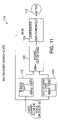
- FIG. 30is a diagram of a communication system that synchronizes clocks using a synchronization flag.
- FIG. 31shows a graph of a single timing pulse used for synchronizing a remote clock.
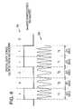
- FIG. 32shows a graph of a synchronization flag used for synchronizing a remote clock.
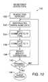
- FIG. 33is a flow diagram showing how network delay is determined using the synchronization flag.
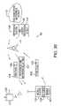
- FIG. 34is a diagram of a synchronization packet.
- a wireless communications network 12includes a cell phone 14 that receives voice signals 22 from a user 23 .
- a voice coder (vocoder) 18 in the cell phone 14encodes the voice signals 22 into encoded digital voice signals 31 that are then transmitted over a wireless digital radio channel 34 (cell call).
- the cell phone 14transmits the encoded voice signals 31 to a cellular communications site (cell site) 36 that relays the cell call to a Cellular Telecommunications Switching System (CTSS) 38 .
- CTSCellular Telecommunications Switching System
- the CTSS 38either connects the cell call to another cell phone either in the wireless cellular network 12 , to a landline phone on a PSTN network 42 as a circuit switched call or routes the cell call over a packet switched Internet Protocol (IP) network 46 as a Voice Over IP (VoIP) call.
- IPInternet Protocol
- VoIPVoice Over IP
- the cell callcan also be routed from the PSTN network 42 back to the cellular network 12 or from the PSTN network 42 to the IP network 46 , or visa versa.
- the cell calleventually reaches a telephone 44 that corresponds with a destination phone number originally entered at the cell phone 14 .
- Additional datacould be inserted at any point in the cellular network 12 , such as in PSTN network 42 and IP network 46 and the signal remodulated for transmission over wireline or cellular networks.
- Such datacould be system related such as routing information, toll or tariff information, etc.
- An In-Band Signaling (IBS) modem 28enables cell phone 14 to transmit digital data 29 from a data source 30 over the radio channel 34 of the cellular network 12 .
- the IBS modem 28modulates the digital data 29 into synthesized digital data tones 26 .
- the digital data tones 26prevent the encoding components in the cellular network 12 and landline network 42 , such as vocoder 18 , from corrupting the digital data.
- the encoding and modulation scheme used in the IBS modem 28allows digital data 29 to be transmitted through the same voice coder 18 used in the cell phone 14 for encoding voice signals 22 . Any appliance such as a vending machine, etc could be enhanced by this technology.
- Synthesized tonesare defined as signals that represent digital data that also have signaling characteristics that enable the signals to be encoded and decoded by a voice codec without losing the digital data information in the signal.
- Frequency Shift Keying (FSK) signalsare used to created the synthesized tones at different frequencies within the audio range of human speech.
- the IBS modem 28enables voice signals 22 and digital data 29 to be transmitted over the same digital audio channel using the same cell phone circuitry. This prevents a user from having to transmit digital data using a separate wireless modem and enables a cell phone user to talk and send data during the same digital wireless call.
- the inventionmodulates the digital data 29 into synthesized audio tones. This prevents the cell phone vocoder 18 from filtering or corrupting the binary values associated with the digital data 29 .
- the same cell phone transceiver and encoding circuitryis used for transmitting and receiving both voice signals and digital data. This enables the IBS modem 28 to be much smaller, less complex and more energy efficient than a standalone wireless modem. In some embodiments, the IBS modem 28 is implemented entirely in software using only the existing hardware components in the cell phone 14 .
- One or more servers 40are located at any of various locations in the wireless network 12 , PSTN network 42 , or IP network 46 .
- Each server 40includes one or more IBS modems 28 that encode, detect and decode the digital data 29 transmitted and received over the digital radio channel 34 . Decoded digital data is either processed at the server 40 or routed to another computer, such as computer 50 .
- a first transmitting portion of the IBS modem 28includes an IBS encoder 52 and a Digital to Analog converter (D/A) 54 .
- the IBS encoder 52is typically implemented using a Digital Signal Processor (DSP).
- DSPDigital Signal Processor
- the data source 30represents any device that requires wireless transmission or reception of digital data.
- the data source 30can be a laptop computer, a palm computer or a Global Positioning System (GPS) (see FIG. 15 ).
- GPSGlobal Positioning System
- the data source 30outputs a digital bit stream 29 to the IBS encoder 52 .
- the IBS encoder 52converts the digital data 29 into IBS packets specially formatted for transmission over a digital wireless voice channel.
- the IBS encoder 52then converts the bits from the IBS packets into digital data tones that are then fed into the D/A converter 54 .
- the IBS modem 28outputs binary values that each represent an amplitude and phase component of an audio tone.
- the D/A converter 54converts these digital values into analog audio tones 26 that are then output to an auxiliary audio port 15 on the cell phone 14 .
- the analog audio tones 26are then processed by the cell phone 14 .
- An Analog to Digital (A/D) converter 16 in the cell phone 14encodes the synthesized analog audio tones 26 into digital values.
- the vocoder 18encodes the digital representations of the synthesized tones 26 into encoded digital data 32 and outputs the encoded data to a transceiver 19 that transmits the encoded digital data 32 over the radio channel 34 .
- the preferred voltage of the synthesized audio tones 26 output from the D/A converter 26is around 25 millivolts peak to peak. This voltage level was discovered to prevent the audio tones 26 from saturating the voice channel circuitry in cell phone 14 .
- the IBS modem 28can be installed as an after market device that can connect any data source 30 to the cell phone 14 .
- the data source 30can transmit digital data 29 in any digital format.
- the digital data 29can be sent over an RS-232 interface, Universal Serial Bus (USB) interface, or any other serial or parallel interface.
- USBUniversal Serial Bus
- FIG. 3shows an alternative embodiment of the IBS modem 28 .
- the IBS modem 28 in FIG. 3is located inside the cell phone 14 and is implemented in software using the existing cell phone processor or using some combination of its own components and the existing cell phone components.
- the cell phone 14may include a data port 56 that receives the digital data 29 from the external data source 30 .
- the digital data source 30is internal to the cell phone 14 .
- the data source 30may be a Global Positioning System (GPS) chip that includes a GPS receiver (not shown) for receiving global positioning data from GPS satellites ( FIG. 14 ).
- GPSGlobal Positioning System
- the IBS encoder 52 in FIG. 3 as mentioned aboveis typically implemented in software using a DSP and may use the same DSP used for implementing the vocoder 18 .
- the D/A converter 54outputs the synthesized audio tones representing digital data 29 to the internal A/D converter 16 of the cell phone 14 .
- the IBS encoder 52in an alternative embodiment, not only synthesizes the digital data 29 into audio tones but also quantizes the digital frequency values.
- the IBS encoder 52then outputs the quantized data 55 directly into the vocoder 18 .
- the IBS encoder 52is implemented entirely in software in the same DSP that implements the vocoder 18 .
- the vocoder 18uses a specific encoding scheme associated with the wireless communications network 12 ( FIG. 1 ).
- the vocoder 18could be a VCELP encoder that converts voice signals into digital CDMA signals.
- the A/D converter 16 , D/A converter 54 and transceiver 19are existing cell phone components known to those skilled in the art.
- the IBS encoder 52enables the digital data 29 to be transmitted using the same cell phone circuitry that transmits voice signals.
- the IBS encoder 52prevents any signal approximation, quantization, encoding, modulation, etc. performed by the, A/D converter 16 , vocoder 18 , or transceiver 19 from corrupting or filtering any bits from the digital data 29 .
- FIG. 4is a detailed diagram of the IBS encoder 52 shown in FIG. 2 and FIG. 3 .
- a data buffer 58stores the binary bit stream 29 from the data source 30 .
- a packetizer 60segments the bits in buffer 58 into bytes that comprise a IBS packet payload.
- a packet formatter 62adds a packet preamble and postamble that helps prevent corruption of the IBS packet payload.
- An IBS modulator 64then modulates the bits in the IBS packet with two or more different frequencies 66 and 68 to generate digital data tones 69 .
- Cell phone voice codersincrease bandwidth in voice channels by using predictive coding techniques that attempt to describe voice signals without having to send all the information associated with human speech. If any unnatural frequencies or tones are generated in the voice channel (i.e., frequencies representing digital data), those frequencies might be thrown out by the voice coder 18 ( FIG. 2 ). For example, if the amplitude of the digital data tones are greater than that of normal voice signals or the same digital data tone is generated for too long a time period, the voice coder 18 might filter out that high amplitude or extended frequency signal. Depending on how the digital data tones are encoded, the digital bits represented by those unnatural audio tones may be partially or entirely removed from the voice channel.
- the IBS encoder 52encodes the digital data 29 in a manner where voice coders will not filter or corrupt the tones representing digital data.
- the IBS encoder 52does this by controlling the amplitudes, time periods and patterns of the synthesized audio tones used to represent the binary bit values.
- the packet formatter 62adds a packet preamble 73 and a header 75 to the front of a IBS packet 70 .
- the packet preamble 73includes a preamble pattern 72 and a sync pattern 74 .
- a checksum 78 and a packet postamble 79are attached to the backend of the IBS packet 70 .
- FIG. 6shows the synthesized digital data tones 69 output from the IBS modulator 64 ( FIG. 4 ).
- the IBS modulator 64( FIG. 4 ) converts the digital bits in the IBS packet 70 into one of two different tones.
- a first toneis generated at an f 1 frequency and represents a binary “1” value and a second tone is generated at a f 2 frequency and represents a binary “0” value.
- the f 1 frequencyis 600 Hertz and the f2 frequency is 500 Hertz (Hz).
- the IBS modulator 64includes Sine and Cosine tables that are used to generate the digital values that represent the different amplitude and phase values for the f 1 and f 2 frequencies.
- the digital datais output on the radio channel 34 at a baud rate of 400 bits/second. This baud rate has been found to be effective in preventing corruption of the digital audio data by a wide variety of different cellular telephone voice coders.
- the sine waves for each f 1 and f 2 tonebegin and end at a zero amplitude point and continue for a duration of 10 milliseconds. Eighty samples are generated for each digital data tone.
- an Automatic Gain Controller (AGC) 80is one encoding function used in the cell phone 14 .
- the AGC 80may be software that is located in the same DSP that implements the voice coder 18 .
- the AGC 80scales instantaneous energy changes in voice signals. There are situations when no voice signals have been fed into the AGC 80 for a period of time followed by a series of audio tones 82 that comprise the beginning of a IBS packet 70 .
- the AGC 80scales the first group of tones 82 at the beginning of the IBS packet 70 .
- the AGC 80also looks ahead at the zero signal levels 84 after the end of the IBS packet 70 , and will scale the tones 83 at the end of the IBS packet 70 as part of its prediction scaling scheme. This scaling prevents the over amplification of signal or noise when instantaneous energy changes occur in the voice channel.
- the “1” and “0” bits of the IBS packet 70are represented by tones f 1 and f 2 , respectively. If these tones are scaled by the AGC 80 , the digital bits represented by those frequencies might be dropped during encoding. For example, the vocoder 18 may see the scaled tones as noise and filter them from the audio channel. To prevent the unintentional filtering of tones that represent digital data, the IBS packet 70 in FIG. 5 includes preamble bits 72 and postamble bits 79 .
- the preamble bits 72 and postamble bits 79do not contain any of the digital data bits 29 from the data source but include a certain number of sacrificial bit(s) that are not needed for detecting or encoding the IBS packet 70 .
- the tones that are generated for these sacrificial bits in the preamble and postamblecan be scaled or filtered by the AGC 80 without effecting any of the digital data contained in the IBS packet payload 76 .
- the bit pattern in the preamble 72 and sync pattern 74are specifically formatted to further prevent corruption of the packet payload 76 .
- a random sequence and/or an alternating “1”–“0” sequence of bitsis used in either the preamble 72 and/or sync pattern 74 .
- These alternating or random bit patternsprevent adaptive filters in the cell phone vocoder 18 ( FIG. 2 ) from filtering tones representing the remaining bits in the IBS packet 70 .
- adaptive filtersadapt around the frequencies that are currently being transmitted over the wireless network. For example, if a long period of the same f 1 tone is currently being transmitted, an adaptive filter used in the cell phone may adapt around that f 1 frequency spectrum as shown by filter 86 .
- Another short tone at another frequency f 2may immediately follow the long period of f 1 tones. If the filter 86 is too slow to adapt, the first few f 2 tones may be filtered from the voice channel. If the filtered f 2 tone represent bits in the IBS bit stream, those bits are lost.
- some portion of the preamble 73includes a random or alternating “1”–“0” bit pattern. This preconditions the adaptive filter as shown by filter 88 .
- the preamble 73( FIG. 5 ) tries to include a portion of the same bit sequence that is likely or does occur in the packet payload 76 .
- the IBS encoder 52can look ahead at the bit pattern in the payload 76 .
- the encoder 52can then place a subset of bits in a portion of the preamble to represent the sequence of bits in the packet payload.
- the adaptive filteris less likely to filter out the tones that actually represent the digital data that is being transmitted.
- FIG. 9is a block diagram of receive circuitry 91 that receives the voice and data signals in the radio channel 34 .
- the IBS modem 28also includes an IBS decoder 98 the detects and decodes the digital data tones transmitted in the radio channel 34 .
- the receive circuitry 91is located at the CTSS 38 ( FIG. 1 ) that receives wireless transmissions from the cell sites 36 ( FIG. 1 ). The same receive circuitry 91 is also located in the cell phone 14 .
- the decoder part of the IBS modem 28can be external to the cell phone 14 or can be inside the cell phone 14 .
- Dashed line 104shows an IBS modem 28 external to a cell phone and dashed line 106 shows an internal IBS modem 28 internal to a cell phone.
- IBS modems 14can be located at any telephone location in the PSTN network 42 or IP network 46 ( FIG. 1 ).
- the receiving circuitry 91may be different when the IBS modem 28 is coupled to a landline. However, the IBS modem 28 operates under the same principle by transmitting and receiving synthesized tones over the voice channel of the phone line.
- the signals in radio channel 34are received by a transceiver 90 .
- a vocoder 92decodes the received signals.
- the vocoder 92may decode signals transmitted in TDMA, CDMA, AMPS, etc.
- a D/A converter 94then converts the digital voice signals into analog signals.
- the analog voice signalsare then output from an audio speaker 17 .
- a A/D converter 96converts the analog signals back into digital signals.
- the IBS decoder 98demodulates any tones representing digital data back into a digital IBS packets.
- a packet disassembler 100disassembles the packet payload from the IBS packets 70 and stores the decoded digital data in a data buffer 102 .
- FIG. 10is a state diagram explaining how the IBS decoder 98 in FIG. 9 operates.
- the IBS decoder 98repeatedly samples and decodes the audio signals received from the radio channel 34 .
- State 110searches for tones in the audio signal that represent digital data. If the Signal to Noise Ratio (SNR), for tones within the frequency range of the digital data tones, are greater than a preselected value, the IBS decoder 98 goes into an active state 112 .
- the active state 112collects tone samples. If at any time during the active state 112 the SNR falls below an active threshold value or a timeout is reached before enough tone samples are collected, the IBS decoder 98 returns to the search state 110 and begins again to search for digital data tones.
- SNRSignal to Noise Ratio
- the IBS decoder 98looks for bits that identify the preamble 73 in the IBS packet 70 ( FIG. 5 ). If the preamble 73 is detected, the IBS decoder 98 moves to clock recovery state 114 . The clock recovery state 114 synchronizes with the synchronization pattern 74 in the IBS packet 70 ( FIG. 5 ). The IBS decoder 98 then demodulates the packet payload 76 in state 116 . If the preamble 73 is not found, IBS decoder 98 goes back to the search state 110 and starts searching again for the beginning of an IBS packet 70 .
- the IBS decoder 98demodulates all of the packet payload 76 and then performs a checksum 78 as a final verification that a valid IBS packet 70 has been successfully demodulated. Control then returns back to the search state 110 and begins searching for the next IBS packet 70 .
- FIG. 11is a detailed diagram for the search state 110 of the IBS decoder 98 .
- the search state 110uses in band and out of band filtering. “In band” is used in the following discussion to refer to tones within the frequency range of the two tones that represent the digital data binary “1” value (500 Hz) and the digital data binary “0” value (600 Hz).
- a first band pass filter 118(in band) measures energy for signals in the audio channel within the frequency range of about 400 Hz to around 700 Hz.
- a second band pass filter 120(out of band) measures the energy in the audio channel for signals outside of the 400 Hz–700 Hz range.
- a Signal to Noise Ratio (SNR)is calculated in block 122 between the in band energy and the out of band energy. If tones representing the digital data exist in the audio channel, the energy measured by the in band filter 118 will be much greater then the energy measured by the out of band filter 120 .
- the IBS decoder 98determines the tones represent in band digital data. When digital data is detected, the IBS decoder 98 moves into the active state 112 ( FIG. 10 ) to begin searching for the beginning of an IBS packet 70 .
- FIG. 12shows the active state 112 for the IBS decoder 98 .
- Block 130is notified by the search state 110 when an in band tone is detected in the audio channel.
- Samples of the audio tonesare windowed in block 132 with a number of samples associated with a single binary bit. In one embodiment, 80 samples of the digital data tone are taken, padded with zeros, and then correlated with Discrete Fourier Transforms (DFTs).
- DFTsDiscrete Fourier Transforms
- a first DFThas coefficients representing a 500 Hz tone and is applied to the windowed data in block 134 .
- the first DFTgenerates a high correlation value if the samples contain a 500 Hz tone (“0” binary bit value).
- a second DFTrepresents a 600 Hz tone and is applied to the windowed samples in block 136 .
- the second DFTgenerates a high correlation value if the windowed samples contain a 600 Hz tone (“1” binary bit value).
- Block 138selects either a binary “0” or binary “1” bit value for the windowed data depending on which of the 500 Hz DFT or 600 Hz DFT yields the largest correlation value.
- the IBS decoder 98 in decision block 140continues to demodulate the tones until the preamble of the IBS packet 70 has been detected.
- the IBS decoder 98then moves to clock recovery state 114 ( FIG. 13 ) to synchronize with the sync pattern 74 in the IBS packet 70 ( FIG. 5 ). If more bits need to be demodulated before the preamble 73 can be verified, decision block 140 returns to block 132 and the next 80 samples of the digital data tones are windowed and demodulated.
- FIG. 13describes the clock recovery state 114 for the IBS decoder 98 .
- the clock recovery state 114demodulates the next string of bits associated with the sync pattern 74 ( FIG. 5 ).
- the clock recovery state 114aligns the tone samples with the center of the correlation filters described in the active state 112 . This improves decoder accuracy when demodulating the IBS packet payload 76 .
- Decision block 142looks for the sync pattern 74 in the IBS packet 70 . If after demodulating the next tone, the sync pattern 74 is not found, decision block 142 offsets the window used for sampling the sync pattern 74 by one sample in block 148 . Decision block 150 then rechecks for the sync pattern 74 . If the sync pattern 74 is found, decision block 144 determines the power ratio for the detected sync pattern. This power ratio represents a confidence factor of how well the demodulator is synchronized with the sync pattern. The power ratio is compared with the power ratios derived for different window shifted sampling positions. If the power ratio is greater then a previous sampling position, then that power ratio is saved as the new maximum power ratio in block 146 .
- the decoder in block 148offsets the sampling window by one sample position. The power ratio is then determined for the shifted window and then compared to the current maximum power ratio in decision block 144 . The window is shifted until the maximum power ratio is found for the sync pattern 74 . The window offset value at the maximum power ratio is used to align the demodulator correlation filters with the center sample of the first bit 77 ( FIG. 5 ) in the IBS packet header 75 .
- the IBS decoder 89then jumps to demodulate state 116 ( FIG. 10 ) where the identified window offset is used to demodulate the remaining 500 and 600 Hz tones that represent the packet payload bits 76 and check sum bits 78 .
- the demodulation state 116correlates the f 1 and f 2 tones with DFTs in the same manner as in the active state ( FIG. 12 ).
- the check sum bits 78are then used as a final check to verify that a valid IBS packet has been received and accurately decoded.
- FIG. 14is a diagram of the IBS modem 28 located in a battery pack connected to the cellular telephone 14 .
- a hands free audio channel pin 200couples the IBS modem 28 to the voice channel 202 in the cell phone 14 .
- a switch 204couples either voice signals from the microphone 17 or digital data tones from the IBS modem 28 to the voice channel 202 .
- the switch 204is controlled either through a menu on a screen (not shown) in the cell phone 14 or by a button 206 that extends out of the back end of the battery pack 208 .
- the switch 204can also be controlled by one of the keys on the keyboard of the cell phone 14 .
- the button 206can also be used to initiate other functions provided through the IBS modem 28 .
- a Global Positioning Systemincludes a GPS receiver 210 located in the battery pack 208 .
- the GPS receiver 210receives GPS data from a GPS satellite 212 .
- a cell phone operatorsimply pushes button 206 during an emergency situation. Pressing the button 206 automatically enables the GPS receiver 210 to collect GPS data from GPS satellite 212 .
- the switch 204connects IBS modem 28 on the voice channel 202 of the cell phone 14 .
- the IBS modem 28is then activated. As soon as the GPS data is collected in the IBS modem 28 , the data is formatted, encoded and output by IBS modem 28 to the voice channel 202 of the cell phone 14 .
- the user 23can push the button 206 anytime after manually calling up a phone number. After the audio channel is established with another endpoint, the user 23 pushes button 206 .
- Switch 204is connected to the IBS modem 28 and the IBS modem 28 is activated.
- the GPS data(or other digital source) is then sent as digital data tones through the IBS modem 28 to an endpoint over the established audio channel. After the data has been successfully transmitted, the user presses button 206 again reconnecting switch 204 to the audio receiver 17 .
- FIG. 15shows the different types of data sources that can be connected to the IBS modem 28 .
- Any one of a palm computer 212 , GPS receiver 214 or a computer 216 , etc.can are coupled to the IBS modem 28 .
- the IBS modem 28converts the bits output from the device into digital data tones that are then output over the radio channel 34 in the wireless network. Because data can transmitted to another endpoint through the cell phone 14 , none of the devices 212 , 214 or 216 need a separate wireless modem.
- the IBS modemcan be implemented in a standard computer sound card.
- a sound card 252such as a Sound Blaster card manufactured by Creative Labs, Inc., 1523 Cimarron Plaza; Stillwater, Okla. 74075 is included in a computer 250 .
- a speaker output 253 of the sound card 252outputs audio tones to a hands free port 257 on a cell phone 258 .
- a microphone input 259 on the sound card 252is connected to the speaker output of the cell phone 258 .
- the computerincludes a processor 254 that converts digital data into an audio format used by the sound card 252 to output synthesized audio tones.
- the cell phone 258encodes and transmits those audio tones over the voice channel of a wireless communications network.
- a cell site 261receives the transmitted audio tones and forwards the audio tones over a PSTN network 263 .
- a computer 262is connected to a telephone line 260 at the destination location of the phone call.
- Another sound card 264 and a processor 266 in computer 262demodulate the audio tones back into digital data.
- the digital data represented by the audio tonesare displayed on computer 262 .
- the sound cardsmay be used for data encoding, decoding or both.
- the sound cardsmay be used at computer 250 , computer 262 , or both.
- data files, GPS data, data entered by the keyboard by a user, or any other digital datais packetized and formatted by computer 250 into IBS packets in block 270 .
- Packetization and packet formattingis described in FIGS. 4 and 5 .
- the binary bit values in the IBS packetsare converted in block 272 into a digital format used by the sound card 252 ( FIG. 16 ) for generating synthesized audio tones.
- binary “1” bit values in the IBS packetare converted into a digital format representing a first f 1 frequency tone and binary “0” bit values are converted into a second f 2 frequency tone.
- the f 1 and f 2 tonesare generated similar to the manner described in FIG. 6 .
- the sound card in block 274outputs analog tones representing the binary bit values in a manner similar to the IBS encoder 52 and the digital to analog converter 54 described in FIG. 3 .
- the cell phone in block 276encodes the audio tones and transmits the encoded audio tones over the voice channel in the wireless communications network in block 278 .
- the cellular phone callis established with a destination phone number.
- either a user picks up the ringing phone line or the computer 262 ( FIG. 16 ) at the destination end of the cellular phone callis programmed to detect a ringing signal from the telephone line 260 . If a ring signal is detected, either a user or the computer 262 in block 282 generates an “hook-off” signal on the telephone line 260 .
- the sound card 264 in block 284acts like an analog to digital converter by converting the audio tones on the telephone line 260 into digital data.
- the sound card 264in conjunction with the processor 266 ( FIG. 16 ) decodes the IBS audio tones similar to the IBS decoder 98 described in FIGS. 9–13 .
- the digital representations of detected IBS tonesare then displayed on the screen of computer 262 in block 290 .
- a userwants to find the location for cell phone 258 .
- the userdirects computer 262 ( FIG. 16 ) to dial the phone number for cell phone 258 .
- the computer 262uses the sound card 264 to send IBS tones that direct cell phone 258 to send back GPS location data.
- the computer 250may have a GPS receiver or the cell phone 258 may have a standalone GPS receiver. If the GPS receiver and the IBS modem are internal to the cell phone 258 as shown in FIGS. 2–9 , the computer 250 does not need to be connected to the cell phone 258 .
- the GPS datais converted into IBS tones either by the sound card 252 as described in FIG. 17 or through an internal IBS modem as described in FIGS. 2–9 .
- the IBS tones representing the GPS dataare transmitted back over the wireless telecommunications channel and the PSTN network 263 to the telephone line 260 .
- the sound card 264 in computer 262monitors the phone line 260 for the IBS audio tones. When detected, the IBS tones are converted back into digital GPS data and displayed by processor 266 to the user on the screen of computer 262 .
- a mapping process in the computer 262may then convert the GPS longitude and latitude values into a state, city and street address.
- FIG. 19shows an alternative technique for demodulating and synchronizing the IBS modem in the IBS decoder 300 .
- the IBS audio tonesare received over the voice channel of the wireless communications network at interface 301 .
- the received tonesare converted from analog to digital form by A/D converter 302 .
- the IBS signal detector 304detects the presence of the IBS audio tones in the same manner as described in FIG. 11 .
- the alternative synchronization techniquebegins with the decoder 300 tuning the IBS signals to complex basebands with multipliers 306 and 308 .
- Multiplier 306effectively moves any IBS tones at the first and second IBS frequencies f 1 and f 2 to DC.
- This first baseband signalis referred to as S A ′ and the second baseband signal is referred to as S B ′.
- a matched filter bank 310applies matched filters to the baseband signals having the expected pulse shapes for the two audio tones representing the binary “1” and binary “0” values.
- the S A signal output from the matched filter bank 310represents a binary 1 value and the S B signal represents a binary 0 value.
- the matched filter bankcan also add filtering to account for known characteristics of the wireless communications channel that may exist in the S A or S B signals.
- the matched filteris selected to match the pulse shaping applied to the modulator.
- the pulse shapingis selected for the best trade-off between signaling bandwidth, bit rate and inter symbol interference.
- the pulse shaping filteris applied to the integrated phase of the modulator's numerical oscillator.
- An IBS synchronizer 312aligns the modulator with the synchronization pattern attached to the front of the IBS packet. Segments 316 of samples from the S A and S B signals are input to synchronization demodulator 314 along with a sample start time T B .
- the demodulator 314outputs a power value 320 to the IBS synchronizer 312 that indicates how closely the demodulator is synchronized with the beginning bit in the synchronization pattern.
- the IBS synchronizer 312uses the power values 320 for each sample start time T B to determine the optimum synchronization start time (*T B ) for demodulating the remaining bits in the IBS packet.
- IBS packet modulator 322uses the optimum start time *T B to demodulate the binary bit values from the S A and S B signals.
- FIG. 20is a more detailed description of the sync demodulator 314 and the IBS packet demodulator 322 in FIG. 19 .
- a first integrator 324integrates the first segment of samples for the S A signal. The integrator starts at sample start time T B and integrates N number of samples representing the duration T of one IBS bit (Baud time).
- a rectifier 326feeds the magnitude of the integration value into an adder 332 .
- an integrator 328integrates the segments of samples for signal S B starting at sample start time T B .
- a rectifier 330feeds the magnitude of the integrated segment of the S B signal into adder 332 .
- the output of adder 332is a power signal 320 that is fed back to the synchronizer 312 .
- the IBS packet demodulator 322( FIG. 19 ) also includes a comparator 334 that generates either a binary 1 value or a binary 0 value according to the magnitudes of the S A and S B signals.
- FIG. 21shows a representation of the signals S A and S B that are output from the matched filter bank 310 .
- a number of samples 336 of the S A or S B signalrepresent the bit duration T of one IBS tone. In the example shown in FIG. 21 , five samples are taken for each bit duration T.
- the sample start time T Bis shifted one sample for each integration. A starting sample for the first integration starts at sample start time T b1 . As seen in FIG. 21 , the sample start time T b1 is not aligned with the S A signal representing a binary “1” value or the S B signal representing a binary “0” value.
- the sync demodulator 314 in FIG. 20generates a power output value of 0.0 for T b1 .
- sample start time T B2When sample start time T B2 is used, the demodulator 314 generates an output value of ⁇ 2.0.
- the sample start time T B3represents the sample with the best synchronization with the beginning of the “0” tone in signal S B .
- the output poweris ⁇ 3.
- FIG. 22shows the magnitude of the power distribution for the different sample start times. The maximum power magnitude is identified at sample start time T B3 .
- the optimal sample start time T b3is used by the IBS synchronizer 312 ( FIG. 19 ).
- a first sampling segment 338 starting at sample time T b3generates an output value from adder 332 in FIG. 20 of ⁇ 3.
- the comparator 334 in FIG. 20generates a binary “0” value for any adder value less than zero.
- the output of adder 332 for a second segment of sample values 340generates an output value of +3. Because the output value for the second sample segment is greater than 0, comparator 334 generates a binary “1” value.
- the IBS packet demodulator 322( FIG. 19 ) continues to decode the tones in the S A and S B signals for the remainder of the IBS bit stream.
- FIG. 23shows a variation of the synchronization scheme described in FIGS. 19–22 .
- the IBS tonesare detected in block 341 .
- the IBS tonesare shifted to baseband by the multipliers 342 for both the audio tone frequency f A representing a binary bit “1” value and for the audio tone f B representing a binary bit “0”.
- the baseband shiftis done for each individual sample T(x) of the f A and f B signals
- a running sum of the latest baud valueis taken using the new sample T(x) in block 344 .
- the 21 st sample T(N+1)is deleted from the running sum and the next sample T(x) is added to the running sum.
- the magnitude of the two running sums for tone A and tone Bare each taken in blocks 345 and compared by comparator 346 .
- a binary “1” or binary “0” valueis output from comparator 346 depending upon which of the A tone or B tone samples has the largest magnitude value.
- the binary bit values output from comparator 346are correlated with the known sync pattern in the correlation block 347 .
- the selected sample start time *T Bis identified as the last sample that generates the largest correlation value with the synchronization pattern.
- the remaining bits in the IBS packetare then demodulated according to the selected sample start time *T B .
- FIG. 24shows the encoder portion 350 of a Multichannel Inband Signaling (MIBS) modem.
- a data source 351generates a binary bitstream.
- the MIBS encoder 350generates multiple inband signaling channels within the same voice channel.
- a data buffer 352stores the binary bit stream from the data source 351 .
- a packet assembler 353assembles the bits in buffer 352 into a packet payload and adds a preamble and postamble to the packet payload to form IBS packets as described above in FIG. 4 .
- the encoder 350includes two modulators 356 and 362 that each generate different audio tones that represent the bits in the IBS packets.
- Modulator 356modulates binary “1” values using an f 1 frequency 360 and modulates binary “0” values using an f 2 frequency 358 .
- Modulator 362modulates other bits in the IBS packets having binary “1” values using an f 3 frequency 364 and modulates binary “0” values using an f 4 frequency 366 .
- the f 1 and f 2 tones output from modulator 356are referred to as a first Inband Signaling channel and the f 3 and f 4 tones output from modulator 362 are referred to as a second IBS channel.
- the tones output from the two modulators 356 and 362are combined together by an adder 368 and then output to the D/A converter 370 and other cell phone circuitry 14 ( FIG. 2 ).
- the cell phone circuitry 14encodes and transmits the tones in the two IBS channels over an audio channel of the cellular telephone network.
- Each of the individual modulators 356 and 366are similar in operation to the IBS modulator 64 shown in FIG. 4 .
- Any number of IBS channelscan be generated in the IBS modem 24 .
- a third IBS channelcould be provided by adding a third IBS modulator that modulates bits for a third portion of the IBS packets into tones using frequencies f 5 and f 6 .
- the output of the third IBS modulatorwould be fed into the adder 368 .
- only a two channel IBS modem with two corresponding IBS modulators 356 and 362are shown in FIG. 24 .
- An IBS channel controller 354controls how the multiple IBS channels are utilized by the transmitting and receiving IBS modems. For example, a first IBS channel may only be used by a first IBS modem for transmitting IBS packets and a second IBS channel may only be used by that first IBS modem for receiving IBS packets. A second IBS modem on the opposite end of the transmission then uses the second IBS channel for transmission and uses the first IBS channel for reception.
- the IBS channel controller 354adds control bits into the IBS packets that negotiate use of the multiple IBS channels between the two communicating IBS modems. The different configurations for the IBS modems are described in further detail below in FIGS. 26 and 27 .
- the controller 354also controls what portions of the IBS packets are modulated by modulators 356 and 362 . For example, the modulators may modulate every other IBS packet or each modulator may modulate different portions of the same IBS packets.
- FIG. 25shows the decoder 375 of the MIBS modem.
- the audio tones from the audio channelare decoded by receiving circuitry 372 and fed into an A/D converter 374 .
- a first filter 376filters signals outside a frequency range of the two tones in the first IBS channel and a second filter 378 filters signals outside the frequency ranges of the two tones in the second IBS channel.
- the frequency range of filter 376is from f 1 ⁇ f to f 2 + ⁇ f and the frequency range of filter 378 is from f 3 ⁇ f to f 4 + ⁇ f.
- the filters 376 and 378are shown before the decoders 380 and 382 , respectfully. However, the filters 376 and 378 can be implemented in the same DSP anywhere in the decoding process.
- a first IBS channel decoder 380detects and demodulates the two tones in the first IBS channel into binary bit values and a second IBS channel decoder 382 detects and demodulates the two tones in the second IBS channel into binary bit values.
- the decoders 380 and 382detect, synchronize, and demodulate the IBS tones in the same manner as previously described for decoder 98 in FIG. 9 or decoder 300 in FIG. 19 .
- a packet assembler 386assembles the bits output from the two decoders 380 and 382 into IBS packets that are then output to a data buffer 388 .
- the IBS channel controller 384 in the receiving IBS modemsynchronizes the two decoders 380 and 382 and determines which decoders demodulate what portions or which IBS packets.
- the controller 384also conducts a communication protocol with the transmitting IBS modem that negotiates which IBS modem is transmitting and which IBS modem is receiving IBS packets over which IBS channels.
- the filter 376 and decoder 380 for the first IBS channel and the filter 378 and decoder 382 for the second IBS channelcan be implemented in software in the same DSP.
- one DSPcan be used for each individual channel encoder and decoder in each MIBS modem.
- MIBSMagnetic Infrared
- FIG. 26shows one possible configuration for two Multichannel Inband Signaling (MIBS) modems 390 and 396 .
- the two IBS channels 398 and 400are transmitted from MIBS modem 390 over the voice channel of a wireless communications network and then possibly through a landline telephone network to the MIBS modem 396 .
- the two MIBS modems shown in FIG. 26operate in a half duplex mode where one of the IBS modems transmits IBS packets over both the first IBS channel 398 and the second IBS channel 400 at the same time.
- the second IBS modem 396is allowed to begin a transmission 394 back to modem 390 over the two IBS channels 398 and 400 .
- the MIBS modem 390sends information in one of the IBS packets indicating to the MIBS modem 396 that the transmission 392 is completed.
- FIG. 27shows an alternative configuration where the first IBS channel 398 is dedicated to transmitting IBS packets from MIBS modem 390 and the second IBS channel 400 is dedicated to transmitting packets from MIBS modem 396 .
- both MIBS modem 390 and 396can transmit and receive packets at the same time.
- This full duplex configurationcan provide faster communications for certain types of IBS transmissions.
- the MIBS modem 390may transmit different potions of the same IBS packets over the two IBS channels 398 and 400 or may alternate transmission of different IBS packets over the two IBS channels.
- one IBS channelmay be used for transmitting IBS packets and the second IBS channel may be used exclusively for signaling and protocol communications between the two MIBS modems.
- portions of bits from the same IBS packetsare interleaved in the two IBS channels or the same IBS packets are transmitted over both IBS channels for redundancy.
- the information in the two IBS channelscan be reconfigured according to the application associated with IBS packet data.
- a request to reconfigure the IBS channelscan be encoded into the IBS packet header.
- the IBS channel controller 354 ( FIG. 24 ) in MIBS modem 390may send an IBS packet to MIBS modem 396 that contains a reconfiguration request in the IBS packet preamble 73 ( FIG. 5 ).
- the reconfiguration request from modem 390may request both the first IBS channel 398 and the second IBS channel 400 and then request allocation of a third IBS channel 401 , with a slower baud rate, to MIBS modem 396 for transmitting acknowledge messages back to modem 390 .
- MIBS modem 390then waits for an acknowledge of the configuration request from modem 396 .
- the IBS channel controller 384( FIG. 25 ) in MIBS modem 396 reads the reconfiguration request in the IBS packet preamble. The controller 384 then outputs an acknowledge back through the encoder of MIBS modem 396 . The encoder formats the acknowledge into the preamble of a reply IBS packet that is then modulated and transmitted back to MIBS modem 390 over one or more of the currently allocated IBS channels. The controller in the modem 396 then reconfigures the encoder to receive IBS packets over the first and second IBS channels 398 and 400 and transmit packets over the third low baud rate channel 401 .
- the controllerdirects the encoder and the decoder in the modem 390 to transmit over the first and second IBS channels and receive from the low baud rate third channel.
- the two modems 390 and 396then transmits and receive IBS packets according to the new channel configuration.
- FIG. 28shows a Multicarrier Inband Signaling modem according to another aspect of the invention.
- the multichannel IBS modem described in FIGS. 24–27generates two different audio tones, one tone representing a binary “1” value and a second tone representing a binary “0” value.
- the two tonesare generated in a sequential tone stream over time to represent a binary bit stream.
- the multicarrier IBS modem in FIG. 28generates multiple audio tones at the same time, where each tone represents a different bit location in a four bit portion of the IBS packet.
- the particular audio tone associated with one of the four bit locationsrepresents a binary “1” value (or alternatively a binary “0” value). If the audio tone is not generated for a particular bit time (baud), the IBS decoder assumes the binary bit value associated with that bit location is “0”.
- a packet formatter 404formats those bits into an IBS packet.
- a first portion of one of the IBS packetscontains the bits “1010”.
- the packet formatter 404outputs each one of the four bits into a different one of the four modulators 406 , 408 , 410 and 412 .
- the first bit “1” of the four bit sequenceis referred to as bit B 1
- the second bit “0”is referred to as bit B 2
- the third bit “1” of the four bit sequenceis referred to as bit B 3
- the fourth bit “0”is referred to as bit B 4 .
- Modulator 406receives bit B 1 , modulator 408 receives bit B 2 , modulator 410 receives bit B 3 , and modulator 412 receives bit B 4 . Because bit B 1 is a binary “1” value, modulator 406 generates a tone at frequency f 1 during the first baud period. The modulator 408 does not generate an f 2 tone for the first baud period because the B 2 bit is a binary “0” value. Accordingly, modulator 410 generates a f 3 tone during the first baud period and modulator 412 does not generate a f 4 tone during the first baud period. The modulators work in essentially the same manner as the IBS modulator 64 in FIG. 4 except that a frequency tone is generated for the binary “1” values and no tone is generated for the binary “0” value.
- the f 1 and f 3 tonesare combined together by summer 414 .
- a digital to analog converter 416converts the digital signal into an analog signal that is fed into cell phone transmit circuitry 418 .
- the transmit circuitry 418transmits the audio tones over the voice channel of the cellular telephone network.
- FIG. 29shows the decoder for the multicarrier IBS modem.
- Receive circuitry 420receives the IBS tones from the voice channel of the cellular communications network.
- An A/D converter 422converts the audio tones into a digital signal.
- Four bandpass filters 424 , 426 , 428 and 430each are centered about the frequency for the tones f 1 , f 2 , f 3 , and f3, respectively.
- the tone representing the binary bit B 1passes through bandpass filter 424 while other tones, such as tone f 3 , are filtered by the bandpass filter f 1 .
- Decoder 432identifies the tone f 1 in a manner similar to the IBS decoder described in FIGS. 11–13 , only for a single tone. Because the f 1 tone was detected by decoder 432 , a binary “1” value is generated representing bit B 1 in the four bit sequence.
- Decoder 436detects an f 3 tone and accordingly generates a binary “1” value for bit B 3 .
- Decoder 438generates a binary “0” value for bit B 4 because no f 4 tone was generated by the multicarrier encoder.
- a packet assembler 440receives the four bits B 1 –B 4 and places them into the appropriate IBS packet location in the data buffer 442 .
- a communications network 99includes a mobile station 100 that includes a mobile clock 101 .
- the mobile station 100in one embodiment is a cellular telephone, or other type of mobile device, that includes a Global Positioning System (GPS).
- GPSGlobal Positioning System
- the mobile station 100receives global positioning data from satellite 102 .
- the mobile station 100receives position data from the satellite 102 and transmits the position data to a reference station 108 .
- the reference station 108may then forward the location data to another destination in a communications network 112 .
- the communications network 112can include a Public Services Telephone Network (PSTN) and an Internet Protocol (IP) network.
- PSTNPublic Services Telephone Network
- IPInternet Protocol
- the reference station 108or some other location in the communications network 112 , includes a reference clock 110 .
- Wireless radio communications between the mobile station 100 and the reference station 108may use either analog or digital signaling.
- the reference station 108 and the mobile station 100may transmit data or voice signals.
- a synchronization flag (sync flag) 104is used to synchronize the mobile clock 101 in the mobile station 100 with the reference clock 110 at reference station 110 .
- the sync flag 104contains a sequence of bits that are identified by the mobile station 100 .
- the sync flag 104is received by the mobile station 100 then sent back to the reference station 108 .
- the sync flag 104includes a reference bit 105 associated with a specific time when the sync flag was transmitted. After the synchronization flag 104 is returned by the mobile station 100 back to the reference station 108 , the IBS modem 28 in reference station 108 synchronizes with the returned sync flag 104 in one of the ways described in FIG. 13 or FIGS. 19–23 . The reference station 108 then identifies a final time associated with the returned reference bit 105 .
- the reference station 108can more accurately determine the network delay in communications system 99 .
- the round trip delayis defined as an amount of time required for the sync flag 104 to go from reference station 108 , to mobile station 100 and back to reference station 108 .
- the round trip delayis divided by two to derive the one-way network delay time.
- the network delay timecan then be subtracted from a reference time 107 by either the mobile station 100 or the reference station 108 to compensate for network delay.
- the mobile station 100uses the adjusted reference time to update the mobile clock 101 .
- the IBS modem 28 in the mobile station 100or the IBS modem 28 in reference station 108 , or both, may synchronize with the sync flag 104 and determine a reference time according to the reference bit.
- FIG. 31shows a single synchronization pulse 120 used for calculating network delay.
- Network delayis determined by calculating the amount of time required for the pulse 120 to go from the reference station, to the mobile station and then back at the reference station.
- the problem with using a single reference pulse 120is that the pulse may be distorted by encoding and decoding circuitry in the communications network.
- the reference pulse 120is transmitted over the same channel in the communications network used for transmitting and receiving voice signals.
- a voice codecmay filter out or further corrupt the reference pulse 120 .
- a reference pulse 122shows one example of distortion. Because pulse 122 is distorted, the mobile station and/or the reference station cannot accurately determine when the pulse 122 is received. This prevents an accurate determination of the network delay and prevent accurate synchronization of the mobile clock with the reference clock.
- a number of samples 123are taken by the reference station of the reference pulse 120 .
- the sample ratemay be some value such as 125 microseconds.
- a detected transition in the pulse 120 from a zero value to some threshold value,is identified as reference point 124 .
- the reference point 124is used by the reference station to calculate the network delay time.
- FIG. 32shows how the sync flag 104 prevents signal corruption from effecting the detected reference point and, in turn, effecting the calculated network delay time.
- a sequence of sync bitsare transmitted in the sync flag 104 .
- One of the bits in the sync flag 104is used as the reference bit 105 .
- An initial start time T o for the reference bit 105is tracked by the reference station. In the example shown in FIG. 32 , the transition from a “0” bit to the first “1” bit in the sync flag 104 is selected as the To reference point 132 .
- the IBS modemfirst synchronizes with the entire sync flag 104 as shown by block 130 .
- This modem synchronizationshifts a sample start time 136 for the entire sync flag 104 until an optimum power ratio is generated. By identifying an optimum power ratio for the entire sync flag 104 , a few corrupted samples in the sync flag 104 are less likely to adversely effect the detected location of reference point 132 .
- Dashed line 134represents signal corruption in the sync flag 104 . Because the IBS modem in block 130 synchronizes with multiple bits of the synchronization flag 104 , the corrupted samples 134 in the synchronization flag 104 do not offset where the reference point 132 is detected. In a general case, the reference point 132 will be no more then +/ ⁇ one half of the sample rate. In the example shown here, the reference point 129 will be off no more then +/ ⁇ 62.5 microseconds.
- multiple sync flags 104are sent. This ensures that the mobile station will detect at least one of the sync flags 104 .
- the reference timeis adjusted according to which sync flag is used.
- different tone frequenciesare generated by the IBS modem 28 to represent the binary “1” values and the binary “0” values in the sync flag 104 . These tones are transmitted over the audio channel of the communications network. This is described above in FIGS. 1–29 . By generating tones having frequencies within a human voice range, voice codecs in the communications network are less likely to corrupt or filter the binary bits represented by the generated tones.
- each sync flag 104has a sorter duration than the single synchronization pulse 120 shown in FIG. 31 . This provides a better signaling environment for properly passing the bits through digital voice coders in wireless networks. Thus, using the sync flag 104 instead of using a single sync pulse further reduces signal corruption.
- the sync flag 104is initially sent out by the reference station in step 140 .
- the mobile stationreceives the sync flag and then returns the sync flag back to the reference station in step 142 .
- the IBS modem in the reference stationsynchronizes with the returned sync flag in step 144 .
- the IBS modemsynchronizes with the sync flag by varying the sample start time (T B ) until the optimum power ratio for the synchronization flag is determined.
- block 146uses the optimum sample start time (*T B ) to determine the time associated with reference point 132 ( FIG. 32 ) in the sync flag.
- the time associated with the reference point 132is determined by multiplying the number of samples between the optimum sample start time (*T B ) and the reference point 132 by the sample rate.
- the time from when the reference bit was originally output by the reference station (T 0 ) to when the reference bit is received back by the reference station (T final )is the round trip delay time.
- Block 148determines the round trip delay and divides the round trip delay in half to determine the one way time delay in the network (network delay).
- the derived network delayis used in block 150 to synchronize the mobile clock 101 ( FIG. 30 ) or adjust any time dependant data in the network.
- a data packet 152is used for identifying network delay.
- a preamble 154identifies the packet 152 as a clock recovery packet.
- Payload data 156 in the clock recovery packet 152uses a preselected format and sequence of bits for modem synchronization. For example, the second bit 158 in the payload 156 is used as the reference bit.
- the IBS modemfirst synchronizes with the group of synchronization bits 160 in the payload 156 . An optimum sample start time is identified for the sync bits 160 . Then a reference time is determined according to the reference bit 158 in the synchronization bits 160 .
- Additional informationcan be incorporated into the packet 152 for more accurately identifying network delay.
- a second set of bits 162 in the payload 156identify the turn around time required by the mobile station 100 ( FIG. 30 ) to process the synchronization packet 152 .
- the mobile station 100determines when the packet 152 is first received.
- the mobile station 100then calculates when the packet 152 is transmitted back to the reference station 108 .
- the time from when the packet 152 is first received by the mobile station to when the reply packet is transmitted back to the reference stationis referred to as the turn around time.
- the turn around time 162can be subtracted from the round trip time to more accurately determine how long it takes a packet to travel between the reference station and the remote station.
- Bitscan be padded in payload 156 to ensure approximately the same turn around time for each synchronization packet 152 .
- other payload data 164can also be carried along with the sync bits 160 and 162 .
- the synchronization packet 152can be incorporated into a wider variety of network protocols since the timing communications are performed at one level higher than the synchronization flag scheme described in FIG. 30 .
Landscapes
- Engineering & Computer Science (AREA)
- Radar, Positioning & Navigation (AREA)
- Remote Sensing (AREA)
- Physics & Mathematics (AREA)
- General Physics & Mathematics (AREA)
- Computer Networks & Wireless Communication (AREA)
- Signal Processing (AREA)
- Mobile Radio Communication Systems (AREA)
Abstract
Description
Claims (14)
Priority Applications (1)
| Application Number | Priority Date | Filing Date | Title |
|---|---|---|---|
| US09/888,085US7164662B2 (en) | 1997-05-19 | 2001-06-22 | Network delay identification method and apparatus |
Applications Claiming Priority (11)
| Application Number | Priority Date | Filing Date | Title |
|---|---|---|---|
| US4703497P | 1997-05-19 | 1997-05-19 | |
| US4714097P | 1997-05-20 | 1997-05-20 | |
| US4836997P | 1997-06-03 | 1997-06-03 | |
| US4838597P | 1997-06-03 | 1997-06-03 | |
| US5549797P | 1997-08-12 | 1997-08-12 | |
| US09/230,079US6144336A (en) | 1997-05-19 | 1998-05-19 | System and method to communicate time stamped, 3-axis geo-position data within telecommunication networks |
| PCT/US1998/010317WO1998053573A2 (en) | 1997-05-19 | 1998-05-19 | System and method to communicate time stamped, 3-axis geo-position data within telecommunication networks |
| US11609399P | 1999-01-15 | 1999-01-15 | |
| US09/484,942US6771629B1 (en) | 1999-01-15 | 2000-01-18 | In-band signaling for synchronization in a voice communications network |
| US09/531,367US6690681B1 (en) | 1997-05-19 | 2000-03-21 | In-band signaling for data communications over digital wireless telecommunications network |
| US09/888,085US7164662B2 (en) | 1997-05-19 | 2001-06-22 | Network delay identification method and apparatus |
Related Parent Applications (2)
| Application Number | Title | Priority Date | Filing Date |
|---|---|---|---|
| US09/531,367Continuation-In-PartUS6690681B1 (en) | 1997-05-19 | 2000-03-21 | In-band signaling for data communications over digital wireless telecommunications network |
| US09/531,367ContinuationUS6690681B1 (en) | 1997-05-19 | 2000-03-21 | In-band signaling for data communications over digital wireless telecommunications network |
Publications (2)
| Publication Number | Publication Date |
|---|---|
| US20020015424A1 US20020015424A1 (en) | 2002-02-07 |
| US7164662B2true US7164662B2 (en) | 2007-01-16 |
Family
ID=27574328
Family Applications (1)
| Application Number | Title | Priority Date | Filing Date |
|---|---|---|---|
| US09/888,085Expired - Fee RelatedUS7164662B2 (en) | 1997-05-19 | 2001-06-22 | Network delay identification method and apparatus |
Country Status (1)
| Country | Link |
|---|---|
| US (1) | US7164662B2 (en) |
Cited By (36)
| Publication number | Priority date | Publication date | Assignee | Title |
|---|---|---|---|---|
| US20020097706A1 (en)* | 1997-05-19 | 2002-07-25 | Preston Dan A. | In-band signaling for data communications over digital wireless telecommunications networks |
| US20030152057A1 (en)* | 2002-02-12 | 2003-08-14 | Vivian Chou | Temporal alignment of CODEC data with wireless local area network RF slots |
| US20060262875A1 (en)* | 2005-05-17 | 2006-11-23 | Madhavan Sethu K | Data transmission method with phase shift error correction |
| US20070092024A1 (en)* | 2005-10-24 | 2007-04-26 | General Motors Corporation | Method for data communication via a voice channel of a wireless communication network |
| US20070190950A1 (en)* | 2006-02-15 | 2007-08-16 | General Motors Corporation | Method of configuring voice and data communication over a voice channel |
| US20070238456A1 (en)* | 2006-03-22 | 2007-10-11 | Mark Robins | Method for accurate time setting of communication device over the air and corresponding communication device |
| US7286522B2 (en) | 1998-05-19 | 2007-10-23 | Airbiquity, Inc. | Synchronizer for use with improved in-band signaling for data communications over digital wireless telecommunications networks |
| US20070258398A1 (en)* | 2005-10-24 | 2007-11-08 | General Motors Corporation | Method for data communication via a voice channel of a wireless communication network |
| US20080247484A1 (en)* | 2007-04-03 | 2008-10-09 | General Motors Corporation | Method for data communication via a voice channel of a wireless communication network using continuous signal modulation |
| US20080255828A1 (en)* | 2005-10-24 | 2008-10-16 | General Motors Corporation | Data communication via a voice channel of a wireless communication network using discontinuities |
| US20080273644A1 (en)* | 2007-05-03 | 2008-11-06 | Elizabeth Chesnutt | Synchronization and segment type detection method for data transmission via an audio communication system |
| US20090047904A1 (en)* | 2001-04-24 | 2009-02-19 | Medius, Inc. | Method and apparatus for dynamic configuration of multiprocessor system |
| USRE40810E1 (en)* | 2001-03-20 | 2009-06-30 | Mccarty Jr Robert J | Reduced MIPS pulse shaping filter |
| US7733853B2 (en) | 2005-01-31 | 2010-06-08 | Airbiquity, Inc. | Voice channel control of wireless packet data communications |
| US20100157965A1 (en)* | 2002-05-03 | 2010-06-24 | Atheros Communications, Inc. | Dynamic preamble detection |
| US7848763B2 (en) | 2001-11-01 | 2010-12-07 | Airbiquity Inc. | Method for pulling geographic location data from a remote wireless telecommunications mobile unit |
| US7924934B2 (en) | 2006-04-07 | 2011-04-12 | Airbiquity, Inc. | Time diversity voice channel data communications |
| US7979095B2 (en) | 2007-10-20 | 2011-07-12 | Airbiquity, Inc. | Wireless in-band signaling with in-vehicle systems |
| US7983310B2 (en) | 2008-09-15 | 2011-07-19 | Airbiquity Inc. | Methods for in-band signaling through enhanced variable-rate codecs |
| US8001860B1 (en) | 2004-11-09 | 2011-08-23 | Eagle Harbor Holdings LLC | Method and apparatus for the alignment of multi-aperture systems |
| US8006117B1 (en) | 2002-04-24 | 2011-08-23 | Eagle Harbor Holdings | Method for multi-tasking multiple java virtual machines in a secure environment |
| US20110211570A1 (en)* | 2010-02-25 | 2011-09-01 | Siemens Aktiengesellschaft | Synchronization of network devices |
| US8036600B2 (en) | 2009-04-27 | 2011-10-11 | Airbiquity, Inc. | Using a bluetooth capable mobile phone to access a remote network |
| US8249865B2 (en) | 2009-11-23 | 2012-08-21 | Airbiquity Inc. | Adaptive data transmission for a digital in-band modem operating over a voice channel |
| US8369967B2 (en) | 1999-02-01 | 2013-02-05 | Hoffberg Steven M | Alarm system controller and a method for controlling an alarm system |
| US8418039B2 (en) | 2009-08-03 | 2013-04-09 | Airbiquity Inc. | Efficient error correction scheme for data transmission in a wireless in-band signaling system |
| US8417490B1 (en) | 2009-05-11 | 2013-04-09 | Eagle Harbor Holdings, Llc | System and method for the configuration of an automotive vehicle with modeled sensors |
| US8594138B2 (en) | 2008-09-15 | 2013-11-26 | Airbiquity Inc. | Methods for in-band signaling through enhanced variable-rate codecs |
| US8848825B2 (en) | 2011-09-22 | 2014-09-30 | Airbiquity Inc. | Echo cancellation in wireless inband signaling modem |
| US8886392B1 (en) | 2011-12-21 | 2014-11-11 | Intellectual Ventures Fund 79 Llc | Methods, devices, and mediums associated with managing vehicle maintenance activities |
| US8892495B2 (en) | 1991-12-23 | 2014-11-18 | Blanding Hovenweep, Llc | Adaptive pattern recognition based controller apparatus and method and human-interface therefore |
| US9358924B1 (en) | 2009-05-08 | 2016-06-07 | Eagle Harbor Holdings, Llc | System and method for modeling advanced automotive safety systems |
| US20160336973A1 (en)* | 2015-05-13 | 2016-11-17 | Hitachi, Ltd. | Radio apparatus |
| US20180352434A1 (en)* | 2017-06-05 | 2018-12-06 | Renesas Electronics Corporation | Wireless communication system, beacon device, information processing terminal, and beacon device authentication method |
| US10298735B2 (en) | 2001-04-24 | 2019-05-21 | Northwater Intellectual Property Fund L.P. 2 | Method and apparatus for dynamic configuration of a multiprocessor health data system |
| US10361802B1 (en) | 1999-02-01 | 2019-07-23 | Blanding Hovenweep, Llc | Adaptive pattern recognition based control system and method |
Families Citing this family (8)
| Publication number | Priority date | Publication date | Assignee | Title |
|---|---|---|---|---|
| US7653002B2 (en)* | 1998-12-24 | 2010-01-26 | Verizon Business Global Llc | Real time monitoring of perceived quality of packet voice transmission |
| US6684250B2 (en) | 2000-04-03 | 2004-01-27 | Quova, Inc. | Method and apparatus for estimating a geographic location of a networked entity |
| US6892149B2 (en)* | 2001-05-31 | 2005-05-10 | Intel Corporation | Identifying data loss in a transmission system |
| CN100413295C (en)* | 2002-11-01 | 2008-08-20 | 上海奇普科技有限公司 | An Adaptive Equalizer for Improved Error Signal Generation |
| US7460509B2 (en)* | 2004-03-05 | 2008-12-02 | Motorola, Inc. | Method and apparatus for isochronous datagram delivery over contention-based data link |
| US20070136055A1 (en)* | 2005-12-13 | 2007-06-14 | Hetherington Phillip A | System for data communication over voice band robust to noise |
| CN104348561B (en)* | 2013-08-07 | 2017-08-25 | 中国科学院声学研究所 | The synchronous method of subsurface communication net based on Centralized Topology |
| US9914551B2 (en)* | 2014-06-26 | 2018-03-13 | The Boeing Company | Passive timing of asynchronous IMU attitude data |
Citations (31)
| Publication number | Priority date | Publication date | Assignee | Title |
|---|---|---|---|---|
| US4158748A (en)* | 1977-06-27 | 1979-06-19 | Motorola, Inc. | Apparatus for digital data synchronization |
| US4218654A (en) | 1978-04-28 | 1980-08-19 | Kokusai Denshin Denwa Kabushiki Kaisha | Space diversity system in TDMA communication system |
| US4310722A (en) | 1978-11-09 | 1982-01-12 | Bell Telephone Laboratories, Incorporated | Mobile radiotelephone station two-way ranging system |
| US4368987A (en) | 1980-06-25 | 1983-01-18 | The United States Of America As Represented By The Secretary Of The Navy | Conjugate-phase, remote-clock synchronizer |
| US4494211A (en) | 1982-11-24 | 1985-01-15 | The United States Of America As Represented By The Secretary Of The Navy | Balanced system for ranging and synchronization between satellite pairs |
| US4766589A (en)* | 1984-07-11 | 1988-08-23 | Stc Plc | Data transmission system |
| US4984238A (en)* | 1988-03-14 | 1991-01-08 | Fujitsu Limited | Method and apparatus for frame synchronization |
| US5014344A (en) | 1990-03-19 | 1991-05-07 | Motorola, Inc. | Method for synchronizing the transmissions in a simulcast transmission system |
| US5245634A (en) | 1992-03-23 | 1993-09-14 | Motorola, Inc. | Base-site synchronization in a communication system |
| US5245647A (en)* | 1990-09-17 | 1993-09-14 | Institut Francais Du Petrole | Method and device for synchronizing on an outside event the sampling of measuring signals through a digitizing assembly of the oversampling type |
| US5365450A (en) | 1992-12-17 | 1994-11-15 | Stanford Telecommunications, Inc. | Hybrid GPS/data line unit for rapid, precise, and robust position determination |
| US5379224A (en) | 1991-11-29 | 1995-01-03 | Navsys Corporation | GPS tracking system |
| US5420592A (en) | 1993-04-05 | 1995-05-30 | Radix Technologies, Inc. | Separated GPS sensor and processing system for remote GPS sensing and centralized ground station processing for remote mobile position and velocity determinations |
| US5438337A (en) | 1993-09-24 | 1995-08-01 | Northrop Grumman Corporation | Navigation system using re-transmitted GPS |
| US5440491A (en) | 1993-10-19 | 1995-08-08 | Kabushiki Kaisha Toshiba | Pseudo GPS signal transmitting system in a base station |
| US5509035A (en) | 1993-04-14 | 1996-04-16 | Qualcomm Incorporated | Mobile station operating in an analog mode and for subsequent handoff to another system |
| US5510797A (en) | 1993-04-15 | 1996-04-23 | Trimble Navigation Limited | Provision of SPS timing signals |
| US5663734A (en) | 1995-10-09 | 1997-09-02 | Precision Tracking, Inc. | GPS receiver and method for processing GPS signals |
| US5812087A (en) | 1997-02-03 | 1998-09-22 | Snaptrack, Inc. | Method and apparatus for satellite positioning system based time measurement |
| US5838237A (en) | 1996-05-22 | 1998-11-17 | Revell; Graeme Charles | Personal alarm device |
| WO1998053573A2 (en) | 1997-05-19 | 1998-11-26 | Integrated Data Communications, Inc. | System and method to communicate time stamped, 3-axis geo-position data within telecommunication networks |
| US5856986A (en)* | 1996-11-25 | 1999-01-05 | Texas Instruments Incorporated | Synchronization field pattern selection |
| US5917449A (en) | 1995-06-07 | 1999-06-29 | Sanconix Inc. | Enhanced position calculation |
| US5930722A (en) | 1995-03-07 | 1999-07-27 | Hyundai Electronics Industries Co. Ltd. | Digital mobile communication system and timing design method between various subsystems |
| US5933468A (en)* | 1997-03-06 | 1999-08-03 | Telefonaktiebolaget L M Ericsson (Publ) | Continuous synchronization adjustment in a telecommunications system |
| US5999126A (en) | 1996-08-06 | 1999-12-07 | Sony Corporation | Position measuring apparatus, position measuring method, navigation apparatus, navigation method, information service method, automotive vehicle, and audio information transmitting and receiving method |
| US5999124A (en) | 1998-04-22 | 1999-12-07 | Snaptrack, Inc, | Satellite positioning system augmentation with wireless communication signals |
| US6014376A (en)* | 1996-09-18 | 2000-01-11 | Motorola, Inc. | Method for over-the-air synchronization adjustment in a communication system |
| US6031489A (en) | 1997-02-01 | 2000-02-29 | Ico Services Ltd. | User terminal positioning system and method employing external signals |
| US6493338B1 (en)* | 1997-05-19 | 2002-12-10 | Airbiquity Inc. | Multichannel in-band signaling for data communications over digital wireless telecommunications networks |
| US6665333B2 (en)* | 1999-08-02 | 2003-12-16 | Itt Manufacturing Enterprises, Inc. | Methods and apparatus for determining the time of arrival of a signal |
- 2001
- 2001-06-22USUS09/888,085patent/US7164662B2/ennot_activeExpired - Fee Related
Patent Citations (33)
| Publication number | Priority date | Publication date | Assignee | Title |
|---|---|---|---|---|
| US4158748A (en)* | 1977-06-27 | 1979-06-19 | Motorola, Inc. | Apparatus for digital data synchronization |
| US4218654A (en) | 1978-04-28 | 1980-08-19 | Kokusai Denshin Denwa Kabushiki Kaisha | Space diversity system in TDMA communication system |
| US4310722A (en) | 1978-11-09 | 1982-01-12 | Bell Telephone Laboratories, Incorporated | Mobile radiotelephone station two-way ranging system |
| US4368987A (en) | 1980-06-25 | 1983-01-18 | The United States Of America As Represented By The Secretary Of The Navy | Conjugate-phase, remote-clock synchronizer |
| US4494211A (en) | 1982-11-24 | 1985-01-15 | The United States Of America As Represented By The Secretary Of The Navy | Balanced system for ranging and synchronization between satellite pairs |
| US4766589A (en)* | 1984-07-11 | 1988-08-23 | Stc Plc | Data transmission system |
| US4984238A (en)* | 1988-03-14 | 1991-01-08 | Fujitsu Limited | Method and apparatus for frame synchronization |
| US5014344A (en) | 1990-03-19 | 1991-05-07 | Motorola, Inc. | Method for synchronizing the transmissions in a simulcast transmission system |
| US5245647A (en)* | 1990-09-17 | 1993-09-14 | Institut Francais Du Petrole | Method and device for synchronizing on an outside event the sampling of measuring signals through a digitizing assembly of the oversampling type |
| US5379224A (en) | 1991-11-29 | 1995-01-03 | Navsys Corporation | GPS tracking system |
| US5245634A (en) | 1992-03-23 | 1993-09-14 | Motorola, Inc. | Base-site synchronization in a communication system |
| US5365450A (en) | 1992-12-17 | 1994-11-15 | Stanford Telecommunications, Inc. | Hybrid GPS/data line unit for rapid, precise, and robust position determination |
| US5420592A (en) | 1993-04-05 | 1995-05-30 | Radix Technologies, Inc. | Separated GPS sensor and processing system for remote GPS sensing and centralized ground station processing for remote mobile position and velocity determinations |
| US5509035A (en) | 1993-04-14 | 1996-04-16 | Qualcomm Incorporated | Mobile station operating in an analog mode and for subsequent handoff to another system |
| US5510797A (en) | 1993-04-15 | 1996-04-23 | Trimble Navigation Limited | Provision of SPS timing signals |
| US5438337A (en) | 1993-09-24 | 1995-08-01 | Northrop Grumman Corporation | Navigation system using re-transmitted GPS |
| US5440491A (en) | 1993-10-19 | 1995-08-08 | Kabushiki Kaisha Toshiba | Pseudo GPS signal transmitting system in a base station |
| US5930722A (en) | 1995-03-07 | 1999-07-27 | Hyundai Electronics Industries Co. Ltd. | Digital mobile communication system and timing design method between various subsystems |
| US5917449A (en) | 1995-06-07 | 1999-06-29 | Sanconix Inc. | Enhanced position calculation |
| US5874914A (en) | 1995-10-09 | 1999-02-23 | Snaptrack, Inc. | GPS receiver utilizing a communication link |
| US5663734A (en) | 1995-10-09 | 1997-09-02 | Precision Tracking, Inc. | GPS receiver and method for processing GPS signals |
| US5781156A (en) | 1995-10-09 | 1998-07-14 | Snaptrack, Inc. | GPS receiver and method for processing GPS signals |
| US5838237A (en) | 1996-05-22 | 1998-11-17 | Revell; Graeme Charles | Personal alarm device |
| US5999126A (en) | 1996-08-06 | 1999-12-07 | Sony Corporation | Position measuring apparatus, position measuring method, navigation apparatus, navigation method, information service method, automotive vehicle, and audio information transmitting and receiving method |
| US6014376A (en)* | 1996-09-18 | 2000-01-11 | Motorola, Inc. | Method for over-the-air synchronization adjustment in a communication system |
| US5856986A (en)* | 1996-11-25 | 1999-01-05 | Texas Instruments Incorporated | Synchronization field pattern selection |
| US6031489A (en) | 1997-02-01 | 2000-02-29 | Ico Services Ltd. | User terminal positioning system and method employing external signals |
| US5812087A (en) | 1997-02-03 | 1998-09-22 | Snaptrack, Inc. | Method and apparatus for satellite positioning system based time measurement |
| US5933468A (en)* | 1997-03-06 | 1999-08-03 | Telefonaktiebolaget L M Ericsson (Publ) | Continuous synchronization adjustment in a telecommunications system |
| WO1998053573A2 (en) | 1997-05-19 | 1998-11-26 | Integrated Data Communications, Inc. | System and method to communicate time stamped, 3-axis geo-position data within telecommunication networks |
| US6493338B1 (en)* | 1997-05-19 | 2002-12-10 | Airbiquity Inc. | Multichannel in-band signaling for data communications over digital wireless telecommunications networks |
| US5999124A (en) | 1998-04-22 | 1999-12-07 | Snaptrack, Inc, | Satellite positioning system augmentation with wireless communication signals |
| US6665333B2 (en)* | 1999-08-02 | 2003-12-16 | Itt Manufacturing Enterprises, Inc. | Methods and apparatus for determining the time of arrival of a signal |
Cited By (93)
| Publication number | Priority date | Publication date | Assignee | Title |
|---|---|---|---|---|
| US8892495B2 (en) | 1991-12-23 | 2014-11-18 | Blanding Hovenweep, Llc | Adaptive pattern recognition based controller apparatus and method and human-interface therefore |
| US20020097706A1 (en)* | 1997-05-19 | 2002-07-25 | Preston Dan A. | In-band signaling for data communications over digital wireless telecommunications networks |
| US7747281B2 (en) | 1997-05-19 | 2010-06-29 | Airbiquity Inc. | Method for in-band signaling of data over digital wireless telecommunications networks |
| US7317696B2 (en) | 1997-05-19 | 2008-01-08 | Airbiquity Inc. | Method for in-band signaling of data over digital wireless telecommunications networks |
| US20080108389A1 (en)* | 1997-05-19 | 2008-05-08 | Airbiquity Inc | Method for in-band signaling of data over digital wireless telecommunications networks |
| US8068792B2 (en) | 1998-05-19 | 2011-11-29 | Airbiquity Inc. | In-band signaling for data communications over digital wireless telecommunications networks |
| US7286522B2 (en) | 1998-05-19 | 2007-10-23 | Airbiquity, Inc. | Synchronizer for use with improved in-band signaling for data communications over digital wireless telecommunications networks |
| US20080056469A1 (en)* | 1998-05-19 | 2008-03-06 | Airbiquity Inc. | In-band signaling for data communications over digital wireless telecommunications networks |
| US8369967B2 (en) | 1999-02-01 | 2013-02-05 | Hoffberg Steven M | Alarm system controller and a method for controlling an alarm system |
| US9535563B2 (en) | 1999-02-01 | 2017-01-03 | Blanding Hovenweep, Llc | Internet appliance system and method |
| US10361802B1 (en) | 1999-02-01 | 2019-07-23 | Blanding Hovenweep, Llc | Adaptive pattern recognition based control system and method |
| USRE40810E1 (en)* | 2001-03-20 | 2009-06-30 | Mccarty Jr Robert J | Reduced MIPS pulse shaping filter |
| US9645832B2 (en) | 2001-04-24 | 2017-05-09 | Dan A. Preston | Dynamic configuration of a home multiprocessor system |
| US9292334B2 (en) | 2001-04-24 | 2016-03-22 | Eagle Harbor Holdings, Llc | Method and apparatus for dynamic configuration of multiprocessor system |
| US9697015B2 (en) | 2001-04-24 | 2017-07-04 | Eagle Harbor Holdings, Llc | Vehicle audio application management system using logic circuitry |
| US20090047904A1 (en)* | 2001-04-24 | 2009-02-19 | Medius, Inc. | Method and apparatus for dynamic configuration of multiprocessor system |
| US10102013B2 (en) | 2001-04-24 | 2018-10-16 | Northwater Intellectual Property Fund, L.P. 2 | Method and system for dynamic configuration of multiprocessor system |
| US20100017543A1 (en)* | 2001-04-24 | 2010-01-21 | Medius, Inc. | Method and apparatus for dynamic configuration of multiprocessor system |
| US8380383B2 (en) | 2001-04-24 | 2013-02-19 | Eagle Harbor Holdings, Llc | Distributed vehicle control system |
| US8583292B2 (en) | 2001-04-24 | 2013-11-12 | Eagle Harbor Holdings, Llc | System and method for restricting access to vehicle software systems |
| US10298735B2 (en) | 2001-04-24 | 2019-05-21 | Northwater Intellectual Property Fund L.P. 2 | Method and apparatus for dynamic configuration of a multiprocessor health data system |
| US20100241312A1 (en)* | 2001-04-24 | 2010-09-23 | Medius, Inc. | Wireless telecommunications method |
| US8364335B1 (en) | 2001-04-24 | 2013-01-29 | Eagle Harbor Holdings, Llc | Method and apparatus for dynamic configuration of multiprocessors system |
| US20100312433A1 (en)* | 2001-04-24 | 2010-12-09 | Medius, Inc. | System and method for restricting access to vehicle software systems |
| US20110066318A1 (en)* | 2001-04-24 | 2011-03-17 | Medius, Inc. | Wireless telecommunications method |
| US9652257B2 (en) | 2001-04-24 | 2017-05-16 | Eagle Harbor Holdings, Llc | Vehicle safety system |
| US8346186B1 (en) | 2001-04-24 | 2013-01-01 | Eagle Harbor Holdings, Llc | Method and apparatus for dynamic configuration of multiprocessor system |
| US8386113B2 (en) | 2001-04-24 | 2013-02-26 | Eagle Harbor Holdings, Llc | Multiprocessor system for managing devices in a home |
| US8630196B2 (en) | 2001-04-24 | 2014-01-14 | Eagle Harbor Holdings, Llc | Multiprocessor system and method for conducting transactions from a vehicle |
| US9348637B2 (en) | 2001-04-24 | 2016-05-24 | Eagle Harbor Holdings, Llc | Dynamic configuration of a home multiprocessor system |
| US9336043B2 (en) | 2001-04-24 | 2016-05-10 | Dan Alan Preston | Method and apparatus for a task priority processing system |
| US8331279B2 (en) | 2001-04-24 | 2012-12-11 | Eagle Harbor Holdings, Llc | Wireless telecommunications method and apparatus |
| US8744672B1 (en) | 2001-04-24 | 2014-06-03 | Eagle Harbor Holdings, Llc | Method and apparatus for dynamic configuration of multiprocessor system |
| US8751712B2 (en) | 2001-04-24 | 2014-06-10 | Eagle Harbor Holdings, Llc | Method and apparatus for a priority based processing system |
| US8762610B2 (en) | 2001-04-24 | 2014-06-24 | Eagle Harbor Holdings, Llc | Processing method for reprioritizing software application tasks |
| US9811354B2 (en) | 2001-04-24 | 2017-11-07 | Eagle Harbor Holdings, Llc | Home audio system for operating different types of audio sources |
| US11042385B2 (en) | 2001-04-24 | 2021-06-22 | Micropairing Technologies Llc. | Method and system for dynamic configuration of multiprocessor system |
| US8027268B2 (en) | 2001-04-24 | 2011-09-27 | Eagle Harbor Holdings, Llc | Method and apparatus for dynamic configuration of multiprocessor system |
| US8165057B2 (en) | 2001-04-24 | 2012-04-24 | Eagle Harbor Holdings, Llc | Wireless telecommunications method |
| US8953816B1 (en) | 2001-04-24 | 2015-02-10 | Eagle Harbor Holdings LLC | Method and apparatus to dynamically configure a vehicle audio system |
| US8045729B2 (en) | 2001-04-24 | 2011-10-25 | Eagle Harbor Holdings, Llc | Audio system with application management system for operating different types of audio sources |
| US8958315B2 (en) | 2001-04-24 | 2015-02-17 | Eagle Harbor Holdings, Llc | Method and apparatus for dynamic configuration of multiprocessor system |
| US10387166B2 (en) | 2001-04-24 | 2019-08-20 | Northwater Intellectual Property Fund L.P. 2 | Dynamic configuration of a multiprocessor system |
| US7848763B2 (en) | 2001-11-01 | 2010-12-07 | Airbiquity Inc. | Method for pulling geographic location data from a remote wireless telecommunications mobile unit |
| US20030152057A1 (en)* | 2002-02-12 | 2003-08-14 | Vivian Chou | Temporal alignment of CODEC data with wireless local area network RF slots |
| US7277420B2 (en)* | 2002-02-12 | 2007-10-02 | Broadcom Corporation | Temporal alignment of codec data with wireless local area network RF slots |
| US8375243B1 (en) | 2002-04-24 | 2013-02-12 | Eagle Harbor Holdings, Llc | Failure determination system |
| US8020028B1 (en) | 2002-04-24 | 2011-09-13 | Eagle Harbor Holdings | Application management system for mobile devices |
| US8006118B1 (en) | 2002-04-24 | 2011-08-23 | Eagle Harbor Holdings | System and method for application failure detection |
| US8006119B1 (en) | 2002-04-24 | 2011-08-23 | Eagle Harbor Holdings | Application management system |
| US8006117B1 (en) | 2002-04-24 | 2011-08-23 | Eagle Harbor Holdings | Method for multi-tasking multiple java virtual machines in a secure environment |
| US7912095B2 (en)* | 2002-05-03 | 2011-03-22 | Atheros Communications, Inc. | Dynamic preamble detection |
| US20100157965A1 (en)* | 2002-05-03 | 2010-06-24 | Atheros Communications, Inc. | Dynamic preamble detection |
| US8001860B1 (en) | 2004-11-09 | 2011-08-23 | Eagle Harbor Holdings LLC | Method and apparatus for the alignment of multi-aperture systems |
| US8978439B1 (en) | 2004-11-09 | 2015-03-17 | Eagle Harbor Holdings, Llc | System and apparatus for the alignment of multi-aperture systems |
| US8036201B2 (en) | 2005-01-31 | 2011-10-11 | Airbiquity, Inc. | Voice channel control of wireless packet data communications |
| US7733853B2 (en) | 2005-01-31 | 2010-06-08 | Airbiquity, Inc. | Voice channel control of wireless packet data communications |
| US8054924B2 (en) | 2005-05-17 | 2011-11-08 | General Motors Llc | Data transmission method with phase shift error correction |
| US20060262875A1 (en)* | 2005-05-17 | 2006-11-23 | Madhavan Sethu K | Data transmission method with phase shift error correction |
| US8194779B2 (en) | 2005-10-24 | 2012-06-05 | General Motors Llc | Method for data communication via a voice channel of a wireless communication network |
| US8194526B2 (en) | 2005-10-24 | 2012-06-05 | General Motors Llc | Method for data communication via a voice channel of a wireless communication network |
| US20070092024A1 (en)* | 2005-10-24 | 2007-04-26 | General Motors Corporation | Method for data communication via a voice channel of a wireless communication network |
| US8259840B2 (en) | 2005-10-24 | 2012-09-04 | General Motors Llc | Data communication via a voice channel of a wireless communication network using discontinuities |
| US20070258398A1 (en)* | 2005-10-24 | 2007-11-08 | General Motors Corporation | Method for data communication via a voice channel of a wireless communication network |
| US20080255828A1 (en)* | 2005-10-24 | 2008-10-16 | General Motors Corporation | Data communication via a voice channel of a wireless communication network using discontinuities |
| US20070190950A1 (en)* | 2006-02-15 | 2007-08-16 | General Motors Corporation | Method of configuring voice and data communication over a voice channel |
| US20070238456A1 (en)* | 2006-03-22 | 2007-10-11 | Mark Robins | Method for accurate time setting of communication device over the air and corresponding communication device |
| US8000696B2 (en)* | 2006-03-22 | 2011-08-16 | Actaris U.K. Limited | Method for accurate time setting of communication device over the air and corresponding communication device |
| US7924934B2 (en) | 2006-04-07 | 2011-04-12 | Airbiquity, Inc. | Time diversity voice channel data communications |
| US9048784B2 (en) | 2007-04-03 | 2015-06-02 | General Motors Llc | Method for data communication via a voice channel of a wireless communication network using continuous signal modulation |
| US20080247484A1 (en)* | 2007-04-03 | 2008-10-09 | General Motors Corporation | Method for data communication via a voice channel of a wireless communication network using continuous signal modulation |
| US7912149B2 (en) | 2007-05-03 | 2011-03-22 | General Motors Llc | Synchronization and segment type detection method for data transmission via an audio communication system |
| US20080273644A1 (en)* | 2007-05-03 | 2008-11-06 | Elizabeth Chesnutt | Synchronization and segment type detection method for data transmission via an audio communication system |
| US7979095B2 (en) | 2007-10-20 | 2011-07-12 | Airbiquity, Inc. | Wireless in-band signaling with in-vehicle systems |
| US8369393B2 (en) | 2007-10-20 | 2013-02-05 | Airbiquity Inc. | Wireless in-band signaling with in-vehicle systems |
| US8594138B2 (en) | 2008-09-15 | 2013-11-26 | Airbiquity Inc. | Methods for in-band signaling through enhanced variable-rate codecs |
| US7983310B2 (en) | 2008-09-15 | 2011-07-19 | Airbiquity Inc. | Methods for in-band signaling through enhanced variable-rate codecs |
| US8195093B2 (en)* | 2009-04-27 | 2012-06-05 | Darrin Garrett | Using a bluetooth capable mobile phone to access a remote network |
| US20110312322A1 (en)* | 2009-04-27 | 2011-12-22 | Airbiquity Inc. | Using a bluetooth capable mobile phone to access a remote network |
| US8452247B2 (en) | 2009-04-27 | 2013-05-28 | Airbiquity Inc. | Automatic gain control |
| US8346227B2 (en) | 2009-04-27 | 2013-01-01 | Airbiquity Inc. | Automatic gain control in a navigation device |
| US8036600B2 (en) | 2009-04-27 | 2011-10-11 | Airbiquity, Inc. | Using a bluetooth capable mobile phone to access a remote network |
| US8073440B2 (en) | 2009-04-27 | 2011-12-06 | Airbiquity, Inc. | Automatic gain control in a personal navigation device |
| US9358924B1 (en) | 2009-05-08 | 2016-06-07 | Eagle Harbor Holdings, Llc | System and method for modeling advanced automotive safety systems |
| US8417490B1 (en) | 2009-05-11 | 2013-04-09 | Eagle Harbor Holdings, Llc | System and method for the configuration of an automotive vehicle with modeled sensors |
| US8418039B2 (en) | 2009-08-03 | 2013-04-09 | Airbiquity Inc. | Efficient error correction scheme for data transmission in a wireless in-band signaling system |
| US8249865B2 (en) | 2009-11-23 | 2012-08-21 | Airbiquity Inc. | Adaptive data transmission for a digital in-band modem operating over a voice channel |
| US20110211570A1 (en)* | 2010-02-25 | 2011-09-01 | Siemens Aktiengesellschaft | Synchronization of network devices |
| US8848825B2 (en) | 2011-09-22 | 2014-09-30 | Airbiquity Inc. | Echo cancellation in wireless inband signaling modem |
| US8886392B1 (en) | 2011-12-21 | 2014-11-11 | Intellectual Ventures Fund 79 Llc | Methods, devices, and mediums associated with managing vehicle maintenance activities |
| US9590663B2 (en)* | 2015-05-13 | 2017-03-07 | Hitachi, Ltd. | Radio apparatus |
| US20160336973A1 (en)* | 2015-05-13 | 2016-11-17 | Hitachi, Ltd. | Radio apparatus |
| US20180352434A1 (en)* | 2017-06-05 | 2018-12-06 | Renesas Electronics Corporation | Wireless communication system, beacon device, information processing terminal, and beacon device authentication method |
Also Published As
| Publication number | Publication date |
|---|---|
| US20020015424A1 (en) | 2002-02-07 |
Similar Documents
| Publication | Publication Date | Title |
|---|---|---|
| US7164662B2 (en) | Network delay identification method and apparatus | |
| US7151768B2 (en) | In-band signaling for data communications over digital wireless telecommunications networks | |
| US7283567B2 (en) | Network delay identification method and apparatus | |
| US6690681B1 (en) | In-band signaling for data communications over digital wireless telecommunications network | |
| US6681121B1 (en) | Circuitry for activating a modem in a cellular telephone | |
| HK1132829A (en) | Enhanced in-band signalling for data communications over digital wireless telecommunications networks | |
| HK1135242B (en) | Enhanced in-band signaling for data communications over digital wireless telecommunications networks | |
| HK1085336A (en) | Voiceband modem for data communications over digital wireless networks | |
| HK1174160A (en) | A system for communicating digital data over a voice channel of a digital telecommunications network |
Legal Events
| Date | Code | Title | Description |
|---|---|---|---|
| AS | Assignment | Owner name:AIRBIQUITY INC., WASHINGTON Free format text:ASSIGNMENT OF ASSIGNORS INTEREST;ASSIGNORS:PRESTON, DAN A.;PRESTON, JOSEPH D.;LEYENDECKER, ROBERT;AND OTHERS;REEL/FRAME:012184/0115;SIGNING DATES FROM 20010808 TO 20010919 | |
| AS | Assignment | Owner name:SHELL INTERNET VENTURES B.V., UNITED KINGDOM Free format text:SECURITY INTEREST;ASSIGNOR:AIRBIQUITY INC. F/K/A INTEGRATED DATA COMMUNICATIONS, INC.;REEL/FRAME:013645/0371 Effective date:20021231 Owner name:KIRNAF, LTD., NEW YORK Free format text:SECURITY INTEREST;ASSIGNOR:AIRBIQUITY INC. F/K/A INTEGRATED DATA COMMUNICATIONS, INC.;REEL/FRAME:013645/0371 Effective date:20021231 Owner name:ACORN VENTURES IS, LLC, WASHINGTON Free format text:SECURITY INTEREST;ASSIGNOR:AIRBIQUITY INC. F/K/A INTEGRATED DATA COMMUNICATIONS, INC.;REEL/FRAME:013645/0371 Effective date:20021231 Owner name:INTERNET VENTURES, LLC, WASHINGTON Free format text:SECURITY INTEREST;ASSIGNOR:AIRBIQUITY INC. F/K/A INTEGRATED DATA COMMUNICATIONS, INC.;REEL/FRAME:013645/0371 Effective date:20021231 | |
| AS | Assignment | Owner name:AIRBIQUITY INC., WASHINGTON Free format text:RELEASE BY SECURED PARTY;ASSIGNORS:INTERNET VENTURES, LLC;SHELL INTERNET VENTURES B.V.;ACORN VENTURES IS, LLC;REEL/FRAME:021371/0399;SIGNING DATES FROM 20080718 TO 20080801 | |
| AS | Assignment | Owner name:AIRBIQUITY INC., WASHINGTON Free format text:RELEASE BY SECURED PARTY;ASSIGNOR:KIRNAF, LTD.;REEL/FRAME:021387/0827 Effective date:20080814 | |
| FEPP | Fee payment procedure | Free format text:PAT HOLDER NO LONGER CLAIMS SMALL ENTITY STATUS, ENTITY STATUS SET TO UNDISCOUNTED (ORIGINAL EVENT CODE: STOL); ENTITY STATUS OF PATENT OWNER: LARGE ENTITY | |
| REFU | Refund | Free format text:REFUND - SURCHARGE, PETITION TO ACCEPT PYMT AFTER EXP, UNINTENTIONAL (ORIGINAL EVENT CODE: R2551); ENTITY STATUS OF PATENT OWNER: LARGE ENTITY | |
| FPAY | Fee payment | Year of fee payment:4 | |
| AS | Assignment | Owner name:ORIX VENTURES, LLC, NEW YORK Free format text:SECURITY INTEREST;ASSIGNOR:AIRBIQUITY INC.;REEL/FRAME:033083/0036 Effective date:20140523 | |
| FPAY | Fee payment | Year of fee payment:8 | |
| AS | Assignment | Owner name:SILICON VALLEY BANK, CALIFORNIA Free format text:SECURITY INTEREST;ASSIGNOR:AIRBIQUITY INC.;REEL/FRAME:035364/0317 Effective date:20150331 | |
| FEPP | Fee payment procedure | Free format text:MAINTENANCE FEE REMINDER MAILED (ORIGINAL EVENT CODE: REM.); ENTITY STATUS OF PATENT OWNER: LARGE ENTITY | |
| LAPS | Lapse for failure to pay maintenance fees | Free format text:PATENT EXPIRED FOR FAILURE TO PAY MAINTENANCE FEES (ORIGINAL EVENT CODE: EXP.); ENTITY STATUS OF PATENT OWNER: LARGE ENTITY | |
| STCH | Information on status: patent discontinuation | Free format text:PATENT EXPIRED DUE TO NONPAYMENT OF MAINTENANCE FEES UNDER 37 CFR 1.362 | |
| FP | Lapsed due to failure to pay maintenance fee | Effective date:20190116 | |
| AS | Assignment | Owner name:AIRBIQUITY INC., WASHINGTON Free format text:RELEASE BY SECURED PARTY;ASSIGNOR:SILICON VALLEY BANK;REEL/FRAME:052341/0327 Effective date:20200402 | |
| AS | Assignment | Owner name:KARMA AUTOMOTIVE, LLC, CALIFORNIA Free format text:ASSIGNMENT OF ASSIGNORS INTEREST;ASSIGNOR:AIRBIQUITY, INC.;REEL/FRAME:066977/0722 Effective date:20240227 |