US7163546B2 - Method and apparatus for avulsion of varicose veins - Google Patents
Method and apparatus for avulsion of varicose veinsDownload PDFInfo
- Publication number
- US7163546B2 US7163546B2US10/309,940US30994002AUS7163546B2US 7163546 B2US7163546 B2US 7163546B2US 30994002 AUS30994002 AUS 30994002AUS 7163546 B2US7163546 B2US 7163546B2
- Authority
- US
- United States
- Prior art keywords
- shaft
- vessel
- penetrating
- penetrating elements
- distal
- Prior art date
- Legal status (The legal status is an assumption and is not a legal conclusion. Google has not performed a legal analysis and makes no representation as to the accuracy of the status listed.)
- Expired - Fee Related, expires
Links
- 238000000034methodMethods0.000titleclaimsabstractdescription43
- 206010046996Varicose veinDiseases0.000titleabstractdescription18
- 208000027185varicose diseaseDiseases0.000titleabstractdescription12
- 230000000149penetrating effectEffects0.000claimsabstractdescription100
- 210000001519tissueAnatomy0.000claimsdescription23
- 210000004204blood vesselAnatomy0.000claimsdescription13
- 230000035515penetrationEffects0.000claimsdescription13
- 210000002808connective tissueAnatomy0.000claimsdescription8
- 206010002091AnaesthesiaDiseases0.000claimsdescription2
- 230000037005anaesthesiaEffects0.000claimsdescription2
- 210000003462veinAnatomy0.000abstractdescription56
- 238000003780insertionMethods0.000abstract1
- 230000037431insertionEffects0.000abstract1
- 238000013459approachMethods0.000description4
- 230000006835compressionEffects0.000description4
- 238000007906compressionMethods0.000description4
- 239000000463materialSubstances0.000description4
- 238000002560therapeutic procedureMethods0.000description4
- 229910001000nickel titaniumInorganic materials0.000description3
- 238000007632sclerotherapyMethods0.000description3
- 239000010935stainless steelSubstances0.000description3
- 229910001220stainless steelInorganic materials0.000description3
- 208000034656ContusionsDiseases0.000description2
- 206010061218InflammationDiseases0.000description2
- 239000008280bloodSubstances0.000description2
- 210000004369bloodAnatomy0.000description2
- 230000017531blood circulationEffects0.000description2
- 230000008602contractionEffects0.000description2
- 238000011065in-situ storageMethods0.000description2
- 230000004054inflammatory processEffects0.000description2
- 230000033001locomotionEffects0.000description2
- 239000008152sclerosing solutionSubstances0.000description2
- 229910001285shape-memory alloyInorganic materials0.000description2
- 238000001356surgical procedureMethods0.000description2
- 210000003813thumbAnatomy0.000description2
- 238000012800visualizationMethods0.000description2
- 206010051055Deep vein thrombosisDiseases0.000description1
- 206010014080EcchymosisDiseases0.000description1
- 206010061857Fat necrosisDiseases0.000description1
- 102000009123FibrinHuman genes0.000description1
- 108010073385FibrinProteins0.000description1
- BWGVNKXGVNDBDI-UHFFFAOYSA-NFibrin monomerChemical compoundCNC(=O)CNC(=O)CNBWGVNKXGVNDBDI-UHFFFAOYSA-N0.000description1
- 206010018852HaematomaDiseases0.000description1
- 206010020751HypersensitivityDiseases0.000description1
- 206010050979LymphorrhoeaDiseases0.000description1
- 244000261422Lysimachia clethroidesSpecies0.000description1
- 206010040893Skin necrosisDiseases0.000description1
- 208000002847Surgical WoundDiseases0.000description1
- 206010043595Thrombophlebitis superficialDiseases0.000description1
- 208000007536ThrombosisDiseases0.000description1
- 208000025865UlcerDiseases0.000description1
- 206010052428WoundDiseases0.000description1
- 208000027418Wounds and injuryDiseases0.000description1
- 230000002411adverseEffects0.000description1
- 230000002052anaphylactic effectEffects0.000description1
- 210000003484anatomyAnatomy0.000description1
- 230000015572biosynthetic processEffects0.000description1
- 238000011109contaminationMethods0.000description1
- 238000007796conventional methodMethods0.000description1
- 230000001419dependent effectEffects0.000description1
- 238000003745diagnosisMethods0.000description1
- 238000002224dissectionMethods0.000description1
- 238000009556duplex ultrasonographyMethods0.000description1
- 210000002889endothelial cellAnatomy0.000description1
- 229950003499fibrinDrugs0.000description1
- 239000012530fluidSubstances0.000description1
- 238000002594fluoroscopyMethods0.000description1
- 239000012634fragmentSubstances0.000description1
- 230000023597hemostasisEffects0.000description1
- 238000003384imaging methodMethods0.000description1
- 208000015181infectious diseaseDiseases0.000description1
- 230000008595infiltrationEffects0.000description1
- 238000001764infiltrationMethods0.000description1
- 239000007924injectionSubstances0.000description1
- 238000002347injectionMethods0.000description1
- 238000001990intravenous administrationMethods0.000description1
- 208000028867ischemiaDiseases0.000description1
- 229910052751metalInorganic materials0.000description1
- 239000002184metalSubstances0.000description1
- 208000035824paresthesiaDiseases0.000description1
- 208000033808peripheral neuropathyDiseases0.000description1
- 208000001297phlebitisDiseases0.000description1
- 229920003023plasticPolymers0.000description1
- 239000004033plasticSubstances0.000description1
- 210000003752saphenous veinAnatomy0.000description1
- 238000000926separation methodMethods0.000description1
- 229960000776sodium tetradecyl sulfateDrugs0.000description1
- UPUIQOIQVMNQAP-UHFFFAOYSA-Msodium;tetradecyl sulfateChemical compound[Na+].CCCCCCCCCCCCCCOS([O-])(=O)=OUPUIQOIQVMNQAP-UHFFFAOYSA-M0.000description1
- 239000000243solutionSubstances0.000description1
- 230000000472traumatic effectEffects0.000description1
- 230000036269ulcerationEffects0.000description1
- 210000002073venous valveAnatomy0.000description1
Images


Classifications
- A—HUMAN NECESSITIES
- A61—MEDICAL OR VETERINARY SCIENCE; HYGIENE
- A61B—DIAGNOSIS; SURGERY; IDENTIFICATION
- A61B17/00—Surgical instruments, devices or methods
- A61B17/00008—Vein tendon strippers
- A—HUMAN NECESSITIES
- A61—MEDICAL OR VETERINARY SCIENCE; HYGIENE
- A61B—DIAGNOSIS; SURGERY; IDENTIFICATION
- A61B17/00—Surgical instruments, devices or methods
- A61B17/22—Implements for squeezing-off ulcers or the like on inner organs of the body; Implements for scraping-out cavities of body organs, e.g. bones; for invasive removal or destruction of calculus using mechanical vibrations; for removing obstructions in blood vessels, not otherwise provided for
- A61B17/221—Gripping devices in the form of loops or baskets for gripping calculi or similar types of obstructions
- A—HUMAN NECESSITIES
- A61—MEDICAL OR VETERINARY SCIENCE; HYGIENE
- A61B—DIAGNOSIS; SURGERY; IDENTIFICATION
- A61B17/00—Surgical instruments, devices or methods
- A61B2017/00743—Type of operation; Specification of treatment sites
- A61B2017/00778—Operations on blood vessels
- A—HUMAN NECESSITIES
- A61—MEDICAL OR VETERINARY SCIENCE; HYGIENE
- A61B—DIAGNOSIS; SURGERY; IDENTIFICATION
- A61B17/00—Surgical instruments, devices or methods
- A61B17/32—Surgical cutting instruments
- A61B2017/320044—Blunt dissectors
- A—HUMAN NECESSITIES
- A61—MEDICAL OR VETERINARY SCIENCE; HYGIENE
- A61B—DIAGNOSIS; SURGERY; IDENTIFICATION
- A61B34/00—Computer-aided surgery; Manipulators or robots specially adapted for use in surgery
- A61B34/20—Surgical navigation systems; Devices for tracking or guiding surgical instruments, e.g. for frameless stereotaxis
- A61B2034/2046—Tracking techniques
- A61B2034/2055—Optical tracking systems
- A—HUMAN NECESSITIES
- A61—MEDICAL OR VETERINARY SCIENCE; HYGIENE
- A61B—DIAGNOSIS; SURGERY; IDENTIFICATION
- A61B90/00—Instruments, implements or accessories specially adapted for surgery or diagnosis and not covered by any of the groups A61B1/00 - A61B50/00, e.g. for luxation treatment or for protecting wound edges
- A61B90/39—Markers, e.g. radio-opaque or breast lesions markers
- A61B2090/3937—Visible markers
- A61B2090/3945—Active visible markers, e.g. light emitting diodes
- A—HUMAN NECESSITIES
- A61—MEDICAL OR VETERINARY SCIENCE; HYGIENE
- A61B—DIAGNOSIS; SURGERY; IDENTIFICATION
- A61B34/00—Computer-aided surgery; Manipulators or robots specially adapted for use in surgery
- A61B34/20—Surgical navigation systems; Devices for tracking or guiding surgical instruments, e.g. for frameless stereotaxis
Definitions
- the present inventionrelates generally to medical devices and methods. More particularly, the present invention relates to methods and apparatus for removing veins from surrounding connective tissue.
- sclerosing solutionsuch as sodium tetradecyl sulfate
- the sclerosing solutioncauses subsequent inflammation and damage to the endothelial cell lining of the vein.
- varicose veinsare removed by “stab-avulsion phlebectomy” with small surgical hooks.
- the varicose veinsare removed and/or ligated through a series of separate small skin incisions. These incisions are made along the vein path and the vessel is exteriorized using small hooks and forceps. Once exteriorized, the loop is put under traction, divided, and both ends avulsed separately.
- a loop of a larger varicose veinis exteriorized, it is pulled with rocking motions. These alternating traction movements permit detachment from perivenous tissue as well as allow for further identification of the vein path. During this procedure compression is applied at the incision locations to promote hemostasis.
- U.S. Patentsinclude U.S. Pat. Nos. 6,077,289; 6,030,396; 5,893,858; 5,011,489; 4,517,965; 3,764,427; 3,568,677; and 3,508,553.
- Relevant PCT Publicationsinclude WO 01/37739; WO 00/45691; WO 99/17664; and WO 94/21177.
- Descriptions of phlebectomy and related proceduresare found in Ambulatory Phlebectomy , Ricci and Georgiev with Goldman, pp 67–126 Mosby—Year book, Inc., St. Louis, Mo. and Vein Diagnosis and Treatment: A Comprehensive Approach , Weiss et al. Eds., McGraw Hill Medical Publishing Division, New York 2001, Chapter 22, pp 197-210.
- the methods and apparatus of the present inventionpermit the endoluminal removal of blood vessels, usually veins, and more usually varicose veins.
- endoluminalit is meant that the removal device is introduced into the venous lumen and manipulation of the removal device accomplishes detachment of the vessel wall from the surrounding connecting tissue and removal of the separated vessel wall through a tissue penetration that has been made to introduce the removal device.
- Penetrationcan be made through a small incision and venotomy, or through a less invasive percutaneous approach where an introductory sheath is introduced through the tissue into the vein.
- the proximal end of the veincan be severed and removed through the access incision to provide for vein exteriorization.
- the removal device of the present inventioncan then be introduced through the free end of the vein which has been exteriorized.
- the methods of the present inventionwill typically be used for removing varicose or other damaged veins.
- Methods according to the present invention for removing a vein or other blood vessel having a vessel wall from tissuecomprise introducing a shaft of the removal device through a tissue penetration and into a lumen of the vein at a proximal location.
- a distal end of the shafttypically has fully retracted penetration element(s) and is advanced in a distal direction through the lumen to a distal location.
- References to “proximal” and “distal”refer to the position relative to the initial venous access point. The initial access point will be considered the proximal location while the remote target site at which the vein is first captured and detached from the surrounding connective tissue is the distal location.
- the shaftmay be advanced in either a prograde (i.e., in the direction of blood flow) or retrograde (i.e., opposite to the direction of blood flow) direction.
- a progradei.e., in the direction of blood flow
- retrogradei.e., opposite to the direction of blood flow
- the shaftwill be advanced in the prograde direction since it will pass more easily through the venous valves.
- the proximal location and the distal locationrepresent the terminal ends of the vein segment which is desired to be removed.
- the penetrating element(s)is (are) advanced from the shaft and exposed so that the vessel wall is captured with the penetrating element(s) at the distal location from within the lumen with the distal end of the shaft.
- the shaftis manipulated to remove the vessel, usually by retracting the shaft in a proximal direction to avulse or invaginate the vessel wall from the tissue.
- the shaft of the removal devicemay be manipulated in a variety of ways to remove the target length of vein or other blood vessel, either as a single piece or in a plurality of segments.
- the shaftwill be initially rotated about its longitudinal axis in order to capture the end of the blood vessel and draw down the blood vessel onto the outside of the shaft.
- the shaftmay then be withdrawn proximally in order to avulse the blood vessel to be removed, or at least a portion or segment thereof. If only a portion or segment of the target blood vessel length is removed, the procedure may be repeated.
- the shaft of the removal devicemay be rotated an amount sufficient to draw down at least one-half of the length of the blood vessel to be removed, sometimes drawing down the entire length of the blood vessel to be removed. In the latter case, the blood vessel may be removed with little or substantially no avulsion. In all these cases, if less than the target length of blood vessel has been removed, the removal steps may be repeated in order to remove the remaining length or segments of the blood vessel.
- the vessel wallmay be captured without having to form any external tissue penetrations in the region of the distal location.
- a percutaneous or open surgical incisioncould be made near the distal location in order to sever the distal end of the vein segment to be removed.
- the vessel wallcould be severed at or near the distal location in an endoluminal manner, i.e., using a tool which has been endoluminally introduced to the distal location, for example using a blade or other severing instrument which is present on the removal device itself.
- Capturing the distal end of the vein segment to be removedtypically comprises engaging at least one penetrating element from the shaft of the removal device into the vessel wall to permit manipulation thereof.
- the shaftis then rotated and/or axially retracted in order to separate the vessel wall from the surrounding connecting tissue at that location.
- the shaftis then proximally retracted in order to complete avulsing the vessel wall to separate the wall from connecting tissue and remove the wall through the proximal tissue penetration.
- the removed venous segmentwill be severed or torn from the remaining portion of the vessel wall after the shaft has been retracted back through the tissue penetration at the proximal wall location.
- a signalmay be emitted from the distal end shaft prior to capturing the distal end of the vessel segment to be removed.
- the position of the signalwhich is usually a visible light signal
- the position of the removal devicecan be tracked to determine when the distal end of the shaft has reached the distal location of the venous lumen which is within the venous segment to be removed.
- multiple venous segmentswill be removed sequentially, and availability of the light or other signal allows the physician to mark the patient's skin at the distal location which then becomes the proximal access point for the next avulsion step.
- the present inventionprovides apparatus for removing a vein segment from tissue.
- the apparatuscomprises a shaft having a proximal end and a distal end.
- a mechanismis disposed at or near the distal end of the shaft for endoluminally penetrating a venous wall to a depth selected to capture the wall and permit separation of the wall from underlying connective tissue.
- a handleis disposed at the proximal end of the shaft and includes an actuator coupled to the penetrating mechanism so that the user may selectively actuate and engage the distal end of the venous segment when it has been properly located.
- the shaftmay be rigid or may be flexible to facilitate introduction through the venous lumen.
- the penetrating mechanismwill include at least one penetrating element which is reciprocatably attached to the shaft to shift between a fully retracted position and a radially extended position. Usually, at least two such penetrating elements will be provided, and three, four, or even more may be provided in certain instances.
- the penetrating elementsmay be resilient or malleable and will be deployable to protrude from the shaft in a radial direction (or at least a direction having a significant radial component) such that the distance of the distal tip of the penetrating element from the surface of the shaft will be in the range from 0.25 mm to 10 mm when fully extended, preferably being in the range from 0.5 mm to 1.5 mm when fully extended.
- the resilient penetrating elementswill be preshaped to deflect outwardly as they are advanced.
- the soft or malleable elementwill typically be formed in situ as they are advanced over a ramp or cam which deflects them outwardly.
- the penetrating elementswill typically have a maximum width in the range from 0.1 mm to 2 mm, usually from 0.25 mm to 1 mm. In the case of penetrating elements having circular geometries, the width will of course be a diameter.
- the length of the penetrating elements 20is less critical and will depend largely on the extent to which the elements extend proximally into the shaft. The length and diameter of the shaft will vary depending on the nature of the target needed to be removed.
- the shaftwill have a length in the range from 5 cm to 40 cm, preferably from 10 cm to 20 cm, and a maximum width, typically a diameter for circular shafts, in the range from 1 mm to 6 mm, preferably from 1 mm to 2 mm.
- the penetrating elementsare inclined at an angle relative to the axis of the shaft when radially extended from the shaft.
- the penetrating elementsare disposed distally and inclined at an angle in the range from 5° to 80° relative to the shaft axis, usually from 5° to 60° relative to the shaft axis when radially extended.
- the penetrating element(s)may be proximally disposed and at an inclined angle when radially extended.
- Such proximally inclined penetrating elementswill be disposed at an angle relative to the axis of the shaft in the range from 5° to 80°, usually from 5° to 60°.
- the inventionis not limited to inclined penetrating elements and in some instances elements which are disposed at 90° relative to the shaft axis will also find use.
- the apparatus of the present inventionmay comprise a signal generating element disposed near the distal end of the shaft.
- the signal generating elementwill be selected to provide an observable signal external to the patient and indicative of the position of the distal end of the shaft.
- the signal generating elementcan be a visible or infrared light source which can be visually tracked or tracked using appropriate detectors, on the skin of the patient.
- FIG. 1is a perspective view of an apparatus for removing a vein from tissue constructed in accordance with the principles of the present invention.
- FIG. 2is a cross-sectional view of the apparatus of FIG. 1 , with the distal tip enlarged relative to the rest of the device.
- FIGS. 3A and 3Bare further enlarged cross-sectional illustrations of the distal tip of the apparatus of FIG. 1 .
- FIG. 3Cis an alternative distal tip configuration shown in cross-section.
- FIGS. 4A and 4Bare similar to FIGS. 3A and 3B , except that the deployment channels for the tissue penetrating elements are closed and inclined at a greater angle relative to the axis of the device. This results in the penetrating elements extending a greater radial distance from the device, but a shorter axial distance from their point of emergence.
- FIGS. 5A–5Cillustrate alternative cross-sectional shapes for the penetrating element channels formed within the apparatus of FIG. 1 .
- FIG. 6illustrates an alternative penetrating element deployment geometry, with the penetrating elements inclined in a proximal direction.
- FIG. 7illustrates another alternative configuration for the penetrating elements of the present invention, shown with four penetrating elements extending in a distal direction from their points of emergent.
- FIG. 8illustrates yet another penetrating element configuration, with the penetrating elements shown to evert into a reward direction relative to the shaft of the device.
- FIG. 9illustrates a coil-shaped penetrating element according to the present invention.
- FIG. 10illustrates a signal generator, in the form of a light source, disposed near the distal end of the apparatus of the present invention.
- FIGS. 11A and 11Billustrate the radially deployment of a coiled penetrating element from a rotating shaft in the apparatus of the present invention.
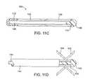
- FIGS. 11C and 11Dillustrate the deployment of deformable penetrating elements in both distal and proximal directions simultaneously.
- FIGS. 12A–12Fillustrate use of the apparatus of FIG. 1 for removing a vein from the leg of a patient according to the method of the present invention.
- a vein removal apparatus 10constructed in accordance with the principles of the present invention includes a shaft 12 having a proximal end 14 and a distal end 16 .
- the shaft 12terminates in a blunt bullet tip 18 through which a pair of penetrating elements 20 may be deployed by selectively advancing and retracting the elements relative to the apparatus.
- advancing the penetrating elements 20causes them both to move forwardly or distally relative to the device and to simultaneously move radially outwardly.
- the penetrating elements 20are shown in their deployed configurations in FIGS. 1 and 2 .
- a pushrod (or pushtube) 22is disposed within a central lumen or passage of the shaft 12 and is connected at its distal end to the proximal ends of the penetrating elements 20 .
- a proximal end of the shaft 22is connected to a sliding block 26 which is received in a central passage 28 of handle 30 .
- a thumb slide 32is connected to the sliding block 26 and is received in a slot 34 formed in the handle 30 . In this way, a user may selectively advance and retract the penetrating elements 20 by manually advancing and retracting the thumb slide 32 .
- the handle 30further includes an end plug 40 which closes its proximal end.
- a pushrod or pushtube 22can be obviated by extending proximal ends of the penetrating elements 42 and 44 rearwardly so that they are received directly in the sliding block 26 .
- Other mechanical variationsmay also be employed.
- an O-ringmay be situated in the shaft passage about the pushrod 22 in order to isolate the handle from blood and other contamination.
- the shaft 12may be rigid, semi-rigid, or flexible.
- Rigid structuresmay be formed from stainless steel.
- Semi-rigid and flexible structuresmay be formed from shape memory alloys, such as nickel-titanium alloy, reinforced polymeric materials, close wound coils, or may be formed as gooseneck or other conventional shapeable shaft structures.
- shape memory alloyssuch as nickel-titanium alloy, reinforced polymeric materials, close wound coils, or may be formed as gooseneck or other conventional shapeable shaft structures.
- the length and width (usually diameter) of the shaftwill be selected to accommodate the target vein segment to be removed. Exemplary lengths and widths are set forth above.
- the bullet tip 18is attached to the distal end of the shaft 12 by conventional techniques and will usually include at least one passage therethrough for deployment of at least one penetrating element. As illustrated in FIGS. 1 and 2 , the bullet 18 includes a pair of diverging passages 42 and 44 which outwardly deflect the penetrating elements 20 , as illustrated. A greater or lesser number passages may be provided, depending on the number of penetrating elements utilized.
- bullet tip 18 ′has a pair of open channel deployment passages 42 ′ and 44 ′ which cause penetrating elements 20 to deploy radially outwardly and forwardly of the distal end of the bullet 18 ′ as shown in FIG. 3B .
- bullet tips 18 ′′have closed channel deployment passages 42 ′′ and 44 ′′ which direct the penetrating elements 20 at a sharper angle away from the emergent point within the tip.
- FIG. 3Cillustrates yet another embodiment where a triangular ramp 45 defines diverging surfaces 47 and 48 in bullet tip 49 .
- the bullet tips 18 and 49are attached to the open distal end of shaft 12 by securing a projection 43 , as illustrated in FIG. 3C .
- the penetrating elements 20may have a wide variety of configurations and be composed of a wide variety of materials.
- penetrating elements 20 ahave a circular cross-section and are received in U-shaped passages 42 a and 44 a in bullet tip 18 a. While penetrating elements having circular cross-sections will be the most common, penetrating elements 20 b having square cross-sections are illustrated in FIG. 5B . Exemplary dimensions have been described above. Channels 42 b and 44 b are shown to have rectangular cross-sections, restricting torsion of the penetrating elements 20 b.
- torsioncan limit lateral deflection of the penetrating elements 20 b, if desired.
- circular penetrating elements 20 care received in rectangular deployment channels 42 c and 44 c. Such an arrangement is advantageous in that it reduces friction during deployment.
- a wide variety of other combinations and cross-sections, both matched and mismatched,may be employed within the scope of the present invention.
- the penetrating elements 20will be inclined at a distally forward angle in the range from 5° to 80°, usually from 5° to 60°.
- Penetrating elementswill typically be composed of stainless steel, but could also be composed of shape memory alloys, such as a nickel titanium alloy, as well as resilient plastics.
- penetrating elementswill be resilient so that they spring outwardly as they are advanced from the apparatus.
- the penetrating elementscould be formed from a malleable metal which is deformed to bend at a desired angle as it extends outwardly from the vein removal apparatus.
- a pair of reciprocatable penetrating elements 20 dare mounted in a bullet tip 18 d so that they emerge in a proximal direction and can be penetrated into tissues by drawing the associated device in a proximal direction.
- fewer or more than two penetrating elementscan be provided.
- four penetrating elements 20 eare reciprocatably mounted in a bullet tip 18 e.
- Other embodiments having only a single penetrating element and/or having five or more penetrating elementswill also be within the scope of the present invention.
- a pair of penetrating elements 20 fare reciprocatably mounted in a bullet tip 18 f.
- the penetrating elements 20 fare however resilient and possess a natural shape of an everting curve.
- penetrating elements 20 fare extended radially from the bullet tip 18 f, they first emerge in a generally distal direction. As they are further advanced, the sharpened tips turn rearwardly so that they reach the fully everted configuration shown in FIG. 8 .
- a helical penetrating element 20 gcan be advanced distally from the distal end of a distal tip 20 g.
- sharpened tip 21 g of the helical penetrating element 20 gcan be cause to capture tissue.
- the penetrating element 20 gcan then be withdrawn back into distal tip 20 g to invaginate the vessel wall and facilitate removal.
- bullet tip 18can be provided with a signal generating element 50 , typically a visible or infrared light source.
- the signal generating elementis useful for assisting in placement of the device, as described in more detail below.
- penetrating elements 20 ican be provided as spiral structures wrapped around a rotatable deployment rod 22 i in bullet tip 18 i.
- penetrating element 20By rotating the deployment rod 22 i counterclockwise, (as observed in FIGS. 11A ), penetrating element 20 will be withdrawn into the interior of the bullet tip 18 i.
- deployment rod 22 iBy rotating deployment rod 22 i in a clockwise direction, the penetrating element 20 i will be advanced radially outwardly from the bullet tip 18 i, as shown in FIG. 11B .
- spiral penetrating elementscould be arranged to deploy by rotation in a counter-clockwise direction as well.
- FIGS. 12A–12Fremoval of a varicose vein according to the method of the present invention will be described.
- a proximal end of a veinis exposed by a conventional surgical technique, such as a small incision, a small venotomy, vein exteriorization, or by another conventional percutaneous approach.
- the vein removal apparatus 10is endoluminally introduced to the lumen (L) of the varicose vein (VV) to be removed, as shown in FIG. 12B .
- the light or other signal generating element 50is used to correctly position the distal end of the device at the appropriate location.
- the deviceshave employed resilient penetrating elements formed from a material having a good spring memory, such as spring stainless steel or a nickel-titanium alloy. It will also be possible to fabricate penetrating elements from a deformable or malleable material. Such deformable penetrating elements will be deflected and deformed as they are advanced over a ramp or other surface which changes their direction of travel.
- a device 100comprises a first set of distally disposed penetrating elements 102 and a second set of proximally disposed penetrating elements 104 .
- the elements 102 and 104are usually deformable or malleable so that they may be deflected in situ by advancement relative to a cam surface, as described below.
- the elements 102 and 104are mounted on a shaft 106 having an atraumatic tip 108 at its distal end.
- the tip 108has a proximal surface 110 which engages the distal ends of the second set of penetrating elements 104 .
- the elements 102 and 104interdigitate so that they can pass by each other as the first set of elements 102 is advanced distally by a pusher-tube 112 .
- each set of elementsdefines a cam surface (not shown) so that both sets will be deflected radially outwardly as the first set of elements 102 is advanced distally, as shown in FIG. 11D .
- the penetrating elements 20will be deployed radially outwardly to engage the inner surface of the vessel wall (VW).
- imaging techniquessuch as fluoroscopy or duplex ultrasound.
- the apparatus 10is rotated about its axis, as indicated by arrow 72 in FIG. 12D .
- Such rotationpulls the vessel wall radially inwardly and away from the surrounding connective tissue.
- capture and rotation of the veinwill be sufficient to both tear the vein from the surrounding connective tissue and separate the vein from the remaining portions of the vein which are not being removed.
- it might be desirable to perform a separate step of severing the venous walleither via a percutaneous approach or using an endoluminal tool (not illustrated) which could use a blade or other severing device in order to perform the desired step. It is a particular benefit of the present invention, however, that such separate severing step is usually not needed.
- the vesselcould be removed by continued rotation of the apparatus to draw down additional vessel wall, typically at least one-half of the length of the target segment to be removed, and optionally additional length up to and including the entire length of the vessel wall to be removed.
- additional vessel walltypically at least one-half of the length of the target segment to be removed, and optionally additional length up to and including the entire length of the vessel wall to be removed.
- the vesselwill break at a point intermediate within the length to be removed.
- the broken segment or lengthmay then be withdrawn and the device reintroduced to the vessel in order to capture a distal end of the remaining length and withdraw the remaining length and withdraw the remaining length (or a portion or segment thereof) from the lumen.
- the steps of introducing the apparatus, capturing a distal end of the vessel, and removing the vesselmay be repeated as many times as necessary in order to remove the entire target length of the vessel.
- the veinprior to removal of the vein, it may be desirable to disrupt the attachment of the vein to surrounding connective tissue, either by mechanical dissection techniques and/or through the use of tumescent anesthesia fluid infiltration.
- the apparatus 10may be drawn proximally, as shown by arrow 74 in FIG. 12E . Drawing the apparatus 10 in this direction pulls the vessel wall (VW) proximally, avulsing and everting the wall as it is pulled away and separated from the surrounding connecting tissue, as shown in FIG. 12E .
- the apparatus 10may be continuously or periodically rotated about its axis as it is being drawn proximately. Such further rotation can facilitate vein avulsion, making it less traumatic for the patient. The rotation also maintains the torsional load on the devise and penetrating elements so that vessel engagement is maintained.
- the vesselcan be severed and the remaining end closed by conventional surgical techniques or simply allowed to heal without further intervention.
- the vessel wallwill have been completely withdrawn from the surrounding connective tissue, as shown in FIG. 12F .
- the procedurecan be repeated for additional lengths of the same varicose vein or for different varicose veins, as desired.
Landscapes
- Health & Medical Sciences (AREA)
- Surgery (AREA)
- Life Sciences & Earth Sciences (AREA)
- Biomedical Technology (AREA)
- Nuclear Medicine, Radiotherapy & Molecular Imaging (AREA)
- Engineering & Computer Science (AREA)
- Rheumatology (AREA)
- Heart & Thoracic Surgery (AREA)
- Medical Informatics (AREA)
- Molecular Biology (AREA)
- Animal Behavior & Ethology (AREA)
- General Health & Medical Sciences (AREA)
- Public Health (AREA)
- Veterinary Medicine (AREA)
- Surgical Instruments (AREA)
Abstract
Description
Claims (11)
Priority Applications (1)
| Application Number | Priority Date | Filing Date | Title |
|---|---|---|---|
| US10/309,940US7163546B2 (en) | 2001-12-21 | 2002-12-03 | Method and apparatus for avulsion of varicose veins |
Applications Claiming Priority (2)
| Application Number | Priority Date | Filing Date | Title |
|---|---|---|---|
| US34271901P | 2001-12-21 | 2001-12-21 | |
| US10/309,940US7163546B2 (en) | 2001-12-21 | 2002-12-03 | Method and apparatus for avulsion of varicose veins |
Publications (2)
| Publication Number | Publication Date |
|---|---|
| US20030125759A1 US20030125759A1 (en) | 2003-07-03 |
| US7163546B2true US7163546B2 (en) | 2007-01-16 |
Family
ID=26977112
Family Applications (1)
| Application Number | Title | Priority Date | Filing Date |
|---|---|---|---|
| US10/309,940Expired - Fee RelatedUS7163546B2 (en) | 2001-12-21 | 2002-12-03 | Method and apparatus for avulsion of varicose veins |
Country Status (1)
| Country | Link |
|---|---|
| US (1) | US7163546B2 (en) |
Cited By (18)
| Publication number | Priority date | Publication date | Assignee | Title |
|---|---|---|---|---|
| US20100280328A1 (en)* | 2009-05-01 | 2010-11-04 | Tyco Healthcare Group, Lp | Methods and systems for illumination during phlebectomy procedures |
| US20110124958A1 (en)* | 2009-11-23 | 2011-05-26 | Nelson Dvora Y | Device and method for extracting tubular structures |
| US20110264128A1 (en)* | 2010-04-27 | 2011-10-27 | Medtronic Vascular, Inc. | Percutaneous Methods for Apparatus for Creating Native Tissue Venous Valves |
| US20110320674A1 (en)* | 2010-06-23 | 2011-12-29 | International Business Machines Corporation | Upbound input/output expansion request and response processing in a pcie architecture |
| US8416834B2 (en) | 2010-06-23 | 2013-04-09 | International Business Machines Corporation | Spread spectrum wireless communication code for data center environments |
| US8417911B2 (en) | 2010-06-23 | 2013-04-09 | International Business Machines Corporation | Associating input/output device requests with memory associated with a logical partition |
| US8615622B2 (en) | 2010-06-23 | 2013-12-24 | International Business Machines Corporation | Non-standard I/O adapters in a standardized I/O architecture |
| US8615586B2 (en) | 2010-06-23 | 2013-12-24 | International Business Machines Corporation | Discovery of logical images at storage area network endpoints |
| US8645767B2 (en) | 2010-06-23 | 2014-02-04 | International Business Machines Corporation | Scalable I/O adapter function level error detection, isolation, and reporting |
| US8656228B2 (en) | 2010-06-23 | 2014-02-18 | International Business Machines Corporation | Memory error isolation and recovery in a multiprocessor computer system |
| US20140052234A1 (en)* | 2011-04-18 | 2014-02-20 | Vascular Graft Solutions Ltd. | Devices and methods for deploying implantable sleeves over blood vessels |
| US8671287B2 (en) | 2010-06-23 | 2014-03-11 | International Business Machines Corporation | Redundant power supply configuration for a data center |
| US8677180B2 (en) | 2010-06-23 | 2014-03-18 | International Business Machines Corporation | Switch failover control in a multiprocessor computer system |
| US8745292B2 (en) | 2010-06-23 | 2014-06-03 | International Business Machines Corporation | System and method for routing I/O expansion requests and responses in a PCIE architecture |
| US8918573B2 (en) | 2010-06-23 | 2014-12-23 | International Business Machines Corporation | Input/output (I/O) expansion response processing in a peripheral component interconnect express (PCIe) environment |
| US20160310161A1 (en)* | 2013-03-15 | 2016-10-27 | Kyphon Sarl | Retractable device to dissect and evacuate ligamentum flavum in lumber spinal stenosis |
| US9782191B2 (en) | 2014-01-21 | 2017-10-10 | Cook Medical Technologies Llc | Cutting devices and methods |
| US11877784B2 (en) | 2014-03-26 | 2024-01-23 | Venclose, Inc. | Venous disease treatment |
Families Citing this family (17)
| Publication number | Priority date | Publication date | Assignee | Title |
|---|---|---|---|---|
| US7789876B2 (en)* | 2000-08-14 | 2010-09-07 | Tyco Healthcare Group, Lp | Method and apparatus for positioning a catheter relative to an anatomical junction |
| US7717930B2 (en)* | 2004-02-27 | 2010-05-18 | Cook Incorporated | Valvulotome with a cutting edge |
| US8398663B2 (en)* | 2004-02-27 | 2013-03-19 | Cook Medical Technologies Llc | Valvulotome device and method |
| RU2283624C2 (en)* | 2004-03-09 | 2006-09-20 | Военно-медицинский институт Федеральной службы безопасности Российской Федерации (ВМИ ФСБ России) | Method and device for through-skin phleboectomy |
| IL161928A (en)* | 2004-05-11 | 2005-11-20 | Pikus Valery | Instrument and method for cosmetic removal of superficial varicose veins |
| US20070244371A1 (en)* | 2006-04-04 | 2007-10-18 | Nguyen Hoa D | Phlebectomy illumination device and methods |
| WO2008093337A2 (en)* | 2007-02-01 | 2008-08-07 | Simedeq Medical Equipment Ltd. | Varicose vein removal device |
| IE20090430A1 (en)* | 2008-05-29 | 2010-03-03 | Embricon Ltd | A vein stripping device device |
| CN102112063A (en)* | 2008-06-06 | 2011-06-29 | 瓦里克斯医疗公司 | Vein therapy device and method |
| US20100198209A1 (en)* | 2009-01-30 | 2010-08-05 | Tartaglia Joseph M | Hemorrhoid Therapy and Method |
| US8579922B2 (en)* | 2009-10-05 | 2013-11-12 | Covidien Lp | Method of suture identification and mesh marking for orienting and locating a mesh during hernia repair |
| US8834500B2 (en)* | 2011-03-04 | 2014-09-16 | Vascular Solutions, Inc. | Hand-held vein removal device |
| US20130041266A1 (en)* | 2011-08-12 | 2013-02-14 | Tyco Healthcare Group Lp, | System and Method for Indicating Positioning of an Internal Anatomical Feature |
| US8971989B2 (en) | 2012-01-24 | 2015-03-03 | Covidien Lp | Magnetic field device for mapping and navigation in laparoscopic surgery |
| WO2013168498A1 (en)* | 2012-05-10 | 2013-11-14 | オリンパスメディカルシステムズ株式会社 | Treatment tool for endoscope |
| CN107582110B (en)* | 2017-10-20 | 2023-09-22 | 上海普益医疗器械股份有限公司 | Varicose vein stripping booster |
| WO2020222808A1 (en)* | 2019-04-30 | 2020-11-05 | C.R. Bard, Inc. | Endovascular cutting catheter and related method |
Citations (22)
| Publication number | Priority date | Publication date | Assignee | Title |
|---|---|---|---|---|
| US3508553A (en) | 1968-03-06 | 1970-04-28 | Maurice S Kanbar | Surgical vein stripping instrument for phlebectomies |
| US3568677A (en) | 1968-11-19 | 1971-03-09 | Brymill Corp | Surgical vein stripper |
| US3764437A (en) | 1970-08-14 | 1973-10-09 | Opti Holding Ag | Method of making waterproof slide fastener stringer |
| US3764427A (en) | 1970-02-19 | 1973-10-09 | Codman & Shurtleff | Vein stripping instrument |
| US4517965A (en) | 1983-06-27 | 1985-05-21 | Ellison Arthur E | Tissue retractor |
| US5011489A (en) | 1989-10-05 | 1991-04-30 | University Of South Florida | Endothelium stripper and method of using the same |
| WO1994021177A1 (en) | 1993-03-16 | 1994-09-29 | Astra Aktiebolag | Device for the extirpation of varicose veins |
| US5792168A (en) | 1996-11-14 | 1998-08-11 | Suval; William D. | Apparatus for treating varicose veins |
| US5843104A (en)* | 1995-11-21 | 1998-12-01 | Samuels; Peter B. | Method of removing blood vessels from the human body |
| US5893858A (en) | 1997-10-06 | 1999-04-13 | Smith & Nephew, Inc. | Method for removing veins |
| US6019771A (en)* | 1996-12-02 | 2000-02-01 | Cardiothoracic Systems, Inc. | Devices and methods for minimally invasive harvesting of a vessel especially the saphenous vein for coronary bypass grafting |
| US6030200A (en) | 1994-08-05 | 2000-02-29 | Fanuc Ltd. | Electric injection molding machine |
| US6042538A (en)* | 1998-11-18 | 2000-03-28 | Emory University | Device for endoscopic vessel harvesting |
| US6071292A (en)* | 1997-06-28 | 2000-06-06 | Transvascular, Inc. | Transluminal methods and devices for closing, forming attachments to, and/or forming anastomotic junctions in, luminal anatomical structures |
| US6077289A (en) | 1995-05-19 | 2000-06-20 | General Surgical Innovations | Methods and devices for harvesting blood vessels with balloons |
| US6077261A (en)* | 1995-06-07 | 2000-06-20 | Radiotherapeutics Corporation | Device for permanent vessel occlusion |
| WO2000042918A1 (en)* | 1999-01-19 | 2000-07-27 | Welten Robertus Johannes Theod | Device for stripping veins |
| WO2000045691A2 (en) | 1999-02-04 | 2000-08-10 | Da Silva Branco Antonio Carlos | Kit for endovascular venous surgery |
| WO2001037739A1 (en) | 1999-11-24 | 2001-05-31 | Smith & Nephew, Inc. | Methods and apparatus for removing veins |
| US20030225426A1 (en)* | 2002-04-03 | 2003-12-04 | Thomas J. Fogarty, M.D. | Methods and systems for vein harvesting and fistula creation |
| US20040087367A1 (en)* | 2002-10-31 | 2004-05-06 | Hendrickson Robert J. | Real-time rules-based service management system for gaming activities |
| US6887251B1 (en)* | 2001-07-12 | 2005-05-03 | William D. Suval | Method and apparatus for vessel harvesting |
Family Cites Families (2)
| Publication number | Priority date | Publication date | Assignee | Title |
|---|---|---|---|---|
| US4517985A (en)* | 1982-06-01 | 1985-05-21 | Diasonics, Inc. | Neonate ultrasonic scanner |
| JP3474407B2 (en)* | 1997-01-17 | 2003-12-08 | 京セラミタ株式会社 | Image forming apparatus and method |
- 2002
- 2002-12-03USUS10/309,940patent/US7163546B2/ennot_activeExpired - Fee Related
Patent Citations (24)
| Publication number | Priority date | Publication date | Assignee | Title |
|---|---|---|---|---|
| US3508553A (en) | 1968-03-06 | 1970-04-28 | Maurice S Kanbar | Surgical vein stripping instrument for phlebectomies |
| US3568677A (en) | 1968-11-19 | 1971-03-09 | Brymill Corp | Surgical vein stripper |
| US3764427A (en) | 1970-02-19 | 1973-10-09 | Codman & Shurtleff | Vein stripping instrument |
| US3764437A (en) | 1970-08-14 | 1973-10-09 | Opti Holding Ag | Method of making waterproof slide fastener stringer |
| US4517965A (en) | 1983-06-27 | 1985-05-21 | Ellison Arthur E | Tissue retractor |
| US5011489A (en) | 1989-10-05 | 1991-04-30 | University Of South Florida | Endothelium stripper and method of using the same |
| WO1994021177A1 (en) | 1993-03-16 | 1994-09-29 | Astra Aktiebolag | Device for the extirpation of varicose veins |
| US6030200A (en) | 1994-08-05 | 2000-02-29 | Fanuc Ltd. | Electric injection molding machine |
| US6077289A (en) | 1995-05-19 | 2000-06-20 | General Surgical Innovations | Methods and devices for harvesting blood vessels with balloons |
| US6077261A (en)* | 1995-06-07 | 2000-06-20 | Radiotherapeutics Corporation | Device for permanent vessel occlusion |
| US5843104A (en)* | 1995-11-21 | 1998-12-01 | Samuels; Peter B. | Method of removing blood vessels from the human body |
| US5792168A (en) | 1996-11-14 | 1998-08-11 | Suval; William D. | Apparatus for treating varicose veins |
| US6019771A (en)* | 1996-12-02 | 2000-02-01 | Cardiothoracic Systems, Inc. | Devices and methods for minimally invasive harvesting of a vessel especially the saphenous vein for coronary bypass grafting |
| US6071292A (en)* | 1997-06-28 | 2000-06-06 | Transvascular, Inc. | Transluminal methods and devices for closing, forming attachments to, and/or forming anastomotic junctions in, luminal anatomical structures |
| WO1999017664A1 (en) | 1997-10-06 | 1999-04-15 | Smith & Nephew, Inc. | Methods and apparatus for removing veins |
| US5893858A (en) | 1997-10-06 | 1999-04-13 | Smith & Nephew, Inc. | Method for removing veins |
| US6042538A (en)* | 1998-11-18 | 2000-03-28 | Emory University | Device for endoscopic vessel harvesting |
| WO2000042918A1 (en)* | 1999-01-19 | 2000-07-27 | Welten Robertus Johannes Theod | Device for stripping veins |
| US6652549B1 (en)* | 1999-01-19 | 2003-11-25 | Le Maitre Vascular, Inc. | Device for stripping veins |
| WO2000045691A2 (en) | 1999-02-04 | 2000-08-10 | Da Silva Branco Antonio Carlos | Kit for endovascular venous surgery |
| WO2001037739A1 (en) | 1999-11-24 | 2001-05-31 | Smith & Nephew, Inc. | Methods and apparatus for removing veins |
| US6887251B1 (en)* | 2001-07-12 | 2005-05-03 | William D. Suval | Method and apparatus for vessel harvesting |
| US20030225426A1 (en)* | 2002-04-03 | 2003-12-04 | Thomas J. Fogarty, M.D. | Methods and systems for vein harvesting and fistula creation |
| US20040087367A1 (en)* | 2002-10-31 | 2004-05-06 | Hendrickson Robert J. | Real-time rules-based service management system for gaming activities |
Non-Patent Citations (2)
| Title |
|---|
| Ricci, Stefano. et al., Ambulatory Phlebectomy: A Practical Guide for Treating Vericose Veins. Mosby-Yearbook, St. Louis, MO., (1995) pp. 67-167. |
| Weiss, Robert A., et al., Eds., Vein Diagnosis and Treatment: A Comprehensive Approach.McGraw Hill Medical Publishing Division, New York, (2001) Chapter 22, pp. 197-210. |
Cited By (31)
| Publication number | Priority date | Publication date | Assignee | Title |
|---|---|---|---|---|
| US20100280328A1 (en)* | 2009-05-01 | 2010-11-04 | Tyco Healthcare Group, Lp | Methods and systems for illumination during phlebectomy procedures |
| US20110124958A1 (en)* | 2009-11-23 | 2011-05-26 | Nelson Dvora Y | Device and method for extracting tubular structures |
| US8926642B2 (en) | 2009-11-23 | 2015-01-06 | Nelson Medical Enterprises, Llc | Method for extracting tubular structures |
| US8460323B2 (en)* | 2010-04-27 | 2013-06-11 | Medtronic Vascular, Inc. | Percutaneous methods for apparatus for creating native tissue venous valves |
| US8834499B2 (en) | 2010-04-27 | 2014-09-16 | Medtronic Vascular, Inc. | Percutaneous methods and apparatus for creating native tissue venous valves |
| US20110264128A1 (en)* | 2010-04-27 | 2011-10-27 | Medtronic Vascular, Inc. | Percutaneous Methods for Apparatus for Creating Native Tissue Venous Valves |
| US8700959B2 (en) | 2010-06-23 | 2014-04-15 | International Business Machines Corporation | Scalable I/O adapter function level error detection, isolation, and reporting |
| US8677180B2 (en) | 2010-06-23 | 2014-03-18 | International Business Machines Corporation | Switch failover control in a multiprocessor computer system |
| US8615622B2 (en) | 2010-06-23 | 2013-12-24 | International Business Machines Corporation | Non-standard I/O adapters in a standardized I/O architecture |
| US8615586B2 (en) | 2010-06-23 | 2013-12-24 | International Business Machines Corporation | Discovery of logical images at storage area network endpoints |
| US8645606B2 (en)* | 2010-06-23 | 2014-02-04 | International Business Machines Corporation | Upbound input/output expansion request and response processing in a PCIe architecture |
| US8645767B2 (en) | 2010-06-23 | 2014-02-04 | International Business Machines Corporation | Scalable I/O adapter function level error detection, isolation, and reporting |
| US8656228B2 (en) | 2010-06-23 | 2014-02-18 | International Business Machines Corporation | Memory error isolation and recovery in a multiprocessor computer system |
| US8457174B2 (en) | 2010-06-23 | 2013-06-04 | International Business Machines Corporation | Spread spectrum wireless communication code for data center environments |
| US8671287B2 (en) | 2010-06-23 | 2014-03-11 | International Business Machines Corporation | Redundant power supply configuration for a data center |
| US9298659B2 (en) | 2010-06-23 | 2016-03-29 | International Business Machines Corporation | Input/output (I/O) expansion response processing in a peripheral component interconnect express (PCIE) environment |
| US8416834B2 (en) | 2010-06-23 | 2013-04-09 | International Business Machines Corporation | Spread spectrum wireless communication code for data center environments |
| US8745292B2 (en) | 2010-06-23 | 2014-06-03 | International Business Machines Corporation | System and method for routing I/O expansion requests and responses in a PCIE architecture |
| US20110320674A1 (en)* | 2010-06-23 | 2011-12-29 | International Business Machines Corporation | Upbound input/output expansion request and response processing in a pcie architecture |
| US8918573B2 (en) | 2010-06-23 | 2014-12-23 | International Business Machines Corporation | Input/output (I/O) expansion response processing in a peripheral component interconnect express (PCIe) environment |
| US8769180B2 (en) | 2010-06-23 | 2014-07-01 | International Business Machines Corporation | Upbound input/output expansion request and response processing in a PCIe architecture |
| US8417911B2 (en) | 2010-06-23 | 2013-04-09 | International Business Machines Corporation | Associating input/output device requests with memory associated with a logical partition |
| US9201830B2 (en) | 2010-06-23 | 2015-12-01 | International Business Machines Corporation | Input/output (I/O) expansion response processing in a peripheral component interconnect express (PCIe) environment |
| US10052218B2 (en)* | 2011-04-18 | 2018-08-21 | Vascular Graft Solutions Ltd. | Devices and methods for deploying implantable sleeves over blood vessels |
| US20140052234A1 (en)* | 2011-04-18 | 2014-02-20 | Vascular Graft Solutions Ltd. | Devices and methods for deploying implantable sleeves over blood vessels |
| US10117665B2 (en)* | 2013-03-15 | 2018-11-06 | Medtronic Holding Company Sàrl | Retractable device to dissect and evacuate ligamentum flavum in lumbar spinal stenosis |
| US20160310161A1 (en)* | 2013-03-15 | 2016-10-27 | Kyphon Sarl | Retractable device to dissect and evacuate ligamentum flavum in lumber spinal stenosis |
| US9782191B2 (en) | 2014-01-21 | 2017-10-10 | Cook Medical Technologies Llc | Cutting devices and methods |
| US10918408B2 (en) | 2014-01-21 | 2021-02-16 | Cook Medical Technologies Llc | Cutting devices and methods |
| US11877784B2 (en) | 2014-03-26 | 2024-01-23 | Venclose, Inc. | Venous disease treatment |
| US12396778B2 (en) | 2014-03-26 | 2025-08-26 | Venclose, Inc. | Venous disease treatment |
Also Published As
| Publication number | Publication date |
|---|---|
| US20030125759A1 (en) | 2003-07-03 |
Similar Documents
| Publication | Publication Date | Title |
|---|---|---|
| US7163546B2 (en) | Method and apparatus for avulsion of varicose veins | |
| CN111343932B (en) | Flip thrombectomy device with enhanced tracking | |
| US5906620A (en) | Surgical cauterization snare with ligating suture | |
| US10779810B2 (en) | Devices and methods for surgical retraction | |
| US8475476B2 (en) | System and method for accessing a body cavity | |
| US7455675B2 (en) | Device and method for withdrawing a tubular body part | |
| JP4776881B2 (en) | Device for endoscopic suturing | |
| US10433850B2 (en) | Endoscopic ligation | |
| EP0831744B1 (en) | Devices for blood vessel harvesting | |
| US8092472B2 (en) | Methods and devices for endoscopic treatment of organs | |
| EP1435849B1 (en) | Apparatus for deploying a clip to compress body tissue | |
| EP2083702B1 (en) | Axial stitching device | |
| US20210145442A1 (en) | Systems and methods to effect movement of tissue structures | |
| US20080015613A1 (en) | System and method for endoscopic treatment of tissue | |
| JP2004531327A (en) | Conduit collection instrument and method | |
| WO1997028745A1 (en) | Surgical clips and methods for tissue approximation | |
| WO2009154192A1 (en) | Lumenal wall puncturing overtube | |
| JP2012500098A (en) | Instrument for excision of lymph nodes or attachment to tissue during transluminal procedures | |
| US20200046217A1 (en) | Systems, devices, and related methods for retracting tissue | |
| WO2003013367A2 (en) | Vascular harvesting tool and methods | |
| US20220000501A1 (en) | Passing tension member around tissue mass | |
| US10363087B2 (en) | Tissue resection device | |
| US12150643B2 (en) | Endoscopic treatment device | |
| US20220346797A1 (en) | Device and method for passing tension member around tissue mass | |
| US11419610B2 (en) | Device and method for passing tension member around tissue mass |
Legal Events
| Date | Code | Title | Description |
|---|---|---|---|
| AS | Assignment | Owner name:VNUS MEDICAL TECHNOLOGIES, INC., CALIFORNIA Free format text:ASSIGNMENT OF ASSIGNORS INTEREST;ASSIGNORS:MIRIZZI, MICHAEL S.;PARKER, MARK P.;TANTISIRA, RADIT;AND OTHERS;REEL/FRAME:013556/0908;SIGNING DATES FROM 20021122 TO 20021126 | |
| FEPP | Fee payment procedure | Free format text:PAT HOLDER NO LONGER CLAIMS SMALL ENTITY STATUS, ENTITY STATUS SET TO UNDISCOUNTED (ORIGINAL EVENT CODE: STOL); ENTITY STATUS OF PATENT OWNER: LARGE ENTITY | |
| AS | Assignment | Owner name:VNUS MEDICAL TECHNOLOGIES, LLC, MASSACHUSETTS Free format text:CHANGE OF NAME;ASSIGNOR:VNUS MEDICAL TECHNOLOGIES, INC.;REEL/FRAME:023379/0892 Effective date:20090626 Owner name:TYCO HEALTHCARE GROUP, LP, MASSACHUSETTS Free format text:ASSIGNMENT OF ASSIGNORS INTEREST;ASSIGNOR:VNUS MEDICAL TECHNOLOGIES, LLC;REEL/FRAME:023379/0901 Effective date:20090626 Owner name:VNUS MEDICAL TECHNOLOGIES, LLC,MASSACHUSETTS Free format text:CHANGE OF NAME;ASSIGNOR:VNUS MEDICAL TECHNOLOGIES, INC.;REEL/FRAME:023379/0892 Effective date:20090626 Owner name:TYCO HEALTHCARE GROUP, LP,MASSACHUSETTS Free format text:ASSIGNMENT OF ASSIGNORS INTEREST;ASSIGNOR:VNUS MEDICAL TECHNOLOGIES, LLC;REEL/FRAME:023379/0901 Effective date:20090626 | |
| FEPP | Fee payment procedure | Free format text:PAYOR NUMBER ASSIGNED (ORIGINAL EVENT CODE: ASPN); ENTITY STATUS OF PATENT OWNER: LARGE ENTITY | |
| AS | Assignment | Owner name:VNUS MEDICAL TECHNOLOGIES, LLC,MASSACHUSETTS Free format text:CHANGE OF NAME;ASSIGNOR:VNUS MEDICAL TECHNOLOGIES, INC.;REEL/FRAME:023928/0932 Effective date:20090626 Owner name:TYCO HEALTHCARE GROUP, LP,MASSACHUSETTS Free format text:ASSIGNMENT OF ASSIGNORS INTEREST;ASSIGNOR:VNUS MEDICAL TECHNOLOGIES, LLC;REEL/FRAME:023928/0943 Effective date:20090626 Owner name:VNUS MEDICAL TECHNOLOGIES, LLC, MASSACHUSETTS Free format text:CHANGE OF NAME;ASSIGNOR:VNUS MEDICAL TECHNOLOGIES, INC.;REEL/FRAME:023928/0932 Effective date:20090626 Owner name:TYCO HEALTHCARE GROUP, LP, MASSACHUSETTS Free format text:ASSIGNMENT OF ASSIGNORS INTEREST;ASSIGNOR:VNUS MEDICAL TECHNOLOGIES, LLC;REEL/FRAME:023928/0943 Effective date:20090626 | |
| FPAY | Fee payment | Year of fee payment:4 | |
| AS | Assignment | Owner name:COVIDIEN LP, MASSACHUSETTS Free format text:CHANGE OF NAME;ASSIGNOR:TYCO HEALTHCARE GROUP LP;REEL/FRAME:029595/0101 Effective date:20120928 | |
| REMI | Maintenance fee reminder mailed | ||
| LAPS | Lapse for failure to pay maintenance fees | ||
| STCH | Information on status: patent discontinuation | Free format text:PATENT EXPIRED DUE TO NONPAYMENT OF MAINTENANCE FEES UNDER 37 CFR 1.362 | |
| FP | Lapsed due to failure to pay maintenance fee | Effective date:20150116 |