US7163539B2 - Biased angle polyaxial pedicle screw assembly - Google Patents
Biased angle polyaxial pedicle screw assemblyDownload PDFInfo
- Publication number
- US7163539B2 US7163539B2US11/048,213US4821305AUS7163539B2US 7163539 B2US7163539 B2US 7163539B2US 4821305 AUS4821305 AUS 4821305AUS 7163539 B2US7163539 B2US 7163539B2
- Authority
- US
- United States
- Prior art keywords
- screw head
- screw
- fixator component
- bone fixator
- assembly
- Prior art date
- Legal status (The legal status is an assumption and is not a legal conclusion. Google has not performed a legal analysis and makes no representation as to the accuracy of the status listed.)
- Expired - Lifetime, expires
Links
Images


Classifications
- A—HUMAN NECESSITIES
- A61—MEDICAL OR VETERINARY SCIENCE; HYGIENE
- A61B—DIAGNOSIS; SURGERY; IDENTIFICATION
- A61B17/00—Surgical instruments, devices or methods
- A61B17/56—Surgical instruments or methods for treatment of bones or joints; Devices specially adapted therefor
- A61B17/58—Surgical instruments or methods for treatment of bones or joints; Devices specially adapted therefor for osteosynthesis, e.g. bone plates, screws or setting implements
- A61B17/68—Internal fixation devices, including fasteners and spinal fixators, even if a part thereof projects from the skin
- A61B17/70—Spinal positioners or stabilisers, e.g. stabilisers comprising fluid filler in an implant
- A61B17/7001—Screws or hooks combined with longitudinal elements which do not contact vertebrae
- A61B17/7035—Screws or hooks, wherein a rod-clamping part and a bone-anchoring part can pivot relative to each other
- A61B17/7038—Screws or hooks, wherein a rod-clamping part and a bone-anchoring part can pivot relative to each other to a different extent in different directions, e.g. within one plane only
- A—HUMAN NECESSITIES
- A61—MEDICAL OR VETERINARY SCIENCE; HYGIENE
- A61B—DIAGNOSIS; SURGERY; IDENTIFICATION
- A61B17/00—Surgical instruments, devices or methods
- A61B17/56—Surgical instruments or methods for treatment of bones or joints; Devices specially adapted therefor
- A61B17/58—Surgical instruments or methods for treatment of bones or joints; Devices specially adapted therefor for osteosynthesis, e.g. bone plates, screws or setting implements
- A61B17/68—Internal fixation devices, including fasteners and spinal fixators, even if a part thereof projects from the skin
- A61B17/70—Spinal positioners or stabilisers, e.g. stabilisers comprising fluid filler in an implant
- A61B17/7001—Screws or hooks combined with longitudinal elements which do not contact vertebrae
- A61B17/7035—Screws or hooks, wherein a rod-clamping part and a bone-anchoring part can pivot relative to each other
- A61B17/7037—Screws or hooks, wherein a rod-clamping part and a bone-anchoring part can pivot relative to each other wherein pivoting is blocked when the rod is clamped
- A—HUMAN NECESSITIES
- A61—MEDICAL OR VETERINARY SCIENCE; HYGIENE
- A61B—DIAGNOSIS; SURGERY; IDENTIFICATION
- A61B17/00—Surgical instruments, devices or methods
- A61B17/56—Surgical instruments or methods for treatment of bones or joints; Devices specially adapted therefor
- A61B17/58—Surgical instruments or methods for treatment of bones or joints; Devices specially adapted therefor for osteosynthesis, e.g. bone plates, screws or setting implements
- A61B17/68—Internal fixation devices, including fasteners and spinal fixators, even if a part thereof projects from the skin
- A61B17/70—Spinal positioners or stabilisers, e.g. stabilisers comprising fluid filler in an implant
- A61B17/7001—Screws or hooks combined with longitudinal elements which do not contact vertebrae
- A61B17/7032—Screws or hooks with U-shaped head or back through which longitudinal rods pass
Definitions
- the embodiments of the inventiongenerally relate to medical devices and assemblies, and more particularly to an orthopedic surgical implant assembly used in the field of surgical lumbar, thoracic, and cervical spine treatment.
- Surgical procedures treating spinal injuriesare one of the most complex and challenging surgeries for both the patient and the surgeon.
- surgeonsmay attempt to “fuse” them together by attaching screw-like devices into the pedicles of the spine and thereby connecting several vertebrae (typically two or more) using a semi-rigid rod.
- most surgeonsmust bend the rod (causing notches thereby reducing fatigue resistance) before placing them into two or more non-aligned pedicle screws that vary in height in order to properly stabilize the pedicle screw assembly within the patient's body.
- this bendingcauses notches and reduces fatigue resistance and wastes valuable surgery time before the surgeon is able to insert the rod. That is, the surgeon must sacrifice the freedom of optimal screw placement in the spine for ease of construct assembly.
- surgeonsmust pre-operatively choose between different spinal systems with differing rod sizes pre-operatively sometimes causing delays in surgery while waiting for more adequate systems to be sterilized.
- Most conventional systemsdepend on deformation and notching of the rod to be able to lock it into the screw head. This tends to significantly reduce the fatigue life of the rod.
- Some surgeonsprefer monoaxial screws for rigidity, while some sacrifice rigidity for surgical flexibility in screw placement. Therefore, a system is needed to accommodate both theories. For example, during scoliosis surgery conventional polyaxial systems typically cannot lock into a desired position to persuade the spinal column into the desired correction before final construct assembly.
- top loading polyaxial spine screwsaddress cantilever failure by utilizing too much stress to the constructs making them weaker in other areas of concern.
- most conventional polyaxial screwsdo not generally offer enough medial/lateral flexibility because the rod sits too closely on top of the center of rotation of the bone screw producing a smaller arc of rotation.
- most conventional titanium top loading screw systemsonly accommodate one rod size.
- most conventional spinal implant designscan only accommodate either a monoaxial design or, separately, a polyaxial design, but not in one assembly. As such, most conventional screw assemblies cannot accommodate 3, 3.25, 3.5, and 4 mm rod sizes in one singular screw assembly.
- the particular size of rod useddepends on the patient's size and other factors, which may not be determined until after the surgery begins and, potentially, only after the surgeon has already inserted the bone screw into the bone.
- most conventional top loading polyaxial spine screwsdo not do enough to address cantilever failure of the assembly components. Additionally, most polyaxial screws generally do not offer enough flexibility because the rod sits too closely on top of the center of rotation of the bone screw producing a smaller arc of rotation. Furthermore, most conventional top loading screw systems generally do not accommodate different rod sizes. Moreover, most conventional polyaxial screws offer an equal degree of rotation or freedom referenced to the main screw axis. However, some portions of the spine do not need the system to provide equal polyaxial motion in all directions. For example, some portions of the spine require a range of 5 degrees in one direction and 45 degrees in the opposite direction on the same plane. Generally, most conventional systems simply provide 25 degrees all around. Thus, there remains a need for a new and improved pedicle screw assembly capable of overcoming the limitations of the conventional designs thereby providing the surgeon with improved intra-operative flexibility and the patient with an improved prognosis for better and complete rehabilitation.
- an embodiment of the inventionprovides a pedicle screw assembly comprising a screw head comprising a bulbous end; a bone fixator component comprising an angled concave socket adapted to receive the bulbous end of the screw head; a pin mounted in the screw head; and a blocker adapted to engage the screw head.
- the screw headcomprises a slot adapted to receive a longitudinal member.
- the concave socket of the bone fixator componentcomprises an angled top and a rounded bottom.
- the concave socket of the bone fixator componentcomprises an inner portion adapted to receive the bulbous end of the screw head; and a dimpled outer portion.
- the pinis preferably adapted to engage the bone fixator component and the longitudinal member, and the blocker is preferably adapted to secure the longitudinal member.
- the pincomprises an upper saddle portion having a slot and a pair of upright ends; and a lower tapered portion adjacent to the slot.
- the screw headfurther comprises two opposed upright ends separated by the slot, wherein each of the opposed upright ends comprise an inner wall and an outer wall, wherein the inner wall comprises wall threads, and wherein the outer wall comprises grooves.
- the blockerpreferably comprises blocker threads configured around an outer perimeter of the blocker, the blocker threads being dimensioned and configured to mate with the wall threads.
- the bulbous end of the screw headmay comprise a plurality of slots terminating at an opening at a tip of the bulbous end.
- the bulbous end of the screw headpreferably comprises a hole configured to receive the pin.
- the bone fixator componentmay comprise any of a bone screw and a hook configuration.
- a pedicle screw assemblycomprising a longitudinal member; a screw head comprising a bulbous end, wherein the screw head has a slot adapted to receive the longitudinal member; a bone fixator component comprising a concave socket having a biased angled top and a rounded bottom adapted to receive the screw head; a locking pin adapted to engage the screw head, the bone fixator component, and the longitudinal member; and a blocker adapted to engage the screw head and to secure the longitudinal member, wherein the concave socket of the bone fixator component preferably comprises an inner portion adapted to receive the bulbous end of the screw head; and a dimpled outer portion.
- the locking pinpreferably comprises an upper saddle portion having a slot and a pair of upright ends; and a lower tapered portion adjacent to the slot.
- the bulbous end of the screw headpreferably comprises a hole configured to receive the pin.
- the bone fixator componentmay comprise any of a bone screw and a hook configuration.
- Another embodiment of the inventionprovides a method of assembling a pedicle screw assembly, wherein the method comprises attaching a screw head comprising a bulbous end to a bone fixator component, wherein the bone fixator component comprises an angled concave socket adapted to receive the bulbous end of the screw head; securing the bone fixator component in a bone; securing a locking pin in the screw head; engaging the saddle pin with the bone fixator component; inserting a longitudinal member in the screw head; and inserting a blocker in the screw head, wherein engagement of the blocker with the screw head causes expansion of the bulbous end of the screw head in the angled concave socket of the bone fixator component.
- the embodiments of the inventionoffer a surgeon more lateral corrective distance than conventional screw assemblies and can accommodate the cervical spine anatomy with a biased angle.
- the embodiments of the inventionmay be used as a fixation device in the posterior cervical-thoracic spine.
- the embodiments of the inventionprovide an improvement in the field of surgical lumbar and thoracic and cervical spine treatment.
- the assembly provided by the embodiments of the inventionmay also be used anteriorly or posteriorly.
- the assembly provided by the embodiments of the inventionmay be utilized in surgeries to achieve anterior lumbar interbody fusion, posterior lumbar interbody fusion, transverse lumbar interbody fusion, degenerative disc disease, adult and pediatric scoliosis as a fixation device, and posterior cervical fusion.
- FIG. 1illustrates an exploded view of the screw assembly according to an embodiment of the invention
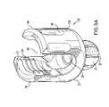
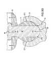
- FIG. 2(A)illustrates a perspective view of the bone fixator component of FIG. 1 according to an embodiment of the invention
- FIG. 2(B)illustrates a front view of the bone fixator component of FIG. 2(A) according to an embodiment of the invention
- FIG. 2(C)illustrates a cross-sectional top view cut along section X—X of the bone fixator component of FIG. 2(B) according to an embodiment of the invention
- FIG. 2(D)illustrates a cross-sectional side view cut along section A—A of the bone fixator component of FIG. 2(B) according to an embodiment of the invention
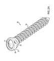
- FIG. 3(A)illustrates a perspective view of the screw head of FIG. 1 according to an embodiment of the invention
- FIG. 3(B)illustrates a front view of the screw head of FIG. 3(A) according to an embodiment of the invention
- FIG. 3(C)illustrates a bottom view of the screw head of FIG. 3(A) according to an embodiment of the invention
- FIG. 3(D)illustrates a cross-sectional side view cut along section C—C of the screw head of FIG. 3(B) according to an embodiment of the invention
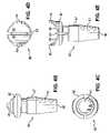
- FIG. 4(A)illustrates a perspective view of the saddle pin of FIG. 1 according to an embodiment of the invention
- FIG. 4(B)illustrates a side view of the saddle pin of FIG. 4(A) according to an embodiment of the invention
- FIG. 4(C)illustrates a bottom view of the saddle pin of FIG. 4(A) according to an embodiment of the invention
- FIG. 4(D)illustrates a top view of the saddle pin of FIG. 4(A) according to an embodiment of the invention
- FIG. 4(E)illustrates a front view of the saddle pin of FIG. 4(A) according to an embodiment of the invention
- FIG. 5(A)illustrates a perspective view of the blocker of FIG. 1 according to an embodiment of the invention
- FIG. 5(B)illustrates a cross-sectional side view of the blocker of FIG. 5(A) according to an embodiment of the invention
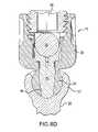
- FIGS. 6(A) through 6(D)illustrate several views of a fully engaged screw assembly according to an embodiment of the invention
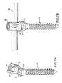
- FIGS. 7(A) through 7(B)illustrate several views of a fully engaged screw assembly in various stages of angulation according to an embodiment of the invention
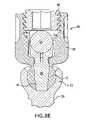
- FIGS. 8(A) through 8(E)illustrate several cross-sectional views of a screw assembly in various stages of assembly according to an embodiment of the invention
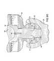
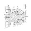
- FIGS. 9(A) through 9(D)illustrate several cross-sectional views of a screw assembly in various stages of engagement according to an embodiment of the invention.
- FIG. 10is a flow diagram illustrating a preferred method according to an embodiment of the invention.
- FIG. 1illustrates the components of the pedicle screw assembly 10 according to an embodiment of the invention.
- the assembly 10 shown in FIG. 1is for a 1-level spinal fixation construct.
- the bone screw (fixator component) 20which may be embodied as a screw, hook, or anchor, is pre-assembled at the factory by snapping the screw head 30 into the bone fixator component 20 , and then snapping the saddle pin 40 into the screw head 30 . This allows the screw head 30 to rotate about the center of rotation freely.
- This sub-assemblyis then inserted and “buried” into the spinal anatomy (not shown) as far as the level of the female dimples 24 (shown in FIG. 2(A) ) on the bone fixator component 20 .
- the bone fixator component 20is inserted in the spinal anatomy (not shown), the longitudinal member 50 , which may be embodied as a rod, bar, plate, etc., is dropped into the screw head 30 , and the blocker 60 is used to fixate the construct 10 .
- the bone fixator component 20is shown in FIGS. 2(A) through 2(D) (with reference to FIG. 1 ) with an angled cut on the top socket 23 of the implant and having a generally rounded bottom surface 26 .
- This cut topallows for the screw head 20 to angulate in one direction more than another direction to accommodate the needed extreme angles in the posterior cervical spine.
- the large angled semi-spherical socket 23 at the top of the bone fixator component 20acts as the pivot point for the screw head 30 .
- This socket 23is undercut to accommodate a snap fit in assembly and to prevent unintentional disassembly.
- the socket 23includes an inner portion 21 and an outer portion 25 , which comprises dimples (or cuts) 24 .
- the female spherical cuts 24are configured so as to be used by a screwdriver (not shown) to insert the bone fixator component 20 into the patient's spine (not shown).
- the screw head 30is shown in FIGS. 3(A) through 3(D) (with reference to FIGS. 1 through 2(D) ).
- a male spherical ball 31that is slotted 32 for assembly purposes and for expansion in the final locking of the construct 10 .
- the male spherical surface 31can be treated with a rough media to create a rough texture to encourage galling with the inner portion 21 of the large female spherical socket 23 in the bone fixator component 20 (of FIGS. 2(A) through 2(D) ).
- the screw head 30further includes a pair of opposed upright ends 34 , 35 separated by a generally U-shaped slotted section 36 adapted to receive the longitudinal member 50 .
- the inner wall 134 of the upright ends 34 , 35include threads 37 .
- the indent features 39 on the outside 135 of the screw head 30are for various instruments (not shown) to manipulate the screw head 30 during surgery.
- the saddle pin 40is illustrated in FIGS. 4(A) through 4(E) (with reference to FIGS. 1 through 3(D) ).
- the saddle pin 40desirably has a generally rounded upper portion 42 with a generally sloping upper surface 46 on top to allow the use of different size longitudinal members 50 (of FIG. 1 ) within the same assembly system 10 .
- the upper surface 46includes a slot 43 that extends down to the lower portion 47 of the saddle pin 40 to accommodate flexibility in the upper portion 42 of the saddle pin 40 .
- the tapered section 41 towards the bottom 47 of the saddle pin 40can be used to expand and “wedge” the slotted male spherical section 31 of the screw head 30 into the bone fixator component 20 (further shown in FIGS.
- the bottom tip 48 of the saddle pin 40can be rounded, flat, or pointed to “dig” in the bone fixator component 20 providing another method of locking the construct other than the wedging effect described above.
- the two small ears 44 , 45 on top of the saddle pin 40may be used to orient the saddle pin 40 to always accept a longitudinal member 50 within the screw head 30 .
- FIGS. 5(A) and 5(B)illustrate the blocker 60 , which is used to push down on the longitudinal member 50 (of FIG. 1 ) that pushes down onto the saddle pin 40 effectively locking the construct 10 .
- the threads 61 on the blocker 60are preferably configured around an outer cylindrical perimeter 63 of the blocker 60 , and are preferably standard flat buttress threads that are configured to mate with the threads 37 of the screw head 30 .
- the thread angle, ⁇equals 45° and ( ⁇ equals 90°.
- the flat type “A” buttress threads 61 of the blocker 60helps prevent the screw head 30 from splaying during final tightening (best seen in FIGS. 8(A) through 8(E) ).
- the blocker 60includes an appropriately sized hex aperture 62 for torque application.
- FIGS. 6(A) through 7(B)The various angulations scenarios of the fully-assembled screw assembly 10 are shown in FIGS. 6(A) through 7(B) .
- the medial angulation shown in FIGS. 6(A) and 6(B)show an unequal angulation.
- the medial angulation of the screw head 30 shown in FIG. 7(A)is equal to the medial angulation of the screw head 30 shown in FIG. 7(B) .
- FIGS. 6(C) and 6(D)illustrate various applications of the screw assembly 10 provided by the embodiments of the invention. As shown, the screw assembly 10 is configured to have flexibility in its design (i.e., angulation).
- FIGS. 8(A) through 8(E)illustrate cross-sectional views of the assembly 10 .
- the saddle pin 40cannot escape, fall out or vibrate out of position, and is always oriented to accept a longitudinal member 50 . It is shown in FIG. 8(A) that the taper 41 towards the bottom of the saddle pin 40 is not engaging the corresponding taper on the screw head 30 , thus allowing the screw head 30 to move freely. As shown in FIG. 8(B) , the longitudinal member 50 is then dropped into the screw head 30 and rests on the saddle pin 40 . At this point the saddle pin 40 is ready to deform to accept a larger size longitudinal member 50 than the slot 43 on top of the saddle pin 40 seems to accommodate.
- FIG. 8(C)the blocker 60 is inserted into the screw head 30 preventing the longitudinal member 50 from escaping.
- the blocker 60is now ready to apply downward forces on the saddle pin 40 through the longitudinal member 50 .
- FIG. 8(D)the blocker 60 is fully tightened to a predetermined torque.
- the saddle pin 40is driven into the bone fixator component 20 while expanding the bulbous end 31 of the screw head 30 .
- the bulbous end 31 of the screw head 30has very little room to expand. The wedging effect starts to lock the construct 10 .
- FIG. 8(E)illustrates the assembly 10 in the locked position, whereby the saddle pin 40 has penetrated the bone fixator component 20 and “lifted” the male spherical portion 31 of the screw head 30 wedging it further into the socket 23 of the bone fixator component 20 .
- FIGS. 9(A) through 9(D)illustrate various sectional views of the assembly 10 and the corresponding forces acting upon the various components of the assembly 10 during the assembling process.
- the assembly 10locks because of the engagement between the socket 23 of the bone fixator component 20 and the bulbous end 31 of screw head 30 from the force transmitted by the saddle pin 40 through the blocker 60 and the longitudinal member 50 .
- the engaging systemgenerally includes three stages: (1) before engaging (FIG. 9 (A)); (2) start to engage (FIG. 9 (B)); (3) fully engaged ( FIGS. 9(C) and 9(D) ).
- the performance of each component(bone fixator component 20 , screw head 30 , and saddle pin 50 ) varies per stage. As shown in FIG.
- the saddle pin 40has yet to transmit forces to the screw head 30 or to the bone fixator component 20 .
- the saddle pin 40sits in region R (denoted by the elliptical circles). In this stage, the saddle pin 40 has one direction of limited freedom, vertical.
- the saddle pin 40starts to engage the bone screw 20 .
- Force Ais transmitted by the longitudinal member 50 and to the saddle pin 40 forcing the area of contact to increase accordingly.
- Enough contact forceis generated to bend (denoted by force B) the male sphere 31 of the screw head 30 .
- the saddle pin 40begins to contact the female socket 23 of the bone fixator component 20 .
- FIG. 9(C)the saddle pin 40 is fully engaged.
- the blocker 60pushes downward against the longitudinal member 50 and the saddle pin 40 and creates a force A. Force A is then separated into three forces: C, B, and D 3 .
- FIG. 9(D)illustrates an alternative possibility of engaging the assembly 10 .
- the force Ais transmitting to the bone fixator component 20 and thereby creating the reaction forces D 3 or K, and depends on the shape of the tip 48 of the saddle pin 40 .
- forces D 3 or Kare pushing against the female socket 23 of the bone fixator component 20 , creating force E, and driving the screw head 30 upward.
- force EBy the screw head 30 moving upward, force D 1 is created.
- the locking mechanismis completed when forces D 1 and D 3 (or K) created a wedge between the screw head 30 and the bone fixator component 20 by working against forces E.
- FIG. 10is a flow diagram illustrating a method of assembling a pedicle screw assembly 10 , wherein the method preferably comprises attaching ( 100 ) a screw head 30 comprising a bulbous end 31 to a bone fixator component 20 , wherein the bone fixator component 20 comprises an angled concave socket 23 adapted to receive the bulbous end 31 of the screw head 30 ; securing ( 102 ) the bone fixator component 20 in a bone; securing ( 104 ) a locking pin 40 in the screw head 30 ; engaging ( 106 ) the saddle pin 40 with the bone fixator component 20 ; inserting ( 108 ) a longitudinal member 50 in the screw head 30 ; and inserting ( 110 ) a blocker 60 in the screw head 30 , wherein engagement of the blocker 60 with the screw head 30 causes expansion of the bulbous end 31 of the screw head 30 in the angled concave socket 23 of the bone fixator component 20 .
- the embodiments of the inventionprovide a pedicle screw assembly 10 comprising a screw head 30 comprising a bulbous end 31 ; a bone fixator component 20 comprising an angled top concave socket 23 adapted to receive the bulbous end 31 of the screw head 30 ; a pin 40 mounted in the screw head 30 ; and a blocker 60 adapted to engage the screw head 30 .
- the screw head 30comprises a slot 36 adapted to receive a longitudinal member 50 .
- the concave socket 23 of the bone fixator component 20comprises a rounded bottom 26 .
- the concave socket 23 of the bone fixator component 20comprises an inner portion 21 adapted to receive the bulbous end 31 of the screw head 30 ; and a dimpled 24 outer portion 25 .
- the pin 40is preferably adapted to engage the bone fixator component 20 and the longitudinal member 50
- the blocker 60is preferably adapted to secure the longitudinal member 50
- the pin 40comprises an upper saddle portion 42 having a slot 43 and a pair of upright ends 44 , 45 ; and a lower tapered portion 47 adjacent to the slot 43
- the screw head 30further comprises two opposed upright ends 34 , 35 separated by the slot 36 , wherein each of the opposed upright ends 34 , 35 comprise an inner wall 134 and an outer wall 135 , wherein the inner wall 134 comprises wall threads 37 , and wherein the outer wall 135 comprises grooves 39 .
- the blocker 60preferably comprises blocker threads 61 configured around an outer perimeter 63 of the blocker 60 , the blocker threads 61 being dimensioned and configured to mate with the wall threads 37 of the screw head 30 .
- the bulbous end 31 of the screw head 30may comprise a plurality of slots 32 terminating at an opening 138 at the tip 139 of the bulbous end 31 .
- the bulbous end 31 of the screw head 30preferably comprises a hole 38 configured to receive the pin 40 .
- the embodiments of the inventionoffer a surgeon more lateral corrective distance than conventional screw assemblies and can accommodate the cervical spine anatomy with a biased angle.
- the embodiments of the inventionmay also be used as a fixation device in the posterior cervical-thoracic spine.
- the embodiments of the inventionprovide an improvement in the field of surgical lumbar and thoracic and cervical spine treatment.
- the assembly 10 provided by the embodiments of the inventionmay also be used anteriorly or posteriorly.
- the assembly 10 provided by the embodiments of the inventionmay be utilized in surgeries to achieve anterior lumbar interbody fusion, posterior lumbar interbody fusion, transverse lumbar interbody fusion, degenerative disc disease, adult and pediatric scoliosis as a fixation device, and posterior cervical fusion.
Landscapes
- Health & Medical Sciences (AREA)
- Orthopedic Medicine & Surgery (AREA)
- Life Sciences & Earth Sciences (AREA)
- Neurology (AREA)
- Surgery (AREA)
- Heart & Thoracic Surgery (AREA)
- Engineering & Computer Science (AREA)
- Biomedical Technology (AREA)
- Nuclear Medicine, Radiotherapy & Molecular Imaging (AREA)
- Medical Informatics (AREA)
- Molecular Biology (AREA)
- Animal Behavior & Ethology (AREA)
- General Health & Medical Sciences (AREA)
- Public Health (AREA)
- Veterinary Medicine (AREA)
- Surgical Instruments (AREA)
- Forging (AREA)
- Non-Disconnectible Joints And Screw-Threaded Joints (AREA)
Abstract
Description
Claims (6)
Priority Applications (7)
| Application Number | Priority Date | Filing Date | Title |
|---|---|---|---|
| US11/048,213US7163539B2 (en) | 2004-02-27 | 2005-02-01 | Biased angle polyaxial pedicle screw assembly |
| DE602005017470TDE602005017470D1 (en) | 2004-02-27 | 2005-02-23 | POLYAXIAL STYLE SCREW ARRANGEMENT WITH PRE-TIGHTENING ANGLE |
| AT05713963TATE447374T1 (en) | 2004-02-27 | 2005-02-23 | POLYAXIAL HAND BOLT ARRANGEMENT WITH PRE-TENSION ANGLE |
| PCT/US2005/005676WO2005086649A2 (en) | 2004-02-27 | 2005-02-23 | Biased angle polyaxial pedicle screw assembly |
| EP05713963AEP1722700B1 (en) | 2004-02-27 | 2005-02-23 | Biased angle polyaxial pedicle screw assembly |
| JP2007500934AJP4498412B2 (en) | 2004-02-27 | 2005-02-23 | Multi-axis pattern joining screw assembly having deflection angle |
| US11/564,972US7763057B2 (en) | 2004-02-27 | 2006-11-30 | Biased angle polyaxial pedicle screw assembly |
Applications Claiming Priority (3)
| Application Number | Priority Date | Filing Date | Title |
|---|---|---|---|
| US54854304P | 2004-02-27 | 2004-02-27 | |
| US62245404P | 2004-10-27 | 2004-10-27 | |
| US11/048,213US7163539B2 (en) | 2004-02-27 | 2005-02-01 | Biased angle polyaxial pedicle screw assembly |
Related Child Applications (1)
| Application Number | Title | Priority Date | Filing Date |
|---|---|---|---|
| US11/564,972ContinuationUS7763057B2 (en) | 2004-02-27 | 2006-11-30 | Biased angle polyaxial pedicle screw assembly |
Publications (2)
| Publication Number | Publication Date |
|---|---|
| US20050192573A1 US20050192573A1 (en) | 2005-09-01 |
| US7163539B2true US7163539B2 (en) | 2007-01-16 |
Family
ID=34890979
Family Applications (2)
| Application Number | Title | Priority Date | Filing Date |
|---|---|---|---|
| US11/048,213Expired - LifetimeUS7163539B2 (en) | 2004-02-27 | 2005-02-01 | Biased angle polyaxial pedicle screw assembly |
| US11/564,972Active2027-05-04US7763057B2 (en) | 2004-02-27 | 2006-11-30 | Biased angle polyaxial pedicle screw assembly |
Family Applications After (1)
| Application Number | Title | Priority Date | Filing Date |
|---|---|---|---|
| US11/564,972Active2027-05-04US7763057B2 (en) | 2004-02-27 | 2006-11-30 | Biased angle polyaxial pedicle screw assembly |
Country Status (6)
| Country | Link |
|---|---|
| US (2) | US7163539B2 (en) |
| EP (1) | EP1722700B1 (en) |
| JP (1) | JP4498412B2 (en) |
| AT (1) | ATE447374T1 (en) |
| DE (1) | DE602005017470D1 (en) |
| WO (1) | WO2005086649A2 (en) |
Cited By (132)
| Publication number | Priority date | Publication date | Assignee | Title |
|---|---|---|---|---|
| US20040153077A1 (en)* | 2000-11-10 | 2004-08-05 | Lutz Biedermann | Bone screw |
| US20040236330A1 (en)* | 2003-05-22 | 2004-11-25 | Thomas Purcell | Variable angle spinal screw assembly |
| US20050080420A1 (en)* | 2003-08-20 | 2005-04-14 | Farris Robert A. | Multi-axial orthopedic device and system |
| US20060111712A1 (en)* | 2004-11-23 | 2006-05-25 | Jackson Roger P | Spinal fixation tool set and method |
| US20060200128A1 (en)* | 2003-04-04 | 2006-09-07 | Richard Mueller | Bone anchor |
| US20070225711A1 (en)* | 2006-03-22 | 2007-09-27 | Ensign Michael D | Low top bone fixation system and method for using the same |
| US20070233094A1 (en)* | 2006-03-29 | 2007-10-04 | Dennis Colleran | Dynamic motion spinal stabilization system |
| US20070270860A1 (en)* | 2005-09-30 | 2007-11-22 | Jackson Roger P | Dynamic stabilization connecting member with slitted core and outer sleeve |
| US20080015584A1 (en)* | 2002-04-18 | 2008-01-17 | Aesculap Implant Systems | Screw and rod fixation assembly and device |
| US20080077143A1 (en)* | 2006-09-25 | 2008-03-27 | Zimmer Spine, Inc. | Apparatus for connecting a longitudinal member to a bone portion |
| US20080132953A1 (en)* | 2001-09-14 | 2008-06-05 | Stryker Spine | Methods for stabilizing bone using spinal fixation devices |
| US20080140076A1 (en)* | 2005-09-30 | 2008-06-12 | Jackson Roger P | Dynamic stabilization connecting member with slitted segment and surrounding external elastomer |
| US20080147121A1 (en)* | 2006-01-27 | 2008-06-19 | Warsaw Orthopedic, Inc. | Multi-Axial Screw Assembly |
| US20080177317A1 (en)* | 2007-01-18 | 2008-07-24 | Jackson Roger P | Dynamic stabilization connecting member with cord connection |
| US20080177260A1 (en)* | 2007-01-12 | 2008-07-24 | Lanx, Inc. | Bone fastener assembly |
| US20080188898A1 (en)* | 2004-11-23 | 2008-08-07 | Jackson Roger P | Polyaxial bone screw with multi-part shank retainer and pressure insert |
| US20080234761A1 (en)* | 2003-06-18 | 2008-09-25 | Jackson Roger P | Polyaxial bone screw with shank-retainer insert capture |
| US20080269810A1 (en)* | 2007-04-12 | 2008-10-30 | Texas Scottish Rite Hospital For Children | Orthopedic Fastener for Stabilization and Fixation |
| US20080294198A1 (en)* | 2006-01-09 | 2008-11-27 | Jackson Roger P | Dynamic spinal stabilization assembly with torsion and shear control |
| US20080319482A1 (en)* | 2007-01-18 | 2008-12-25 | Jackson Roger P | Dynamic fixation assemblies with pre-tensioned cord segments |
| US20090062866A1 (en)* | 2003-06-18 | 2009-03-05 | Jackson Roger P | Polyaxial bone anchor with helical capture connection, insert and dual locking assembly |
| US20090069849A1 (en)* | 2007-09-10 | 2009-03-12 | Oh Younghoon | Dynamic screw system |
| US20090105756A1 (en)* | 2007-10-23 | 2009-04-23 | Marc Richelsoph | Spinal implant |
| US20090198273A1 (en)* | 2008-02-02 | 2009-08-06 | Texas Scottish Rite Hospital For Children | Pedicle Screw |
| US20090198279A1 (en)* | 2008-02-02 | 2009-08-06 | Texas Scottish Rite Hospital For Children | Spinal Rod Link Reducer |
| US20090221922A1 (en)* | 2008-03-03 | 2009-09-03 | Biospinex, Llc | Methods and devices for in situ tissue navigation |
| US20090275985A1 (en)* | 2007-05-01 | 2009-11-05 | Jackson Roger P | Dynamic stabilization assembly having pre-compressed spacers with differential displacements |
| US20100010542A1 (en)* | 2006-01-09 | 2010-01-14 | Jackson Roger P | Flexible spinal stbilization assembly with spacer having off-axis core member |
| US7722652B2 (en) | 2006-01-27 | 2010-05-25 | Warsaw Orthopedic, Inc. | Pivoting joints for spinal implants including designed resistance to motion and methods of use |
| US20100174319A1 (en)* | 2001-05-09 | 2010-07-08 | Jackson Roger P | Dynamic spinal stabilization assembly with elastic bumpers and locking limited travel closure mechanisms |
| US20100174322A1 (en)* | 2009-01-03 | 2010-07-08 | Custom Spine, Inc. | Biased Bumper Mechanism and Method |
| US20100198272A1 (en)* | 2007-07-20 | 2010-08-05 | Thomas Keyer | Polyaxial bone fixation element |
| US20100204735A1 (en)* | 2009-02-11 | 2010-08-12 | Gephart Matthew P | Wide Angulation Coupling Members For Bone Fixation System |
| US20100211114A1 (en)* | 2003-06-18 | 2010-08-19 | Jackson Roger P | Polyaxial bone anchor with shelf capture connection |
| US20100268281A1 (en)* | 2005-12-19 | 2010-10-21 | Abdou M Samy | Devices and methods for inter-vertebral orthopedic device placement |
| US7833252B2 (en) | 2006-01-27 | 2010-11-16 | Warsaw Orthopedic, Inc. | Pivoting joints for spinal implants including designed resistance to motion and methods of use |
| US20100312287A1 (en)* | 2004-02-27 | 2010-12-09 | Jackson Roger P | Dynamic fixation assemblies with inner core and outer coil-like member |
| US20100318136A1 (en)* | 2003-06-18 | 2010-12-16 | Jackson Roger P | Polyaxial bone screw assembly |
| US20100331887A1 (en)* | 2006-01-09 | 2010-12-30 | Jackson Roger P | Longitudinal connecting member with sleeved tensioned cords |
| US20110015677A1 (en)* | 2004-03-03 | 2011-01-20 | Biedermann Motech Gmbh | Anchoring element and stabilization device for the dynamic stabilization of vertebrae or bones using such anchoring elements |
| US20110034258A1 (en)* | 2004-02-27 | 2011-02-10 | Custom Spine, Inc | Polyaxial Pedicle Screw Assembly and Method |
| US20110098755A1 (en)* | 2009-06-15 | 2011-04-28 | Jackson Roger P | Polyaxial bone anchor with non-pivotable retainer and pop-on shank, some with friction fit |
| US20110106166A1 (en)* | 2009-04-15 | 2011-05-05 | Tom Keyer | Revision connector for spinal constructs |
| US20110106181A1 (en)* | 2009-10-30 | 2011-05-05 | Warsaw Orthopedic, Inc. | Adjustable saddle for a bone anchor |
| US20110160779A1 (en)* | 2008-09-05 | 2011-06-30 | Synthes Usa, Llc | Bone fixation assembly |
| US20110218578A1 (en)* | 2003-06-18 | 2011-09-08 | Jackson Roger P | Polyaxial bone screw with cam connection and lock and release insert |
| WO2011053795A3 (en)* | 2009-10-30 | 2011-09-15 | Warsaw Orthopedic, Inc. | Bone engaging implant with adjustment saddle |
| US8066739B2 (en) | 2004-02-27 | 2011-11-29 | Jackson Roger P | Tool system for dynamic spinal implants |
| US8100915B2 (en) | 2004-02-27 | 2012-01-24 | Jackson Roger P | Orthopedic implant rod reduction tool set and method |
| US8137386B2 (en) | 2003-08-28 | 2012-03-20 | Jackson Roger P | Polyaxial bone screw apparatus |
| US8257398B2 (en) | 2003-06-18 | 2012-09-04 | Jackson Roger P | Polyaxial bone screw with cam capture |
| US8308782B2 (en) | 2004-11-23 | 2012-11-13 | Jackson Roger P | Bone anchors with longitudinal connecting member engaging inserts and closures for fixation and optional angulation |
| US8353932B2 (en) | 2005-09-30 | 2013-01-15 | Jackson Roger P | Polyaxial bone anchor assembly with one-piece closure, pressure insert and plastic elongate member |
| US20130018422A1 (en)* | 2011-07-11 | 2013-01-17 | Life Spine, Inc. | Spinal Rod Connector Assembly |
| US8377102B2 (en) | 2003-06-18 | 2013-02-19 | Roger P. Jackson | Polyaxial bone anchor with spline capture connection and lower pressure insert |
| US8398683B2 (en) | 2007-10-23 | 2013-03-19 | Pioneer Surgical Technology, Inc. | Rod coupling assembly and methods for bone fixation |
| US8444681B2 (en) | 2009-06-15 | 2013-05-21 | Roger P. Jackson | Polyaxial bone anchor with pop-on shank, friction fit retainer and winged insert |
| US8506601B2 (en) | 2008-10-14 | 2013-08-13 | Pioneer Surgical Technology, Inc. | Low profile dual locking fixation system and offset anchor member |
| US8591560B2 (en) | 2005-09-30 | 2013-11-26 | Roger P. Jackson | Dynamic stabilization connecting member with elastic core and outer sleeve |
| US8591515B2 (en) | 2004-11-23 | 2013-11-26 | Roger P. Jackson | Spinal fixation tool set and method |
| US8652176B2 (en)* | 2009-05-29 | 2014-02-18 | Custom Spine, Inc. | Polyaxial screw connection assembly |
| US20140114358A1 (en)* | 2010-04-05 | 2014-04-24 | David L. Brumfield | Fully-Adjustable Bone Fixation Device |
| US8734497B2 (en) | 2009-03-13 | 2014-05-27 | The University Of Toledo | Removable anchoring pedicle screw |
| US8814913B2 (en) | 2002-09-06 | 2014-08-26 | Roger P Jackson | Helical guide and advancement flange with break-off extensions |
| US8845649B2 (en) | 2004-09-24 | 2014-09-30 | Roger P. Jackson | Spinal fixation tool set and method for rod reduction and fastener insertion |
| US8911479B2 (en) | 2012-01-10 | 2014-12-16 | Roger P. Jackson | Multi-start closures for open implants |
| US8936623B2 (en) | 2003-06-18 | 2015-01-20 | Roger P. Jackson | Polyaxial bone screw assembly |
| US8979904B2 (en) | 2007-05-01 | 2015-03-17 | Roger P Jackson | Connecting member with tensioned cord, low profile rigid sleeve and spacer with torsion control |
| US8998959B2 (en) | 2009-06-15 | 2015-04-07 | Roger P Jackson | Polyaxial bone anchors with pop-on shank, fully constrained friction fit retainer and lock and release insert |
| US8998961B1 (en) | 2009-02-26 | 2015-04-07 | Lanx, Inc. | Spinal rod connector and methods |
| US9044274B2 (en) | 2010-12-01 | 2015-06-02 | Amendia, Inc. | Bone screw system |
| US9050139B2 (en) | 2004-02-27 | 2015-06-09 | Roger P. Jackson | Orthopedic implant rod reduction tool set and method |
| US9060813B1 (en) | 2008-02-29 | 2015-06-23 | Nuvasive, Inc. | Surgical fixation system and related methods |
| US9084634B1 (en) | 2010-07-09 | 2015-07-21 | Theken Spine, Llc | Uniplanar screw |
| US9168069B2 (en) | 2009-06-15 | 2015-10-27 | Roger P. Jackson | Polyaxial bone anchor with pop-on shank and winged insert with lower skirt for engaging a friction fit retainer |
| US9186184B2 (en) | 2011-02-14 | 2015-11-17 | Pioneer Surgical Technology, Inc. | Spinal fixation system and method |
| US9216041B2 (en) | 2009-06-15 | 2015-12-22 | Roger P. Jackson | Spinal connecting members with tensioned cords and rigid sleeves for engaging compression inserts |
| US9216039B2 (en) | 2004-02-27 | 2015-12-22 | Roger P. Jackson | Dynamic spinal stabilization assemblies, tool set and method |
| US9241739B2 (en) | 2008-09-12 | 2016-01-26 | DePuy Synthes Products, Inc. | Spinal stabilizing and guiding fixation system |
| US9320546B2 (en) | 2008-09-29 | 2016-04-26 | DePuy Synthes Products, Inc. | Polyaxial bottom-loading screw and rod assembly |
| US9326796B2 (en) | 2008-11-03 | 2016-05-03 | DePuy Synthes Products, Inc. | Uni-planer bone fixation assembly |
| US9345517B2 (en) | 2008-02-02 | 2016-05-24 | Globus Medical, Inc. | Pedicle screw having a removable rod coupling |
| US9387013B1 (en) | 2011-03-01 | 2016-07-12 | Nuvasive, Inc. | Posterior cervical fixation system |
| US9414863B2 (en) | 2005-02-22 | 2016-08-16 | Roger P. Jackson | Polyaxial bone screw with spherical capture, compression insert and alignment and retention structures |
| US9421041B2 (en) | 2008-09-09 | 2016-08-23 | Marc E. Richelsoph | Polyaxial screw assembly |
| US9439681B2 (en) | 2007-07-20 | 2016-09-13 | DePuy Synthes Products, Inc. | Polyaxial bone fixation element |
| US9451989B2 (en) | 2007-01-18 | 2016-09-27 | Roger P Jackson | Dynamic stabilization members with elastic and inelastic sections |
| US9480517B2 (en) | 2009-06-15 | 2016-11-01 | Roger P. Jackson | Polyaxial bone anchor with pop-on shank, shank, friction fit retainer, winged insert and low profile edge lock |
| US9504495B2 (en) | 2011-02-11 | 2016-11-29 | Blackstone Medical, Inc. | Multi-axial pedicle fixation assembly and method for use |
| US9510862B2 (en) | 2009-06-17 | 2016-12-06 | DePuy Synthes Products, Inc. | Revision connector for spinal constructs |
| US9526531B2 (en) | 2013-10-07 | 2016-12-27 | Intelligent Implant Systems, Llc | Polyaxial plate rod system and surgical procedure |
| US9579126B2 (en) | 2008-02-02 | 2017-02-28 | Globus Medical, Inc. | Spinal rod link reducer |
| US9693814B2 (en) | 2013-03-14 | 2017-07-04 | DePuy Synthes Products, Inc. | Torque limiting instrument, system and related methods |
| US9743957B2 (en) | 2004-11-10 | 2017-08-29 | Roger P. Jackson | Polyaxial bone screw with shank articulation pressure insert and method |
| USD799949S1 (en) | 2007-10-24 | 2017-10-17 | Nuvasive, Inc. | Favored angle screw |
| US9848918B2 (en) | 2005-11-21 | 2017-12-26 | DePuy Synthes Products, Inc. | Polyaxial bone anchors with increased angulation |
| US9980753B2 (en) | 2009-06-15 | 2018-05-29 | Roger P Jackson | pivotal anchor with snap-in-place insert having rotation blocking extensions |
| US10034691B1 (en) | 2015-12-03 | 2018-07-31 | Nuvasive, Inc. | Bone anchor |
| US10039578B2 (en) | 2003-12-16 | 2018-08-07 | DePuy Synthes Products, Inc. | Methods and devices for minimally invasive spinal fixation element placement |
| US10194951B2 (en) | 2005-05-10 | 2019-02-05 | Roger P. Jackson | Polyaxial bone anchor with compound articulation and pop-on shank |
| US10299839B2 (en) | 2003-12-16 | 2019-05-28 | Medos International Sárl | Percutaneous access devices and bone anchor assemblies |
| US10363070B2 (en) | 2009-06-15 | 2019-07-30 | Roger P. Jackson | Pivotal bone anchor assemblies with pressure inserts and snap on articulating retainers |
| US10383660B2 (en) | 2007-05-01 | 2019-08-20 | Roger P. Jackson | Soft stabilization assemblies with pretensioned cords |
| US10426521B2 (en)* | 2015-04-24 | 2019-10-01 | Medicrea International | Vertebral osteosynthesis equipment |
| US10485588B2 (en) | 2004-02-27 | 2019-11-26 | Nuvasive, Inc. | Spinal fixation tool attachment structure |
| US10507043B1 (en) | 2017-10-11 | 2019-12-17 | Seaspine Orthopedics Corporation | Collet for a polyaxial screw assembly |
| US10543107B2 (en) | 2009-12-07 | 2020-01-28 | Samy Abdou | Devices and methods for minimally invasive spinal stabilization and instrumentation |
| US10548740B1 (en) | 2016-10-25 | 2020-02-04 | Samy Abdou | Devices and methods for vertebral bone realignment |
| US10575961B1 (en) | 2011-09-23 | 2020-03-03 | Samy Abdou | Spinal fixation devices and methods of use |
| US10603083B1 (en) | 2010-07-09 | 2020-03-31 | Theken Spine, Llc | Apparatus and method for limiting a range of angular positions of a screw |
| US10695105B2 (en) | 2012-08-28 | 2020-06-30 | Samy Abdou | Spinal fixation devices and methods of use |
| US10857003B1 (en) | 2015-10-14 | 2020-12-08 | Samy Abdou | Devices and methods for vertebral stabilization |
| US10918498B2 (en) | 2004-11-24 | 2021-02-16 | Samy Abdou | Devices and methods for inter-vertebral orthopedic device placement |
| US10973648B1 (en) | 2016-10-25 | 2021-04-13 | Samy Abdou | Devices and methods for vertebral bone realignment |
| US11006982B2 (en) | 2012-02-22 | 2021-05-18 | Samy Abdou | Spinous process fixation devices and methods of use |
| US11173040B2 (en) | 2012-10-22 | 2021-11-16 | Cogent Spine, LLC | Devices and methods for spinal stabilization and instrumentation |
| US11179248B2 (en) | 2018-10-02 | 2021-11-23 | Samy Abdou | Devices and methods for spinal implantation |
| US11241261B2 (en) | 2005-09-30 | 2022-02-08 | Roger P Jackson | Apparatus and method for soft spinal stabilization using a tensionable cord and releasable end structure |
| US11419642B2 (en) | 2003-12-16 | 2022-08-23 | Medos International Sarl | Percutaneous access devices and bone anchor assemblies |
| US11559335B2 (en) | 2009-06-15 | 2023-01-24 | Roger P Jackson | Pivotal bone anchor assembly with insert tool deployment |
| US11751915B2 (en) | 2021-07-09 | 2023-09-12 | Roger P. Jackson | Modular spinal fixation system with bottom-loaded universal shank heads |
| US11793553B2 (en) | 2014-10-21 | 2023-10-24 | Roger P. Jackson | Pivotal bone anchor assembly having first and second split rings and an insert with post-placement tool deployment |
| US12042185B2 (en) | 2010-05-14 | 2024-07-23 | Roger P. Jackson | Pivotal bone anchor assembly with resiliently biased friction fit insert |
| US12053217B2 (en) | 2019-12-17 | 2024-08-06 | Roger P. Jackson | Receiver assembly with rotation blocking side pockets for twist-in-place insert and method of assembly |
| US12070249B2 (en) | 2014-06-04 | 2024-08-27 | Jackson Roger P | Pivotal bone anchor assembly with bottom loaded shank head engaging retainer and closure engaging insert |
| US12082853B2 (en) | 2014-10-21 | 2024-09-10 | Roger P. Jackson | Pivotal bone anchor assembly with positioner-retainer containment and insert tool deployment |
| US12102357B2 (en) | 2005-02-22 | 2024-10-01 | Roger P. Jackson | Pivotal bone anchor assembly with cannulated shank having a planar top surface and method of assembly |
| US12137945B2 (en) | 2018-09-13 | 2024-11-12 | Roger P. Jackson | Pivotal bone anchor system with modular receiver sub-assemblies and universal bone anchors |
| US12137944B2 (en) | 2018-11-16 | 2024-11-12 | Jackson Roger P | Bone anchor assembly having a tool deployable insert in compressive overlapping engagement with a retainer |
| US12357348B2 (en) | 2005-09-30 | 2025-07-15 | Roger P. Jackson | Method of assembling a pivotal bone anchor assembly with press-in-place insert |
| US12376894B2 (en) | 2005-07-14 | 2025-08-05 | Roger P. Jackson | Pivotal bone anchor assembly with ring retainer and twist-in-place pressure insert |
| US12440245B2 (en) | 2023-09-06 | 2025-10-14 | Pivotable bone anchor assembly with independent provisional locking by insert compressing member |
Families Citing this family (72)
| Publication number | Priority date | Publication date | Assignee | Title |
|---|---|---|---|---|
| US7833250B2 (en) | 2004-11-10 | 2010-11-16 | Jackson Roger P | Polyaxial bone screw with helically wound capture connection |
| US8876868B2 (en) | 2002-09-06 | 2014-11-04 | Roger P. Jackson | Helical guide and advancement flange with radially loaded lip |
| US7887539B2 (en) | 2003-01-24 | 2011-02-15 | Depuy Spine, Inc. | Spinal rod approximators |
| US7967826B2 (en)* | 2003-10-21 | 2011-06-28 | Theken Spine, Llc | Connector transfer tool for internal structure stabilization systems |
| US7588575B2 (en) | 2003-10-21 | 2009-09-15 | Innovative Spinal Technologies | Extension for use with stabilization systems for internal structures |
| US8097020B2 (en) | 2004-02-27 | 2012-01-17 | Custom Spine, Inc. | Pedicle dynamic facet arthroplasty system and method |
| US7604655B2 (en)* | 2004-10-25 | 2009-10-20 | X-Spine Systems, Inc. | Bone fixation system and method for using the same |
| WO2006047711A2 (en) | 2004-10-25 | 2006-05-04 | Alphaspine, Inc. | Pedicle screw systems and methods |
| US8926672B2 (en) | 2004-11-10 | 2015-01-06 | Roger P. Jackson | Splay control closure for open bone anchor |
| EP1830722A2 (en)* | 2004-11-19 | 2007-09-12 | Alphaspine, Inc. | Rod-coupling assemblies |
| US8403962B2 (en) | 2005-02-22 | 2013-03-26 | Roger P. Jackson | Polyaxial bone screw assembly |
| US7901437B2 (en) | 2007-01-26 | 2011-03-08 | Jackson Roger P | Dynamic stabilization member with molded connection |
| US7951172B2 (en) | 2005-03-04 | 2011-05-31 | Depuy Spine Sarl | Constrained motion bone screw assembly |
| US7951175B2 (en) | 2005-03-04 | 2011-05-31 | Depuy Spine, Inc. | Instruments and methods for manipulating a vertebra |
| ES2326123T3 (en)* | 2005-05-27 | 2009-10-01 | Biedermann Motech Gmbh | RECEPTION PART TO CONNECT A VARTAGE OF AN OSEO ANCHORAGE ELEMENT WITH A BEAR ANCHORAGE BAR AND DEVICE WITH SUCH A RECEPTION PART. |
| US7717943B2 (en) | 2005-07-29 | 2010-05-18 | X-Spine Systems, Inc. | Capless multiaxial screw and spinal fixation assembly and method |
| WO2007041702A2 (en)* | 2005-10-04 | 2007-04-12 | Alphaspine, Inc. | Pedicle screw system with provisional locking aspects |
| US7722651B2 (en)* | 2005-10-21 | 2010-05-25 | Depuy Spine, Inc. | Adjustable bone screw assembly |
| GB0521582D0 (en) | 2005-10-22 | 2005-11-30 | Depuy Int Ltd | An implant for supporting a spinal column |
| US8097025B2 (en) | 2005-10-25 | 2012-01-17 | X-Spine Systems, Inc. | Pedicle screw system configured to receive a straight or curved rod |
| GB0600662D0 (en) | 2006-01-13 | 2006-02-22 | Depuy Int Ltd | Spinal support rod kit |
| US8348952B2 (en) | 2006-01-26 | 2013-01-08 | Depuy International Ltd. | System and method for cooling a spinal correction device comprising a shape memory material for corrective spinal surgery |
| USD589147S1 (en)* | 2006-02-02 | 2009-03-24 | Innovative Spinal Technologies | Bone anchor head |
| US8029545B2 (en)* | 2006-02-07 | 2011-10-04 | Warsaw Orthopedic Inc. | Articulating connecting member and anchor systems for spinal stabilization |
| US20070233091A1 (en)* | 2006-02-23 | 2007-10-04 | Naifeh Bill R | Multi-level spherical linkage implant system |
| US7780704B2 (en)* | 2006-03-10 | 2010-08-24 | Custom Spine, Inc. | Spinal cross-connector |
| US7833248B2 (en)* | 2006-03-10 | 2010-11-16 | Custom Spine, Inc. | Spinal cross-connector |
| US20070255284A1 (en)* | 2006-04-28 | 2007-11-01 | Sdgi Holdings, Inc. | Orthopedic implant apparatus |
| US8257355B2 (en)* | 2006-06-07 | 2012-09-04 | Spinefrontier Inc. | Methods and devices for static or dynamic spine stabilization |
| US9173722B2 (en)* | 2006-10-02 | 2015-11-03 | Cendres + Metaux Sa | Anchor for securing a tooth replacement |
| US8167910B2 (en) | 2006-10-16 | 2012-05-01 | Innovative Delta Technology Llc | Bone screw and associated assembly and methods of use thereof |
| US8162990B2 (en)* | 2006-11-16 | 2012-04-24 | Spine Wave, Inc. | Multi-axial spinal fixation system |
| US9867640B2 (en) | 2006-12-07 | 2018-01-16 | Nexus Spine, LLC | Press-on pedicle screw assembly |
| US9962194B2 (en) | 2007-01-15 | 2018-05-08 | Innovative Delta Technology, Llc | Polyaxial spinal stabilizer connector and methods of use thereof |
| US7794478B2 (en) | 2007-01-15 | 2010-09-14 | Innovative Delta Technology, Llc | Polyaxial cross connector and methods of use thereof |
| US20080261174A1 (en)* | 2007-04-23 | 2008-10-23 | Gittleman Neal B | Expanding Ball Lock Oral Prosthesis Alignment Apparatus |
| US8197517B1 (en) | 2007-05-08 | 2012-06-12 | Theken Spine, Llc | Frictional polyaxial screw assembly |
| WO2008142678A2 (en)* | 2007-05-17 | 2008-11-27 | Yechiel Gotfried | Multidirectional bone fixation assembly |
| DE212007000106U1 (en)* | 2007-09-12 | 2010-07-01 | Cendres & Metaux Sa | Arrangement for forming a bridge construction and fixation screw therefor |
| GB0720762D0 (en) | 2007-10-24 | 2007-12-05 | Depuy Spine Sorl | Assembly for orthopaedic surgery |
| US8894687B2 (en) | 2011-04-25 | 2014-11-25 | Nexus Spine, L.L.C. | Coupling system for surgical construct |
| US8709015B2 (en) | 2008-03-10 | 2014-04-29 | DePuy Synthes Products, LLC | Bilateral vertebral body derotation system |
| US8608746B2 (en) | 2008-03-10 | 2013-12-17 | DePuy Synthes Products, LLC | Derotation instrument with reduction functionality |
| US10973556B2 (en) | 2008-06-17 | 2021-04-13 | DePuy Synthes Products, Inc. | Adjustable implant assembly |
| US8425514B2 (en)* | 2008-06-25 | 2013-04-23 | Westmark Medical, Llc. | Spinal fixation device |
| US20100004693A1 (en)* | 2008-07-01 | 2010-01-07 | Peter Thomas Miller | Cam locking spine stabilization system and method |
| US8118837B2 (en)* | 2008-07-03 | 2012-02-21 | Zimmer Spine, Inc. | Tapered-lock spinal rod connectors and methods for use |
| US8167914B1 (en) | 2008-07-16 | 2012-05-01 | Zimmer Spine, Inc. | Locking insert for spine stabilization and method of use |
| US8197512B1 (en)* | 2008-07-16 | 2012-06-12 | Zimmer Spine, Inc. | System and method for spine stabilization using resilient inserts |
| US20100160978A1 (en)* | 2008-12-23 | 2010-06-24 | John Carbone | Bone screw assembly with non-uniform material |
| WO2010096829A2 (en)* | 2009-02-23 | 2010-08-26 | Crocker Spinal, L.L.C. | Press-on link for surgical screws |
| US8357182B2 (en) | 2009-03-26 | 2013-01-22 | Kspine, Inc. | Alignment system with longitudinal support features |
| US20100291507A1 (en)* | 2009-05-13 | 2010-11-18 | Custom Spine, Inc. | Polyaxial Dental Implant |
| US20100305613A1 (en)* | 2009-05-29 | 2010-12-02 | Custom Spine, Inc. | Headless Polyaxial Screw System |
| US20100305615A1 (en)* | 2009-05-29 | 2010-12-02 | Custom Spine, Inc. | Multi-level Polyaxial Screw Connection Mechanism |
| US9668771B2 (en) | 2009-06-15 | 2017-06-06 | Roger P Jackson | Soft stabilization assemblies with off-set connector |
| US8808307B2 (en) | 2010-10-13 | 2014-08-19 | Pioneer Surgical Technology, Inc. | Driver for a surgical device |
| CN102551856B (en)* | 2011-01-24 | 2014-07-09 | 上海锐植医疗器械有限公司 | Internal fixing system capable of dilating wound of spinal column in self-rotation manner |
| DE102012016294B4 (en)* | 2012-08-16 | 2014-02-27 | Spontech Spine Intelligence Group Ag | Polyaxial connector for spinal fixation systems and spine fixation system |
| US20140074169A1 (en)* | 2012-09-13 | 2014-03-13 | Warsaw Orthopedic, Inc. | Spinal correction system and method |
| US8911478B2 (en) | 2012-11-21 | 2014-12-16 | Roger P. Jackson | Splay control closure for open bone anchor |
| US10058354B2 (en) | 2013-01-28 | 2018-08-28 | Roger P. Jackson | Pivotal bone anchor assembly with frictional shank head seating surfaces |
| US8852239B2 (en) | 2013-02-15 | 2014-10-07 | Roger P Jackson | Sagittal angle screw with integral shank and receiver |
| US20140277163A1 (en)* | 2013-03-15 | 2014-09-18 | Ryan Kretzer | Reinforcement systems for spine stabilization constructs |
| US9566092B2 (en) | 2013-10-29 | 2017-02-14 | Roger P. Jackson | Cervical bone anchor with collet retainer and outer locking sleeve |
| US9717533B2 (en) | 2013-12-12 | 2017-08-01 | Roger P. Jackson | Bone anchor closure pivot-splay control flange form guide and advancement structure |
| US9451993B2 (en) | 2014-01-09 | 2016-09-27 | Roger P. Jackson | Bi-radial pop-on cervical bone anchor |
| US9597119B2 (en) | 2014-06-04 | 2017-03-21 | Roger P. Jackson | Polyaxial bone anchor with polymer sleeve |
| CN108980181A (en)* | 2018-10-02 | 2018-12-11 | 湖州杭佳弹簧有限公司 | Connector with fine adjustment function |
| DE102019116368A1 (en)* | 2019-06-17 | 2020-12-17 | Aesculap Ag | Partially blocked pedicle screw |
| US11931081B2 (en)* | 2020-09-21 | 2024-03-19 | Globus Medical Inc. | Monoaxial-uniplanar hybrid screw |
| USD1037845S1 (en)* | 2022-11-08 | 2024-08-06 | Madhu Sudan Saini | Screw |
Citations (52)
| Publication number | Priority date | Publication date | Assignee | Title |
|---|---|---|---|---|
| US4887596A (en) | 1988-03-02 | 1989-12-19 | Synthes (U.S.A.) | Open backed pedicle screw |
| US4946458A (en)* | 1986-04-25 | 1990-08-07 | Harms Juergen | Pedicle screw |
| US5067955A (en) | 1989-04-13 | 1991-11-26 | Societe De Fabrication De Material Orthopedique | Vertebral implant for osteosynthesis device |
| US5129388A (en) | 1989-02-09 | 1992-07-14 | Vignaud Jean Louis | Device for supporting the spinal column |
| US5246442A (en) | 1991-12-31 | 1993-09-21 | Danek Medical, Inc. | Spinal hook |
| US5360431A (en) | 1990-04-26 | 1994-11-01 | Cross Medical Products | Transpedicular screw system and method of use |
| US5443467A (en) | 1993-03-10 | 1995-08-22 | Biedermann Motech Gmbh | Bone screw |
| US5466237A (en) | 1993-11-19 | 1995-11-14 | Cross Medical Products, Inc. | Variable locking stabilizer anchor seat and screw |
| US5476464A (en) | 1993-02-25 | 1995-12-19 | Howmedica Gmbh | Device for setting a spine |
| US5520689A (en) | 1992-06-04 | 1996-05-28 | Synthes (U.S.A.) | Osteosynthetic fastening device |
| US5536268A (en)* | 1992-12-23 | 1996-07-16 | Plus Endoprothetik Ag | System for osteosynthesis at the vertebral column, connecting element for such a system and tool for its placement and removal |
| US5545165A (en) | 1992-10-09 | 1996-08-13 | Biedermann Motech Gmbh | Anchoring member |
| US5669911A (en) | 1995-04-13 | 1997-09-23 | Fastenetix, L.L.C. | Polyaxial pedicle screw |
| US5672176A (en) | 1995-03-15 | 1997-09-30 | Biedermann; Lutz | Anchoring member |
| US5733286A (en) | 1997-02-12 | 1998-03-31 | Third Millennium Engineering, Llc | Rod securing polyaxial locking screw and coupling element assembly |
| US5752957A (en)* | 1997-02-12 | 1998-05-19 | Third Millennium Engineering, Llc | Polyaxial mechanism for use with orthopaedic implant devices |
| US5863293A (en) | 1996-10-18 | 1999-01-26 | Spinal Innovations | Spinal implant fixation assembly |
| US5879350A (en) | 1996-09-24 | 1999-03-09 | Sdgi Holdings, Inc. | Multi-axial bone screw assembly |
| US5882350A (en) | 1995-04-13 | 1999-03-16 | Fastenetix, Llc | Polyaxial pedicle screw having a threaded and tapered compression locking mechanism |
| US5885286A (en) | 1996-09-24 | 1999-03-23 | Sdgi Holdings, Inc. | Multi-axial bone screw assembly |
| US5951553A (en) | 1997-07-14 | 1999-09-14 | Sdgi Holdings, Inc. | Methods and apparatus for fusionless treatment of spinal deformities |
| US5964760A (en) | 1996-10-18 | 1999-10-12 | Spinal Innovations | Spinal implant fixation assembly |
| US5964767A (en)* | 1997-09-12 | 1999-10-12 | Tapia; Eduardo Armando | Hollow sealable device for temporary or permanent surgical placement through a bone to provide a passageway into a cavity or internal anatomic site in a mammal |
| US5989250A (en) | 1996-10-24 | 1999-11-23 | Spinal Concepts, Inc. | Method and apparatus for spinal fixation |
| US6022350A (en) | 1996-05-13 | 2000-02-08 | Stryker France S.A. | Bone fixing device, in particular for fixing to the sacrum during osteosynthesis of the backbone |
| US6030389A (en) | 1997-08-04 | 2000-02-29 | Spinal Concepts, Inc. | System and method for stabilizing the human spine with a bone plate |
| US6045579A (en) | 1997-05-01 | 2000-04-04 | Spinal Concepts, Inc. | Adjustable height fusion device |
| US6063090A (en) | 1996-12-12 | 2000-05-16 | Synthes (U.S.A.) | Device for connecting a longitudinal support to a pedicle screw |
| US6074391A (en) | 1997-06-16 | 2000-06-13 | Howmedica Gmbh | Receiving part for a retaining component of a vertebral column implant |
| US6077262A (en) | 1993-06-04 | 2000-06-20 | Synthes (U.S.A.) | Posterior spinal implant |
| US6090111A (en) | 1998-06-17 | 2000-07-18 | Surgical Dynamics, Inc. | Device for securing spinal rods |
| US6090110A (en) | 1992-03-02 | 2000-07-18 | Howmedica Gmbh | Apparatus for bracing vertebrae |
| US6113601A (en) | 1998-06-12 | 2000-09-05 | Bones Consulting, Llc | Polyaxial pedicle screw having a loosely coupled locking cap |
| US6132430A (en) | 1996-10-24 | 2000-10-17 | Spinal Concepts, Inc. | Spinal fixation system |
| US6187005B1 (en) | 1998-09-11 | 2001-02-13 | Synthes (Usa) | Variable angle spinal fixation system |
| US6248105B1 (en) | 1997-05-17 | 2001-06-19 | Synthes (U.S.A.) | Device for connecting a longitudinal support with a pedicle screw |
| US6273888B1 (en) | 1999-05-28 | 2001-08-14 | Sdgi Holdings, Inc. | Device and method for selectively preventing the locking of a shape-memory alloy coupling system |
| US6280442B1 (en) | 1999-09-01 | 2001-08-28 | Sdgi Holdings, Inc. | Multi-axial bone screw assembly |
| US6302888B1 (en) | 1999-03-19 | 2001-10-16 | Interpore Cross International | Locking dovetail and self-limiting set screw assembly for a spinal stabilization member |
| US6368321B1 (en) | 2000-12-04 | 2002-04-09 | Roger P. Jackson | Lockable swivel head bone screw |
| US6371957B1 (en) | 1997-01-22 | 2002-04-16 | Synthes (Usa) | Device for connecting a longitudinal bar to a pedicle screw |
| US6454769B2 (en) | 1997-08-04 | 2002-09-24 | Spinal Concepts, Inc. | System and method for stabilizing the human spine with a bone plate |
| US6475218B2 (en) | 2000-06-30 | 2002-11-05 | Sofamor, S.N.C. | Spinal implant for an osteosynthesis device |
| US6485492B1 (en) | 1998-08-08 | 2002-11-26 | Bernd Schafer | Osteosynthesis device |
| US6485491B1 (en)* | 2000-09-15 | 2002-11-26 | Sdgi Holdings, Inc. | Posterior fixation system |
| US6488681B2 (en)* | 2001-01-05 | 2002-12-03 | Stryker Spine S.A. | Pedicle screw assembly |
| US20030055426A1 (en) | 2001-09-14 | 2003-03-20 | John Carbone | Biased angulation bone fixation assembly |
| US6554834B1 (en) | 1999-10-07 | 2003-04-29 | Stryker Spine | Slotted head pedicle screw assembly |
| US6565565B1 (en) | 1998-06-17 | 2003-05-20 | Howmedica Osteonics Corp. | Device for securing spinal rods |
| US6610063B2 (en) | 2000-07-28 | 2003-08-26 | Synthes (Usa) | Spinal fixation system |
| US6623485B2 (en) | 2001-10-17 | 2003-09-23 | Hammill Manufacturing Company | Split ring bone screw for a spinal fixation system |
| US6641586B2 (en) | 2002-02-01 | 2003-11-04 | Depuy Acromed, Inc. | Closure system for spinal fixation instrumentation |
Family Cites Families (15)
| Publication number | Priority date | Publication date | Assignee | Title |
|---|---|---|---|---|
| US3054321A (en)* | 1959-07-15 | 1962-09-18 | Macchia Anthony | Screw assembly with ball and socket connection |
| US6780186B2 (en) | 1995-04-13 | 2004-08-24 | Third Millennium Engineering Llc | Anterior cervical plate having polyaxial locking screws and sliding coupling elements |
| US5735851A (en)* | 1996-10-09 | 1998-04-07 | Third Millennium Engineering, Llc | Modular polyaxial locking pedicle screw |
| CA2330705A1 (en) | 1998-04-29 | 1999-11-04 | Dimso (Distribution Medicale Du Sud-Ouest) | Backbone osteosynthesis system for anterior fixing |
| AU1493301A (en)* | 1999-09-27 | 2001-04-30 | Blackstone Medical, Inc. | A surgical screw system and related methods |
| DE19950075A1 (en)* | 1999-10-18 | 2001-04-19 | Robert Bongartz | Implant holder at a spinal column has a screw driven into the vertebra with a head to take a hollow ball for a link with a free movement to position the angle of the implant |
| US6235033B1 (en)* | 2000-04-19 | 2001-05-22 | Synthes (Usa) | Bone fixation assembly |
| GB2365345B (en)* | 2000-07-22 | 2002-07-31 | Corin Spinal Systems Ltd | A pedicle attachment assembly |
| DE10055888C1 (en) | 2000-11-10 | 2002-04-25 | Biedermann Motech Gmbh | Bone screw, has connector rod receiving part with unsymmetrically arranged end bores |
| GB2375051B (en) | 2001-05-02 | 2005-04-06 | Biomet Merck Ltd | Swivel coupling |
| CA2479233C (en)* | 2001-12-31 | 2009-11-03 | Synthes (U.S.A.) | Device for a ball-and-socket type connection of two parts |
| US7163538B2 (en)* | 2002-02-13 | 2007-01-16 | Cross Medical Products, Inc. | Posterior rod system |
| EP1474053A1 (en) | 2002-02-13 | 2004-11-10 | Cross Medical Products, Inc. | Posterior polyaxial system for the spine |
| US6648888B1 (en) | 2002-09-06 | 2003-11-18 | Endius Incorporated | Surgical instrument for moving a vertebra |
| DE20314297U1 (en)* | 2003-09-12 | 2003-11-20 | AlloCon GmbH, 42929 Wermelskirchen | bone screw |
- 2005
- 2005-02-01USUS11/048,213patent/US7163539B2/ennot_activeExpired - Lifetime
- 2005-02-23JPJP2007500934Apatent/JP4498412B2/ennot_activeExpired - Fee Related
- 2005-02-23WOPCT/US2005/005676patent/WO2005086649A2/enactiveApplication Filing
- 2005-02-23DEDE602005017470Tpatent/DE602005017470D1/ennot_activeExpired - Lifetime
- 2005-02-23ATAT05713963Tpatent/ATE447374T1/ennot_activeIP Right Cessation
- 2005-02-23EPEP05713963Apatent/EP1722700B1/ennot_activeExpired - Lifetime
- 2006
- 2006-11-30USUS11/564,972patent/US7763057B2/enactiveActive
Patent Citations (62)
| Publication number | Priority date | Publication date | Assignee | Title |
|---|---|---|---|---|
| US4946458A (en)* | 1986-04-25 | 1990-08-07 | Harms Juergen | Pedicle screw |
| US4887596A (en) | 1988-03-02 | 1989-12-19 | Synthes (U.S.A.) | Open backed pedicle screw |
| US5129388A (en) | 1989-02-09 | 1992-07-14 | Vignaud Jean Louis | Device for supporting the spinal column |
| US5067955A (en) | 1989-04-13 | 1991-11-26 | Societe De Fabrication De Material Orthopedique | Vertebral implant for osteosynthesis device |
| US5360431A (en) | 1990-04-26 | 1994-11-01 | Cross Medical Products | Transpedicular screw system and method of use |
| US5474555A (en) | 1990-04-26 | 1995-12-12 | Cross Medical Products | Spinal implant system |
| US5246442A (en) | 1991-12-31 | 1993-09-21 | Danek Medical, Inc. | Spinal hook |
| US6090110A (en) | 1992-03-02 | 2000-07-18 | Howmedica Gmbh | Apparatus for bracing vertebrae |
| US5520689A (en) | 1992-06-04 | 1996-05-28 | Synthes (U.S.A.) | Osteosynthetic fastening device |
| US5545165A (en) | 1992-10-09 | 1996-08-13 | Biedermann Motech Gmbh | Anchoring member |
| US5536268A (en)* | 1992-12-23 | 1996-07-16 | Plus Endoprothetik Ag | System for osteosynthesis at the vertebral column, connecting element for such a system and tool for its placement and removal |
| US5476464A (en) | 1993-02-25 | 1995-12-19 | Howmedica Gmbh | Device for setting a spine |
| US5443467A (en) | 1993-03-10 | 1995-08-22 | Biedermann Motech Gmbh | Bone screw |
| US6077262A (en) | 1993-06-04 | 2000-06-20 | Synthes (U.S.A.) | Posterior spinal implant |
| US5466237A (en) | 1993-11-19 | 1995-11-14 | Cross Medical Products, Inc. | Variable locking stabilizer anchor seat and screw |
| US5672176A (en) | 1995-03-15 | 1997-09-30 | Biedermann; Lutz | Anchoring member |
| US5882350A (en) | 1995-04-13 | 1999-03-16 | Fastenetix, Llc | Polyaxial pedicle screw having a threaded and tapered compression locking mechanism |
| US5669911A (en) | 1995-04-13 | 1997-09-23 | Fastenetix, L.L.C. | Polyaxial pedicle screw |
| USRE37665E1 (en) | 1995-04-13 | 2002-04-16 | Fastenetix, Llc | Polyaxial pedicle screw having a threaded and tapered compression locking mechanism |
| US6290703B1 (en) | 1996-05-13 | 2001-09-18 | Stryker France S.A. | Device for fixing the sacral bone to adjacent vertebrae during osteosynthesis of the backbone |
| US6022350A (en) | 1996-05-13 | 2000-02-08 | Stryker France S.A. | Bone fixing device, in particular for fixing to the sacrum during osteosynthesis of the backbone |
| US5879350A (en) | 1996-09-24 | 1999-03-09 | Sdgi Holdings, Inc. | Multi-axial bone screw assembly |
| US5885286A (en) | 1996-09-24 | 1999-03-23 | Sdgi Holdings, Inc. | Multi-axial bone screw assembly |
| US6053917A (en) | 1996-09-24 | 2000-04-25 | Sdgi Holdings, Inc. | Multi-axial bone screw assembly |
| US5863293A (en) | 1996-10-18 | 1999-01-26 | Spinal Innovations | Spinal implant fixation assembly |
| US6132432A (en) | 1996-10-18 | 2000-10-17 | Spinal Innovations Llc | Spinal implant fixation assembly |
| US5964760A (en) | 1996-10-18 | 1999-10-12 | Spinal Innovations | Spinal implant fixation assembly |
| US6595992B1 (en) | 1996-10-24 | 2003-07-22 | Spinal Concepts, Inc. | Method and apparatus for spinal fixation |
| US5989250A (en) | 1996-10-24 | 1999-11-23 | Spinal Concepts, Inc. | Method and apparatus for spinal fixation |
| US6416515B1 (en) | 1996-10-24 | 2002-07-09 | Spinal Concepts, Inc. | Spinal fixation system |
| US6562040B1 (en) | 1996-10-24 | 2003-05-13 | Spinal Concepts, Inc. | Spinal fixation system |
| US6613050B1 (en) | 1996-10-24 | 2003-09-02 | Spinal Concepts, Inc. | Method and apparatus for spinal fixation |
| US6132430A (en) | 1996-10-24 | 2000-10-17 | Spinal Concepts, Inc. | Spinal fixation system |
| US6063090A (en) | 1996-12-12 | 2000-05-16 | Synthes (U.S.A.) | Device for connecting a longitudinal support to a pedicle screw |
| US6371957B1 (en) | 1997-01-22 | 2002-04-16 | Synthes (Usa) | Device for connecting a longitudinal bar to a pedicle screw |
| US5733286A (en) | 1997-02-12 | 1998-03-31 | Third Millennium Engineering, Llc | Rod securing polyaxial locking screw and coupling element assembly |
| US5752957A (en)* | 1997-02-12 | 1998-05-19 | Third Millennium Engineering, Llc | Polyaxial mechanism for use with orthopaedic implant devices |
| US6045579A (en) | 1997-05-01 | 2000-04-04 | Spinal Concepts, Inc. | Adjustable height fusion device |
| US6248105B1 (en) | 1997-05-17 | 2001-06-19 | Synthes (U.S.A.) | Device for connecting a longitudinal support with a pedicle screw |
| US6074391A (en) | 1997-06-16 | 2000-06-13 | Howmedica Gmbh | Receiving part for a retaining component of a vertebral column implant |
| US5951553A (en) | 1997-07-14 | 1999-09-14 | Sdgi Holdings, Inc. | Methods and apparatus for fusionless treatment of spinal deformities |
| US6030389A (en) | 1997-08-04 | 2000-02-29 | Spinal Concepts, Inc. | System and method for stabilizing the human spine with a bone plate |
| US6454769B2 (en) | 1997-08-04 | 2002-09-24 | Spinal Concepts, Inc. | System and method for stabilizing the human spine with a bone plate |
| US5964767A (en)* | 1997-09-12 | 1999-10-12 | Tapia; Eduardo Armando | Hollow sealable device for temporary or permanent surgical placement through a bone to provide a passageway into a cavity or internal anatomic site in a mammal |
| US6113601A (en) | 1998-06-12 | 2000-09-05 | Bones Consulting, Llc | Polyaxial pedicle screw having a loosely coupled locking cap |
| US6565565B1 (en) | 1998-06-17 | 2003-05-20 | Howmedica Osteonics Corp. | Device for securing spinal rods |
| US6090111A (en) | 1998-06-17 | 2000-07-18 | Surgical Dynamics, Inc. | Device for securing spinal rods |
| US6485492B1 (en) | 1998-08-08 | 2002-11-26 | Bernd Schafer | Osteosynthesis device |
| US6187005B1 (en) | 1998-09-11 | 2001-02-13 | Synthes (Usa) | Variable angle spinal fixation system |
| US6302888B1 (en) | 1999-03-19 | 2001-10-16 | Interpore Cross International | Locking dovetail and self-limiting set screw assembly for a spinal stabilization member |
| US6273888B1 (en) | 1999-05-28 | 2001-08-14 | Sdgi Holdings, Inc. | Device and method for selectively preventing the locking of a shape-memory alloy coupling system |
| US6280442B1 (en) | 1999-09-01 | 2001-08-28 | Sdgi Holdings, Inc. | Multi-axial bone screw assembly |
| US6660004B2 (en) | 1999-09-01 | 2003-12-09 | Sdgi Holdings, Inc. | Multi-axial bone screw assembly |
| US6554834B1 (en) | 1999-10-07 | 2003-04-29 | Stryker Spine | Slotted head pedicle screw assembly |
| US6475218B2 (en) | 2000-06-30 | 2002-11-05 | Sofamor, S.N.C. | Spinal implant for an osteosynthesis device |
| US6610063B2 (en) | 2000-07-28 | 2003-08-26 | Synthes (Usa) | Spinal fixation system |
| US6485491B1 (en)* | 2000-09-15 | 2002-11-26 | Sdgi Holdings, Inc. | Posterior fixation system |
| US6368321B1 (en) | 2000-12-04 | 2002-04-09 | Roger P. Jackson | Lockable swivel head bone screw |
| US6488681B2 (en)* | 2001-01-05 | 2002-12-03 | Stryker Spine S.A. | Pedicle screw assembly |
| US20030055426A1 (en) | 2001-09-14 | 2003-03-20 | John Carbone | Biased angulation bone fixation assembly |
| US6623485B2 (en) | 2001-10-17 | 2003-09-23 | Hammill Manufacturing Company | Split ring bone screw for a spinal fixation system |
| US6641586B2 (en) | 2002-02-01 | 2003-11-04 | Depuy Acromed, Inc. | Closure system for spinal fixation instrumentation |
Cited By (294)
| Publication number | Priority date | Publication date | Assignee | Title |
|---|---|---|---|---|
| US8945194B2 (en) | 2000-11-10 | 2015-02-03 | Biedermann Technologies Gmbh & Co. Kg | Bone screw |
| US8409260B2 (en) | 2000-11-10 | 2013-04-02 | Biedermann Technologies Gmbh & Co. Kg | Bone screw |
| US9566093B2 (en) | 2000-11-10 | 2017-02-14 | Biedermann Technologies Gmbh & Co. Kg | Bone screw |
| US20110066189A2 (en)* | 2000-11-10 | 2011-03-17 | Biedermann Motech Gmbh | Bone screw |
| US20040153077A1 (en)* | 2000-11-10 | 2004-08-05 | Lutz Biedermann | Bone screw |
| US20100174319A1 (en)* | 2001-05-09 | 2010-07-08 | Jackson Roger P | Dynamic spinal stabilization assembly with elastic bumpers and locking limited travel closure mechanisms |
| US8870930B2 (en) | 2001-09-14 | 2014-10-28 | Stryker Spine | Methods for stabilizing bone using spinal fixation devices |
| US20080132953A1 (en)* | 2001-09-14 | 2008-06-05 | Stryker Spine | Methods for stabilizing bone using spinal fixation devices |
| US8506600B2 (en)* | 2001-09-14 | 2013-08-13 | Stryker Spine | Methods for stabilizing bone using spinal fixation devices |
| US10517646B2 (en) | 2001-09-14 | 2019-12-31 | Stryker European Holdings I, Llc | Stabilizing bone using spinal fixation devices and systems |
| US9662144B2 (en) | 2001-09-14 | 2017-05-30 | Stryker European Holdings I, Llc | Stabilizing bone using spinal fixation devices and systems |
| US7955363B2 (en) | 2002-04-18 | 2011-06-07 | Aesculap Implant Systems, Llc | Screw and rod fixation assembly and device |
| US20080015584A1 (en)* | 2002-04-18 | 2008-01-17 | Aesculap Implant Systems | Screw and rod fixation assembly and device |
| US8409255B2 (en) | 2002-04-18 | 2013-04-02 | Aesculap Implant Systems, Llc | Screw and rod fixation assembly and device |
| US8814913B2 (en) | 2002-09-06 | 2014-08-26 | Roger P Jackson | Helical guide and advancement flange with break-off extensions |
| US20060200128A1 (en)* | 2003-04-04 | 2006-09-07 | Richard Mueller | Bone anchor |
| US7377923B2 (en) | 2003-05-22 | 2008-05-27 | Alphatec Spine, Inc. | Variable angle spinal screw assembly |
| US8636775B2 (en) | 2003-05-22 | 2014-01-28 | Thomas Purcell | Variable angle spinal screw assembly |
| US8298265B2 (en) | 2003-05-22 | 2012-10-30 | Thomas Purcell | Variable angle spinal screw assembly |
| US20040236330A1 (en)* | 2003-05-22 | 2004-11-25 | Thomas Purcell | Variable angle spinal screw assembly |
| US8377102B2 (en) | 2003-06-18 | 2013-02-19 | Roger P. Jackson | Polyaxial bone anchor with spline capture connection and lower pressure insert |
| US8257398B2 (en) | 2003-06-18 | 2012-09-04 | Jackson Roger P | Polyaxial bone screw with cam capture |
| US8398682B2 (en) | 2003-06-18 | 2013-03-19 | Roger P. Jackson | Polyaxial bone screw assembly |
| US8936623B2 (en) | 2003-06-18 | 2015-01-20 | Roger P. Jackson | Polyaxial bone screw assembly |
| US7967850B2 (en) | 2003-06-18 | 2011-06-28 | Jackson Roger P | Polyaxial bone anchor with helical capture connection, insert and dual locking assembly |
| US20080234761A1 (en)* | 2003-06-18 | 2008-09-25 | Jackson Roger P | Polyaxial bone screw with shank-retainer insert capture |
| USRE46431E1 (en) | 2003-06-18 | 2017-06-13 | Roger P Jackson | Polyaxial bone anchor with helical capture connection, insert and dual locking assembly |
| US8257396B2 (en) | 2003-06-18 | 2012-09-04 | Jackson Roger P | Polyaxial bone screw with shank-retainer inset capture |
| US20100318136A1 (en)* | 2003-06-18 | 2010-12-16 | Jackson Roger P | Polyaxial bone screw assembly |
| US20100016904A1 (en)* | 2003-06-18 | 2010-01-21 | Jackson Roger P | Upload shank swivel head bone screw spinal implant |
| US20100030280A1 (en)* | 2003-06-18 | 2010-02-04 | Jackson Roger P | Upload shank swivel head bone screw spinal implant |
| US20090062866A1 (en)* | 2003-06-18 | 2009-03-05 | Jackson Roger P | Polyaxial bone anchor with helical capture connection, insert and dual locking assembly |
| US8814911B2 (en) | 2003-06-18 | 2014-08-26 | Roger P. Jackson | Polyaxial bone screw with cam connection and lock and release insert |
| US20110218578A1 (en)* | 2003-06-18 | 2011-09-08 | Jackson Roger P | Polyaxial bone screw with cam connection and lock and release insert |
| US8636769B2 (en) | 2003-06-18 | 2014-01-28 | Roger P. Jackson | Polyaxial bone screw with shank-retainer insert capture |
| US9144444B2 (en) | 2003-06-18 | 2015-09-29 | Roger P Jackson | Polyaxial bone anchor with helical capture connection, insert and dual locking assembly |
| US20100211114A1 (en)* | 2003-06-18 | 2010-08-19 | Jackson Roger P | Polyaxial bone anchor with shelf capture connection |
| US8021397B2 (en)* | 2003-08-20 | 2011-09-20 | Warsaw Orthopedic, Inc. | Multi-axial orthopedic device and system |
| US20050080420A1 (en)* | 2003-08-20 | 2005-04-14 | Farris Robert A. | Multi-axial orthopedic device and system |
| US8137386B2 (en) | 2003-08-28 | 2012-03-20 | Jackson Roger P | Polyaxial bone screw apparatus |
| US11419642B2 (en) | 2003-12-16 | 2022-08-23 | Medos International Sarl | Percutaneous access devices and bone anchor assemblies |
| US11426216B2 (en) | 2003-12-16 | 2022-08-30 | DePuy Synthes Products, Inc. | Methods and devices for minimally invasive spinal fixation element placement |
| US10299839B2 (en) | 2003-12-16 | 2019-05-28 | Medos International Sárl | Percutaneous access devices and bone anchor assemblies |
| US10039578B2 (en) | 2003-12-16 | 2018-08-07 | DePuy Synthes Products, Inc. | Methods and devices for minimally invasive spinal fixation element placement |
| US20110034258A1 (en)* | 2004-02-27 | 2011-02-10 | Custom Spine, Inc | Polyaxial Pedicle Screw Assembly and Method |
| US8652178B2 (en)* | 2004-02-27 | 2014-02-18 | Custom Spine, Inc. | Polyaxial pedicle screw assembly and method |
| US20110054546A1 (en)* | 2004-02-27 | 2011-03-03 | Custom Spine, Inc | Polyaxial Pedicle Screw Assembly |
| US10485588B2 (en) | 2004-02-27 | 2019-11-26 | Nuvasive, Inc. | Spinal fixation tool attachment structure |
| US9662151B2 (en) | 2004-02-27 | 2017-05-30 | Roger P Jackson | Orthopedic implant rod reduction tool set and method |
| US8894657B2 (en) | 2004-02-27 | 2014-11-25 | Roger P. Jackson | Tool system for dynamic spinal implants |
| US11648039B2 (en) | 2004-02-27 | 2023-05-16 | Roger P. Jackson | Spinal fixation tool attachment structure |
| US8394133B2 (en) | 2004-02-27 | 2013-03-12 | Roger P. Jackson | Dynamic fixation assemblies with inner core and outer coil-like member |
| US9636151B2 (en) | 2004-02-27 | 2017-05-02 | Roger P Jackson | Orthopedic implant rod reduction tool set and method |
| US8377067B2 (en) | 2004-02-27 | 2013-02-19 | Roger P. Jackson | Orthopedic implant rod reduction tool set and method |
| US8162948B2 (en) | 2004-02-27 | 2012-04-24 | Jackson Roger P | Orthopedic implant rod reduction tool set and method |
| US9216039B2 (en) | 2004-02-27 | 2015-12-22 | Roger P. Jackson | Dynamic spinal stabilization assemblies, tool set and method |
| US20100312287A1 (en)* | 2004-02-27 | 2010-12-09 | Jackson Roger P | Dynamic fixation assemblies with inner core and outer coil-like member |
| US8292892B2 (en) | 2004-02-27 | 2012-10-23 | Jackson Roger P | Orthopedic implant rod reduction tool set and method |
| US11147597B2 (en) | 2004-02-27 | 2021-10-19 | Roger P Jackson | Dynamic spinal stabilization assemblies, tool set and method |
| US9532815B2 (en) | 2004-02-27 | 2017-01-03 | Roger P. Jackson | Spinal fixation tool set and method |
| US9055978B2 (en) | 2004-02-27 | 2015-06-16 | Roger P. Jackson | Orthopedic implant rod reduction tool set and method |
| US8066739B2 (en) | 2004-02-27 | 2011-11-29 | Jackson Roger P | Tool system for dynamic spinal implants |
| US8100915B2 (en) | 2004-02-27 | 2012-01-24 | Jackson Roger P | Orthopedic implant rod reduction tool set and method |
| US9050139B2 (en) | 2004-02-27 | 2015-06-09 | Roger P. Jackson | Orthopedic implant rod reduction tool set and method |
| US9918751B2 (en) | 2004-02-27 | 2018-03-20 | Roger P. Jackson | Tool system for dynamic spinal implants |
| US11291480B2 (en) | 2004-02-27 | 2022-04-05 | Nuvasive, Inc. | Spinal fixation tool attachment structure |
| US9282999B2 (en)* | 2004-03-03 | 2016-03-15 | Biedermann Technologies Gmbh & Co. Kg | Anchoring element and stabilization device for the dynamic stabilization of vertebrae or bones using such anchoring elements |
| US20110015677A1 (en)* | 2004-03-03 | 2011-01-20 | Biedermann Motech Gmbh | Anchoring element and stabilization device for the dynamic stabilization of vertebrae or bones using such anchoring elements |
| US8845649B2 (en) | 2004-09-24 | 2014-09-30 | Roger P. Jackson | Spinal fixation tool set and method for rod reduction and fastener insertion |
| US9743957B2 (en) | 2004-11-10 | 2017-08-29 | Roger P. Jackson | Polyaxial bone screw with shank articulation pressure insert and method |
| US9211150B2 (en) | 2004-11-23 | 2015-12-15 | Roger P. Jackson | Spinal fixation tool set and method |
| US20080188898A1 (en)* | 2004-11-23 | 2008-08-07 | Jackson Roger P | Polyaxial bone screw with multi-part shank retainer and pressure insert |
| US20060111712A1 (en)* | 2004-11-23 | 2006-05-25 | Jackson Roger P | Spinal fixation tool set and method |
| US8308782B2 (en) | 2004-11-23 | 2012-11-13 | Jackson Roger P | Bone anchors with longitudinal connecting member engaging inserts and closures for fixation and optional angulation |
| US8152810B2 (en) | 2004-11-23 | 2012-04-10 | Jackson Roger P | Spinal fixation tool set and method |
| US12262920B2 (en) | 2004-11-23 | 2025-04-01 | Roger P. Jackson | Method of assembling a bottom-loaded pivotal bone anchor assembly with compression insert and two-part shank retainer |
| US9629669B2 (en) | 2004-11-23 | 2017-04-25 | Roger P. Jackson | Spinal fixation tool set and method |
| US11389214B2 (en) | 2004-11-23 | 2022-07-19 | Roger P. Jackson | Spinal fixation tool set and method |
| US7875065B2 (en) | 2004-11-23 | 2011-01-25 | Jackson Roger P | Polyaxial bone screw with multi-part shank retainer and pressure insert |
| US9320545B2 (en) | 2004-11-23 | 2016-04-26 | Roger P. Jackson | Polyaxial bone screw with multi-part shank retainer and pressure insert |
| US20110106176A1 (en)* | 2004-11-23 | 2011-05-05 | Jackson Roger P | Polyaxial bone screw with multi-part shank retainer and pressure insert |
| US10039577B2 (en) | 2004-11-23 | 2018-08-07 | Roger P Jackson | Bone anchor receiver with horizontal radiused tool attachment structures and parallel planar outer surfaces |
| US8591515B2 (en) | 2004-11-23 | 2013-11-26 | Roger P. Jackson | Spinal fixation tool set and method |
| US8273089B2 (en) | 2004-11-23 | 2012-09-25 | Jackson Roger P | Spinal fixation tool set and method |
| US8840652B2 (en) | 2004-11-23 | 2014-09-23 | Roger P. Jackson | Bone anchors with longitudinal connecting member engaging inserts and closures for fixation and optional angulation |
| US11096799B2 (en) | 2004-11-24 | 2021-08-24 | Samy Abdou | Devices and methods for inter-vertebral orthopedic device placement |
| US10918498B2 (en) | 2004-11-24 | 2021-02-16 | Samy Abdou | Devices and methods for inter-vertebral orthopedic device placement |
| US11992423B2 (en) | 2004-11-24 | 2024-05-28 | Samy Abdou | Devices and methods for inter-vertebral orthopedic device placement |
| USRE47551E1 (en) | 2005-02-22 | 2019-08-06 | Roger P. Jackson | Polyaxial bone screw with spherical capture, compression insert and alignment and retention structures |
| US12102357B2 (en) | 2005-02-22 | 2024-10-01 | Roger P. Jackson | Pivotal bone anchor assembly with cannulated shank having a planar top surface and method of assembly |
| US10076361B2 (en) | 2005-02-22 | 2018-09-18 | Roger P. Jackson | Polyaxial bone screw with spherical capture, compression and alignment and retention structures |
| US9414863B2 (en) | 2005-02-22 | 2016-08-16 | Roger P. Jackson | Polyaxial bone screw with spherical capture, compression insert and alignment and retention structures |
| US10194951B2 (en) | 2005-05-10 | 2019-02-05 | Roger P. Jackson | Polyaxial bone anchor with compound articulation and pop-on shank |
| US12185984B2 (en) | 2005-05-27 | 2025-01-07 | Roger P. Jackson | Method of assembling a pivotal bone anchor screw with insert tool deployment |
| US12376894B2 (en) | 2005-07-14 | 2025-08-05 | Roger P. Jackson | Pivotal bone anchor assembly with ring retainer and twist-in-place pressure insert |
| US8696711B2 (en) | 2005-09-30 | 2014-04-15 | Roger P. Jackson | Polyaxial bone anchor assembly with one-piece closure, pressure insert and plastic elongate member |
| US8613760B2 (en) | 2005-09-30 | 2013-12-24 | Roger P. Jackson | Dynamic stabilization connecting member with slitted core and outer sleeve |
| US20080140076A1 (en)* | 2005-09-30 | 2008-06-12 | Jackson Roger P | Dynamic stabilization connecting member with slitted segment and surrounding external elastomer |
| US8591560B2 (en) | 2005-09-30 | 2013-11-26 | Roger P. Jackson | Dynamic stabilization connecting member with elastic core and outer sleeve |
| US11241261B2 (en) | 2005-09-30 | 2022-02-08 | Roger P Jackson | Apparatus and method for soft spinal stabilization using a tensionable cord and releasable end structure |
| US8105368B2 (en) | 2005-09-30 | 2012-01-31 | Jackson Roger P | Dynamic stabilization connecting member with slitted core and outer sleeve |
| US8353932B2 (en) | 2005-09-30 | 2013-01-15 | Jackson Roger P | Polyaxial bone anchor assembly with one-piece closure, pressure insert and plastic elongate member |
| US20070270860A1 (en)* | 2005-09-30 | 2007-11-22 | Jackson Roger P | Dynamic stabilization connecting member with slitted core and outer sleeve |
| US11957386B2 (en) | 2005-09-30 | 2024-04-16 | Roger P. Jackson | Pivotal bone anchor assembly having a downwardly-displaceable snap-in-place insert and method of assembly |
| US12357348B2 (en) | 2005-09-30 | 2025-07-15 | Roger P. Jackson | Method of assembling a pivotal bone anchor assembly with press-in-place insert |
| US9848918B2 (en) | 2005-11-21 | 2017-12-26 | DePuy Synthes Products, Inc. | Polyaxial bone anchors with increased angulation |
| US10595908B2 (en) | 2005-11-21 | 2020-03-24 | DePuy Sythes Products, Inc. | Polaxial bone anchors with increased angulation |
| US11432850B2 (en) | 2005-11-21 | 2022-09-06 | DePuy Synthes Products, Inc. | Polyaxial bone anchors with increased angulation |
| US8545538B2 (en) | 2005-12-19 | 2013-10-01 | M. Samy Abdou | Devices and methods for inter-vertebral orthopedic device placement |
| US20100268281A1 (en)* | 2005-12-19 | 2010-10-21 | Abdou M Samy | Devices and methods for inter-vertebral orthopedic device placement |
| US20100331887A1 (en)* | 2006-01-09 | 2010-12-30 | Jackson Roger P | Longitudinal connecting member with sleeved tensioned cords |
| US20100010542A1 (en)* | 2006-01-09 | 2010-01-14 | Jackson Roger P | Flexible spinal stbilization assembly with spacer having off-axis core member |
| US10729469B2 (en) | 2006-01-09 | 2020-08-04 | Roger P. Jackson | Flexible spinal stabilization assembly with spacer having off-axis core member |
| US20080294198A1 (en)* | 2006-01-09 | 2008-11-27 | Jackson Roger P | Dynamic spinal stabilization assembly with torsion and shear control |
| US20080147121A1 (en)* | 2006-01-27 | 2008-06-19 | Warsaw Orthopedic, Inc. | Multi-Axial Screw Assembly |
| US7722652B2 (en) | 2006-01-27 | 2010-05-25 | Warsaw Orthopedic, Inc. | Pivoting joints for spinal implants including designed resistance to motion and methods of use |
| US8057519B2 (en) | 2006-01-27 | 2011-11-15 | Warsaw Orthopedic, Inc. | Multi-axial screw assembly |
| US7833252B2 (en) | 2006-01-27 | 2010-11-16 | Warsaw Orthopedic, Inc. | Pivoting joints for spinal implants including designed resistance to motion and methods of use |
| US20070225711A1 (en)* | 2006-03-22 | 2007-09-27 | Ensign Michael D | Low top bone fixation system and method for using the same |
| US7828829B2 (en) | 2006-03-22 | 2010-11-09 | Pioneer Surgical Technology Inc. | Low top bone fixation system and method for using the same |
| US8025681B2 (en) | 2006-03-29 | 2011-09-27 | Theken Spine, Llc | Dynamic motion spinal stabilization system |
| US20070233094A1 (en)* | 2006-03-29 | 2007-10-04 | Dennis Colleran | Dynamic motion spinal stabilization system |
| US20080077143A1 (en)* | 2006-09-25 | 2008-03-27 | Zimmer Spine, Inc. | Apparatus for connecting a longitudinal member to a bone portion |
| US10307184B2 (en) | 2007-01-12 | 2019-06-04 | Zimmer Biomet Spine, Inc. | Bone fastener assembly |
| US11350970B2 (en) | 2007-01-12 | 2022-06-07 | Zimmer Biomet Spine, Inc. | Bone fastener assembly |
| US8961568B2 (en) | 2007-01-12 | 2015-02-24 | Lanx, Inc. | Bone fastener assembly |
| US20080177260A1 (en)* | 2007-01-12 | 2008-07-24 | Lanx, Inc. | Bone fastener assembly |
| US20080319482A1 (en)* | 2007-01-18 | 2008-12-25 | Jackson Roger P | Dynamic fixation assemblies with pre-tensioned cord segments |
| US10258382B2 (en) | 2007-01-18 | 2019-04-16 | Roger P. Jackson | Rod-cord dynamic connection assemblies with slidable bone anchor attachment members along the cord |
| US8475498B2 (en) | 2007-01-18 | 2013-07-02 | Roger P. Jackson | Dynamic stabilization connecting member with cord connection |
| US9451989B2 (en) | 2007-01-18 | 2016-09-27 | Roger P Jackson | Dynamic stabilization members with elastic and inelastic sections |
| US20080177317A1 (en)* | 2007-01-18 | 2008-07-24 | Jackson Roger P | Dynamic stabilization connecting member with cord connection |
| US10792074B2 (en) | 2007-01-22 | 2020-10-06 | Roger P. Jackson | Pivotal bone anchor assemly with twist-in-place friction fit insert |
| US20080269810A1 (en)* | 2007-04-12 | 2008-10-30 | Texas Scottish Rite Hospital For Children | Orthopedic Fastener for Stabilization and Fixation |
| US10603077B2 (en) | 2007-04-12 | 2020-03-31 | Globus Medical, Inc. | Orthopedic fastener for stabilization and fixation |
| US8979904B2 (en) | 2007-05-01 | 2015-03-17 | Roger P Jackson | Connecting member with tensioned cord, low profile rigid sleeve and spacer with torsion control |
| US20090275985A1 (en)* | 2007-05-01 | 2009-11-05 | Jackson Roger P | Dynamic stabilization assembly having pre-compressed spacers with differential displacements |
| US8366745B2 (en) | 2007-05-01 | 2013-02-05 | Jackson Roger P | Dynamic stabilization assembly having pre-compressed spacers with differential displacements |
| US10383660B2 (en) | 2007-05-01 | 2019-08-20 | Roger P. Jackson | Soft stabilization assemblies with pretensioned cords |
| US12251139B2 (en) | 2007-05-23 | 2025-03-18 | Roger P. Jackson | Pivotal bone anchor screw with nested two-piece closure and independent locking twist-in-place insert |
| US11925392B2 (en) | 2007-05-23 | 2024-03-12 | Roger P. Jackson | Pivotal bone anchor assembly with bottom loaded spherical shank head having a planar upper surface |
| US11357550B2 (en) | 2007-07-20 | 2022-06-14 | DePuy Synthes Products, Inc. | Polyaxial bone fixation element |
| US10136923B2 (en) | 2007-07-20 | 2018-11-27 | DePuy Synthes Products, Inc. | Polyaxial bone fixation element |
| US9439681B2 (en) | 2007-07-20 | 2016-09-13 | DePuy Synthes Products, Inc. | Polyaxial bone fixation element |
| US11998246B2 (en) | 2007-07-20 | 2024-06-04 | DePuy Synthes Products, Inc. | Polyaxial bone fixation element |
| US20100198272A1 (en)* | 2007-07-20 | 2010-08-05 | Thomas Keyer | Polyaxial bone fixation element |
| US10898234B2 (en) | 2007-07-20 | 2021-01-26 | DePuy Synthes Products, Inc. | Polyaxial bone fixation element |
| US11819247B2 (en) | 2007-07-20 | 2023-11-21 | DePuy Synthes Products, Inc. | Polyaxial bone fixation element |
| US8663298B2 (en) | 2007-07-20 | 2014-03-04 | DePuy Synthes Products, LLC | Polyaxial bone fixation element |
| US20090069849A1 (en)* | 2007-09-10 | 2009-03-12 | Oh Younghoon | Dynamic screw system |
| US12082850B2 (en) | 2007-09-17 | 2024-09-10 | Roger P. Jackson | Pivotal bone anchor assembly having twist-in-place insert and receiver with pre-formed axial rotation insert stops |
| EP2520239A2 (en) | 2007-10-23 | 2012-11-07 | Blackstone Medical, Inc. | Spinal implant |
| US20090105756A1 (en)* | 2007-10-23 | 2009-04-23 | Marc Richelsoph | Spinal implant |
| US8398683B2 (en) | 2007-10-23 | 2013-03-19 | Pioneer Surgical Technology, Inc. | Rod coupling assembly and methods for bone fixation |
| US9456851B2 (en) | 2007-10-23 | 2016-10-04 | Intelligent Implant Systems, Llc | Spinal implant |
| US20110213419A1 (en)* | 2007-10-23 | 2011-09-01 | Blackstone Medical Inc. | Spinal Implant |
| USD799949S1 (en) | 2007-10-24 | 2017-10-17 | Nuvasive, Inc. | Favored angle screw |
| US9579126B2 (en) | 2008-02-02 | 2017-02-28 | Globus Medical, Inc. | Spinal rod link reducer |
| US12364516B2 (en) | 2008-02-02 | 2025-07-22 | Globus Medical Inc. | Pedicle screw having a removable rod coupling |
| US11426206B2 (en) | 2008-02-02 | 2022-08-30 | Globus Medical, Inc. | Pedicle screw having a removable rod coupling |
| US9408641B2 (en) | 2008-02-02 | 2016-08-09 | Globus Medical, Inc. | Spinal rod link reducer |
| US20090198273A1 (en)* | 2008-02-02 | 2009-08-06 | Texas Scottish Rite Hospital For Children | Pedicle Screw |
| US9526527B2 (en) | 2008-02-02 | 2016-12-27 | Globus Medical, Inc. | Pedicle screw having a removable rod coupling |
| US9050141B2 (en) | 2008-02-02 | 2015-06-09 | Texas Scottish Rite Hospital For Children | Pedicle screw |
| US20090198279A1 (en)* | 2008-02-02 | 2009-08-06 | Texas Scottish Rite Hospital For Children | Spinal Rod Link Reducer |
| US9526526B2 (en) | 2008-02-02 | 2016-12-27 | Globus Medical, Inc. | Pedicle screw |
| US9345517B2 (en) | 2008-02-02 | 2016-05-24 | Globus Medical, Inc. | Pedicle screw having a removable rod coupling |
| US9060813B1 (en) | 2008-02-29 | 2015-06-23 | Nuvasive, Inc. | Surgical fixation system and related methods |
| US20090221922A1 (en)* | 2008-03-03 | 2009-09-03 | Biospinex, Llc | Methods and devices for in situ tissue navigation |
| US12376886B2 (en) | 2008-08-01 | 2025-08-05 | Roger P. Jackson | Pivotal bone anchor assembly with retainer pre-positioned in expansion chamber and tool-deployable insert |
| US9907574B2 (en) | 2008-08-01 | 2018-03-06 | Roger P. Jackson | Polyaxial bone anchors with pop-on shank, friction fit fully restrained retainer, insert and tool receiving features |
| US11134992B2 (en) | 2008-09-05 | 2021-10-05 | DePuy Synthes Products, Inc. | Bone fixation assembly |
| US12251137B2 (en) | 2008-09-05 | 2025-03-18 | DePuy Synthes Products, Inc. | Bone fixation assembly |
| US10357287B2 (en) | 2008-09-05 | 2019-07-23 | DePuy Synthes Products, Inc. | Bone fixation assembly |
| US11812998B2 (en) | 2008-09-05 | 2023-11-14 | DePuy Synthes Products, Inc. | Bone fixation assembly |
| US9872710B2 (en) | 2008-09-05 | 2018-01-23 | DePuy Synthes Products, Inc. | Bone fixation assembly |
| US20110160779A1 (en)* | 2008-09-05 | 2011-06-30 | Synthes Usa, Llc | Bone fixation assembly |
| US9282998B2 (en) | 2008-09-05 | 2016-03-15 | DePuy Synthes Products, Inc. | Bone fixation assembly |
| US9421041B2 (en) | 2008-09-09 | 2016-08-23 | Marc E. Richelsoph | Polyaxial screw assembly |
| US9603629B2 (en) | 2008-09-09 | 2017-03-28 | Intelligent Implant Systems Llc | Polyaxial screw assembly |
| US9433440B2 (en) | 2008-09-09 | 2016-09-06 | Intelligent Implant Systems Llc | Polyaxial screw assembly |
| US9241739B2 (en) | 2008-09-12 | 2016-01-26 | DePuy Synthes Products, Inc. | Spinal stabilizing and guiding fixation system |
| US11129648B2 (en) | 2008-09-12 | 2021-09-28 | DePuy Synthes Products, Inc. | Spinal stabilizing and guiding fixation system |
| US11890037B2 (en) | 2008-09-12 | 2024-02-06 | DePuy Synthes Products, Inc. | Spinal stabilizing and guiding fixation system |
| US9974571B2 (en) | 2008-09-12 | 2018-05-22 | DePuy Synthes Products, Inc. | Spinal stabilizing and guiding fixation system |
| US10154859B2 (en) | 2008-09-29 | 2018-12-18 | DePuy Synthes Products, Inc. | Polyaxial bottom-loading screw and rod assembly |
| US9320546B2 (en) | 2008-09-29 | 2016-04-26 | DePuy Synthes Products, Inc. | Polyaxial bottom-loading screw and rod assembly |
| US10709479B2 (en) | 2008-09-29 | 2020-07-14 | DePuy Synthes Products, Inc. | Polyaxial bottom-loading screw and rod assembly |
| US9204898B2 (en)* | 2008-10-14 | 2015-12-08 | Pioneer Surgical Technology, Inc. | Low profile dual locking fixation system and offset anchor member |
| US8506601B2 (en) | 2008-10-14 | 2013-08-13 | Pioneer Surgical Technology, Inc. | Low profile dual locking fixation system and offset anchor member |
| US20140172018A1 (en)* | 2008-10-14 | 2014-06-19 | Matthew P. Gephart | Low Profile Dual Locking Fixation System and Offset Anchor Member |
| US10405892B2 (en) | 2008-11-03 | 2019-09-10 | DePuy Synthes Products, Inc. | Uni-planer bone fixation assembly |
| US11484348B2 (en) | 2008-11-03 | 2022-11-01 | DePuy Synthes Products, Inc. | Uni-planer bone fixation assembly |
| US9326796B2 (en) | 2008-11-03 | 2016-05-03 | DePuy Synthes Products, Inc. | Uni-planer bone fixation assembly |
| US20100174322A1 (en)* | 2009-01-03 | 2010-07-08 | Custom Spine, Inc. | Biased Bumper Mechanism and Method |
| US8636778B2 (en) | 2009-02-11 | 2014-01-28 | Pioneer Surgical Technology, Inc. | Wide angulation coupling members for bone fixation system |
| US20100204735A1 (en)* | 2009-02-11 | 2010-08-12 | Gephart Matthew P | Wide Angulation Coupling Members For Bone Fixation System |
| US8998961B1 (en) | 2009-02-26 | 2015-04-07 | Lanx, Inc. | Spinal rod connector and methods |
| US8734497B2 (en) | 2009-03-13 | 2014-05-27 | The University Of Toledo | Removable anchoring pedicle screw |
| US11020152B2 (en) | 2009-04-15 | 2021-06-01 | DePuy Synthes Products, Inc. | Revision connector for spinal constructs |
| US20110106166A1 (en)* | 2009-04-15 | 2011-05-05 | Tom Keyer | Revision connector for spinal constructs |
| US12064145B2 (en) | 2009-04-15 | 2024-08-20 | DePuy Synthes Products, Inc. | Revision connector for spinal constructs |
| US10105163B2 (en) | 2009-04-15 | 2018-10-23 | DePuy Synthes Products, Inc. | Revision connector for spinal constructs |
| US8652176B2 (en)* | 2009-05-29 | 2014-02-18 | Custom Spine, Inc. | Polyaxial screw connection assembly |
| US8556938B2 (en) | 2009-06-15 | 2013-10-15 | Roger P. Jackson | Polyaxial bone anchor with non-pivotable retainer and pop-on shank, some with friction fit |
| US9168069B2 (en) | 2009-06-15 | 2015-10-27 | Roger P. Jackson | Polyaxial bone anchor with pop-on shank and winged insert with lower skirt for engaging a friction fit retainer |
| US9504496B2 (en) | 2009-06-15 | 2016-11-29 | Roger P. Jackson | Polyaxial bone anchor with pop-on shank, friction fit retainer and winged insert |
| US20110098755A1 (en)* | 2009-06-15 | 2011-04-28 | Jackson Roger P | Polyaxial bone anchor with non-pivotable retainer and pop-on shank, some with friction fit |
| US9480517B2 (en) | 2009-06-15 | 2016-11-01 | Roger P. Jackson | Polyaxial bone anchor with pop-on shank, shank, friction fit retainer, winged insert and low profile edge lock |
| US9393047B2 (en) | 2009-06-15 | 2016-07-19 | Roger P. Jackson | Polyaxial bone anchor with pop-on shank and friction fit retainer with low profile edge lock |
| US11559335B2 (en) | 2009-06-15 | 2023-01-24 | Roger P Jackson | Pivotal bone anchor assembly with insert tool deployment |
| US9918745B2 (en) | 2009-06-15 | 2018-03-20 | Roger P. Jackson | Polyaxial bone anchor with pop-on shank and winged insert with friction fit compressive collet |
| US12402917B2 (en) | 2009-06-15 | 2025-09-02 | Roger P. Jackson | Pivotal bone anchor assembly with independent provisional locking |
| US10363070B2 (en) | 2009-06-15 | 2019-07-30 | Roger P. Jackson | Pivotal bone anchor assemblies with pressure inserts and snap on articulating retainers |
| US12207847B2 (en) | 2009-06-15 | 2025-01-28 | Roger P. Jackson | Modular pivotal bone anchor assembly having pre-loaded insert engageable with restrained pre-loaded expandable retainer |
| US12185983B2 (en) | 2009-06-15 | 2025-01-07 | Roger P. Jackson | Receiver assembly having a vertical tool-engaging slot for independent lock via tooling |
| US11998247B2 (en) | 2009-06-15 | 2024-06-04 | Roger P. Jackson | Method of assembling a pivotal bone anchor assembly using insert tool deployment |
| US11751916B2 (en) | 2009-06-15 | 2023-09-12 | Roger P. Jackson | Pivotal bone anchor assembly with polyaxial screw having frusto-conical upper surface |
| US8998959B2 (en) | 2009-06-15 | 2015-04-07 | Roger P Jackson | Polyaxial bone anchors with pop-on shank, fully constrained friction fit retainer and lock and release insert |
| US9216041B2 (en) | 2009-06-15 | 2015-12-22 | Roger P. Jackson | Spinal connecting members with tensioned cords and rigid sleeves for engaging compression inserts |
| US9980753B2 (en) | 2009-06-15 | 2018-05-29 | Roger P Jackson | pivotal anchor with snap-in-place insert having rotation blocking extensions |
| US12082854B2 (en) | 2009-06-15 | 2024-09-10 | Roger P. Jackson | Method of assembling a pivotable bone anchor assembly with a slidable retaining structure |
| US8444681B2 (en) | 2009-06-15 | 2013-05-21 | Roger P. Jackson | Polyaxial bone anchor with pop-on shank, friction fit retainer and winged insert |
| US12089877B2 (en) | 2009-06-17 | 2024-09-17 | DePuy Synthes Products, Inc. | Revision connector for spinal constructs |
| US9510862B2 (en) | 2009-06-17 | 2016-12-06 | DePuy Synthes Products, Inc. | Revision connector for spinal constructs |
| US11006978B2 (en) | 2009-06-17 | 2021-05-18 | DePuy Synthes Products, Inc. | Revision connector for spinal constructs |
| WO2011053795A3 (en)* | 2009-10-30 | 2011-09-15 | Warsaw Orthopedic, Inc. | Bone engaging implant with adjustment saddle |
| US20110106181A1 (en)* | 2009-10-30 | 2011-05-05 | Warsaw Orthopedic, Inc. | Adjustable saddle for a bone anchor |
| US11918486B2 (en) | 2009-12-07 | 2024-03-05 | Samy Abdou | Devices and methods for minimally invasive spinal stabilization and instrumentation |
| US10543107B2 (en) | 2009-12-07 | 2020-01-28 | Samy Abdou | Devices and methods for minimally invasive spinal stabilization and instrumentation |
| US10610380B2 (en) | 2009-12-07 | 2020-04-07 | Samy Abdou | Devices and methods for minimally invasive spinal stabilization and instrumentation |
| US10945861B2 (en) | 2009-12-07 | 2021-03-16 | Samy Abdou | Devices and methods for minimally invasive spinal stabilization and instrumentation |
| US10857004B2 (en) | 2009-12-07 | 2020-12-08 | Samy Abdou | Devices and methods for minimally invasive spinal stabilization and instrumentation |
| US20140114358A1 (en)* | 2010-04-05 | 2014-04-24 | David L. Brumfield | Fully-Adjustable Bone Fixation Device |
| US12042185B2 (en) | 2010-05-14 | 2024-07-23 | Roger P. Jackson | Pivotal bone anchor assembly with resiliently biased friction fit insert |
| US12329422B2 (en) | 2010-05-14 | 2025-06-17 | Roger P. Jackson | Pivotal bone anchor assembly with resiliently axially compressible shank head and rod engaging insert |
| US12383311B2 (en) | 2010-05-14 | 2025-08-12 | Roger P. Jackson | Pivotal bone anchor assembly and method for use thereof |
| US10206717B1 (en) | 2010-07-09 | 2019-02-19 | Theken Spine, Llc | Apparatus and method for limiting a range of angular positions of a screw |
| US11213324B2 (en) | 2010-07-09 | 2022-01-04 | Theken Spine, Llc | Apparatus and method for limiting a range of angular positions of a screw |
| US10603083B1 (en) | 2010-07-09 | 2020-03-31 | Theken Spine, Llc | Apparatus and method for limiting a range of angular positions of a screw |
| US12042186B1 (en) | 2010-07-09 | 2024-07-23 | Seaspine Orthopedics Corporation | Apparatus and method for limiting a range of angular positions of a screw |
| US9707014B1 (en) | 2010-07-09 | 2017-07-18 | Theken Spine, Llc | Apparatus and method for limiting a range of angular positions of a screw |
| US9084634B1 (en) | 2010-07-09 | 2015-07-21 | Theken Spine, Llc | Uniplanar screw |
| US11147594B1 (en) | 2010-07-09 | 2021-10-19 | Theken Spine, Llc | Apparatus and method for limiting a range of angular positions of a screw |
| US9044274B2 (en) | 2010-12-01 | 2015-06-02 | Amendia, Inc. | Bone screw system |
| US9504495B2 (en) | 2011-02-11 | 2016-11-29 | Blackstone Medical, Inc. | Multi-axial pedicle fixation assembly and method for use |
| US9186184B2 (en) | 2011-02-14 | 2015-11-17 | Pioneer Surgical Technology, Inc. | Spinal fixation system and method |
| US11123110B2 (en) | 2011-03-01 | 2021-09-21 | Nuvasive, Inc. | Posterior cervical fixation system |
| US9956009B1 (en) | 2011-03-01 | 2018-05-01 | Nuvasive, Inc. | Posterior cervical fixation system |
| US10368918B2 (en) | 2011-03-01 | 2019-08-06 | Nuvasive, Inc. | Posterior cervical fixation system |
| US9387013B1 (en) | 2011-03-01 | 2016-07-12 | Nuvasive, Inc. | Posterior cervical fixation system |
| US9005249B2 (en)* | 2011-07-11 | 2015-04-14 | Life Spine, Inc. | Spinal rod connector assembly |
| US20130018422A1 (en)* | 2011-07-11 | 2013-01-17 | Life Spine, Inc. | Spinal Rod Connector Assembly |
| US10575961B1 (en) | 2011-09-23 | 2020-03-03 | Samy Abdou | Spinal fixation devices and methods of use |
| US11517449B2 (en) | 2011-09-23 | 2022-12-06 | Samy Abdou | Spinal fixation devices and methods of use |
| US12167973B2 (en) | 2011-09-23 | 2024-12-17 | Samy Abdou | Spinal fixation devices and methods of use |
| US11324608B2 (en) | 2011-09-23 | 2022-05-10 | Samy Abdou | Spinal fixation devices and methods of use |
| US8911479B2 (en) | 2012-01-10 | 2014-12-16 | Roger P. Jackson | Multi-start closures for open implants |
| US11911075B2 (en) | 2012-01-10 | 2024-02-27 | Roger P. Jackson | Pivotal bone anchor assembly with increased shank angulation |
| US11006982B2 (en) | 2012-02-22 | 2021-05-18 | Samy Abdou | Spinous process fixation devices and methods of use |
| US11839413B2 (en) | 2012-02-22 | 2023-12-12 | Samy Abdou | Spinous process fixation devices and methods of use |
| US11559336B2 (en) | 2012-08-28 | 2023-01-24 | Samy Abdou | Spinal fixation devices and methods of use |
| US10695105B2 (en) | 2012-08-28 | 2020-06-30 | Samy Abdou | Spinal fixation devices and methods of use |
| US11918483B2 (en) | 2012-10-22 | 2024-03-05 | Cogent Spine Llc | Devices and methods for spinal stabilization and instrumentation |
| US11173040B2 (en) | 2012-10-22 | 2021-11-16 | Cogent Spine, LLC | Devices and methods for spinal stabilization and instrumentation |
| US9693814B2 (en) | 2013-03-14 | 2017-07-04 | DePuy Synthes Products, Inc. | Torque limiting instrument, system and related methods |
| US9956010B2 (en) | 2013-10-07 | 2018-05-01 | Intelligent Implant Systems, Llc | Polyaxial plate rod system and surgical procedure |
| US9526531B2 (en) | 2013-10-07 | 2016-12-27 | Intelligent Implant Systems, Llc | Polyaxial plate rod system and surgical procedure |
| US12070249B2 (en) | 2014-06-04 | 2024-08-27 | Jackson Roger P | Pivotal bone anchor assembly with bottom loaded shank head engaging retainer and closure engaging insert |
| US12167872B2 (en) | 2014-10-21 | 2024-12-17 | Roger P. Jackson | Bottom loaded pivotal bone anchor assembly with locking and blocking rings and insert tool deployment |
| US12082853B2 (en) | 2014-10-21 | 2024-09-10 | Roger P. Jackson | Pivotal bone anchor assembly with positioner-retainer containment and insert tool deployment |
| US11793553B2 (en) | 2014-10-21 | 2023-10-24 | Roger P. Jackson | Pivotal bone anchor assembly having first and second split rings and an insert with post-placement tool deployment |
| US12251138B2 (en) | 2014-10-21 | 2025-03-18 | Roger P. Jackson | Pivotal bone anchor assembly with biasing members for pre-lock friction fit |
| US10426521B2 (en)* | 2015-04-24 | 2019-10-01 | Medicrea International | Vertebral osteosynthesis equipment |
| US10857003B1 (en) | 2015-10-14 | 2020-12-08 | Samy Abdou | Devices and methods for vertebral stabilization |
| US11246718B2 (en) | 2015-10-14 | 2022-02-15 | Samy Abdou | Devices and methods for vertebral stabilization |
| US10603082B2 (en) | 2015-12-03 | 2020-03-31 | Nuvasive, Inc. | Bone anchor |
| US11653954B2 (en) | 2015-12-03 | 2023-05-23 | Nuvasive, Inc. | Bone anchor |
| US10034691B1 (en) | 2015-12-03 | 2018-07-31 | Nuvasive, Inc. | Bone anchor |
| US11752008B1 (en) | 2016-10-25 | 2023-09-12 | Samy Abdou | Devices and methods for vertebral bone realignment |
| US11259935B1 (en) | 2016-10-25 | 2022-03-01 | Samy Abdou | Devices and methods for vertebral bone realignment |
| US10548740B1 (en) | 2016-10-25 | 2020-02-04 | Samy Abdou | Devices and methods for vertebral bone realignment |
| US11058548B1 (en) | 2016-10-25 | 2021-07-13 | Samy Abdou | Devices and methods for vertebral bone realignment |
| US10973648B1 (en) | 2016-10-25 | 2021-04-13 | Samy Abdou | Devices and methods for vertebral bone realignment |
| US10744000B1 (en) | 2016-10-25 | 2020-08-18 | Samy Abdou | Devices and methods for vertebral bone realignment |
| US11890034B1 (en) | 2017-10-11 | 2024-02-06 | Seaspine Orthopedics Corporation | Collet for a polyaxial screw assembly |
| US10507043B1 (en) | 2017-10-11 | 2019-12-17 | Seaspine Orthopedics Corporation | Collet for a polyaxial screw assembly |
| US12137945B2 (en) | 2018-09-13 | 2024-11-12 | Roger P. Jackson | Pivotal bone anchor system with modular receiver sub-assemblies and universal bone anchors |
| US11179248B2 (en) | 2018-10-02 | 2021-11-23 | Samy Abdou | Devices and methods for spinal implantation |
| US12137944B2 (en) | 2018-11-16 | 2024-11-12 | Jackson Roger P | Bone anchor assembly having a tool deployable insert in compressive overlapping engagement with a retainer |
| US12053217B2 (en) | 2019-12-17 | 2024-08-06 | Roger P. Jackson | Receiver assembly with rotation blocking side pockets for twist-in-place insert and method of assembly |
| US12096964B2 (en) | 2021-07-09 | 2024-09-24 | Roger P. Jackson | Modular bone anchor system with bottom loaded shank heads having a single shank head shape |
| US11751915B2 (en) | 2021-07-09 | 2023-09-12 | Roger P. Jackson | Modular spinal fixation system with bottom-loaded universal shank heads |
| US12440245B2 (en) | 2023-09-06 | 2025-10-14 | Pivotable bone anchor assembly with independent provisional locking by insert compressing member |
Also Published As
| Publication number | Publication date |
|---|---|
| JP2007523723A (en) | 2007-08-23 |
| WO2005086649A3 (en) | 2006-07-27 |
| US20070093831A1 (en) | 2007-04-26 |
| EP1722700A4 (en) | 2008-05-21 |
| EP1722700B1 (en) | 2009-11-04 |
| ATE447374T1 (en) | 2009-11-15 |
| US20050192573A1 (en) | 2005-09-01 |
| JP4498412B2 (en) | 2010-07-07 |
| DE602005017470D1 (en) | 2009-12-17 |
| US7763057B2 (en) | 2010-07-27 |
| EP1722700A2 (en) | 2006-11-22 |
| WO2005086649B1 (en) | 2006-09-21 |
| WO2005086649A2 (en) | 2005-09-22 |
Similar Documents
| Publication | Publication Date | Title |
|---|---|---|
| US7163539B2 (en) | Biased angle polyaxial pedicle screw assembly | |
| US7819902B2 (en) | Medialised rod pedicle screw assembly | |
| EP1725175B1 (en) | Polyaxial pedicle screw assembly | |
| US8439954B2 (en) | Spring-loaded, load sharing polyaxial pedicle screw assembly and method | |
| US9155566B2 (en) | Adjustable bone anchor assembly | |
| US9649133B2 (en) | Supplemental fixation screw | |
| EP1023873B1 (en) | Spinal fixation system | |
| US7967848B2 (en) | Spring-loaded dynamic pedicle screw assembly | |
| AU2004281737A1 (en) | Polyaxial bone anchor and method of spinal fixation | |
| US20120035667A1 (en) | Locking mechanisms for pivoting bone anchors | |
| US11998248B2 (en) | Multipoint angled fixation implants for multiple screws and related methods | |
| EP3193755B1 (en) | Fusion systems of assembly and use | |
| US20110046684A1 (en) | Screw Assembly and Method | |
| US20160128734A1 (en) | Threaded Setscrew Crosslink |
Legal Events
| Date | Code | Title | Description |
|---|---|---|---|
| AS | Assignment | Owner name:CUSTOM SPINE, INC., NEW JERSEY Free format text:ASSIGNMENT OF ASSIGNORS INTEREST;ASSIGNORS:ABDELGANY, MAHMOUD F.;MARKWORTH, AARON D.;REEL/FRAME:016243/0325 Effective date:20050131 | |
| STCF | Information on status: patent grant | Free format text:PATENTED CASE | |
| FPAY | Fee payment | Year of fee payment:4 | |
| FPAY | Fee payment | Year of fee payment:8 | |
| AS | Assignment | Owner name:EXWORKS ASSET HOLDINGS, LLC, ILLINOIS Free format text:ASSIGNMENT OF ASSIGNORS INTEREST;ASSIGNOR:CUSTOM SPINE, INC.;REEL/FRAME:036208/0526 Effective date:20150717 | |
| AS | Assignment | Owner name:CUSTOM SPINE ACQUISITION, INC., GEORGIA Free format text:ASSIGNMENT OF ASSIGNORS INTEREST;ASSIGNOR:EXWORKS ASSET HOLDINGS LLC;REEL/FRAME:037915/0959 Effective date:20160114 | |
| AS | Assignment | Owner name:ANTARES CAPITAL LP, AS AGENT, ILLINOIS Free format text:SECURITY INTEREST;ASSIGNOR:CUSTOM SPINE ACQUISITION, INC.;REEL/FRAME:038581/0722 Effective date:20160429 | |
| AS | Assignment | Owner name:CORTLAND CAPITAL MARKET SERVICES LLC, AS AGENT, IL Free format text:SECURITY INTEREST;ASSIGNOR:CUSTOM SPINE ACQUISITION, INC.;REEL/FRAME:038608/0230 Effective date:20160429 | |
| MAFP | Maintenance fee payment | Free format text:PAYMENT OF MAINTENANCE FEE, 12TH YR, SMALL ENTITY (ORIGINAL EVENT CODE: M2553) Year of fee payment:12 | |
| AS | Assignment | Owner name:PERCEPTIVE CREDIT HOLDINGS IV, LP, NEW YORK Free format text:SECURITY INTEREST;ASSIGNORS:SPINAL ELEMENTS, INC.;CUSTOM SPINE ACQUISITION, INC.;OMNI ACQUISITION INC.;REEL/FRAME:067596/0295 Effective date:20240531 | |
| AS | Assignment | Owner name:CUSTOM SPINE ACQUISITION, INC., CALIFORNIA Free format text:RELEASE BY SECURED PARTY;ASSIGNOR:CORTLAND CAPITAL MARKET SERVICES LLC, AS AGENT;REEL/FRAME:067605/0717 Effective date:20240531 Owner name:CUSTOM SPINE ACQUISITION, INC., CALIFORNIA Free format text:RELEASE BY SECURED PARTY;ASSIGNOR:ANTARES CAPITAL LP, AS ADMINISTRATIVE AGENT;REEL/FRAME:067605/0646 Effective date:20240531 |