US7163483B2 - Three speed transfer case with two transfer chains - Google Patents
Three speed transfer case with two transfer chainsDownload PDFInfo
- Publication number
- US7163483B2 US7163483B2US10/807,769US80776904AUS7163483B2US 7163483 B2US7163483 B2US 7163483B2US 80776904 AUS80776904 AUS 80776904AUS 7163483 B2US7163483 B2US 7163483B2
- Authority
- US
- United States
- Prior art keywords
- wheel drive
- chain
- ring gear
- sun gear
- transfer
- Prior art date
- Legal status (The legal status is an assumption and is not a legal conclusion. Google has not performed a legal analysis and makes no representation as to the accuracy of the status listed.)
- Expired - Lifetime
Links
- 238000010586diagramMethods0.000description14
- 150000001875compoundsChemical class0.000description4
- 239000000446fuelSubstances0.000description4
- 230000005540biological transmissionEffects0.000description2
- 238000009987spinningMethods0.000description2
- 230000003213activating effectEffects0.000description1
- 238000004519manufacturing processMethods0.000description1
- 238000005096rolling processMethods0.000description1
- 230000001360synchronised effectEffects0.000description1
- XLYOFNOQVPJJNP-UHFFFAOYSA-NwaterSubstancesOXLYOFNOQVPJJNP-UHFFFAOYSA-N0.000description1
Images


Classifications
- B—PERFORMING OPERATIONS; TRANSPORTING
- B60—VEHICLES IN GENERAL
- B60K—ARRANGEMENT OR MOUNTING OF PROPULSION UNITS OR OF TRANSMISSIONS IN VEHICLES; ARRANGEMENT OR MOUNTING OF PLURAL DIVERSE PRIME-MOVERS IN VEHICLES; AUXILIARY DRIVES FOR VEHICLES; INSTRUMENTATION OR DASHBOARDS FOR VEHICLES; ARRANGEMENTS IN CONNECTION WITH COOLING, AIR INTAKE, GAS EXHAUST OR FUEL SUPPLY OF PROPULSION UNITS IN VEHICLES
- B60K17/00—Arrangement or mounting of transmissions in vehicles
- B60K17/34—Arrangement or mounting of transmissions in vehicles for driving both front and rear wheels, e.g. four wheel drive vehicles
- B60K17/344—Arrangement or mounting of transmissions in vehicles for driving both front and rear wheels, e.g. four wheel drive vehicles having a transfer gear
- B60K17/346—Arrangement or mounting of transmissions in vehicles for driving both front and rear wheels, e.g. four wheel drive vehicles having a transfer gear the transfer gear being a differential gear
- B60K17/3467—Arrangement or mounting of transmissions in vehicles for driving both front and rear wheels, e.g. four wheel drive vehicles having a transfer gear the transfer gear being a differential gear combined with a change speed gearing, e.g. range gear
Definitions
- the present inventionrelates to a three speed transfer case having a planetary gear set, four clutches and two transfer chains to provide three distinct final drive ratios, as well as four wheel drive and/or all wheel drive.
- ATDwheel drive
- the transfer casemay also include a planetary gear set or set of countershaft gears which provides an underdrive or overdrive ratio. Further, rather than manufacturing a new five or six speed transmission, an existing four speed transmission may be used with a multi speed transfer case to provide additional speed ratios, such as for stump pulling (extreme underdrive), or in a top gear—overdrive condition.
- All wheel drive transfer casestypically contain a planetary gear set to provide the center differential function that maintains a constant torque split between the front and rear axle independent of tire speed or slip.
- the vehicleis also typically equipped with identical front and rear axle ratios and identical front and rear tire rolling radii in order to minimize the power (torque related losses) circulated in the center differential.
- the typical all wheel drive transfer caseonly provides a direct or 1:1 torque ratio to the axles, and does not contain any ratio changing clutches because there is only one mode of operation.
- Some all wheel drive transfer casesprovide a friction clutch across the center differential to dynamically change the front to rear torque ratio.
- the present inventionprovides a transfer case with improved functionality by enabling three distinct final drive ratios, as well as the ability to shift into or out of four wheel drive “on the fly” (i.e., with the wheels spinning but no torque present) in any ratio.
- This improvementis achieved by providing a transfer case including a planetary gear set with three input clutches, as well as two transfer chains and a four wheel drive clutch.
- the inventionprovides a transfer case for a vehicle having front and rear axles.
- the transfer caseincludes first, second and third input clutches connected to first, second and third members of a planetary gear set, respectively.
- First and second transfer chainsare connected to each other and operatively engageable between the planetary gear set and the front and rear axles. At least one of the transfer chains is connected with one of the members of the planetary gear set.
- a four wheel drive clutchis operative to selectively connect the front and rear axles.
- the four wheel drive clutch and the first, second and third input clutchesare selectively engageable to provide three speed ratios and four wheel drive.
- the first, second and third memberscomprise a sun gear, carrier and ring gear, respectively.
- the ring gearis connected to the first chain
- the sun gearis connected to the second chain.
- the first chainhas a 1:1 chain ratio
- the second chainhas an underdrive ratio.
- the four wheel drive clutchselectively connects the second chain to the front axle.
- the first, second and third memberscomprise a ring gear, carrier and sun gear, respectively.
- the ring gearis connected to the first chain
- the sun gearis connected to the second chain.
- the first chainhas an underdrive ratio
- the second chainhas a 1:1 ratio.
- the four wheel drive clutchselectively connects the first and second chains with the front axle.
- the sun gearis directly connected with the rear axle.
- the first, second and third clutches and the four wheel drive clutchare selectively engageable to provide rear wheel drive low, four wheel drive low, rear wheel drive mid, four wheel drive mid, rear wheel drive high and four wheel drive high ratios.
- the first, second and third members of the planetary gear setcomprise a sun gear, carrier and ring gear, respectively.
- the ring gearis connected with the first chain
- the second chainis connectable with the sun gear and the rear axle through the four wheel drive clutch.
- the first, second and third clutches and the four wheel drive clutchare selectively engageable to provide rear wheel drive low, four wheel drive low, all wheel drive mid, four wheel drive mid, front wheel drive high, and four wheel drive high ratios.
- the first, second and third members of the planetary gear setcomprise a ring gear, carrier and sun gear, respectively.
- the ring gearis connected to the first chain, and the sun gear is connected with the rear axle.
- the first chainhas an underdrive ratio and the second chain has a 1:1 ratio.
- the four wheel drive clutchselectively connects the ring gear and the first chain with the rear axle.
- the inventionalso provides a drive train for a vehicle including front and rear axles having different axle ratios, as well as a transfer case as described above in the first embodiment and the second alternative embodiment.
- FIG. 1 ashows a schematic lever diagram illustrating a drive train in accordance with the invention
- FIG. 1 bshows a schematic stick diagram corresponding with the lever diagram of FIG. 1 a;
- FIG. 2 ashows a schematic lever diagram of a drive train in accordance with a first alternative embodiment of the invention
- FIG. 2 bshows a schematic stick diagram corresponding with the lever diagram of FIG. 2 a;
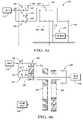
- FIG. 3 ashows a schematic lever diagram of a drive train incorporating a transfer case in accordance with a second alternative embodiment of the invention
- FIG. 3 bshows a schematic stick diagram corresponding with the lever diagram of FIG. 3 a;
- FIG. 4 ashows a schematic lever diagram of a drive train incorporating a transfer case in accordance with a third alternative embodiment of the invention.
- FIG. 4 bshows a schematic stick diagram corresponding with the lever diagram of FIG. 4 a.
- a lever diagram and stick diagramare shown, respectively, illustrating a vehicle 10 having a drive train 11 which includes a transfer case 12 for receiving torque from an input 14 and distributing the torque between the front and rear axles 16 , 18 of the vehicle 10 .
- the front and rear axleshave different axle ratios.
- the “axle ratio”is the relationship between the vehicle's drive shaft (or propeller shaft) and its wheel axle.
- a 4:1 or 4.0 axle ratiomeans that the drive shafts turns four times for every one time the axle turns. The higher the axle ratio, the greater the force that can be applied to the drive wheels for tasks like towing up a grade or pulling a boat out of the water.
- the front axlemay have a ratio of 3.15 and the rear axle may have a ratio of 4.10.
- the invention described hereinwould also be applicable to a vehicle having identical front and rear axle ratios.
- the transfer case 12includes the planetary gear set 20 which is a simple planetary gear set including first, second and third members.
- the first memberis the sun gear 22
- the second memberis the carrier 24
- the third memberis the ring gear 26 .
- First, second and third input clutches 30 , 32 , 34are connected to the sun gear 22 , carrier 24 , and ring gear 26 , respectively. Accordingly, the first input clutch 30 selectively connects the sun gear 22 with the input 14 , the second input clutch selectively connects the carrier 24 with the input 14 , and the third input clutch 34 selectively connects the ring gear 26 with the input 14 .
- the transfer case 12also includes first and second transfer chains 36 , 38 which are connected to each other and operatively engageable between the planetary gear set 20 and the front and rear axles 16 , 18 .
- first transfer chain 36is directly connected with the ring gear 26
- second transfer chain 38is directly connected with the sun gear 22 .
- the first transfer chain 36has a 1:1 chain ratio
- the second transfer chain 38has a ratio which is equal to the rear axle ratio divided by the front axle ratio (1.30:1 underdrive).
- the transfer case 12also includes a four wheel drive clutch 40 which is operative to selectively connect the front and rear axles 16 , 18 .
- the clutches 30 , 32 , 34 and 40may be dog clutches.
- Sample dog clutches for use with the present inventionare shown, for example, in U.S. Pat. No. 4,349,091, which is hereby incorporated by reference in its entirety.
- the first input clutch 30is engaged so that power flows from the input 14 through the first input clutch 30 and sun gear 22 to the rear axle 18 .
- four wheel drive lowmay be activated by engaging the four wheel drive clutch 40 .
- the second transfer chain 38is active.
- the second input clutch 32is engaged and power flows through the carrier 24 and is split between the sun gear 22 and ring gear 26 . From the sun gear 22 , power flows to the rear axle 18 . From the ring gear 26 , power flows through the chains 36 , 38 to the rear axle 18 .
- Four wheel drive midmay be achieved by then engaging the four wheel drive clutch 40 . Both transfer chains 36 , 38 are active in four wheel drive mid mode.
- the third input clutch 34is engaged so that power flows through the ring gear 26 , through both transfer chains 36 , 38 to the rear axle 18 .
- Four wheel drive highmay then be achieved by engaging the four wheel drive clutch 40 to connect the transfer chains 36 , 38 to the front axle 16 .
- the transfer case 12will be able to shift “on the fly” (i.e., with the axles spinning but no torque present) into and out of four wheel drive if a synchronizer is used on the four wheel drive dog clutch 40 . It will be necessary to come to a complete stop to shift from one ratio another by engaging and disengaging the clutches 30 , 32 , 34 , unless the shift is made at zero torque with the engine controlled to match the oncoming gear synchronous speed.
- FIGS. 2 a and 2 ba first alternative embodiment of the invention is shown. This configuration is similar to that shown in FIGS. 1 a and 1 b , except that the front and rear axles have identical axle ratios, and the transfer chain connections are swapped.
- the first alternative embodiment of the inventionis illustrated for a vehicle 110 incorporating a drive train 111 with a transfer case 112 for receiving torque from an input 114 and distributing the torque between the front and rear axles 116 , 118 .
- the transfer case 112includes a planetary gear set 120 having first, second and third members 122 , 124 , 126 .
- the first member 122is a ring gear
- the second member 124is a carrier
- the third member 126is a sun gear.
- a first input clutch 130selectively connects the input 114 with the ring gear 122
- a second input clutch 132selectively connects the input 114 with the carrier 124
- a third input clutch 134selectively connects the input 114 with the sun gear 126 .
- the transfer case 112also includes a first transfer chain 136 , which has an underdrive ratio, and is connected with the ring gear 122 .
- a second transfer chain 138has a 1:1 ratio and is connected with the sun gear 126 .
- a four wheel drive clutch 140is also provided for selectively connecting the front and rear axles 116 , 118 .
- the front and rear axleseach have an axle ratio of 3.15
- the first transfer chain 136has a 1.30:1 underdrive ratio.
- the four wheel drive clutch 140is a dog clutch having a synchronizer.
- the first input clutch 130is engaged, and power flows from the input 114 through the clutch 130 and ring gear 122 , and through the chains 136 , 138 to the rear axle 118 .
- Four wheel drive lowmay then be achieved by engaging the four wheel drive clutch 140 to connect the transfer chains 136 , 138 to the front axle 116 .
- the second input clutch 132is engaged, and power flows through the carrier 124 , and is split between the ring gear 122 and the sun gear 126 . From the sun gear 126 , power flows to the rear axle. From the ring gear 122 , power flows through the chains 136 , 138 to the rear axle. Four wheel drive mid may then be provided by engaging the four wheel drive clutch 140 to connect the front axle 116 with the transfer chains 136 , 138 .
- Rear wheel drive highmay be achieved by engaging the third input clutch 134 so that power flows through the clutch 134 and sun gear 126 directly to the rear axle 118 . This would be the maximum fuel economy mode because no chains are active.
- Four wheel drive highmay be achieved by engaging the four wheel drive clutch 140 and the third input clutch 134 for connecting the transfer chains 136 , 138 to the front axle 116 .
- FIGS. 3 a and 3 ba second alternative embodiment of the invention is shown. This embodiment is similar to that of FIGS. 1 a and 1 b except that the location of the four wheel drive clutch is changed.
- the vehicle 210incorporates a drive train 211 having a transfer case 212 for receiving torque from an input 214 and distributing the torque between the front and rear axles 216 , 218 of the vehicle 210 .
- the transfer case 212includes the planetary gear set 220 which is a simple planetary gear set including first, second and third members 222 , 224 , 226 .
- the first member 222is a sun gear
- the second member 224is a carrier
- the third member 226is a ring gear.
- the first input clutch 230selectively connects the input 214 with the sun gear 222 .
- the second input clutch 232selectively connects the input 214 with the carrier 224 .
- the third input clutch 234selectively connects the input 214 with the ring gear 226 .
- a first transfer chain 236 having a 1:1 chain ratiois connected between the ring gear 226 and the front axle 216 .
- a second transfer chain 238 having a ratio equal to the rear axle ratio divided by the front axle ratio (1.30:1 underdrive)is connected to the front axle 216 and the first transfer chain 236 .
- the rear axlehas a 4.10 axle ratio and the front axle has a 3.15 axle ratio.
- a four wheel drive clutch 240selectively connects the second transfer chain 238 with the rear axle 218 .
- the input clutch 230connects the input 214 with the sun gear 222 . Torque then flows directly to the rear axle 218 .
- Four wheel drive lowmay be activated by engaging the four wheel drive clutch 240 so that torque is carried to the front axle by the second transfer chain 238 .
- the second input clutch 232is engaged, and torque is split between the sun gear 222 and ring gear 226 .
- the sun gear 222drives the rear axle 218
- the ring gear 226drives the front axle 216 through the transfer chain 236 .
- Four wheel drivemay then be achieved by engaging the four wheel drive clutch 240 to connect the second transfer chain 238 with the rear axle 218 .
- Front wheel drive highis achieved by engaging the third input clutch 234 so that torque goes through the ring gear 226 to the front axle 216 through the transfer chain 236 . This is the maximum fuel economy mode.
- Four wheel drive highmay then be achieved by engaging the four wheel drive clutch 240 to connect the second transfer chain 238 with the rear axle 218 .
- FIGS. 4 a and 4 ba third alternative embodiment of the invention is shown.
- the vehicle 310includes a drive train 311 having a transfer case 312 for receiving torque from an input 314 and distributing the torque between the front and rear axles 316 , 318 of the vehicle 310 .
- the transfer case 312includes a planetary gear set 320 , having first, second and third members 322 , 324 , 326 .
- the first member 322is a ring gear
- the second member 324is a carrier
- the third member 326is a sun gear.
- the first input clutch 330selectively connects the input 314 with the ring gear 322 .
- the second input clutch 332selectively connects the input 314 with the carrier 324 .
- the third input clutch 334selectively connects the input 314 with the sun gear 326 .
- the first transfer chain 336has a 1.30:1 underdrive ratio, and is connected between the ring gear 322 and the front axle 316 .
- the second transfer chain 338has a 1:1 chain ratio and is connected to the first transfer chain 336 and the front axle 316 .
- the four wheel drive clutch 340selectively connects the first and second transfer chains 336 , 338 with the rear axle 318 .
- the first input clutch 330is engaged, and power travels through the ring gear 322 to the front axle 316 via the first transfer chain 336 .
- Four wheel drive lowmay be achieved by engaging the four wheel drive clutch 340 which connects the second transfer chain 338 to the rear axle 318 .
- All wheel drive midmay be achieved by engaging the second input clutch 332 .
- the planetary gear set 320splits the input torque between the ring gear 322 and the sun gear 326 .
- the ring gear 322drives the front axle 316 via the first transfer chain 336
- the sun gear 326drives the rear axle 318 directly.
- Four wheel drive midmay be achieved by engaging the four wheel drive clutch 340 and the clutch 332 .
- the four wheel drive clutch 340connects the rear axle 318 with the front axle 316 via the second transfer chain 338 .
- Rear wheel drive highmay be achieved by engaging the third input clutch 334 . Torque flows through the sun gear 326 directly to the rear axle 318 . This is the maximum fuel economy mode because no chains are active.
- Four wheel drive highmay be engaged by activating the four wheel drive clutch 340 and the third input clutch 334 .
- the four wheel drive clutch 340connects the rear axle 318 with the front axle 316 via the transfer chain 338 .
- the location of the ring gear 322 and sun gear 326may be swapped from the embodiment shown in FIG. 4 a to achieve different ratios.
- the simple planetary gear setcan be replaced by a compound planetary gear set.
- the compound gear set ring gearwill be equivalent to the carrier of the simple planetary gear set, and the sun gear and carrier of the compound planetary gear set can be interchanged depending on the choice of ring gear/sun gear tooth ratio.
Landscapes
- Engineering & Computer Science (AREA)
- Chemical & Material Sciences (AREA)
- Combustion & Propulsion (AREA)
- Transportation (AREA)
- Mechanical Engineering (AREA)
- Arrangement And Driving Of Transmission Devices (AREA)
Abstract
Description
Claims (21)
Priority Applications (2)
| Application Number | Priority Date | Filing Date | Title |
|---|---|---|---|
| US10/807,769US7163483B2 (en) | 2004-03-24 | 2004-03-24 | Three speed transfer case with two transfer chains |
| DE102005013253ADE102005013253B4 (en) | 2004-03-24 | 2005-03-22 | Transfer case with three gears and two transfer chains |
Applications Claiming Priority (1)
| Application Number | Priority Date | Filing Date | Title |
|---|---|---|---|
| US10/807,769US7163483B2 (en) | 2004-03-24 | 2004-03-24 | Three speed transfer case with two transfer chains |
Publications (2)
| Publication Number | Publication Date |
|---|---|
| US20050215377A1 US20050215377A1 (en) | 2005-09-29 |
| US7163483B2true US7163483B2 (en) | 2007-01-16 |
Family
ID=34990760
Family Applications (1)
| Application Number | Title | Priority Date | Filing Date |
|---|---|---|---|
| US10/807,769Expired - LifetimeUS7163483B2 (en) | 2004-03-24 | 2004-03-24 | Three speed transfer case with two transfer chains |
Country Status (2)
| Country | Link |
|---|---|
| US (1) | US7163483B2 (en) |
| DE (1) | DE102005013253B4 (en) |
Cited By (10)
| Publication number | Priority date | Publication date | Assignee | Title |
|---|---|---|---|---|
| US20060169515A1 (en)* | 2005-01-20 | 2006-08-03 | Borgwarner Inc. | Dual-chain transfer case |
| US20070131046A1 (en)* | 2005-12-14 | 2007-06-14 | Borgerson James B | Multi-speed transmission with differential gear set and countershaft gearing |
| US20080141810A1 (en)* | 2005-11-22 | 2008-06-19 | Fallbrook Technologies Inc. | Continuously variable transmission |
| US20100004088A1 (en)* | 2008-07-01 | 2010-01-07 | Wenthen David W | Dual clutch multi-speed transaxle |
| US8523738B2 (en) | 2011-01-21 | 2013-09-03 | Dana Heavy Vehicle Systems Group, Llc | Method of shifting a tandem drive axle having an inter-axle differential |
| US20140066242A1 (en)* | 2012-08-29 | 2014-03-06 | Greg SEBLANTE, SR. | Sprocket Box for Increasing the Gas Mileage of a Vehicle with an Automatic Transmission |
| CN103807387A (en)* | 2012-11-08 | 2014-05-21 | 通用汽车环球科技运作有限责任公司 | Triple clutch multi-speed transmission |
| US9102232B2 (en) | 2010-07-20 | 2015-08-11 | Dana Heavy Vehicle Systems Group, Llc | Drive axle system having a clutching device |
| US20190126735A1 (en)* | 2017-11-01 | 2019-05-02 | Hyundai Motor Company | Power transmission apparatus for vehicle |
| US11052745B1 (en)* | 2020-03-25 | 2021-07-06 | Ford Global Technologies, Llc | Powersplit hybrid transaxles |
Families Citing this family (4)
| Publication number | Priority date | Publication date | Assignee | Title |
|---|---|---|---|---|
| US7100472B2 (en)* | 2004-03-24 | 2006-09-05 | General Motors Corporation | Two speed transfer case having two transfer chains |
| US7231848B2 (en)* | 2004-06-24 | 2007-06-19 | Magna Powertrain Usa, Inc. | Transfer case with dual chain transfer mechanism |
| DE102015112850A1 (en)* | 2015-08-05 | 2017-02-09 | Peter Saßmannshausen | Drive arrangement for a motor vehicle having a drive front axle and a drive rear axle |
| US10207581B2 (en)* | 2017-01-19 | 2019-02-19 | Deere & Company | Multi-mode powertrain for work vehicle providing selective power distribution between axles |
Citations (13)
| Publication number | Priority date | Publication date | Assignee | Title |
|---|---|---|---|---|
| US3869940A (en)* | 1972-01-07 | 1975-03-11 | Gkn Transmissions Ltd | Vehicle with differential assembly |
| US4349091A (en) | 1980-11-12 | 1982-09-14 | Yanmar Diesel Engine Co., Ltd. | Synchronized dog clutch |
| US4553450A (en)* | 1982-02-22 | 1985-11-19 | Valeo | Transmission between a power input and an output shaft suitable for an automobile vehicle |
| US5342258A (en)* | 1991-08-16 | 1994-08-30 | Motion Sciences Inc. | Combinational incrementally variable transmissions and other gearing arrangements allowing maximum kinematic degrees of freedom |
| US5803858A (en)* | 1997-05-23 | 1998-09-08 | General Motors Corporation | Powertrain transmission with torque converter planetary gearing and a continuously variable transmission unit |
| US5833566A (en)* | 1997-05-19 | 1998-11-10 | Borg-Warner Automotive, Inc. | Speed reduction assembly with full disconnect for transfer cases and the like |
| US5853342A (en)* | 1997-03-11 | 1998-12-29 | New Venture Gear, Inc. | Offset transfer case |
| US5954612A (en)* | 1997-08-18 | 1999-09-21 | Dana Corporation | Multi-speed offset transfer case |
| US6045476A (en)* | 1999-06-01 | 2000-04-04 | General Motors Corporation | Transfer gearing apparatus for an all wheel drive |
| US6106428A (en)* | 1998-03-23 | 2000-08-22 | Ford Global Technologies, Inc. | Compact dual mode continually variable transmission |
| US6464612B2 (en)* | 2001-03-23 | 2002-10-15 | New Venture Gear, Inc. | Three-speed transfer case |
| US20040180749A1 (en)* | 2003-03-13 | 2004-09-16 | Haka Raymond J. | Two-speed transfer case with center differential |
| US6926634B2 (en)* | 2003-04-02 | 2005-08-09 | General Motors Corporation | All-wheel drive transfer case with different front and rear axle ratios |
Family Cites Families (1)
| Publication number | Priority date | Publication date | Assignee | Title |
|---|---|---|---|---|
| US4229996A (en)* | 1978-12-06 | 1980-10-28 | Ford Motor Company | Compact four speed automatic transmission |
- 2004
- 2004-03-24USUS10/807,769patent/US7163483B2/ennot_activeExpired - Lifetime
- 2005
- 2005-03-22DEDE102005013253Apatent/DE102005013253B4/ennot_activeExpired - Lifetime
Patent Citations (14)
| Publication number | Priority date | Publication date | Assignee | Title |
|---|---|---|---|---|
| US3869940A (en)* | 1972-01-07 | 1975-03-11 | Gkn Transmissions Ltd | Vehicle with differential assembly |
| US4349091A (en) | 1980-11-12 | 1982-09-14 | Yanmar Diesel Engine Co., Ltd. | Synchronized dog clutch |
| US4553450A (en)* | 1982-02-22 | 1985-11-19 | Valeo | Transmission between a power input and an output shaft suitable for an automobile vehicle |
| US5342258A (en)* | 1991-08-16 | 1994-08-30 | Motion Sciences Inc. | Combinational incrementally variable transmissions and other gearing arrangements allowing maximum kinematic degrees of freedom |
| US5853342A (en)* | 1997-03-11 | 1998-12-29 | New Venture Gear, Inc. | Offset transfer case |
| US5833566A (en)* | 1997-05-19 | 1998-11-10 | Borg-Warner Automotive, Inc. | Speed reduction assembly with full disconnect for transfer cases and the like |
| US5803858A (en)* | 1997-05-23 | 1998-09-08 | General Motors Corporation | Powertrain transmission with torque converter planetary gearing and a continuously variable transmission unit |
| US5954612A (en)* | 1997-08-18 | 1999-09-21 | Dana Corporation | Multi-speed offset transfer case |
| US6106428A (en)* | 1998-03-23 | 2000-08-22 | Ford Global Technologies, Inc. | Compact dual mode continually variable transmission |
| US6045476A (en)* | 1999-06-01 | 2000-04-04 | General Motors Corporation | Transfer gearing apparatus for an all wheel drive |
| US6464612B2 (en)* | 2001-03-23 | 2002-10-15 | New Venture Gear, Inc. | Three-speed transfer case |
| US6612959B2 (en)* | 2001-03-23 | 2003-09-02 | New Venture Gear, Inc. | Three-speed transfer case |
| US20040180749A1 (en)* | 2003-03-13 | 2004-09-16 | Haka Raymond J. | Two-speed transfer case with center differential |
| US6926634B2 (en)* | 2003-04-02 | 2005-08-09 | General Motors Corporation | All-wheel drive transfer case with different front and rear axle ratios |
Cited By (19)
| Publication number | Priority date | Publication date | Assignee | Title |
|---|---|---|---|---|
| US20060169515A1 (en)* | 2005-01-20 | 2006-08-03 | Borgwarner Inc. | Dual-chain transfer case |
| US20080141810A1 (en)* | 2005-11-22 | 2008-06-19 | Fallbrook Technologies Inc. | Continuously variable transmission |
| US20070131046A1 (en)* | 2005-12-14 | 2007-06-14 | Borgerson James B | Multi-speed transmission with differential gear set and countershaft gearing |
| US7311630B2 (en)* | 2005-12-14 | 2007-12-25 | Gm Global Technology Operations, Inc. | Multi-speed transmission with differential gear set and countershaft gearing |
| US20100004088A1 (en)* | 2008-07-01 | 2010-01-07 | Wenthen David W | Dual clutch multi-speed transaxle |
| US8123647B2 (en)* | 2008-07-01 | 2012-02-28 | Magna Powertrain Usa, Inc. | Dual clutch multi-speed transaxle |
| US9428050B2 (en) | 2010-07-20 | 2016-08-30 | Dana Heavy Vehicle Systems Group, Llc | Drive axle system having a clutching device |
| US9102232B2 (en) | 2010-07-20 | 2015-08-11 | Dana Heavy Vehicle Systems Group, Llc | Drive axle system having a clutching device |
| US9457655B2 (en) | 2010-07-20 | 2016-10-04 | Dana Heavy Vehicle Systems Group, Llc | Drive axle system having a clutching device |
| US9457657B2 (en) | 2010-07-20 | 2016-10-04 | Dana Heavy Vehicle Systems Group, Llc | Drive axle system having a clutching device |
| US9457656B2 (en) | 2010-07-20 | 2016-10-04 | Dana Heavy Vehicle Systems Group, Llc | Drive axle system having a clutching device |
| US8523738B2 (en) | 2011-01-21 | 2013-09-03 | Dana Heavy Vehicle Systems Group, Llc | Method of shifting a tandem drive axle having an inter-axle differential |
| US20140066242A1 (en)* | 2012-08-29 | 2014-03-06 | Greg SEBLANTE, SR. | Sprocket Box for Increasing the Gas Mileage of a Vehicle with an Automatic Transmission |
| US9163706B2 (en)* | 2012-08-29 | 2015-10-20 | Greg SEBLANTE, SR. | Sprocket box for increasing the gas mileage of a vehicle with an automatic transmission |
| CN103807387A (en)* | 2012-11-08 | 2014-05-21 | 通用汽车环球科技运作有限责任公司 | Triple clutch multi-speed transmission |
| US8747274B2 (en)* | 2012-11-08 | 2014-06-10 | Gm Global Technology Operations, Llc | Triple clutch multi-speed transmission |
| US20190126735A1 (en)* | 2017-11-01 | 2019-05-02 | Hyundai Motor Company | Power transmission apparatus for vehicle |
| US10538155B2 (en)* | 2017-11-01 | 2020-01-21 | Hyundai Motor Company | Power transmission apparatus for vehicle |
| US11052745B1 (en)* | 2020-03-25 | 2021-07-06 | Ford Global Technologies, Llc | Powersplit hybrid transaxles |
Also Published As
| Publication number | Publication date |
|---|---|
| DE102005013253A1 (en) | 2005-10-20 |
| US20050215377A1 (en) | 2005-09-29 |
| DE102005013253B4 (en) | 2010-01-21 |
Similar Documents
| Publication | Publication Date | Title |
|---|---|---|
| US7347801B2 (en) | Toroidal transmission | |
| US9895970B2 (en) | Multi-mode drive system for transaxle applications | |
| US7011596B2 (en) | Transfer case | |
| US7163483B2 (en) | Three speed transfer case with two transfer chains | |
| US9261180B2 (en) | Power split transmission | |
| US7500933B2 (en) | Transmission and drive train for a vehicle | |
| US7703353B2 (en) | Drive unit connected to a transmission output for producing forward and reverse device | |
| US6513399B2 (en) | Dual power flow counter shaft transmission | |
| US20140128196A1 (en) | Continuously variable power-split vehicle transmission | |
| US6942592B1 (en) | All wheel drive/four wheel drive transfer case with different front and rear axle ratios | |
| US7927246B2 (en) | Vehicular drive force distribution device | |
| CN105636813A (en) | Electrically variable transmission | |
| US5269732A (en) | Vehicle transmission with Ravigneaux central differential | |
| US11607950B2 (en) | Transmission system for a work vehicle | |
| US6840880B2 (en) | Power divider for motor vehicles comprising an off-road speed gear and a set-off-out-put | |
| US7416502B2 (en) | Hydrostatic mechanical power-split transmission | |
| US7101301B2 (en) | Two-speed transfer case with center differential | |
| AU2010295219B2 (en) | Transmission with hill hold feature | |
| US7062984B2 (en) | Vehicle powertrain with two-wheel and four-wheel drive ratios | |
| US6926634B2 (en) | All-wheel drive transfer case with different front and rear axle ratios | |
| US7100472B2 (en) | Two speed transfer case having two transfer chains | |
| GB2159110A (en) | Drive line for four wheel drive vehicle | |
| CN112297819A (en) | Four-wheel drive system and vehicle | |
| KR100279408B1 (en) | Power train for automatic transmission | |
| JPH068738A (en) | Drive device with center differential gear device |
Legal Events
| Date | Code | Title | Description |
|---|---|---|---|
| AS | Assignment | Owner name:GENERAL MOTORS CORPORATION, MICHIGAN Free format text:ASSIGNMENT OF ASSIGNORS INTEREST;ASSIGNOR:HAKA, RAYMOND J.;REEL/FRAME:014787/0272 Effective date:20040303 | |
| STCF | Information on status: patent grant | Free format text:PATENTED CASE | |
| AS | Assignment | Owner name:GM GLOBAL TECHNOLOGY OPERATIONS, INC., MICHIGAN Free format text:ASSIGNMENT OF ASSIGNORS INTEREST;ASSIGNOR:GENERAL MOTORS CORPORATION;REEL/FRAME:022117/0022 Effective date:20050119 Owner name:GM GLOBAL TECHNOLOGY OPERATIONS, INC.,MICHIGAN Free format text:ASSIGNMENT OF ASSIGNORS INTEREST;ASSIGNOR:GENERAL MOTORS CORPORATION;REEL/FRAME:022117/0022 Effective date:20050119 | |
| AS | Assignment | Owner name:UNITED STATES DEPARTMENT OF THE TREASURY, DISTRICT Free format text:SECURITY AGREEMENT;ASSIGNOR:GM GLOBAL TECHNOLOGY OPERATIONS, INC.;REEL/FRAME:022201/0610 Effective date:20081231 Owner name:UNITED STATES DEPARTMENT OF THE TREASURY,DISTRICT Free format text:SECURITY AGREEMENT;ASSIGNOR:GM GLOBAL TECHNOLOGY OPERATIONS, INC.;REEL/FRAME:022201/0610 Effective date:20081231 | |
| AS | Assignment | Owner name:CITICORP USA, INC. AS AGENT FOR BANK PRIORITY SECU Free format text:SECURITY AGREEMENT;ASSIGNOR:GM GLOBAL TECHNOLOGY OPERATIONS, INC.;REEL/FRAME:022553/0446 Effective date:20090409 Owner name:CITICORP USA, INC. AS AGENT FOR HEDGE PRIORITY SEC Free format text:SECURITY AGREEMENT;ASSIGNOR:GM GLOBAL TECHNOLOGY OPERATIONS, INC.;REEL/FRAME:022553/0446 Effective date:20090409 | |
| AS | Assignment | Owner name:GM GLOBAL TECHNOLOGY OPERATIONS, INC., MICHIGAN Free format text:RELEASE BY SECURED PARTY;ASSIGNOR:UNITED STATES DEPARTMENT OF THE TREASURY;REEL/FRAME:023124/0429 Effective date:20090709 Owner name:GM GLOBAL TECHNOLOGY OPERATIONS, INC.,MICHIGAN Free format text:RELEASE BY SECURED PARTY;ASSIGNOR:UNITED STATES DEPARTMENT OF THE TREASURY;REEL/FRAME:023124/0429 Effective date:20090709 | |
| AS | Assignment | Owner name:GM GLOBAL TECHNOLOGY OPERATIONS, INC., MICHIGAN Free format text:RELEASE BY SECURED PARTY;ASSIGNORS:CITICORP USA, INC. AS AGENT FOR BANK PRIORITY SECURED PARTIES;CITICORP USA, INC. AS AGENT FOR HEDGE PRIORITY SECURED PARTIES;REEL/FRAME:023127/0468 Effective date:20090814 Owner name:GM GLOBAL TECHNOLOGY OPERATIONS, INC.,MICHIGAN Free format text:RELEASE BY SECURED PARTY;ASSIGNORS:CITICORP USA, INC. AS AGENT FOR BANK PRIORITY SECURED PARTIES;CITICORP USA, INC. AS AGENT FOR HEDGE PRIORITY SECURED PARTIES;REEL/FRAME:023127/0468 Effective date:20090814 | |
| AS | Assignment | Owner name:UNITED STATES DEPARTMENT OF THE TREASURY, DISTRICT Free format text:SECURITY AGREEMENT;ASSIGNOR:GM GLOBAL TECHNOLOGY OPERATIONS, INC.;REEL/FRAME:023156/0052 Effective date:20090710 Owner name:UNITED STATES DEPARTMENT OF THE TREASURY,DISTRICT Free format text:SECURITY AGREEMENT;ASSIGNOR:GM GLOBAL TECHNOLOGY OPERATIONS, INC.;REEL/FRAME:023156/0052 Effective date:20090710 | |
| AS | Assignment | Owner name:UAW RETIREE MEDICAL BENEFITS TRUST, MICHIGAN Free format text:SECURITY AGREEMENT;ASSIGNOR:GM GLOBAL TECHNOLOGY OPERATIONS, INC.;REEL/FRAME:023162/0001 Effective date:20090710 Owner name:UAW RETIREE MEDICAL BENEFITS TRUST,MICHIGAN Free format text:SECURITY AGREEMENT;ASSIGNOR:GM GLOBAL TECHNOLOGY OPERATIONS, INC.;REEL/FRAME:023162/0001 Effective date:20090710 | |
| FPAY | Fee payment | Year of fee payment:4 | |
| AS | Assignment | Owner name:GM GLOBAL TECHNOLOGY OPERATIONS, INC., MICHIGAN Free format text:RELEASE BY SECURED PARTY;ASSIGNOR:UAW RETIREE MEDICAL BENEFITS TRUST;REEL/FRAME:025311/0770 Effective date:20101026 Owner name:GM GLOBAL TECHNOLOGY OPERATIONS, INC., MICHIGAN Free format text:RELEASE BY SECURED PARTY;ASSIGNOR:UNITED STATES DEPARTMENT OF THE TREASURY;REEL/FRAME:025245/0442 Effective date:20100420 | |
| AS | Assignment | Owner name:WILMINGTON TRUST COMPANY, DELAWARE Free format text:SECURITY AGREEMENT;ASSIGNOR:GM GLOBAL TECHNOLOGY OPERATIONS, INC.;REEL/FRAME:025327/0262 Effective date:20101027 | |
| AS | Assignment | Owner name:GM GLOBAL TECHNOLOGY OPERATIONS LLC, MICHIGAN Free format text:CHANGE OF NAME;ASSIGNOR:GM GLOBAL TECHNOLOGY OPERATIONS, INC.;REEL/FRAME:025780/0902 Effective date:20101202 | |
| FPAY | Fee payment | Year of fee payment:8 | |
| AS | Assignment | Owner name:GM GLOBAL TECHNOLOGY OPERATIONS LLC, MICHIGAN Free format text:RELEASE BY SECURED PARTY;ASSIGNOR:WILMINGTON TRUST COMPANY;REEL/FRAME:034371/0676 Effective date:20141017 | |
| MAFP | Maintenance fee payment | Free format text:PAYMENT OF MAINTENANCE FEE, 12TH YEAR, LARGE ENTITY (ORIGINAL EVENT CODE: M1553) Year of fee payment:12 |