US7162731B2 - Radio frequency characterization of cable plant and corresponding calibration of communication equipment communicating via the cable plant - Google Patents
Radio frequency characterization of cable plant and corresponding calibration of communication equipment communicating via the cable plantDownload PDFInfo
- Publication number
- US7162731B2 US7162731B2US10/072,479US7247902AUS7162731B2US 7162731 B2US7162731 B2US 7162731B2US 7247902 AUS7247902 AUS 7247902AUS 7162731 B2US7162731 B2US 7162731B2
- Authority
- US
- United States
- Prior art keywords
- upstream
- downstream
- channel
- test signal
- information
- Prior art date
- Legal status (The legal status is an assumption and is not a legal conclusion. Google has not performed a legal analysis and makes no representation as to the accuracy of the status listed.)
- Expired - Lifetime, expires
Links
Images


Classifications
- H—ELECTRICITY
- H04—ELECTRIC COMMUNICATION TECHNIQUE
- H04N—PICTORIAL COMMUNICATION, e.g. TELEVISION
- H04N21/00—Selective content distribution, e.g. interactive television or video on demand [VOD]
- H04N21/40—Client devices specifically adapted for the reception of or interaction with content, e.g. set-top-box [STB]; Operations thereof
- H04N21/41—Structure of client; Structure of client peripherals
- H04N21/426—Internal components of the client ; Characteristics thereof
- H04N21/42676—Internal components of the client ; Characteristics thereof for modulating an analogue carrier signal to encode digital information or demodulating it to decode digital information, e.g. ADSL or cable modem
- H—ELECTRICITY
- H04—ELECTRIC COMMUNICATION TECHNIQUE
- H04L—TRANSMISSION OF DIGITAL INFORMATION, e.g. TELEGRAPHIC COMMUNICATION
- H04L1/00—Arrangements for detecting or preventing errors in the information received
- H04L1/24—Testing correct operation
- H—ELECTRICITY
- H04—ELECTRIC COMMUNICATION TECHNIQUE
- H04L—TRANSMISSION OF DIGITAL INFORMATION, e.g. TELEGRAPHIC COMMUNICATION
- H04L27/00—Modulated-carrier systems
- H04L27/0002—Modulated-carrier systems analog front ends; means for connecting modulators, demodulators or transceivers to a transmission line
- H—ELECTRICITY
- H04—ELECTRIC COMMUNICATION TECHNIQUE
- H04L—TRANSMISSION OF DIGITAL INFORMATION, e.g. TELEGRAPHIC COMMUNICATION
- H04L27/00—Modulated-carrier systems
- H04L27/32—Carrier systems characterised by combinations of two or more of the types covered by groups H04L27/02, H04L27/10, H04L27/18 or H04L27/26
- H04L27/34—Amplitude- and phase-modulated carrier systems, e.g. quadrature-amplitude modulated carrier systems
- H—ELECTRICITY
- H04—ELECTRIC COMMUNICATION TECHNIQUE
- H04N—PICTORIAL COMMUNICATION, e.g. TELEVISION
- H04N21/00—Selective content distribution, e.g. interactive television or video on demand [VOD]
- H04N21/60—Network structure or processes for video distribution between server and client or between remote clients; Control signalling between clients, server and network components; Transmission of management data between server and client, e.g. sending from server to client commands for recording incoming content stream; Communication details between server and client
- H04N21/61—Network physical structure; Signal processing
- H04N21/615—Signal processing at physical level
- H—ELECTRICITY
- H04—ELECTRIC COMMUNICATION TECHNIQUE
- H04N—PICTORIAL COMMUNICATION, e.g. TELEVISION
- H04N21/00—Selective content distribution, e.g. interactive television or video on demand [VOD]
- H04N21/60—Network structure or processes for video distribution between server and client or between remote clients; Control signalling between clients, server and network components; Transmission of management data between server and client, e.g. sending from server to client commands for recording incoming content stream; Communication details between server and client
- H04N21/63—Control signaling related to video distribution between client, server and network components; Network processes for video distribution between server and clients or between remote clients, e.g. transmitting basic layer and enhancement layers over different transmission paths, setting up a peer-to-peer communication via Internet between remote STB's; Communication protocols; Addressing
- H04N21/647—Control signaling between network components and server or clients; Network processes for video distribution between server and clients, e.g. controlling the quality of the video stream, by dropping packets, protecting content from unauthorised alteration within the network, monitoring of network load, bridging between two different networks, e.g. between IP and wireless
- H04N21/64723—Monitoring of network processes or resources, e.g. monitoring of network load
- H—ELECTRICITY
- H04—ELECTRIC COMMUNICATION TECHNIQUE
- H04N—PICTORIAL COMMUNICATION, e.g. TELEVISION
- H04N7/00—Television systems
- H04N7/16—Analogue secrecy systems; Analogue subscription systems
- H04N7/173—Analogue secrecy systems; Analogue subscription systems with two-way working, e.g. subscriber sending a programme selection signal
- H04N7/17309—Transmission or handling of upstream communications
- H—ELECTRICITY
- H03—ELECTRONIC CIRCUITRY
- H03G—CONTROL OF AMPLIFICATION
- H03G3/00—Gain control in amplifiers or frequency changers
- H03G3/20—Automatic control
- H03G3/30—Automatic control in amplifiers having semiconductor devices
- H03G3/3036—Automatic control in amplifiers having semiconductor devices in high-frequency amplifiers or in frequency-changers
- H—ELECTRICITY
- H04—ELECTRIC COMMUNICATION TECHNIQUE
- H04L—TRANSMISSION OF DIGITAL INFORMATION, e.g. TELEGRAPHIC COMMUNICATION
- H04L25/00—Baseband systems
- H04L25/02—Details ; arrangements for supplying electrical power along data transmission lines
- H04L25/0202—Channel estimation
- H04L25/022—Channel estimation of frequency response
- H—ELECTRICITY
- H04—ELECTRIC COMMUNICATION TECHNIQUE
- H04L—TRANSMISSION OF DIGITAL INFORMATION, e.g. TELEGRAPHIC COMMUNICATION
- H04L25/00—Baseband systems
- H04L25/02—Details ; arrangements for supplying electrical power along data transmission lines
- H04L25/0202—Channel estimation
- H04L25/0224—Channel estimation using sounding signals
- H04L25/0226—Channel estimation using sounding signals sounding signals per se
Definitions
- the present inventionrelates to information cable plants employed for telecommunications, and more particularly, to characterization of cable plants and calibration of associated communication equipment.
- Broadband contentincludes multiple types of entertainment programming, communications and data, such as broadcast television channels, video on demand, streaming video, multimedia data, internet access, voice-over-IP, etc.
- DSLdigital subscriber line
- ADSLasymmetrical DSL
- HFChybrid fiber coax
- WLL2-way wireless local loop
- Cable modem systems for delivery of data services using Data-Over-Cable Service Interface Specificationsutilize the television broadcast spectrum and television technology to broadcast so-called broadband data to subscribers.
- DOCSISData-Over-Cable Service Interface Specifications
- One problem with delivery of broadband data (video on demand, streaming video, etc.) using existing HFC networksis the limitation on available delivery spectrum.
- the television data delivery systemshave been established to deliver data to subscribers over a television broadcast spectrum extending from approximately 15 Megahertz (MHz) to approximately 860 MHz. Delivery of analog television downstream to the subscriber occupies the spectrum between approximately 54 MHz to 550 MHz, which leaves a relatively small range of spectrum for the delivery of digital information over HFC cable modem systems.
- the diplex filter separating the downstream from the upstreamis located within the frequency range of approximately 42 to 54 MHz in an extended sub-split frequency plan, which is common for most consumer-based HFC systems. Therefore, the two effective delivery frequency ranges using typical consumer-based HFC systems are those between approximately 5–42 MHz (upstream) and those between approximately 550–860 MHz (downstream). Other frequency plans are known in which the diplex filter is shifted in the applicable frequency spectrum.
- DOCSISis an existing standard that specifies the methodology for delivering data services over an HFC plant.
- DOCSISdefines a Cable Modem Termination System (CMTS), which is an entity used to deliver data services over an HFC network from a central distribution point.
- CMTSCable Modem Termination System
- DOCSIS systemsuse a shared frequency channel to broadcast all data to every downstream subscriber, and thus are limited in data throughput capacity.
- Newer standards and technologiesare emerging that provide significantly greater throughput capacity than existing cable modem systems. For example, one system being developed utilizes multiple channels for data transfer and uses more sophisticated modulation techniques to increase throughput per channel. Each channel may further be subdivided into dedicated sub-streams to individual subscribers.
- RF characterization of a cable plant and corresponding calibration of communication equipmentprovides several benefits and advantages.
- the diagnostic and calibration capabilitymay be built into the cable communication equipment being installed.
- the diagnostic informationis used to calibrate equipment during installation and periodically during normal operation or in the event of malfunction or failure.
- the diagnostic procedureprovides early and real-time characterization of the underlying cable network, dynamically establishes a system RF link budget, and significantly reduces installation time and the amount of equipment and human errors in the field.
- the diagnostic systemprovides invaluable network characterization information and facilitates the installation process.
- the diagnostic systemfurther may be used at any time during normal operation or in the event of network problems.
- the installation process for each gatewayis streamlined and simplified and the existence of multiple gateways distributed on multiple subscriber links establishes a powerful diagnostic tool to isolate and locate network problems. In this manner, the diagnostic system is able to characterize multiple downstream channels since multiple gateways can occupy the same channel.
- a bi-directional cable communication systemis configured to communicate information via a cable network and incorporates a diagnostic and calibration system.
- the cable communication systemincludes a first transceiver coupled at a selected point of distribution of the cable network and a second transceiver coupled to the cable network at a selected downstream location.
- the first transceivertransmits a downstream test signal having predetermined characteristics on the cable network in a selected downstream channel at a predetermined power level.
- the first transceiverreceives corresponding downstream diagnostic information in a selected upstream channel from the second transceiver, where the downstream diagnostic information includes a downstream power loss metric.
- the first transceivercalibrates downstream transmission power based on the downstream power loss.
- the second transceiverreceives the downstream test signal in the selected downstream channel and compares the received signal with the predetermined characteristics and power level to determine the downstream diagnostic information, which includes a downstream power loss metric and a downstream noise level metric for the selected downstream channel.
- the second transceivertransmits the downstream diagnostic information in a selected upstream channel.
- the second transceiveralso transmits an upstream test signal with predetermined characteristics on the cable network in the selected upstream channel at a predetermined power level, and receives corresponding upstream power information in the downstream channel.
- the second transceivercalibrates upstream transmission power based on the upstream power information.
- the first transceiverreceives the upstream test signal and compares the received upstream test signal with the predetermined characteristics and power level to determine corresponding upstream diagnostic information.
- the upstream diagnostic informationincludes an upstream power loss metric and an upstream noise level metric in the upstream channel.
- the first transceiverdetermines the upstream power information based on the upstream power loss metric, and transmits the power information in the selected downstream channel if the output power of the second transceiver needs to be adjusted.
- the first transceivermay include diagnostic logic that determines if downstream communication using a selected downstream modulation scheme is realizable based on the downstream noise level. The diagnostic logic also determines whether upstream communication using a selected upstream modulation scheme is realizable based on the upstream noise level.
- the downstream and upstream noise level metricsmay each comprise a signal to noise ratio.
- the upstream and downstream modulation schemesmay be based on quadrature-amplitude modulation (QAM), such as QAM-256 for the downstream modulation scheme and QAM-16 for the upstream modulation scheme.
- the predetermined characteristics for both the downstream and upstream test signalsmay include frequency, timing and amplitude information.
- the downstream test signalmay be a tone based on a selected constellation point of a QAM-256 constellation and the upstream test signal may be a tone based on a selected constellation point of a QAM-16 constellation.
- the first transceivermay further be configured to determine upstream spectrum information from the upstream test signal.
- the diagnostic logicmay perform a frequency transform of the upstream spectrum information to determine upstream frequency characteristics.
- the diagnostic logicmay perform a Fast-Fourier Transform (FFT) of the upstream spectrum information to determine the frequency characteristics of the upstream communication bandwidth.
- FFTFast-Fourier Transform
- a communication systemis configured to communicate across a cable system having a point of distribution and at least one downstream subscriber cable link.
- the communication systemis further configured to operate in a diagnostic and calibration mode.
- the communication systemincludes a switch router coupled at the point of distribution, and one or more gateways coupled to corresponding downstream subscriber cable links.
- the switch routertransmits a predetermined downstream test signal at a predetermined power level using a selected downstream channel, and receives corresponding downstream channel diagnostic information including downstream channel power loss.
- the switch routercalibrates transmission power for the downstream channel based on the downstream channel power loss.
- the switch routeralso receives an upstream test signal and determines corresponding upstream channel power loss and noise level, and transmits corresponding upstream channel power information on the selected downstream channel.
- Each gatewaytransmits a predetermined upstream test signal at a predetermined power level in a selected upstream channel, and receives corresponding upstream channel power information.
- Each gatewaycalibrates transmission power of its upstream channel based on the upstream channel power information. The gateway farther receives a downstream test signal and determines downstream channel diagnostic information including downstream channel power loss and noise level, and transmits the downstream channel diagnostic information in the selected upstream channel.
- the switch router and the plurality of gatewayscollectively operate to perform diagnostics and to calibrate a corresponding pair of downstream and upstream channels for each gateway.
- the switch routermay further be used to determine if downstream communication is realizable using the selected downstream modulation scheme for the selected downstream channel based on the measured downstream noise level. Also, the switch router determines if upstream communication is realizable using the selected upstream modulation scheme for the selected upstream channel based on the measured upstream noise level.
- the switch routermay include a controller, a downstream modulator, a radio frequency (RF) downstream transmitter, an RF upstream receiver and an upstream demodulator.
- the switch router controlleroperates the switch router in the diagnostic mode.
- the downstream modulatoroperates according to a selected downstream modulation scheme for providing IF modulation information, and generates the predetermined downstream test signal as a tone based on a predetermined constellation point.
- the RF downstream transmitterconverts the IF modulation information into a corresponding RF signal and transmits the RF signal in a downstream channel at a power level selected by the switch router controller.
- the RF upstream receiveris tuned to a selected upstream channel to convert received upstream RF signals into an IF signals.
- the upstream demodulatoroperates according to a selected upstream modulation scheme, controls receiver gain and provides a gain level indicative thereof, and determines the upstream channel power loss and noise level based on the received upstream test signal.
- the switch router controllerdetermines upstream power information and transmits the upstream power information in the selected downstream channel via the downstream modulator.
- the selected downstream modulation schememay be QAM-256 and the selected upstream modulation scheme may be QAM-16.
- the upstream demodulatormay farther be configured to determine upstream spectrum information using the received upstream test signal.
- the switch router controllerincludes a processor that performs a frequency transform on the upstream spectrum information.
- Each gatewaymay include a tuner, a receiver gain control circuit, a downstream demodulator, a gateway controller, an upstream modulator, and a programmable gain device.
- the tuneris tuned to a selected downstream channel to receive and convert RF signals into corresponding IF signals.
- the receiver gain control circuitcontrols gain of received IF signals and generates a gain level value indicative thereof.
- the downstream demodulatoroperates according to the selected downstream modulation scheme to demodulate IF signals.
- the downstream demodulatoralso compares a downstream test signal with a predetermined downstream modulation constellation point to determine an error value.
- the gateway controllerdetermines downstream channel diagnostic information including downstream power loss and noise level of a selected downstream channel based on the gain level value and the error value.
- the gateway controlleralso forwards the downstream channel diagnostic information for upstream transmission, and programs a gain control value to calibrate upstream power level based on received upstream power information.
- the upstream modulatoroperates according to the selected upstream modulation scheme and generates an RF upstream test signal based on a predetermined upstream modulation constellation point.
- the upstream modulatoralso converts the downstream channel diagnostic information into an RF diagnostic signal and transmits the RF diagnostic signal in the selected upstream channel.
- the programmable gain deviceamplifies signals transmitted by the upstream modulator according to the programmed gain control value.
- a method of characterizing a cable network and calibrating a bi-directional cable communication systemincludes transmitting a downstream test signal from a point of distribution on the cable network in a selected downstream channel at a predetermined downstream power level, where the downstream test signal has predetermined characteristics, receiving the downstream test signal in the selected downstream channel at a downstream location, determining a downstream power loss metric of the downstream channel by comparing a power level of the received downstream test signal with the predetermined downstream power level, transmitting downstream diagnostic information including the downstream power loss and downstream noise level metrics in a selected upstream channel, calibrating downstream transmit power at the point of distribution based on the downstream power loss metric, transmitting an upstream test signal from the downstream location on the cable network in a selected upstream channel at a second predetermined power level, where the upstream test signal has second predetermined characteristics, receiving the upstream test signal in the selected upstream channel at the point of distribution, determining an upstream power loss metric of the upstream channel by comparing a power level of the received upstream test signal with the pre
- the methodmay further include determining a downstream noise level metric of the downstream channel by comparing the predetermined characteristics of the downstream test signal with corresponding characteristics of the received downstream test signal and determining, based on the downstream noise level metric, if downstream communication is realizable using a selected downstream modulation scheme on the selected downstream channel.
- the methodmay further include determining an upstream noise level metric of the upstream channel by comparing the second predetermined characteristics with corresponding characteristics of the received upstream test signal, and determining, based on the upstream noise level metric, if upstream communication is realizable using a selected upstream modulation scheme on the selected upstream channel.
- the methodmay further include generating a test tone based on the selected downstream modulation scheme to develop the downstream test signal, and generating a test tone based on the selected upstream modulation scheme to develop the upstream test signal.
- Generating a test tonemay comprise selecting a constellation point of a selected modulation scheme, in which the selected constellation point has known amplitude, frequency and timing information.
- Determining downstream and upstream power loss metricsmay each comprise performing gain control relative to a target power level, generating a gain error level, and comparing the generated gain error level with a corresponding predetermined power level.
- Determining downstream and upstream noise level metricsmay each comprise comparing frequency, timing and amplitude information between a received test signal and predetermined frequency, timing and amplitude information and generating an error value.
- Determining if downstream and upstream communication is realizablemay each comprise comparing a determined noise level metric with a predetermined threshold signal to noise ratio.
- the calibrating upstream transmit power at the downstream locationmay comprise programming a gain level value that controls a programmable gain amplifier.
- the methodmay further include determining an upstream spectrum using the received upstream test signal, and performing a frequency transform function on the upstream spectrum.
- the frequency transform functionprovides frequency spectrum information for the upstream frequency bandwidth.
- FIG. 1is a block diagram of a communication network architecture according to an exemplary embodiment of the present invention.
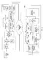
- FIG. 2is a simplified block diagram of a switch router located at an appropriate point of insertion of the communication system of FIG. 1 , such as within the headend, and an exemplary gateway located at any selected subscriber location.
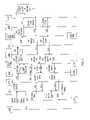
- FIG. 3is a signal flow diagram illustrating a diagnostic and calibration procedure according to an embodiment of the present invention.
- FIG. 1is a block diagram of an exemplary communication system 100 with an exemplary network architecture.
- One or more sources 101are coupled via appropriate communication links 102 to deliver source information to a headend 103 , which distributes the source information to one or more distribution hubs 105 via respective communication links 104 .
- Each distribution hub 105further distributes source information to one or more nodes 107 via communication links 106 , where each node 107 in turn distributes the source information to one or more subscriber locations 109 via subscriber links 108 .
- bi-directional communicationis supported in which upstream subscriber information from any one or more of the subscriber locations 109 is delivered to the corresponding distribution hub 105 via the corresponding subscriber links 108 .
- the subscriber informationmay be delivered to the headend 103 , or to an appropriate source 101 , by the corresponding distribution hub 105 . Again, depending upon the nature of the subscriber information and the network architecture, the subscriber information may be further delivered to an appropriate source 101 by the headend 103 .
- the headend 103may generically be referred to as points of distribution for source and subscriber information.
- Each point of distributionsupports a successively smaller geographic area.
- the headend 103may support a relatively large geographic area, such as an entire metropolitan area or the like, which is further divided into smaller areas, each supported by a distribution hub 105 .
- the areas supported by each distribution hub 105is further divided into smaller areas, such as neighborhoods within the metropolitan area, each supported by a corresponding node 107 .
- sources 101are contemplated, such as one or more computer or data networks 111 , one or more telephony networks 113 , one or more satellite communication systems 115 , one or more off-air antenna systems 116 (e.g. microwave tower), etc.
- the computer networks 111may include any type of local, wide area or global computer networks, both public and private, such as including the Internet or the like.
- the telephony networks 113may include the public switched telephone network (PSTN) or other public or private telephony networks.
- PSTNpublic switched telephone network
- the satellite communication systems 115 and/or the antenna systems 116may be employed for reception and delivery of any type of information, such as television broadcast content or the like.
- the headend 103may also include video on demand (VOD) equipment (not shown).
- VODvideo on demand
- any one or more of the sources 101may be coupled directly to one or more of the distribution hubs 105 , in the alternative, or in addition to being coupled to the headend 103 , by communication links 102 ′.
- the computer networks 111 and the telephony networks 113are shown coupled to a distribution hub 105 in addition or in the alternative.
- the headend 103includes appropriate equipment for data transmission, such as, for example, internal servers, firewalls, IP routers, signal combiners, channel re-mappers, etc.
- Each of the communication linksmay be any appropriate media, such as electrical or fiber optic cables or wireless or the like, or any combination of media, such as electrical and optical media and wireless or multiple optical media, etc.
- each of the communication links 102 and 102 ′includes optical media for communicating analog information, such as between the headend 103 and a satellite communication system 115 or an antenna system 116 , and/or 1000Base-X Ethernet for communicating digital information between the headend 103 and any computer or telephony network 111 , 113 .
- the communication links 106comprise optical fibers or cables that are distributed between each node 107 and a corresponding distribution hub 105 .
- the network architecturemay employ a hybrid fiber coax (HFC) distribution network in which the subscriber links 108 comprises coaxial cables that are distributed from each node 107 to the respective subscriber locations 109 .
- the nodes 107are optical nodes for conversion between optical and electrical formats.
- the communication links 104may also comprise optical links, such as, for example, SONET (Synchronous Optical Network) links or the like. It is understood that any known or future developed media is contemplated for each communication link.
- each node 107receives an optical signal from an upstream point of distribution, converts the optical signal to an electrical signal and distributes the combined electrical signal over a coaxial cable to each of several subscriber locations 109 of a corresponding geographic serving area. Subscriber information is delivered to each node 107 as an electrical signal, which the node 107 converts into an optical signal, and delivers that optical signal upstream to the corresponding distribution hubs 105 via the corresponding communication links 106 .
- HFChybrid fiber coax
- Each subscriber location 109includes customer premises equipment (CPE) or the like, which further includes a subscriber gateway 203 ( FIG. 2 ) that separates upstream and downstream information, tunes, de-modulates, decodes and selects source information addressed or otherwise intended for the particular subscriber location 109 .
- the gateway 203may be incorporated within, or otherwise coupled to other subscriber devices, such as set-top boxes, cable modems, etc.
- the gateway 203 at each subscriber location 109includes a modulating device or the like that encodes, modulates and up-converts subscriber information into RF signals.
- the gateway 203 at each of the subscriber locations 109asserts an upstream RF signal onto the corresponding subscriber link 108 , which delivers the signal to a corresponding node 107 .
- a separate channel of the portion of the cable spectrum used for upstream communicationsmay be assigned to each of the subscriber locations 109 to prevent interference with downstream communications.
- the upstream RF signalsare delivered to the node 107 , which includes an upstream optical transceiver or the like that converts the subscriber RF signals to an optical signal.
- laser in the node 107may be used to convert the return signal to an optical signal and send the optical return signal to an optical receiver at the distribution hub 105 over another fiber optic cable.
- the source and subscriber informationmay include any combination of video, audio or other data signals and the like, which may be in any of many different formats.
- the source informationmay originate as fixed- or variable-size frames, packets or cells, such as Internet Protocol (IP) packets, Ethernet frames, Asynchronous Transfer Mode (ATM) cells, etc., as provided to the distribution hubs 105 .
- IPInternet Protocol
- ATMAsynchronous Transfer Mode
- Any such type of digital information in fixed- or variable-sized frames, packets or cells for both up and downstream datais referred to herein as “packetized” data.
- the packetized dataincludes one or more destination addresses or the like indicating any one or more specific subscriber devices at the subscriber locations 109 or other locations in the communication system 100 .
- packetized datais converted and delivered to the subscriber locations 109 employing Time Division Multiplexing (TDM) over broadband modulation.
- TDMTime Division Multiplexing
- the gateway 203 at each subscriber location 109includes the appropriate communication equipment to tune, demodulate and decode the TDM over broadband information to deliver the original content to one or more subscriber devices.
- Upstream subscriber packetized datais converted to frames or codewords in a similar manner.
- the upstream datais transmitted in bursts using a Time Division Multiple Access (TDMA) over Frequency Division Multiple Access (FDMA) scheme.
- TDMATime Division Multiple Access
- FDMAFrequency Division Multiple Access
- Each gateway 203transmits data and information in one or more assigned timeslots of at least one upstream frequency channel.
- Modulation techniquesmay include, for example, Frequency Shift Keying (FSK), Quadrature Phase-Shift Keying (QPSK), as well various types of Quadrature Amplitude Modulation (QAM), such as QAM 16, QAM 64, QAM 256, etc., among other modulation techniques.
- each frequency or “physical” channelmay have any predetermined bandwidth, such as 1 MHz, 3 MHz, 6 MHz, 12 MHz, etc., or slight variations thereof
- Each subscriber channeltypically includes a separate downstream and upstream channel separated in frequency, where the corresponding downstream and up stream channels may have the same or different frequency band width.
- the modulation technique employed for each downstream channelmay be similar or substantially different than the modulation technique employed for each upstream channel.
- the communication system 100is an HFC system that supports analog television broadcast transmission in which broadcast television channels are allocated to a particular frequency range of the overall available RF cable television spectrum (54 MHz–550 MHz). The remaining portion of the RF cable television spectrum is utilized to assign data channels including any combination of downstream and upstream channels.
- some HFC systemsimplement an extended sub-split frequency plan with a return band, which extends from 5 to 42 MHz, and a forward band, which extends from 54 to 750–860 MHz. It is understood that the particular frequency ranges described herein are exemplary only and that any frequency allocation scheme may be employed depending upon the desired configuration.
- the entire forward bandis segmented into 6 MHz channels according to the channelization plan implemented by the particular HFC network operator. For typical HFC plants supporting analog television broadcasts, 80 analog channels are transmitted in the forward band between 54 and 550 MHz. In such HFC networks, satellite signals and local analog stations are mapped to 6 MHz broadcast channels within the forward band at the headend 103 . Each 6 MHz forward band channel may contain an analog channel or one or more digital channels that are MPEG encoded.
- the return band (5–42 MHz) and the remaining forward band spectrum, including frequency ranges 550 to 750–860 MHz,is allocated to subscriber digital channels and/or data transmission for dedicated bandwidth to each subscriber location 109 .
- the frequency range 550 to 860 MHzis allocated for downstream channels and the frequency range 5 to 42 MHz is allocated for upstream channels.
- the frequency range 42–54 MHzis the location of a diplex filter that separates the downstream communications from the upstream communications.
- Diplex filtersallow for bi-directional communication over the shared HFC fiber and coaxial medium.
- the basic diplex filterconsists of a high pass and a low pass filter in parallel followed by an amplifier that are both driven from the same source.
- a substantial portion or the entire available spectrumis utilized to assign channels to each of the subscribers.
- an all-digital HFC networkfor example, there is no channel-on-channel carry requirement of matching analog channel frequency assignments to off-air frequencies (i.e. broadcasting cable channel 2 at 54 MHz over the HFC plant, in accordance with the HRC frequency plan).
- the filter frequency settings on the diplex filtermay be adjusted upwards in an all-digital network from that of the extended sub-split frequency plan to increase spectrum available for upstream communications.
- mid-split and high-split frequency planswhich are suitable for an all-digital network, allocate the 5–86 MHz and 5–186 MHz ranges, respectively, for upstream transmission. Consequently, all-digital networks allow more upstream bandwidth for interactive services, such as data over cable services, packet telephony, video conferencing, interactive gaming, etc.
- the relatively large bandwidth otherwise consumed by television broadcast informationis available for channel assignments. This provides a significant advantage since a very “clean” portion of the RF spectrum (e.g., 50–300 MHz) may be employed for data communication.
- Each usermay be allocated a greater amount of bandwidth or a greater number of subscribers may be served by each coaxial cable.
- a different frequency spectrum splitmay be utilized to increase upstream bandwidth availability, and to enable a more symmetrical configuration with more equal downstream and upstream bandwidth allotments.
- Embodiments with a smaller geographical serving areaintroduce less noise and need less amplification so that each subscriber location 109 receives a cleaner signal, increasing overall reliability and throughput.
- FIG. 2is a simplified block diagram of a switch router 201 located at an appropriate point of insertion of the communication system 100 and an exemplary gateway 203 located at any selected subscriber location 109 .
- the point of insertionmay be at any one of the points of distribution, such as the headend 103 , any hub 105 or any node 107 .
- the switch router 201 and gateway 203communicate with each other via an intermediate network 205 , which represents any corresponding intermediate network equipment and communication links between the switch router 201 and gateway 203 depending upon the particular point of insertion.
- the intermediate network 205at least includes corresponding intermediate communication links 106 and 108 , any intermediate network equipment located at the point of insertion and an intermediate node 107 .
- the intermediate network 205includes an intermediate distribution hub 105 and associated links. It is appreciated, however, that the intermediate network 205 is not limited to the exemplary communication system 100 , but instead includes any newly established or pre-existing cable plant incorporating new or legacy cable equipment including cable plants established for cable television (CATV) or any HFC plant.
- CATVcable television
- the intermediate network 205is often uncharacterized in that certain communication parameters and characteristics may not be known at the time that cable communication equipment is installed. Such parameters and characteristics of the applicable communication frequency ranges may include, for example, frequency spectrum, noise level metrics (such as carrier or signal to noise ratio), power loss metrics, etc. It is also desired to know the available frequency ranges and associated guard bands necessary for an existing cable network. Even if some of these parameters or characteristics have been measured or are otherwise known, they may dynamically change due to weather conditions, subscriber interferences and connections and/or failure of network links or equipment.
- the switch router 201 and gateway 203are configured according to embodiments of the present invention to measure these and other parameters of the intermediate network 205 , which enables reduced installation time, provides early and real time characterization of any CATV or HFC plant, dynamically establishes the system RF link budget, and reduces the amount of equipment and human errors in the field during installation and over time.
- the switch router 201 and gateway 203include a diagnostic system that performs diagnostic procedures during installation and at any time thereafter. As described further below, the diagnostic information may be used to calibrate the communication equipment and to provide additional characterization information useful to cable network operators.
- the switch router 201includes one or more network interface modules (NIMs) 207 , each configured to interface and terminate links of a corresponding network communication architecture to establish bi-directional communications with devices compatible with the particular architecture.
- NIMsnetwork interface modules
- the NIM 207may be configured to interface an Ethernet architecture (e.g, 100Base-TX, 1000Base-X, 1000Base-SX, 1000Base-LX, 1000Base-LH, etc.).
- Ethernet architecturee.g, 100Base-TX, 1000Base-X, 1000Base-SX, 1000Base-LX, 1000Base-LH, etc.
- Each NIM 207is directly or indirectly linked to any desired combination of local or upstream devices, such as the computer or data networks 111 , the telephony networks 113 , the satellite communication systems 115 , the antenna systems 116 , etc., for providing LAN, MAN or WAN connectivity.
- the NIM 207enables bi-directional communications between a user device 209 , such as a laptop computer or the like, and a network processor (NP) 211 .
- the NP 211generally performs packet processing, including forwarding, link layer framing and physical layer encoding for bi-directional transmission of packetized information, as well as physical and link layer framing.
- An exemplary processoris the C-Port C-5 Digital Communications Processor by Motorola, Inc. (Motorola), although other suitable communications processors or processing logic may be used.
- the NP 211may include supporting internal or external memory for table-lookups, queued data payload buffer descriptors and data payload buffer storage. Such memory may include any combination of read only memory (ROM) or random access memory (RAM) devices.
- the user device 209incorporates any type of management or control system, such as Command Line Interface (CLI) or any Web-based Management System (WMS), and enables a user or administrator to send commands and gather measured information for purposes of initiating and performing calibration and diagnostics as further described below.
- the user device 209includes an appropriate network interface card (NIC) or the like that is coupled to the NIM 207 using an appropriate network link, such as a CAT 5 cable or the like typically used for Ethernet communications.
- NICnetwork interface card
- the user device 209may be connected at any time to conduct a diagnostic procedure, such as during installation of the switch router 201 or any gateway 203 .
- the NP 211receives a diagnostic command from the user device 209 and initiates a diagnostic and/or calibration procedure, described further below.
- a separate microcontroller or microprocessor (P 2 ) 213is provided and coupled to the NP 211 for performing designated functions, including diagnostic data interpretation and/or performing Fast Fourier Transform (FFT) on a selected upstream frequency spectrum in accordance with embodiments of the present invention.
- An exemplary processoris the MPC860 or MPC860P PowerQUICC processor by Motorola, although other suitable processors or equivalent logic are contemplated. Diagnostic information is used for calibration and is also collected by the NP 211 and forwarded to the user device 209 .
- the switch router 201includes a signal conditioner data pipe 215 , which provides an interface to enable communication between the NP 211 and a downstream modulator 217 and an upstream demodulator 219 .
- the signal conditioner data pipe 215is implemented by a Field Programmable Gate Array (FPGA), although alternative implementations or configurations are contemplated.
- the signal conditioner data pipe 215includes an encoder (not shown), which performs continuous-mode randomization, error encoding and interleaving on separate streams of data in the downstream direction.
- the modulator 217performs QAM-256 for data transmission in at least one downstream channel by converting digital data into a corresponding analog signal at an intermediate frequency (IF).
- IFintermediate frequency
- the output from the modulator 217is combined with other downstream signals in the frequency domain by an RF transmitter network (not shown) within an upconverter 221 , which, combined with a downstream interface (I/F) 223 , provides a single combined, up-converted, amplified, and filtered output via a corresponding transmitter RF link (not shown).
- Such analog RF processingincludes filtering, frequency combining and mixing.
- the modulator 217asserts a gain signal G to the upconverter 221 for controlling the power level of the downstream channel.
- the downstream interface 223provides a conduit for an RF signal to the gateway 203 .
- Upstream information from the gateway 203is received through an upstream interface 225 , which comprises an Analog Front End (AFE) or the like that processes analog RF signals. Such processing may include, for example, frequency tuning, filtering, channel splitting and mixing.
- the upstream interface 225tunes to a selected upstream channel, converts a received upstream signal to an IF signal, amplifies (or attenuates) the IF signal according to a gain control (GC) signal from the demodulator 219 , and converts the IF signal from analog to digital format.
- the digital signalsare provided to the demodulator 219 , which performs automatic gain control (AGC) and generates the corresponding GC signal and which demodulates the digital data according to a selected upstream modulation scheme.
- AGCautomatic gain control
- the demodulator 219comprises one or more burst mode QAM-16 receivers.
- the demodulated datais provided to the signal conditioner data pipe 215 , which performs synchronization functions and conditions the demodulated data for access by the NP 211 .
- the demodulator 219selectively generates diagnostic information stored in a memory 220 .
- the diagnostic informationmay include, for example, amplitude, timing (phase), gain and frequency spectrum information on a received upstream test signal.
- the diagnostic informationis provided to the NP 211 via the signal conditioner data pipe 215 .
- the gateway 203includes a front end (FE) I/F 227 for interfacing the cable subscriber link 108 of the intermediate network 205 for enabling bi-directional communication with the switch router 201 .
- the FE I/F 227includes the RF diplex filter, RF spectrum combiners, splitters, etc.
- a tuner 229is coupled to the FE I/F 227 and tunes to the selected downstream channel to isolate and convert an RF signal from the switch router 201 in the assigned channel to a corresponding intermediate frequency (IF) analog signal.
- the downstream signalis provided through an automatic gain control (AGC) circuit 231 to control the gain of the incoming signal to within a target power level.
- AGCautomatic gain control
- the signalis forwarded to a demodulator 233 , which generally performs the demodulation procedure corresponding to the particular modulation scheme employed, such as QAM-256 or the like, and converts the received signal into a demodulated digital signal.
- a gain feedback (GF) signalis provided from the demodulator 233 to the AGC circuit 231 and a tuner feedback (TF) signal is provided from the AGC circuit 231 to the tuner 229 to generally control amplitude and power level of the received downstream signal.
- the AGC circuit 231develops an AGC level (LVL) value stored in a memory 232 that represents a power error or differential between a power level of the received signal and the target power level.
- VLLAGC level
- the demodulator 233selectively determines diagnostic information from a downstream test signal, such as amplitude, timing (phase), frequency and power information, and stores the diagnostic information in an appropriate memory 234 .
- the diagnostic informationmay comprise, for example, an error value (ERR VAL) between a downstream test signal received and a predetermined signal with known characteristics, such as amplitude, frequency and timing parameters.
- ERP VALerror value
- the demodulated digital signalis then provided to frame and timing logic 235 , which detects sync bytes in the data stream and extracts one or more digital codewords within each group of data that corresponds to its assigned transport channels.
- the frame and timing logic 235may be implemented using a FPGA or the like.
- the frame and timing logic 235includes a decoder (not shown) which performs a de-interleaving decoding processes corresponding to the encoder of the signal conditioner data pipe 215 .
- the frame and timing logic 235may also perform additional functions to condition the digital data for accessibility by a gateway processor 237 .
- the gateway processor 237performs appropriate packet functions to re-assemble the original packets transmitted, and forwards the digital packetized information to an appropriate subscriber device, such as an appropriate MAC/PHY device (not shown).
- An exemplary processoris the MPC8260 by Motorola, although other suitable processors or processing logic is contemplated.
- the gateway processor 237also receives the gain and AGC LVL values from the memories 232 , 234 , either directly or via the demodulator 233 and/or the frame and timing logic 235 .
- the gateway processor 237interprets the diagnostic information, such as calculating a power loss metric and a noise level metric for the downstream channel.
- the gateway processor 237transmits the determined diagnostic information to the switch router 201 in a selected upstream channel.
- the gateway processor 237may also initiate transmission of an upstream test signal for upstream calibration in the selected upstream channel, as further described below.
- the upstream test signalcomprises a tone with predetermined characteristics, such as predetermined frequency, amplitude, and timing information
- Upstream data and information from the gateway processor 237is provided through the frame and timing logic 235 to a modulator 239 .
- the frame and timing logic 235includes a buffer (not shown) and performs timing and synchronization functions for upstream transmission.
- the modulator 239modulates upstream data according to a selected modulation scheme.
- the modulator 239is a QAM-16 or QPSK burst transmitter, which converts digital information into burst RF signal energy for transmission via the intermediate network 205 via a selected upstream channel.
- the upstream informationmay also be designated to one or more time slots of the selected upstream channel.
- the modulator 239generates a test tone as the upstream test signal provided to the switch router 201 for upstream calibration, where the test tone has predetermined characteristics.
- the test tonemay correspond, for example, to a selected constellation point of the QAM-16 constellation. Any selected constellation point may be employed, although a constellation point having maximum scale (e.g., maximum amplitude and phase) provides maximal diagnostic information.
- the RF upstream signalis asserted on the intermediate network 205 via the FE I/F 227 and a programmable gain and driver block 241 .
- the power level of the transmitted upstream signalis controlled by a power control value (PCV) provided from the modulator 239 or another control device, such as the gateway processor 237 .
- PCVpower control value
- the programmable gain and driver block 241does not perform AGC functions, but instead amplifies or attenuates by a static amount determined by the PCV.
- the PCVis programmed through using a lookup table, software, programmable registers, or the like.
- an upstream power loss metricis determined by the switch router 201 based on the upstream test signal from the gateway 203 , and the switch router 201 transmits power control information back to the gateway 203 for purposes of programming the PCV for upstream power calibration.
- FIG. 3is a signal flow diagram illustrating a diagnostic and calibration procedure according to an embodiment of the present invention.
- Blocksare included to represent designated components of the switch router 201 , the intermediate network 205 and the gateway 203 .
- Vertical lines connecting components and horizontal signal linesrepresent processing or signal flow by the indicated component. It is assumed that a few preliminary communication particulars are determined prior to conducting the diagnostic procedure. Such communication particulars include selected downstream and upstream channels and/or time slots and corresponding timing parameters that are established to provide at least rudimentary communication between the switch router 201 and the gateway 203 .
- the NP 211is configured for network diagnostic mode in any one of several ways.
- the user device 209is connected to a port interfaced via the NIM 207 of the switch router 201 for sending commands and receiving data and information.
- the user device 209submits a diagnostic request 301 to the NP 211 .
- the NP 211determines at least one downstream tone (DTONE) to be transmitted to the gateway 203 and sends corresponding DTONE data 303 to the modulator 217 via the signal conditioner data pipe 215 .
- the modulator 217is a QAM-256 modulator and the selected tone corresponds to at least one constellation point of a QAM-256 constellation.
- the selected constellation pointhas predetermined frequency, amplitude and timing (phase) characteristics. Any tone is suitable, although a tone with maximum scale (e.g., maximum amplitude and phase displacement) is preferable to provide more accurate diagnostic measurement.
- the gateway 203is pre-configured for diagnostics and is programmed with knowledge of the selected tone and its associated characteristics.
- the modulator 217generates the selected tone and provides an intermediate frequency (IF) DTONE 305 to the upconverter 221 .
- the upconverter 221is shown in combination with the downstream I/F 223 , which asserts a corresponding RF DTONE 307 onto the intermediate network 205 using a selected downstream channel.
- the particular downstream channelis selected by the signal conditioner data pipe 215 as shown at 302 (DCHAN SEL), which may optionally be selected by the processor 213 as shown by dashed line 304 .
- the signal conditioner data pipe 215 and/or the processor 213asserts a value indicative of the center frequency of the selected channel.
- the modulator 217also controls the level of power of the downstream signal as indicated a PWR SEL 306 .
- the power select 306may be controlled, for example, using the gain signal G provided by the modulator 217 to the upconverter 221 . It is noted, however, that the signal conditioner data pipe 215 , the NP 211 and/or the processor 213 may ultimately control the selected power level. In any event, the power level of the downstream test signal is predetermined and known or otherwise programmed within the gateway 203 .
- the tuner 229is programmed to the selected downstream channel and/or corresponding center frequency thereof and thus receives the transmitted tone as an input RF DTONE 309 via the FE I/F 227 .
- the tuner 229provides the IF channel signal to the AGC 231 , which adjusts the AGC level (LVL) value in the memory 232 according to a predetermined or programmed target value.
- the gain adjusted input signalis provided to the demodulator 233 .
- the demodulator 233determines amplitude and timing or phase information of the input signal and identifies the closest constellation point, which can then be converted to corresponding digital data.
- the data being receivedis the predetermined downstream tone DTONE having known characteristics, such as the selected QAM-256 constellation point.
- the demodulator 233generates an error value or error vector that represents the difference between the received tone and the intended or transmitted tone.
- the error value (ERR VAL)is stored in the memory 234 .
- the AGC LVL 232 and the ERR VAL 234are forwarded to the gateway processor 237 via the data pipe 235 as input diagnostic parameters 311 .
- the gateway processor 237receives and converts the input diagnostic parameters 311 to power loss and noise level (PWR LOSS & NOISE LVL) information 313 .
- PWR LOSS & NOISE LVLpower loss and noise level
- the AGC LVL 232is used to determine the actual power level of the received signal.
- the actual power levelis compared with the predetermined power level of the downstream test signal asserted by the switch router 201 to determine the power loss metric.
- the gateway processor 237uses the ERR VAL 234 to calculate a noise metric, such as a signal to noise ratio (SNR) or a carrier to noise ratio (CNR) as known to those skilled in the art.
- SNRsignal to noise ratio
- CNRcarrier to noise ratio
- the power loss and noise level information 313is forwarded by the gateway processor 237 as downstream calibration data 315 to the modulator 239 via the data pipe 235 .
- the modulator 239asserts corresponding RF data output 317 to the intermediate network 205 via the FE I/F 227 on a selected upstream channel. It is noted that the selected upstream channel may not yet be tested, such as during an installation diagnostic test.
- the modulator 239 and the demodulator 219are configured to operate using a different and more robust modulation scheme, such as QPSK or the like.
- QPSKfor example, may not provide the desired level of data throughput as achieved by QAM-16, but is less susceptible to noise and sufficient for purposes of transmitting diagnostic information to the switch router 201 .
- the upstream I/F 225receives corresponding RF data input 319 from the selected upstream channel and asserts corresponding IF data input 321 to the demodulator 219 .
- the demodulator 219retrieves and forwards the downstream diagnostic information 323 to the NP 211 via the signal conditioner and data pipe 215 .
- the downstream diagnostic information 323is forwarded by the NP 211 as part of diagnostic information 339 forwarded to the user device 209 .
- the downstream power loss metricis used for downstream power calibration, such as by controlling the gain signal G from the modulator 217 to the upconverter 221 for the particular downstream channel.
- the power of the transmitted RF signalmay be amplified or attenuated to more closely correspond with the target power level of the AGC 231 within predetermined thresholds.
- the power loss metricmay also be used for cable network diagnostics and troubleshooting. For example, after multiple gateways are installed on multiple subscriber links 108 through multiple nodes 107 and or hubs 105 and corresponding links 106 , the diagnostic procedure may be repeated for each installed gateway to possibly isolate and identify particular network equipment that is malfunctioning.
- the downstream noise level metricis used to determined whether the selected downstream modulation scheme, such as QAM-256, is realizable for the particular intermediate network 205 . For example, it may be desired to achieve a predetermined threshold SNR before completing installation and attempting normal operation. If the requisite noise level metric is not achieved, then the intermediate network 205 may be repaired or upgraded, or at least the operator of the associated cable network is informed that the requisite communication characteristics have not been met. It is noted that the downstream diagnostic procedure is operational even if the noise level on the downstream channel is sufficiently high to prevent QAM-256 communication. If the signal is not received or if a received signal indicates a substantial noise level, which information is reflected in the downstream calibration data 315 .
- the gateway processor 237submits an upstream tone (UTONE) request 325 to the modulator 239 .
- the modulator 239generates and asserts a corresponding RF UTONE signal 327 onto the intermediate network 205 via the programmable gain driver 241 and the FE I/F 227 in the selected upstream channel.
- the UTONEis predetermined and has known characteristics in a similar manner as the DTONE, such as having known amplitude, frequency and timing information.
- the UTONEcorresponds to a selected constellation point of a QAM-16 constellation.
- a corresponding RF UTONE input 329is received by the upstream I/F 225 , which asserts a corresponding intermediate frequency UTONE signal 331 to the demodulator 219 .
- the demodulator 219receives the UTONE signal 331 and determines upstream diagnostic information 333 , including, for example, amplitude, timing, frequency and gain information.
- the demodulator 219performs AGC in a similar manner as the demodulator 233 to derive gain information.
- the received signalis compared to the predetermined known signal for generating an error value or vector, such as comparison of amplitude and phase of the received signal tone compared to the amplitude and phase of the predetermined QAM-16 constellation point.
- the upstream diagnostic information 333is stored in the memory 220 and forwarded to the NP 211 via the signal conditioner and data pipe 215 .
- the demodulator 219also forwards frequency spectrum information 335 to the NP 211 , which may include spectrum information of the selected upstream channel or the entire upstream bandwidth, such as within the applicable frequency range of 0–42 MHz for an extended sub-split frequency plan.
- the NP 211forwards the spectrum information 335 to the processor 213 , which performs an FFT analysis (frequency conversion) on the spectrum information 335 to generate FFT information 337 .
- the FFT information 337includes important frequency spectrum information that defines upstream frequency characteristics of the intermediate network 205 .
- the FFT information 337is provided to the NP 211 .
- the NP 211thus receives the downstream and upstream diagnostic information 323 and 333 and the FFT information 337 , which are collectively provided to the user device 209 as the diagnostic information 339 .
- the NP 211 and/or the processor 213may be programmed to analyze the upstream diagnostic information 333 .
- the error value from the demodulator 219is used to determine an upstream noise level metric associated with the selected upstream channel, such as SNR or CNR in a similar manner as described above for the downstream noise level metric.
- the upstream noise level metricis used, for example, to determined whether the selected upstream modulation scheme, such as QAM-256, is realizable over the particular intermediate network 205 .
- Gain information from the demodulator 219is used to derive the power level of the received signal (e.g. RF UTONE input 329 ), which is then compared to the predetermined power level of the transmitted signal (e.g., RF UTONE signal 327 ) to derive an upstream power loss metric.
- the upstream power loss metricis used for power calibration of the upstream channel between the modulator 239 and the demodulator 219 .
- the switch router 201determines, for example, the correct level of the PCV, which establishes the gain of upstream transmitted signals.
- the switch router 201sends a downstream communication to the gateway processor 237 , which programs the PCV accordingly.
- Upstream communicationis then established near the desired power level, so that the demodulator 219 need only provide minor AGC adjustments over time.
- the upstream power loss metricmay also be employed for cable network diagnostics and troubleshooting in a similar manner as described above for the downstream power loss metric.
- the FFT information 337 generated by the processor 213provides a more comprehensive and real-time frequency analysis of the upstream channel and/or entire upstream bandwidth.
- the demodulator 219is programmed to digitize the selected upstream channel or the entire upstream spectrum.
- the spectrum informationis converted to the FFT frequency information by the processor 213 , which information may be used to identify any trouble areas, such as noise spikes and/or radiation spurs in the applicable frequency spectrum.
- the FFT information 337is not directly used for purposes of calibration, such information may be used to identify any upstream trouble spots that may be avoided or otherwise corrected.
- the informationmay be provided to the operator of the intermediate cable network for troubleshooting or upgrading the network.
- the diagnostic processcan be performed anytime to provide real-time frequency information.
- RF characterization of a cable plant and corresponding calibration of communication equipmentprovides several benefits and advantages.
- predetermined downstream and upstream test signalsare transmitted between a first transceiver located at a point of insertion and a second transceiver located downstream, such as at a potential subscriber location.
- Noise level metricsare measured to identify potential communication problems with selected modulation schemes.
- Power loss metricsare measured and used for power calibration of respective transmitters.
- Real-time frequency spectrum informationis measured to identify communication problems and to facilitate troubleshooting or upgrading of network equipment.
- the diagnostic informationis used to calibrate equipment during installation and periodically during normal operation or in the event of malfunction or failure.
- the diagnostic procedureprovides early and real-time characterization of the underlying cable network.
- the diagnostic procedurealso dynamically establishes a system RF link budget. The diagnostic procedure reduces installation time and the amount of equipment and human errors in the field.
- a particularly significant benefitis that the diagnostic capability is built into the same equipment installed to conduct normal communications, so that the need for specialized test equipment is significantly reduced.
- the diagnostic systemprovides invaluable network characterization information and facilitates the installation process.
- the diagnostic systemfurther may be used at any time during normal operation or in the event of network problems.
- the installation process for each gatewayis streamlined and simplified and the existence of multiple gateways distributed on multiple subscriber links establishes a powerful diagnostic tool to isolate and locate network problems. In this manner, the diagnostic system is able to characterize multiple downstream channels since each gateway occupies a different channel.
Landscapes
- Engineering & Computer Science (AREA)
- Signal Processing (AREA)
- Computer Networks & Wireless Communication (AREA)
- Multimedia (AREA)
- Computer Security & Cryptography (AREA)
- Small-Scale Networks (AREA)
- Two-Way Televisions, Distribution Of Moving Picture Or The Like (AREA)
- Data Exchanges In Wide-Area Networks (AREA)
- Monitoring And Testing Of Transmission In General (AREA)
Abstract
Description
Claims (28)
Priority Applications (4)
| Application Number | Priority Date | Filing Date | Title |
|---|---|---|---|
| US10/072,479US7162731B2 (en) | 2002-02-07 | 2002-02-07 | Radio frequency characterization of cable plant and corresponding calibration of communication equipment communicating via the cable plant |
| TW092101146ATWI225342B (en) | 2002-02-07 | 2003-01-20 | Bi-directional cable communication system, communication system configured to communication across a cable system, and method of characterizing a cable network and calibrating a bi-directional cable communication system |
| PCT/US2003/003453WO2003067800A2 (en) | 2002-02-07 | 2003-02-06 | Radio frequency characterization of cable plant and corresponding calibration of communication equipment communicating via the cable plant |
| AU2003215053AAU2003215053A1 (en) | 2002-02-07 | 2003-02-06 | Radio frequency characterization of cable plant and corresponding calibration of communication equipment communicating via the cable plant |
Applications Claiming Priority (1)
| Application Number | Priority Date | Filing Date | Title |
|---|---|---|---|
| US10/072,479US7162731B2 (en) | 2002-02-07 | 2002-02-07 | Radio frequency characterization of cable plant and corresponding calibration of communication equipment communicating via the cable plant |
Publications (2)
| Publication Number | Publication Date |
|---|---|
| US20030149991A1 US20030149991A1 (en) | 2003-08-07 |
| US7162731B2true US7162731B2 (en) | 2007-01-09 |
Family
ID=27659491
Family Applications (1)
| Application Number | Title | Priority Date | Filing Date |
|---|---|---|---|
| US10/072,479Expired - LifetimeUS7162731B2 (en) | 2002-02-07 | 2002-02-07 | Radio frequency characterization of cable plant and corresponding calibration of communication equipment communicating via the cable plant |
Country Status (4)
| Country | Link |
|---|---|
| US (1) | US7162731B2 (en) |
| AU (1) | AU2003215053A1 (en) |
| TW (1) | TWI225342B (en) |
| WO (1) | WO2003067800A2 (en) |
Cited By (54)
| Publication number | Priority date | Publication date | Assignee | Title |
|---|---|---|---|---|
| US20040073937A1 (en)* | 2002-09-30 | 2004-04-15 | Williams Thomas H. | System and method to test network performance with impairments |
| US20050025145A1 (en)* | 2002-11-15 | 2005-02-03 | Rakib Selim Shlomo | Cable modem termination system with flexible addition of single upstreams or downstreams |
| US20050063420A1 (en)* | 2003-09-19 | 2005-03-24 | Graves Alan F. | Communications system using a hospital telephony infrastructure to allow establishment of healthcare information sessions at hospital-wide points of care |
| US20050066061A1 (en)* | 2003-09-19 | 2005-03-24 | Graves Alan Frank | Systems and methods for preventing an attack on healthcare data processing resources in a hospital information system |
| US20050223222A1 (en)* | 2004-03-31 | 2005-10-06 | Graves Alan F | Systems and methods for preserving confidentiality of sensitive information in a point-of-care communications environment |
| US20060051088A1 (en)* | 2004-09-02 | 2006-03-09 | Electronics And Telecommunications Research Institute | Apparatus for remotely determining fault of subscriber terminals and method thereof |
| US20060230423A1 (en)* | 2005-04-11 | 2006-10-12 | Doug Burgett | System and method for providing calibration/verification services at a CATV service organization site on a prepaid basis |
| US20080209513A1 (en)* | 2003-09-19 | 2008-08-28 | Nortel Networks Limited | Systems and methods for preventing an attack on healthcare data processing resources in a hospital information system |
| US20090185037A1 (en)* | 2006-10-12 | 2009-07-23 | Acterna Llc | Measuring hum in a digital tv signal |
| US20090265745A1 (en)* | 2008-04-17 | 2009-10-22 | Egan Jr John M | Reversible Faceplate Terminal Adapter Which Changes Signal Flow Direction |
| US20100017842A1 (en)* | 2008-07-17 | 2010-01-21 | Wells Chad T | Passive-Active Terminal Adapter and Method Having Automatic Return Loss Control |
| US20100095344A1 (en)* | 2008-10-13 | 2010-04-15 | Newby Charles F | Ingress Noise Inhibiting Network Interface Device and Method for Cable Television Networks |
| US20100100922A1 (en)* | 2008-10-16 | 2010-04-22 | John Mezzalingua Associates, Inc. | Downstream output level and/or output level tilt compensation device between catv distribution system and catv user |
| US20100100912A1 (en)* | 2008-10-16 | 2010-04-22 | John Mezzalingua Associates, Inc. | Upstream bandwidth conditioning device between catv distribution system and catv user |
| US20100100921A1 (en)* | 2008-10-16 | 2010-04-22 | John Mezzalingua Associates, Inc. | Dynamically configurable frequency band selection device between catv distribution system and catv user |
| US20100100918A1 (en)* | 2008-10-21 | 2010-04-22 | Egan Jr John M | Multi-Port Entry Adapter, Hub and Method for Interfacing a CATV Network and a MoCA Network |
| US20100125877A1 (en)* | 2008-10-21 | 2010-05-20 | Wells Chad T | CATV Entry Adapter and Method for Preventing Interference with eMTA Equipment from MoCA Signals |
| US20100146564A1 (en)* | 2008-10-21 | 2010-06-10 | Halik Gregory F | CATV Entry Adapter and Method Utilizing Directional Couplers for MoCA Signal Communication |
| US20100251323A1 (en)* | 2009-03-30 | 2010-09-30 | Jackson David H | Upstream bandwidth conditioning device |
| US20100251320A1 (en)* | 2009-03-30 | 2010-09-30 | Shafer Steven K | Automatic return path switching for a signal conditioning device |
| US20100251321A1 (en)* | 2009-03-30 | 2010-09-30 | Raymond Palinkas | Upstream bandwidth conditioning device |
| US20100244980A1 (en)* | 2009-03-30 | 2010-09-30 | Olson Thomas A | Method and apparatus for a self-terminating signal path |
| US20100251322A1 (en)* | 2009-03-30 | 2010-09-30 | Raymond Palinkas | Upstream bandwidth conditioning device |
| US20100251314A1 (en)* | 2009-03-30 | 2010-09-30 | John Mezzalingua Associates, Inc. | Total bandwidth conditioning device |
| US20100299713A1 (en)* | 2009-05-20 | 2010-11-25 | Comcast Cable Communications, Llc | Distributed Network Performance Monitoring |
| US20100301972A1 (en)* | 2009-05-29 | 2010-12-02 | John Mezzalingua Associates, Inc. | Self-terminating coaxial cable port |
| US20110072472A1 (en)* | 2009-09-21 | 2011-03-24 | Wells Chad T | Passive Multi-Port Entry Adapter and Method for Preserving Downstream CATV Signal Strength within In-Home Network |
| US20110085480A1 (en)* | 2009-10-09 | 2011-04-14 | John Mezzalingua Associates, Inc. | Upstream bandwidth conditioning device |
| US20110088077A1 (en)* | 2009-10-09 | 2011-04-14 | John Mezzalingua Associates, Inc. | Downstream bandwidth conditioning device |
| US20110085045A1 (en)* | 2009-10-09 | 2011-04-14 | John Mezzalingua Associates, Inc. | Modulation analyzer and level measurement device |
| US20110085586A1 (en)* | 2009-10-09 | 2011-04-14 | John Mezzalingua Associates, Inc. | Total bandwidth conditioning device |
| US20110085452A1 (en)* | 2009-10-09 | 2011-04-14 | John Mezzalingua Associates, Inc. | Upstream bandwidth level measurement device |
| US8141122B2 (en) | 2009-03-30 | 2012-03-20 | John Mezzalingua Associates, Inc. | RF terminate/permit system |
| US20120218419A1 (en)* | 2006-10-12 | 2012-08-30 | Jds Uniphase Corporation | Measuring hum in a digital tv signal |
| US20120220240A1 (en)* | 2011-02-28 | 2012-08-30 | Cox Communications, Inc. | Radio frequency self-certification devices and methods of using the same |
| US8350641B2 (en) | 2010-01-26 | 2013-01-08 | John Mezzalingua Associates, Inc. | Band selective isolation bridge for splitter |
| US8479247B2 (en) | 2010-04-14 | 2013-07-02 | Ppc Broadband, Inc. | Upstream bandwidth conditioning device |
| US8487717B2 (en) | 2010-02-01 | 2013-07-16 | Ppc Broadband, Inc. | Multipath mitigation circuit for home network |
| US8532488B2 (en) | 2011-07-01 | 2013-09-10 | Certusview Technologies, Llc | Cable communication systems and methods employing QAM upstream channels below 16.4 MHz for increased aggregate deployed upstream capacity to support voice and/or data services |
| US8561125B2 (en) | 2010-08-30 | 2013-10-15 | Ppc Broadband, Inc. | Home network frequency conditioning device and method |
| US8854947B2 (en) | 2009-06-15 | 2014-10-07 | Ppc Broadband, Inc. | Device and method for monitoring a communications system |
| US8949918B2 (en) | 2013-03-15 | 2015-02-03 | Certusview Technologies, Llc | Hybrid fiber-coaxial (HFC) cable communication systems having well-aligned optical and radio-frequency links to facilitate upstream channel plans having high aggregate data capacity |
| US9264012B2 (en) | 2012-06-25 | 2016-02-16 | Ppc Broadband, Inc. | Radio frequency signal splitter |
| US20160087865A1 (en)* | 2011-09-08 | 2016-03-24 | Maxlinear, Inc. | Method and apparatus for spectrum monitoring |
| US9351051B2 (en) | 2008-10-13 | 2016-05-24 | Ppc Broadband, Inc. | CATV entry adapter and method for distributing CATV and in-home entertainment signals |
| US9571826B1 (en)* | 2014-11-05 | 2017-02-14 | CSC Holdings, LLC | Integrated diagnostic and debugging of regional content distribution systems |
| US9813458B2 (en) | 2012-10-17 | 2017-11-07 | Ppc Broadband, Inc. | Network interface device and method having passive operation mode and noise management |
| US10021343B2 (en) | 2010-12-21 | 2018-07-10 | Ppc Broadband, Inc. | Method and apparatus for reducing isolation in a home network |
| US10142677B2 (en) | 2008-10-21 | 2018-11-27 | Ppc Broadband, Inc. | Entry device for a CATV network |
| US10212392B2 (en) | 2016-06-30 | 2019-02-19 | Ppc Broadband, Inc. | Passive enhanced MoCA entry device |
| US10594421B2 (en) | 2015-08-18 | 2020-03-17 | Interdigital Ce Patent Holdings, Sas | Method and apparatus for controlling a filter circuit in a signal communication device |
| US11076191B2 (en) | 2018-01-19 | 2021-07-27 | Ppc Broadband, Inc. | Systems and methods for extending an in-home splitter network |
| US11375580B1 (en)* | 2020-09-23 | 2022-06-28 | T-Mobile Innovations Llc | Managing secondary node and channel assignment based on wireless device characteristics |
| US11910052B2 (en) | 2008-10-21 | 2024-02-20 | Ppc Broadband, Inc. | Entry device for communicating external network signals and in-home network signals |
Families Citing this family (84)
| Publication number | Priority date | Publication date | Assignee | Title |
|---|---|---|---|---|
| CA2428946C (en) | 2000-11-14 | 2010-06-22 | Scientific-Atlanta, Inc. | Networked subscriber television distribution |
| US8127326B2 (en) | 2000-11-14 | 2012-02-28 | Claussen Paul J | Proximity detection using wireless connectivity in a communications system |
| AU2002309223A1 (en)* | 2002-05-30 | 2003-12-19 | Xtend Networks Ltd. | System and method to expand catv transmission spectrum using high frequency spectrum overlays |
| US7516470B2 (en) | 2002-08-02 | 2009-04-07 | Cisco Technology, Inc. | Locally-updated interactive program guide |
| US20040060069A1 (en)* | 2002-09-25 | 2004-03-25 | Adc Broadband Access Systems, Inc. | Testing and verification of cable modem systems |
| US7908625B2 (en) | 2002-10-02 | 2011-03-15 | Robertson Neil C | Networked multimedia system |
| US20040068753A1 (en)* | 2002-10-02 | 2004-04-08 | Robertson Neil C. | Video transmission systems and methods for a home network |
| US8046806B2 (en) | 2002-10-04 | 2011-10-25 | Wall William E | Multiroom point of deployment module |
| US7360235B2 (en) | 2002-10-04 | 2008-04-15 | Scientific-Atlanta, Inc. | Systems and methods for operating a peripheral record/playback device in a networked multimedia system |
| US7545935B2 (en) | 2002-10-04 | 2009-06-09 | Scientific-Atlanta, Inc. | Networked multimedia overlay system |
| US7487532B2 (en) | 2003-01-15 | 2009-02-03 | Cisco Technology, Inc. | Optimization of a full duplex wideband communications system |
| US8094640B2 (en) | 2003-01-15 | 2012-01-10 | Robertson Neil C | Full duplex wideband communications system for a local coaxial network |
| US8068516B1 (en)* | 2003-06-17 | 2011-11-29 | Bigband Networks, Inc. | Method and system for exchanging media and data between multiple clients and a central entity |
| US8422568B2 (en) | 2004-01-28 | 2013-04-16 | Rambus Inc. | Communication channel calibration for drift conditions |
| US7400670B2 (en) | 2004-01-28 | 2008-07-15 | Rambus, Inc. | Periodic calibration for communication channels by drift tracking |
| US7095789B2 (en) | 2004-01-28 | 2006-08-22 | Rambus, Inc. | Communication channel calibration for drift conditions |
| US7158536B2 (en)* | 2004-01-28 | 2007-01-02 | Rambus Inc. | Adaptive-allocation of I/O bandwidth using a configurable interconnect topology |
| US20070186228A1 (en)* | 2004-02-18 | 2007-08-09 | Nielsen Media Research, Inc. | Methods and apparatus to determine audience viewing of video-on-demand programs |
| US6961862B2 (en) | 2004-03-17 | 2005-11-01 | Rambus, Inc. | Drift tracking feedback for communication channels |
| WO2005107110A2 (en)* | 2004-04-23 | 2005-11-10 | Nielsen Media Research, Inc. | Methods and apparatus to maintain audience privacy while determining viewing of video-on-demand programs |
| US7978754B2 (en)* | 2004-05-28 | 2011-07-12 | Rambus Inc. | Communication channel calibration with nonvolatile parameter store for recovery |
| US7516029B2 (en) | 2004-06-09 | 2009-04-07 | Rambus, Inc. | Communication channel calibration using feedback |
| US7535958B2 (en)* | 2004-06-14 | 2009-05-19 | Rambus, Inc. | Hybrid wired and wireless chip-to-chip communications |
| US9060200B1 (en) | 2004-08-11 | 2015-06-16 | Visible World, Inc. | System and method for digital program insertion in cable systems |
| US7489739B2 (en)* | 2004-09-17 | 2009-02-10 | Rambus, Inc. | Method and apparatus for data recovery |
| CA2525608A1 (en)* | 2004-11-05 | 2006-05-05 | Alex Dolgonos | Data communications system using catv network with wireless return path |
| US8260285B2 (en) | 2005-06-14 | 2012-09-04 | St-Ericsson Sa | Performing diagnostics in a wireless system |
| US7876998B2 (en) | 2005-10-05 | 2011-01-25 | Wall William E | DVD playback over multi-room by copying to HDD |
| US9015740B2 (en) | 2005-12-12 | 2015-04-21 | The Nielsen Company (Us), Llc | Systems and methods to wirelessly meter audio/visual devices |
| KR20070082992A (en)* | 2006-02-20 | 2007-08-23 | 엘지이노텍 주식회사 | Set-top box for two-way communication |
| US9166813B2 (en)* | 2006-03-06 | 2015-10-20 | Rtem Innovations Corp. | System for simultaneous delivery of digital television and interactive broadband service |
| US20070206700A1 (en)* | 2006-03-06 | 2007-09-06 | Mediatek Inc. | Quadrature Amplitude Modulation receiver and diagnostic method thereof |
| CA2646281C (en)* | 2006-03-24 | 2015-02-17 | General Instrument Corporation | Method and apparatus for configuring logical channels in a network |
| US9088355B2 (en) | 2006-03-24 | 2015-07-21 | Arris Technology, Inc. | Method and apparatus for determining the dynamic range of an optical link in an HFC network |
| US7742697B2 (en)* | 2006-09-05 | 2010-06-22 | General Instrument Corporation | Efficient use of trusted third parties for additional content-sharing security |
| US7876697B2 (en)* | 2006-10-26 | 2011-01-25 | General Instrument Corporation | Method and apparatus for characterizing modulation schemes in an HFC network |
| US8537972B2 (en)* | 2006-12-07 | 2013-09-17 | General Instrument Corporation | Method and apparatus for determining micro-reflections in a network |
| US8265559B2 (en)* | 2007-01-30 | 2012-09-11 | General Instrument Corporation | Method and apparatus for determining modulation levels that are supported on a channel |
| US8279764B2 (en)* | 2007-05-22 | 2012-10-02 | General Instrument Corporation | Method and apparatus for selecting a network element for testing a network |
| US8102903B2 (en)* | 2007-11-09 | 2012-01-24 | Lantiq Deutschland Gmbh | Calibrating received signal measurements in a digital subscriber line device |
| US7778241B2 (en)* | 2007-11-30 | 2010-08-17 | Broadcom Corporation | Apparatus and method for downstream power management in a cable system |
| US20090162056A1 (en)* | 2007-12-19 | 2009-06-25 | Tellabs Vienna, Inc. | Method and apparatus for measuring signal power levels using an optical network terminator and a set top box |
| US8004962B2 (en)* | 2007-12-24 | 2011-08-23 | At&T Intellectual Property I, L.P. | Method and system of addressing a problem associated with a network including a video access ready device |
| US9124769B2 (en) | 2008-10-31 | 2015-09-01 | The Nielsen Company (Us), Llc | Methods and apparatus to verify presentation of media content |
| US8516532B2 (en) | 2009-07-28 | 2013-08-20 | Motorola Mobility Llc | IP video delivery using flexible channel bonding |
| US8526485B2 (en)* | 2009-09-23 | 2013-09-03 | General Instrument Corporation | Using equalization coefficients of end devices in a cable television network to determine and diagnose impairments in upstream channels |
| TWI450263B (en)* | 2010-06-30 | 2014-08-21 | Apple Inc | Circuitry for active cable |
| US8307006B2 (en) | 2010-06-30 | 2012-11-06 | The Nielsen Company (Us), Llc | Methods and apparatus to obtain anonymous audience measurement data from network server data for particular demographic and usage profiles |
| KR101758968B1 (en) | 2010-06-30 | 2017-07-17 | 애플 인크. | Circuitry for active cable |
| US8327536B2 (en) | 2010-06-30 | 2012-12-11 | Apple Inc. | Method of manufacturing high-speed connector inserts and cables |
| US9112310B2 (en) | 2010-06-30 | 2015-08-18 | Apple Inc. | Spark gap for high-speed cable connectors |
| US8654640B2 (en) | 2010-12-08 | 2014-02-18 | General Instrument Corporation | System and method for IP video delivery using distributed flexible channel bonding |
| US20120226774A1 (en) | 2011-02-23 | 2012-09-06 | Apple Inc. | Display snooping |
| US8897147B2 (en)* | 2011-03-25 | 2014-11-25 | Broadcom Corporation | Spectrum analysis capability in network and/or system communication devices |
| US8937992B2 (en) | 2011-08-30 | 2015-01-20 | General Instrument Corporation | Method and apparatus for updating equalization coefficients of adaptive pre-equalizers |
| US20130091267A1 (en)* | 2011-10-07 | 2013-04-11 | Comcast Cable Communications, Llc | Smart Gateway |
| US8576705B2 (en) | 2011-11-18 | 2013-11-05 | General Instrument Corporation | Upstream channel bonding partial service using spectrum management |
| US9113181B2 (en) | 2011-12-13 | 2015-08-18 | Arris Technology, Inc. | Dynamic channel bonding partial service triggering |
| US8837302B2 (en) | 2012-04-27 | 2014-09-16 | Motorola Mobility Llc | Mapping a network fault |
| US8868736B2 (en) | 2012-04-27 | 2014-10-21 | Motorola Mobility Llc | Estimating a severity level of a network fault |
| US9003460B2 (en) | 2012-04-27 | 2015-04-07 | Google Technology Holdings LLC | Network monitoring with estimation of network path to network element location |
| US8867371B2 (en) | 2012-04-27 | 2014-10-21 | Motorola Mobility Llc | Estimating physical locations of network faults |
| US9065731B2 (en) | 2012-05-01 | 2015-06-23 | Arris Technology, Inc. | Ensure upstream channel quality measurement stability in an upstream channel bonding system using T4 timeout multiplier |
| US9136943B2 (en) | 2012-07-30 | 2015-09-15 | Arris Technology, Inc. | Method of characterizing impairments detected by equalization on a channel of a network |
| US9001912B2 (en)* | 2012-08-24 | 2015-04-07 | Tektronix, Inc. | Measuring channel signal to noise metric using constellation data |
| US10976359B2 (en) | 2012-09-01 | 2021-04-13 | Promptlink Communications, Inc. | Functional verification process and universal platform for high-volume reverse logistics of CPE devices |
| US9357163B2 (en) | 2012-09-20 | 2016-05-31 | Viavi Solutions Inc. | Characterizing ingress noise |
| MX337328B (en)* | 2012-11-14 | 2016-02-08 | Inst De Investigaciones Eléctricas | Down-hole intelligent communication system based on the real-time characterisation of the attenuation of signals in a coaxial cable used as a transmission medium. |
| US9137164B2 (en) | 2012-11-15 | 2015-09-15 | Arris Technology, Inc. | Upstream receiver integrity assessment for modem registration |
| US9203639B2 (en) | 2012-12-27 | 2015-12-01 | Arris Technology, Inc. | Dynamic load balancing under partial service conditions |
| US11284063B2 (en)* | 2012-12-28 | 2022-03-22 | Promptlink Communications, Inc. | Video quality analysis and detection of blockiness, artifacts and color variation for high-volume testing of devices using automated video testing system |
| US9197886B2 (en) | 2013-03-13 | 2015-11-24 | Arris Enterprises, Inc. | Detecting plant degradation using peer-comparison |
| US9042236B2 (en) | 2013-03-15 | 2015-05-26 | Arris Technology, Inc. | Method using equalization data to determine defects in a cable plant |
| US9025469B2 (en) | 2013-03-15 | 2015-05-05 | Arris Technology, Inc. | Method for estimating cable plant topology |
| US10477199B2 (en) | 2013-03-15 | 2019-11-12 | Arris Enterprises Llc | Method for identifying and prioritizing fault location in a cable plant |
| US9647786B2 (en)* | 2013-12-27 | 2017-05-09 | Arris Enterprises, Inc. | Determining bitloading profiles based on sNR measurements |
| US9647801B2 (en) | 2013-12-27 | 2017-05-09 | Arris Enterprises, Inc. | Method for selecting modulation tiers for transmissions over an orthogonal frequency division multiplexed (OFDM) channel |
| US10127804B2 (en)* | 2014-04-18 | 2018-11-13 | Gentex Corporation | Trainable transceiver and cloud computing system architecture systems and methods |
| US9729257B2 (en)* | 2014-09-24 | 2017-08-08 | Cable Television Laboratories, Inc. | Isolating an upstream noise source in a cable television network |
| US10367580B2 (en)* | 2015-02-16 | 2019-07-30 | Futurewei Technologies, Inc. | Reverse-direction tap (RDT), remote diagnostic management tool (RDMT), and analyses using the RDT and the RDMT |
| US11133840B2 (en)* | 2017-06-30 | 2021-09-28 | Maxlinear, Inc. | Cable modem transceiver, cable modem, cable modem communication system, processor for a cable modem transceiver, method for calibrating a cable modem transceiver, and computer program |
| US11159259B2 (en)* | 2018-10-26 | 2021-10-26 | Sonifi Solutions, Inc. | Systems and methods for controlling hospitality distribution networks |
| CN109617634A (en)* | 2019-01-21 | 2019-04-12 | 深圳市菲菱科思通信技术股份有限公司 | Test product power device and method |
| US11700581B2 (en)* | 2019-05-03 | 2023-07-11 | Hughes Network Systems, Llc | Transmit frequency based terminal uplink power control in a satellite communication system |
Citations (18)
| Publication number | Priority date | Publication date | Assignee | Title |
|---|---|---|---|---|
| US4533948A (en) | 1982-04-30 | 1985-08-06 | General Instrument Corporation | CATV Communication system |
| US5526034A (en) | 1990-09-28 | 1996-06-11 | Ictv, Inc. | Interactive home information system with signal assignment |
| US5544161A (en) | 1995-03-28 | 1996-08-06 | Bell Atlantic Network Services, Inc. | ATM packet demultiplexer for use in full service network having distributed architecture |
| US5557316A (en) | 1990-09-28 | 1996-09-17 | Ictv, Inc. | System for distributing broadcast television services identically on a first bandwidth portion of a plurality of express trunks and interactive services over a second bandwidth portion of each express trunk on a subscriber demand basis |
| US5684799A (en) | 1995-03-28 | 1997-11-04 | Bell Atlantic Network Services, Inc. | Full service network having distributed architecture |
| US5708961A (en) | 1995-05-01 | 1998-01-13 | Bell Atlantic Network Services, Inc. | Wireless on-premises video distribution using digital multiplexing |
| US5740075A (en) | 1994-09-12 | 1998-04-14 | Bell Atlantic Network Services, Inc. | Access subnetwork controller for video dial tone networks |
| US5742713A (en) | 1996-10-23 | 1998-04-21 | Motorola, Inc. | Methods and filter for isolating upstream ingress noise in a bi-directional cable system |
| US5790523A (en)* | 1993-09-17 | 1998-08-04 | Scientific-Atlanta, Inc. | Testing facility for a broadband communications system |
| US5822324A (en) | 1995-03-16 | 1998-10-13 | Bell Atlantic Network Services, Inc. | Simulcasting digital video programs for broadcast and interactive services |
| US5982412A (en) | 1995-06-16 | 1999-11-09 | Tollgrade Communications, Inc. | Coaxial testing and provisioning network interface device |
| US6151559A (en)* | 1997-06-21 | 2000-11-21 | Williams; Thomas H. | System and method for characterizing undesirable noise of a signal path within a selected frequency band |
| US6160991A (en) | 1994-09-19 | 2000-12-12 | Wavetek Wandel Goltermann, Inc. | CATV frequency sweep testing remote unit |
| US6337711B1 (en) | 1999-06-22 | 2002-01-08 | Comsonics, Inc. | Transmission performance testing |
| US6445773B1 (en)* | 2000-06-14 | 2002-09-03 | Consultronics Limited | DMT test method for determining ADSL capability of cables |
| US20020136165A1 (en)* | 2001-03-23 | 2002-09-26 | Roger Ady | Cable modem with autonomous diagnostic function |
| US6467092B1 (en)* | 1996-05-20 | 2002-10-15 | Adc Telecommunications Inc. | Method for adjusting power in a communication system with multicarrier telephony transport |
| US20050198688A1 (en)* | 2000-09-19 | 2005-09-08 | Fong Thomas K.T. | System and method for digitally monitoring a cable plant |
- 2002
- 2002-02-07USUS10/072,479patent/US7162731B2/ennot_activeExpired - Lifetime
- 2003
- 2003-01-20TWTW092101146Apatent/TWI225342B/ennot_activeIP Right Cessation
- 2003-02-06AUAU2003215053Apatent/AU2003215053A1/ennot_activeAbandoned
- 2003-02-06WOPCT/US2003/003453patent/WO2003067800A2/ennot_activeApplication Discontinuation
Patent Citations (18)
| Publication number | Priority date | Publication date | Assignee | Title |
|---|---|---|---|---|
| US4533948A (en) | 1982-04-30 | 1985-08-06 | General Instrument Corporation | CATV Communication system |
| US5526034A (en) | 1990-09-28 | 1996-06-11 | Ictv, Inc. | Interactive home information system with signal assignment |
| US5557316A (en) | 1990-09-28 | 1996-09-17 | Ictv, Inc. | System for distributing broadcast television services identically on a first bandwidth portion of a plurality of express trunks and interactive services over a second bandwidth portion of each express trunk on a subscriber demand basis |
| US5790523A (en)* | 1993-09-17 | 1998-08-04 | Scientific-Atlanta, Inc. | Testing facility for a broadband communications system |
| US5740075A (en) | 1994-09-12 | 1998-04-14 | Bell Atlantic Network Services, Inc. | Access subnetwork controller for video dial tone networks |
| US6160991A (en) | 1994-09-19 | 2000-12-12 | Wavetek Wandel Goltermann, Inc. | CATV frequency sweep testing remote unit |
| US5822324A (en) | 1995-03-16 | 1998-10-13 | Bell Atlantic Network Services, Inc. | Simulcasting digital video programs for broadcast and interactive services |
| US5684799A (en) | 1995-03-28 | 1997-11-04 | Bell Atlantic Network Services, Inc. | Full service network having distributed architecture |
| US5544161A (en) | 1995-03-28 | 1996-08-06 | Bell Atlantic Network Services, Inc. | ATM packet demultiplexer for use in full service network having distributed architecture |
| US5708961A (en) | 1995-05-01 | 1998-01-13 | Bell Atlantic Network Services, Inc. | Wireless on-premises video distribution using digital multiplexing |
| US5982412A (en) | 1995-06-16 | 1999-11-09 | Tollgrade Communications, Inc. | Coaxial testing and provisioning network interface device |
| US6467092B1 (en)* | 1996-05-20 | 2002-10-15 | Adc Telecommunications Inc. | Method for adjusting power in a communication system with multicarrier telephony transport |
| US5742713A (en) | 1996-10-23 | 1998-04-21 | Motorola, Inc. | Methods and filter for isolating upstream ingress noise in a bi-directional cable system |
| US6151559A (en)* | 1997-06-21 | 2000-11-21 | Williams; Thomas H. | System and method for characterizing undesirable noise of a signal path within a selected frequency band |
| US6337711B1 (en) | 1999-06-22 | 2002-01-08 | Comsonics, Inc. | Transmission performance testing |
| US6445773B1 (en)* | 2000-06-14 | 2002-09-03 | Consultronics Limited | DMT test method for determining ADSL capability of cables |
| US20050198688A1 (en)* | 2000-09-19 | 2005-09-08 | Fong Thomas K.T. | System and method for digitally monitoring a cable plant |
| US20020136165A1 (en)* | 2001-03-23 | 2002-09-26 | Roger Ady | Cable modem with autonomous diagnostic function |
Cited By (136)
| Publication number | Priority date | Publication date | Assignee | Title |
|---|---|---|---|---|
| US7451472B2 (en)* | 2002-09-30 | 2008-11-11 | Cable Television Laboratories, Inc. | System and method to test network performance with impairments |
| US20040073937A1 (en)* | 2002-09-30 | 2004-04-15 | Williams Thomas H. | System and method to test network performance with impairments |
| US20050025145A1 (en)* | 2002-11-15 | 2005-02-03 | Rakib Selim Shlomo | Cable modem termination system with flexible addition of single upstreams or downstreams |
| US7548558B2 (en)* | 2002-11-15 | 2009-06-16 | Terayon Communications Systems, Inc. | Cable modem termination system with flexible addition of single upstreams or downstreams |
| US20050063420A1 (en)* | 2003-09-19 | 2005-03-24 | Graves Alan F. | Communications system using a hospital telephony infrastructure to allow establishment of healthcare information sessions at hospital-wide points of care |
| US20050066061A1 (en)* | 2003-09-19 | 2005-03-24 | Graves Alan Frank | Systems and methods for preventing an attack on healthcare data processing resources in a hospital information system |
| US20050086079A1 (en)* | 2003-09-19 | 2005-04-21 | Graves Alan F. | Integrated and secure architecture for delivery of communications services in a hospital |
| US20090213847A1 (en)* | 2003-09-19 | 2009-08-27 | Nortel Networks Limited | Communications system using a hospital telephony infrastructure to allow establishment of healthcare information sessions at hospital-wide points of care |
| US7376836B2 (en) | 2003-09-19 | 2008-05-20 | Nortel Networks Limited | Systems and methods for preventing an attack on healthcare data processing resources in a hospital information system |
| US20080209513A1 (en)* | 2003-09-19 | 2008-08-28 | Nortel Networks Limited | Systems and methods for preventing an attack on healthcare data processing resources in a hospital information system |
| US20050223222A1 (en)* | 2004-03-31 | 2005-10-06 | Graves Alan F | Systems and methods for preserving confidentiality of sensitive information in a point-of-care communications environment |
| US7430671B2 (en) | 2004-03-31 | 2008-09-30 | Nortel Networks Limited | Systems and methods for preserving confidentiality of sensitive information in a point-of-care communications environment |
| US20060051088A1 (en)* | 2004-09-02 | 2006-03-09 | Electronics And Telecommunications Research Institute | Apparatus for remotely determining fault of subscriber terminals and method thereof |
| US7386234B2 (en)* | 2004-09-02 | 2008-06-10 | Electronics And Telecommunications Research Institute | Apparatus for remotely determining fault of subscriber terminals and method thereof |
| US20060230423A1 (en)* | 2005-04-11 | 2006-10-12 | Doug Burgett | System and method for providing calibration/verification services at a CATV service organization site on a prepaid basis |
| US8189651B2 (en)* | 2006-10-12 | 2012-05-29 | Pingnan Shi | Measuring Hum in a digital TV signal |
| US20090185037A1 (en)* | 2006-10-12 | 2009-07-23 | Acterna Llc | Measuring hum in a digital tv signal |
| US20120218419A1 (en)* | 2006-10-12 | 2012-08-30 | Jds Uniphase Corporation | Measuring hum in a digital tv signal |
| US8605775B2 (en)* | 2006-10-12 | 2013-12-10 | Jds Uniphase Corporation | Measuring Hum in a digital TV signal |
| US20090265745A1 (en)* | 2008-04-17 | 2009-10-22 | Egan Jr John M | Reversible Faceplate Terminal Adapter Which Changes Signal Flow Direction |
| US20100017842A1 (en)* | 2008-07-17 | 2010-01-21 | Wells Chad T | Passive-Active Terminal Adapter and Method Having Automatic Return Loss Control |
| US9363469B2 (en) | 2008-07-17 | 2016-06-07 | Ppc Broadband, Inc. | Passive-active terminal adapter and method having automatic return loss control |
| US10257462B2 (en) | 2008-07-17 | 2019-04-09 | Ppc Broadband, Inc. | Adapter for a cable-television network |
| US9769418B2 (en) | 2008-07-17 | 2017-09-19 | Ppc Broadband, Inc. | Passive-active terminal adapter and method having automatic return loss control |
| US10154302B2 (en) | 2008-10-13 | 2018-12-11 | Ppc Broadband, Inc. | CATV entry adapter and method for distributing CATV and in-home entertainment signals |
| US10187673B2 (en) | 2008-10-13 | 2019-01-22 | Ppc Broadband, Inc. | Ingress noise inhibiting network interface device and method for cable television networks |
| US10045056B2 (en) | 2008-10-13 | 2018-08-07 | Ppc Broadband, Inc. | Ingress noise inhibiting network interface device and method for cable television networks |
| US20100095344A1 (en)* | 2008-10-13 | 2010-04-15 | Newby Charles F | Ingress Noise Inhibiting Network Interface Device and Method for Cable Television Networks |
| US9647851B2 (en) | 2008-10-13 | 2017-05-09 | Ppc Broadband, Inc. | Ingress noise inhibiting network interface device and method for cable television networks |
| US9781472B2 (en) | 2008-10-13 | 2017-10-03 | Ppc Broadband, Inc. | CATV entry adapter and method for distributing CATV and in-home entertainment signals |
| US9351051B2 (en) | 2008-10-13 | 2016-05-24 | Ppc Broadband, Inc. | CATV entry adapter and method for distributing CATV and in-home entertainment signals |
| US8464301B2 (en) | 2008-10-16 | 2013-06-11 | Ppc Broadband, Inc. | Upstream bandwidth conditioning device between CATV distribution system and CATV user |
| US20100100921A1 (en)* | 2008-10-16 | 2010-04-22 | John Mezzalingua Associates, Inc. | Dynamically configurable frequency band selection device between catv distribution system and catv user |
| US20100100912A1 (en)* | 2008-10-16 | 2010-04-22 | John Mezzalingua Associates, Inc. | Upstream bandwidth conditioning device between catv distribution system and catv user |
| US20100100922A1 (en)* | 2008-10-16 | 2010-04-22 | John Mezzalingua Associates, Inc. | Downstream output level and/or output level tilt compensation device between catv distribution system and catv user |
| US10924811B2 (en) | 2008-10-16 | 2021-02-16 | Ppc Broadband, Inc. | Compensation device for maintaining a desired signal quality in transmitted signals |
| US10264325B2 (en) | 2008-10-16 | 2019-04-16 | Ppc Broadband, Inc. | System, method and device having teaching and commerce subsystems |
| US9271026B2 (en) | 2008-10-16 | 2016-02-23 | Ppc Broadband, Inc. | Dynamically configurable frequency band selection device between CATV distribution system and CATV user |
| US8832767B2 (en) | 2008-10-16 | 2014-09-09 | Ppc Broadband, Inc. | Dynamically configurable frequency band selection device between CATV distribution system and CATV user |
| US8001579B2 (en) | 2008-10-16 | 2011-08-16 | John Mezzalingua Associates, Inc. | Downstream output level and/or output level tilt compensation device between CATV distribution system and CATV user |
| US10149004B2 (en) | 2008-10-21 | 2018-12-04 | Ppc Broadband, Inc. | Entry device and method for communicating CATV signals and MoCA in-home network signals in an entry device |
| US10284904B2 (en) | 2008-10-21 | 2019-05-07 | Ppc Broadband, Inc. | Entry adapters for conducting can signals and in-home network signals |
| US10284903B2 (en) | 2008-10-21 | 2019-05-07 | Ppc Broadband, Inc. | Entry adapters for frequency band blocking internal network signals |
| US10341719B2 (en) | 2008-10-21 | 2019-07-02 | Ppc Broadband, Inc. | Entry adapter for communicating external signals to an internal network and communicating client signals in the client network |
| US10341718B2 (en) | 2008-10-21 | 2019-07-02 | Ppc Broadband, Inc. | Passive multi-port entry adapter and method for preserving downstream CATV signal strength within in-home network |
| US10154304B2 (en) | 2008-10-21 | 2018-12-11 | Ppc Broadband, Inc. | Methods for controlling CATV signal communication between a CATV network and an in-home network, and preserving downstream CATV signal strength within the in-home network |
| US10419813B2 (en) | 2008-10-21 | 2019-09-17 | Ppc Broadband, Inc. | Passive multi-port entry adapter for preserving downstream CATV signal strength |
| US10154303B2 (en) | 2008-10-21 | 2018-12-11 | Ppc Broadband, Inc. | Entry adapter that blocks different frequency bands and preserves downstream signal strength |
| US10917685B2 (en) | 2008-10-21 | 2021-02-09 | Ppc Broadband, Inc. | Entry device for communicating signals between an external network and an in-home network |
| US8510782B2 (en) | 2008-10-21 | 2013-08-13 | Ppc Broadband, Inc. | CATV entry adapter and method for preventing interference with eMTA equipment from MoCA Signals |
| US8286209B2 (en) | 2008-10-21 | 2012-10-09 | John Mezzalingua Associates, Inc. | Multi-port entry adapter, hub and method for interfacing a CATV network and a MoCA network |
| US10142677B2 (en) | 2008-10-21 | 2018-11-27 | Ppc Broadband, Inc. | Entry device for a CATV network |
| US20100146564A1 (en)* | 2008-10-21 | 2010-06-10 | Halik Gregory F | CATV Entry Adapter and Method Utilizing Directional Couplers for MoCA Signal Communication |
| US20100125877A1 (en)* | 2008-10-21 | 2010-05-20 | Wells Chad T | CATV Entry Adapter and Method for Preventing Interference with eMTA Equipment from MoCA Signals |
| US8429695B2 (en) | 2008-10-21 | 2013-04-23 | Ppc Broadband, Inc. | CATV entry adapter and method utilizing directional couplers for MoCA signal communication |
| US20100100918A1 (en)* | 2008-10-21 | 2010-04-22 | Egan Jr John M | Multi-Port Entry Adapter, Hub and Method for Interfacing a CATV Network and a MoCA Network |
| US11528526B2 (en) | 2008-10-21 | 2022-12-13 | Ppc Broadband, Inc. | Entry device for communicating external network signals and in-home network signals |
| US11910052B2 (en) | 2008-10-21 | 2024-02-20 | Ppc Broadband, Inc. | Entry device for communicating external network signals and in-home network signals |
| US20100251323A1 (en)* | 2009-03-30 | 2010-09-30 | Jackson David H | Upstream bandwidth conditioning device |
| US8990881B2 (en) | 2009-03-30 | 2015-03-24 | Ppc Broadband, Inc. | Upstream bandwidth conditioning device |
| US20100251320A1 (en)* | 2009-03-30 | 2010-09-30 | Shafer Steven K | Automatic return path switching for a signal conditioning device |
| US20100251321A1 (en)* | 2009-03-30 | 2010-09-30 | Raymond Palinkas | Upstream bandwidth conditioning device |
| US20100244980A1 (en)* | 2009-03-30 | 2010-09-30 | Olson Thomas A | Method and apparatus for a self-terminating signal path |
| US20100251322A1 (en)* | 2009-03-30 | 2010-09-30 | Raymond Palinkas | Upstream bandwidth conditioning device |
| US8584192B2 (en) | 2009-03-30 | 2013-11-12 | Ppc Broadband, Inc. | Upstream bandwidth conditioning device |
| US8141122B2 (en) | 2009-03-30 | 2012-03-20 | John Mezzalingua Associates, Inc. | RF terminate/permit system |
| US8179814B2 (en) | 2009-03-30 | 2012-05-15 | John Mezzalingua Associates, Inc. | Automatic return path switching for a signal conditioning device |
| US8181211B2 (en) | 2009-03-30 | 2012-05-15 | John Mezzalingua Associates, Inc. | Total bandwidth conditioning device |
| US20100251314A1 (en)* | 2009-03-30 | 2010-09-30 | John Mezzalingua Associates, Inc. | Total bandwidth conditioning device |
| US8082570B2 (en) | 2009-03-30 | 2011-12-20 | John Mezzalingua Associates, Inc. | Method and apparatus for a self-terminating signal path |
| US20100299713A1 (en)* | 2009-05-20 | 2010-11-25 | Comcast Cable Communications, Llc | Distributed Network Performance Monitoring |
| US9930327B2 (en) | 2009-05-20 | 2018-03-27 | Comcast Cable Communications, Llc | Distributed network performance monitoring |
| US20100301972A1 (en)* | 2009-05-29 | 2010-12-02 | John Mezzalingua Associates, Inc. | Self-terminating coaxial cable port |
| US8098113B2 (en) | 2009-05-29 | 2012-01-17 | John Mezzalingua Associates, Inc. | Self-terminating coaxial cable port |
| US8854947B2 (en) | 2009-06-15 | 2014-10-07 | Ppc Broadband, Inc. | Device and method for monitoring a communications system |
| US20110072472A1 (en)* | 2009-09-21 | 2011-03-24 | Wells Chad T | Passive Multi-Port Entry Adapter and Method for Preserving Downstream CATV Signal Strength within In-Home Network |
| US9516376B2 (en) | 2009-09-21 | 2016-12-06 | Ppc Broadband, Inc. | Passive multi-port entry adapter and method for preserving downstream CATV signal strength within in-home network |
| US8356322B2 (en) | 2009-09-21 | 2013-01-15 | John Mezzalingua Associates, Inc. | Passive multi-port entry adapter and method for preserving downstream CATV signal strength within in-home network |
| US9167286B2 (en) | 2009-09-21 | 2015-10-20 | Ppc Broadband, Inc. | Passive multi-port entry adapter and method for preserving downstream CATV signal strength within in-home network |
| US9860591B2 (en) | 2009-09-21 | 2018-01-02 | Ppc Broadband, Inc. | Passive multi-port entry adapter and method for preserving downstream CATV signal strength within in-home network |
| US8274566B2 (en) | 2009-10-09 | 2012-09-25 | John Mezzalingua Associates, Inc. | Modulation analyzer and level measurement device |
| US8516537B2 (en) | 2009-10-09 | 2013-08-20 | Ppc Broadband, Inc. | Downstream bandwidth conditioning device |
| US8213457B2 (en) | 2009-10-09 | 2012-07-03 | John Mezzalingua Associates, Inc. | Upstream bandwidth conditioning device |
| US20110085452A1 (en)* | 2009-10-09 | 2011-04-14 | John Mezzalingua Associates, Inc. | Upstream bandwidth level measurement device |
| US8385219B2 (en) | 2009-10-09 | 2013-02-26 | John Mezzalingua Associates, Inc. | Upstream bandwidth level measurement device |
| US20110085586A1 (en)* | 2009-10-09 | 2011-04-14 | John Mezzalingua Associates, Inc. | Total bandwidth conditioning device |
| US20110085045A1 (en)* | 2009-10-09 | 2011-04-14 | John Mezzalingua Associates, Inc. | Modulation analyzer and level measurement device |
| US20110088077A1 (en)* | 2009-10-09 | 2011-04-14 | John Mezzalingua Associates, Inc. | Downstream bandwidth conditioning device |
| US20110085480A1 (en)* | 2009-10-09 | 2011-04-14 | John Mezzalingua Associates, Inc. | Upstream bandwidth conditioning device |
| US8350641B2 (en) | 2010-01-26 | 2013-01-08 | John Mezzalingua Associates, Inc. | Band selective isolation bridge for splitter |
| US11444592B2 (en) | 2010-02-01 | 2022-09-13 | Ppc Broadband, Inc. | Filter circuit |
| US10790793B2 (en) | 2010-02-01 | 2020-09-29 | Ppc Broadband, Inc. | Filter circuit |
| US10284162B2 (en) | 2010-02-01 | 2019-05-07 | Ppc Broadband, Inc. | Multipath mitigation circuit for home network |
| US9306530B2 (en) | 2010-02-01 | 2016-04-05 | Ppc Broadband, Inc. | Multipath mitigation circuit for home network |
| US9979373B2 (en) | 2010-02-01 | 2018-05-22 | Ppc Broadband, Inc. | Multipath mitigation circuit for home network |
| US8487717B2 (en) | 2010-02-01 | 2013-07-16 | Ppc Broadband, Inc. | Multipath mitigation circuit for home network |
| US8479247B2 (en) | 2010-04-14 | 2013-07-02 | Ppc Broadband, Inc. | Upstream bandwidth conditioning device |
| US8561125B2 (en) | 2010-08-30 | 2013-10-15 | Ppc Broadband, Inc. | Home network frequency conditioning device and method |
| US11070766B2 (en) | 2010-12-21 | 2021-07-20 | Ppc Broadband, Inc. | Method and apparatus for reducing isolation in a home network |
| US10750120B2 (en) | 2010-12-21 | 2020-08-18 | Ppc Broadband, Inc. | Method and apparatus for reducing isolation in a home network |
| US10021343B2 (en) | 2010-12-21 | 2018-07-10 | Ppc Broadband, Inc. | Method and apparatus for reducing isolation in a home network |
| US20120220240A1 (en)* | 2011-02-28 | 2012-08-30 | Cox Communications, Inc. | Radio frequency self-certification devices and methods of using the same |
| US8806559B2 (en) | 2011-07-01 | 2014-08-12 | Certusview Technologies, Llc | Methods for ingress mitigation in cable communication systems involving repair, replacement and/or adjustment of infrastructure elements |
| US8811191B2 (en) | 2011-07-01 | 2014-08-19 | Certusview Technologies, Llc | Iterative mapping methods for ingress mitigation in cable communication systems |
| US8532488B2 (en) | 2011-07-01 | 2013-09-10 | Certusview Technologies, Llc | Cable communication systems and methods employing QAM upstream channels below 16.4 MHz for increased aggregate deployed upstream capacity to support voice and/or data services |
| US8543003B2 (en) | 2011-07-01 | 2013-09-24 | Certusview Technologies, Llc | Ingress-mitigated cable communication systems and methods having increased upstream capacity for supporting voice and/or data services |
| US8578437B2 (en) | 2011-07-01 | 2013-11-05 | Certusview Technologies, Llc | Methods for ingress mitigation in cable communication systems involving repair, replacement and/or adjustment of infrastructure elements |
| US8650606B2 (en) | 2011-07-01 | 2014-02-11 | Certusview Technologies, Llc | Cable communication systems and methods employing 256-QAM upstream channels and having increased upstream capacity for supporting voice and/or data services |
| US10084538B2 (en) | 2011-07-01 | 2018-09-25 | Certusview Technologies, Llc | Cable communication systems and methods employing 256-QAM upstream channels and having increased upstream capacity for supporting voice and/or data services |
| US8948596B2 (en) | 2011-07-01 | 2015-02-03 | CetusView Technologies, LLC | Neighborhood node mapping methods and apparatus for ingress mitigation in cable communication systems |
| US8977132B2 (en) | 2011-07-01 | 2015-03-10 | Certusview Technologies, Llc | Ingress-mitigated RF cable plants and ingress mitigation methods for same |
| US9019855B2 (en) | 2011-07-01 | 2015-04-28 | Certusview Technologies, Llc | Cable communication systems and methods employing TDMA/ATDMA QAM upstream channels below 20 MHz for increased upstream capacity to support voice and/or data services |
| US9088310B2 (en) | 2011-07-01 | 2015-07-21 | Certusview Technologies, Llc | Cable communication systems and methods employing QAM upstream channels below 16.4 MHz for increased aggregate deployed upstream capacity |
| US9577746B2 (en) | 2011-07-01 | 2017-02-21 | Certusview Technologies, Llc | Methods for ingress remediation in cable communication systems |
| US10439911B2 (en)* | 2011-09-08 | 2019-10-08 | Maxlinear, Inc. | Method and apparatus for spectrum monitoring |
| US20160087865A1 (en)* | 2011-09-08 | 2016-03-24 | Maxlinear, Inc. | Method and apparatus for spectrum monitoring |
| US9825826B2 (en)* | 2011-09-08 | 2017-11-21 | Maxlinear, Inc. | Method and apparatus for spectrum monitoring |
| US10063436B2 (en)* | 2011-09-08 | 2018-08-28 | Maxlinear, Inc. | Method and apparatus for spectrum monitoring |
| US9641147B2 (en) | 2012-06-25 | 2017-05-02 | Ppc Broadband, Inc. | Radio frequency signal splitter |
| US9264012B2 (en) | 2012-06-25 | 2016-02-16 | Ppc Broadband, Inc. | Radio frequency signal splitter |
| US9929457B2 (en) | 2012-06-25 | 2018-03-27 | Ppc Broadband, Inc. | Radio frequency signal splitter |
| US9948687B2 (en) | 2012-10-17 | 2018-04-17 | Ppc Broadband, Inc. | Network interface device and method having passive operation mode and noise management |
| US9813458B2 (en) | 2012-10-17 | 2017-11-07 | Ppc Broadband, Inc. | Network interface device and method having passive operation mode and noise management |
| US9660729B2 (en) | 2013-03-15 | 2017-05-23 | Certusview Technologies, Llc | Cable communication system optical nodes having selectable attenuation values to mitigate distortion of upstream information |
| US8949918B2 (en) | 2013-03-15 | 2015-02-03 | Certusview Technologies, Llc | Hybrid fiber-coaxial (HFC) cable communication systems having well-aligned optical and radio-frequency links to facilitate upstream channel plans having high aggregate data capacity |
| US10560757B1 (en) | 2014-11-05 | 2020-02-11 | CSC Holdings, LLC | Integrated diagnostic and debugging of regional content distribution systems |
| US9571826B1 (en)* | 2014-11-05 | 2017-02-14 | CSC Holdings, LLC | Integrated diagnostic and debugging of regional content distribution systems |
| US10306330B1 (en) | 2014-11-05 | 2019-05-28 | CSC Holdings, LLC | Integrated diagnostic and debugging of regional content distribution systems |
| US9992551B1 (en) | 2014-11-05 | 2018-06-05 | CSC Holdings, LLC | Integrated diagnostic and debugging of regional content distribution systems |
| US10594421B2 (en) | 2015-08-18 | 2020-03-17 | Interdigital Ce Patent Holdings, Sas | Method and apparatus for controlling a filter circuit in a signal communication device |
| US10212392B2 (en) | 2016-06-30 | 2019-02-19 | Ppc Broadband, Inc. | Passive enhanced MoCA entry device |
| US11076129B2 (en) | 2016-06-30 | 2021-07-27 | Ppc Broadband, Inc. | MoCA entry device |
| US11647162B2 (en) | 2016-06-30 | 2023-05-09 | Ppc Broadband, Inc. | MoCA entry device |
| US10582160B2 (en) | 2016-06-30 | 2020-03-03 | Ppc Broadband, Inc. | MoCA entry device |
| US11076191B2 (en) | 2018-01-19 | 2021-07-27 | Ppc Broadband, Inc. | Systems and methods for extending an in-home splitter network |
| US11375580B1 (en)* | 2020-09-23 | 2022-06-28 | T-Mobile Innovations Llc | Managing secondary node and channel assignment based on wireless device characteristics |
Also Published As
| Publication number | Publication date |
|---|---|
| WO2003067800A3 (en) | 2004-01-22 |
| AU2003215053A1 (en) | 2003-09-02 |
| WO2003067800A2 (en) | 2003-08-14 |
| TW200303126A (en) | 2003-08-16 |
| AU2003215053A8 (en) | 2003-09-02 |
| US20030149991A1 (en) | 2003-08-07 |
| TWI225342B (en) | 2004-12-11 |
Similar Documents
| Publication | Publication Date | Title |
|---|---|---|
| US7162731B2 (en) | Radio frequency characterization of cable plant and corresponding calibration of communication equipment communicating via the cable plant | |
| US6891858B1 (en) | Dynamic modulation of modulation profiles for communication channels in an access network | |
| US7246368B1 (en) | Cable plant certification procedure using cable modems | |
| US10439911B2 (en) | Method and apparatus for spectrum monitoring | |
| US6877166B1 (en) | Intelligent power level adjustment for cable modems in presence of noise | |
| US6895043B1 (en) | Method and apparatus for measuring quality of upstream signal transmission of a cable modem | |
| US11102529B2 (en) | Echo cancellation in a bidirectional communication system for out of band signaling to a user device | |
| US6891841B2 (en) | Time division multiple access over broadband modulation method and apparatus | |
| US8649421B2 (en) | Cable modem for network measurements | |
| US7508785B2 (en) | Downstream time domain based adaptive modulation for DOCSIS based applications | |
| US5943604A (en) | Echo device method for locating upstream ingress noise gaps at cable television head ends | |
| CA2482816C (en) | Method and apparatus for broadband shared medium networks | |
| US9184984B2 (en) | Network module | |
| JP4397948B2 (en) | QAM signal analysis in networks | |
| US6898755B1 (en) | Method for increasing physical layer flexibility in cable modem systems | |
| US6757253B1 (en) | Spectrum management method for a cable data system | |
| US9055261B2 (en) | Management methods of a video device and corresponding video device | |
| US6598232B1 (en) | Hybrid amplifier-regenerator for optimizing cable network transmissions | |
| US20080271094A1 (en) | Home network system and method | |
| CA2380344A1 (en) | Hybrid cable/wireless communications system | |
| US20030058887A1 (en) | Method and apparatus for ineterleaving DOCSIS data with an MPEG video stream | |
| US9729936B2 (en) | Interference reduction for upstream signals in communication networks | |
| Cisco | Chapter 5: Configuring Spectrum Management | |
| US20130301692A1 (en) | Method for ranging without docsis chipset | |
| Fischer | Docsis–data over cable service interface specification |
Legal Events
| Date | Code | Title | Description |
|---|---|---|---|
| AS | Assignment | Owner name:ADVENT NETWORKS, INC., TEXAS Free format text:ASSIGNMENT OF ASSIGNORS INTEREST;ASSIGNORS:REIDHEAD, LANCE R.;EVANYK, WALT;REEL/FRAME:012582/0674 Effective date:20020207 | |
| STCF | Information on status: patent grant | Free format text:PATENTED CASE | |
| AS | Assignment | Owner name:INCEPTIA LLC, NEW YORK Free format text:ASSIGNMENT OF ASSIGNORS INTEREST;ASSIGNOR:RONALD E. INGALLS, TRUSTEE FOR THE BANKRUPTCY ESTATE OF ADVENT NETWORKS;REEL/FRAME:019754/0232 Effective date:20070828 | |
| REMI | Maintenance fee reminder mailed | ||
| FPAY | Fee payment | Year of fee payment:4 | |
| SULP | Surcharge for late payment | ||
| REMI | Maintenance fee reminder mailed | ||
| FPAY | Fee payment | Year of fee payment:8 | |
| SULP | Surcharge for late payment | Year of fee payment:7 | |
| AS | Assignment | Owner name:IP3, SERIES 100 OF ALLIED SECURITY TRUST I, CALIFO Free format text:ASSIGNMENT OF ASSIGNORS INTEREST;ASSIGNOR:INCEPTIA LLC;REEL/FRAME:039560/0439 Effective date:20160822 | |
| MAFP | Maintenance fee payment | Free format text:PAYMENT OF MAINTENANCE FEE, 12TH YR, SMALL ENTITY (ORIGINAL EVENT CODE: M2553) Year of fee payment:12 | |
| AS | Assignment | Owner name:STRIPE, INC., CALIFORNIA Free format text:ASSIGNMENT OF ASSIGNORS INTEREST;ASSIGNOR:CRIA, INC.;REEL/FRAME:057044/0753 Effective date:20210624 | |
| AS | Assignment | Owner name:CRIA, INC., DELAWARE Free format text:ASSIGNMENT OF ASSIGNORS INTEREST;ASSIGNOR:IP3, SERIES 100 OF ALLIED SECUIRTY TRUST I;REEL/FRAME:057088/0635 Effective date:20170401 |