US7162204B2 - Configurable spectral mask for use in a high data throughput wireless communication - Google Patents
Configurable spectral mask for use in a high data throughput wireless communicationDownload PDFInfo
- Publication number
- US7162204B2 US7162204B2US10/778,754US77875404AUS7162204B2US 7162204 B2US7162204 B2US 7162204B2US 77875404 AUS77875404 AUS 77875404AUS 7162204 B2US7162204 B2US 7162204B2
- Authority
- US
- United States
- Prior art keywords
- attenuation
- region
- mhz
- floor
- transition
- Prior art date
- Legal status (The legal status is an assumption and is not a legal conclusion. Google has not performed a legal analysis and makes no representation as to the accuracy of the status listed.)
- Expired - Lifetime, expires
Links
- 238000004891communicationMethods0.000titleclaimsabstractdescription63
- 230000003595spectral effectEffects0.000titleclaimsabstractdescription29
- 230000007704transitionEffects0.000claimsabstractdescription62
- 238000000034methodMethods0.000claimsdescription11
- 230000008878couplingEffects0.000claimsdescription8
- 238000010168coupling processMethods0.000claimsdescription8
- 238000005859coupling reactionMethods0.000claimsdescription8
- 238000010586diagramMethods0.000description10
- 230000005540biological transmissionEffects0.000description9
- 230000001413cellular effectEffects0.000description8
- 230000006870functionEffects0.000description8
- 230000010355oscillationEffects0.000description8
- 238000001914filtrationMethods0.000description7
- 238000006243chemical reactionMethods0.000description6
- 230000001419dependent effectEffects0.000description2
- 238000011084recoveryMethods0.000description2
- 238000001228spectrumMethods0.000description2
- 239000000969carrierSubstances0.000description1
- 230000002349favourable effectEffects0.000description1
- 238000013507mappingMethods0.000description1
- 238000010295mobile communicationMethods0.000description1
- 230000001105regulatory effectEffects0.000description1
- 238000000638solvent extractionMethods0.000description1
- 230000003068static effectEffects0.000description1
Images


Classifications
- H—ELECTRICITY
- H04—ELECTRIC COMMUNICATION TECHNIQUE
- H04B—TRANSMISSION
- H04B1/00—Details of transmission systems, not covered by a single one of groups H04B3/00 - H04B13/00; Details of transmission systems not characterised by the medium used for transmission
- H04B1/06—Receivers
- H04B1/10—Means associated with receiver for limiting or suppressing noise or interference
- H04B1/1027—Means associated with receiver for limiting or suppressing noise or interference assessing signal quality or detecting noise/interference for the received signal
- H—ELECTRICITY
- H04—ELECTRIC COMMUNICATION TECHNIQUE
- H04L—TRANSMISSION OF DIGITAL INFORMATION, e.g. TELEGRAPHIC COMMUNICATION
- H04L5/00—Arrangements affording multiple use of the transmission path
- H04L5/003—Arrangements for allocating sub-channels of the transmission path
- H04L5/0044—Allocation of payload; Allocation of data channels, e.g. PDSCH or PUSCH
- H04L5/0046—Determination of the number of bits transmitted on different sub-channels
- H—ELECTRICITY
- H04—ELECTRIC COMMUNICATION TECHNIQUE
- H04L—TRANSMISSION OF DIGITAL INFORMATION, e.g. TELEGRAPHIC COMMUNICATION
- H04L5/00—Arrangements affording multiple use of the transmission path
- H04L5/0001—Arrangements for dividing the transmission path
- H04L5/0003—Two-dimensional division
- H04L5/0005—Time-frequency
- H04L5/0007—Time-frequency the frequencies being orthogonal, e.g. OFDM(A) or DMT
Definitions
- This inventionrelates generally to wireless communication systems and more particularly to high data throughput communications in such systems.
- Communication systemsare known to support wireless and wire lined communications between wireless and/or wire lined communication devices. Such communication systems range from national and/or international cellular telephone systems to the Internet to point-to-point in-home wireless networks. Each type of communication system is constructed, and hence operates, in accordance with one or more communication standards. For instance, wireless communication systems may operate in accordance with one or more standards including, but not limited to, IEEE 802.11, Bluetooth, advanced mobile phone services (AMPS), digital AMPS, global system for mobile communications (GSM), code division multiple access (CDMA), local multi-point distribution systems (LMDS), multi-channel-multi-point distribution systems (MMDS), and/or variations thereof.
- GSMglobal system for mobile communications
- CDMAcode division multiple access
- LMDSlocal multi-point distribution systems
- MMDSmulti-channel-multi-point distribution systems
- a wireless communication devicesuch as a cellular telephone, two-way radio, personal digital assistant (PDA), personal computer (PC), laptop computer, home entertainment equipment, et cetera communicates directly or indirectly with other wireless communication devices.
- the participating wireless communication devicestune their receivers and transmitters to the same channel or channels (e.g., one of the plurality of radio frequency (RF) carriers of the wireless communication system) and communicate over that channel(s).
- RFradio frequency
- each wireless communication devicecommunicates directly with an associated base station (e.g., for cellular services) and/or an associated access point (e.g., for an in-home or in-building wireless network) via an assigned channel.
- the associated base stations and/or associated access pointscommunicate with each other directly, via a system controller, via the public switch telephone network, via the Internet, and/or via some other wide area network.
- each wireless communication deviceFor each wireless communication device to participate in wireless communications, it includes a built-in radio transceiver (i.e., receiver and transmitter) or is coupled to an associated radio transceiver (e.g., a station for in-home and/or in-building wireless communication networks, RF modem, etc.).
- the transmitterincludes a data modulation stage, one or more intermediate frequency stages, and a power amplifier.
- the data modulation stageconverts raw data into baseband signals in accordance with a particular wireless communication standard.
- the one or more intermediate frequency stagesmix the baseband signals with one or more local oscillations to produce RF signals.
- the power amplifieramplifies the RF signals prior to transmission via an antenna.
- the receiveris coupled to the antenna and includes a low noise amplifier, one or more intermediate frequency stages, a filtering stage, and a data recovery stage.
- the low noise amplifierreceives inbound RF signals via the antenna and amplifies then.
- the one or more intermediate frequency stagesmix the amplified RF signals with one or more local oscillations to convert the amplified RF signal into baseband signals or intermediate frequency (IF) signals.
- the filtering stagefilters the baseband signals or the IF signals to attenuate unwanted out of band signals to produce filtered signals.
- the data recovery stagerecovers raw data from the filtered signals in accordance with the particular wireless communication standard.
- the assigned channel, or channels, over which the direct or indirect communication occursis defined by the standard, or standards, supported by the wireless communication devices.
- IEEE 802.11 (a) and (g)provide a channel spectral mask for 20 MHz orthogonal frequency division multiplexing (OFDM) channels.
- the spectral maskdefines in-band regions of a channel and out-of-band regions of the channel such that interference from other channels is limited. Despite these parameters, interference energy still appears on top of the desired signal. Further, the spectral mask and channel width are fixed, thus cannot be adjusted for different wireless communication applications.
- a configurable spectral mask for use in a high data throughput wireless communication of the present inventionsubstantially meets these needs and others.
- a configurable spectral mask for a channel for use in a wireless communicationincludes a channel pass region, a floor region, and a transition region.
- the channel pass regionprovides a first usable signal bandwidth of a plurality of usable signal bandwidths corresponding to a first channel width of a plurality of channel widths.
- the floor regionprovides a first floor attenuation value of a plurality of floor attenuation values corresponding to the first channel width.
- the transition regionproviding a first transition attenuation of a plurality of transition attenuations from the channel pass region to the floor region, wherein the first attenuation region corresponds to the first channel width.
- an apparatus for transmitting via a channel in a high throughput wireless local area networkincludes a processing module and memory.
- the memorystores operational instructions that cause the processing module to: (a) establish a channel pass region to provide a first usable signal bandwidth of a plurality of usable signal bandwidths corresponding to a first channel width of a plurality of channel widths; (b) establish a floor region to provide a first floor attenuation value of a plurality of floor attenuation values corresponding to the first channel width; and (c) establish a transition region to provide a first transition attenuation of a plurality of transition attenuations from the channel pass region to the floor region, wherein the first attenuation region corresponds to the first channel width.
- a radio frequency (RF) transmitterincludes a baseband processing module and a radio transmitter.
- the baseband processing moduleis operably coupled to establish a configurable spectral mask and to convert outbound data into outbound baseband signals.
- the baseband processing moduleestablishes the configurable spectral mask of a channel for a high data throughput wireless communication in a wireless local area network by: (a) establishing a channel pass region to provide a first usable signal bandwidth of a plurality of usable signal bandwidths corresponding to a first channel width of a plurality of channel widths; (b) establishing a floor region to provide a first floor attenuation value of a plurality of floor attenuation values corresponding to the first channel width; and (c) establishing a transition region to provide a first transition attenuation of a plurality of transition attenuations from the channel pass region to the floor region, wherein the first attenuation region corresponds to the first channel width.
- the baseband processing moduleconverts the outbound data into the outbound baseband signals in accordance with the first useable signal bandwidth of the channel.
- the radio transmitteris operably coupled to convert the outbound baseband signals into outbound radio frequency (RF) signals and to transmit the outbound RF signals in accordance with the configurable spectral mask.
- RFradio frequency
- FIG. 1is a schematic block diagram of a wireless communication system in accordance with the present invention
- FIG. 2is a schematic block diagram of a wireless communication device in accordance with the present invention.
- FIG. 3is a diagram depicting frequency bands that may be used in accordance with the present invention.
- FIG. 4is a diagram depicting channel partitioning of a frequency band in accordance with the present invention.
- FIG. 5is a diagram of a configurable spectral mask in accordance with an embodiment of the present invention.
- FIG. 6is a table providing parametric examples of the configurable spectral mask of FIG. 5 .
- FIG. 1is a schematic block diagram illustrating a communication system 10 that includes a plurality of base stations and/or access points 12 – 16 , a plurality of wireless communication devices 18 – 32 and a network hardware component 34 .
- the wireless communication devices 18 – 32may be laptop host computers 18 and 26 , personal digital assistant hosts 20 and 30 , personal computer hosts 24 and 32 and/or cellular telephone hosts 22 and 28 .
- the details of the wireless communication deviceswill be described in greater detail with reference to FIG. 2 .
- the base stations or access points 12 – 16are operably coupled to the network hardware 34 via local area network connections 36 , 38 and 40 .
- the network hardware 34which may be a router, switch, bridge, modem, system controller, et cetera provides a wide area network connection 42 for the communication system 10 .
- Each of the base stations or access points 12 – 16has an associated antenna or antenna array to communicate with the wireless communication devices in its area via one or more configurable channels within one or more frequency bands.
- the wireless communication devicesregister with a particular base station or access point 12 – 14 to receive services from the communication system 10 .
- For direct connectionsi.e., point-to-point communications
- wireless communication devicescommunicate directly via an allocated channel of the configurable channels.
- each wireless communication deviceincludes a built-in radio and/or is coupled to a radio.
- the radioincludes a highly linear amplifier and/or programmable multi-stage amplifier as disclosed herein to enhance performance, reduce costs, reduce size, and/or enhance broadband applications.
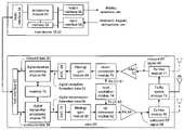
- FIG. 2is a schematic block diagram illustrating a wireless communication device that includes the host device 18 – 32 and an associated radio 60 .
- the radio 60is a built-in component.
- the radio 60may be built-in or an externally coupled component.
- the host device 18 – 32includes a processing module 50 , memory 52 , radio interface 54 , input interface 58 and output interface 56 .
- the processing module 50 and memory 52execute the corresponding instructions that are typically done by the host device. For example, for a cellular telephone host device, the processing module 50 performs the corresponding communication functions in accordance with a particular cellular telephone standard.
- the radio interface 54allows data to be received from and sent to the radio 60 .
- the radio interface 54For data received from the radio 60 (e.g., inbound data), the radio interface 54 provides the data to the processing module 50 for further processing and/or routing to the output interface 56 .
- the output interface 56provides connectivity to an output display device such as a display, monitor, speakers, et cetera such that the received data may be displayed.
- the radio interface 54also provides data from the processing module 50 to the radio 60 .
- the processing module 50may receive the outbound data from an input device such as a keyboard, keypad, microphone, et cetera via the input interface 58 or generate the data itself.
- the processing module 50may perform a corresponding host function on the data and/or route it to the radio 60 via the radio interface 54 .
- Radio 60includes a host interface 62 , digital receiver processing module 64 , an analog-to-digital converter 66 , a filtering/gain module 68 , an IF mixing down conversion stage 70 , a receiver filter 71 , a low noise amplifier 72 , a transmitter/receiver switch 73 , a local oscillation module 74 , memory 75 , a digital transmitter processing module 76 , a digital-to-analog converter 78 , a filtering/gain module 80 , an IF mixing up conversion stage 82 , a power amplifier 84 , a transmitter filter module 85 , and an antenna 86 .
- the antenna 86may be a single antenna that is shared by the transmit and receive paths as regulated by the Tx/Rx switch 73 , or may include separate antennas for the transmit path and receive path.
- the antenna implementationwill depend on the particular standard to which the wireless communication device is compliant.
- the digital receiver processing module 64 and the digital transmitter processing module 76in combination with operational instructions stored in memory 75 , execute digital receiver baseband functions and digital transmitter baseband functions, respectively.
- the digital receiver functionsinclude, but are not limited to, digital intermediate frequency to baseband conversion, demodulation, constellation demapping, decoding, and/or descrambling.
- the digital transmitter functionsinclude, but are not limited to, scrambling, encoding, constellation mapping, modulation, and/or digital baseband to IF conversion.
- the digital receiver and transmitter processing modules 64 and 76may be implemented using a shared processing device, individual processing devices, or a plurality of processing devices.
- Such a processing devicemay be a microprocessor, micro-controller, digital signal processor, microcomputer, central processing unit, field programmable gate array, programmable logic device, state machine, logic circuitry, analog circuitry, digital circuitry, and/or any device that manipulates signals (analog and/or digital) based on operational instructions.
- the memory 75may be a single memory device or a plurality of memory devices.
- Such a memory devicemay be a read-only memory, random access memory, volatile memory, non-volatile memory, static memory, dynamic memory, flash memory, and/or any device that stores digital information.
- the processing module 64 and/or 76implements one or more of its functions via a state machine, analog circuitry, digital circuitry, and/or logic circuitry
- the memory storing the corresponding operational instructionsis embedded with the circuitry comprising the state machine, analog circuitry, digital circuitry, and/or logic circuitry.
- the radio 60receives outbound data 94 from the host device via the host interface 62 .
- the host interface 62routes the outbound data 94 to the digital transmitter processing module 76 , which processes the outbound data 94 in accordance with a particular wireless communication standard (e.g., IEEE 802.11, Bluetooth, et cetera) to produce digital transmission formatted data 96 .
- the digital transmission formatted data 96will be a digital base-band signal or a digital low IF signal, where the low IF typically will be in the frequency range of one hundred kilohertz to a few megahertz. Further, the digital transmission formatted data 96 will be based on the channel width of the RF channel on which the data 96 will ultimately be transmitted.
- the channel widthmay be 10 MHz, 20 MHz, or 40 MHz.
- a 10 MHz wide channelmay include 32 subcarrier frequencies
- a 20 MHz wide channelmay include 64 subcarrier frequencies
- a 40 MHz wide channelmay include 128 subcarrier frequencies, where the number of subcarriers used per channel is at least partially based on the spectral masked configured for the channel. Configuring the spectral mask will be described in greater detail with reference to FIGS. 3–6 .
- the digital-to-analog converter 78converts the digital transmission formatted data 96 from the digital domain to the analog domain.
- the filtering/gain module 80filters and/or adjusts the gain of the analog signal prior to providing it to the IF mixing stage 82 .
- the IF mixing stage 82converts the analog baseband or low IF signal into an RF signal based on a transmitter local oscillation 83 provided by local oscillation module 74 .
- the power amplifier 84amplifies the RF signal to produce outbound RF signal 98 , which is filtered by the transmitter filter module 85 .
- the antenna 86transmits the outbound RF signal 98 to a targeted device such as a base station, an access point and/or another wireless communication device. Note that the bandpass regions of the filters 80 and 85 are dependent upon the configured spectral mask for the RF transmission, which may be determined by the digital transmitter processing module 76 .
- the radio 60also receives an inbound RF signal 88 via the antenna 86 , which was transmitted by a base station, an access point, or another wireless communication device.
- the antenna 86provides the inbound RF signal 88 to the receiver filter module 71 via the Tx/Rx switch 73 , where the Rx filter 71 bandpass filters the inbound RF signal 88 .
- the Rx filter 71provides the filtered RF signal to low noise amplifier 72 , which amplifies the signal 88 to produce an amplified inbound RF signal.
- the low noise amplifier 72provides the amplified inbound RF signal to the IF mixing module 70 , which directly converts the amplified inbound RF signal into an inbound low IF signal or baseband signal based on a receiver local oscillation 81 provided by local oscillation module 74 .
- the down conversion module 70provides the inbound low IF signal or baseband signal to the filtering/gain module 68 .
- the filtering/gain module 68filters and/or gains the inbound low IF signal or the inbound baseband signal to produce a filtered inbound signal. Note that the bandpass regions of the filters 71 and 68 are dependent upon the configured spectral mask for the RF transmission, which may be determined by the receiver processing module 64 .
- the analog-to-digital converter 66converts the filtered inbound signal from the analog domain to the digital domain to produce digital reception formatted data 90 .
- the digital receiver processing module 64decodes, descrambles, demaps, and/or demodulates the digital reception formatted data 90 to recapture inbound data 92 in accordance with the particular wireless communication standard being implemented by radio 60 and the particular channel width of the channel.
- the host interface 62provides the recaptured inbound data 92 to the host device 18 – 32 via the radio interface 54 .
- the wireless communication device of FIG. 2may be implemented using one or more integrated circuits.
- the host devicemay be implemented on one integrated circuit
- the digital receiver processing module 64the digital transmitter processing module 76 and memory 75 may be implemented on a second integrated circuit
- the remaining components of the radio 60less the antenna 86
- the radio 60may be implemented on a single integrated circuit.
- the processing module 50 of the host device and the digital receiver and transmitter processing modules 64 and 76may be a common processing device implemented on a single integrated circuit.
- the memory 52 and memory 75may be implemented on a single integrated circuit and/or on the same integrated circuit as the common processing modules of processing module 50 and the digital receiver and transmitter processing module 64 and 76 .
- FIG. 3is a diagram depicting a plurality of frequency bands (e.g., frequency band 1 through frequency band N), which are defined by a governmental agency for particular wireless applications.
- FCCFederal Communications Commission
- the Federal Communications Commissiondefines, for the United States, frequency bands for specific uses and for which an FCC license is required (e.g., radio transmissions, television transmissions, etc.) and also defines frequency bands that are unlicensed and, as such, can be used for a variety of applications.
- the FCChas defined several frequency bands in the radio frequency spectrum as being unlicensed.
- Such unlicensed frequency bandsinclude 902–928 MHz, 2.4–2.483 GHz and 5.75–5.85 GHz, which are collectively referred to as the ISM (Industrial Scientific Medical) band.
- ISMIntelligent Scientific Medical
- the ISM bandis used for in-building and system applications (e.g., bar code readers), industrial microwave ovens, wireless patient monitors, and wireless local area networks (WLAN).
- WLANwireless local area networks
- the frequency bands of FIG. 3include, but are not limited to, 2.400–2.4835 GHz, 2.471–2.497 GHz, 5.15–5.25 GHz, 5.25–5.35 GHz, 5.47–5.725 GHz, 5.725 GHz–5.825 GHz, 4.9–5.3 GHz, and 5.85–5.925 GHz.
- FIG. 4is a diagram depicting a particular frequency band that is divided into a plurality of channels.
- the channel width of each channelis selectable. As such, for a given frequency band, the number of channels will vary depending on the selected channel width. For instance, in one embodiment of the present invention, the channel width may be selected in accordance with IEEE 802.11 (a) or (g), where IEEE 802.11 (a) provides wireless LAN operation specifications in the 5.15 to 5.35 GHz band.
- the specified modulation schemesare based on Orthogonal Frequency Division Multiplexing (OFDM) which, for 802.11(a) divides the 5.15 to 5.35 GHz band into eight 20 MHz wide channels centered at 5.18, 5.20, 5.22, 5.24, 5.26, 5.28, 5.30, and 5.32 GHz.
- OFDMOrthogonal Frequency Division Multiplexing
- the 5.15 to 5.35 GHz bandmay be divided into eighteen 10 MHz wide channels, with the first channel centered at 5.165 GHz and the remaining eleven centered at 10 MHz increments therefrom.
- the 5.15 to 5.35 GHz bandmay be dividing into four 40 MHz wide channels, with the channels centered at 5.21, 5.25, 5.29, and 5.33 GHz.
- the same channel width selectivitymay be applied to the 2.4–2.4835 GHz band covered by IEEE 802.11 (g), other frequency bands covered by an IEEE 802.11 standard, and/or any other wireless communication standard.
- the selectivity of the channel widthprovides for greater data throughput (e.g., at least twice the data rate of IEEE 802.11 (g)), for a diversity of applications, and/or for a single wireless communication device to support multiple wireless standards issued by various standard bodies, including governmental agencies.
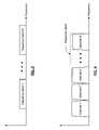
- FIG. 5is a diagram of a configurable spectral mask 100 that includes a channel pass region 102 , a transition region 104 , and a floor region 106 .
- the transition region 104includes a first attenuation region 108 , a second attenuation region 110 , and a third attenuation region 112 .
- Such a spectral mask 100promotes interoperability, coexistence, and system capacity by limiting interference to adjacent and other channels for a wide variety of applications and/or standards.
- the out of band maske.g., the transition region 104 and the floor region 106 ) places a lower bound on interference levels that can be expected in receivers regardless of their particular implementation. In an effort to minimize the interference energy that appears on top of the desired signal, the out of band regions are made as small as possible.
- the channel pass region 102which encompasses the desired signal, is of a value as close to the channel bandwidth as feasible.
- the transition region 104which bounds the adjacent channel interference and is limited by the bandwidth of the baseband processing modules 64 and 76 and the intermediate frequency mixing stage of the up-conversion module 82 , is selected to minimize such interference (i.e., post IF inter-modulation distortion (IMD)).
- the floor region 106which bounds other channel interference, which is outside the range of the filters and IMD limits and is generally limited by the local oscillation 74 phase noise, is selected based on achievable phase noise levels.
- the transition region 104should have a roll off based on the shoulder height of IMD, which may be assumed to be produced by a 3 rd order compressive non-linearity.
- the distorted signal bandwidthwill be no greater than three times the ideal signal bandwidth.
- FIG. 6is a table illustrating a few examples of values for a configurable spectral mask 100 . While the table includes channel widths of 10, 20, and 40 MHz, one of average skill in the art will appreciate, other channel widths may be used. Further, the transition region may include more or less attenuation regions than the three shown in FIG. 5 .
- the term “substantially” or “approximately”, as may be used herein,provides an industry-accepted tolerance to its corresponding term. Such an industry-accepted tolerance ranges from less than one percent to twenty percent and corresponds to, but is not limited to, component values, integrated circuit process variations, temperature variations, rise and fall times, and/or thermal noise.
- the term “operably coupled”, as may be used herein,includes direct coupling and indirect coupling via another component, element, circuit, or module where, for indirect coupling, the intervening component, element, circuit, or module does not modify the information of a signal but may adjust its current level, voltage level, and/or power level.
- inferred couplingincludes direct and indirect coupling between two elements in the same manner as “operably coupled”.
- the term “compares favorably”, as may be used herein,indicates that a comparison between two or more elements, items, signals, etc., provides a desired relationship. For example, when the desired relationship is that signal 1 has a greater magnitude than signal 2 , a favorable comparison may be achieved when the magnitude of signal 1 is greater than that of signal 2 or when the magnitude of signal 2 is less than that of signal 1 .
Landscapes
- Engineering & Computer Science (AREA)
- Signal Processing (AREA)
- Computer Networks & Wireless Communication (AREA)
- Mobile Radio Communication Systems (AREA)
Abstract
Description
Claims (24)
Priority Applications (12)
| Application Number | Priority Date | Filing Date | Title |
|---|---|---|---|
| US10/778,754US7162204B2 (en) | 2003-11-24 | 2004-02-13 | Configurable spectral mask for use in a high data throughput wireless communication |
| EP04008792AEP1533910B1 (en) | 2003-11-24 | 2004-04-13 | Configurable spectral mask for use in a high data throughput wireless communication |
| EP04017018AEP1501251A3 (en) | 2003-07-18 | 2004-07-19 | Frame structure for multicarrier transmission |
| TW93121533ATWI261429B (en) | 2003-07-18 | 2004-07-19 | A method for generating OFDM frame for wireless communications |
| CNB2004100695740ACN100502376C (en) | 2003-07-18 | 2004-07-19 | Device and method for generating OFDM frames in wireless communication |
| US10/973,611US7751429B2 (en) | 2004-02-13 | 2004-10-26 | Signaling format for WLANS |
| US10/973,612US7400643B2 (en) | 2004-02-13 | 2004-10-26 | Transmission of wide bandwidth signals in a network having legacy devices |
| US11/056,155US7590189B2 (en) | 2004-02-13 | 2005-02-14 | Signaling format for wireless communications |
| US11/825,868US8406204B2 (en) | 2004-02-13 | 2007-07-10 | Transmission of wide bandwidth signals in a network having legacy devices |
| US12/559,824US8094749B2 (en) | 2004-02-13 | 2009-09-15 | Signaling format for wireless communications |
| US13/316,753US8630367B2 (en) | 2004-02-13 | 2011-12-12 | Signaling format for wireless communications |
| US13/622,718US8929317B2 (en) | 2004-02-13 | 2012-09-19 | Transmission of wide bandwidth signals in a network having legacy devices |
Applications Claiming Priority (2)
| Application Number | Priority Date | Filing Date | Title |
|---|---|---|---|
| US52452803P | 2003-11-24 | 2003-11-24 | |
| US10/778,754US7162204B2 (en) | 2003-11-24 | 2004-02-13 | Configurable spectral mask for use in a high data throughput wireless communication |
Related Parent Applications (1)
| Application Number | Title | Priority Date | Filing Date |
|---|---|---|---|
| US10/778,751Continuation-In-PartUS7269430B2 (en) | 2003-11-24 | 2004-02-13 | Frame format for high data throughput wireless local area network transmissions |
Related Child Applications (5)
| Application Number | Title | Priority Date | Filing Date |
|---|---|---|---|
| US10/779,245Continuation-In-PartUS7539501B2 (en) | 2003-11-24 | 2004-02-13 | High data throughput wireless local area network receiver |
| US10/778,751Continuation-In-PartUS7269430B2 (en) | 2003-11-24 | 2004-02-13 | Frame format for high data throughput wireless local area network transmissions |
| US10/973,611Continuation-In-PartUS7751429B2 (en) | 2004-02-13 | 2004-10-26 | Signaling format for WLANS |
| US10/973,612Continuation-In-PartUS7400643B2 (en) | 2004-02-13 | 2004-10-26 | Transmission of wide bandwidth signals in a network having legacy devices |
| US11/056,155Continuation-In-PartUS7590189B2 (en) | 2004-02-13 | 2005-02-14 | Signaling format for wireless communications |
Publications (2)
| Publication Number | Publication Date |
|---|---|
| US20050113101A1 US20050113101A1 (en) | 2005-05-26 |
| US7162204B2true US7162204B2 (en) | 2007-01-09 |
Family
ID=34437384
Family Applications (1)
| Application Number | Title | Priority Date | Filing Date |
|---|---|---|---|
| US10/778,754Expired - LifetimeUS7162204B2 (en) | 2003-07-18 | 2004-02-13 | Configurable spectral mask for use in a high data throughput wireless communication |
Country Status (2)
| Country | Link |
|---|---|
| US (1) | US7162204B2 (en) |
| EP (1) | EP1533910B1 (en) |
Cited By (21)
| Publication number | Priority date | Publication date | Assignee | Title |
|---|---|---|---|---|
| US20060030267A1 (en)* | 2004-03-29 | 2006-02-09 | Engim, Inc. | Detecting and eliminating spurious energy in communications systems via multi-channel processing |
| US20090081970A1 (en)* | 2007-09-21 | 2009-03-26 | Qualcomm Incorporated | Interference management employing fractional frequency reuse |
| US20090080386A1 (en)* | 2007-09-21 | 2009-03-26 | Qualcomm Incorporated | Interference management employing fractional time reuse |
| US20090082026A1 (en)* | 2007-09-21 | 2009-03-26 | Qualcomm Incorporated | Interference management utilizing power control |
| US20090080499A1 (en)* | 2007-09-21 | 2009-03-26 | Qualcomm Incorporated | Interference management employing fractional code reuse |
| US20090082027A1 (en)* | 2007-09-21 | 2009-03-26 | Qualcomm Incorporated | Interference management utilizing harq interlaces |
| US20090086861A1 (en)* | 2007-09-21 | 2009-04-02 | Qualcomm Incorporated | Interference management utilizing power and attenuation profiles |
| US20090135796A1 (en)* | 2007-11-27 | 2009-05-28 | Qualcomm Incorporated | Interface management in a wireless communication system using subframe time reuse |
| US20090252099A1 (en)* | 2007-11-27 | 2009-10-08 | Qualcomm Incorporated | Interference management in a wireless communication system using frequency selective transmission |
| US20090323600A1 (en)* | 2008-06-27 | 2009-12-31 | Microsoft Corporation | Adapting channel width for improving the performance of wireless networks |
| US20100002672A1 (en)* | 2004-02-13 | 2010-01-07 | Broadcom Corporation | Signaling format for wireless communications |
| US20100304678A1 (en)* | 2009-05-28 | 2010-12-02 | Microsoft Corporation | Spectrum Assignment for Networks Over White Spaces and Other Portions of the Spectrum |
| US20110035522A1 (en)* | 2009-08-04 | 2011-02-10 | Microsoft Corporation | Software-Defined Radio Using Multi-Core Processor |
| US8627189B2 (en) | 2009-12-03 | 2014-01-07 | Microsoft Corporation | High performance digital signal processing in software radios |
| US8929933B2 (en) | 2011-05-04 | 2015-01-06 | Microsoft Corporation | Spectrum allocation for base station |
| US8989286B2 (en) | 2011-11-10 | 2015-03-24 | Microsoft Corporation | Mapping a transmission stream in a virtual baseband to a physical baseband with equalization |
| US9065584B2 (en) | 2010-09-29 | 2015-06-23 | Qualcomm Incorporated | Method and apparatus for adjusting rise-over-thermal threshold |
| US9130711B2 (en) | 2011-11-10 | 2015-09-08 | Microsoft Technology Licensing, Llc | Mapping signals from a virtual frequency band to physical frequency bands |
| US9753884B2 (en) | 2009-09-30 | 2017-09-05 | Microsoft Technology Licensing, Llc | Radio-control board for software-defined radio platform |
| US20220141615A1 (en)* | 2007-09-10 | 2022-05-05 | Theodore S. Rappaport | Clearinghouse System and Method for Enhancing the Quality, Operation and Accessibility of Carrier-Based Networks |
| US11991101B2 (en) | 2018-09-04 | 2024-05-21 | Huawei Technologies Co., Ltd. | Using enhanced signal spectral TX mask for improved multi-user grouping and increased spectral efficiency |
Families Citing this family (8)
| Publication number | Priority date | Publication date | Assignee | Title |
|---|---|---|---|---|
| EP1881662A1 (en) | 2006-07-18 | 2008-01-23 | Siemens Aktiengesellschaft | Filter adjustment depending on the occupancy of the neighbouring band |
| US8243612B2 (en)* | 2007-08-01 | 2012-08-14 | Microsoft Corporation | Dynamic channel-width allocation in wireless networks |
| RU2499367C2 (en)* | 2007-09-21 | 2013-11-20 | Квэлкомм Инкорпорейтед | Interference management employing fractional time reuse |
| EP2232724B1 (en)* | 2008-01-18 | 2014-10-15 | Telefonaktiebolaget LM Ericsson (publ) | A method and a device for improved scheduling |
| KR101441500B1 (en) | 2008-06-20 | 2014-11-04 | 삼성전자주식회사 | Apparatus and method for transmitting a sounding reference signal in an uplink wireless communication system using multiple antennas and sounding reference signal hopping |
| CN102687476B (en)* | 2009-06-26 | 2017-06-30 | 普拉斯N有限责任公司 | Systems and methods for controlling combined wireless signals |
| GB2499147B (en) | 2010-10-28 | 2015-06-03 | Ibm | Microfluidic device with auxiliary and bypass channels |
| US10903873B2 (en)* | 2017-10-23 | 2021-01-26 | Mediatek Inc. | Wireless communication method and associated wireless device |
Citations (8)
| Publication number | Priority date | Publication date | Assignee | Title |
|---|---|---|---|---|
| US6563880B1 (en)* | 1994-07-12 | 2003-05-13 | Ibiquity Digital Corporation | Method and system for simultaneously broadcasting and receiving digital and analog signals |
| US20040234001A1 (en)* | 2001-06-20 | 2004-11-25 | Huynh Thien Luong | Adaptive radio frequency (rf) filter |
| US20040266372A1 (en)* | 2003-06-30 | 2004-12-30 | Mccallister Ronald D. | Methods and apparatus for controlling signals |
| US20050070231A1 (en)* | 2003-09-30 | 2005-03-31 | Jensen Henrik T. | Technique for improving modulation performance of translational loop RF transmitters |
| US20050111449A1 (en)* | 2003-11-24 | 2005-05-26 | Tushar Moorti | High data throughput wireless local area network receiver |
| US6940913B2 (en)* | 2000-04-04 | 2005-09-06 | Tioga Technologies, Inc. | Communication start-up with variant spectral density mask |
| US20060030267A1 (en)* | 2004-03-29 | 2006-02-09 | Engim, Inc. | Detecting and eliminating spurious energy in communications systems via multi-channel processing |
| US7031690B2 (en)* | 2002-03-29 | 2006-04-18 | Agere Systems Inc. | Polyphase filter with low-pass response |
- 2004
- 2004-02-13USUS10/778,754patent/US7162204B2/ennot_activeExpired - Lifetime
- 2004-04-13EPEP04008792Apatent/EP1533910B1/ennot_activeExpired - Lifetime
Patent Citations (8)
| Publication number | Priority date | Publication date | Assignee | Title |
|---|---|---|---|---|
| US6563880B1 (en)* | 1994-07-12 | 2003-05-13 | Ibiquity Digital Corporation | Method and system for simultaneously broadcasting and receiving digital and analog signals |
| US6940913B2 (en)* | 2000-04-04 | 2005-09-06 | Tioga Technologies, Inc. | Communication start-up with variant spectral density mask |
| US20040234001A1 (en)* | 2001-06-20 | 2004-11-25 | Huynh Thien Luong | Adaptive radio frequency (rf) filter |
| US7031690B2 (en)* | 2002-03-29 | 2006-04-18 | Agere Systems Inc. | Polyphase filter with low-pass response |
| US20040266372A1 (en)* | 2003-06-30 | 2004-12-30 | Mccallister Ronald D. | Methods and apparatus for controlling signals |
| US20050070231A1 (en)* | 2003-09-30 | 2005-03-31 | Jensen Henrik T. | Technique for improving modulation performance of translational loop RF transmitters |
| US20050111449A1 (en)* | 2003-11-24 | 2005-05-26 | Tushar Moorti | High data throughput wireless local area network receiver |
| US20060030267A1 (en)* | 2004-03-29 | 2006-02-09 | Engim, Inc. | Detecting and eliminating spurious energy in communications systems via multi-channel processing |
Cited By (48)
| Publication number | Priority date | Publication date | Assignee | Title |
|---|---|---|---|---|
| US8094749B2 (en) | 2004-02-13 | 2012-01-10 | Broadcom Corporation | Signaling format for wireless communications |
| US8630367B2 (en) | 2004-02-13 | 2014-01-14 | Broadcom Corporation | Signaling format for wireless communications |
| US20100002672A1 (en)* | 2004-02-13 | 2010-01-07 | Broadcom Corporation | Signaling format for wireless communications |
| US7835701B2 (en)* | 2004-03-29 | 2010-11-16 | Edgewater Computer Systems, Inc. | Detecting and eliminating spurious energy in communications systems via multi-channel processing |
| US20060030267A1 (en)* | 2004-03-29 | 2006-02-09 | Engim, Inc. | Detecting and eliminating spurious energy in communications systems via multi-channel processing |
| US20220141615A1 (en)* | 2007-09-10 | 2022-05-05 | Theodore S. Rappaport | Clearinghouse System and Method for Enhancing the Quality, Operation and Accessibility of Carrier-Based Networks |
| US20090082027A1 (en)* | 2007-09-21 | 2009-03-26 | Qualcomm Incorporated | Interference management utilizing harq interlaces |
| US9066306B2 (en) | 2007-09-21 | 2015-06-23 | Qualcomm Incorporated | Interference management utilizing power control |
| US9374791B2 (en) | 2007-09-21 | 2016-06-21 | Qualcomm Incorporated | Interference management utilizing power and attenuation profiles |
| US9344973B2 (en) | 2007-09-21 | 2016-05-17 | Qualcomm Incorporated | Interference management utilizing power and attenuation profiles |
| US9137806B2 (en) | 2007-09-21 | 2015-09-15 | Qualcomm Incorporated | Interference management employing fractional time reuse |
| US9078269B2 (en) | 2007-09-21 | 2015-07-07 | Qualcomm Incorporated | Interference management utilizing HARQ interlaces |
| TWI413422B (en)* | 2007-09-21 | 2013-10-21 | Qualcomm Inc | Interference management using fractional frequency reuse |
| US20090086861A1 (en)* | 2007-09-21 | 2009-04-02 | Qualcomm Incorporated | Interference management utilizing power and attenuation profiles |
| US20090080499A1 (en)* | 2007-09-21 | 2009-03-26 | Qualcomm Incorporated | Interference management employing fractional code reuse |
| US20090082026A1 (en)* | 2007-09-21 | 2009-03-26 | Qualcomm Incorporated | Interference management utilizing power control |
| US8824979B2 (en)* | 2007-09-21 | 2014-09-02 | Qualcomm Incorporated | Interference management employing fractional frequency reuse |
| US20090080386A1 (en)* | 2007-09-21 | 2009-03-26 | Qualcomm Incorporated | Interference management employing fractional time reuse |
| US20090081970A1 (en)* | 2007-09-21 | 2009-03-26 | Qualcomm Incorporated | Interference management employing fractional frequency reuse |
| AU2008302066B2 (en)* | 2007-09-21 | 2012-11-29 | Qualcomm Incorporated | Interference management employing fractional frequency reuse |
| US20090252099A1 (en)* | 2007-11-27 | 2009-10-08 | Qualcomm Incorporated | Interference management in a wireless communication system using frequency selective transmission |
| US20090137221A1 (en)* | 2007-11-27 | 2009-05-28 | Qualcomm Incorporated | Interference management in a wireless communication system using beam and null steering |
| US20090135796A1 (en)* | 2007-11-27 | 2009-05-28 | Qualcomm Incorporated | Interface management in a wireless communication system using subframe time reuse |
| US20090137241A1 (en)* | 2007-11-27 | 2009-05-28 | Qualcomm Incorporated | Interference management in a wireless communication system using adaptive path loss adjustment |
| US20090135790A1 (en)* | 2007-11-27 | 2009-05-28 | Qualcomm Incorporated | Interface management in wireless communication system using hybrid time reuse |
| US9288814B2 (en) | 2007-11-27 | 2016-03-15 | Qualcomm Incorporated | Interface management in wireless communication system using hybrid time reuse |
| US9119217B2 (en) | 2007-11-27 | 2015-08-25 | Qualcomm Incorporated | Interference management in a wireless communication system using frequency selective transmission |
| US8837305B2 (en) | 2007-11-27 | 2014-09-16 | Qualcomm Incorporated | Interference management in a wireless communication system using beam and null steering |
| US8848619B2 (en) | 2007-11-27 | 2014-09-30 | Qualcomm Incorporated | Interface management in a wireless communication system using subframe time reuse |
| US8867456B2 (en) | 2007-11-27 | 2014-10-21 | Qualcomm Incorporated | Interface management in wireless communication system using hybrid time reuse |
| US20090135754A1 (en)* | 2007-11-27 | 2009-05-28 | Qualcomm Incorporated | Interference management in a wireless communication system using overhead channel power control |
| US8948095B2 (en) | 2007-11-27 | 2015-02-03 | Qualcomm Incorporated | Interference management in a wireless communication system using frequency selective transmission |
| US9072102B2 (en) | 2007-11-27 | 2015-06-30 | Qualcomm Incorporated | Interference management in a wireless communication system using adaptive path loss adjustment |
| US20090323600A1 (en)* | 2008-06-27 | 2009-12-31 | Microsoft Corporation | Adapting channel width for improving the performance of wireless networks |
| US8699424B2 (en) | 2008-06-27 | 2014-04-15 | Microsoft Corporation | Adapting channel width for improving the performance of wireless networks |
| US8811903B2 (en) | 2009-05-28 | 2014-08-19 | Microsoft Corporation | Spectrum assignment for networks over white spaces and other portions of the spectrum |
| US9730186B2 (en) | 2009-05-28 | 2017-08-08 | Microsoft Technology Licensing, Llc | Spectrum assignment for networks over white spaces and other portions of the spectrum |
| US20100304678A1 (en)* | 2009-05-28 | 2010-12-02 | Microsoft Corporation | Spectrum Assignment for Networks Over White Spaces and Other Portions of the Spectrum |
| US20110035522A1 (en)* | 2009-08-04 | 2011-02-10 | Microsoft Corporation | Software-Defined Radio Using Multi-Core Processor |
| US8565811B2 (en) | 2009-08-04 | 2013-10-22 | Microsoft Corporation | Software-defined radio using multi-core processor |
| US9753884B2 (en) | 2009-09-30 | 2017-09-05 | Microsoft Technology Licensing, Llc | Radio-control board for software-defined radio platform |
| US8627189B2 (en) | 2009-12-03 | 2014-01-07 | Microsoft Corporation | High performance digital signal processing in software radios |
| US9065584B2 (en) | 2010-09-29 | 2015-06-23 | Qualcomm Incorporated | Method and apparatus for adjusting rise-over-thermal threshold |
| US8929933B2 (en) | 2011-05-04 | 2015-01-06 | Microsoft Corporation | Spectrum allocation for base station |
| US9918313B2 (en) | 2011-05-04 | 2018-03-13 | Microsoft Technology Licensing, Llc | Spectrum allocation for base station |
| US9130711B2 (en) | 2011-11-10 | 2015-09-08 | Microsoft Technology Licensing, Llc | Mapping signals from a virtual frequency band to physical frequency bands |
| US8989286B2 (en) | 2011-11-10 | 2015-03-24 | Microsoft Corporation | Mapping a transmission stream in a virtual baseband to a physical baseband with equalization |
| US11991101B2 (en) | 2018-09-04 | 2024-05-21 | Huawei Technologies Co., Ltd. | Using enhanced signal spectral TX mask for improved multi-user grouping and increased spectral efficiency |
Also Published As
| Publication number | Publication date |
|---|---|
| EP1533910A3 (en) | 2007-04-04 |
| US20050113101A1 (en) | 2005-05-26 |
| EP1533910A2 (en) | 2005-05-25 |
| EP1533910B1 (en) | 2012-03-21 |
Similar Documents
| Publication | Publication Date | Title |
|---|---|---|
| US7162204B2 (en) | Configurable spectral mask for use in a high data throughput wireless communication | |
| US9247439B2 (en) | High data throughput wireless local area network receiver | |
| EP1708372B1 (en) | Multiple band direct conversion radio frequency transceiver integrated circuit | |
| EP1708371B1 (en) | Multiple band multiple input multiple output transceiver integrated circuit | |
| US9634716B2 (en) | Enhanced granularity operational parameters adjustment of components and modules in a multi-band, multi-standard communication device | |
| CN103905010B (en) | The method of adjustment of semiconductor device and filter circuit | |
| US20050113026A1 (en) | Frame format for high data throughput wireless local area network transmissions | |
| US7092679B2 (en) | Low loss diversity antenna T/R switch | |
| US6859646B2 (en) | Signal gain adjustment within an RF integrated circuit | |
| US7181187B2 (en) | RF transmitter having improved out of band attenuation | |
| US7310386B2 (en) | Radio receiver utilizing a single analog to digital converter | |
| US8107442B2 (en) | Master/slave oscillation production and distribution in a multiple RF transceiver system supporting MIMO operations | |
| US20060066431A1 (en) | Adjustable differential inductor | |
| US7676201B2 (en) | Selectable sideband transmission | |
| US7457380B2 (en) | Low noise circuit and applications thereof | |
| HK1180465A1 (en) | Transmitter front end with programmable notch filter and methods for use therewith | |
| HK1180465B (en) | Transmitter front end with programmable notch filter and methods for use therewith |
Legal Events
| Date | Code | Title | Description |
|---|---|---|---|
| AS | Assignment | Owner name:BROADCOM CORPORATION, CALIFORNIA Free format text:ASSIGNMENT OF ASSIGNORS INTEREST;ASSIGNORS:HANSEN, CHRISTOPHER J.;MOORTI, R. TUSHAR;TRACHOWSKY, JASON A.;REEL/FRAME:014991/0812 Effective date:20040211 | |
| STCF | Information on status: patent grant | Free format text:PATENTED CASE | |
| CC | Certificate of correction | ||
| FPAY | Fee payment | Year of fee payment:4 | |
| CC | Certificate of correction | ||
| FPAY | Fee payment | Year of fee payment:8 | |
| SULP | Surcharge for late payment | Year of fee payment:7 | |
| AS | Assignment | Owner name:BANK OF AMERICA, N.A., AS COLLATERAL AGENT, NORTH CAROLINA Free format text:PATENT SECURITY AGREEMENT;ASSIGNOR:BROADCOM CORPORATION;REEL/FRAME:037806/0001 Effective date:20160201 Owner name:BANK OF AMERICA, N.A., AS COLLATERAL AGENT, NORTH Free format text:PATENT SECURITY AGREEMENT;ASSIGNOR:BROADCOM CORPORATION;REEL/FRAME:037806/0001 Effective date:20160201 | |
| AS | Assignment | Owner name:AVAGO TECHNOLOGIES GENERAL IP (SINGAPORE) PTE. LTD., SINGAPORE Free format text:ASSIGNMENT OF ASSIGNORS INTEREST;ASSIGNOR:BROADCOM CORPORATION;REEL/FRAME:041706/0001 Effective date:20170120 Owner name:AVAGO TECHNOLOGIES GENERAL IP (SINGAPORE) PTE. LTD Free format text:ASSIGNMENT OF ASSIGNORS INTEREST;ASSIGNOR:BROADCOM CORPORATION;REEL/FRAME:041706/0001 Effective date:20170120 | |
| AS | Assignment | Owner name:BROADCOM CORPORATION, CALIFORNIA Free format text:TERMINATION AND RELEASE OF SECURITY INTEREST IN PATENTS;ASSIGNOR:BANK OF AMERICA, N.A., AS COLLATERAL AGENT;REEL/FRAME:041712/0001 Effective date:20170119 | |
| MAFP | Maintenance fee payment | Free format text:PAYMENT OF MAINTENANCE FEE, 12TH YEAR, LARGE ENTITY (ORIGINAL EVENT CODE: M1553) Year of fee payment:12 | |
| AS | Assignment | Owner name:AVAGO TECHNOLOGIES INTERNATIONAL SALES PTE. LIMITE Free format text:MERGER;ASSIGNOR:AVAGO TECHNOLOGIES GENERAL IP (SINGAPORE) PTE. LTD.;REEL/FRAME:047196/0097 Effective date:20180509 | |
| AS | Assignment | Owner name:AVAGO TECHNOLOGIES INTERNATIONAL SALES PTE. LIMITE Free format text:CORRECTIVE ASSIGNMENT TO CORRECT THE EXECUTION DATE PREVIOUSLY RECORDED AT REEL: 047196 FRAME: 0097. ASSIGNOR(S) HEREBY CONFIRMS THE MERGER;ASSIGNOR:AVAGO TECHNOLOGIES GENERAL IP (SINGAPORE) PTE. LTD.;REEL/FRAME:048555/0510 Effective date:20180905 |