US7161729B2 - Array of micromirror array lenses - Google Patents
Array of micromirror array lensesDownload PDFInfo
- Publication number
- US7161729B2 US7161729B2US10/857,714US85771404AUS7161729B2US 7161729 B2US7161729 B2US 7161729B2US 85771404 AUS85771404 AUS 85771404AUS 7161729 B2US7161729 B2US 7161729B2
- Authority
- US
- United States
- Prior art keywords
- lens
- micromirrors
- micromirror
- lens array
- array
- Prior art date
- Legal status (The legal status is an assumption and is not a legal conclusion. Google has not performed a legal analysis and makes no representation as to the accuracy of the status listed.)
- Expired - Lifetime
Links
- 230000003287optical effectEffects0.000claimsabstractdescription22
- 230000004075alterationEffects0.000claimsabstractdescription14
- 238000004377microelectronicMethods0.000claimsabstractdescription9
- 238000005516engineering processMethods0.000claimsabstractdescription6
- 230000008859changeEffects0.000claimsabstractdescription5
- 238000013519translationMethods0.000claimsdescription31
- 238000003384imaging methodMethods0.000claimsdescription16
- 230000003044adaptive effectEffects0.000claimsdescription8
- 238000002310reflectometryMethods0.000claimsdescription6
- 239000000463materialSubstances0.000claimsdescription5
- 230000007547defectEffects0.000claimsdescription4
- 239000002184metalSubstances0.000claimsdescription4
- 238000004519manufacturing processMethods0.000claimsdescription2
- 230000014616translationEffects0.000description30
- 238000010586diagramMethods0.000description10
- 230000004044responseEffects0.000description7
- 238000000034methodMethods0.000description6
- 239000004973liquid crystal related substanceSubstances0.000description3
- 230000007246mechanismEffects0.000description3
- 230000008569processEffects0.000description3
- 238000013461designMethods0.000description2
- 238000006073displacement reactionMethods0.000description2
- 150000002736metal compoundsChemical class0.000description2
- 230000001360synchronised effectEffects0.000description2
- 238000003491arrayMethods0.000description1
- 238000012937correctionMethods0.000description1
- 230000010354integrationEffects0.000description1
- 239000007788liquidSubstances0.000description1
- 239000000203mixtureSubstances0.000description1
- 230000000737periodic effectEffects0.000description1
- 238000012545processingMethods0.000description1
Images


Classifications
- G—PHYSICS
- G02—OPTICS
- G02B—OPTICAL ELEMENTS, SYSTEMS OR APPARATUS
- G02B26/00—Optical devices or arrangements for the control of light using movable or deformable optical elements
- G02B26/08—Optical devices or arrangements for the control of light using movable or deformable optical elements for controlling the direction of light
- G02B26/0816—Optical devices or arrangements for the control of light using movable or deformable optical elements for controlling the direction of light by means of one or more reflecting elements
- G02B26/0833—Optical devices or arrangements for the control of light using movable or deformable optical elements for controlling the direction of light by means of one or more reflecting elements the reflecting element being a micromechanical device, e.g. a MEMS mirror, DMD
Definitions
- the present inventionrelates to an array of micromirror array lenses and operational methods for the lens.
- variable focal length lensA most widely used conventional variable focal length system is the one using two refractive lenses. It has complex driving mechanisms to control the relative positions of refractive lenses and a slow response time.
- variable focal length lenseshave been made. Variable focal length lenses can be made by changing the shape of the lens, as is found in the human eye; this method has been used in lenses made with isotropic liquids.
- Other lenseshave been made of electrically variable refractive index media to create either a conventional lens or a gradient index lens by means of a voltage gradient. The electrically variable refractive index allows the focal length of the lenses to be voltage controlled.
- the most advanced variable focal length lensis a liquid crystal variable focal length lens, which has a complex mechanism to control the focal length.
- the micromirror array lensmainly consists of micromirrors and actuating components, and uses a much simpler mechanism to control the focusing system than a liquid crystal variable focal length lens.
- the focal length of the micromirror array lensis varied with the displacement of each micromirror.
- This inventionprovides an array of the micromirror array lens and improves the design and control of the micromirror array lens. It extends advantages and applications of a conventional lens array.
- the present inventioncontrives to solve the disadvantages of an array comprising the conventional variable focal length lens.
- the objective of the inventionis to provide the array comprising variable focal length lenses with high-speed focal length change.
- Another objective of the inventionis to provide the array comprising variable focal length lenses with a function of aberration correction.
- Still another objective of the inventionis to provide the array comprising variable focal length lenses with variable optical axis.
- Still another objective of the inventionis to provide the array comprising variable focal length lenses with arbitrary size and/or type. It extends advantages and applications of a conventional lens array.
- the inventionconsists of many micromirror array lenses, which consists of many micromirrors to reflect the light and actuating components to control positions of the micromirrors.
- each micromirrorhas the same function as a mirror. Therefore, the reflective surface of the micromirror is made of metal, metal compound, or other materials that have high reflectivity. Many known microfabrication processes can make the surface of the micromirror to have high reflectivity.
- the micromirror arrayworks as a reflective focal length lens. In order to do this, the micromirrors are electrostatically and/or electromagnetically controlled to have desired positions by actuating components. The focal length of the lens is changed by controlling translation, by controlling rotation, or by controlling both translation and rotation of each micromirror.
- the micromirror array lens formed by the control of only rotationhas relatively larger aberration than the lens with both translation and rotation since the phase is not controlled by translation.
- the micromirror array lens formed by the control of only translationalso has relatively larger aberration.
- the micromirror array lens with pure translationthe smaller the sizes of the micromirrors are, the less is the aberration. Even though the quality of the lens formed by control of either only translation or only rotation is lower than the lens formed by control of both rotation and translation, it can be used as a low quality lens because its structure and control is much simpler than the lens formed by control of both rotation and translation.
- the micromirror array lenscan be formed by a polar array of the micromirrors.
- each micromirrorhas a fan shape to increase an effective reflective area, so that the optical efficiency increases.
- the aberration of the micromirror array lenscan be reduced by micromirrors with curvatures.
- the optical efficiency of the micromirror array lenscan be improved by locating a mechanical structure upholding micromirrors and the actuating components under micromirrors to increase an effective reflective area. Electric circuits to operate the micromirrors can be replaced with known microelectronics such as MOS or CMOS.
- the effective reflective areacan be increased by removing necessary area for electrode pads and wires.
- the lenscan correct aberration, which is caused by optical effects due to the medium between the object and its image or is caused by defects of a lens system that cause its image to deviate from the rules of paraxial imagery, by controlling each micromirror independently. Independent control of each micromirror is also possible by replacing electric circuits required for control with known microelectronics technologies and fabricating the ciruits underneath the micromirrors using known microfabrication methods.
- the array comprising micromirrors with two degree of freedom rotations or two degree of freedom rotations and one degree of freedom translation which are controlled independentlycan make a lens with arbitrary shape and/or size as desired, or a lens array comprising lenses with arbitrary shape and/or size, as desired.
- Incident lightscan be modulated arbitrarily by forming desired arbitrary shape and/or size of a lens, or a lens array comprising lenses with arbitrary shape and/or size. To do this, it is required that incident lights are deflected to arbitrary directions by controls of two degree of freedom rotations or controls of two degree of freedom rotations and one degree of freedom translation. Independent translation of each micromirror is also required to satisfy the phase condition.
- the present inventionspecifically provides a variable focal length lens array comprising a plurality of lenses, in which each of the lenses comprises a plurality of micromirrors.
- the translation and/or the rotation of the micromirrorsis controlled.
- micromirrors of the lens arrayare controlled independently.
- Control circuitryis constructed under the micromirrors by using microelectronics fabrication technologies.
- the reflective surface of the micromirroris substantially flat.
- the reflective surface of the micromirrorhas a curvature.
- the curvatures of the micromirrorsare controlled.
- the curvatures of the micromirrorsare controlled by electrothermal force or electrostatic force.
- the micromirrormay have a fan shape, a hexagonal shape, a rectangular shape, a square shape, and a triangle shape etc.
- the micromirrorsare controlled to change the focal length of each lens of the lens array.
- All of the micromirrorsare arranged in a flat plane.
- the micromirrorsare arranged to form one or more concentric circles to form a lens.
- the micromirrors on each of the concentric circlesare controlled by one or more electrodes corresponding to the concentric circle.
- micromirrorsare actuated by electrostatic force and/or electromagnetic force.
- the surface material of the micromirroris the one with high reflectivity including metal.
- a mechanical structure upholding the micromirrors and actuating componentsare located under the micromirrors.
- the lensis an adaptive optical component. Therefore the lens compensates for phase errors of light due to the medium between an object and its image; corrects aberrations; corrects the defects of an imaging system that cause the image to deviate from the rules of paraxial imagery. Also an object which does not lie on the optical axis can be imaged by the lens without macroscopic mechanical movement.
- the lensis controlled to satisfy the same phase condition for each wavelength of Red, Green, and Blue (RGB), respectively, to get a color image.
- RGBRed, Green, and Blue
- the lensis controlled to satisfy the same phase condition for one wavelength among Red, Green, and Blue (RGB) to get a color image.
- RGBRed, Green, and Blue
- the same phase condition for color imagingis satisfied by using the least common multiple of wavelengths of Red, Green, and Blue lights as an effective wavelength for the phase condition.
- the micromirroris not controlled to satisfy the same phase condition for color imaging.
- FIG. 1is a schematic diagram showing the cut-away side view of a micromirror array lens
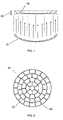
- FIG. 2is an in-plane schematic view showing one of the structures of the micromirror array lens that is made of many micromirrors and actuating components;
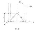
- FIG. 3is a schematic diagram showing how a micromirror array lens works as a lens
- FIG. 4is a schematic diagram showing the cut-away side view of the micromirror array lens with pure translation
- FIG. 5is a schematic diagram showing two rotational axes and one translational axis of the micromirror.
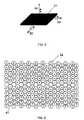
- FIG. 6is a schematic diagram showing the cylindrical lens comprising hexagonal micromirrors.
- FIG. 7is a schematic diagram showing the circular lens comprising hexagonal micromirrors.
- FIG. 8is a schematic diagram showing the cylindrical lens comprising rectangular micromirrors.
- FIG. 9is a schematic diagram showing the circular lens comprising triangular micromirrors.
- FIG. 10is a schematic diagram showing the array of micromirror array lenses comprising hexagonal micromirrors.
- FIG. 11is a schematic diagram showing the array of micromirror array lenses comprising triangular micromirrors.
- FIG. 1illustrates the principle of the micromirror array lens 11 .
- the firstis the converging condition that all light scattered by one point of an object should converge into one point of the image plane.
- the secondis the same phase condition that all converging light should have the same phase at the image plane.
- the surface shape of conventional reflective lens 12is formed to have all light scattered by one point of an objective to be converged into one point of the image plane and have the optical path length of all converging light to be same.
- a micromirror array arranged in flat planecan satisfy two conditions to be a lens.
- Each of the micromirrors 13rotates to converge the scattered light.
- all micromirrors 13 of the micromirror array lens 11are arranged in a flat plane as shown in FIG. 1 , the optical path length of lights converged by rotation of the micromirrors is different. Even though the optical path length of converging light is different, the same phase condition can be satisfied by adjusting the phase because the phase of light is periodic.
- FIG. 2illustrates the in-plane view of the micromirror array lens 21 .
- the micromirror 22has the same function as a mirror. Therefore, the reflective surface of the micromirror 22 is made of metal, metal compound, or other materials with reflectivity. Many known microfabrication processes can make the surface have high reflectivity.
- Each micromirror 22is electrostatically and/or electromagnetically controlled by the actuating components 23 as known.
- the micromirror array lens 21has a polar array of the micromirrors 22 .
- Each of the micromirrors 22has a fan shape to increase an effective reflective area, which increases optical efficiency.
- the micromirrorsare arranged to form one or more concentric circles to form the axisymmetric lens and the micromirrors on same concentric circle can be controlled by the same electrodes with concentric circle shape.
- each reflective micromirror 22 and the actuating components 23are located under the micromirrors 22 to increase the effective reflective area.
- electric circuits to operate the micromirrorscan be replaced with known microelectronics technologies such as MOS or CMOS. Applying the circuits under micromirror array, the effective reflective area can be increased by removing necessary area for electrode pads and wires used to supply actuating power.
- FIG. 3illustrates how the micromirror array lens 31 images.
- Arbitrary scattered lights 32 , 33are converged into one point P of the image plane by controlling the positions of the micromirrors 34 .
- the phases of arbitrary light 32 , 33can be adjusted to be same by translating the micromirrors 34 .
- the required translational displacementis at least half of the wavelength of light.
- each of the micromirrors 34has a curvature because the ideal shape of a conventional reflective lens 12 has a curvature. If the size of the flat micromirror is small enough, the aberration of the lens comprising flat micromirrors 34 is also small enough. In this case, the micromirror does not need a curvature.
- the focal length f of the micromirror array lens 31is changed by controlling the rotation and/or translation of each micromirror 34 .
- the micromirror array lens 31is possible by controlling only rotation without controlling translation even though it has relatively a large aberration. In this case, the imaging quality of the lens 31 formed by controlling only rotation is degraded due to the aberration.
- FIG. 4illustrates the micromirror array lens 42 made by pure translation without rotation of micromirror 41 .
- a conventional reflective lens 44can be replaced by control of rotation and translation of micromirrors 43 .
- Pure translation without rotationcan also satisfy the two imaging conditions by Fresnel diffraction theory.
- the lens 42 formed by the control of only translationhas also the aberration.
- Even though the lens with either translation 42 or rotationhas low quality, it can be used as a lens because its structure and control are much simpler than the lens with both rotation and translation.
- FIG. 5shows two degree of freedom rotations and one degree of freedom translation of the micromirror 51 .
- the array comprising micromirrors 51 with two degree of freedom rotations 52 , 53 or two degree of freedom rotations 52 , 53 and one degree of freedom translation 54 which are controlled independentlycan make a lens with arbitrary shape and/or size, or a lens array comprising lenses with arbitrary shape and/or size.
- Incident lightscan be modulated arbitrarily by forming an arbitrary shape and/or size lens or a lens array comprising lenses with arbitrary shape and/or size. To do this, it is required that incident lights are deflected to arbitrary directions by controls of two degree of freedom rotations 52 , 53 .
- Independent translation 54 of each micromirroris also required to satisfy the phase condition.
- FIGS. 6–11the rotational amount of the micromirror is represented by lengths of arrows 62 , 73 , 83 , 93 , 102 , 112 , respectively and the rotational direction of the micromirror is represented by directions of arrows 62 , 73 , 83 , 93 , 102 , 112 , respectively.
- FIG. 6shows a variable focal length cylindrical lens comprising hexagonal micromirrors 61 .
- FIG. 7shows a variable focal length circular lens 71 comprising hexagonal micromirrors 61 . Shape, position and size of the variable focal length circular lens 71 can be changed by independent control of micromirrors 61 with two rotations and one translation. Even though FIGS.
- FIG. 6 , 7show hexagonal micromirrors 61 , fan shape, rectangle, square, and triangle micromirrors array can be used.
- An array comprising fan shape micromirrorsis appropriate to an axisymmetric lens.
- FIG. 8shows a variable focal length cylindrical lens 81 comprising rectangular micromirrors 82 .
- An array comprising square or rectangle micromirrors 82is appropriate to a symmetric lens about one axis of in-plane such as cylindrical lens 81 .
- FIG. 9shows a variable focal length circular lens 91 comprising triangular micromirrors 92 .
- An array comprising triangular micromirrors 92is appropriate to a lens with arbitrary shape and/or size lens like an array comprising hexagonal micromirrors.
- FIG. 10shows an array of the variable focal length lens 101 comprising hexagonal micromirrors 61 .
- FIG. 11shows an array of the variable focal length lens 111 comprising triangular micromirrors 61 .
- micromirrors 72which are not elements of the lens or lenses are controlled to make lights reflected by the micromirrors 72 not have influence on imaging or focusing.
- the micromirror array lensis an adaptive optical component because the phase of light can be changed by controlling the translations 54 and/or rotations 52 , 53 of micromirrors independently.
- Adaptive optical micromirror array lensrequires two-dimensional arrays of individually addressable micromirrors. To achieve this, it is necessary to combine the micromirrors with on-chip electronics. In order to do this, wafer-level integration of micromirrors with the microelectronics circuits is necessary.
- the micromirror array lenscan correct the phase errors since an adaptive optical component can correct the phase errors of light due to the medium between the object and its image and/or corrects the defects of a lens system that cause its image to deviate from the rules of paraxial imagery.
- the micromirror array lenscan correct the phase error due to optical tilt by adjusting the translations 54 and/or rotations 52 , 53 of micromirrors.
- the same phase condition satisfied by the micromirror array lenscontains an assumption of monochromatic light. Therefore, to get a color image, the micromirror array lens is controlled to satisfy the same phase condition for each wavelength of Red, Green, and Blue (RGB), respectively, and the imaging system can use bandpass filters to make monochromatic lights with wavelengths of Red, Green, and Blue (RGB).
- RGBRed, Green, and Blue
- a color imagecan be obtained by processing electrical signals from Red, Green, and Blue (RGB) imaging sensors with or without bandpass filters, which should be synchronized with the control of micromirror array lens.
- RGBRed, Green, and Blue
- the micromirror array lensis controlled to satisfy the phase condition for Red light.
- Red, Green, and Blue imaging sensorsmeasure the intensity of each Red, Green, and Blue light scattered from an object. Among them, only the intensity of Red light is stored as image data because only Red light is imaged properly.
- the micromirror array lens and each imaging sensorworks in the same manner as the process for the Red light.
- the micromirror array lensis synchronized with Red, Green, and Blue imaging sensors.
- the same phase condition for a color imageis satisfied by using the least common multiple of wavelengths of Red, Green, and Blue lights as effective wavelength for the phase condition.
- the micromirror array lensis not necessary to be controlled to satisfy the phase condition for each Red, Green, and Blue light individually. Instead, the phase condition for the least common multiple of the wavelengths should be satisfied.
- each micromirroris only controlled to satisfy the phase condition for one light among Red, Green, and Blue lights or is not controlled to satisfy the phase condition for any light of Red, Green, and Blue lights.
- the micromirror array lensis not controlled to satisfy the phase condition for all wavelengths, still the lens can be used as a variable focal length lens with low quality.
Landscapes
- Physics & Mathematics (AREA)
- General Physics & Mathematics (AREA)
- Optics & Photonics (AREA)
- Mechanical Light Control Or Optical Switches (AREA)
- Optical Elements Other Than Lenses (AREA)
- Micromachines (AREA)
Abstract
Description
Claims (33)
Priority Applications (21)
| Application Number | Priority Date | Filing Date | Title |
|---|---|---|---|
| US10/857,714US7161729B2 (en) | 2004-05-28 | 2004-05-28 | Array of micromirror array lenses |
| US10/979,624US7261417B2 (en) | 2004-02-13 | 2004-11-02 | Three-dimensional integral imaging and display system using variable focal length lens |
| US10/979,619US7768571B2 (en) | 2004-03-22 | 2004-11-02 | Optical tracking system using variable focal length lens |
| US10/979,612US7173653B2 (en) | 2004-03-22 | 2004-11-02 | Imaging stabilizer using micromirror array lens |
| US10/979,568US7354167B2 (en) | 2004-05-27 | 2004-11-02 | Beam focusing and scanning system using micromirror array lens |
| US10/983,353US7267447B2 (en) | 2004-05-27 | 2004-11-08 | Variable focal length lens comprising micromirrors |
| TW094117167ATWI300492B (en) | 2004-05-28 | 2005-05-26 | Array of micromirror array lenses |
| CA002568615ACA2568615A1 (en) | 2004-05-28 | 2005-05-27 | Array of micromirror array lenses |
| CNA2005800171659ACN1961255A (en) | 2004-05-28 | 2005-05-27 | Array of micromirror array lenses |
| PCT/US2005/018529WO2005119332A2 (en) | 2004-05-28 | 2005-05-27 | Array of micromirror array lenses |
| EP05753942AEP1754107A4 (en) | 2004-05-28 | 2005-05-27 | Array of micromirror array lenses |
| MXPA06013647AMXPA06013647A (en) | 2004-05-28 | 2005-05-27 | Array of micromirror array lenses. |
| BRPI0511651-1ABRPI0511651A (en) | 2004-05-28 | 2005-05-27 | micro-mirror array lens arrangement |
| JP2007515333AJP2008501148A (en) | 2004-05-28 | 2005-05-27 | Micromirror array lens array |
| US11/341,214US7619614B2 (en) | 2004-04-12 | 2006-01-28 | Three-dimensional optical mouse system |
| US11/341,030US7667896B2 (en) | 2004-05-27 | 2006-01-28 | DVD recording and reproducing system |
| US11/359,121US7236289B2 (en) | 2004-05-27 | 2006-02-21 | Fast optical shutter using micromirror motion |
| US11/419,480US8049776B2 (en) | 2004-04-12 | 2006-05-19 | Three-dimensional camcorder |
| US11/423,333US7350922B2 (en) | 2004-02-13 | 2006-06-09 | Three-dimensional display using variable focal length micromirror array lens |
| US11/426,565US7777959B2 (en) | 2004-05-27 | 2006-06-26 | Micromirror array lens with fixed focal length |
| IL179541AIL179541A0 (en) | 2004-05-28 | 2006-11-23 | Array of micromirror array lenses |
Applications Claiming Priority (1)
| Application Number | Priority Date | Filing Date | Title |
|---|---|---|---|
| US10/857,714US7161729B2 (en) | 2004-05-28 | 2004-05-28 | Array of micromirror array lenses |
Related Parent Applications (3)
| Application Number | Title | Priority Date | Filing Date |
|---|---|---|---|
| US10/855,715Continuation-In-PartUS7031046B2 (en) | 2004-02-13 | 2004-05-27 | Variable focal length lens comprising micromirrors with two degrees of freedom rotation |
| US10/857,796Continuation-In-PartUS6934073B1 (en) | 2004-02-13 | 2004-05-28 | Variable focal length lens comprising micromirrors with one degrees of freedom rotation and one degree of freedom translation |
| US10/857,280Continuation-In-PartUS6999226B2 (en) | 2004-02-13 | 2004-05-28 | Variable focal length lens comprising micromirrors with one degree of freedom translation |
Related Child Applications (14)
| Application Number | Title | Priority Date | Filing Date |
|---|---|---|---|
| US10/857,280Continuation-In-PartUS6999226B2 (en) | 2004-02-13 | 2004-05-28 | Variable focal length lens comprising micromirrors with one degree of freedom translation |
| US10/857,796Continuation-In-PartUS6934073B1 (en) | 2004-02-13 | 2004-05-28 | Variable focal length lens comprising micromirrors with one degrees of freedom rotation and one degree of freedom translation |
| US10/872,241Continuation-In-PartUS7382516B2 (en) | 2004-02-13 | 2004-06-18 | Discretely controlled micromirror with multi-level positions |
| US10/979,612Continuation-In-PartUS7173653B2 (en) | 2004-03-22 | 2004-11-02 | Imaging stabilizer using micromirror array lens |
| US10/979,568Continuation-In-PartUS7354167B2 (en) | 2004-05-27 | 2004-11-02 | Beam focusing and scanning system using micromirror array lens |
| US10/979,619Continuation-In-PartUS7768571B2 (en) | 2004-03-22 | 2004-11-02 | Optical tracking system using variable focal length lens |
| US10/979,624Continuation-In-PartUS7261417B2 (en) | 2004-02-13 | 2004-11-02 | Three-dimensional integral imaging and display system using variable focal length lens |
| US10/983,353Continuation-In-PartUS7267447B2 (en) | 2004-02-13 | 2004-11-08 | Variable focal length lens comprising micromirrors |
| US11/341,214Continuation-In-PartUS7619614B2 (en) | 2004-04-12 | 2006-01-28 | Three-dimensional optical mouse system |
| US11/341,030Continuation-In-PartUS7667896B2 (en) | 2004-05-27 | 2006-01-28 | DVD recording and reproducing system |
| US11/359,121Continuation-In-PartUS7236289B2 (en) | 2004-05-27 | 2006-02-21 | Fast optical shutter using micromirror motion |
| US11/419,480Continuation-In-PartUS8049776B2 (en) | 2004-04-12 | 2006-05-19 | Three-dimensional camcorder |
| US11/423,333Continuation-In-PartUS7350922B2 (en) | 2004-02-13 | 2006-06-09 | Three-dimensional display using variable focal length micromirror array lens |
| US11/426,565Continuation-In-PartUS7777959B2 (en) | 2004-05-27 | 2006-06-26 | Micromirror array lens with fixed focal length |
Publications (2)
| Publication Number | Publication Date |
|---|---|
| US20050275929A1 US20050275929A1 (en) | 2005-12-15 |
| US7161729B2true US7161729B2 (en) | 2007-01-09 |
Family
ID=35460236
Family Applications (1)
| Application Number | Title | Priority Date | Filing Date |
|---|---|---|---|
| US10/857,714Expired - LifetimeUS7161729B2 (en) | 2004-02-13 | 2004-05-28 | Array of micromirror array lenses |
Country Status (10)
| Country | Link |
|---|---|
| US (1) | US7161729B2 (en) |
| EP (1) | EP1754107A4 (en) |
| JP (1) | JP2008501148A (en) |
| CN (1) | CN1961255A (en) |
| BR (1) | BRPI0511651A (en) |
| CA (1) | CA2568615A1 (en) |
| IL (1) | IL179541A0 (en) |
| MX (1) | MXPA06013647A (en) |
| TW (1) | TWI300492B (en) |
| WO (1) | WO2005119332A2 (en) |
Cited By (41)
| Publication number | Priority date | Publication date | Assignee | Title |
|---|---|---|---|---|
| US20050206773A1 (en)* | 2004-03-22 | 2005-09-22 | Kim Tae H | Optical tracking system using variable focal length lens |
| US20050264870A1 (en)* | 2004-05-27 | 2005-12-01 | Angstrom Inc. | Variable focal length lens comprising micromirrors |
| US20050280883A1 (en)* | 2004-06-18 | 2005-12-22 | Angstrom Inc. & Stereo Display Inc. | Discretely controlled micromirror with multi-level positions |
| US20060007301A1 (en)* | 2004-07-08 | 2006-01-12 | Cho Gyoung I | 3D television broadcasting system |
| US20060092379A1 (en)* | 2004-02-13 | 2006-05-04 | Stereo Display, Inc. | Image-guided microsurgery system and method |
| US20060120706A1 (en)* | 2004-02-13 | 2006-06-08 | Stereo Display, Inc. | Three-dimensional endoscope imaging and display system |
| US20060152792A1 (en)* | 2004-06-18 | 2006-07-13 | Stereo Display, Inc. | Programmable micromirror motion control system |
| US20060158432A1 (en)* | 2004-04-12 | 2006-07-20 | Stereo Dispaly, Inc. | Three-dimensional optical mouse system |
| US20060198011A1 (en)* | 2005-03-04 | 2006-09-07 | Stereo Display, Inc. | Volumetric three-dimensional device using two-dimensional scanning device |
| US20060198012A1 (en)* | 2005-03-04 | 2006-09-07 | Stereo Display, Inc. | Fine control of rotation and translation of discretely controlled micromirror |
| US20060203117A1 (en)* | 2005-03-10 | 2006-09-14 | Stereo Display, Inc. | Video monitoring system using variable focal length lens |
| US20060209423A1 (en)* | 2004-03-22 | 2006-09-21 | Angstrom Inc. & Stereo Display Inc. | Small and fast zoom system using micromirror array lens |
| US20060209439A1 (en)* | 2004-04-12 | 2006-09-21 | Stereo Display, Inc. | Three-dimensional imaging system |
| US20060221179A1 (en)* | 2004-04-12 | 2006-10-05 | Stereo Display, Inc. | Three-dimensional camcorder |
| US20060232498A1 (en)* | 2004-02-13 | 2006-10-19 | Stereo Display, Inc. | Three-dimensional display using variable focal length micromirror array lens |
| US20060245067A1 (en)* | 2004-05-27 | 2006-11-02 | Stereo Display, Inc. | Micromirror array lens with fixed focal length |
| US20070041077A1 (en)* | 2005-08-19 | 2007-02-22 | Stereo Display, Inc. | Pocket-sized two-dimensional image projection system |
| US20070040924A1 (en)* | 2005-08-19 | 2007-02-22 | Stereo Display, Inc. | Cellular phone camera with three-dimensional imaging function |
| US20070115261A1 (en)* | 2005-11-23 | 2007-05-24 | Stereo Display, Inc. | Virtual Keyboard input system using three-dimensional motion detection by variable focal length lens |
| US20070182276A1 (en)* | 2006-02-04 | 2007-08-09 | Stereo Display, Inc. | Multi-step microactuator |
| US20070188883A1 (en)* | 2004-03-22 | 2007-08-16 | Stereo Display, Inc. | Three-dimensional imaging system for robot vision |
| US20080037102A1 (en)* | 2006-08-10 | 2008-02-14 | Stereo Display, Inc. | Micromirror with multi-axis rotation and translation |
| US20080049291A1 (en)* | 2004-11-08 | 2008-02-28 | Stereo Display, Inc. | Micromirror arry lens with optical surface profiles |
| US20080074726A1 (en)* | 2006-09-22 | 2008-03-27 | Stereo Display, Inc. | Micromirror array lens with encapsulation of reflective metal layer and method of making the same |
| US20080074727A1 (en)* | 2006-09-22 | 2008-03-27 | Stereo Display, Inc. | Micromirror array device comprising encapsulated reflective metal layer and method of making the same |
| US7354167B2 (en) | 2004-05-27 | 2008-04-08 | Angstrom, Inc. | Beam focusing and scanning system using micromirror array lens |
| US20080225369A1 (en)* | 2007-03-12 | 2008-09-18 | Stereo Display, Inc. | Discretely controlled micromirror device having multiple motions |
| US20080309190A1 (en)* | 2007-06-13 | 2008-12-18 | Stereo Display, Inc. | Mems actuator with discretely controlled multiple motions |
| US20090027780A1 (en)* | 2007-07-23 | 2009-01-29 | Stereo Display, Inc. | Compact image taking lens system with a lens-surfaced prism |
| US7488082B2 (en) | 2006-12-12 | 2009-02-10 | Angstrom, Inc. | Discretely controlled micromirror array device with segmented electrodes |
| US7489434B2 (en) | 2007-05-02 | 2009-02-10 | Angstrom, Inc. | Hybrid micromirror array lens for reducing chromatic aberration |
| US20090040586A1 (en)* | 2007-08-10 | 2009-02-12 | Stereo Display, Inc. | Micromirror arry with iris function |
| US20090185067A1 (en)* | 2007-12-21 | 2009-07-23 | Stereo Display, Inc. | Compact automatic focusing camera |
| US20090237783A1 (en)* | 2008-03-18 | 2009-09-24 | Stereo Display, Inc. | Binoculars with micromirror array lenses |
| US20090290244A1 (en)* | 2008-05-20 | 2009-11-26 | Stereo Display, Inc. | Micromirror array lens with self-tilted micromirrors |
| US20090303569A1 (en)* | 2008-05-20 | 2009-12-10 | Stereo Didplay, Inc. | Self-tilted micromirror device |
| US7667896B2 (en) | 2004-05-27 | 2010-02-23 | Angstrom, Inc. | DVD recording and reproducing system |
| US8503087B1 (en)* | 2010-11-02 | 2013-08-06 | Google Inc. | Structured optical surface |
| US9736346B2 (en) | 2006-05-09 | 2017-08-15 | Stereo Display, Inc | Imaging system improving image resolution of the system with low resolution image sensor |
| US11917121B2 (en) | 2019-06-28 | 2024-02-27 | Interdigital Madison Patent Holdings, Sas | Optical method and system for light field (LF) displays based on tunable liquid crystal (LC) diffusers |
| US11991343B2 (en) | 2019-06-07 | 2024-05-21 | Interdigital Madison Patent Holdings, Sas | Optical method and system for light field displays based on distributed apertures |
Families Citing this family (9)
| Publication number | Priority date | Publication date | Assignee | Title |
|---|---|---|---|---|
| CN101487906B (en)* | 2009-02-23 | 2010-06-02 | 南京邮电大学 | Fabrication method of electrically tuned microfluidic zoom lens array chip |
| JP5701573B2 (en)* | 2010-06-15 | 2015-04-15 | オリンパス株式会社 | Scanner, scanning illumination device, and scanning observation device |
| US9475649B2 (en) | 2010-12-15 | 2016-10-25 | Symbolic, LLC | Pickface builder for storage and retrieval systems |
| JP2013210610A (en)* | 2012-02-29 | 2013-10-10 | Nitto Denko Corp | Micromirror array |
| KR102140733B1 (en)* | 2018-11-06 | 2020-08-03 | 주식회사 레티널 | Optical device for augmented reality |
| CN113281898B (en)* | 2021-05-25 | 2022-08-05 | 中国科学院上海微系统与信息技术研究所 | MEMS Micromirror Unit and MEMS Micromirror Array |
| CN113433773A (en)* | 2021-07-27 | 2021-09-24 | 上海赛图图像设备有限公司 | Digital micromirror combined LED image three-dimensional light source system |
| CN113820850B (en)* | 2021-08-23 | 2023-08-11 | 中国科学院光电技术研究所 | MEMS micro-shutter array device integrated with spherical reflector |
| CN114967108B (en)* | 2022-08-01 | 2022-10-21 | 加维纳米(北京)科技有限公司 | Digital micromirror array chip preparation method and digital micromirror array chip |
Citations (21)
| Publication number | Priority date | Publication date | Assignee | Title |
|---|---|---|---|---|
| US2002376A (en) | 1931-03-16 | 1935-05-21 | Mannheimer Manfred | Searchlight reflector |
| US4834512A (en) | 1984-12-21 | 1989-05-30 | Hughes Aircraft Company | Three-dimensional display |
| US5004319A (en)* | 1988-12-29 | 1991-04-02 | The United States Of America As Represented By The Department Of Energy | Crystal diffraction lens with variable focal length |
| US5986811A (en) | 1995-06-07 | 1999-11-16 | Meso Scale Technologies Llp | Method of and apparatus for generating a 3-D image from a 2-D image having a changeable focusing micro-lens array |
| US6111900A (en) | 1997-03-13 | 2000-08-29 | Ricoh Company, Ltd. | Solid-state laser apparatus and method with second harmonic wave features |
| US20020102102A1 (en) | 2001-01-30 | 2002-08-01 | Yoji Watanabe | Focal-length adjusting unit for photographing apparatuses |
| US20030058520A1 (en)* | 2001-02-09 | 2003-03-27 | Kyoungsik Yu | Reconfigurable wavelength multiplexers and filters employing micromirror array in a gires-tournois interferometer |
| US6549730B1 (en)* | 1999-09-29 | 2003-04-15 | Minolta Co., Ltd. | Focal position changeable spatial modulation unit and focus detection device |
| US6784771B1 (en)* | 2001-07-24 | 2004-08-31 | New Peregrine, Inc. | MEMS optical mirror array |
| US6833938B2 (en) | 2000-01-26 | 2004-12-21 | Olympus Corporation | Variable hologram element, and optical device using the same |
| US20050057812A1 (en) | 2003-01-13 | 2005-03-17 | Raber Peter E. | Variable focus system |
| US6900922B2 (en)* | 2003-02-24 | 2005-05-31 | Exajoule, Llc | Multi-tilt micromirror systems with concealed hinge structures |
| US6906848B2 (en)* | 2003-02-24 | 2005-06-14 | Exajoule, Llc | Micromirror systems with concealed multi-piece hinge structures |
| US6934073B1 (en)* | 2004-05-28 | 2005-08-23 | Angstrom Inc. | Variable focal length lens comprising micromirrors with one degrees of freedom rotation and one degree of freedom translation |
| US20050225884A1 (en)* | 2004-04-12 | 2005-10-13 | Gim Dong W | Three-dimensional imaging device |
| US6970284B1 (en)* | 2004-05-27 | 2005-11-29 | Angstrom Inc. | Variable focusing lens comprising micromirrors with one degree of freedom rotation |
| US20050264867A1 (en)* | 2004-05-27 | 2005-12-01 | Cho Gyoung I | Beam focusing and scanning system using micromirror array lens |
| US20050264870A1 (en)* | 2004-05-27 | 2005-12-01 | Angstrom Inc. | Variable focal length lens comprising micromirrors |
| US20060012852A1 (en)* | 2004-07-16 | 2006-01-19 | Angstrom Inc. & Stereo Display Inc. | Variable focal length lens and lens array comprising discretely controlled micromirrors |
| US20060028709A1 (en)* | 2004-08-09 | 2006-02-09 | Stereo Display, Inc. | Two-dimensional image projection system |
| US6999226B2 (en)* | 2004-05-28 | 2006-02-14 | Angstrom Inc. | Variable focal length lens comprising micromirrors with one degree of freedom translation |
Family Cites Families (3)
| Publication number | Priority date | Publication date | Assignee | Title |
|---|---|---|---|---|
| US7077523B2 (en)* | 2004-02-13 | 2006-07-18 | Angstorm Inc. | Three-dimensional display using variable focusing lens |
| US6934072B1 (en)* | 2004-05-27 | 2005-08-23 | Angstrom Inc. | Variable focal length lens comprising micromirrors with two degrees of freedom rotation and one degree of freedom translation |
| US7057826B2 (en)* | 2004-03-22 | 2006-06-06 | Angstrom Inc. | Small and fast zoom system |
- 2004
- 2004-05-28USUS10/857,714patent/US7161729B2/ennot_activeExpired - Lifetime
- 2005
- 2005-05-26TWTW094117167Apatent/TWI300492B/ennot_activeIP Right Cessation
- 2005-05-27WOPCT/US2005/018529patent/WO2005119332A2/enactiveApplication Filing
- 2005-05-27CACA002568615Apatent/CA2568615A1/ennot_activeAbandoned
- 2005-05-27MXMXPA06013647Apatent/MXPA06013647A/enactiveIP Right Grant
- 2005-05-27EPEP05753942Apatent/EP1754107A4/ennot_activeWithdrawn
- 2005-05-27BRBRPI0511651-1Apatent/BRPI0511651A/ennot_activeIP Right Cessation
- 2005-05-27JPJP2007515333Apatent/JP2008501148A/enactivePending
- 2005-05-27CNCNA2005800171659Apatent/CN1961255A/enactivePending
- 2006
- 2006-11-23ILIL179541Apatent/IL179541A0/enunknown
Patent Citations (22)
| Publication number | Priority date | Publication date | Assignee | Title |
|---|---|---|---|---|
| US2002376A (en) | 1931-03-16 | 1935-05-21 | Mannheimer Manfred | Searchlight reflector |
| US4834512A (en) | 1984-12-21 | 1989-05-30 | Hughes Aircraft Company | Three-dimensional display |
| US5004319A (en)* | 1988-12-29 | 1991-04-02 | The United States Of America As Represented By The Department Of Energy | Crystal diffraction lens with variable focal length |
| US5986811A (en) | 1995-06-07 | 1999-11-16 | Meso Scale Technologies Llp | Method of and apparatus for generating a 3-D image from a 2-D image having a changeable focusing micro-lens array |
| US6111900A (en) | 1997-03-13 | 2000-08-29 | Ricoh Company, Ltd. | Solid-state laser apparatus and method with second harmonic wave features |
| US6549730B1 (en)* | 1999-09-29 | 2003-04-15 | Minolta Co., Ltd. | Focal position changeable spatial modulation unit and focus detection device |
| US6833938B2 (en) | 2000-01-26 | 2004-12-21 | Olympus Corporation | Variable hologram element, and optical device using the same |
| US20020102102A1 (en) | 2001-01-30 | 2002-08-01 | Yoji Watanabe | Focal-length adjusting unit for photographing apparatuses |
| US6658208B2 (en) | 2001-01-30 | 2003-12-02 | Olympus Optical Co., Ltd. | Focal-length adjusting unit for photographing apparatuses |
| US20030058520A1 (en)* | 2001-02-09 | 2003-03-27 | Kyoungsik Yu | Reconfigurable wavelength multiplexers and filters employing micromirror array in a gires-tournois interferometer |
| US6784771B1 (en)* | 2001-07-24 | 2004-08-31 | New Peregrine, Inc. | MEMS optical mirror array |
| US20050057812A1 (en) | 2003-01-13 | 2005-03-17 | Raber Peter E. | Variable focus system |
| US6900922B2 (en)* | 2003-02-24 | 2005-05-31 | Exajoule, Llc | Multi-tilt micromirror systems with concealed hinge structures |
| US6906848B2 (en)* | 2003-02-24 | 2005-06-14 | Exajoule, Llc | Micromirror systems with concealed multi-piece hinge structures |
| US20050225884A1 (en)* | 2004-04-12 | 2005-10-13 | Gim Dong W | Three-dimensional imaging device |
| US20050264867A1 (en)* | 2004-05-27 | 2005-12-01 | Cho Gyoung I | Beam focusing and scanning system using micromirror array lens |
| US6970284B1 (en)* | 2004-05-27 | 2005-11-29 | Angstrom Inc. | Variable focusing lens comprising micromirrors with one degree of freedom rotation |
| US20050264870A1 (en)* | 2004-05-27 | 2005-12-01 | Angstrom Inc. | Variable focal length lens comprising micromirrors |
| US6934073B1 (en)* | 2004-05-28 | 2005-08-23 | Angstrom Inc. | Variable focal length lens comprising micromirrors with one degrees of freedom rotation and one degree of freedom translation |
| US6999226B2 (en)* | 2004-05-28 | 2006-02-14 | Angstrom Inc. | Variable focal length lens comprising micromirrors with one degree of freedom translation |
| US20060012852A1 (en)* | 2004-07-16 | 2006-01-19 | Angstrom Inc. & Stereo Display Inc. | Variable focal length lens and lens array comprising discretely controlled micromirrors |
| US20060028709A1 (en)* | 2004-08-09 | 2006-02-09 | Stereo Display, Inc. | Two-dimensional image projection system |
Non-Patent Citations (2)
| Title |
|---|
| Cho, 2003, "Fast-response Variable Focusing Micromirror Array Lens," Proceeding of SPIE vol. 5055: 278-286. |
| Kaneko et al., 2000, "Quick Response Dynamic Focusing Lens using Multi-Layered Piezoelectric Bimorph Actuator," Proceeding of SPIE vol. 4075: 24-31. |
Cited By (69)
| Publication number | Priority date | Publication date | Assignee | Title |
|---|---|---|---|---|
| US7751694B2 (en) | 2004-02-13 | 2010-07-06 | Angstrom, Inc. | Three-dimensional endoscope imaging and display system |
| US7350922B2 (en) | 2004-02-13 | 2008-04-01 | Angstrom, Inc. | Three-dimensional display using variable focal length micromirror array lens |
| US20060232498A1 (en)* | 2004-02-13 | 2006-10-19 | Stereo Display, Inc. | Three-dimensional display using variable focal length micromirror array lens |
| US7580178B2 (en) | 2004-02-13 | 2009-08-25 | Angstrom, Inc. | Image-guided microsurgery system and method |
| US20060092379A1 (en)* | 2004-02-13 | 2006-05-04 | Stereo Display, Inc. | Image-guided microsurgery system and method |
| US20060120706A1 (en)* | 2004-02-13 | 2006-06-08 | Stereo Display, Inc. | Three-dimensional endoscope imaging and display system |
| US20070188883A1 (en)* | 2004-03-22 | 2007-08-16 | Stereo Display, Inc. | Three-dimensional imaging system for robot vision |
| US7339746B2 (en) | 2004-03-22 | 2008-03-04 | Angstrom, Inc. | Small and fast zoom system using micromirror array lens |
| US7410266B2 (en) | 2004-03-22 | 2008-08-12 | Angstrom, Inc. | Three-dimensional imaging system for robot vision |
| US20060209423A1 (en)* | 2004-03-22 | 2006-09-21 | Angstrom Inc. & Stereo Display Inc. | Small and fast zoom system using micromirror array lens |
| US20050206773A1 (en)* | 2004-03-22 | 2005-09-22 | Kim Tae H | Optical tracking system using variable focal length lens |
| US7768571B2 (en) | 2004-03-22 | 2010-08-03 | Angstrom, Inc. | Optical tracking system using variable focal length lens |
| US8049776B2 (en) | 2004-04-12 | 2011-11-01 | Angstrom, Inc. | Three-dimensional camcorder |
| US7742232B2 (en) | 2004-04-12 | 2010-06-22 | Angstrom, Inc. | Three-dimensional imaging system |
| US20060209439A1 (en)* | 2004-04-12 | 2006-09-21 | Stereo Display, Inc. | Three-dimensional imaging system |
| US20060221179A1 (en)* | 2004-04-12 | 2006-10-05 | Stereo Display, Inc. | Three-dimensional camcorder |
| US7619614B2 (en) | 2004-04-12 | 2009-11-17 | Angstrom, Inc. | Three-dimensional optical mouse system |
| US20060158432A1 (en)* | 2004-04-12 | 2006-07-20 | Stereo Dispaly, Inc. | Three-dimensional optical mouse system |
| US7777959B2 (en) | 2004-05-27 | 2010-08-17 | Angstrom, Inc. | Micromirror array lens with fixed focal length |
| US20060245067A1 (en)* | 2004-05-27 | 2006-11-02 | Stereo Display, Inc. | Micromirror array lens with fixed focal length |
| US7354167B2 (en) | 2004-05-27 | 2008-04-08 | Angstrom, Inc. | Beam focusing and scanning system using micromirror array lens |
| US7267447B2 (en)* | 2004-05-27 | 2007-09-11 | Angstrom, Inc. | Variable focal length lens comprising micromirrors |
| US7667896B2 (en) | 2004-05-27 | 2010-02-23 | Angstrom, Inc. | DVD recording and reproducing system |
| US20050264870A1 (en)* | 2004-05-27 | 2005-12-01 | Angstrom Inc. | Variable focal length lens comprising micromirrors |
| US20070064301A1 (en)* | 2004-06-18 | 2007-03-22 | Stereo Display, Inc. | Discretely controlled micromirror with multi-level positions |
| US7474454B2 (en) | 2004-06-18 | 2009-01-06 | Angstrom, Inc. | Programmable micromirror motion control system |
| US20050280883A1 (en)* | 2004-06-18 | 2005-12-22 | Angstrom Inc. & Stereo Display Inc. | Discretely controlled micromirror with multi-level positions |
| US20060152792A1 (en)* | 2004-06-18 | 2006-07-13 | Stereo Display, Inc. | Programmable micromirror motion control system |
| US7400437B2 (en) | 2004-06-18 | 2008-07-15 | Angstrom, Inc. | Discretely controlled micromirror with multi-level positions |
| US7382516B2 (en) | 2004-06-18 | 2008-06-03 | Angstrom, Inc. | Discretely controlled micromirror with multi-level positions |
| US8537204B2 (en) | 2004-07-08 | 2013-09-17 | Gyoung Il Cho | 3D television broadcasting system |
| US20060007301A1 (en)* | 2004-07-08 | 2006-01-12 | Cho Gyoung I | 3D television broadcasting system |
| US7619807B2 (en) | 2004-11-08 | 2009-11-17 | Angstrom, Inc. | Micromirror array lens with optical surface profiles |
| US20080049291A1 (en)* | 2004-11-08 | 2008-02-28 | Stereo Display, Inc. | Micromirror arry lens with optical surface profiles |
| US20060198011A1 (en)* | 2005-03-04 | 2006-09-07 | Stereo Display, Inc. | Volumetric three-dimensional device using two-dimensional scanning device |
| US7330297B2 (en) | 2005-03-04 | 2008-02-12 | Angstrom, Inc | Fine control of rotation and translation of discretely controlled micromirror |
| US20060198012A1 (en)* | 2005-03-04 | 2006-09-07 | Stereo Display, Inc. | Fine control of rotation and translation of discretely controlled micromirror |
| US20060203117A1 (en)* | 2005-03-10 | 2006-09-14 | Stereo Display, Inc. | Video monitoring system using variable focal length lens |
| US20070040924A1 (en)* | 2005-08-19 | 2007-02-22 | Stereo Display, Inc. | Cellular phone camera with three-dimensional imaging function |
| US20070041077A1 (en)* | 2005-08-19 | 2007-02-22 | Stereo Display, Inc. | Pocket-sized two-dimensional image projection system |
| US20070115261A1 (en)* | 2005-11-23 | 2007-05-24 | Stereo Display, Inc. | Virtual Keyboard input system using three-dimensional motion detection by variable focal length lens |
| US7898144B2 (en) | 2006-02-04 | 2011-03-01 | Angstrom, Inc. | Multi-step microactuator providing multi-step displacement to a controlled object |
| US20070182276A1 (en)* | 2006-02-04 | 2007-08-09 | Stereo Display, Inc. | Multi-step microactuator |
| US9736346B2 (en) | 2006-05-09 | 2017-08-15 | Stereo Display, Inc | Imaging system improving image resolution of the system with low resolution image sensor |
| US20080037102A1 (en)* | 2006-08-10 | 2008-02-14 | Stereo Display, Inc. | Micromirror with multi-axis rotation and translation |
| US20080074727A1 (en)* | 2006-09-22 | 2008-03-27 | Stereo Display, Inc. | Micromirror array device comprising encapsulated reflective metal layer and method of making the same |
| US7589885B2 (en) | 2006-09-22 | 2009-09-15 | Angstrom, Inc. | Micromirror array device comprising encapsulated reflective metal layer and method of making the same |
| US7589884B2 (en) | 2006-09-22 | 2009-09-15 | Angstrom, Inc. | Micromirror array lens with encapsulation of reflective metal layer and method of making the same |
| US20080074726A1 (en)* | 2006-09-22 | 2008-03-27 | Stereo Display, Inc. | Micromirror array lens with encapsulation of reflective metal layer and method of making the same |
| US7488082B2 (en) | 2006-12-12 | 2009-02-10 | Angstrom, Inc. | Discretely controlled micromirror array device with segmented electrodes |
| US20080225369A1 (en)* | 2007-03-12 | 2008-09-18 | Stereo Display, Inc. | Discretely controlled micromirror device having multiple motions |
| US7535618B2 (en) | 2007-03-12 | 2009-05-19 | Angstrom, Inc. | Discretely controlled micromirror device having multiple motions |
| US7489434B2 (en) | 2007-05-02 | 2009-02-10 | Angstrom, Inc. | Hybrid micromirror array lens for reducing chromatic aberration |
| US20080309190A1 (en)* | 2007-06-13 | 2008-12-18 | Stereo Display, Inc. | Mems actuator with discretely controlled multiple motions |
| US9505606B2 (en) | 2007-06-13 | 2016-11-29 | Angstrom, Inc. | MEMS actuator with discretely controlled multiple motions |
| US7605988B2 (en) | 2007-07-23 | 2009-10-20 | Angstrom, Inc. | Compact image taking lens system with a lens-surfaced prism |
| US20090027780A1 (en)* | 2007-07-23 | 2009-01-29 | Stereo Display, Inc. | Compact image taking lens system with a lens-surfaced prism |
| US7589916B2 (en) | 2007-08-10 | 2009-09-15 | Angstrom, Inc. | Micromirror array with iris function |
| US20090040586A1 (en)* | 2007-08-10 | 2009-02-12 | Stereo Display, Inc. | Micromirror arry with iris function |
| US20090185067A1 (en)* | 2007-12-21 | 2009-07-23 | Stereo Display, Inc. | Compact automatic focusing camera |
| US8810908B2 (en) | 2008-03-18 | 2014-08-19 | Stereo Display, Inc. | Binoculars with micromirror array lenses |
| US20090237783A1 (en)* | 2008-03-18 | 2009-09-24 | Stereo Display, Inc. | Binoculars with micromirror array lenses |
| US20090290244A1 (en)* | 2008-05-20 | 2009-11-26 | Stereo Display, Inc. | Micromirror array lens with self-tilted micromirrors |
| US8622557B2 (en) | 2008-05-20 | 2014-01-07 | Stereo Display, Inc. | Micromirror array lens with self-tilted micromirrors |
| US20090303569A1 (en)* | 2008-05-20 | 2009-12-10 | Stereo Didplay, Inc. | Self-tilted micromirror device |
| US8503087B1 (en)* | 2010-11-02 | 2013-08-06 | Google Inc. | Structured optical surface |
| US11991343B2 (en) | 2019-06-07 | 2024-05-21 | Interdigital Madison Patent Holdings, Sas | Optical method and system for light field displays based on distributed apertures |
| US11917121B2 (en) | 2019-06-28 | 2024-02-27 | Interdigital Madison Patent Holdings, Sas | Optical method and system for light field (LF) displays based on tunable liquid crystal (LC) diffusers |
| US12395617B2 (en) | 2019-06-28 | 2025-08-19 | Interdigital Madison Patent Holdings, Sas | Optical method and system for light field (LF) displays based on tunable liquid crystal (LC) diffusers |
Also Published As
| Publication number | Publication date |
|---|---|
| IL179541A0 (en) | 2007-05-15 |
| JP2008501148A (en) | 2008-01-17 |
| TWI300492B (en) | 2008-09-01 |
| WO2005119332A3 (en) | 2006-02-16 |
| CN1961255A (en) | 2007-05-09 |
| CA2568615A1 (en) | 2005-12-15 |
| US20050275929A1 (en) | 2005-12-15 |
| BRPI0511651A (en) | 2008-01-02 |
| EP1754107A4 (en) | 2007-12-12 |
| TW200602681A (en) | 2006-01-16 |
| WO2005119332A2 (en) | 2005-12-15 |
| MXPA06013647A (en) | 2007-03-23 |
| EP1754107A2 (en) | 2007-02-21 |
Similar Documents
| Publication | Publication Date | Title |
|---|---|---|
| US7161729B2 (en) | Array of micromirror array lenses | |
| US6934072B1 (en) | Variable focal length lens comprising micromirrors with two degrees of freedom rotation and one degree of freedom translation | |
| US6934073B1 (en) | Variable focal length lens comprising micromirrors with one degrees of freedom rotation and one degree of freedom translation | |
| US6999226B2 (en) | Variable focal length lens comprising micromirrors with one degree of freedom translation | |
| US7411718B2 (en) | Variable focal length lens and lens array comprising discretely controlled micromirrors | |
| US7267447B2 (en) | Variable focal length lens comprising micromirrors | |
| US7031046B2 (en) | Variable focal length lens comprising micromirrors with two degrees of freedom rotation | |
| US6970284B1 (en) | Variable focusing lens comprising micromirrors with one degree of freedom rotation | |
| US7068416B2 (en) | Three-dimensional imaging device | |
| US7057826B2 (en) | Small and fast zoom system | |
| KR20070035521A (en) | Array of micromirror array lenses | |
| KR20070030853A (en) | Variable Focal Length Lens |
Legal Events
| Date | Code | Title | Description |
|---|---|---|---|
| AS | Assignment | Owner name:ANGSTROM INC., KOREA, REPUBLIC OF Free format text:ASSIGNMENT OF ASSIGNORS INTEREST;ASSIGNORS:KIM, TAE HYEON;BAEK, SANG HYUNE;REEL/FRAME:015414/0189 Effective date:20040528 Owner name:STEREO DISPLAY INC., CALIFORNIA Free format text:ASSIGNMENT OF ASSIGNORS INTEREST;ASSIGNORS:KIM, TAE HYEON;BAEK, SANG HYUNE;REEL/FRAME:015414/0189 Effective date:20040528 | |
| REMI | Maintenance fee reminder mailed | ||
| LAPS | Lapse for failure to pay maintenance fees | ||
| REIN | Reinstatement after maintenance fee payment confirmed | ||
| FP | Lapsed due to failure to pay maintenance fee | Effective date:20110109 | |
| FEPP | Fee payment procedure | Free format text:PETITION RELATED TO MAINTENANCE FEES DISMISSED (ORIGINAL EVENT CODE: PMFS); ENTITY STATUS OF PATENT OWNER: SMALL ENTITY | |
| FEPP | Fee payment procedure | Free format text:PETITION RELATED TO MAINTENANCE FEES FILED (ORIGINAL EVENT CODE: PMFP); ENTITY STATUS OF PATENT OWNER: SMALL ENTITY | |
| FEPP | Fee payment procedure | Free format text:PETITION RELATED TO MAINTENANCE FEES GRANTED (ORIGINAL EVENT CODE: PMFG); ENTITY STATUS OF PATENT OWNER: SMALL ENTITY | |
| FEPP | Fee payment procedure | Free format text:PETITION RELATED TO MAINTENANCE FEES FILED (ORIGINAL EVENT CODE: PMFP); ENTITY STATUS OF PATENT OWNER: SMALL ENTITY | |
| FEPP | Fee payment procedure | Free format text:PETITION RELATED TO MAINTENANCE FEES FILED (ORIGINAL EVENT CODE: PMFP); ENTITY STATUS OF PATENT OWNER: SMALL ENTITY Free format text:PETITION RELATED TO MAINTENANCE FEES DISMISSED (ORIGINAL EVENT CODE: PMFS); ENTITY STATUS OF PATENT OWNER: SMALL ENTITY | |
| FEPP | Fee payment procedure | Free format text:PETITION RELATED TO MAINTENANCE FEES DISMISSED (ORIGINAL EVENT CODE: PMFS); ENTITY STATUS OF PATENT OWNER: SMALL ENTITY | |
| FEPP | Fee payment procedure | Free format text:PETITION RELATED TO MAINTENANCE FEES FILED (ORIGINAL EVENT CODE: PMFP); ENTITY STATUS OF PATENT OWNER: SMALL ENTITY | |
| FPAY | Fee payment | Year of fee payment:4 | |
| PRDP | Patent reinstated due to the acceptance of a late maintenance fee | Effective date:20141001 | |
| STCF | Information on status: patent grant | Free format text:PATENTED CASE | |
| FPAY | Fee payment | Year of fee payment:8 | |
| SULP | Surcharge for late payment | Year of fee payment:7 | |
| FEPP | Fee payment procedure | Free format text:MAINTENANCE FEE REMINDER MAILED (ORIGINAL EVENT CODE: REM.); ENTITY STATUS OF PATENT OWNER: SMALL ENTITY | |
| FEPP | Fee payment procedure | Free format text:11.5 YR SURCHARGE- LATE PMT W/IN 6 MO, SMALL ENTITY (ORIGINAL EVENT CODE: M2556); ENTITY STATUS OF PATENT OWNER: SMALL ENTITY | |
| MAFP | Maintenance fee payment | Free format text:PAYMENT OF MAINTENANCE FEE, 12TH YR, SMALL ENTITY (ORIGINAL EVENT CODE: M2553); ENTITY STATUS OF PATENT OWNER: SMALL ENTITY Year of fee payment:12 | |
| AS | Assignment | Owner name:INC., STEREO D, INC., CALIFORNIA Free format text:ASSIGNMENT OF ASSIGNORS INTEREST;ASSIGNOR:ANGSTROM, INC.;REEL/FRAME:054680/0198 Effective date:20191212 | |
| AS | Assignment | Owner name:STEREO DISPLAY, INC., CALIFORNIA Free format text:CORRECTIVE ASSIGNMENT TO CORRECT THE THE ASSIGNEE NAME PREVIOUSLY RECORDED AT REEL: 054680 FRAME: 0198. ASSIGNOR(S) HEREBY CONFIRMS THE ASSIGNMENT;ASSIGNOR:ANGSTROM, INC.;REEL/FRAME:056846/0253 Effective date:20191212 |