US7160302B2 - Intramedullary interlocking fixation device for the distal radius - Google Patents
Intramedullary interlocking fixation device for the distal radiusDownload PDFInfo
- Publication number
- US7160302B2 US7160302B2US10/377,255US37725503AUS7160302B2US 7160302 B2US7160302 B2US 7160302B2US 37725503 AUS37725503 AUS 37725503AUS 7160302 B2US7160302 B2US 7160302B2
- Authority
- US
- United States
- Prior art keywords
- distal
- fixation member
- radius
- proximal
- elongated
- Prior art date
- Legal status (The legal status is an assumption and is not a legal conclusion. Google has not performed a legal analysis and makes no representation as to the accuracy of the status listed.)
- Expired - Lifetime, expires
Links
Images


Classifications
- A—HUMAN NECESSITIES
- A61—MEDICAL OR VETERINARY SCIENCE; HYGIENE
- A61B—DIAGNOSIS; SURGERY; IDENTIFICATION
- A61B17/00—Surgical instruments, devices or methods
- A61B17/16—Instruments for performing osteoclasis; Drills or chisels for bones; Trepans
- A61B17/164—Instruments for performing osteoclasis; Drills or chisels for bones; Trepans intramedullary
- A—HUMAN NECESSITIES
- A61—MEDICAL OR VETERINARY SCIENCE; HYGIENE
- A61B—DIAGNOSIS; SURGERY; IDENTIFICATION
- A61B17/00—Surgical instruments, devices or methods
- A61B17/16—Instruments for performing osteoclasis; Drills or chisels for bones; Trepans
- A61B17/1662—Instruments for performing osteoclasis; Drills or chisels for bones; Trepans for particular parts of the body
- A61B17/1686—Instruments for performing osteoclasis; Drills or chisels for bones; Trepans for particular parts of the body for the hand or wrist
- A—HUMAN NECESSITIES
- A61—MEDICAL OR VETERINARY SCIENCE; HYGIENE
- A61B—DIAGNOSIS; SURGERY; IDENTIFICATION
- A61B17/00—Surgical instruments, devices or methods
- A61B17/16—Instruments for performing osteoclasis; Drills or chisels for bones; Trepans
- A61B17/17—Guides or aligning means for drills, mills, pins or wires
- A61B17/1739—Guides or aligning means for drills, mills, pins or wires specially adapted for particular parts of the body
- A61B17/1782—Guides or aligning means for drills, mills, pins or wires specially adapted for particular parts of the body for the hand or wrist
- A—HUMAN NECESSITIES
- A61—MEDICAL OR VETERINARY SCIENCE; HYGIENE
- A61B—DIAGNOSIS; SURGERY; IDENTIFICATION
- A61B17/00—Surgical instruments, devices or methods
- A61B17/56—Surgical instruments or methods for treatment of bones or joints; Devices specially adapted therefor
- A61B17/58—Surgical instruments or methods for treatment of bones or joints; Devices specially adapted therefor for osteosynthesis, e.g. bone plates, screws or setting implements
- A61B17/68—Internal fixation devices, including fasteners and spinal fixators, even if a part thereof projects from the skin
- A61B17/72—Intramedullary devices, e.g. pins or nails
- A—HUMAN NECESSITIES
- A61—MEDICAL OR VETERINARY SCIENCE; HYGIENE
- A61B—DIAGNOSIS; SURGERY; IDENTIFICATION
- A61B17/00—Surgical instruments, devices or methods
- A61B17/16—Instruments for performing osteoclasis; Drills or chisels for bones; Trepans
- A61B17/17—Guides or aligning means for drills, mills, pins or wires
- A61B17/1703—Guides or aligning means for drills, mills, pins or wires using imaging means, e.g. by X-rays
- A—HUMAN NECESSITIES
- A61—MEDICAL OR VETERINARY SCIENCE; HYGIENE
- A61B—DIAGNOSIS; SURGERY; IDENTIFICATION
- A61B17/00—Surgical instruments, devices or methods
- A61B17/16—Instruments for performing osteoclasis; Drills or chisels for bones; Trepans
- A61B17/17—Guides or aligning means for drills, mills, pins or wires
- A61B17/1717—Guides or aligning means for drills, mills, pins or wires for applying intramedullary nails or pins
- A—HUMAN NECESSITIES
- A61—MEDICAL OR VETERINARY SCIENCE; HYGIENE
- A61B—DIAGNOSIS; SURGERY; IDENTIFICATION
- A61B17/00—Surgical instruments, devices or methods
- A61B17/16—Instruments for performing osteoclasis; Drills or chisels for bones; Trepans
- A61B17/17—Guides or aligning means for drills, mills, pins or wires
- A61B17/1725—Guides or aligning means for drills, mills, pins or wires for applying transverse screws or pins through intramedullary nails or pins
- A—HUMAN NECESSITIES
- A61—MEDICAL OR VETERINARY SCIENCE; HYGIENE
- A61B—DIAGNOSIS; SURGERY; IDENTIFICATION
- A61B17/00—Surgical instruments, devices or methods
- A61B17/56—Surgical instruments or methods for treatment of bones or joints; Devices specially adapted therefor
- A61B17/58—Surgical instruments or methods for treatment of bones or joints; Devices specially adapted therefor for osteosynthesis, e.g. bone plates, screws or setting implements
- A61B17/68—Internal fixation devices, including fasteners and spinal fixators, even if a part thereof projects from the skin
- A61B17/72—Intramedullary devices, e.g. pins or nails
- A61B17/7233—Intramedullary devices, e.g. pins or nails with special means of locking the nail to the bone
- A61B17/7241—Intramedullary devices, e.g. pins or nails with special means of locking the nail to the bone the nail having separate elements through which screws pass
- A—HUMAN NECESSITIES
- A61—MEDICAL OR VETERINARY SCIENCE; HYGIENE
- A61B—DIAGNOSIS; SURGERY; IDENTIFICATION
- A61B17/00—Surgical instruments, devices or methods
- A61B17/56—Surgical instruments or methods for treatment of bones or joints; Devices specially adapted therefor
- A61B17/58—Surgical instruments or methods for treatment of bones or joints; Devices specially adapted therefor for osteosynthesis, e.g. bone plates, screws or setting implements
- A61B17/88—Osteosynthesis instruments; Methods or means for implanting or extracting internal or external fixation devices
- A61B17/92—Impactors or extractors, e.g. for removing intramedullary devices
- A—HUMAN NECESSITIES
- A61—MEDICAL OR VETERINARY SCIENCE; HYGIENE
- A61B—DIAGNOSIS; SURGERY; IDENTIFICATION
- A61B17/00—Surgical instruments, devices or methods
- A61B2017/00831—Material properties
- A61B2017/0084—Material properties low friction
- A61B2017/00849—Material properties low friction with respect to tissue, e.g. hollow organs
- A—HUMAN NECESSITIES
- A61—MEDICAL OR VETERINARY SCIENCE; HYGIENE
- A61B—DIAGNOSIS; SURGERY; IDENTIFICATION
- A61B90/00—Instruments, implements or accessories specially adapted for surgery or diagnosis and not covered by any of the groups A61B1/00 - A61B50/00, e.g. for luxation treatment or for protecting wound edges
- A61B90/06—Measuring instruments not otherwise provided for
- A61B2090/062—Measuring instruments not otherwise provided for penetration depth
- A—HUMAN NECESSITIES
- A61—MEDICAL OR VETERINARY SCIENCE; HYGIENE
- A61F—FILTERS IMPLANTABLE INTO BLOOD VESSELS; PROSTHESES; DEVICES PROVIDING PATENCY TO, OR PREVENTING COLLAPSING OF, TUBULAR STRUCTURES OF THE BODY, e.g. STENTS; ORTHOPAEDIC, NURSING OR CONTRACEPTIVE DEVICES; FOMENTATION; TREATMENT OR PROTECTION OF EYES OR EARS; BANDAGES, DRESSINGS OR ABSORBENT PADS; FIRST-AID KITS
- A61F2310/00—Prostheses classified in A61F2/28 or A61F2/30 - A61F2/44 being constructed from or coated with a particular material
- A61F2310/00389—The prosthesis being coated or covered with a particular material
- A61F2310/0097—Coating or prosthesis-covering structure made of pharmaceutical products, e.g. antibiotics
Definitions
- This inventionrelates to devices and methods for treating distal radius fractures.
- Distal radius fracturesare among the most common type of bone fracture of the upper extremities.
- the distal radius fractureis often called a “Colles” fracture (named after a 19 th Century British surgeon who described the fracture).
- the Colles fractureis associated with a fracture of a distal tip or distal end portion of the radius.
- Distal radius fracturesare, unfortunately, most common in the elderly segment of the population. This is because the elderly tend to exhibit some degree of bone density loss or osteoporotic condition making their bones more susceptible to injury. Indeed, just as osteoporosis is known to affect women more often and more severely than men, distal radius fractures are much more common in females than males, typically on the order of about 20:1. Distal radius fractures generally occur as a result of a fall, because the patient tends to brace for the fall by outstretching the hand which then fractures upon impact, at the distal radius at or adjacent the wrist.
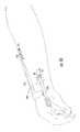
- the distal radius fractureis such that the major fracture line 15 associated with this type of injury generally occurs just above or proximal to the articular joint surface 11 of the distal radius at the wrist about the metaphysis 12 .
- one common distal radius fracture typeseparates the shaft 13 of the radius 10 from the distal end portion of the bone. That is, the fracture line 15 defines a first major bone fragment 18 which is located above the fracture line 15 (the distal side) proximate the articular joint surface 11 and extends substantially medially (laterally) across the radius 10 in the metaphysis region.
- the fracturemay also produce smaller bone fragments or splinters along the fracture line.
- the distal end portion of the radiusmay be present as multiple (vertically and/or horizontally oriented) fragments disrupting the articular joint surface itself. This latter type of Colles fracture is known as a comminuted intraarticular fracture (not shown).
- FIG. 1illustrates the fracture line 15 in the radius 10 as a substantially horizontal line which produces an upper or distal fracture fragment 18 as a substantially unitary fragment.
- FIG. 2illustrates a fracture line 15 in the radius 10 which is offset from a horizontal axis.
- FIG. 2illustrates a loss of radial inclination (in degrees) and a shortened length in the skeletal length line (shown with respect to a neutral length line “L”) which can occur after a fracture in the distal radius. That is, even healed, these types of fractures may cause shortening or collapse of the bone structure relative to the original skeletal length line. This, in turn, can result in deformity and pain.
- External fixation devicesare those that stabilize a fracture through the use of percutaneous pins which typically affix one or more bone portions to an external (anchoring or stabilizing) device.
- Internal fixation devicesare those devices which are configured to reside entirely within the subject (internal to the body).
- Percutaneous pinscan be used alone, without anchoring devices, for fixation of Colles type fractures.
- the use of external deviceshas conventionally been thought to be particularly indicated in cases of bone loss to preserve skeletal length as noted, for example, in U.S. Pat. No. 5,571,103 to Bailey at col. 1, lines 35–43. However, such devices can be bulky, cumbersome, and or invasive to the user or patient. Further, the external fixation devices may not be suitable for use in soft osteoporotic bone.
- the present inventionprovides methods and devices for treating fractures in or adjacent the wrist and distal forearm.
- the present inventionis particularly useful for stabilizing and treating distal radius fractures of a patient.
- the devices and methods of the present inventionemploys an intramedullary interlocking fixation rod (i.e, it interlocks the distal and proximal fracture fragments together) to stabilize the skeletal structure in a manner which can inhibit the amount of collapse or loss in skeletal length exhibited by a patient with a distal radius fracture.
- the devices and methods of the present inventionmay be especially useful for treating distal radius fractures in subjects with osteoporosis.
- One aspect of the inventionis a method for treating a distal radius fracture of a patient comprising the use of an internal fixation rod.
- the radiusanatomically has an articular joint surface, a metaphysis region, a shaft portion and a medullary canal associated therewith.
- the distal radius fracturehas a fracture line which divides the radius into a distal fracture fragment portion and a proximal fracture fragment portion.
- the distal fragment portionincludes the distal end of the radius proximate the articular joint surface, and the distal portion of the fracture has a width thereacross.
- the methodcomprises the steps of: (a) installing an elongated rod having opposing proximal and distal portions into the medullary canal of the patient such that the proximal portion of the rod resides above the fracture line (closer to the elbow) and the distal portion of the rod resides below the fracture line (closer to the hand); (b) securing a distal fixation member to the elongated rod and into the distal end portion of the radius at a location which is below the fracture line such that the distal fixation member extends internal of the patient substantially laterally across a portion of the width of the distal fracture fragment; and (c) anchoring the elongated rod inside the medullary canal of the radius at a location which is above (distal to) the fracture line.
- Another aspect of the present inventionis an internal fixation device for treating or repairing distal radius fractures having a fracture line forming distal and proximal fracture fragments.
- the radiusis anatomically configured with a distal articular joint surface, a metaphysis region, a shaft, and a medullary canal.
- the anatomic position of the handis palm forward or front such that the medial orientation is next to the body (fifth finger or ulna side of hand) and the lateral orientation is away from the body (thumb or radial side).
- the distal portion of the radiushas a width which extends across (a major portion of) the arm from the medial side to the lateral side.
- the deviceincludes an elongated fixation rod having opposing proximal and distal portions.
- the distal portionincludes a head with a laterally extending distal aperture formed therein, and the proximal portion comprises at least one proximal aperture formed therein.
- the elongated fixation rod proximal portionis sized and configured such that, in position, it resides in the shaft inside a portion of the medullary canal of the radius of a patient.
- the devicealso includes a distal fixation member configured to enter the distal aperture and attach to the rod and the distal fracture fragment to hold the distal portion of the rod to the distal fracture fragment.
- the devicefurther includes at least one proximal fixation member, a respective one for each of the at least one proximal apertures.
- the proximal fixation memberis configured to secure the lower portion of the fixation rod to the radius at a position which is distal to the fracture line. In position, the elongated fixation rod is configured to reside within the radius, and the distal fixation member and the at least one proximal fixation member are configured to reside internal of the body of the patient.
- the elongated fixation rodhas a curvilinear profile.
- the curvilinear profileincludes a distal curve portion at the distal portion of the device.
- the distal curve portionis adapted to accommodate the radial styloid region of the radius proximate the articular joint surface.
- the rodcan also be provided as a plurality of segments matable or attachable. In one embodiment an intermediate segment can be provided in different lengths to allow for the adjustment of length according to a patient's anatomical considerations.
- the rodcan be a unitary body provided in a number of standard sizes preferably statistically representative of the treatment population.
- FIG. 1is an anterior-posterior view of a distal radius fracture illustrating a fracture line proximate the articular joint surface.
- FIG. 2is an anterior-posterior view of a distal radius fracture similar to that shown in FIG. 1 . This figure illustrates an alternatively configured fracture line proximate the articular joint surface.
- FIG. 3Ais an anterior-posterior view of an intramedullary fixation rod attached to the radius for treating a distal radius fracture according to an embodiment of the present invention.
- FIG. 3Bis an exploded view of the distal fixation attachment member shown inserted into the fixation rod in FIG. 3A according to one embodiment of the present invention.
- FIG. 4is a front schematic view of the distal fixation rod of FIG. 3A in position as an internal fixation device held within the body of the patient according to one embodiment of the present invention.
- FIG. 5Ais a lateral view of an intramedullary rod configured to interlock or affix the bone fragments of a distal radius fracture according to one embodiment of the present invention.
- FIG. 5Bis a cross-sectional view of the rod shown in FIG. 5A taken along line 5 B– 5 B.
- FIG. 6is a perspective view of an intramedullary fixation device according to one embodiment of the present invention.
- FIG. 7is a side view (shown oriented anterior to posterior) of an alternate embodiment of an intramedullary system according to the present invention.
- FIG. 8is a side view (shown oriented anterior to posterior) of another embodiment of an intramedullary system according to the present invention.
- FIGS. 9Ais a front anterior-posterior view of an alternate embodiment of a distal fixation rod according to the present invention.
- FIG. 9Bis an exploded view of the linked or multi-segment rod shown in FIG. 9A .
- FIG. 9Cis a front view of a set of intermediate rod segments according to an embodiment of the present invention.
- FIG. 10is a schematic side view of an intramedullary system with an external detachable positioning guide according to an embodiment of the present invention.
- FIG. 11is a block diagram of the steps of treating a distal radius fracture according to one embodiment of the present invention.
- FIG. 12is perspective view of the arm of a patient illustrating a sigmoid or longitudinal incision over the radial styloid area.
- FIG. 13is an enlarged schematic view of the incision site in the patient shown in FIG. 12 to illustrate preparation of the site for positioning intramedullary fixation rods for distal radius fractures according to an embodiment of the present invention.
- FIG. 14is an enlarged schematic view of the incision site shown in FIG. 13 illustrating that a small bone window may be made or formed into the radius such that it extends across the fracture site according to the present invention.
- FIGS. 15Ais an anterior-posterior view of the bone window shown in FIG. 14 .
- FIG. 15Bis a schematic view of the prepared bone site shown in FIG. 15A illustrating the use of a sound or broach instrument which is sized and configured to be inserted into the intramedullary canal of the radius to determine size and/or open or prepare the canal to receive a fixation rod according to an embodiment of the present invention.
- FIG. 16is a top anterior-posterior view of an intramedullary fixation rod assembled to a rod driver and screw attachment guide according to one embodiment of the present invention.
- FIG. 17is a side (lateral) view of the device shown in FIG. 16 .
- FIG. 18is a side of the device shown in FIGS. 16 and 17 showing the device in position in the patient.
- FIG. 19is a top anterior-posterior view of the device shown in position in FIG. 18 .
- FIG. 20is a schematic view of the fixation rod in position in the subject according to an embodiment of the present invention.
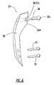
- the intramedullary fixation device 25includes an elongated axially extending rod 26 with a distal portion 27 and a proximal portion 28 .
- the device 25also includes a distal fixation member 30 and at least one proximal fixation member 35 (shown as two proximal fixation members 35 a , 35 b ).
- the rod 26includes a head 26 h at the distal end portion 27 of the rod 26 .
- a distal aperture 30 ais formed into the head 26 h of the distal portion such that it extends across the width of the rod 26 .
- the distal fixation member 30is configured to enter and extend through and beyond the distal aperture 30 a to engage with the distal fracture fragment 18 and secure the rod 26 and the distal fracture fragment 18 theretogether.
- the distal fixation member 30is sized to extend across a major portion of the width of the distal fracture fragment 18 . More preferably, the distal fixation member 30 is sized with a length which is sufficient to extend across substantially all of the fracture fragment 18 so as to provide support for the radial, center, and ulna aspects of the distal fracture fragment 18 (the ulna aspect being the part of the fracture fragment adjacent or proximate the ulna 14 while the radial aspect being the portion of the fracture fragment on the opposing side of the view shown in FIG. 3A and the center aspect being the portion in between).
- FIG. 3Billustrates the distal fixation member 30 apart from the rod 26 .
- the distal fixation member 30can be configured as any suitable attachment means to secure the distal fracture fragment 18 to the rod 26 , while also providing lateral structural reinforcement.
- the attachment meanscan be one or more of a pin, nail, threaded or partially threaded member such as a screw, or a combination of the above.
- FIG. 3Billustrates the distal fixation member 30 as having, in serial order, from one end to the other, a head portion 30 h , a threaded portion 30 th , and a pin portion 30 p.
- the head of the distal fixation member 30 hextends beyond the edge of the body of the rod 26 .
- the aperture 25 acan be configured (such as with a countersunk or recessed portion configured with a depth sufficient to receive the head 30 h therein) such that upon assembly, the distal fixation member head 30 h is substantially flush or recessed with the outer contour or profile of the rod 26 .
- FIG. 3Aalso illustrates that, in position in the patient, the distal fixation member 30 is preferably configured to directly abut the outer surface of the rod 26 .
- FIG. 6is a perspective view of one embodiment of the intramedullary fixation device 25 . This embodiment shows that the rod 26 is configured as a unitary body with a recess to receive the head 30 h of the distal fixation member 30 .
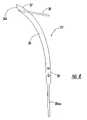
- the rod 26is configured with a profile 26 p which is curvilinear when viewed from the anterior-posterior view, as shown, for example, in FIGS. 3A and 4 .
- the proximal portion of the rod 28is substantially linear and is configured to axially extend within the medullary canal of the patient in the radial shaft.
- the rod 26approaches the metaphysis region ( 12 , FIG. 1 ) it gradually curves from the substantially linear axial extending portion so as to position the distal end 27 e of the rod 26 proximate the radial styloid region of the distal radius.
- the rod 26is configured to follow the contour line of the radius as it transitions from the proximal portion 28 having a substantially linear contour in the shaft region to the distal portion 27 which has a curvilinear or slight arcuately contoured shape proximate the metaphysis region.
- FIGS. 3A and 4also illustrate that the head 26 h of the rod 26 is preferably configured with a body which has an increased perimeter or area size with respect to the proximal 28 portion of the rod 26 . It is also preferred that the distal end of the head 26 h be beveled or inclined 27 i . As shown, the tip or end of the head 26 h slopes downwardly from the side surface adjacent the radial portion toward the ulna aspect of the fracture fragment 18 .
- the distal aperture 30 abe formed in the rod 26 such that it allows the distal fixation member 30 to extend therethrough and reside at a position which is angularly offset from the axial axis.
- the axial axisis coincident with the centerline of the proximal portion of the rod (indicated by the letter “a” in FIG. 3A ).
- the distal fixation member 30extends at a position which is less than about ninety degrees, and preferably between about 10 degrees to less than about 90 degrees, away from the axial axis, such that it is approximately in-line with the articular surface.
- the head 26 h of the rod 26can buttress the distal radius region and increase the structural effectiveness of the rod.
- the head 26 hcan reinforce or positively affect the structural integrity of the device to help support the radial styloid region of the distal fracture fragment.
- FIG. 3Aillustrates the use of two similarly sized proximal fixation members 35 a , 35 b , respectively, while FIG. 4 illustrates the use of one 35 .
- the proximal fixation members 35 a , 35 bare respective self-tapping screws positioned on the rod 26 such that they are proximate to each other.
- proximal fixation members 35 and corresponding apertures 25 aare primarily used to inhibit shortening of the skeletal structure. As shown in FIG.
- the proximal fixation member 35transversely extends in serial order, through a portion of the radius shaft, through a corresponding proximal receiving aperture 25 a formed in the rod 26 , and then into an opposing portion of the radius shaft to thereby secure or locate and hold the proximal portion of the rod 25 relative to the radius, the proximal fixation member having a length and opposing ends sized and configured accordingly 36 , 38 .
- FIG. 4schematically illustrates the preferred post-operative position of the intramedullary fixation device 25 in the patient. That is, post-operatively in position in the patient, the rod 26 and distal and proximal fixation members 30 , 35 are held within the body of the subject such that the device 25 is an internal fixation device and is devoid of externally located coupling or fixation members.
- the rod 26is installed into the medullary canal of the patient such that the distal portion 27 of the rod 26 resides distal to the fracture line 15 (but substantially within the distal radius, preferably so as to reside proximal to the articular joint surface 11 ) and the bottom or proximal portion 28 of the rod 26 extends through and resides proximal to the fracture line 15 .
- the distal fixation member 30is secured to the rod 26 and to the distal end portion of the radius at a location which is distal to the fracture line 15 in the metaphysis region of the distal radius.
- distal fixation member 30extends (to reside internal of the body of the patient) substantially transversely across a portion of the width of the distal fracture fragment 18 .
- the device 25may not be preferred for use with comminuted distal radius fractures.
- the rod 26In position, the rod 26 is configured such that it also extends through a portion of the medullary canal to terminate therein in the shaft region 13 of the radius 10 ( FIG. 1 ) (at a location which is proximally spaced away from the fracture line 15 ).
- the proximal portion 28 of the rod 26is anchored to the radius so as to reside inside the medullary canal of the radius.
- the proximal portion 28 of the rod 26is fixed in position relative to the shaft of the radius by the use of at least one pin, screw, or the like, as discussed above.
- FIG. 4also illustrates that the proximal end of the rod 28 e may be configured with a reduced cross-sectional size or tapered perimeter relative to the portion of the rod 26 thereabove to allow for ease of insertion into the patient.
- the proximal end of the device 28 eis substantially pointed.
- FIG. 5Aillustrates the rod 26 with a length “L”, a width “W” and a thickness “T”. It is envisioned that the rod 26 be provided or be made available for use in a plurality of lengths and widths so that the clinician can select the appropriate dimensions according to the particular anatomical needs of the patient. Preferably, for the distal radius fracture, the length of the rod 26 is between about 2–5 inches long, and more preferably between about 2.5 inches–4.0 inches long. It is also preferred that the width of the rod 26 be provided in an arrangement of incremental sizes. It is thought that suitable widths may be between about 2–8 mm in width and more preferably between about (2.5–4 mm) in width.
- the rod 26is held in the medullary canal of the radius of the patient.
- the lower or proximal portion 28 of the rod 26is preferably held substantially centrally in the shaft portion 13 of the radius 10 .
- the cross sectional shape of the rod 26is rectangular.
- the rod 26can be configured with other cross-sectional shapes, such as, but not limited to, circular, oval, square, triangular, and hexagon. It is also preferred that in designs with sharp edges, that the edges be radiused (“break edges”) to reduce the likelihood of stress fractures in the rod 26 (or in the bone adjacent the rod).
- break edgesto reduce the likelihood of stress fractures in the rod 26 (or in the bone adjacent the rod).
- the distal portion 27 of the rod 26may have a different cross-sectional shape and configuration from the proximal portion 28 of the rod 26 .
- the proximal portion 28 of the rod 26may have a circular shape with the addition of a ribbed portion on one side to inhibit rotation once in the intramedullary canal in the radius of the patient, while the distal portion 27 of the rod 26 can have an oval or rectangular shape (not shown).
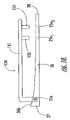
- FIG. 7illustrates another embodiment of an intramedullary fixation device 25 ′ according to the present invention.
- the rod 26is configured as first and second attachable segments or links 127 , 128 .
- the distal segment 127 of the rod 26is configured with the head of the rod 26 h while the proximal portion 128 is again configured to reside in the medullary canal of the radius shaft.
- the two segments 127 , 128are configured to align and mate together to define the rod 26 .
- a linking screw 120is inserted into a threaded aperture 120 a that it spans the first and second segments 127 , 128 when aligned.
- other attachment means or segment link configurationscan also be used, such as, but not limited to, bayonet type fittings, friction fit or threaded matable female/male components, and the like.
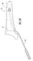
- FIG. 8illustrates another embodiment of an intramedullary fixation device 25 ′′ for the radius according to the present invention.
- the rod 26includes a proximal extension 28 ext.
- the proximal extension 28 extis tapered adjacent the proximal end portion 28 of the rod 26 .
- the extension 28 extis configured to reside in a more proximal portion of the radius shaft (away from the hand and closer to the elbow).
- This embodimentmay also be used in the absence of a distal radius fracture to treat proximal radius fractures.
- FIG. 8also illustrates that the distal fixation member 30 is oriented at about 45 degrees with respect to the axial axis. In any event, this configuration can allow for additional support in the shaft region of the radius (i.e., more proximal “purchase”).
- FIG. 9Aillustrates a rod 26 having a body with multiple segments or links 127 ′, 129 , 128 ′. As shown, in this embodiment, the rod 26 is defined by three segments, the distal segment 127 ′, an intermediate segment 129 , and a proximal segment 128 ′.
- FIG. 9Billustrates that, in this embodiment, the distal segment 127 ′ includes a protrusion 127 p ′ while the upper portion of the intermediate segment 129 includes a recess 129 r configured and sized to matably and/or securely receive the protrusion 127 p ′ therein.
- the proximal segment 128 ′includes a recess 128 r ′ formed therein configured to receive the intermediate segment protrusion 129 p therein.
- the segments 127 ′, 129 , 128 ′are sized and configured to be held together by a frictional fit of the interlocking or mating components, however, a biocompatible adhesive can also be used, as desired. Other attaching means can also be used to secure the segments together as will be appreciated by those of skill in the art.
- the protrusion 127 p ′can be threaded and configured to threadably engage with a threaded recess 129 r formed in the upper portion of the intermediate segment 129 .
- the proximal recess 128 r ′can be threaded and configured to threadably engage with the intermediate segment 129 p protrusion (which can be configured as a correspondingly configured male threaded component).
- the intermediate segment 129can be provided in an assortment of lengths to allow the rod 26 to be adjusted to a desired length according to the anatomical considerations of the patient.
- the intermediate segment 129can be a plurality of similarly sized or different, incrementally sized segments.
- the distal and proximal segments 127 ′, 128 ′can be provided as standardized-length components with the intermediate segment 129 providing an adjustable length.
- the cliniciancan custom fit the rod 26 at the use site. That is, the clinician can assess the patient and then determine the appropriate number or size of intermediate segments 129 to be used dependent on the length desired. This custom fit does not require the use of a preformed rod or a special order rod.
- the fitcan be carried out at the clinic, use, or installation site (proximate in time or contemporaneous with the treatment) to fit the number and size components together according to the needs of the patient.
- the distal and/or proximal segments 127 ′, 128 ′can also (or alternatively) be configured as or provided in different lengths.
- FIG. 10illustrates the use of an insertion or positioning guide 150 affixed to the distal end portion 27 of the rod 26 to allow for ease of insertion and placement into the patient.
- the guide 150includes an axially (or longitudinally) extending arm 151 which is configured to reside external of the body of the patient when the rod 26 is inserted into the intramedullary canal.
- the guide arm 151includes a visual locating means or visual indicia 153 , 155 which correspond to the proximal fixation apertures 25 a 1 , 25 a 2 to mark or identify the location of the internal apertures when the rod 26 is in a desired position in the patient. This allows the physician to be able to insert the proximal fixation members 35 a , 35 b in the proper location, aligned with the proximal apertures on the rod 26 held inside the patient.
- the visual indicia 153 , 155is preferably provided as laterally extending drill guides 153 , 155 which act to support a drill as it enters the patient and allows the drill to be inserted therein and guided to the desired location to provide bores into the bone on opposing sides of the rod 26 that are aligned with the rod proximal fixation apertures 25 a 1 , 25 a 2 .
- an incisionis made, such as a sigmoid or longitudinal incision over the radial styloid region of the patient's arm (adjacent to the base of the thumb).
- dissectionis carried down to the interval between the first and second dorsal compartments. Care should be taken so as not to injure the branches of the dorsal radial nerve.
- a small area of exposed boneis present between the first and second compartments (typically covered only by periosteum).
- a small bone window 16is preferably formed or made into the radius in this area. It may be appropriate to elevate the sheaths of the first and second dorsal compartments to facilitate adequate exposure for the bone window 16 .
- a substantially rectangular bone windowother shapes may also be used to provide access to the fracture region.
- a finder, sound, or broach-like device 175can be used prior to inserting the fixation rod 26 into the patient.
- the device 175is preferably semi-flexible to follow the contour of the canal in the radius.
- the device 175can be inserted through the bone window 16 and about the fracture region and used to determine the size and length of the intramedullary canal and/or to open the canal to a size suitable for receiving the fixation rod 26 .
- the soundsare available in length-and width calibrated sizes to help determine a size and length suitable for the fixation rod 26 according to the particular patient's intramedullary canal structure.
- the device 175can bore out or ream and/or define a desired entry and insertion passageway for the device 25 , 25 ′, 25 ′′ in advance of an actual installation into the patient.
- a fluoroscopic evaluation techniquecan be used to visualize the insertion of the device 175 and can help determine if the canal needs to be enlarged with a reamer or if a insertion path needs to be formed or shaped.
- FIG. 10illustrates one embodiment of a guide 150 .
- an applicator/handle or driver 150is attached to the rod 26 into the distal aperture 30 a ).
- the handle or driver 150then allows the physician to insert and guide the rod 26 into the desired location in the medullary canal in the radius.
- the proximal fixation members 3535 a , 35 b ) are ready for insertion.
- a small incisionor two is made at the proximal site of the radius.
- a drill or driveris inserted into the locator or drill guide holder 152 to align the entry of the proximal fixation member about the proximal aperture 25 and then force the threaded proximal fixation member(s) 35 ( 35 a , 35 b ) through the bone on the first (dorsal) side of the shaft of the radius, through the rod aperture 25 a 1 ( 25 a 2 ) and into the bone on the opposing (volar) side of the radial shaft.
- the proximal fixation member 35 ( 35 a , 35 b )extends through both sides of the bone.
- the distal fixation member 30is then inserted into the rod 26 through the distal aperture 30 a and attached to the distal radius ( FIG. 4 ).
- the distal fixation member 30is inserted into the radius at the fracture site or at an exposed site (created by removing a portion of the bone) to allow the head 30 h ( FIG. 3A ) of the distal fixation member 30 to be inserted into the rod 26 such that it rests directly against the body of the rod 26 (either protruding, flush, recessed therewith) and extends into the distal fracture fragment 18 .
- FIGS. 16 and 17illustrate an additional embodiment of an insertion guide 150 ′.
- the device 150 ′includes a rod driver 250 and an interlocking screw attachment guide 151 ′.
- the rod 26is attached to the rod driver 250 .
- the rod driver 250is attached to the fixation rod 26 via the distal aperture in the head of the rod 26 and an associated attachment member (shown as a screw 30 a ) and the interlocking screw attachment guide 151 ′ is attached to the rod driver 250 .
- the interlocking screw attachment guide 151 ′provides a screw guide alignment means such as screw or pin portals 153 , 155 to facilitate proper orientation and location of the proximal screws or pins into the patient and into the shaft 25 of the fixation rod 26 .
- the span of the screw attachment guide 151 ′is configured to provide the proper alignment position relative to the rod driver 250 .
- the rod driver 250 of the insertion guide 150 ′is used to direct the rod 26 into the intramedullary canal of the patient.
- the rod driver 250allows a physician to direct the fixation rod 26 into the radius through the bone window 16 .
- the position of the rod and the reduction of the fracturecan be verified by a fluoroscopy unit.
- a small incisioncan be made so that the proximal attachment guides 153 , 155 can be inserted therein. Traction may be appropriate to reduce the fracture at this time.
- the proximal attachment members 35 a , 35 bcan then be inserted into the radius after the region has been drilled and/or tapped.
- the proper positioning of the proximal attachment members 35 a , 35 bcan be verified by the fluoroscopy unit.
- the interlocking screw attachment guide 151 ′can then be removed from the patient and the rod driver 250 .
- the rod driver 250can be detached from the fixation rod 26 and the distal fixation member 30 can be inserted into the distal fragment and the fixation rod 26 as shown in FIG. 20 .
- Routine closureis performed on the incision sites and then, preferably, a long arm cast is applied to the patient.
- the typical healing processis about six weeks, during which time it is preferred that the treatment area be protected from undue stress and activity.
- a rod according to the present inventioncan be formed from a number of suitable biocompatible materials including titanium, stainless steel, and cobalt chrome. Because the radius is not a weight bearing extremity, strength is not as important in this type of fixation rod as it might be in other fixation rod applications.
- the rod 26comprises a material, at least on its exposed surfaces, which can inhibit the growth of undesirable microbial organisms.
- the rodis coated with a biocompatible antimicrobial solution or coating which can inhibit the growth of bacteria, yeast, mold, and fungus.
- One suitable materialmay be the antimicrobial silver zeolite based product available from HealthShield Technologies LLC of Wakefield, Mass. Another alternative is a Photolink® Infection Resistance antimicrobial coating or a hemocompatible coating from SurModics, Inc. of Eden Prairie, Minn. The coating may also include other bioactive ingredients (with or without the antimicrobial coating), such as antibiotics, and the like.
- One productis identified as LubriLASTTM lubricious coatings from AST of Billerica, Mass.
- a rod according to the present inventioncan be configured with a biocompatible lubricant or low-friction material to help reduce any discomfort associated with the insertion of the device into the body.
- Coatingswhich may be appropriate include coatings which promote lubricity, and wettability.
- a hydrophilic coatingwhich is applied as a thin (on the order of about 0.5–50 microns thick) layer which is chemically bonded with UV light over the external surface of the rod 26 .
- Hydrolene®available from SurModics, Inc., of Eden Prairie, Minn.
- Other similar productsare also available from the same source.
- the rod 26can be configured not only to provide the lubricious coating but to also include bioactive ingredients configured to provide sustained release of antibiotics, antimicrobial, and anti-restenosis agents, identified as LubriiLastTM from AST as noted above.
- FIG. 11illustrates the steps of a method for treating a fracture in the radius of a patient according to one embodiment of the present invention.
- An elongated axially extending rodis inserted into the intramedullary canal of the patient (Block 210 ).
- Proximal fixation membersare then secured to the rod to hold the rod in the intramedullary canal attached to the proximately located bone in the radius shaft (Block 220 ).
- a distal fixation memberis inserted into a distal portion of the rod such that it extends substantially medially or transversely across a distal portion of the radius (Block 230 ).
- a bone windowmay be formed into the radius to define an entry point for the rod (typically the window is formed into a small area of exposed bone which is present between the first and second compartments and covered only by periosteum) in the styloid region adjacent the two bone fragments.
- the internal intramedullary radius fixation devices and associated treatment methods of the instant inventioncan provide improved or alternative treatment options over those conventionally available.
- the devices and methods of the instant inventionmay inhibit the collapse in the skeletal structure along the fracture fragment region and may be useful for the osteoporotic patient.
- the devices of the instant inventioncan also provide increased structural integrity and/or strength when in position in the distal radius fracture fragment.
Landscapes
- Health & Medical Sciences (AREA)
- Surgery (AREA)
- Life Sciences & Earth Sciences (AREA)
- Orthopedic Medicine & Surgery (AREA)
- Biomedical Technology (AREA)
- Public Health (AREA)
- Veterinary Medicine (AREA)
- Engineering & Computer Science (AREA)
- Nuclear Medicine, Radiotherapy & Molecular Imaging (AREA)
- Heart & Thoracic Surgery (AREA)
- Medical Informatics (AREA)
- Molecular Biology (AREA)
- Animal Behavior & Ethology (AREA)
- General Health & Medical Sciences (AREA)
- Dentistry (AREA)
- Oral & Maxillofacial Surgery (AREA)
- Neurology (AREA)
- Surgical Instruments (AREA)
Abstract
Description
Claims (40)
Priority Applications (4)
| Application Number | Priority Date | Filing Date | Title |
|---|---|---|---|
| US10/377,255US7160302B2 (en) | 2000-09-22 | 2003-02-28 | Intramedullary interlocking fixation device for the distal radius |
| US11/381,227US8092453B2 (en) | 2000-09-22 | 2006-05-02 | Intramedullary interlocking fixation devices for the distal radius |
| US11/381,231US7713271B2 (en) | 2000-09-22 | 2006-05-02 | Intramedullary interlocking fixation devices for the distal radius |
| US12/391,459US8100910B2 (en) | 2000-09-22 | 2009-02-24 | Intramedullary interlocking fixation devices for the distal radius |
Applications Claiming Priority (2)
| Application Number | Priority Date | Filing Date | Title |
|---|---|---|---|
| US09/668,941US6527775B1 (en) | 2000-09-22 | 2000-09-22 | Intramedullary interlocking fixation device for the distal radius |
| US10/377,255US7160302B2 (en) | 2000-09-22 | 2003-02-28 | Intramedullary interlocking fixation device for the distal radius |
Related Parent Applications (1)
| Application Number | Title | Priority Date | Filing Date |
|---|---|---|---|
| US09/668,941ContinuationUS6527775B1 (en) | 2000-09-22 | 2000-09-22 | Intramedullary interlocking fixation device for the distal radius |
Related Child Applications (3)
| Application Number | Title | Priority Date | Filing Date |
|---|---|---|---|
| US11/381,231ContinuationUS7713271B2 (en) | 2000-09-22 | 2006-05-02 | Intramedullary interlocking fixation devices for the distal radius |
| US11/381,227ContinuationUS8092453B2 (en) | 2000-09-22 | 2006-05-02 | Intramedullary interlocking fixation devices for the distal radius |
| US11/381,227DivisionUS8092453B2 (en) | 2000-09-22 | 2006-05-02 | Intramedullary interlocking fixation devices for the distal radius |
Publications (2)
| Publication Number | Publication Date |
|---|---|
| US20040010255A1 US20040010255A1 (en) | 2004-01-15 |
| US7160302B2true US7160302B2 (en) | 2007-01-09 |
Family
ID=24684386
Family Applications (5)
| Application Number | Title | Priority Date | Filing Date |
|---|---|---|---|
| US09/668,941Expired - LifetimeUS6527775B1 (en) | 2000-09-22 | 2000-09-22 | Intramedullary interlocking fixation device for the distal radius |
| US10/377,255Expired - LifetimeUS7160302B2 (en) | 2000-09-22 | 2003-02-28 | Intramedullary interlocking fixation device for the distal radius |
| US11/381,227Expired - Fee RelatedUS8092453B2 (en) | 2000-09-22 | 2006-05-02 | Intramedullary interlocking fixation devices for the distal radius |
| US11/381,231Expired - Fee RelatedUS7713271B2 (en) | 2000-09-22 | 2006-05-02 | Intramedullary interlocking fixation devices for the distal radius |
| US12/391,459Expired - Fee RelatedUS8100910B2 (en) | 2000-09-22 | 2009-02-24 | Intramedullary interlocking fixation devices for the distal radius |
Family Applications Before (1)
| Application Number | Title | Priority Date | Filing Date |
|---|---|---|---|
| US09/668,941Expired - LifetimeUS6527775B1 (en) | 2000-09-22 | 2000-09-22 | Intramedullary interlocking fixation device for the distal radius |
Family Applications After (3)
| Application Number | Title | Priority Date | Filing Date |
|---|---|---|---|
| US11/381,227Expired - Fee RelatedUS8092453B2 (en) | 2000-09-22 | 2006-05-02 | Intramedullary interlocking fixation devices for the distal radius |
| US11/381,231Expired - Fee RelatedUS7713271B2 (en) | 2000-09-22 | 2006-05-02 | Intramedullary interlocking fixation devices for the distal radius |
| US12/391,459Expired - Fee RelatedUS8100910B2 (en) | 2000-09-22 | 2009-02-24 | Intramedullary interlocking fixation devices for the distal radius |
Country Status (3)
| Country | Link |
|---|---|
| US (5) | US6527775B1 (en) |
| AU (1) | AU2001290630A1 (en) |
| WO (1) | WO2002024088A2 (en) |
Cited By (46)
| Publication number | Priority date | Publication date | Assignee | Title |
|---|---|---|---|---|
| US20040111090A1 (en)* | 2002-10-03 | 2004-06-10 | The University Of North Carolina At Chapel Hill | Modification of percutaneous intrafocal plate system |
| US20060015101A1 (en)* | 2004-07-15 | 2006-01-19 | Wright Medical Technology, Inc. | Intramedullary fixation assembly and devices and methods for installing the same |
| US20060122613A1 (en)* | 2004-12-02 | 2006-06-08 | Kirsch John M | Fixator for a fractured bone |
| US20060264950A1 (en)* | 2005-05-18 | 2006-11-23 | Nelson Charles L | Minimally Invasive Actuable Bone Fixation Devices |
| US20070173835A1 (en)* | 2006-01-13 | 2007-07-26 | Medoff Robert J | Intramedullary implant for fracture fixation and method of using the same |
| US20080132896A1 (en)* | 2006-11-22 | 2008-06-05 | Sonoma Orthopedic Products, Inc. | Curved orthopedic tool |
| US20080140078A1 (en)* | 2006-11-22 | 2008-06-12 | Sonoma Orthopedic Products, Inc. | Surgical tools for use in deploying bone repair devices |
| US20080149115A1 (en)* | 2006-11-22 | 2008-06-26 | Sonoma Orthopedic Products, Inc. | Surgical station for orthopedic reconstruction surgery |
| US20080161805A1 (en)* | 2006-11-22 | 2008-07-03 | Sonoma Orthopedic Products, Inc. | Fracture fixation device, tools and methods |
| US20090157077A1 (en)* | 2007-12-17 | 2009-06-18 | Wright Medical Technology, Inc. | Guide assembly for intramedullary fixation and method of using the same |
| US20090292292A1 (en)* | 2004-07-15 | 2009-11-26 | Wright Medical Technology, Inc. | Guide assembly for intramedullary fixation and method of using the same |
| US20100121324A1 (en)* | 2008-06-24 | 2010-05-13 | Jeff Tyber | Fixation system, an intramedullary fixation assembly and method of use |
| US20100137863A1 (en)* | 2006-04-06 | 2010-06-03 | Halifax Biomedical Inc. | Intramedullary rod with vent |
| US20100234846A1 (en)* | 2009-03-13 | 2010-09-16 | Eglseder W Andrew | Intramedullary radial head locking pin implant |
| US20100256639A1 (en)* | 2008-06-24 | 2010-10-07 | Jeff Tyber | Fixation system, an intramedullary fixation assembly and method of use |
| US20100256638A1 (en)* | 2008-06-24 | 2010-10-07 | Jeff Tyber | Intraosseous intramedullary fixation assembly and method of use |
| US20100324556A1 (en)* | 2008-06-24 | 2010-12-23 | Jeff Tyber | Fixation system, an intramedullary fixation assembly and method of use |
| US20110118739A1 (en)* | 2008-06-24 | 2011-05-19 | Jeff Tyber | Intramedullary fixation assembly and method of use |
| US20110150962A1 (en)* | 2009-12-17 | 2011-06-23 | Stryker Trauma Gmbh | Therapeutic agent capsule for implants |
| US20110152863A1 (en)* | 2009-12-17 | 2011-06-23 | Stryker Trauma Gmbh | Encapsulated screw locking system |
| US20110213367A1 (en)* | 2008-06-24 | 2011-09-01 | Jeff Tyber | Intramedullary fixation screw, a fixation system, and method of fixation of the subtalar joint |
| US20110218585A1 (en)* | 2010-03-08 | 2011-09-08 | Krinke Todd A | Apparatus and methods for bone repair |
| US20110230884A1 (en)* | 2008-06-24 | 2011-09-22 | Adam Mantzaris | Hybrid intramedullary fixation assembly and method of use |
| US8287538B2 (en) | 2008-01-14 | 2012-10-16 | Conventus Orthopaedics, Inc. | Apparatus and methods for fracture repair |
| US8287539B2 (en) | 2005-05-18 | 2012-10-16 | Sonoma Orthopedic Products, Inc. | Fracture fixation device, tools and methods |
| US8591554B2 (en) | 2010-05-07 | 2013-11-26 | Osteomed Llc | System for treating bone fractures |
| US8668694B2 (en) | 2008-06-06 | 2014-03-11 | Steven M. Teeny | Bone fixation assemblies and methods of use |
| US8906022B2 (en) | 2010-03-08 | 2014-12-09 | Conventus Orthopaedics, Inc. | Apparatus and methods for securing a bone implant |
| US8961518B2 (en) | 2010-01-20 | 2015-02-24 | Conventus Orthopaedics, Inc. | Apparatus and methods for bone access and cavity preparation |
| US8961516B2 (en) | 2005-05-18 | 2015-02-24 | Sonoma Orthopedic Products, Inc. | Straight intramedullary fracture fixation devices and methods |
| US9060820B2 (en) | 2005-05-18 | 2015-06-23 | Sonoma Orthopedic Products, Inc. | Segmented intramedullary fracture fixation devices and methods |
| US9155574B2 (en) | 2006-05-17 | 2015-10-13 | Sonoma Orthopedic Products, Inc. | Bone fixation device, tools and methods |
| US9289220B2 (en) | 2008-06-24 | 2016-03-22 | Extremity Medical Llc | Intramedullary fixation assembly and method of use |
| US9597129B2 (en) | 2007-05-25 | 2017-03-21 | Zimmer Gmbh | Reinforced intramedullary nail |
| US9730739B2 (en) | 2010-01-15 | 2017-08-15 | Conventus Orthopaedics, Inc. | Rotary-rigid orthopaedic rod |
| US9770278B2 (en) | 2014-01-17 | 2017-09-26 | Arthrex, Inc. | Dual tip guide wire |
| US9814499B2 (en) | 2014-09-30 | 2017-11-14 | Arthrex, Inc. | Intramedullary fracture fixation devices and methods |
| US9833270B2 (en) | 2013-09-19 | 2017-12-05 | Mcginley Engineered Solutions, Llc | Variable angle blade plate system and method |
| US10022132B2 (en) | 2013-12-12 | 2018-07-17 | Conventus Orthopaedics, Inc. | Tissue displacement tools and methods |
| US10251682B2 (en) | 2017-03-22 | 2019-04-09 | DePuy Synthes Products, Inc. | Distal radius nail |
| US10258328B2 (en) | 2015-01-12 | 2019-04-16 | Extremity Medical, Llc | Fixation assembly and method of use |
| US10918426B2 (en) | 2017-07-04 | 2021-02-16 | Conventus Orthopaedics, Inc. | Apparatus and methods for treatment of a bone |
| US11051864B2 (en) | 2012-08-30 | 2021-07-06 | DePuy Synthes Products, Inc. | Intramedullary fixation assembly |
| US11426220B2 (en) | 2017-10-11 | 2022-08-30 | Howmedica Osteonics Corp. | Humeral fixation plate guides |
| US11596419B2 (en) | 2017-03-09 | 2023-03-07 | Flower Orthopedics Corporation | Plating depth gauge and countersink instrument |
| US12226133B2 (en) | 2017-04-06 | 2025-02-18 | Extremity Medical Llc | Orthopedic plate with modular peg and compression screw |
Families Citing this family (133)
| Publication number | Priority date | Publication date | Assignee | Title |
|---|---|---|---|---|
| US6893444B2 (en)* | 2000-02-01 | 2005-05-17 | Hand Innovations, Llc | Bone fracture fixation systems with both multidirectional and unidirectional stabilization pegs |
| US7695502B2 (en) | 2000-02-01 | 2010-04-13 | Depuy Products, Inc. | Bone stabilization system including plate having fixed-angle holes together with unidirectional locking screws and surgeon-directed locking screws |
| US6730090B2 (en) | 2000-02-01 | 2004-05-04 | Hand Innovations, Inc. | Fixation device for metaphyseal long bone fractures |
| US20060041260A1 (en)* | 2000-02-01 | 2006-02-23 | Orbay Jorge L | Fixation system with plate having holes with divergent axes and multidirectional fixators for use therethrough |
| US20040153073A1 (en)* | 2000-02-01 | 2004-08-05 | Hand Innovations, Inc. | Orthopedic fixation system including plate element with threaded holes having divergent axes |
| US7857838B2 (en)* | 2003-03-27 | 2010-12-28 | Depuy Products, Inc. | Anatomical distal radius fracture fixation plate |
| US6767351B2 (en)* | 2000-02-01 | 2004-07-27 | Hand Innovations, Inc. | Fixation system with multidirectional stabilization pegs |
| US6866665B2 (en)* | 2003-03-27 | 2005-03-15 | Hand Innovations, Llc | Bone fracture fixation system with subchondral and articular surface support |
| US6706046B2 (en)* | 2000-02-01 | 2004-03-16 | Hand Innovations, Inc. | Intramedullary fixation device for metaphyseal long bone fractures and methods of using the same |
| US7282053B2 (en)* | 2003-03-27 | 2007-10-16 | Depuy Products, Inc. | Method of using fracture fixation plate for performing osteotomy |
| US8920509B2 (en) | 2000-04-10 | 2014-12-30 | Biomet Manufacturing, Llc | Modular radial head prosthesis |
| US8535382B2 (en) | 2000-04-10 | 2013-09-17 | Biomet Manufacturing, Llc | Modular radial head prostheses |
| US8114163B2 (en) | 2000-04-10 | 2012-02-14 | Biomet Manufacturing Corp. | Method and apparatus for adjusting height and angle for a radial head |
| US6527775B1 (en) | 2000-09-22 | 2003-03-04 | Piper Medical, Inc. | Intramedullary interlocking fixation device for the distal radius |
| US7942877B2 (en)* | 2001-02-12 | 2011-05-17 | Medoff Robert J | Guide system and associated method for installing an implant device adapted to apply compression across a fracture site |
| US20050234458A1 (en)* | 2004-04-19 | 2005-10-20 | Huebner Randall J | Expanded stabilization of bones |
| US7717945B2 (en)* | 2002-07-22 | 2010-05-18 | Acumed Llc | Orthopedic systems |
| US20050240187A1 (en)* | 2004-04-22 | 2005-10-27 | Huebner Randall J | Expanded fixation of bones |
| US20070055249A1 (en)* | 2003-06-20 | 2007-03-08 | Jensen David G | Bone plates with intraoperatively tapped apertures |
| US7537604B2 (en)* | 2002-11-19 | 2009-05-26 | Acumed Llc | Bone plates with slots |
| US7326212B2 (en)* | 2002-11-19 | 2008-02-05 | Acumed Llc | Bone plates with reference marks |
| US6793659B2 (en)* | 2001-10-12 | 2004-09-21 | Regents Of The University Of Minnesota | Intramedullary rod for wrist fixation |
| JP2005516724A (en)* | 2002-02-11 | 2005-06-09 | スミス アンド ネフュー インコーポレーテッド | Image guided fracture reduction |
| US7938850B2 (en)* | 2002-05-30 | 2011-05-10 | Depuy Products, Inc. | Nail plate |
| US20060149257A1 (en)* | 2002-05-30 | 2006-07-06 | Orbay Jorge L | Fracture fixation device |
| US20040116930A1 (en)* | 2002-06-10 | 2004-06-17 | O'driscoll Shawn W. | Bone plates |
| US20050171544A1 (en)* | 2004-02-02 | 2005-08-04 | Acumed Llc | Bone plate with toothed aperture |
| CN1309352C (en) | 2002-07-22 | 2007-04-11 | 精密医疗责任有限公司 | Bone fusion system |
| AU2003294342A1 (en)* | 2002-11-19 | 2004-06-15 | Acumed Llc | Guide system for bone-repair devices |
| AU2003294414B2 (en)* | 2002-11-19 | 2009-03-12 | Acumed Llc | Deformable bone plates |
| US20050187551A1 (en)* | 2002-12-02 | 2005-08-25 | Orbay Jorge L. | Bone plate system with bone screws fixed by secondary compression |
| US7123962B2 (en)* | 2002-12-02 | 2006-10-17 | Cardiac Pacemakers, Inc. | Phonocardiographic image-based atrioventricular delay optimization |
| US7780664B2 (en)* | 2002-12-10 | 2010-08-24 | Depuy Products, Inc. | Endosteal nail |
| US7250053B2 (en)* | 2003-03-27 | 2007-07-31 | Depuy Products, Inc. | Low profile distal radius fracture fixation plate |
| US7635381B2 (en)* | 2003-03-27 | 2009-12-22 | Depuy Products, Inc. | Anatomical distal radius fracture fixation plate with fixed-angle K-wire holes defining a three-dimensional surface |
| US20040193155A1 (en)* | 2003-03-27 | 2004-09-30 | Hand Innovations, Inc. | Fracture fixation plate with particular plate hole and fastener engagement and methods of using the same |
| US7294130B2 (en)* | 2003-03-27 | 2007-11-13 | Depuy Products, Inc. | Distal radius fracture fixation plate having K-wire hole structured to fix a K-wire in one dimension relative to the plate |
| WO2004112587A2 (en) | 2003-06-20 | 2004-12-29 | Acumed Llc | Bone plates with intraoperatively tapped apertures |
| US20050131413A1 (en)* | 2003-06-20 | 2005-06-16 | O'driscoll Shawn W. | Bone plate with interference fit screw |
| US7635365B2 (en) | 2003-08-28 | 2009-12-22 | Ellis Thomas J | Bone plates |
| US7852919B2 (en)* | 2003-09-07 | 2010-12-14 | Microsoft Corporation | Field start code for entry point frames with predicted first field |
| US7799030B2 (en)* | 2003-09-08 | 2010-09-21 | Smith & Nephew, Inc. | Orthopaedic plate and screw assembly |
| US20050055024A1 (en)* | 2003-09-08 | 2005-03-10 | James Anthony H. | Orthopaedic implant and screw assembly |
| US7780667B2 (en)* | 2003-09-08 | 2010-08-24 | Smith & Nephew, Inc. | Orthopaedic plate and screw assembly |
| US7267678B2 (en)* | 2003-09-30 | 2007-09-11 | Robert J. Medoff | Intramedullary implant for fracture fixation |
| US6926720B2 (en)* | 2003-10-15 | 2005-08-09 | Hand Innovations, Llc | Jig assembly for implantation of a fracture fixation device |
| US7299561B2 (en)* | 2003-10-15 | 2007-11-27 | Depuy Products, Inc. | Gauge system for use in implantation of a fracture fixation device |
| US20050107793A1 (en)* | 2003-11-14 | 2005-05-19 | Manderson Easton L. | Surgical intramedullary implant with improved locking for fixation of fractured bone segments |
| AU300211S (en)* | 2004-01-19 | 2004-11-12 | Synthes Gmbh | Surgical aiming device |
| CA113691S (en)* | 2004-01-19 | 2007-05-28 | Synthes Gmbh | Base for a surgical aiming device |
| WO2005102193A2 (en)* | 2004-04-19 | 2005-11-03 | Acumed, Llc | Placement of fasteners into bone |
| US20060036248A1 (en)* | 2004-07-01 | 2006-02-16 | Ferrante Joseph M | Fixation elements |
| US20180228621A1 (en) | 2004-08-09 | 2018-08-16 | Mark A. Reiley | Apparatus, systems, and methods for the fixation or fusion of bone |
| US8414648B2 (en) | 2004-08-09 | 2013-04-09 | Si-Bone Inc. | Apparatus, systems, and methods for achieving trans-iliac lumbar fusion |
| US8470004B2 (en) | 2004-08-09 | 2013-06-25 | Si-Bone Inc. | Apparatus, systems, and methods for stabilizing a spondylolisthesis |
| US9662158B2 (en)* | 2004-08-09 | 2017-05-30 | Si-Bone Inc. | Systems and methods for the fixation or fusion of bone at or near a sacroiliac joint |
| US20060036251A1 (en) | 2004-08-09 | 2006-02-16 | Reiley Mark A | Systems and methods for the fixation or fusion of bone |
| US20070156241A1 (en)* | 2004-08-09 | 2007-07-05 | Reiley Mark A | Systems and methods for the fixation or fusion of bone |
| US8444693B2 (en) | 2004-08-09 | 2013-05-21 | Si-Bone Inc. | Apparatus, systems, and methods for achieving lumbar facet fusion |
| US8425570B2 (en) | 2004-08-09 | 2013-04-23 | Si-Bone Inc. | Apparatus, systems, and methods for achieving anterior lumbar interbody fusion |
| US9949843B2 (en) | 2004-08-09 | 2018-04-24 | Si-Bone Inc. | Apparatus, systems, and methods for the fixation or fusion of bone |
| US8388667B2 (en) | 2004-08-09 | 2013-03-05 | Si-Bone, Inc. | Systems and methods for the fixation or fusion of bone using compressive implants |
| US8394130B2 (en) | 2005-03-17 | 2013-03-12 | Biomet C.V. | Modular fracture fixation system |
| EP1827271B1 (en)* | 2004-12-23 | 2009-12-02 | Hans Ulrich Stäubli | Bone fixing device |
| CA2596266C (en)* | 2005-01-28 | 2015-03-31 | Depuy Products, Inc. | Nail plate system |
| US7410488B2 (en) | 2005-02-18 | 2008-08-12 | Smith & Nephew, Inc. | Hindfoot nail |
| US20060235383A1 (en)* | 2005-03-07 | 2006-10-19 | Shane Hollawell | External fixator |
| CN1332634C (en)* | 2005-07-14 | 2007-08-22 | 中国人民解放军南京军区南京总医院 | Interlocking intramedullary nail having photoelectric positioning system |
| US7905909B2 (en)* | 2005-09-19 | 2011-03-15 | Depuy Products, Inc. | Bone stabilization system including multi-directional threaded fixation element |
| US20070083202A1 (en)* | 2005-09-20 | 2007-04-12 | Donald Eli Running | Intramedullary bone plate with sheath |
| US7691105B2 (en)* | 2005-09-26 | 2010-04-06 | Depuy Spine, Inc. | Tissue augmentation, stabilization and regeneration technique |
| US20080249580A1 (en)* | 2005-09-28 | 2008-10-09 | Smith & Nephew, Inc. | Methods and Instruments of Reducing a Fracture |
| US20070155271A1 (en)* | 2005-12-30 | 2007-07-05 | Touzov Igor V | Heat conductive textile and method producing thereof |
| US7686808B2 (en)* | 2006-01-27 | 2010-03-30 | Depuy Products, Inc. | Fracture fixation device and implantation jig therefor |
| US20070179613A1 (en)* | 2006-01-30 | 2007-08-02 | Sdgi Holdings, Inc. | Passive lubricating prosthetic joint |
| US8740903B2 (en)* | 2006-02-09 | 2014-06-03 | DePuy Synthes Products, LLC | Method and apparatus for bone fracture fixation |
| DE102007008184A1 (en)* | 2007-02-13 | 2008-08-14 | Aesculap Ag & Co. Kg | Implant for fixing together two bone parts of the sternum comprises a one-piece bearing element and an anti-adhesion layer on the surface for preventing post-operative tissue adhesion |
| US7722611B2 (en)* | 2007-03-05 | 2010-05-25 | Depuy Products, Inc. | Method of treating a clavicle fracture |
| US8277448B2 (en)* | 2007-03-07 | 2012-10-02 | Wright Medical Technology, Inc. | External fixation |
| US7918853B2 (en)* | 2007-03-20 | 2011-04-05 | Smith & Nephew, Inc. | Orthopaedic plate and screw assembly |
| AU2008228710A1 (en)* | 2007-03-22 | 2008-09-25 | Novalign Orthopaedics, Inc. | Segmented intramedullary structure |
| USD601701S1 (en)* | 2008-06-13 | 2009-10-06 | Yechiel Gotfried | Surgical instrument |
| US20120022534A1 (en)* | 2008-09-17 | 2012-01-26 | Skeletal Dynamics Llc | Intramedullary arthrodesis nail and method of use |
| US9095440B2 (en)* | 2008-09-17 | 2015-08-04 | Skeletal Dynamics, Llc | Intramedullary arthrodesis nail and method of use |
| US9237910B2 (en) | 2012-01-26 | 2016-01-19 | Acute Innovations Llc | Clip for rib stabilization |
| US12285197B2 (en) | 2008-10-10 | 2025-04-29 | Acumed Llc | Bone fixation system with opposed mounting portions |
| ES2524076T3 (en) | 2008-10-15 | 2014-12-04 | Zimmer Gmbh | Intramedullary nail |
| US9622798B2 (en)* | 2009-02-17 | 2017-04-18 | Gregory Merrell | Intramedullary compression rod |
| US8834469B2 (en) | 2009-06-30 | 2014-09-16 | Smith & Nephew, Inc. | Orthopaedic implant and fastener assembly |
| US8449544B2 (en) | 2009-06-30 | 2013-05-28 | Smith & Nephew, Inc. | Orthopaedic implant and fastener assembly |
| US8568417B2 (en) | 2009-12-18 | 2013-10-29 | Charles River Engineering Solutions And Technologies, Llc | Articulating tool and methods of using |
| WO2011136747A1 (en)* | 2010-04-27 | 2011-11-03 | Tst Rkor Ve Tibbi Aletler Sanayi Ve Ticaret Limited Şirket | Radius intramedullar locking nail |
| GB201105243D0 (en) | 2011-03-29 | 2011-05-11 | Depuy Ireland | An implant |
| WO2012174258A2 (en) | 2011-06-14 | 2012-12-20 | Amit Gupta | Intramedullary system for managing a bone fracture |
| WO2013049849A2 (en) | 2011-09-30 | 2013-04-04 | Acute Innovations, Llc, An Oregon Limited Liability Company | Bone fixation system with opposed mounting portions |
| US10363140B2 (en) | 2012-03-09 | 2019-07-30 | Si-Bone Inc. | Systems, device, and methods for joint fusion |
| US9044321B2 (en) | 2012-03-09 | 2015-06-02 | Si-Bone Inc. | Integrated implant |
| US8668692B1 (en) | 2012-05-01 | 2014-03-11 | Eric M. Lindvall | Intramedullary linkage device, system, and method for implantation |
| EP3818947B1 (en) | 2012-05-04 | 2023-08-30 | SI-Bone, Inc. | Fenestrated implant |
| US9398928B2 (en) | 2012-09-28 | 2016-07-26 | DePuy Synthes Products, Inc. | Adjustable height arthroplasty plate |
| EP2732783B1 (en)* | 2012-11-14 | 2016-04-27 | Biedermann Technologies GmbH & Co. KG | Bone nail for the heel |
| WO2014145902A1 (en) | 2013-03-15 | 2014-09-18 | Si-Bone Inc. | Implants for spinal fixation or fusion |
| US9408635B2 (en) | 2013-03-15 | 2016-08-09 | Wright Medical Technology, Inc. | External fixation |
| WO2015017074A1 (en)* | 2013-07-02 | 2015-02-05 | Cmarr Enterprises | Curved tibiotalar fusion nail and method of use |
| US9089375B2 (en) | 2013-10-12 | 2015-07-28 | Interfix, Llc | Combined intramedullary and extramedullary surgical aiming system and method |
| US11147688B2 (en) | 2013-10-15 | 2021-10-19 | Si-Bone Inc. | Implant placement |
| US9839448B2 (en) | 2013-10-15 | 2017-12-12 | Si-Bone Inc. | Implant placement |
| US10543026B2 (en) | 2014-04-21 | 2020-01-28 | The General Hospital Corporation | Fracture fixation device having clip for stabilizing intramedullary nail |
| US10258381B2 (en)* | 2014-07-03 | 2019-04-16 | Stryker European Holdings I, Llc | Conical end cap for intramedullary nail |
| EP3164093B1 (en) | 2014-07-03 | 2024-02-14 | Acumed LLC | Bone plate with movable joint |
| JP6542362B2 (en) | 2014-09-18 | 2019-07-10 | エスアイ−ボーン・インコーポレイテッドSi−Bone, Inc. | Matrix implant |
| US10166033B2 (en) | 2014-09-18 | 2019-01-01 | Si-Bone Inc. | Implants for bone fixation or fusion |
| US10376206B2 (en) | 2015-04-01 | 2019-08-13 | Si-Bone Inc. | Neuromonitoring systems and methods for bone fixation or fusion procedures |
| WO2017069718A1 (en)* | 2015-10-21 | 2017-04-27 | Tst Rakor Ve Tibbi̇ Aletler Sanayi̇ Ve Ti̇caret Li̇mi̇ted Şi̇rketi̇ | Ulna internal safe locking nail |
| US10561449B2 (en) | 2015-10-21 | 2020-02-18 | Tst Rakor Ve Tibbi Aletler Sanayi Ve Ticaret Limited Sirketi | Humerus internal safe locking nail |
| RU2601850C1 (en)* | 2015-10-22 | 2016-11-10 | Михаил Васильевич Гилев | Method of open reduction and osteosynthesis of distal radius fractures |
| RU2641379C1 (en)* | 2017-02-01 | 2018-01-17 | Федеральное государственное бюджетное образовательное учреждение высшего образования "Уральский государственный медицинский университет" Министерства здравоохранения Российской Федерации (ФГБОУ ВО УГМУ Минздрава России) | Method for arthroplasty of distal department of radial bone with multifragment joint fractures of distal department of radial bone |
| US11116519B2 (en) | 2017-09-26 | 2021-09-14 | Si-Bone Inc. | Systems and methods for decorticating the sacroiliac joint |
| US10639050B2 (en) | 2017-10-02 | 2020-05-05 | Robin Kamal | System and method for interosseous ligament reconstruction |
| US10881436B2 (en) | 2017-10-27 | 2021-01-05 | Wright Medical Technology, Inc. | Implant with intramedullary portion and offset extramedullary portion |
| US10610270B2 (en) | 2018-01-15 | 2020-04-07 | Glw, Inc. | Hybrid intramedullary rods |
| US10932828B2 (en) | 2018-01-25 | 2021-03-02 | Advanced Orthopaedic Solutions, Inc. | Bone nail |
| ES3011907T3 (en) | 2018-03-28 | 2025-04-08 | Si Bone Inc | Threaded implants for use across bone segments |
| CN108682001A (en)* | 2018-03-30 | 2018-10-19 | 深圳市深图医学影像设备有限公司 | The measurement method and device of bone density |
| EP3920817A1 (en)* | 2019-02-08 | 2021-12-15 | Disrad Ag | Distal radius fracture fixation device |
| EP4613244A2 (en) | 2019-02-14 | 2025-09-10 | SI-Bone Inc. | Implants for spinal fixation and or fusion |
| US11369419B2 (en) | 2019-02-14 | 2022-06-28 | Si-Bone Inc. | Implants for spinal fixation and or fusion |
| BE1027082B1 (en)* | 2019-02-27 | 2020-09-21 | Zimmer Inc | Tool for clearing a carpal bone |
| JP7646654B2 (en) | 2019-11-21 | 2025-03-17 | エスアイ-ボーン・インコーポレイテッド | Rod coupling assembly for bone stabilization construct - Patent application |
| AU2020392121B2 (en) | 2019-11-27 | 2025-05-22 | Si-Bone, Inc. | Bone stabilizing implants and methods of placement across SI joints |
| EP4072452A4 (en) | 2019-12-09 | 2023-12-20 | SI-Bone, Inc. | Sacro-iliac joint stabilizing implants and methods of implantation |
| EP4259015A4 (en) | 2020-12-09 | 2024-09-11 | SI-Bone, Inc. | SACROILIAC JOINT STABILIZATION IMPLANTS AND METHODS OF IMPLANTATION |
| WO2025038769A1 (en) | 2023-08-15 | 2025-02-20 | Si-Bone Inc. | Pelvic stabilization implants, methods of use and manufacture |
Citations (82)
| Publication number | Priority date | Publication date | Assignee | Title |
|---|---|---|---|---|
| US2500370A (en) | 1947-06-30 | 1950-03-14 | Mckibbin Genevieve | Repair of femur fracture |
| US3709218A (en) | 1970-04-24 | 1973-01-09 | W Halloran | Combination intramedullary fixation and external bone compression apparatus |
| US3760802A (en) | 1971-02-26 | 1973-09-25 | Fischer Artur | Supporting device for fractured tubular bones |
| US3939498A (en) | 1974-05-29 | 1976-02-24 | National Research Development Corporation | Endoprosthetic femoral head |
| GB1428653A (en) | 1972-02-23 | 1976-03-17 | Nat Res Dev | Fracture fixing device |
| US4011863A (en) | 1976-07-19 | 1977-03-15 | Zickel Robert E | Supracondylar prosthetic nail |
| US4135507A (en) | 1977-05-20 | 1979-01-23 | Harris Leslie J | Condylocephalic nail for fixation of pertrochanteric fractures |
| US4393868A (en) | 1981-02-20 | 1983-07-19 | Ace Orthopedic Manufacturing Inc. | Colles fracture fixature device |
| US4483335A (en) | 1982-06-02 | 1984-11-20 | Tornier S.A. | Nails for femoral fractures |
| US4493317A (en) | 1980-11-20 | 1985-01-15 | Synthes Ltd. (U.S.A.) | Surgical compression plate and drill guide |
| US4503847A (en)* | 1982-01-15 | 1985-03-12 | Howmedica, Inc. | Prosthetic nail |
| US4513744A (en) | 1981-03-16 | 1985-04-30 | Synthes Ag | Surgical compression plate |
| US4776330A (en)* | 1986-06-23 | 1988-10-11 | Pfizer Hospital Products Group, Inc. | Modular femoral fixation system |
| US4794919A (en) | 1986-01-31 | 1989-01-03 | Nilsson John S | Fixating device |
| US4854312A (en) | 1988-04-13 | 1989-08-08 | The University Of Toledo | Expanding intramedullary nail |
| US4875475A (en)* | 1984-11-30 | 1989-10-24 | Synthes (U.S.A.) | Device for treating a bone |
| US5013314A (en) | 1985-11-05 | 1991-05-07 | Intreprinderea Industria Tehnico-Medicala | Instrumentation and method for inserting flexible implants into fractured bones |
| US5035697A (en) | 1990-03-20 | 1991-07-30 | Synthes (U.S.A.) | Orthopedic medullary nail |
| US5041115A (en) | 1988-03-14 | 1991-08-20 | Synthes (U.S.A.) | Medullary nail for the tibia |
| US5122141A (en)* | 1990-08-30 | 1992-06-16 | Zimmer, Inc. | Modular intramedullary nail |
| US5190543A (en) | 1990-11-26 | 1993-03-02 | Synthes (U.S.A.) | Anchoring device |
| US5197966A (en) | 1992-05-22 | 1993-03-30 | Sommerkamp T Greg | Radiodorsal buttress blade plate implant for repairing distal radius fractures |
| EP0547380A1 (en) | 1991-12-07 | 1993-06-23 | Howmedica GmbH | Bone nail for the medical care of spoke bone fractures |
| US5248313A (en) | 1991-04-17 | 1993-09-28 | Greene Bruce L | Fibular intramedullary rod |
| US5300074A (en) | 1990-12-17 | 1994-04-05 | Synthes (U.S.A.) | Two-part angle plate |
| US5375956A (en)* | 1993-03-11 | 1994-12-27 | Pennig; Dietmar | Head screw construction for use in fixing the position of an intramedullary nail |
| US5458654A (en) | 1993-07-14 | 1995-10-17 | Ao-Forschungsinstitut Davos | Screw-fixed femoral component for hip joint prosthesis |
| US5472444A (en) | 1994-05-13 | 1995-12-05 | Acumed, Inc. | Humeral nail for fixation of proximal humeral fractures |
| US5571103A (en) | 1994-10-18 | 1996-11-05 | Bailey; Kirk J. | Method for the fixation of bone |
| US5578035A (en) | 1995-05-16 | 1996-11-26 | Lin; Chih-I | Expandable bone marrow cavity fixation device |
| US5586985A (en) | 1994-10-26 | 1996-12-24 | Regents Of The University Of Minnesota | Method and apparatus for fixation of distal radius fractures |
| US5620445A (en) | 1994-07-15 | 1997-04-15 | Brosnahan; Robert | Modular intramedullary nail |
| EP0649289B1 (en) | 1992-05-21 | 1997-07-23 | PUTNAM, Matthew D. | Apparatus for dividing transverse carpal ligament |
| US5653709A (en) | 1992-12-04 | 1997-08-05 | Synthes (U.S.A.) | Modular marrow nail |
| US5658283A (en) | 1995-02-15 | 1997-08-19 | Huebner; Randall J. | External fixator for repairing fractures |
| US5658287A (en) | 1995-06-05 | 1997-08-19 | Gruppo Industriale Bioimpianti S.R.L. | Locked intramedullary nail, suitable in particular for fractures of the femur |
| US5713901A (en)* | 1993-07-30 | 1998-02-03 | Tock; Gideon Raphael | Reticulated orthopaedic element to exploit the medullary canal of the long bones |
| US5718704A (en) | 1995-02-14 | 1998-02-17 | Medoff; Robert J. | L-shape surgical buttress plate |
| WO1998018397A1 (en) | 1996-10-28 | 1998-05-07 | Smith & Nephew, Inc. | Cannulated modular intramedullary nail |
| US5766174A (en)* | 1995-09-26 | 1998-06-16 | Orthologic Corporation | Intramedullary bone fixation device |
| US5776194A (en) | 1996-04-25 | 1998-07-07 | Nuvana Medical Innovations, Llc | Intermedullary rod apparatus and methods of repairing proximal humerus fractures |
| US5800437A (en)* | 1993-11-24 | 1998-09-01 | Orthopaedic Innovations, Inc. | Cannulated tamp and centering rod for total joint arthroplasty |
| US5853413A (en) | 1997-04-18 | 1998-12-29 | Bristol-Myers Squibb Company | Wrist fusion plate |
| US5928235A (en) | 1993-06-01 | 1999-07-27 | Endocare Ag | Osteosynthesis auxiliary for the treatment of subtrochanteric, peritrochanteric, and femoral-neck fractures |
| US5941878A (en) | 1995-02-14 | 1999-08-24 | Medoff; Robert J. | Implantable, surgical buttressing device |
| US5954722A (en) | 1997-07-29 | 1999-09-21 | Depuy Acromed, Inc. | Polyaxial locking plate |
| US5976134A (en) | 1995-06-01 | 1999-11-02 | Huebner; Randall J. | External fixator for repairing fractures |
| US6001101A (en) | 1994-07-05 | 1999-12-14 | Depuy France | Screw device with threaded head for permitting the coaptation of two bone fragments |
| US6010505A (en) | 1996-09-05 | 2000-01-04 | Howmedica Gmbh | Supra condylus bone nail |
| US6019761A (en)* | 1998-12-23 | 2000-02-01 | Gustilo; Ramon B. | Intramedullary nail and method of use |
| US6096040A (en) | 1996-06-14 | 2000-08-01 | Depuy Ace Medical Company | Upper extremity bone plates |
| US6123709A (en) | 1997-07-25 | 2000-09-26 | Jones; Andrew R. | Bone buttress plate and method of using same |
| US6146384A (en) | 1995-10-13 | 2000-11-14 | Sdgi Holdings, Inc. | Orthopedic fixation device and method of implantation |
| US6200321B1 (en) | 1998-09-10 | 2001-03-13 | Hand Innovations, Inc. | Fracture fixation system |
| US6221074B1 (en)* | 1999-06-10 | 2001-04-24 | Orthodyne, Inc. | Femoral intramedullary rod system |
| US6221073B1 (en) | 1999-08-20 | 2001-04-24 | Kinetikos Medical, Inc. | Wrist fusion apparatus and method |
| EP1095626A1 (en) | 1999-11-01 | 2001-05-02 | Sulzer Orthopedics Ltd. | Intramedullary nail for the radius |
| US6248109B1 (en) | 1998-07-30 | 2001-06-19 | Waldemar Link (Gmbh & Co.) | Implant for interconnecting two bone fragments |
| US20010011172A1 (en) | 2000-02-01 | 2001-08-02 | Hand Innovations, Inc. | Volar fixation system with articulating stabilization pegs |
| US6270499B1 (en)* | 1997-10-20 | 2001-08-07 | Synthes (U.S.A.) | Bone fixation device |
| WO2001056452A2 (en) | 2000-02-01 | 2001-08-09 | Hand Innovations, Inc. | Volar fixation system |
| US6283969B1 (en) | 2000-03-10 | 2001-09-04 | Wright Medical Technology, Inc. | Bone plating system |
| US6355069B1 (en) | 1998-08-20 | 2002-03-12 | Depuys Orthopaedics, Inc. | Bone engaging prosthesis |
| US20020032446A1 (en) | 2000-02-01 | 2002-03-14 | Orbay Jorge L. | Fixation plate system for dorsal wrist fracture fixation |
| US6379359B1 (en) | 2000-05-05 | 2002-04-30 | University Of North Carolina At Chapel Hill | Percutaneous intrafocal plate system |
| US6409768B1 (en) | 2000-03-16 | 2002-06-25 | Slobodan Tepic | Screw anchored joint prosthesis |
| US20020143338A1 (en) | 2000-02-01 | 2002-10-03 | Hand Innovations, Inc. | Fixation system with multidirectional stabilization pegs |
| US20020143337A1 (en) | 2000-02-01 | 2002-10-03 | Hand Innovations, Inc. | Fixation device for metaphyseal long bone fractures |
| US20020183753A1 (en) | 1995-06-26 | 2002-12-05 | Manderson Easton L. | Rod implant for osteosynthesis of long bones |
| US6508819B1 (en) | 2001-08-28 | 2003-01-21 | Hand Innovations, Inc. | Method of dorsal wrist fracture fixation |
| US6508820B2 (en)* | 2000-02-03 | 2003-01-21 | Joel Patrick Bales | Intramedullary interlock screw |
| US6527775B1 (en) | 2000-09-22 | 2003-03-04 | Piper Medical, Inc. | Intramedullary interlocking fixation device for the distal radius |
| US6533788B1 (en) | 2001-11-01 | 2003-03-18 | Hand Innovations, Inc. | Locking device for intramedullary pin fixation |
| US20030055428A1 (en) | 2001-09-12 | 2003-03-20 | Swanson Todd V. | Method and apparatus for treating supracondylar fractures of the femur |
| US20030069581A1 (en) | 2001-10-04 | 2003-04-10 | Stinson David T. | Universal intramedullary nails, systems and methods of use thereof |
| US20030073999A1 (en) | 2001-10-12 | 2003-04-17 | Putnam Matthew D. | Intramedullary rod for wrist fixation |
| US20030083661A1 (en) | 2000-02-01 | 2003-05-01 | Hand Innovations, Inc. | Intramedullary fixation device for metaphyseal long bone fractures and methods of using the same |
| US20030083660A1 (en) | 2000-02-01 | 2003-05-01 | Hand Innovations, Inc. | Bone fracture fixation systems with both multidirectional and unidirectional stabilization pegs |
| US20030105461A1 (en) | 2001-11-30 | 2003-06-05 | Putnam Matthew D. | Wrist surgery devices and techniques |
| US6629976B1 (en) | 1999-11-01 | 2003-10-07 | Sulzer Orthopedics, Ltd. | Radius marrow nail |
| US20060015101A1 (en) | 2004-07-15 | 2006-01-19 | Wright Medical Technology, Inc. | Intramedullary fixation assembly and devices and methods for installing the same |
| US20060015123A1 (en) | 2004-07-15 | 2006-01-19 | Wright Medical Technology, Inc. | Guide assembly for intramedullary fixation and method of using the same |
Family Cites Families (154)
| Publication number | Priority date | Publication date | Assignee | Title |
|---|---|---|---|---|
| US2682265A (en)* | 1951-12-28 | 1954-06-29 | Marie B Collison | Trochanteric plate and artificial femoral head |
| CH405600A (en) | 1963-09-26 | 1966-01-15 | Synthes Ag | Intramedullary nail and the appropriate drive-in and extraction tool |
| US3433220A (en) | 1966-12-30 | 1969-03-18 | Robert E Zickel | Intramedullary rod and cross-nail assembly for treating femur fractures |
| CH529552A (en) | 1970-10-13 | 1972-10-31 | Mathys Robert | Femoral neck prosthesis |
| US3741205A (en) | 1971-06-14 | 1973-06-26 | K Markolf | Bone fixation plate |
| US4055172A (en) | 1973-07-18 | 1977-10-25 | Josef Ender | Nail and set for correctly resetting fractured bones for their immediate re-use |
| SU508982A1 (en) | 1974-07-08 | 1976-11-25 | Саратовский научно-исследовательский институт травматологии и ортопедии | Artificial hip joint |
| US4011663A (en)* | 1975-08-06 | 1977-03-15 | Synchro Systems, Inc. | Apparatus for drying fabrics |
| US3977398A (en) | 1976-01-12 | 1976-08-31 | The Sampson Corporation | Fluted sub-trochanteric nail system |
| IL48826A (en)* | 1976-01-13 | 1978-08-31 | Aginsky Yacov | Intramedullary compression nail for the treatment of bone fractures |
| DE2611985C3 (en) | 1976-03-20 | 1981-08-13 | Baumann, Friedrich, Prof. Dr.Med., 8858 Neuburg | Femoral head endoprosthesis |
| US4103683A (en) | 1977-06-03 | 1978-08-01 | Neufeld John A | Sub-trochanteric nail |
| US4169470A (en) | 1977-10-19 | 1979-10-02 | Ender Hans G | Surgical nail for use in setting bone fractures, and tool for emplacing same |
| IL54022A (en) | 1978-02-12 | 1980-02-29 | Aginsky Yacov | Intramedullary retraction nail for fixation of comminuted fractured bones |
| AT358715B (en) | 1978-09-04 | 1980-09-25 | Plansee Metallwerk | BUTCHING AND REJECTING DEVICE FOR BONE MARKING NAIL |
| AT369255B (en)* | 1978-09-04 | 1982-12-27 | Plansee Metallwerk | BONE MARBLE NAIL AND METHOD FOR THE PRODUCTION THEREOF |
| US4237875A (en) | 1979-02-23 | 1980-12-09 | Towmotor Corporation | Dynamic intramedullary compression nailing |
| AT366254B (en) | 1979-12-14 | 1982-03-25 | Ender Josef | INSTRUMENTARIUM FOR THE REPOSITION AND FIXATION OF PER- AND SUBTROCHANTER FRACTURES, AS WELL AS A PART OF THIS INSTRUMENTARY ITEM |
| US4338926A (en) | 1980-11-21 | 1982-07-13 | Howmedica, Inc. | Bone fracture prosthesis with controlled stiffness |
| AT369637B (en) | 1981-01-12 | 1983-01-25 | Plansee Metallwerk | PROFILED INTRAMEDULAR LOWER LEG |
| SE424139B (en) | 1981-07-17 | 1982-07-05 | Lars Kolmert | DEVICE FOR CONNECTING SPRING NAILS AND CROSS-SCREWS IN THE FIXATION OF BONE FRACTURES |
| US4453539A (en) | 1982-03-01 | 1984-06-12 | The University Of Toledo | Expandable intramedullary nail for the fixation of bone fractures |
| DE8208970U1 (en) | 1982-03-30 | 1982-09-09 | Howmedica International, Inc. Zweigniederlassung Kiel, 2301 Schönkirchen | Distal aiming device for an interlocking nail |
| DE3272428D1 (en) | 1982-04-10 | 1986-09-11 | Plansee Metallwerk | Fluted intramedullary leg nail |
| DE8214493U1 (en) | 1982-05-18 | 1982-09-09 | Howmedica International, Inc. Zweigniederlassung Kiel, 2301 Schönkirchen | Bone nail for the treatment of fractures in the proximal thigh area |
| US4475545A (en) | 1982-12-06 | 1984-10-09 | Ender Hans G | Bone-nail |
| US4976258A (en) | 1983-03-09 | 1990-12-11 | Howmedica International, Inc. | Locking nail |
| DE3479783D1 (en) | 1983-03-09 | 1989-10-26 | Howmedica Int Inc | Anchorage nail |
| US4590930A (en) | 1983-06-22 | 1986-05-27 | Lloyd A. Kurth | Fixation device and process for an intramedullary nail |
| JPS6017708U (en) | 1983-07-13 | 1985-02-06 | 宮田 敬三 | Metal fittings for intramedullary fixation of fractured long bones |
| CH668173A5 (en) | 1984-05-14 | 1988-12-15 | Synthes Ag | DEVICE FOR FIXING TUBE BONE FRACTURES WITH A BONE MARBLE NAIL AND AT LEAST ONE CROSS-BOLT LOCKING. |
| US4697585A (en) | 1985-01-11 | 1987-10-06 | Williams Michael O | Appliance for fixing fractures of the femur |
| US4622959A (en) | 1985-03-05 | 1986-11-18 | Marcus Randall E | Multi-use femoral intramedullary nail |
| US4775381A (en) | 1985-05-06 | 1988-10-04 | Metripond Merleggyar | Hip prosthesis |
| AU593008B2 (en) | 1985-08-27 | 1990-02-01 | Zimmer S.A. | Boring sensor for intramedullary nail and corresponding intramedullary nail |
| FR2586554B1 (en) | 1985-08-27 | 1988-05-20 | Zimmer Sa | GUIDANCE, POSITIONING AND DRILLING PROBE FOR MEDULAR NAIL AND APPROPRIATE MEDULAR NAIL |
| DE8534358U1 (en) | 1985-12-06 | 1986-01-23 | Howmedica GmbH Werk Schönkirchen, 2314 Schönkirchen | Bone nail for treating upper arm fractures |
| US4653487A (en)* | 1986-01-29 | 1987-03-31 | Maale Gerhard E | Intramedullary rod assembly for cement injection system |
| US4733654A (en) | 1986-05-29 | 1988-03-29 | Marino James F | Intramedullar nailing assembly |
| IT1214567B (en) | 1986-12-02 | 1990-01-18 | Cremascoli G S P A | ENDOMIDOLLAR NAIL STRUCTURE, AND EQUIPMENT FOR ITS INSERTION INTO THE BONE. |
| DE3722853A1 (en) | 1987-07-10 | 1989-01-19 | Kernforschungsz Karlsruhe | Endoprosthesis for a femoral joint |
| US4846162A (en) | 1987-09-14 | 1989-07-11 | Moehring H David | Orthopedic nail and method of bone fracture fixation |
| US4805607A (en) | 1987-12-03 | 1989-02-21 | Boehringer Mannheim Corporation | Modular intramedullary nail system |
| FR2624719B1 (en) | 1987-12-18 | 1990-05-11 | Zimmer Sa | DRILLING PROBE, PARTICULARLY FOR POSITIONING AND FIXING A MEDULAR NAIL |
| US4875474A (en) | 1988-01-29 | 1989-10-24 | Biomet, Inc. | Variable wall thickness interlocking intramedullary nail |
| US5122146A (en)* | 1988-02-04 | 1992-06-16 | Pfizer Hospital Products Group, Inc. | Apparatus for reducing a fracture |
| US4911153A (en)* | 1988-02-04 | 1990-03-27 | Biomet, Inc. | Orthopedic surgical instrument |
| GB8809856D0 (en) | 1988-04-26 | 1988-06-02 | Headcorn Instrumentation Ltd | Hip prosthesis |
| FR2633821B1 (en) | 1988-07-07 | 1991-04-12 | Michael S France | UNIVERSAL INTRAMEDULAR NAIL, PARTICULARLY FOR THE FEMUR |
| US4881535A (en) | 1988-09-06 | 1989-11-21 | Sohngen Gary W | Intramedullary rod targeting device |
| DE3840798A1 (en) | 1988-12-01 | 1990-06-21 | Mecron Med Prod Gmbh | MARKING NAIL |
| US5066296A (en)* | 1989-02-02 | 1991-11-19 | Pfizer Hopsital Products Group, Inc. | Apparatus for treating a fracture |
| US4998912A (en)* | 1989-03-02 | 1991-03-12 | Board Of Regents, The University Of Texas System | Diverging gynecological template |
| GB8921300D0 (en) | 1989-03-13 | 1989-11-08 | Univ Sheffield | Improvements in the radiographic analysis of bones |
| DE3921973C1 (en)* | 1989-07-04 | 1990-10-31 | Rainer Dr. 8000 Muenchen De Baumgart | |
| DE3921972C2 (en) | 1989-07-04 | 1994-06-09 | Rainer Dr Med Baumgart | Intramedullary nail |
| AT395940B (en)* | 1989-10-25 | 1993-04-26 | Ender Hans Georg | BONE NAIL AND TOOL FOR THE SAME |
| AT393617B (en) | 1989-10-25 | 1991-11-25 | Ender Hans Georg | INSTRUMENTARIUM FOR REPOSITION AND FIXATION OF PER- AND SUBTROCHANTER FRACTURES |
| US4946549A (en) | 1989-10-27 | 1990-08-07 | At&T Bell Laboratories | Method for fabricating or modifying an article comprising the removal of a polymer coating |
| US4946459A (en) | 1989-12-04 | 1990-08-07 | Georgia Tech Research Corporation | Intramedullary device |
| US5197986A (en)* | 1990-04-11 | 1993-03-30 | Mikhail Michael W E | Recessed patellar prosthesis |
| US5057103A (en) | 1990-05-01 | 1991-10-15 | Davis Emsley A | Compressive intramedullary nail |
| US5100404A (en)* | 1990-09-04 | 1992-03-31 | Beth Israel Hospital | Intramedullary nailing method and apparatus |
| FR2668360B1 (en) | 1990-10-25 | 1993-02-19 | Armor | DEVICE FOR OSTEOSYNTHESIS OF A HIGH OR STAGEED FRACTURE OF THE FEMUR. |
| RU1787020C (en)* | 1990-12-10 | 1993-01-07 | Межотраслевая ассоциация делового сотрудничества "АССОТ" | Device for intraosseous osteosynthesis of forearm bones |
| DE9101035U1 (en) | 1991-01-30 | 1991-04-18 | Howmedica GmbH, 2314 Schönkirchen | Bone nail for the treatment of humeral fractures |
| DE9101037U1 (en) | 1991-01-30 | 1991-04-18 | Howmedica GmbH, 2314 Schönkirchen | Targeting device for an implant for the treatment of trochanteric and subtrochanteric fractures |
| CH685851A5 (en) | 1991-05-24 | 1995-10-31 | Synthes Ag | A surgical instrument for positioning osteosynthetic fasteners |
| DE9109883U1 (en) | 1991-08-09 | 1991-09-26 | Howmedica GmbH, 2314 Schönkirchen | Locking nail for the treatment of femoral fractures in the middle and trochanteric region |
| US5443466A (en) | 1991-12-13 | 1995-08-22 | Shah; Mrugesh K. | Method and apparatus for treating fractures of a bone |
| US5356410A (en) | 1991-12-13 | 1994-10-18 | Dietmar Pennig | Adjuvant for osteosynthesis in the case of pertrochanteric fracture of the neck of the femur |
| DE4141530C2 (en) | 1991-12-17 | 1993-09-30 | Ibm | Guide to the transfer of sheet-like media |
| US5681318A (en) | 1992-02-13 | 1997-10-28 | Orthofix S.R.L. | Medullary cavity template |
| DE4205118C1 (en) | 1992-02-13 | 1993-07-29 | Dietmar Dr.Med. Priv. Doz. 5000 Koeln De Pennig | |
| US5433718A (en)* | 1992-08-20 | 1995-07-18 | Brinker; Mark | Antibiotic eluding intramedullary nail apparatus |
| US5268000A (en) | 1992-09-15 | 1993-12-07 | Ottieri Marco T | Intramedullary nail |
| US5281224A (en) | 1993-01-05 | 1994-01-25 | Orthofix S.R.L. | Centering means for holes of intramedullary nails |
| US5697934A (en) | 1996-12-02 | 1997-12-16 | Huebner; Randall J. | Tension band wiring pin and method |
| US5364399A (en) | 1993-02-05 | 1994-11-15 | Danek Medical, Inc. | Anterior cervical plating system |
| US5429638A (en) | 1993-02-12 | 1995-07-04 | The Cleveland Clinic Foundation | Bone transport and lengthening system |
| US5626579A (en) | 1993-02-12 | 1997-05-06 | The Cleveland Clinic Foundation | Bone transport and lengthening system |
| US5536269A (en) | 1993-02-18 | 1996-07-16 | Genesis Orthopedics | Bone and tissue lengthening device |
| US5352228A (en) | 1993-05-10 | 1994-10-04 | Kummer Frederick J | Apparatus and method to provide compression for a locked intramedullary nail |
| US5411503A (en)* | 1993-06-18 | 1995-05-02 | Hollstien; Steven B. | Instrumentation for distal targeting of locking screws in intramedullary nails |
| CH687228A5 (en) | 1993-09-15 | 1996-10-31 | Synthes Ag | Drill head. |
| US5499986A (en) | 1994-01-07 | 1996-03-19 | Smith & Nephew Richards Inc. | Quick release handle apparatus for removing and inserting intramedullary nails |
| US5415660A (en) | 1994-01-07 | 1995-05-16 | Regents Of The University Of Minnesota | Implantable limb lengthening nail driven by a shape memory alloy |
| JP3441513B2 (en) | 1994-05-20 | 2003-09-02 | ペンタックス株式会社 | Mounting jig for intramedullary nail |
| GB9411693D0 (en) | 1994-06-10 | 1994-08-03 | Matthews Michael G | Surgical intramedullary nail for stabilisation of condylar and supracondylar fractures |
| US5489284A (en)* | 1994-07-15 | 1996-02-06 | Smith & Nephew Richards Inc. | Cannulated modular intramedullary nail |
| IT1268313B1 (en)* | 1994-07-28 | 1997-02-27 | Orthofix Srl | MECHANICAL EQUIPMENT FOR CENTERING BLIND HOLES FOR BONE SCREWS OF INTRAMIDOLLAR NAILS |
| DE9412873U1 (en) | 1994-08-10 | 1994-10-13 | Howmedica GmbH, 24232 Schönkirchen | Device for stabilizing long bones, especially for osteotomy |
| US5549610A (en) | 1994-10-31 | 1996-08-27 | Smith & Nephew Richards Inc. | Femoral intramedullary nail |
| JP3345235B2 (en) | 1995-01-30 | 2002-11-18 | 旭光学工業株式会社 | Intramedullary nail for humerus |
| FR2730406B1 (en) | 1995-02-13 | 1997-08-14 | Medinov Sa | IMPROVED LENGTHENING DEVICE FOR LONG BONES |
| US5569262A (en) | 1995-05-19 | 1996-10-29 | Carney; William P. | Guide tool for surgical devices |
| US5766180A (en) | 1995-07-31 | 1998-06-16 | Winquist; Robert A. | Nail extraction kit and method |
| US5645545A (en) | 1995-08-14 | 1997-07-08 | Zimmer, Inc. | Self reaming intramedullary nail and method for using the same |
| IT1287271B1 (en) | 1996-04-05 | 1998-08-04 | Antonio Chemello | ENDOMIDOLLAR NAIL FOR THE OSTEOSYNTHESIS OF LONG BONE FRACTURES |
| DE19618552A1 (en) | 1996-05-09 | 1997-11-20 | Uwe Dr Med Horas | Method for transporting a bone segment to bridge a bone defect and device for carrying out the method |
| US6080159A (en) | 1996-07-16 | 2000-06-27 | Sulzer Orthopedics Ltd. | Ascending centromedullary thigh bone pin with mechanical clamping of its two ends |
| DE69624008T2 (en) | 1996-12-02 | 2003-05-22 | Synthes Ag Chur, Chur | FLAT MARKEL NAIL |
| DE19700225A1 (en) | 1997-01-07 | 1998-07-09 | Augustin Prof Dr Betz | Distraction device for moving two parts of a bone apart |
| IT1293934B1 (en) | 1997-01-21 | 1999-03-11 | Orthofix Srl | ENDOMIDOLLAR NAIL FOR THE TREATMENT OF HIP FRACTURES |
| US5997490A (en) | 1997-02-12 | 1999-12-07 | Exogen, Inc. | Method and system for therapeutically treating bone fractures and osteoporosis |
| US5766179A (en)* | 1997-03-05 | 1998-06-16 | Orthofix S.R.L. | Mechanical system for blind nail-hole alignment of bone screws |
| EP1342453B1 (en) | 1997-03-19 | 2005-08-24 | Stryker Trauma GmbH | Modular intramedullary nail |
| US6033407A (en) | 1998-01-27 | 2000-03-07 | Behrens; Alfred F. | Apparatus and method for intramedullary nailing and intramedullary nail therefor |
| EP1059888B8 (en) | 1998-03-05 | 2004-03-03 | Synthes AG, Chur | Intramedullary nail with locking hole |
| DE29804268U1 (en)* | 1998-03-11 | 1998-05-14 | Synthes AG Chur, Chur, Graubünden | Spiral blade insertion instrument |
| DE19819168C1 (en) | 1998-04-24 | 2000-01-20 | Aap Implantate Ag | Aiming device for X-ray-free proximal and distal locking of intramedullary nails |
| US6221704B1 (en)* | 1998-06-03 | 2001-04-24 | International Business Machines Corporation | Process for fabricating short channel field effect transistor with a highly conductive gate |
| DE19829523A1 (en)* | 1998-07-02 | 2000-01-05 | Michael Butsch | Distraction device for moving apart a one- or two-part, possibly separate bone |
| EP0976365A1 (en)* | 1998-07-27 | 2000-02-02 | Osteo Ag | Tibia nail for retrograde insertion |
| US6074392A (en) | 1998-09-01 | 2000-06-13 | Durham; Alfred A. | Method and devices for use in bone fixation procedures |
| US6010506A (en)* | 1998-09-14 | 2000-01-04 | Smith & Nephew, Inc. | Intramedullary nail hybrid bow |
| US6261289B1 (en) | 1998-10-26 | 2001-07-17 | Mark Levy | Expandable orthopedic device |
| US6554833B2 (en) | 1998-10-26 | 2003-04-29 | Expanding Orthopedics, Inc. | Expandable orthopedic device |
| EP1131008B1 (en) | 1998-11-17 | 2003-12-10 | SYNTHES AG Chur | Intramedullary nail for the operative treatment of fractures of the lower arm |
| US6120504A (en) | 1998-12-10 | 2000-09-19 | Biomet Inc. | Intramedullary nail having dual distal bore formation |
| DE29823113U1 (en) | 1998-12-28 | 2000-05-11 | Howmedica GmbH, 24232 Schönkirchen | Femoral neck screw |
| US6123708A (en)* | 1999-02-03 | 2000-09-26 | Pioneer Laboratories, Inc. | Intramedullary bone fixation rod |
| DE19906423A1 (en) | 1999-02-16 | 2000-08-17 | Wittenstein Gmbh & Co Kg | Active marrow spike for drawing out sections of bone consists of two elements moving against each other and electrically operated driving element to supply spike with electrical energy via detachable plug-in element. |
| DE19908851A1 (en) | 1999-03-01 | 2000-09-07 | Rainer Baumgart | Intramedullary nail for bone distraction |
| US6296645B1 (en) | 1999-04-09 | 2001-10-02 | Depuy Orthopaedics, Inc. | Intramedullary nail with non-metal spacers |
| DE50015249D1 (en) | 1999-05-12 | 2008-08-21 | Zimmer Gmbh | Locking nail for the treatment of femoral stem fractures |
| US7008425B2 (en) | 1999-05-27 | 2006-03-07 | Jonathan Phillips | Pediatric intramedullary nail and method |
| US7018380B2 (en) | 1999-06-10 | 2006-03-28 | Cole J Dean | Femoral intramedullary rod system |
| US6524313B1 (en)* | 1999-10-14 | 2003-02-25 | Pega Medical | Intramedullary nail system |
| US6387098B1 (en)* | 1999-10-21 | 2002-05-14 | Peter Alexander Cole | Intramedullary catheter nail apparatus and method |
| CA2391062C (en)* | 1999-11-11 | 2008-01-08 | Synthes (U.S.A.) | Radially expandable intramedullary nail |
| WO2001049193A1 (en) | 2000-01-03 | 2001-07-12 | Orthoscope Ltd. | Intramedullary support strut |
| US6866665B2 (en)* | 2003-03-27 | 2005-03-15 | Hand Innovations, Llc | Bone fracture fixation system with subchondral and articular surface support |
| US6206880B1 (en)* | 2000-02-21 | 2001-03-27 | Abbas Karladani | Method for percutaneous intramedullary nailing of tibial shaft fractures |
| FR2805451B1 (en) | 2000-02-29 | 2002-04-19 | Arnaud Andre Soubeiran | IMPROVED DEVICE FOR MOVING TWO BODIES IN RELATION TO ONE ANOTHER, PARTICULARLY FOR REALIZING IMPLANTABLE SYSTEMS IN THE HUMAN BODY |
| US6395033B1 (en)* | 2000-04-10 | 2002-05-28 | Tyco Healthcare Group Lp | Dynamic fusion mechanostat devices |
| US6808527B2 (en) | 2000-04-10 | 2004-10-26 | Depuy Orthopaedics, Inc. | Intramedullary nail with snap-in window insert |
| CA2343091C (en) | 2000-05-25 | 2009-09-08 | Kyocera Corporation | Broadband amplified spontaneous emission light source |
| DE20012877U1 (en) | 2000-07-26 | 2001-12-06 | stryker Trauma GmbH, 24232 Schönkirchen | Locking nail |
| US6514253B1 (en)* | 2000-11-22 | 2003-02-04 | Meei-Huei Yao | Apparatus for locating interlocking intramedullary nails |
| US7066943B2 (en) | 2001-03-30 | 2006-06-27 | Zirkle Jr Lewis G | Method and apparatus for locating and stabilizing an orthopedic implant |
| US20020156474A1 (en) | 2001-04-20 | 2002-10-24 | Michael Wack | Polyaxial locking plate |
| US6648889B2 (en) | 2001-04-24 | 2003-11-18 | Dale G. Bramlet | Intramedullary hip nail with bifurcated lock |
| US6443954B1 (en) | 2001-04-24 | 2002-09-03 | Dale G. Bramlet | Femoral nail intramedullary system |
| US6488684B2 (en) | 2001-04-25 | 2002-12-03 | Dale G. Bramlet | Intramedullary nail |
| US6524314B1 (en) | 2001-08-24 | 2003-02-25 | John C. Dean | Interlocking intramedullary nail |
| US6572620B1 (en) | 2001-11-16 | 2003-06-03 | Lew C. Schon | Modular, blade-rod, intramedullary fixation device |
| US6702823B2 (en)* | 2002-01-14 | 2004-03-09 | Hit Medica S.R.L. | Device for identifying the position of intramedullary nail securement screw holes |
| DE10201743C2 (en) | 2002-01-18 | 2003-12-18 | Aesculap Ag & Co Kg | Intramedullary osteosynthesis implant |
| US6660009B1 (en) | 2002-05-15 | 2003-12-09 | Carlos A. Azar | Fracture fixation system |
| DE20213166U1 (en) | 2002-08-28 | 2004-01-08 | Stryker Trauma Gmbh | humeral |
| US6709403B1 (en)* | 2003-01-07 | 2004-03-23 | Mercury Enterprises, Inc. | Manometer CO2 detector combination |
| US6926720B2 (en) | 2003-10-15 | 2005-08-09 | Hand Innovations, Llc | Jig assembly for implantation of a fracture fixation device |
| US7033365B2 (en) | 2004-06-02 | 2006-04-25 | Synthes (Usa) | Implant assembly device |
- 2000
- 2000-09-22USUS09/668,941patent/US6527775B1/ennot_activeExpired - Lifetime
- 2001
- 2001-09-06WOPCT/US2001/027556patent/WO2002024088A2/enactiveApplication Filing
- 2001-09-06AUAU2001290630Apatent/AU2001290630A1/ennot_activeAbandoned
- 2003
- 2003-02-28USUS10/377,255patent/US7160302B2/ennot_activeExpired - Lifetime
- 2006
- 2006-05-02USUS11/381,227patent/US8092453B2/ennot_activeExpired - Fee Related
- 2006-05-02USUS11/381,231patent/US7713271B2/ennot_activeExpired - Fee Related
- 2009
- 2009-02-24USUS12/391,459patent/US8100910B2/ennot_activeExpired - Fee Related
Patent Citations (90)
| Publication number | Priority date | Publication date | Assignee | Title |
|---|---|---|---|---|
| US2500370A (en) | 1947-06-30 | 1950-03-14 | Mckibbin Genevieve | Repair of femur fracture |
| US3709218A (en) | 1970-04-24 | 1973-01-09 | W Halloran | Combination intramedullary fixation and external bone compression apparatus |
| US3760802A (en) | 1971-02-26 | 1973-09-25 | Fischer Artur | Supporting device for fractured tubular bones |
| GB1428653A (en) | 1972-02-23 | 1976-03-17 | Nat Res Dev | Fracture fixing device |
| US3939498A (en) | 1974-05-29 | 1976-02-24 | National Research Development Corporation | Endoprosthetic femoral head |
| US4011863A (en) | 1976-07-19 | 1977-03-15 | Zickel Robert E | Supracondylar prosthetic nail |
| US4135507A (en) | 1977-05-20 | 1979-01-23 | Harris Leslie J | Condylocephalic nail for fixation of pertrochanteric fractures |
| US4493317A (en) | 1980-11-20 | 1985-01-15 | Synthes Ltd. (U.S.A.) | Surgical compression plate and drill guide |
| US4393868A (en) | 1981-02-20 | 1983-07-19 | Ace Orthopedic Manufacturing Inc. | Colles fracture fixature device |
| US4513744A (en) | 1981-03-16 | 1985-04-30 | Synthes Ag | Surgical compression plate |
| US4503847A (en)* | 1982-01-15 | 1985-03-12 | Howmedica, Inc. | Prosthetic nail |
| US4483335A (en) | 1982-06-02 | 1984-11-20 | Tornier S.A. | Nails for femoral fractures |
| US4875475A (en)* | 1984-11-30 | 1989-10-24 | Synthes (U.S.A.) | Device for treating a bone |
| US5013314A (en) | 1985-11-05 | 1991-05-07 | Intreprinderea Industria Tehnico-Medicala | Instrumentation and method for inserting flexible implants into fractured bones |
| US4794919A (en) | 1986-01-31 | 1989-01-03 | Nilsson John S | Fixating device |
| US4776330A (en)* | 1986-06-23 | 1988-10-11 | Pfizer Hospital Products Group, Inc. | Modular femoral fixation system |
| US5041115A (en) | 1988-03-14 | 1991-08-20 | Synthes (U.S.A.) | Medullary nail for the tibia |
| US4854312A (en) | 1988-04-13 | 1989-08-08 | The University Of Toledo | Expanding intramedullary nail |
| US5035697A (en) | 1990-03-20 | 1991-07-30 | Synthes (U.S.A.) | Orthopedic medullary nail |
| US5122141A (en)* | 1990-08-30 | 1992-06-16 | Zimmer, Inc. | Modular intramedullary nail |
| US5190543A (en) | 1990-11-26 | 1993-03-02 | Synthes (U.S.A.) | Anchoring device |
| EP0491138B1 (en) | 1990-12-17 | 1996-01-10 | Synthes AG, Chur | Device for holding broken bones in fixed position |
| US5300074A (en) | 1990-12-17 | 1994-04-05 | Synthes (U.S.A.) | Two-part angle plate |
| US5248313A (en) | 1991-04-17 | 1993-09-28 | Greene Bruce L | Fibular intramedullary rod |
| EP0547380A1 (en) | 1991-12-07 | 1993-06-23 | Howmedica GmbH | Bone nail for the medical care of spoke bone fractures |
| EP0649289B1 (en) | 1992-05-21 | 1997-07-23 | PUTNAM, Matthew D. | Apparatus for dividing transverse carpal ligament |
| US5197966A (en) | 1992-05-22 | 1993-03-30 | Sommerkamp T Greg | Radiodorsal buttress blade plate implant for repairing distal radius fractures |
| US5653709A (en) | 1992-12-04 | 1997-08-05 | Synthes (U.S.A.) | Modular marrow nail |
| US5375956A (en)* | 1993-03-11 | 1994-12-27 | Pennig; Dietmar | Head screw construction for use in fixing the position of an intramedullary nail |
| US5928235A (en) | 1993-06-01 | 1999-07-27 | Endocare Ag | Osteosynthesis auxiliary for the treatment of subtrochanteric, peritrochanteric, and femoral-neck fractures |
| US5458654A (en) | 1993-07-14 | 1995-10-17 | Ao-Forschungsinstitut Davos | Screw-fixed femoral component for hip joint prosthesis |
| US5713901A (en)* | 1993-07-30 | 1998-02-03 | Tock; Gideon Raphael | Reticulated orthopaedic element to exploit the medullary canal of the long bones |
| US5800437A (en)* | 1993-11-24 | 1998-09-01 | Orthopaedic Innovations, Inc. | Cannulated tamp and centering rod for total joint arthroplasty |
| US5472444A (en) | 1994-05-13 | 1995-12-05 | Acumed, Inc. | Humeral nail for fixation of proximal humeral fractures |
| US6001101A (en) | 1994-07-05 | 1999-12-14 | Depuy France | Screw device with threaded head for permitting the coaptation of two bone fragments |
| US5620445A (en) | 1994-07-15 | 1997-04-15 | Brosnahan; Robert | Modular intramedullary nail |
| US5571103A (en) | 1994-10-18 | 1996-11-05 | Bailey; Kirk J. | Method for the fixation of bone |
| US5586985A (en) | 1994-10-26 | 1996-12-24 | Regents Of The University Of Minnesota | Method and apparatus for fixation of distal radius fractures |
| US5941878A (en) | 1995-02-14 | 1999-08-24 | Medoff; Robert J. | Implantable, surgical buttressing device |
| US5718704A (en) | 1995-02-14 | 1998-02-17 | Medoff; Robert J. | L-shape surgical buttress plate |
| US5658283A (en) | 1995-02-15 | 1997-08-19 | Huebner; Randall J. | External fixator for repairing fractures |
| US5578035A (en) | 1995-05-16 | 1996-11-26 | Lin; Chih-I | Expandable bone marrow cavity fixation device |
| US5976134A (en) | 1995-06-01 | 1999-11-02 | Huebner; Randall J. | External fixator for repairing fractures |
| US5658287A (en) | 1995-06-05 | 1997-08-19 | Gruppo Industriale Bioimpianti S.R.L. | Locked intramedullary nail, suitable in particular for fractures of the femur |
| US20020183753A1 (en) | 1995-06-26 | 2002-12-05 | Manderson Easton L. | Rod implant for osteosynthesis of long bones |
| US5766174A (en)* | 1995-09-26 | 1998-06-16 | Orthologic Corporation | Intramedullary bone fixation device |
| US6146384A (en) | 1995-10-13 | 2000-11-14 | Sdgi Holdings, Inc. | Orthopedic fixation device and method of implantation |
| US5776194A (en) | 1996-04-25 | 1998-07-07 | Nuvana Medical Innovations, Llc | Intermedullary rod apparatus and methods of repairing proximal humerus fractures |
| US6096040A (en) | 1996-06-14 | 2000-08-01 | Depuy Ace Medical Company | Upper extremity bone plates |
| US6010505A (en) | 1996-09-05 | 2000-01-04 | Howmedica Gmbh | Supra condylus bone nail |
| WO1998018397A1 (en) | 1996-10-28 | 1998-05-07 | Smith & Nephew, Inc. | Cannulated modular intramedullary nail |
| US5853413A (en) | 1997-04-18 | 1998-12-29 | Bristol-Myers Squibb Company | Wrist fusion plate |
| US6123709A (en) | 1997-07-25 | 2000-09-26 | Jones; Andrew R. | Bone buttress plate and method of using same |
| US5954722A (en) | 1997-07-29 | 1999-09-21 | Depuy Acromed, Inc. | Polyaxial locking plate |
| US6270499B1 (en)* | 1997-10-20 | 2001-08-07 | Synthes (U.S.A.) | Bone fixation device |
| US6248109B1 (en) | 1998-07-30 | 2001-06-19 | Waldemar Link (Gmbh & Co.) | Implant for interconnecting two bone fragments |
| US6355069B1 (en) | 1998-08-20 | 2002-03-12 | Depuys Orthopaedics, Inc. | Bone engaging prosthesis |
| US6200321B1 (en) | 1998-09-10 | 2001-03-13 | Hand Innovations, Inc. | Fracture fixation system |
| US6273892B1 (en) | 1998-09-10 | 2001-08-14 | Hand Innovations, Inc. | Fracture fixation system |
| US6019761A (en)* | 1998-12-23 | 2000-02-01 | Gustilo; Ramon B. | Intramedullary nail and method of use |
| US6221074B1 (en)* | 1999-06-10 | 2001-04-24 | Orthodyne, Inc. | Femoral intramedullary rod system |
| US6221073B1 (en) | 1999-08-20 | 2001-04-24 | Kinetikos Medical, Inc. | Wrist fusion apparatus and method |
| EP1095626A1 (en) | 1999-11-01 | 2001-05-02 | Sulzer Orthopedics Ltd. | Intramedullary nail for the radius |
| US6629976B1 (en) | 1999-11-01 | 2003-10-07 | Sulzer Orthopedics, Ltd. | Radius marrow nail |
| WO2001056452A3 (en) | 2000-02-01 | 2002-01-24 | Hand Innovations Inc | Volar fixation system |
| US20030083660A1 (en) | 2000-02-01 | 2003-05-01 | Hand Innovations, Inc. | Bone fracture fixation systems with both multidirectional and unidirectional stabilization pegs |
| US20020032446A1 (en) | 2000-02-01 | 2002-03-14 | Orbay Jorge L. | Fixation plate system for dorsal wrist fracture fixation |
| US6358250B1 (en) | 2000-02-01 | 2002-03-19 | Hand Innovations, Inc. | Volar fixation system |
| US6364882B1 (en) | 2000-02-01 | 2002-04-02 | Hand Innovations, Inc. | Volar fixation system |
| US20010011172A1 (en) | 2000-02-01 | 2001-08-02 | Hand Innovations, Inc. | Volar fixation system with articulating stabilization pegs |
| US20030083661A1 (en) | 2000-02-01 | 2003-05-01 | Hand Innovations, Inc. | Intramedullary fixation device for metaphyseal long bone fractures and methods of using the same |
| US6440135B2 (en) | 2000-02-01 | 2002-08-27 | Hand Innovations, Inc. | Volar fixation system with articulating stabilization pegs |
| US20020143338A1 (en) | 2000-02-01 | 2002-10-03 | Hand Innovations, Inc. | Fixation system with multidirectional stabilization pegs |
| US20020143337A1 (en) | 2000-02-01 | 2002-10-03 | Hand Innovations, Inc. | Fixation device for metaphyseal long bone fractures |
| WO2001056452A2 (en) | 2000-02-01 | 2001-08-09 | Hand Innovations, Inc. | Volar fixation system |
| US6508820B2 (en)* | 2000-02-03 | 2003-01-21 | Joel Patrick Bales | Intramedullary interlock screw |
| US6283969B1 (en) | 2000-03-10 | 2001-09-04 | Wright Medical Technology, Inc. | Bone plating system |
| US6409768B1 (en) | 2000-03-16 | 2002-06-25 | Slobodan Tepic | Screw anchored joint prosthesis |
| US6379359B1 (en) | 2000-05-05 | 2002-04-30 | University Of North Carolina At Chapel Hill | Percutaneous intrafocal plate system |
| US6527775B1 (en) | 2000-09-22 | 2003-03-04 | Piper Medical, Inc. | Intramedullary interlocking fixation device for the distal radius |
| US6508819B1 (en) | 2001-08-28 | 2003-01-21 | Hand Innovations, Inc. | Method of dorsal wrist fracture fixation |
| US20030055428A1 (en) | 2001-09-12 | 2003-03-20 | Swanson Todd V. | Method and apparatus for treating supracondylar fractures of the femur |
| US20030069581A1 (en) | 2001-10-04 | 2003-04-10 | Stinson David T. | Universal intramedullary nails, systems and methods of use thereof |
| US20030073999A1 (en) | 2001-10-12 | 2003-04-17 | Putnam Matthew D. | Intramedullary rod for wrist fixation |
| US6533788B1 (en) | 2001-11-01 | 2003-03-18 | Hand Innovations, Inc. | Locking device for intramedullary pin fixation |
| WO2003037160A3 (en) | 2001-11-01 | 2003-07-31 | Hand Innovations Inc | Locking device for intramedullary pin fixation |
| WO2003037160A2 (en) | 2001-11-01 | 2003-05-08 | Hand Innovations, Inc. | Locking device for intramedullary pin fixation |
| US20030105461A1 (en) | 2001-11-30 | 2003-06-05 | Putnam Matthew D. | Wrist surgery devices and techniques |
| US20060015101A1 (en) | 2004-07-15 | 2006-01-19 | Wright Medical Technology, Inc. | Intramedullary fixation assembly and devices and methods for installing the same |
| US20060015123A1 (en) | 2004-07-15 | 2006-01-19 | Wright Medical Technology, Inc. | Guide assembly for intramedullary fixation and method of using the same |
Non-Patent Citations (12)
| Title |
|---|
| Abstract, XP-002193640 (Jan. 7, 1993). |
| Canale, S. Terry, Campbell's Operative Orthopaedics, (C) 1998, Ninth Edition, vol. 3; Chapter 49, pp. 2336-2357, p. 2345 citing True-Flex prebent titanum nonreamed forearm nails. Nails available from Encore Orthopedics, Austin , TX ( www.encoremed.com ), p. 2346 citing SST forearm intramedullary nail for ulna and radius forearm shaft fractures from Biomet Inc. located in Warsaw, IN ( www.Biomet.com ), p. 2346 Fig. 49-99 citing ForeSight nail system for ulna and radius shaft fractures from Smith & Nephew of Memphis, TN ( www.smith-nephew.com ). |
| Canale, S. Terry, Campbell's Operative Orthopaedics, © 1998, Ninth Edition, vol. 3; Chapter 49, pp. 2336-2357, p. 2345 citing True-Flex prebent titanum nonreamed forearm nails. Nails available from Encore Orthopedics, Austin , TX ( www.encoremed.com ), p. 2346 citing SST forearm intramedullary nail for ulna and radius forearm shaft fractures from Biomet Inc. located in Warsaw, IN ( www.Biomet.com ), p. 2346 Fig. 49-99 citing ForeSight nail system for ulna and radius shaft fractures from Smith & Nephew of Memphis, TN ( www.smith-nephew.com ). |
| Damron, T. A. et al., biomechanical Analysis of Dorsal Plate Fixation in Proximal Phalangeal Fractures, Annals of Plastic Surgery, Apr. 2, 1993, pp. 270-275, Little, Brown & Company. |
| Drobetz, H. et al., Osteosynthesis of distal radial fractures with a volar locking screw plate system, International Orthopaedics, Aug. 21, 2002, pp. 1-6, Springer-Verlag 2002. |
| Fitoussi, F. et al., Treatment of displaced Intra-Articular Fractures of the Distal End of the Radius with Plates Article, JBJA Journal of Bone and Joint Surgery-American 1996-1998, Sep. 1997m 17 pages, vol. 27-A, No. 9. |
| Melone, Charles P., Distal Radius Fractures: Patterns of Articular Fragmentation, Orthopedic Clinics of North America, Apr. 1993, pp. 239-253, vol. 24, No. 2. |
| Orbay, J. et al., The Treatment of Unstable Distal radius Fractures with Volar Fixation, Hand Surgery, Dec. 2000, pp. 103-112, vol. 5, No. 2, World Scientific Publishing Company. |
| Orbay, J. et al., Volar Fixation for Dorsally Displaced Fractures of the Distal Radius: A Preliminary Report, The Journal of Hand Surgery, 2002, pp. 205-215, Miami, Florida. |
| PCT International Search Report, PCT International Application No. PCT/US 01/27556, mailed Jan. 4, 2002. |
| Smith, R. et al., Open Reduction and Internal Fixation of Volar Lip Fractures of the Distal Radius, Journal of Orthopaedic Trauma, 1988, pp. 181-187, vol. 2, No. 3, Raven Press, Ltd., New York. |
| Smith's Type 1 Fractures, Fractures of the Hand & Wrist, p. 254. |
Cited By (95)
| Publication number | Priority date | Publication date | Assignee | Title |
|---|---|---|---|---|
| US20040111090A1 (en)* | 2002-10-03 | 2004-06-10 | The University Of North Carolina At Chapel Hill | Modification of percutaneous intrafocal plate system |
| US20060015101A1 (en)* | 2004-07-15 | 2006-01-19 | Wright Medical Technology, Inc. | Intramedullary fixation assembly and devices and methods for installing the same |
| US9451971B2 (en) | 2004-07-15 | 2016-09-27 | Agilent Technologies, Inc. | Intramedullary fixation assembly and devices and methods for installing the same |
| US20090292292A1 (en)* | 2004-07-15 | 2009-11-26 | Wright Medical Technology, Inc. | Guide assembly for intramedullary fixation and method of using the same |
| US8034056B2 (en) | 2004-07-15 | 2011-10-11 | Wright Medical Technology, Inc. | Guide assembly for intramedullary fixation and method of using the same |
| US20090157079A1 (en)* | 2004-07-15 | 2009-06-18 | Wright Medical Technology, Inc. | Intramedullary fixation assembly and devices and methods for installing the same |
| US20060122613A1 (en)* | 2004-12-02 | 2006-06-08 | Kirsch John M | Fixator for a fractured bone |
| US8287541B2 (en) | 2005-05-18 | 2012-10-16 | Sonoma Orthopedic Products, Inc. | Fracture fixation device, tools and methods |
| US20060264951A1 (en)* | 2005-05-18 | 2006-11-23 | Nelson Charles L | Minimally Invasive Actuable Bone Fixation Devices Having a Retractable Interdigitation Process |
| US8961516B2 (en) | 2005-05-18 | 2015-02-24 | Sonoma Orthopedic Products, Inc. | Straight intramedullary fracture fixation devices and methods |
| US7914533B2 (en) | 2005-05-18 | 2011-03-29 | Sonoma Orthopedic Products, Inc. | Minimally invasive actuable bone fixation devices |
| US8287539B2 (en) | 2005-05-18 | 2012-10-16 | Sonoma Orthopedic Products, Inc. | Fracture fixation device, tools and methods |
| US7942875B2 (en) | 2005-05-18 | 2011-05-17 | Sonoma Orthopedic Products, Inc. | Methods of using minimally invasive actuable bone fixation devices |
| US20060264952A1 (en)* | 2005-05-18 | 2006-11-23 | Nelson Charles L | Methods of Using Minimally Invasive Actuable Bone Fixation Devices |
| US20070233105A1 (en)* | 2005-05-18 | 2007-10-04 | Nelson Charles L | Minimally invasive actuable bone fixation devices |
| US7846162B2 (en) | 2005-05-18 | 2010-12-07 | Sonoma Orthopedic Products, Inc. | Minimally invasive actuable bone fixation devices |
| US20060264950A1 (en)* | 2005-05-18 | 2006-11-23 | Nelson Charles L | Minimally Invasive Actuable Bone Fixation Devices |
| US9060820B2 (en) | 2005-05-18 | 2015-06-23 | Sonoma Orthopedic Products, Inc. | Segmented intramedullary fracture fixation devices and methods |
| US20070173835A1 (en)* | 2006-01-13 | 2007-07-26 | Medoff Robert J | Intramedullary implant for fracture fixation and method of using the same |
| US20100137863A1 (en)* | 2006-04-06 | 2010-06-03 | Halifax Biomedical Inc. | Intramedullary rod with vent |
| US9005201B2 (en)* | 2006-04-06 | 2015-04-14 | Halifax Biomedical Inc. | Intramedullary rod with vent |
| US9155574B2 (en) | 2006-05-17 | 2015-10-13 | Sonoma Orthopedic Products, Inc. | Bone fixation device, tools and methods |
| US20080140078A1 (en)* | 2006-11-22 | 2008-06-12 | Sonoma Orthopedic Products, Inc. | Surgical tools for use in deploying bone repair devices |
| US20080161805A1 (en)* | 2006-11-22 | 2008-07-03 | Sonoma Orthopedic Products, Inc. | Fracture fixation device, tools and methods |
| US20080132896A1 (en)* | 2006-11-22 | 2008-06-05 | Sonoma Orthopedic Products, Inc. | Curved orthopedic tool |
| US20110144645A1 (en)* | 2006-11-22 | 2011-06-16 | Sonoma Orthopedic Products, Inc. | Fracture Fixation Device, Tools and Methods |
| US7909825B2 (en) | 2006-11-22 | 2011-03-22 | Sonoma Orthepedic Products, Inc. | Fracture fixation device, tools and methods |
| US9259250B2 (en) | 2006-11-22 | 2016-02-16 | Sonoma Orthopedic Products, Inc. | Fracture fixation device, tools and methods |
| US8439917B2 (en) | 2006-11-22 | 2013-05-14 | Sonoma Orthopedic Products, Inc. | Fracture fixation device, tools and methods |
| US20080149115A1 (en)* | 2006-11-22 | 2008-06-26 | Sonoma Orthopedic Products, Inc. | Surgical station for orthopedic reconstruction surgery |
| US9597129B2 (en) | 2007-05-25 | 2017-03-21 | Zimmer Gmbh | Reinforced intramedullary nail |
| US9662153B2 (en) | 2007-12-17 | 2017-05-30 | Wright Medical Technology, Inc. | Guide assembly for intramedullary fixation and method of using the same |
| US20090157077A1 (en)* | 2007-12-17 | 2009-06-18 | Wright Medical Technology, Inc. | Guide assembly for intramedullary fixation and method of using the same |
| US8771283B2 (en) | 2007-12-17 | 2014-07-08 | Wright Medical Technology, Inc. | Guide assembly for intramedullary fixation and method of using the same |
| US8287538B2 (en) | 2008-01-14 | 2012-10-16 | Conventus Orthopaedics, Inc. | Apparatus and methods for fracture repair |
| US11399878B2 (en) | 2008-01-14 | 2022-08-02 | Conventus Orthopaedics, Inc. | Apparatus and methods for fracture repair |
| US10603087B2 (en) | 2008-01-14 | 2020-03-31 | Conventus Orthopaedics, Inc. | Apparatus and methods for fracture repair |
| US9788870B2 (en) | 2008-01-14 | 2017-10-17 | Conventus Orthopaedics, Inc. | Apparatus and methods for fracture repair |
| US9517093B2 (en) | 2008-01-14 | 2016-12-13 | Conventus Orthopaedics, Inc. | Apparatus and methods for fracture repair |
| US8668694B2 (en) | 2008-06-06 | 2014-03-11 | Steven M. Teeny | Bone fixation assemblies and methods of use |
| US20100256638A1 (en)* | 2008-06-24 | 2010-10-07 | Jeff Tyber | Intraosseous intramedullary fixation assembly and method of use |
| US20100256639A1 (en)* | 2008-06-24 | 2010-10-07 | Jeff Tyber | Fixation system, an intramedullary fixation assembly and method of use |
| US8343199B2 (en) | 2008-06-24 | 2013-01-01 | Extremity Medical, Llc | Intramedullary fixation screw, a fixation system, and method of fixation of the subtalar joint |
| US11974786B2 (en) | 2008-06-24 | 2024-05-07 | Extremity Medical L.L.C. | Intraosseous intramedullary fixation assembly and method of use |
| US20100121324A1 (en)* | 2008-06-24 | 2010-05-13 | Jeff Tyber | Fixation system, an intramedullary fixation assembly and method of use |
| US8328806B2 (en) | 2008-06-24 | 2012-12-11 | Extremity Medical, Llc | Fixation system, an intramedullary fixation assembly and method of use |
| US8313487B2 (en) | 2008-06-24 | 2012-11-20 | Extremity Medical Llc | Fixation system, an intramedullary fixation assembly and method of use |
| US11298166B2 (en) | 2008-06-24 | 2022-04-12 | Extremity Medical Llc | Intraosseous intramedullary fixation assembly and method of use |
| US10751097B2 (en) | 2008-06-24 | 2020-08-25 | Extremity Medical Llc | Intraosseous intramedullary fixation assembly and method of use |
| US8920453B2 (en) | 2008-06-24 | 2014-12-30 | Extremity Medical, Llc | Fixation system, an intramedullary fixation assembly and method of use |
| US8920476B2 (en) | 2008-06-24 | 2014-12-30 | Extremity Medical, Llc | Fixation system, an intramedullary fixation assembly and method of use |
| US9289220B2 (en) | 2008-06-24 | 2016-03-22 | Extremity Medical Llc | Intramedullary fixation assembly and method of use |
| US8303589B2 (en) | 2008-06-24 | 2012-11-06 | Extremity Medical Llc | Fixation system, an intramedullary fixation assembly and method of use |
| US20110230884A1 (en)* | 2008-06-24 | 2011-09-22 | Adam Mantzaris | Hybrid intramedullary fixation assembly and method of use |
| US9017329B2 (en) | 2008-06-24 | 2015-04-28 | Extremity Medical, Llc | Intramedullary fixation assembly and method of use |
| US9044282B2 (en) | 2008-06-24 | 2015-06-02 | Extremity Medical Llc | Intraosseous intramedullary fixation assembly and method of use |
| US20110118739A1 (en)* | 2008-06-24 | 2011-05-19 | Jeff Tyber | Intramedullary fixation assembly and method of use |
| US8900274B2 (en) | 2008-06-24 | 2014-12-02 | Extremity Medical Llc | Fixation system, an intramedullary fixation assembly and method of use |
| US20110213367A1 (en)* | 2008-06-24 | 2011-09-01 | Jeff Tyber | Intramedullary fixation screw, a fixation system, and method of fixation of the subtalar joint |
| US20100324556A1 (en)* | 2008-06-24 | 2010-12-23 | Jeff Tyber | Fixation system, an intramedullary fixation assembly and method of use |
| US20100234846A1 (en)* | 2009-03-13 | 2010-09-16 | Eglseder W Andrew | Intramedullary radial head locking pin implant |
| US8435239B2 (en) | 2009-12-17 | 2013-05-07 | Stryker Trauma Gmbh | Encapsulated screw locking system |
| US20110150962A1 (en)* | 2009-12-17 | 2011-06-23 | Stryker Trauma Gmbh | Therapeutic agent capsule for implants |
| US9549767B2 (en) | 2009-12-17 | 2017-01-24 | Stryker European Holdings I, Llc | Encapsulated screw locking system |
| US20110152863A1 (en)* | 2009-12-17 | 2011-06-23 | Stryker Trauma Gmbh | Encapsulated screw locking system |
| US8377062B2 (en) | 2009-12-17 | 2013-02-19 | Stryker Trauma Gmbh | Therapeutic agent capsule for implants |
| US9730739B2 (en) | 2010-01-15 | 2017-08-15 | Conventus Orthopaedics, Inc. | Rotary-rigid orthopaedic rod |
| US8961518B2 (en) | 2010-01-20 | 2015-02-24 | Conventus Orthopaedics, Inc. | Apparatus and methods for bone access and cavity preparation |
| US9848889B2 (en) | 2010-01-20 | 2017-12-26 | Conventus Orthopaedics, Inc. | Apparatus and methods for bone access and cavity preparation |
| US20110218585A1 (en)* | 2010-03-08 | 2011-09-08 | Krinke Todd A | Apparatus and methods for bone repair |
| US8906022B2 (en) | 2010-03-08 | 2014-12-09 | Conventus Orthopaedics, Inc. | Apparatus and methods for securing a bone implant |
| US9993277B2 (en) | 2010-03-08 | 2018-06-12 | Conventus Orthopaedics, Inc. | Apparatus and methods for securing a bone implant |
| US8591554B2 (en) | 2010-05-07 | 2013-11-26 | Osteomed Llc | System for treating bone fractures |
| US8603148B2 (en) | 2010-05-07 | 2013-12-10 | Raymond B. Raven, III | System for treating bone fractures |
| US9066766B2 (en) | 2010-05-07 | 2015-06-30 | Osteomed Llc | System for treating bone fractures |
| US9295506B2 (en) | 2010-05-07 | 2016-03-29 | Osteomed Llc | System for treating bone fractures |
| US9649141B2 (en) | 2010-05-07 | 2017-05-16 | Mcginley Engineered Solutions, Llc | System for treating bone fractures |
| US10111688B2 (en) | 2010-05-07 | 2018-10-30 | Mcginley Engineered Solutions, Llc | System for treating bone fractures |
| US11051864B2 (en) | 2012-08-30 | 2021-07-06 | DePuy Synthes Products, Inc. | Intramedullary fixation assembly |
| US10117689B2 (en) | 2013-09-19 | 2018-11-06 | Mcginley Engineered Solutions, Llc | Variable angle blade plate system and method |
| US9833270B2 (en) | 2013-09-19 | 2017-12-05 | Mcginley Engineered Solutions, Llc | Variable angle blade plate system and method |
| US10022132B2 (en) | 2013-12-12 | 2018-07-17 | Conventus Orthopaedics, Inc. | Tissue displacement tools and methods |
| US10076342B2 (en) | 2013-12-12 | 2018-09-18 | Conventus Orthopaedics, Inc. | Tissue displacement tools and methods |
| US9770278B2 (en) | 2014-01-17 | 2017-09-26 | Arthrex, Inc. | Dual tip guide wire |
| US10548648B2 (en) | 2014-09-30 | 2020-02-04 | Arthrex, Inc. | Intramedullary fracture fixation devices and methods |
| US9814499B2 (en) | 2014-09-30 | 2017-11-14 | Arthrex, Inc. | Intramedullary fracture fixation devices and methods |
| US11864754B2 (en) | 2015-01-12 | 2024-01-09 | Extremity Medical, Llc | Fixation assembly and method of use |
| US10258328B2 (en) | 2015-01-12 | 2019-04-16 | Extremity Medical, Llc | Fixation assembly and method of use |
| US10898182B2 (en) | 2015-01-12 | 2021-01-26 | Extremity Medical, Llc | Fixation assembly and method of use |
| US11596419B2 (en) | 2017-03-09 | 2023-03-07 | Flower Orthopedics Corporation | Plating depth gauge and countersink instrument |
| US10251682B2 (en) | 2017-03-22 | 2019-04-09 | DePuy Synthes Products, Inc. | Distal radius nail |
| US12226133B2 (en) | 2017-04-06 | 2025-02-18 | Extremity Medical Llc | Orthopedic plate with modular peg and compression screw |
| US10918426B2 (en) | 2017-07-04 | 2021-02-16 | Conventus Orthopaedics, Inc. | Apparatus and methods for treatment of a bone |
| US11426220B2 (en) | 2017-10-11 | 2022-08-30 | Howmedica Osteonics Corp. | Humeral fixation plate guides |
| US12137953B2 (en) | 2017-10-11 | 2024-11-12 | Howmedica Osteonics Corp. | Humeral fixation plates |
Also Published As
| Publication number | Publication date |
|---|---|
| WO2002024088A3 (en) | 2002-08-01 |
| US7713271B2 (en) | 2010-05-11 |
| US8092453B2 (en) | 2012-01-10 |
| AU2001290630A1 (en) | 2002-04-02 |
| US8100910B2 (en) | 2012-01-24 |
| US20060200144A1 (en) | 2006-09-07 |
| US20040010255A1 (en) | 2004-01-15 |
| US6527775B1 (en) | 2003-03-04 |
| US20090157080A1 (en) | 2009-06-18 |
| US20060200143A1 (en) | 2006-09-07 |
| WO2002024088A2 (en) | 2002-03-28 |
Similar Documents
| Publication | Publication Date | Title |
|---|---|---|
| US7160302B2 (en) | Intramedullary interlocking fixation device for the distal radius | |
| US11666363B2 (en) | Method and apparatus for repairing the mid-foot region via an intramedullary nail | |
| US5006120A (en) | Distal radial fracture set and method for repairing distal radial fractures | |
| US9924985B2 (en) | Intramedullary fixation devices | |
| US5053035A (en) | Flexible intramedullary fixation rod | |
| US9974580B2 (en) | Hammertoe implant with asymmetrical head | |
| US20110160730A1 (en) | Osteosynthesis Plate for Treatment of Fractures or Osteotomies in the Vicinity of Joints | |
| WO1997047251A9 (en) | Upper extremity bone plate | |
| WO1997047251A1 (en) | Upper extremity bone plate | |
| AU2007250537A1 (en) | Ankle fusion plate | |
| US9161790B2 (en) | Adjustable length orthopedic device | |
| JP2013523319A (en) | Thigh base and tibial base | |
| WO2004032773A1 (en) | Modification of percutaneous intrafocal plate system | |
| US20210346075A1 (en) | A femoral nail and instrumentation system |
Legal Events
| Date | Code | Title | Description |
|---|---|---|---|
| AS | Assignment | Owner name:PIPER MEDICAL, INC., NORTH CAROLINA Free format text:ASSIGNMENT OF ASSIGNORS INTEREST;ASSIGNOR:WARBURTON, MARK J.;REEL/FRAME:018309/0229 Effective date:20000912 | |
| STCF | Information on status: patent grant | Free format text:PATENTED CASE | |
| FPAY | Fee payment | Year of fee payment:4 | |
| AS | Assignment | Owner name:WRIGHT MEDICAL TECHNOLOGY, INC., TENNESSEE Free format text:ASSIGNMENT OF ASSIGNORS INTEREST;ASSIGNOR:PIPER MEDICAL INC.;REEL/FRAME:031262/0873 Effective date:20111026 | |
| FPAY | Fee payment | Year of fee payment:8 | |
| AS | Assignment | Owner name:MIDCAP FINANCIAL TRUST, AS AGENT, MARYLAND Free format text:SECURITY INTEREST;ASSIGNOR:WRIGHT MEDICAL TECHNOLOGY, INC.;REEL/FRAME:041257/0126 Effective date:20161223 | |
| MAFP | Maintenance fee payment | Free format text:PAYMENT OF MAINTENANCE FEE, 12TH YEAR, LARGE ENTITY (ORIGINAL EVENT CODE: M1553) Year of fee payment:12 | |
| AS | Assignment | Owner name:WHITE BOX ORTHOPEDICS, LLC, TENNESSEE Free format text:RELEASE BY SECURED PARTY;ASSIGNOR:MIDCAP FUNDING IV TRUST;REEL/FRAME:054480/0001 Effective date:20201112 Owner name:WRIGHT MEDICAL GROUP N.V., NETHERLANDS Free format text:RELEASE BY SECURED PARTY;ASSIGNOR:MIDCAP FUNDING IV TRUST;REEL/FRAME:054480/0001 Effective date:20201112 Owner name:WRIGHT MEDICAL CAPITAL, INC., TENNESSEE Free format text:RELEASE BY SECURED PARTY;ASSIGNOR:MIDCAP FUNDING IV TRUST;REEL/FRAME:054480/0001 Effective date:20201112 Owner name:TORNIER US HOLDINGS, INC., MINNESOTA Free format text:RELEASE BY SECURED PARTY;ASSIGNOR:MIDCAP FUNDING IV TRUST;REEL/FRAME:054480/0001 Effective date:20201112 Owner name:TROOPER HOLDINGS INC., MINNESOTA Free format text:RELEASE BY SECURED PARTY;ASSIGNOR:MIDCAP FUNDING IV TRUST;REEL/FRAME:054480/0001 Effective date:20201112 Owner name:BIOMIMETIC THERAPEUTICS USA, INC., TENNESSEE Free format text:RELEASE BY SECURED PARTY;ASSIGNOR:MIDCAP FUNDING IV TRUST;REEL/FRAME:054480/0001 Effective date:20201112 Owner name:TORNIER, INC., MINNESOTA Free format text:RELEASE BY SECURED PARTY;ASSIGNOR:MIDCAP FUNDING IV TRUST;REEL/FRAME:054480/0001 Effective date:20201112 Owner name:WRIGHT MEDICAL TECHNOLOGY, INC., TENNESSEE Free format text:RELEASE BY SECURED PARTY;ASSIGNOR:MIDCAP FUNDING IV TRUST;REEL/FRAME:054480/0001 Effective date:20201112 Owner name:BIOMIMETIC THERAPEUTICS CANADA, INC., TENNESSEE Free format text:RELEASE BY SECURED PARTY;ASSIGNOR:MIDCAP FUNDING IV TRUST;REEL/FRAME:054480/0001 Effective date:20201112 Owner name:BIOMIMETIC THERAPEUTICS, LLC, TENNESSEE Free format text:RELEASE BY SECURED PARTY;ASSIGNOR:MIDCAP FUNDING IV TRUST;REEL/FRAME:054480/0001 Effective date:20201112 Owner name:WRIGHT MEDICAL GROUP INTELLECTUAL PROPERTY, INC., TENNESSEE Free format text:RELEASE BY SECURED PARTY;ASSIGNOR:MIDCAP FUNDING IV TRUST;REEL/FRAME:054480/0001 Effective date:20201112 Owner name:WRIGHT MEDICAL GROUP, INC., TENNESSEE Free format text:RELEASE BY SECURED PARTY;ASSIGNOR:MIDCAP FUNDING IV TRUST;REEL/FRAME:054480/0001 Effective date:20201112 Owner name:ORTHOHELIX SURGICAL DESIGNS, INC., MINNESOTA Free format text:RELEASE BY SECURED PARTY;ASSIGNOR:MIDCAP FUNDING IV TRUST;REEL/FRAME:054480/0001 Effective date:20201112 Owner name:INBONE TECHNOLOGIES, INC., TENNESSEE Free format text:RELEASE BY SECURED PARTY;ASSIGNOR:MIDCAP FUNDING IV TRUST;REEL/FRAME:054480/0001 Effective date:20201112 Owner name:ORTHOPRO, L.L.C., TENNESSEE Free format text:RELEASE BY SECURED PARTY;ASSIGNOR:MIDCAP FUNDING IV TRUST;REEL/FRAME:054480/0001 Effective date:20201112 Owner name:SOLANA SURGICAL, LLC, TENNESSEE Free format text:RELEASE BY SECURED PARTY;ASSIGNOR:MIDCAP FUNDING IV TRUST;REEL/FRAME:054480/0001 Effective date:20201112 |