US7160291B2 - Detachable cryosurgical probe - Google Patents
Detachable cryosurgical probeDownload PDFInfo
- Publication number
- US7160291B2 US7160291B2US10/828,031US82803104AUS7160291B2US 7160291 B2US7160291 B2US 7160291B2US 82803104 AUS82803104 AUS 82803104AUS 7160291 B2US7160291 B2US 7160291B2
- Authority
- US
- United States
- Prior art keywords
- fluid
- cryosurgical probe
- assembly
- supply line
- detachable
- Prior art date
- Legal status (The legal status is an assumption and is not a legal conclusion. Google has not performed a legal analysis and makes no representation as to the accuracy of the status listed.)
- Expired - Lifetime, expires
Links
- 239000000523sampleSubstances0.000titleclaimsabstractdescription187
- 239000012530fluidSubstances0.000claimsabstractdescription238
- 230000007246mechanismEffects0.000claimsdescription15
- XKRFYHLGVUSROY-UHFFFAOYSA-NArgonChemical compound[Ar]XKRFYHLGVUSROY-UHFFFAOYSA-N0.000claimsdescription8
- 238000010438heat treatmentMethods0.000claimsdescription7
- 238000004891communicationMethods0.000claimsdescription6
- 238000007789sealingMethods0.000claimsdescription6
- 238000010792warmingMethods0.000claimsdescription6
- IJGRMHOSHXDMSA-UHFFFAOYSA-NAtomic nitrogenChemical compoundN#NIJGRMHOSHXDMSA-UHFFFAOYSA-N0.000claimsdescription4
- 229910052786argonInorganic materials0.000claimsdescription4
- RYGMFSIKBFXOCR-UHFFFAOYSA-NCopperChemical compound[Cu]RYGMFSIKBFXOCR-UHFFFAOYSA-N0.000claimsdescription2
- 229910052757nitrogenInorganic materials0.000claimsdescription2
- 239000007789gasSubstances0.000description10
- 238000002681cryosurgeryMethods0.000description7
- 238000003384imaging methodMethods0.000description7
- 239000000463materialSubstances0.000description7
- 238000002604ultrasonographyMethods0.000description7
- 238000003780insertionMethods0.000description6
- 230000037431insertionEffects0.000description6
- 238000000034methodMethods0.000description5
- ORQBXQOJMQIAOY-UHFFFAOYSA-NnobeliumChemical compound[No]ORQBXQOJMQIAOY-UHFFFAOYSA-N0.000description4
- 229910000881Cu alloyInorganic materials0.000description3
- 230000000712assemblyEffects0.000description3
- 238000000429assemblyMethods0.000description3
- 210000002307prostateAnatomy0.000description3
- 210000001519tissueAnatomy0.000description3
- 238000002679ablationMethods0.000description2
- 239000000956alloySubstances0.000description2
- 238000013459approachMethods0.000description2
- 238000005452bendingMethods0.000description2
- 238000002591computed tomographyMethods0.000description2
- 238000001816coolingMethods0.000description2
- 239000001307heliumSubstances0.000description2
- 229910052734heliumInorganic materials0.000description2
- SWQJXJOGLNCZEY-UHFFFAOYSA-Nhelium atomChemical compound[He]SWQJXJOGLNCZEY-UHFFFAOYSA-N0.000description2
- 210000003734kidneyAnatomy0.000description2
- 210000004185liverAnatomy0.000description2
- 239000002184metalSubstances0.000description2
- 229910052751metalInorganic materials0.000description2
- 238000002360preparation methodMethods0.000description2
- 230000001954sterilising effectEffects0.000description2
- 238000004659sterilization and disinfectionMethods0.000description2
- 206010028980NeoplasmDiseases0.000description1
- 206010060862Prostate cancerDiseases0.000description1
- 208000000236Prostatic NeoplasmsDiseases0.000description1
- 239000000853adhesiveSubstances0.000description1
- 230000001070adhesive effectEffects0.000description1
- 230000009286beneficial effectEffects0.000description1
- 230000015572biosynthetic processEffects0.000description1
- 210000000481breastAnatomy0.000description1
- 239000011248coating agentSubstances0.000description1
- 238000000576coating methodMethods0.000description1
- 238000012790confirmationMethods0.000description1
- 238000013461designMethods0.000description1
- 230000000694effectsEffects0.000description1
- 239000003550markerSubstances0.000description1
- 238000012544monitoring processMethods0.000description1
- 210000000664rectumAnatomy0.000description1
- 239000010935stainless steelSubstances0.000description1
- 229910001220stainless steelInorganic materials0.000description1
- 238000003325tomographyMethods0.000description1
- 238000012546transferMethods0.000description1
- 238000013519translationMethods0.000description1
- 238000012285ultrasound imagingMethods0.000description1
- 238000003466weldingMethods0.000description1
Images


Classifications
- F—MECHANICAL ENGINEERING; LIGHTING; HEATING; WEAPONS; BLASTING
- F25—REFRIGERATION OR COOLING; COMBINED HEATING AND REFRIGERATION SYSTEMS; HEAT PUMP SYSTEMS; MANUFACTURE OR STORAGE OF ICE; LIQUEFACTION SOLIDIFICATION OF GASES
- F25B—REFRIGERATION MACHINES, PLANTS OR SYSTEMS; COMBINED HEATING AND REFRIGERATION SYSTEMS; HEAT PUMP SYSTEMS
- F25B9/00—Compression machines, plants or systems, in which the refrigerant is air or other gas of low boiling point
- F25B9/02—Compression machines, plants or systems, in which the refrigerant is air or other gas of low boiling point using Joule-Thompson effect; using vortex effect
- A—HUMAN NECESSITIES
- A61—MEDICAL OR VETERINARY SCIENCE; HYGIENE
- A61B—DIAGNOSIS; SURGERY; IDENTIFICATION
- A61B18/00—Surgical instruments, devices or methods for transferring non-mechanical forms of energy to or from the body
- A61B18/02—Surgical instruments, devices or methods for transferring non-mechanical forms of energy to or from the body by cooling, e.g. cryogenic techniques
- F—MECHANICAL ENGINEERING; LIGHTING; HEATING; WEAPONS; BLASTING
- F28—HEAT EXCHANGE IN GENERAL
- F28D—HEAT-EXCHANGE APPARATUS, NOT PROVIDED FOR IN ANOTHER SUBCLASS, IN WHICH THE HEAT-EXCHANGE MEDIA DO NOT COME INTO DIRECT CONTACT
- F28D7/00—Heat-exchange apparatus having stationary tubular conduit assemblies for both heat-exchange media, the media being in contact with different sides of a conduit wall
- F28D7/10—Heat-exchange apparatus having stationary tubular conduit assemblies for both heat-exchange media, the media being in contact with different sides of a conduit wall the conduits being arranged one within the other, e.g. concentrically
- F28D7/106—Heat-exchange apparatus having stationary tubular conduit assemblies for both heat-exchange media, the media being in contact with different sides of a conduit wall the conduits being arranged one within the other, e.g. concentrically consisting of two coaxial conduits or modules of two coaxial conduits
- A—HUMAN NECESSITIES
- A61—MEDICAL OR VETERINARY SCIENCE; HYGIENE
- A61B—DIAGNOSIS; SURGERY; IDENTIFICATION
- A61B17/00—Surgical instruments, devices or methods
- A61B2017/0046—Surgical instruments, devices or methods with a releasable handle; with handle and operating part separable
- A—HUMAN NECESSITIES
- A61—MEDICAL OR VETERINARY SCIENCE; HYGIENE
- A61B—DIAGNOSIS; SURGERY; IDENTIFICATION
- A61B18/00—Surgical instruments, devices or methods for transferring non-mechanical forms of energy to or from the body
- A61B2018/00005—Cooling or heating of the probe or tissue immediately surrounding the probe
- A61B2018/00041—Heating, e.g. defrosting
- A—HUMAN NECESSITIES
- A61—MEDICAL OR VETERINARY SCIENCE; HYGIENE
- A61B—DIAGNOSIS; SURGERY; IDENTIFICATION
- A61B18/00—Surgical instruments, devices or methods for transferring non-mechanical forms of energy to or from the body
- A61B18/02—Surgical instruments, devices or methods for transferring non-mechanical forms of energy to or from the body by cooling, e.g. cryogenic techniques
- A61B2018/0231—Characteristics of handpieces or probes
- A61B2018/0262—Characteristics of handpieces or probes using a circulating cryogenic fluid
- A—HUMAN NECESSITIES
- A61—MEDICAL OR VETERINARY SCIENCE; HYGIENE
- A61B—DIAGNOSIS; SURGERY; IDENTIFICATION
- A61B18/00—Surgical instruments, devices or methods for transferring non-mechanical forms of energy to or from the body
- A61B18/02—Surgical instruments, devices or methods for transferring non-mechanical forms of energy to or from the body by cooling, e.g. cryogenic techniques
- A61B2018/0293—Surgical instruments, devices or methods for transferring non-mechanical forms of energy to or from the body by cooling, e.g. cryogenic techniques using an instrument interstitially inserted into the body, e.g. needle
- F—MECHANICAL ENGINEERING; LIGHTING; HEATING; WEAPONS; BLASTING
- F28—HEAT EXCHANGE IN GENERAL
- F28F—DETAILS OF HEAT-EXCHANGE AND HEAT-TRANSFER APPARATUS, OF GENERAL APPLICATION
- F28F2255/00—Heat exchanger elements made of materials having special features or resulting from particular manufacturing processes
- F28F2255/18—Heat exchanger elements made of materials having special features or resulting from particular manufacturing processes sintered
Definitions
- the present inventionrelates to cryosurgical probes and more particularly to a detachable cryosurgical probe.
- cryosurgery involving the use of a cryosurgical probe assembliestypically involves the use of cryoprobes that are each attached to a handle that are, in turn, connected to a high-pressure fluid line with a quick-disconnect for attachment to a fluid source.
- cryoprobesthat are each attached to a handle that are, in turn, connected to a high-pressure fluid line with a quick-disconnect for attachment to a fluid source.
- U.S. Pat. No. 5,910,104issued to J. D. Doback, III et al, discloses a disposable, sterilizable sheath for use on a closed loop Joule-Thomson cryosurgical probe, and the combination of the disposable sheath and the closed loop probe.
- the sheathis slipped over the probe, thereby separating the probe from the environment.
- the sheathhas a grip that fits over the handle of the cryosurgical probe.
- the sheathhas a hollow multi-lumen catheter shaped and sized to fit snugly over the cannula of the cryosurgical probe.
- U.S. Pat. Publication 2002/0022832 A1discloses a cryoprobe assembly that includes a cryoprobe and an outer sheath assembly detachably connected thereto.
- cryosurgical probeshave been very successfully used for treating prostate cancer their use has been somewhat limited for other applications such as liver, kidney, etc. because of the difficulty of imaging those body parts using ultrasound.
- Ultrasoundis presently the preferred imaging instrumentality for prostate cryosurgery. It can be successfully used because the rectum, which is amenable to ultrasound imaging device insertion, is adjacent to the prostate. Thus, iceball formation can be effectively monitored. The liver, kidney, breast, etc. cannot be as conveniently monitored. Thus, it is desired that other imaging techniques be used.
- presently designed cryosurgical probesare not convenient with, for example, computerized tomography (CT) applications because the probe, including its handle and fluid line connection, are generally disposed along a single direction. This is problematic given the space considerations present with CT devices.
- CTcomputerized tomography
- U.S. Pat. No. 5,978,697issued to Maytal, et al, discloses an MRI-guided cryosurgical system.
- the Maytal systemincludes: (a) an MRI magnet for accommodating a patient, the MRI magnet having at least one opening for enabling access of a surgeon to the patient, the MRI magnet including at least one channel extending therethrough for receiving a line member of a surgical device; (b) a surgical device, including: (i) an operating member for operating the patient; (ii) a control member for controlling the operating member, the control member being positioned externally to the MRI room; and, (iii) a line member having a first end connectable to the operating member and a second end connectable to said control member, wherein at least a portion of the line member is received within the channel of the MRI magnet.
- cryosurgical probein which the operative portion of the cryosurgical probe is detachable. It is also desired that a cryosurgical probe be provided that can be used in conjunction with a variety of imaging devices.
- the present inventionis embodied as a cryosurgical probe system that includes a fluid supply line connectable at an inlet section to a source of cryogenic fluid; a fluid connector assembly securely connected to an outlet section of the fluid supply line for receiving fluid from the outlet section of the fluid supply line; and, a detachable cryosurgical probe detachably connectable to the fluid connector assembly.
- the fluid connector assemblyincludes a substantially cylindrical lock housing securely attached to the outlet section of the fluid supply line, the lock housing having a fluid inlet conduit for receiving high pressure fluid from the fluid supply line and a fluid outlet conduit for transferring return fluid from the cryosurgical probe to the fluid supply line.
- a locking mechanismis positioned at a locking portion of the lock housing to provide detachable engagement of a cryosurgical probe positioned therein.
- the detachable cryosurgical probereceives fluid from the fluid connector assembly and manipulates the fluid to provide suitable temperatures for cryosurgical treatment. It includes a fluid delivery/return manifold assembly having a fluid delivery section and a return manifold section.
- the return manifold sectionis positioned over a portion of the fluid delivery section.
- the return manifold sectionincludes an insulative vacuum sleeve.
- the fluid delivery/return manifold assemblyhas a proximal end section.
- An outer sheathis securely positioned over the vacuum sleeve and extends from the fluid delivery/return manifold assembly.
- a lock anchoris securely positioned over the outer sheath. The lock anchor provides detachable connection to the fluid connector assembly of a detachable cryosurgical system.
- fluidis delivered through the fluid delivery/return manifold assembly, through a Joule-Thomson (J-T) port defined at a distal end of the fluid delivery section and is returned through the return manifold section and delivered out of the cryosurgical probe.
- J-TJoule-Thomson
- the insulative vacuum sleeveis provided between the outer sheath and the return manifold section at a control region of the outer sheath proximal to a distally located treatment region of the outer sheath.
- the operative portion of the present systemi.e. the detachable cryosurgical probe, can be discarded after a single use.
- the fluid supply line and the connector assemblycan be reused.
- the cryosurgical probe systemincludes the capability of providing return fluid flow. Suitable passageways in the detachable cryosurgical probe and the fluid connector assembly provide this feature.
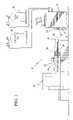
- FIG. 1is an overall system schematic of the cryosurgical probe system of the present invention, showing an environment with a patient positioned on a CT table prior to connection of the fluid lines and prior to being introduced into the CT device.
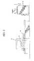
- FIG. 2is an overall system schematic showing a patient introduced into the CT device but prior to cryosurgical treatment.
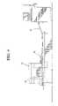
- FIG. 3shows the patient positioned away from the CT device and the cryosurgical probes attached to a manifold in preparation for cryosurgery.
- FIG. 4shows the patient introduced to the CT device and cryosurgery being performed under CT scanning guidance.
- FIG. 5is a perspective illustration of the cryosurgical probe inserted within the connector assembly.
- FIG. 6is a perspective illustration of the cryosurgical probe detached from the connector assembly.
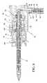
- FIG. 7is a cross-sectional view of the cryosurgical probe.
- FIG. 8is a cross-sectional view of the cryosurgical probe inserted within the connector assembly.
- FIG. 9shows an alternative embodiment of the cryosurgical probe in which a rigid curved portion is utilized and a connector assembly positioned proximal to the rigid curved portion.
- FIG. 10is a cross-sectional view of an embodiment of the cryosurgical probe system in which threads are utilized to secure the connector assembly relative to the cryosurgical probe.
- FIG. 10Ais an enlarged view of a portion of FIG. 10 .
- FIG. 11is a cross-sectional view of an embodiment of the cryosurgical probe system in which two Joule-Thomson nozzles are utilized, this embodiment being further differentiated by the use of a pushbutton/pin assembly to secure the connector assembly relative to the cryosurgical probe.
- FIG. 12is view taken along line 12 — 12 of FIG. 11 .
- FIG. 13is cross-sectional view of a portion of another embodiment in which a lever lock assembly is used to secure the connector assembly relative to the cryosurgical probe.
- FIG. 14is cross-sectional view of a portion of another embodiment in which a ball lock assembly is used to secure the connector assembly relative to the cryosurgical probe.
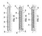
- FIG. 15is a cross-sectional view of a portion of a tube-in-tube sintered cryostat that may be used in lieu of the finned cryostat illustrated in the previous embodiments.
- FIG. 16is a cross-sectional view of a portion of a threaded cryostat.
- FIG. 17is a cross-sectional view of a portion of a coiled/sintered cryostat.
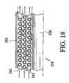
- FIG. 18is a cross-sectional view of a portion of a stacked coil cryostat.
- FIG. 1illustrates a preferred embodiment of the cryosurgical probe system of the present invention, designated generally as 10 .
- the cryosurgical probe system 10includes a fluid supply line 12 that is connected at an inlet section 14 to a source 16 of cryogenic fluid.
- the fluid source 16may be, for example, a cryosurgical system such as that manufactured by present assignee, Endocare, Inc., Irvine, Calif.
- a cryosurgical systemtypically utilizes argon gas from an argon gas source 18 to provide Joule-Thomson cooling of the cryosurgical probes.
- nitrogencan be used.
- a fluid supply systemcan be utilized that does not require an external fluid supply source.
- Heating of the cryosurgical probesis typically provided by a helium gas source 20 for providing a helium gas flow through the Joule-Thomson nozzle of the cryosurgical probe. This provides a heating effect. Such heating of the cryosurgical probes is provided to unstick the probes from the treated tissue for cryoprobe removal. Alternatively, other methods for warming may be used such as electrical heating via heated coils, microwave or RF heating.
- the fluid supply line 12preferably includes a manifold-system hose 22 for providing a connection from the source 16 to a manifold 24 .
- the manifold 24may be connected to a rail or otherwise to a CT table 26 .
- Manifold-fluid connector assembly hoses 28 of the fluid supply line 12provide fluid connections between fluid connector assemblies 30 and the manifold 24 .
- the fluid connector assemblies 30provide attachment to the detachable cryosurgical probes 32 .
- FIG. 1illustrates a patient 34 positioned on a CT table 26 adjacent to a CT device 36 .
- the cryosurgical probes 32have been inserted in treatment zones for cryosurgical treatment.
- the hoses 28are not yet connected to the manifold 24 . It is assumed that prior to probe insertion shown in FIG. 1 that the tumor location has been confirmed under imaging guidance (e.g. CT, ultrasound, etc.).
- the patient 34is introduced into the imaging section of the CT device 36 and scans are taken with the cryosurgical probes 32 inserted. These initial scans are made to assure that the tips of the cryosurgical probes 32 are properly positioned per a treatment plan.
- the patient 34is shown positioned away from the imaging section of the CT device 36 and the cryosurgical probes 32 are attached to the manifold 24 in preparation for cryosurgery.
- the patientis then again introduced to the device 36 and cryosurgery is performed under CT scanning. This allows for the monitoring of the iceballs formed during this procedure. There are typically two freeze-thaw cycles included in a cryosurgical treatment.
- a cryosurgical probe 32is shown inserted within its connector assembly 30 .
- a manifold-fluid connector assembly hose 28is shown with appropriate connector 38 for connection to the manifold 24 .
- the cryosurgical probe 32preferably includes a slideable wedge element 33 that can be used as a marker for assuring that the correct depth of the cryosurgical probe 32 is maintained. Furthermore, the bottom of the wedge element 33 contacts the body of the patient 34 to decrease the probability of accidental translation of the cryosurgical probe 32 .
- Spaced markings 35may be provided on the outer surface of the cryosurgical probe 32 . These markings 35 may be, for example, at 1 cm intervals.
- the cryosurgical probe 32is shown detached from its connector assembly 30 .
- the detachable cryosurgical probe 32includes a radially extending hub 38 that provides attachment to the connector assembly 30 .
- the cryosurgical probe 32includes a fluid delivery assembly, designated generally as 40 .
- the fluid delivery assembly 40includes a high pressure stem 42 , an extension tube 44 and an orifice tube 46 .
- the high pressure stem 42has a proximal end section that receives high pressure fluid from the fluid connector assembly 30 .
- the extension tube 44is welded, at a first end 48 , to the high pressure stem.
- the extension tube 44is in fluid communication with the high pressure stem 42 .
- the orifice tube 46is secured to a second end of the extension tube 44 .
- the orifice tube 46is in fluid communication with the extension tube 44 .
- the orifice tube 46comprises a Joule-Thomson (J-T) port at a distal end thereof.
- J-TJoule-Thomson
- the cryosurgical probe 32includes a return manifold assembly, designated generally as 50 .
- the return manifold assembly 50includes a low pressure stem 52 and a vacuum tube 54 .
- the low pressure stem 52is positioned about an outer surface of the high pressure stem 40 and is securely connected to the high pressure stem 40 . It may be secured via threads and adhesive or by welding.
- the vacuum tube 54is secured at an end 56 to the low pressure stem 52 .
- the vacuum tube 54has a desired insulative air gap 58 formed therein. The air gap 58 provides selected non-cooling areas of the cryosurgical probe 32 .
- the outer sheath 68is securely positioned over the return manifold assembly 50 .
- the outer sheath 68is a cylindrical tube preferably formed of stainless steel which provides the desired heat transfer characteristics.
- the outer sheath 68is welded to the low pressure stem 52 at location 70 . It is pointed at its closed distal end to provide insertion to the treatment area tissue.
- the outer sheath 68includes a cylindrical collector 72 having external threads 74 that cooperate with the cylindrical tube 68 to guide the return fluid from the J-T port 46 to the vacuum tube 54 , as will be explained below in detail.
- the hub 38is securely positioned over the outer sheath 68 and the return manifold assembly 50 .
- the hub 38is securely connected at weld location 76 to the outer sheath 68 and at weld location 78 to the low pressure stem 52 .
- the hub 38includes a cylindrical portion 80 and a tapered extension 82 extending therefrom.
- the tapered extension 82has a radial extending portion.
- the cylindrical portion 80is securely attached to the outer sheath 68 and the tapered extension is securely attached to the low pressure stem 52 .
- the connector assembly 30includes a substantially cylindrical connector housing 84 having a radially extending boss 86 securely attached to the outlet section 88 of the manifold-fluid connector assembly hose 28 of the fluid supply line 12 .
- the connector housing 84has a fluid inlet conduit 90 for receiving high pressure fluid from the fluid supply line 12 and a fluid outlet conduit 92 for transferring return fluid from the cryosurgical probe 32 to the fluid supply line 12 .
- the connector housing 84has a central axis parallel to the cryosurgical probe 32 .
- a cryostat 94is positioned in the manifold-fluid connector assembly hose 28 .
- the cryostat 94preferably has fins 95 .
- the fluid connector assemblyincludes a lock housing 96 , which is securely positioned within an axial opening of the connector housing 84 .
- the lock housing 96has a cylindrical portion 98 and a locking portion 100 .
- a spacing element 102axially positions the lock housing 100 relative to the connector housing 84 and radially positions the detachable cryosurgical probe 32 relative to the lock housing 96 .
- a high pressure seal 104is positioned relative to the cryosurgical probe 32 , the connector housing 84 and the spacing element 102 to contain the high pressure fluid within the connector housing 84 and enable the high pressure fluid to be delivered to the cryosurgical probe 32 .
- a low pressure seal 106is positioned relative to the cryosurgical probe 32 , the spacing element 102 , and the lock housing 100 to prevent return fluid leakage.
- a locking spring 108is positioned in the locking portion 100 of the lock housing 96 to provide detachable engagement of a cryosurgical probe positioned therein.
- thermocouple 107Positioned within the connector assembly 30 is a thermocouple 107 .
- the thermocouple 107is contained within a thermocouple housing tube 109 for providing temperature data.
- the thermocouple housing tube 109supports the cryostat 94 .
- cryogenic fluid originating from the argon tank 18flows through the manifold-fluid connector assembly hose 28 within the cryostat 94 and through the conduit 90 in the connector housing 84 .
- the flowis re-directed approximately 90 degrees, flows through the central passageway in the high pressure stem 42 , through the extension tube 44 , through the orifice tube 46 , and out of the J-T port.
- the return fluidAfter being expelled from the J-T port the return fluid is directed between the threads 74 of the cylindrical collector 72 and the outer sheath 68 . (The cylindrical collector 72 is not threaded into the outer sheath 68 and therefore the threads 74 provide a path for fluid flow.) The return flow then travels in the space between the inner surface of the vacuum tube 54 and the outer surface of the extension tube 44 . It then flows through openings 110 in the low-pressure stem 52 through the spacing element 102 and through the fluid outlet conduit 92 in the connector housing 84 . The return fluid is then expelled through the manifold-fluid connector assembly hose 28 .
- cryosurgical probe 32is shown with a pointed tip 112 to provide insertion into the patient's tissue for the desired application.
- the tipmay be blunt, depending on the application.
- direct insertionis desirable.
- insertion via a cannula/introduceris preferred.
- cryosurgical probe 32may be used with a variety of guidance tools, such as MRI and ultrasound.
- ultrasoundis used for initial guidance, followed up with CT for final confirmation.
- cryosurgical probehaving a rigid outer sheath
- the cryosurgical probemay be made to be malleable by including at least one malleable segment thereon.
- Malleable segmentsare formed of material that permit reshaping and bending to reposition the ablating surface for greater ablation precision.
- An example of a cryosurgical probe having malleable characteristicsis disclosed and claimed in our co-pending patent application Ser. No. 09/957,337, Pub. No. US 2003/0055415 A1, filed on Sep. 20, 2001 entitled Malleable Cryosurgical Probe, incorporated in its entirety herein by reference.
- One method for providing malleable characteristicsincludes providing a malleable shaft with a bellows portion.
- cryosurgical probehas been shown as having approximately a 90 degree extension from the point where the manifold-fluid connector assembly hoses 28 connect it is understood that this angle can vary depending on the desired application.
- the desired connection anglemay be, for example, in a broad range of from 0 degrees to 180 degrees (i.e. there may not be a bend).
- a preferred rangeis about 80 degrees to about 140 degrees.
- the outer sheathmay have an echogenic coating with, for example, a porous microstructure having the ability to trap microscopic air bubbles. This creates thousands of highly efficient ultrasound reflectors on the surface of the sheath.
- a fluid supply line 116is connectable at an inlet section to a source of cryogenic fluid (not shown).
- a fluid connector assembly 118is securely connected to an outlet section of the fluid supply line 116 for receiving fluid from the outlet section of the fluid supply line 116 .
- a detachable cryosurgical probe 120is detachably connectable to the fluid connector assembly 118 .
- the cryosurgical probe 120receives fluid from the fluid connector assembly 118 .
- the cryosurgical probe 120includes an angled extension assembly 122 .
- Angled extension assembly 122includes an angled portion 124 and extension portion 126 .
- the angled extension assembly 122in this embodiment, provides the ability to connect the fluid supply line 116 to the cryosurgical probe 120 without effecting the probe position within the patient (which has already been confirmed under image guidance).
- FIG. 10another embodiment of the cryosurgical probe system is illustrated, designated generally as 130 .
- a cryosurgical probe 132is shown inserted into a fluid connector assembly 134 .
- the connector assembly 134includes a substantially cylindrical lock housing 136 having an axially extending boss 140 securely attached to the outlet section 144 of a fluid supply line.
- the lock housing 136has a fluid inlet conduit 142 for receiving high pressure fluid from the fluid supply line and a fluid outlet conduit 146 for transferring return fluid from the cryosurgical probe 132 to the fluid supply line.
- a locking mechanismsuch as internal threads 148 provides secure attachment to the cryosurgical probe 132 .
- the fluid supply lineincludes a cryostat assembly 150 positioned adjacent to the outlet section 144 .
- the cryostat assembly 150may comprise one or a plurality of cryostats.
- the cryosurgical probe 132includes a fluid delivery/return manifold assembly, designated generally as 152 .
- the fluid delivery/return manifold assembly 152includes a fluid delivery section 154 and a return manifold section 156 .
- the return manifold section 156is positioned over a portion of the fluid delivery section 154 .
- the return manifold section 156includes an insulative vacuum sleeve 158 .
- the vacuum sleeve 158essentially comprises an outer tube 159 surrounding an inner tube 161 with a vacuum gap 169 therebetween.
- An outer sheath 160 of the cryosurgical probe 132is securely positioned over the vacuum sleeve 158 and extends from the fluid delivery/return manifold assembly 152 .
- a lock anchor 162 of the cryosurgical probe 132is securely positioned over the outer sheath 160 .
- the lock anchor 162provides for detachable connection to the fluid connector assembly 134 .
- This connectionmay be provided for, by example, threads 164 .
- a threaded extension 163extends axially from a main portion 165 of the lock anchor 162 .
- the threaded extension 163has the external threads 164 and also internal threads 167 .
- the internal threads 167provide connection to the fluid delivery/return manifold assembly 152 .
- the main portion 165is securely attached to the outer sheath 160 .
- fluidis delivered through the fluid inlet conduit 142 , through the fluid delivery section 154 of the fluid delivery/return manifold assembly 152 , through the Joule-Thomson (J-T) port 153 at a distal end of the fluid delivery section 154 and is returned through the return manifold section 156 and delivered out of the cryosurgical probe 132 and through the fluid connector assembly 134 .
- the insulative vacuum sleeve 158is provided between the outer sheath 160 and the return manifold section 156 at a control region of the outer sheath proximal to a distally located treatment region of the outer sheath.
- the fluid delivery/return manifold assembly 152includes a high pressure stem 166 for receiving high pressure fluid from the fluid connector assembly 134 .
- the high pressure stem 166is an elongated element with a circular cross-section and having a proximal circumferential groove 168 and a distal circumferential groove 170 .
- a low pressure seal 172is positioned within the proximal circumferential groove 168 to provide sealing engagement with a low pressure portion of the connector assembly 134 .
- a high pressure seal 174is positioned within the distal circumferential groove to provide sealing engagement with a high pressure portion of the connector assembly 134 . (The low pressure seal 172 actually sees both high pressure and low pressure.)
- the fluid delivery/return manifold assembly 152also includes an extension tube 176 and orifice tube 178 .
- a first end of the extension tube 176is secured within the high pressure stem 166 .
- the second, opposite endis secured to the orifice tube 178 .
- the distal end of the orifice tube 178functions as the J-T port 153 .
- a portion of the return fluid flow passagewayis provided in a space formed between an inner surface of the vacuum sleeve 158 and an outer surface of the extension tube 176 .
- the sheath 160further contains a coil collector, i.e. copper wire 182 , which cooperates with the sheath 160 to guide the return fluid from the J-T port 153 to the vacuum sleeve 158 .
- the coil collectorcan be hand-formed or machine-formed.
- cryosurgical probedesignated generally as 188
- the cryosurgical probeincludes two extension tubes 190 , 192 providing two J-T ports 192 for increased power.
- the J-T ports 192may be made to be axially spaced. This provides the ability to create an elongated iceball although the desired elongation is typically provided by the desired positioning of the insulative vacuum sleeve 194 .
- this embodimentillustrates that there are a variety of different locking mechanisms that may be used to contain the cryosurgical probe 188 within the connector assembly 196 . Some of these locking mechanisms may be quick disconnect mechanisms.
- a pushbutton/pin assembly 198is utilized. This assembly is in a normally locked position and unlocked upon application of the pushbutton 199 .
- a lever lock assemblyis illustrated, designated generally as 200 , as a means for securing the cryosurgical probe 202 to a connector assembly 204 .
- the lever lock assembly 200includes a spring 206 for biasing a locking piece 208 that cooperates with a recessed area of a lock housing 210 of the connector assembly 204 .
- a ball lock assemblydesignated generally as 212 , is illustrated, in which a sleeve 214 is biased by a spring 216 .
- Thisprovides the desired securing of a locking element 218 within a recessed area of a cryosurgical probe, designated generally as 220 . Locking of the cryosurgical probe 220 relative to the connector assembly 222 is thus provided.
- the above-identified examples of attachmentare shown by way of illustration. There are many other securing means that could be implemented.
- Tube-in-tube sintered cryostat 224includes an inner tube 226 positioned within an outer tube 228 .
- Sintered material 230 , 232is in both tubes 226 , 228 .
- Such sintered materialmay be, for example, stranded copper alloy wire.
- the outer tube 228serves to provide access for inlet gas 229 while the inner tube 230 provides access for outlet gas 231 .
- Use of cryostat 224may minimize labor and part costs.
- a threaded cryostat 234is illustrated.
- an inner tube 236is positioned within an outer tube 238 .
- a threaded element 240is positioned between the outer tube 238 and the inner tube 236 .
- the threaded element 240has exterior threads and interior threads that provide heat exchange for inlet gas 242 and outlet gas 244 .
- This approachmay also provide reduced labor and part costs. It is noted that this can be alternatively be implemented so that inlet gas may be introduced between the inner tube 236 and the interior threads. Outlet gas flows between the outer tube 238 and the exterior threads.
- the threaded element 240is preferably formed of highly thermally conductive and high strength material such as copper alloy material.
- interior threads of the threaded element 240may be eliminated and substituted with an inner tube 236 that is formed of sintered metal or a metal coil.
- a coiled/sintered cryostatis illustrated, designated generally as 246 .
- This heat exchangerincludes an inner tube 248 positioned within an outer tube 250 .
- Sintered material 252is provided in the space formed between the concentric tubes 248 , 250 .
- a coil 254is located in that space within the sintered material 252 . This approach may also provide beneficial labor and part costs. Additionally, it maximizes heat exchange efficiency.
- a stacked coil cryostatis illustrated, designated generally as 256 .
- This heat exchangerincludes an inner tube 258 positioned within an outer tube 260 .
- Stacked coils 262are provided in the space formed between the concentric tubes 258 , 260 .
- the coils 262may be formed of, for example, copper alloy material.
- This embodimenthas the advantage of minimal material costs. It is noted that in all of the embodiments described relative to FIGS. 15–18 the fluid directions can be reversed depending on the particular design constraints.
- a manifold-system hose 22 and manifold 24may not be included.
- a manifold-fluid connector assembly hose 28 with connector 38would be replaced with a fluid supply line that connects the connector assembly 30 directly at an inlet section 14 to a source 16 of cryogenic fluid.
- cryostat 94has been shown positioned within the manifold-fluid connector assembly hose 28 it may be positioned in other locations, notably, for example, in the manifold 24 or within the source 16 .
- cryosurgical probe systemis particularly advantageous for radiological applications it is also advantageous for many other types of ablation applications, such as prostate cryosurgery and other operating room based procedures.
Landscapes
- Engineering & Computer Science (AREA)
- Health & Medical Sciences (AREA)
- Surgery (AREA)
- Life Sciences & Earth Sciences (AREA)
- Mechanical Engineering (AREA)
- Thermal Sciences (AREA)
- General Engineering & Computer Science (AREA)
- Nuclear Medicine, Radiotherapy & Molecular Imaging (AREA)
- Physics & Mathematics (AREA)
- Biomedical Technology (AREA)
- Otolaryngology (AREA)
- Heart & Thoracic Surgery (AREA)
- Medical Informatics (AREA)
- Molecular Biology (AREA)
- Animal Behavior & Ethology (AREA)
- General Health & Medical Sciences (AREA)
- Public Health (AREA)
- Veterinary Medicine (AREA)
- Surgical Instruments (AREA)
- Quick-Acting Or Multi-Walled Pipe Joints (AREA)
Abstract
Description
Claims (50)
Priority Applications (11)
| Application Number | Priority Date | Filing Date | Title |
|---|---|---|---|
| US10/828,031US7160291B2 (en) | 2003-06-25 | 2004-04-20 | Detachable cryosurgical probe |
| CA2530710ACA2530710C (en) | 2003-06-25 | 2004-06-24 | Detachable cryosurgical probe |
| PCT/US2004/020324WO2005000106A2 (en) | 2003-06-25 | 2004-06-24 | Detachable cryosurgical probe |
| EP04777038.3AEP1648282B1 (en) | 2003-06-25 | 2004-06-24 | Detachable cryosurgical probe |
| ES12003928.4TES2617511T3 (en) | 2003-06-25 | 2004-06-24 | Cryostat for a cryosurgical system |
| CN2004800177932ACN1812748B (en) | 2003-06-25 | 2004-06-24 | Detachable cryosurgical probe |
| EP12003928.4AEP2497436B1 (en) | 2003-06-25 | 2004-06-24 | Cryostat for a cryosurgical system |
| US10/954,433US7361187B2 (en) | 2003-06-25 | 2004-09-30 | Threaded cryostat for cryosurgical probe system |
| PCT/US2005/012372WO2005104974A2 (en) | 2004-04-20 | 2005-04-13 | Threaded cryostat for cryosurgical probe system |
| IL172782AIL172782A (en) | 2003-06-25 | 2005-12-22 | Detachable cryosurgical probe |
| US11/529,615US7485117B2 (en) | 2003-06-25 | 2006-09-28 | Detachable cryosurgical probe |
Applications Claiming Priority (2)
| Application Number | Priority Date | Filing Date | Title |
|---|---|---|---|
| US10/603,883US7207985B2 (en) | 2003-06-25 | 2003-06-25 | Detachable cryosurgical probe |
| US10/828,031US7160291B2 (en) | 2003-06-25 | 2004-04-20 | Detachable cryosurgical probe |
Related Parent Applications (1)
| Application Number | Title | Priority Date | Filing Date |
|---|---|---|---|
| US10/603,883Continuation-In-PartUS7207985B2 (en) | 2003-06-25 | 2003-06-25 | Detachable cryosurgical probe |
Related Child Applications (2)
| Application Number | Title | Priority Date | Filing Date |
|---|---|---|---|
| US10/954,433Continuation-In-PartUS7361187B2 (en) | 2003-06-25 | 2004-09-30 | Threaded cryostat for cryosurgical probe system |
| US11/529,615DivisionUS7485117B2 (en) | 2003-06-25 | 2006-09-28 | Detachable cryosurgical probe |
Publications (2)
| Publication Number | Publication Date |
|---|---|
| US20050010200A1 US20050010200A1 (en) | 2005-01-13 |
| US7160291B2true US7160291B2 (en) | 2007-01-09 |
Family
ID=33555807
Family Applications (3)
| Application Number | Title | Priority Date | Filing Date |
|---|---|---|---|
| US10/828,031Expired - LifetimeUS7160291B2 (en) | 2003-06-25 | 2004-04-20 | Detachable cryosurgical probe |
| US10/954,433Expired - LifetimeUS7361187B2 (en) | 2003-06-25 | 2004-09-30 | Threaded cryostat for cryosurgical probe system |
| US11/529,615Expired - LifetimeUS7485117B2 (en) | 2003-06-25 | 2006-09-28 | Detachable cryosurgical probe |
Family Applications After (2)
| Application Number | Title | Priority Date | Filing Date |
|---|---|---|---|
| US10/954,433Expired - LifetimeUS7361187B2 (en) | 2003-06-25 | 2004-09-30 | Threaded cryostat for cryosurgical probe system |
| US11/529,615Expired - LifetimeUS7485117B2 (en) | 2003-06-25 | 2006-09-28 | Detachable cryosurgical probe |
Country Status (6)
| Country | Link |
|---|---|
| US (3) | US7160291B2 (en) |
| EP (2) | EP1648282B1 (en) |
| CN (1) | CN1812748B (en) |
| CA (1) | CA2530710C (en) |
| ES (1) | ES2617511T3 (en) |
| WO (1) | WO2005000106A2 (en) |
Cited By (29)
| Publication number | Priority date | Publication date | Assignee | Title |
|---|---|---|---|---|
| US20070167939A1 (en)* | 2003-06-25 | 2007-07-19 | Endocare, Inc. | Quick disconnect assembly having a finger lock assembly |
| US20070191824A1 (en)* | 2003-06-25 | 2007-08-16 | Endocare, Inc. | Detachable cryosurgical probe |
| US20080140061A1 (en)* | 2006-09-08 | 2008-06-12 | Arbel Medical Ltd. | Method And Device For Combined Treatment |
| US20080208181A1 (en)* | 2007-01-19 | 2008-08-28 | Arbel Medical Ltd. | Thermally Insulated Needles For Dermatological Applications |
| US20090129946A1 (en)* | 2007-11-21 | 2009-05-21 | Arbel Medical, Ltd. | Pumping unit for delivery of liquid medium from a vessel |
| US7608071B2 (en) | 2003-06-25 | 2009-10-27 | Endocare, Inc. | Cryosurgical probe with adjustable sliding apparatus |
| US20100057067A1 (en)* | 2008-09-03 | 2010-03-04 | Baust John M | Modular pulsed pressure device for the transport of liquid cryogen to a cryoprobe |
| US20100057064A1 (en)* | 2008-09-03 | 2010-03-04 | Baust John M | Medical Device for the Transport of Subcooled Cryogenic Fluid through a Linear Heat Exchanger |
| US20100057063A1 (en)* | 2008-07-03 | 2010-03-04 | Steve Arless | Tip design for cryogenic probe with inner coil injection tube |
| US20100162730A1 (en)* | 2007-06-14 | 2010-07-01 | Arbel Medical Ltd. | Siphon for delivery of liquid cryogen from dewar flask |
| US20100234670A1 (en)* | 2009-03-12 | 2010-09-16 | Eyal Shai | Combined cryotherapy and brachytherapy device and method |
| US20100281917A1 (en)* | 2008-11-05 | 2010-11-11 | Alexander Levin | Apparatus and Method for Condensing Contaminants for a Cryogenic System |
| US20100305439A1 (en)* | 2009-05-27 | 2010-12-02 | Eyal Shai | Device and Method for Three-Dimensional Guidance and Three-Dimensional Monitoring of Cryoablation |
| US20100324546A1 (en)* | 2007-07-09 | 2010-12-23 | Alexander Levin | Cryosheath |
| US20110015624A1 (en)* | 2008-01-15 | 2011-01-20 | Icecure Medical Ltd. | Cryosurgical instrument insulating system |
| US7938822B1 (en) | 2010-05-12 | 2011-05-10 | Icecure Medical Ltd. | Heating and cooling of cryosurgical instrument using a single cryogen |
| US20110152849A1 (en)* | 2008-09-03 | 2011-06-23 | Baust John M | Cryogenic System and Method of Use |
| US7967814B2 (en) | 2009-02-05 | 2011-06-28 | Icecure Medical Ltd. | Cryoprobe with vibrating mechanism |
| US7967815B1 (en) | 2010-03-25 | 2011-06-28 | Icecure Medical Ltd. | Cryosurgical instrument with enhanced heat transfer |
| US8080005B1 (en) | 2010-06-10 | 2011-12-20 | Icecure Medical Ltd. | Closed loop cryosurgical pressure and flow regulated system |
| US8083733B2 (en) | 2008-04-16 | 2011-12-27 | Icecure Medical Ltd. | Cryosurgical instrument with enhanced heat exchange |
| US9089316B2 (en) | 2009-11-02 | 2015-07-28 | Endocare, Inc. | Cryogenic medical system |
| US20150313473A1 (en)* | 2012-12-18 | 2015-11-05 | Koninklijke Philips N.V. | Reusable mr safe temperature probe for surface and body temperature measurement |
| US9980764B2 (en) | 2010-08-04 | 2018-05-29 | Erbe Elektromedizin Gmbh | Handle for a surgical instrument, in particular a cryosurgical instrument |
| WO2021086847A1 (en) | 2019-10-29 | 2021-05-06 | Pacira Cryotech, Inc. | Cryogenic device with quick-connect needle probes |
| US11633224B2 (en) | 2020-02-10 | 2023-04-25 | Icecure Medical Ltd. | Cryogen pump |
| US11648047B2 (en) | 2017-10-06 | 2023-05-16 | Vive Scientific, Llc | System and method to treat obstructive sleep apnea |
| US12215811B2 (en) | 2022-07-18 | 2025-02-04 | Icecure Medical Ltd. | Cryogenic system connector |
| US12426934B2 (en) | 2022-02-28 | 2025-09-30 | Icecure Medical Ltd. | Cryogen flow control |
Families Citing this family (71)
| Publication number | Priority date | Publication date | Assignee | Title |
|---|---|---|---|---|
| US7363071B2 (en) | 1999-05-26 | 2008-04-22 | Endocare, Inc. | Computer guided ablation of tissue using integrated ablative/temperature sensing devices |
| US7189228B2 (en) | 2003-06-25 | 2007-03-13 | Endocare, Inc. | Detachable cryosurgical probe with breakaway handle |
| US7160291B2 (en)* | 2003-06-25 | 2007-01-09 | Endocare, Inc. | Detachable cryosurgical probe |
| US8029502B2 (en)* | 2005-05-19 | 2011-10-04 | Endocare, Inc. | Cryosurgical probe assembly with multiple deployable cryoprobes |
| US7850683B2 (en) | 2005-05-20 | 2010-12-14 | Myoscience, Inc. | Subdermal cryogenic remodeling of muscles, nerves, connective tissue, and/or adipose tissue (fat) |
| US7713266B2 (en) | 2005-05-20 | 2010-05-11 | Myoscience, Inc. | Subdermal cryogenic remodeling of muscles, nerves, connective tissue, and/or adipose tissue (fat) |
| US20070149959A1 (en)* | 2005-12-23 | 2007-06-28 | Sanarus Medical, Inc. | Cryoprobe for low pressure systems |
| US20080016901A1 (en)* | 2006-07-24 | 2008-01-24 | Leary Wilson M | Heat exchanger |
| US7763018B2 (en)* | 2006-07-28 | 2010-07-27 | Covidien Ag | Cool-tip thermocouple including two-piece hub |
| DE102007020582A1 (en)* | 2006-12-19 | 2008-06-26 | Erbe Elektromedizin Gmbh | A cryosurgical instrument and method for separating a tissue sample from surrounding tissue of a biological tissue to be treated |
| US9254162B2 (en) | 2006-12-21 | 2016-02-09 | Myoscience, Inc. | Dermal and transdermal cryogenic microprobe systems |
| WO2008077317A1 (en)* | 2006-12-26 | 2008-07-03 | Accutarget Medipharma (Shanghai) Corp. Ltd. | Radio frequency ablation system with joule-thomson cooler |
| US8187260B1 (en) | 2006-12-29 | 2012-05-29 | Endocare, Inc. | Variable cryosurgical probe planning system |
| US8409185B2 (en) | 2007-02-16 | 2013-04-02 | Myoscience, Inc. | Replaceable and/or easily removable needle systems for dermal and transdermal cryogenic remodeling |
| FR2916625B1 (en)* | 2007-05-31 | 2010-08-20 | Phakos | CRYOGENIC DEVICE FOR SURGICAL USE |
| US20120089136A1 (en)* | 2007-08-13 | 2012-04-12 | Alexander Levin | Cryosurgical instrument with quick coupling mechanism |
| WO2009065061A1 (en) | 2007-11-14 | 2009-05-22 | Myoscience, Inc. | Pain management using cryogenic remodeling |
| DE102008010477A1 (en)* | 2008-02-21 | 2009-09-03 | Erbe Elektromedizin Gmbh | Cryosurgical instrument |
| EP2837348B1 (en) | 2008-06-11 | 2020-04-08 | CryoConcepts LP | Cryo-surgical methods of use |
| US20110178514A1 (en)* | 2008-06-18 | 2011-07-21 | Alexander Levin | Cryosurgical Instrument Insulating System |
| JP5642087B2 (en) | 2008-12-22 | 2014-12-17 | ミオサイエンス インコーポレーティッド | Integrated cryosurgery system with refrigerant and power supply |
| US20110230873A1 (en)* | 2010-03-22 | 2011-09-22 | Mark Chak | Method mini refrigerator and apparatus for treating diseases |
| WO2012036914A1 (en)* | 2010-09-15 | 2012-03-22 | Icecure Medical Ltd. | Cryosurgical instrument for treating large volume of tissue |
| US20120109117A1 (en)* | 2010-10-28 | 2012-05-03 | Adam Harp | Cryogenic probe with swivel |
| WO2012121786A1 (en)* | 2011-03-09 | 2012-09-13 | Icecure Medical Ltd. | Cryosurgical instrument with redirected flow |
| US9039689B2 (en)* | 2011-05-11 | 2015-05-26 | Icecure Medical Ltd. | Phase separation of cryogen in cryosurgical instrument |
| CN103442657B (en) | 2011-05-11 | 2016-05-25 | 艾斯酷瑞医药有限公司 | For the coil exchanger of Cryobiopsy probe |
| CN104159534B (en) | 2012-01-13 | 2017-02-22 | 肌肉科技股份有限公司 | Skin protection for subdermal cryogenic remodeling for cosmetic and other treatments |
| WO2013106860A1 (en) | 2012-01-13 | 2013-07-18 | Myoscience, Inc. | Cryogenic probe filtration system |
| EP2802279B1 (en) | 2012-01-13 | 2017-08-16 | Myoscience, Inc. | Cryogenic needle with freeze zone regulation |
| US9017318B2 (en) | 2012-01-20 | 2015-04-28 | Myoscience, Inc. | Cryogenic probe system and method |
| US9243726B2 (en) | 2012-10-03 | 2016-01-26 | Aarne H. Reid | Vacuum insulated structure with end fitting and method of making same |
| ES2717013T3 (en)* | 2012-10-30 | 2019-06-18 | Nitro Medical Ltd | Apparatus and probe for a cryogenic system |
| CN103006315B (en)* | 2013-01-09 | 2015-05-27 | 中国科学技术大学 | Freezing-heating tool |
| CN103006316B (en)* | 2013-01-09 | 2015-11-25 | 中国科学技术大学 | A kind of cold and hot cutter |
| US9295512B2 (en) | 2013-03-15 | 2016-03-29 | Myoscience, Inc. | Methods and devices for pain management |
| WO2014146127A1 (en) | 2013-03-15 | 2014-09-18 | Myoscience, Inc. | Methods and systems for treatment of spasticity |
| US9610112B2 (en) | 2013-03-15 | 2017-04-04 | Myoscience, Inc. | Cryogenic enhancement of joint function, alleviation of joint stiffness and/or alleviation of pain associated with osteoarthritis |
| WO2014146126A1 (en) | 2013-03-15 | 2014-09-18 | Myoscience, Inc. | Cryogenic blunt dissection methods and devices |
| EP3025081A4 (en)* | 2013-07-26 | 2017-04-19 | Bruker BioSpin Corporation | Flexible interface cryocast with remote cooling |
| US10130409B2 (en) | 2013-11-05 | 2018-11-20 | Myoscience, Inc. | Secure cryosurgical treatment system |
| US9463918B2 (en) | 2014-02-20 | 2016-10-11 | Aarne H. Reid | Vacuum insulated articles and methods of making same |
| CN105286984B (en)* | 2014-07-18 | 2018-04-17 | 神讯电脑(昆山)有限公司 | The quick-disassembly structure of electronics operation device |
| CN105496547B (en)* | 2014-09-26 | 2018-08-10 | 神讯电脑(昆山)有限公司 | The fixed structure of electronics operation device |
| US10390871B2 (en)* | 2015-02-20 | 2019-08-27 | Galil Medical Inc. | Cryoneedle |
| CN104758049A (en)* | 2015-04-13 | 2015-07-08 | 北京阳光易帮医疗科技有限公司 | Ultra-low temperature freezing probe and use method thereof |
| US10497908B2 (en) | 2015-08-24 | 2019-12-03 | Concept Group, Llc | Sealed packages for electronic and energy storage devices |
| US10065256B2 (en) | 2015-10-30 | 2018-09-04 | Concept Group Llc | Brazing systems and methods |
| CN109154641B (en) | 2016-03-04 | 2021-09-17 | 概念集团有限责任公司 | Vacuum insulation article with reflective material enhancement |
| EP4349396A3 (en) | 2016-05-13 | 2024-05-01 | Pacira CryoTech, Inc. | Systems for locating and treating with cold therapy |
| FR3052245B1 (en)* | 2016-06-06 | 2019-06-14 | Societe Francaise De Detecteurs Infrarouges - Sofradir | CRYOGENIC DEVICE WITH COMPACT EXCHANGER |
| WO2018093773A1 (en) | 2016-11-15 | 2018-05-24 | Reid Aarne H | Multiply-insulated assemblies |
| CA3043915A1 (en) | 2016-11-15 | 2018-05-24 | Concept Group Llc | Enhanced vacuum-insulated articles with microporous insulation |
| CN106725826A (en)* | 2017-01-11 | 2017-05-31 | 上海导向医疗系统有限公司 | The flexible cryoprobe of enhancing cutter head security and fixed J T groove locations |
| US11413085B2 (en)* | 2017-04-27 | 2022-08-16 | Medtronic Holding Company Sàrl | Cryoprobe |
| US20180310977A1 (en)* | 2017-04-28 | 2018-11-01 | Kyphon SÀRL | Introducer and cryoprobe |
| US11320086B2 (en) | 2017-08-25 | 2022-05-03 | Concept Group Llc | Multiple geometry and multiple material insulated components |
| CN116919565A (en) | 2017-11-13 | 2023-10-24 | 生物相容英国有限公司 | Cryoablation system with magnetic resonance imaging detection |
| WO2019092613A1 (en) | 2017-11-13 | 2019-05-16 | Biocompatibles Uk Limited | Cryoprobe for magnetic resonance imaging |
| EP3709918B1 (en) | 2017-11-15 | 2025-06-18 | Pacira CryoTech, Inc. | Integrated cold therapy and electrical stimulation systems for locating and treating nerves |
| CN115486927B (en)* | 2017-11-27 | 2025-02-25 | 海杰亚(北京)医疗器械有限公司 | Cryoablation needle |
| EP4570191A3 (en)* | 2018-03-02 | 2025-08-20 | The General Hospital Corporation | Devices, systems, and methods for cryogenic biopsy sampling |
| CN108498163B (en)* | 2018-04-24 | 2020-07-28 | 海杰亚(北京)医疗器械有限公司 | Vacuum interlayer treatment process for split connection cryoablation needle |
| US11179185B2 (en)* | 2018-07-20 | 2021-11-23 | Atricure, Inc. | Cryogenic surgical systems |
| WO2020092981A1 (en)* | 2018-11-01 | 2020-05-07 | Biocompatibles Uk Limited | Cryoprobe with stiffening element |
| CN109730763B (en)* | 2019-02-28 | 2024-11-22 | 上海导向医疗系统有限公司 | Split flexible cryoablation needle device |
| AU2020245381A1 (en)* | 2019-03-25 | 2021-11-04 | Biocompatibles Uk Limited | Cryoprobe |
| CN110251224B (en)* | 2019-08-13 | 2020-02-07 | 上海导向医疗系统有限公司 | Adjustable cryoablation needle |
| CN114305649B (en)* | 2021-11-19 | 2022-08-02 | 海杰亚(北京)医疗器械有限公司 | Cold and hot melting needle system |
| CN115137468B (en)* | 2022-07-13 | 2022-11-25 | 海杰亚(北京)医疗器械有限公司 | Non-vacuum fluid transfer device and ablation needle system |
| US20240200846A1 (en)* | 2022-12-14 | 2024-06-20 | International Business Machines Corporation | Modular cooling farm for cryogenic application |
Citations (24)
| Publication number | Priority date | Publication date | Assignee | Title |
|---|---|---|---|---|
| US3524446A (en)* | 1968-05-31 | 1970-08-18 | Frigitronics Of Conn Inc | Disposable cryosurgical instrument |
| US4018227A (en)* | 1975-10-09 | 1977-04-19 | Cryomedics, Inc. | Cryosurgical instrument |
| US4206760A (en)* | 1978-06-30 | 1980-06-10 | Cryomedics, Inc. | Bearing coupling for enabling the tip of a cryosurgical instrument to be rotated independently of inlet and exhaust tubes |
| US5224943A (en)* | 1988-12-17 | 1993-07-06 | Spembly Medical Ltd. | Cryosurgical apparatus |
| US5254116A (en)* | 1991-09-06 | 1993-10-19 | Cryomedical Sciences, Inc. | Cryosurgical instrument with vent holes and method using same |
| US5281213A (en)* | 1992-04-16 | 1994-01-25 | Implemed, Inc. | Catheter for ice mapping and ablation |
| US5452582A (en)* | 1994-07-06 | 1995-09-26 | Apd Cryogenics, Inc. | Cryo-probe |
| US5520682A (en)* | 1991-09-06 | 1996-05-28 | Cryomedical Sciences, Inc. | Cryosurgical instrument with vent means and method using same |
| US5800487A (en) | 1996-07-23 | 1998-09-01 | Endocare, Inc. | Cryoprobe |
| US5910104A (en) | 1996-12-26 | 1999-06-08 | Cryogen, Inc. | Cryosurgical probe with disposable sheath |
| US5978697A (en) | 1998-01-05 | 1999-11-02 | Galil Medical Ltd. | System and method for MRI-guided cryosurgery |
| US5992158A (en)* | 1994-05-10 | 1999-11-30 | Spembly Medical Limited | Cryosurgical instrument |
| US6106517A (en)* | 1994-06-23 | 2000-08-22 | Situs Corporation | Surgical instrument with ultrasound pulse generator |
| US6306129B1 (en) | 1997-09-22 | 2001-10-23 | Femrx, Inc. | Cryosurgical system and method |
| US20020022832A1 (en) | 1998-06-19 | 2002-02-21 | Mikus Paul W. | Cryoprobe assembly with detachable sheath |
| US6374619B1 (en)* | 1999-11-18 | 2002-04-23 | Raytheon Company | Adiabatic micro-cryostat system and method of making same |
| US20020188287A1 (en)* | 2001-05-21 | 2002-12-12 | Roni Zvuloni | Apparatus and method for cryosurgery within a body cavity |
| US20030055415A1 (en) | 2001-09-20 | 2003-03-20 | Xiaoyu Yu | Malleable cryosurgical probe |
| US20030055416A1 (en) | 2001-09-20 | 2003-03-20 | Damasco Sanford D. | Cryosurgical probe with bellows shaft |
| US20030078570A1 (en)* | 2001-10-23 | 2003-04-24 | Wilfred Peter Heiner | Cryoablation catheter for long lesion ablations |
| US20030195605A1 (en)* | 2001-08-21 | 2003-10-16 | Kovalcheck Steven W. | Cryogenic catheter with deflectable tip |
| US20040049177A1 (en)* | 2000-10-24 | 2004-03-11 | Roni Zvuloni | Multiple cryoprobe apparatus and method |
| US6755823B2 (en)* | 2001-02-28 | 2004-06-29 | Cryocath Technologies Inc. | Medical device with enhanced cooling power |
| US6786902B1 (en)* | 1996-06-24 | 2004-09-07 | Allegheny-Singer Research Institute | Method and apparatus for cryosurgery |
Family Cites Families (17)
| Publication number | Priority date | Publication date | Assignee | Title |
|---|---|---|---|---|
| FR2034754A6 (en)* | 1968-03-06 | 1970-12-18 | Mille Gaston | |
| US3800552A (en) | 1972-03-29 | 1974-04-02 | Bendix Corp | Cryogenic surgical instrument |
| DE2831199C3 (en) | 1978-07-15 | 1981-01-08 | Erbe Elektromedizin Gmbh & Co Kg, 7400 Tuebingen | Cryosurgical device |
| US4381652A (en)* | 1982-01-15 | 1983-05-03 | Santa Barbara Research Center | Demand flow cryostat |
| US5108390A (en)* | 1988-11-14 | 1992-04-28 | Frigitronics, Inc. | Flexible cryoprobe |
| GB2226497B (en)* | 1988-12-01 | 1992-07-01 | Spembly Medical Ltd | Cryosurgical probe |
| US4946460A (en)* | 1989-04-26 | 1990-08-07 | Cryo Instruments, Inc. | Apparatus for cryosurgery |
| ZA917281B (en)* | 1990-09-26 | 1992-08-26 | Cryomedical Sciences Inc | Cryosurgical instrument and system and method of cryosurgery |
| GB2283678B (en)* | 1993-11-09 | 1998-06-03 | Spembly Medical Ltd | Cryosurgical catheter probe |
| US5885276A (en)* | 1997-12-02 | 1999-03-23 | Galil Medical Ltd. | Method and device for transmyocardial cryo revascularization |
| US6251105B1 (en)* | 1998-03-31 | 2001-06-26 | Endocare, Inc. | Cryoprobe system |
| US6270476B1 (en)* | 1999-04-23 | 2001-08-07 | Cryocath Technologies, Inc. | Catheter |
| US6551309B1 (en) | 2000-09-14 | 2003-04-22 | Cryoflex, Inc. | Dual action cryoprobe and methods of using the same |
| CN2458995Y (en)* | 2001-01-20 | 2001-11-14 | 中国科学院理化技术研究所 | Immersion cooling type cold knife device capable of promoting quick temperature rise and melting of frozen tumor tissue |
| DE20109980U1 (en)* | 2001-06-16 | 2002-10-17 | Tricumed Medizintechnik GmbH, 24143 Kiel | Plug-in coupling for a cryoprobe |
| US7101367B2 (en)* | 2002-09-30 | 2006-09-05 | Ethicon, Inc. | Deployable cryosurgical catheter |
| US7160291B2 (en)* | 2003-06-25 | 2007-01-09 | Endocare, Inc. | Detachable cryosurgical probe |
- 2004
- 2004-04-20USUS10/828,031patent/US7160291B2/ennot_activeExpired - Lifetime
- 2004-06-24WOPCT/US2004/020324patent/WO2005000106A2/enactiveApplication Filing
- 2004-06-24EPEP04777038.3Apatent/EP1648282B1/ennot_activeExpired - Lifetime
- 2004-06-24CACA2530710Apatent/CA2530710C/ennot_activeExpired - Fee Related
- 2004-06-24ESES12003928.4Tpatent/ES2617511T3/ennot_activeExpired - Lifetime
- 2004-06-24CNCN2004800177932Apatent/CN1812748B/ennot_activeExpired - Fee Related
- 2004-06-24EPEP12003928.4Apatent/EP2497436B1/ennot_activeExpired - Lifetime
- 2004-09-30USUS10/954,433patent/US7361187B2/ennot_activeExpired - Lifetime
- 2006
- 2006-09-28USUS11/529,615patent/US7485117B2/ennot_activeExpired - Lifetime
Patent Citations (24)
| Publication number | Priority date | Publication date | Assignee | Title |
|---|---|---|---|---|
| US3524446A (en)* | 1968-05-31 | 1970-08-18 | Frigitronics Of Conn Inc | Disposable cryosurgical instrument |
| US4018227A (en)* | 1975-10-09 | 1977-04-19 | Cryomedics, Inc. | Cryosurgical instrument |
| US4206760A (en)* | 1978-06-30 | 1980-06-10 | Cryomedics, Inc. | Bearing coupling for enabling the tip of a cryosurgical instrument to be rotated independently of inlet and exhaust tubes |
| US5224943A (en)* | 1988-12-17 | 1993-07-06 | Spembly Medical Ltd. | Cryosurgical apparatus |
| US5254116A (en)* | 1991-09-06 | 1993-10-19 | Cryomedical Sciences, Inc. | Cryosurgical instrument with vent holes and method using same |
| US5520682A (en)* | 1991-09-06 | 1996-05-28 | Cryomedical Sciences, Inc. | Cryosurgical instrument with vent means and method using same |
| US5281213A (en)* | 1992-04-16 | 1994-01-25 | Implemed, Inc. | Catheter for ice mapping and ablation |
| US5992158A (en)* | 1994-05-10 | 1999-11-30 | Spembly Medical Limited | Cryosurgical instrument |
| US6106517A (en)* | 1994-06-23 | 2000-08-22 | Situs Corporation | Surgical instrument with ultrasound pulse generator |
| US5452582A (en)* | 1994-07-06 | 1995-09-26 | Apd Cryogenics, Inc. | Cryo-probe |
| US6786902B1 (en)* | 1996-06-24 | 2004-09-07 | Allegheny-Singer Research Institute | Method and apparatus for cryosurgery |
| US5800487A (en) | 1996-07-23 | 1998-09-01 | Endocare, Inc. | Cryoprobe |
| US5910104A (en) | 1996-12-26 | 1999-06-08 | Cryogen, Inc. | Cryosurgical probe with disposable sheath |
| US6306129B1 (en) | 1997-09-22 | 2001-10-23 | Femrx, Inc. | Cryosurgical system and method |
| US5978697A (en) | 1998-01-05 | 1999-11-02 | Galil Medical Ltd. | System and method for MRI-guided cryosurgery |
| US20020022832A1 (en) | 1998-06-19 | 2002-02-21 | Mikus Paul W. | Cryoprobe assembly with detachable sheath |
| US6374619B1 (en)* | 1999-11-18 | 2002-04-23 | Raytheon Company | Adiabatic micro-cryostat system and method of making same |
| US20040049177A1 (en)* | 2000-10-24 | 2004-03-11 | Roni Zvuloni | Multiple cryoprobe apparatus and method |
| US6755823B2 (en)* | 2001-02-28 | 2004-06-29 | Cryocath Technologies Inc. | Medical device with enhanced cooling power |
| US20020188287A1 (en)* | 2001-05-21 | 2002-12-12 | Roni Zvuloni | Apparatus and method for cryosurgery within a body cavity |
| US20030195605A1 (en)* | 2001-08-21 | 2003-10-16 | Kovalcheck Steven W. | Cryogenic catheter with deflectable tip |
| US20030055416A1 (en) | 2001-09-20 | 2003-03-20 | Damasco Sanford D. | Cryosurgical probe with bellows shaft |
| US20030055415A1 (en) | 2001-09-20 | 2003-03-20 | Xiaoyu Yu | Malleable cryosurgical probe |
| US20030078570A1 (en)* | 2001-10-23 | 2003-04-24 | Wilfred Peter Heiner | Cryoablation catheter for long lesion ablations |
Cited By (47)
| Publication number | Priority date | Publication date | Assignee | Title |
|---|---|---|---|---|
| US20100100088A1 (en)* | 2003-06-25 | 2010-04-22 | Endocare, Inc. | Cryosurgical probe with adjustable sliding apparatus |
| US20070191824A1 (en)* | 2003-06-25 | 2007-08-16 | Endocare, Inc. | Detachable cryosurgical probe |
| US7381207B2 (en)* | 2003-06-25 | 2008-06-03 | Endocare, Inc. | Quick disconnect assembly having a finger lock assembly |
| US20140058370A1 (en)* | 2003-06-25 | 2014-02-27 | Endocare, Inc. | Cryosurgical probe with adjustable sliding apparatus |
| US7510554B2 (en)* | 2003-06-25 | 2009-03-31 | Endocare, Inc. | Detachable cryosurgical probe |
| US8747396B2 (en) | 2003-06-25 | 2014-06-10 | Endocare, Inc. | Cryosurgical probe with adjustable sliding apparatus |
| US7608071B2 (en) | 2003-06-25 | 2009-10-27 | Endocare, Inc. | Cryosurgical probe with adjustable sliding apparatus |
| US10085787B2 (en)* | 2003-06-25 | 2018-10-02 | Endocare, Inc. | Cryosurgical probe with adjustable sliding apparatus |
| US20070167939A1 (en)* | 2003-06-25 | 2007-07-19 | Endocare, Inc. | Quick disconnect assembly having a finger lock assembly |
| US20080140061A1 (en)* | 2006-09-08 | 2008-06-12 | Arbel Medical Ltd. | Method And Device For Combined Treatment |
| US20080208181A1 (en)* | 2007-01-19 | 2008-08-28 | Arbel Medical Ltd. | Thermally Insulated Needles For Dermatological Applications |
| US20100162730A1 (en)* | 2007-06-14 | 2010-07-01 | Arbel Medical Ltd. | Siphon for delivery of liquid cryogen from dewar flask |
| US20100324546A1 (en)* | 2007-07-09 | 2010-12-23 | Alexander Levin | Cryosheath |
| US20090129946A1 (en)* | 2007-11-21 | 2009-05-21 | Arbel Medical, Ltd. | Pumping unit for delivery of liquid medium from a vessel |
| US20110015624A1 (en)* | 2008-01-15 | 2011-01-20 | Icecure Medical Ltd. | Cryosurgical instrument insulating system |
| US8083733B2 (en) | 2008-04-16 | 2011-12-27 | Icecure Medical Ltd. | Cryosurgical instrument with enhanced heat exchange |
| US20100057063A1 (en)* | 2008-07-03 | 2010-03-04 | Steve Arless | Tip design for cryogenic probe with inner coil injection tube |
| US8945106B2 (en) | 2008-07-03 | 2015-02-03 | Steve Arless | Tip design for cryogenic probe with inner coil injection tube |
| US9408654B2 (en) | 2008-09-03 | 2016-08-09 | Endocare, Inc. | Modular pulsed pressure device for the transport of liquid cryogen to a cryoprobe |
| US8784409B2 (en) | 2008-09-03 | 2014-07-22 | Endocare, Inc. | Cryogenic system and method of use |
| US20110152849A1 (en)* | 2008-09-03 | 2011-06-23 | Baust John M | Cryogenic System and Method of Use |
| US11963707B2 (en) | 2008-09-03 | 2024-04-23 | Varian Medical Systems, Inc. | Modular pulsed pressure device for the transport of liquid cryogen to a cryoprobe |
| US10182859B2 (en) | 2008-09-03 | 2019-01-22 | Endocare, Inc. | Medical device for the transport of subcooled cryogenic fluid through a linear heat exchanger |
| US20100057067A1 (en)* | 2008-09-03 | 2010-03-04 | Baust John M | Modular pulsed pressure device for the transport of liquid cryogen to a cryoprobe |
| US9974592B2 (en) | 2008-09-03 | 2018-05-22 | Endocare, Inc. | Cryogenic medical system |
| US20100057064A1 (en)* | 2008-09-03 | 2010-03-04 | Baust John M | Medical Device for the Transport of Subcooled Cryogenic Fluid through a Linear Heat Exchanger |
| US8998888B2 (en) | 2008-09-03 | 2015-04-07 | Endocare, Inc. | Modular pulsed pressure device for the transport of liquid cryogen to a cryoprobe |
| US20100256622A1 (en)* | 2008-09-03 | 2010-10-07 | Baust John M | Modular pulsed pressure device for the transport of liquid cryogen to a cryoprobe |
| US20100281917A1 (en)* | 2008-11-05 | 2010-11-11 | Alexander Levin | Apparatus and Method for Condensing Contaminants for a Cryogenic System |
| US7967814B2 (en) | 2009-02-05 | 2011-06-28 | Icecure Medical Ltd. | Cryoprobe with vibrating mechanism |
| US20100234670A1 (en)* | 2009-03-12 | 2010-09-16 | Eyal Shai | Combined cryotherapy and brachytherapy device and method |
| US8162812B2 (en) | 2009-03-12 | 2012-04-24 | Icecure Medical Ltd. | Combined cryotherapy and brachytherapy device and method |
| US20100305439A1 (en)* | 2009-05-27 | 2010-12-02 | Eyal Shai | Device and Method for Three-Dimensional Guidance and Three-Dimensional Monitoring of Cryoablation |
| US9089316B2 (en) | 2009-11-02 | 2015-07-28 | Endocare, Inc. | Cryogenic medical system |
| US7967815B1 (en) | 2010-03-25 | 2011-06-28 | Icecure Medical Ltd. | Cryosurgical instrument with enhanced heat transfer |
| US7938822B1 (en) | 2010-05-12 | 2011-05-10 | Icecure Medical Ltd. | Heating and cooling of cryosurgical instrument using a single cryogen |
| US8080005B1 (en) | 2010-06-10 | 2011-12-20 | Icecure Medical Ltd. | Closed loop cryosurgical pressure and flow regulated system |
| US9980764B2 (en) | 2010-08-04 | 2018-05-29 | Erbe Elektromedizin Gmbh | Handle for a surgical instrument, in particular a cryosurgical instrument |
| US20150313473A1 (en)* | 2012-12-18 | 2015-11-05 | Koninklijke Philips N.V. | Reusable mr safe temperature probe for surface and body temperature measurement |
| US10631736B2 (en)* | 2012-12-18 | 2020-04-28 | Koninklijke Philips N.V. | Reusable MR safe temperature probe for surface and body temperature measurement |
| US11648047B2 (en) | 2017-10-06 | 2023-05-16 | Vive Scientific, Llc | System and method to treat obstructive sleep apnea |
| WO2021086847A1 (en) | 2019-10-29 | 2021-05-06 | Pacira Cryotech, Inc. | Cryogenic device with quick-connect needle probes |
| EP4051146A4 (en)* | 2019-10-29 | 2023-12-27 | Pacira CryoTech, Inc. | CRYOGENIC DEVICE WITH QUICK CONNECTION NEEDLE PROBES |
| US11957397B2 (en) | 2019-10-29 | 2024-04-16 | Pacira Cryotech, Inc. | Cryogenic device with quick-connect needle probes |
| US11633224B2 (en) | 2020-02-10 | 2023-04-25 | Icecure Medical Ltd. | Cryogen pump |
| US12426934B2 (en) | 2022-02-28 | 2025-09-30 | Icecure Medical Ltd. | Cryogen flow control |
| US12215811B2 (en) | 2022-07-18 | 2025-02-04 | Icecure Medical Ltd. | Cryogenic system connector |
Also Published As
| Publication number | Publication date |
|---|---|
| CN1812748A (en) | 2006-08-02 |
| ES2617511T3 (en) | 2017-06-19 |
| WO2005000106A3 (en) | 2005-09-22 |
| US20050010200A1 (en) | 2005-01-13 |
| CN1812748B (en) | 2010-05-12 |
| WO2005000106A2 (en) | 2005-01-06 |
| EP2497436A3 (en) | 2013-06-05 |
| EP1648282A2 (en) | 2006-04-26 |
| US20050043725A1 (en) | 2005-02-24 |
| CA2530710C (en) | 2013-12-03 |
| EP1648282A4 (en) | 2009-11-11 |
| US7361187B2 (en) | 2008-04-22 |
| EP2497436B1 (en) | 2017-02-22 |
| US7485117B2 (en) | 2009-02-03 |
| CA2530710A1 (en) | 2005-01-06 |
| EP1648282B1 (en) | 2014-03-12 |
| EP2497436A2 (en) | 2012-09-12 |
| US20070049912A1 (en) | 2007-03-01 |
Similar Documents
| Publication | Publication Date | Title |
|---|---|---|
| US7160291B2 (en) | Detachable cryosurgical probe | |
| US7510554B2 (en) | Detachable cryosurgical probe | |
| US10085787B2 (en) | Cryosurgical probe with adjustable sliding apparatus | |
| US7608071B2 (en) | Cryosurgical probe with adjustable sliding apparatus | |
| US7189228B2 (en) | Detachable cryosurgical probe with breakaway handle | |
| US7909227B2 (en) | Cryosurgical probe with vacuum insulation tube assembly | |
| US7942870B2 (en) | Apparatus and method for accurately delimited cryoablation | |
| CN102843986B (en) | There is the heat cryoprobe of fluid capacity of inside | |
| JP2009545365A (en) | Cryogenic probe for treating enlarged parts of tissue | |
| US20060224149A1 (en) | Apparatus and method positioning a therapeutic probe with respect to a therapeutic target | |
| WO2008015684A1 (en) | Cryogenic probe for treating enlarged volume of tissue | |
| JP2022527172A (en) | Cryoprobe | |
| JP7476294B2 (en) | Cryoprobe with stiffening element | |
| US11877781B2 (en) | Cryosurgical probe with adjustable sliding apparatus |
Legal Events
| Date | Code | Title | Description |
|---|---|---|---|
| AS | Assignment | Owner name:ENDOCARE, INC., CALIFORNIA Free format text:ASSIGNMENT OF ASSIGNORS INTEREST;ASSIGNORS:DAMASCO, SANFORD D.;DUONG, THACH;REEL/FRAME:015245/0453 Effective date:20040414 | |
| STCF | Information on status: patent grant | Free format text:PATENTED CASE | |
| CC | Certificate of correction | ||
| FEPP | Fee payment procedure | Free format text:PAT HOLDER NO LONGER CLAIMS SMALL ENTITY STATUS, ENTITY STATUS SET TO UNDISCOUNTED (ORIGINAL EVENT CODE: STOL); ENTITY STATUS OF PATENT OWNER: LARGE ENTITY | |
| FPAY | Fee payment | Year of fee payment:4 | |
| AS | Assignment | Owner name:REGIONS BANK, TENNESSEE Free format text:SECURITY AGREEMENT;ASSIGNOR:ENDOCARE, INC.;REEL/FRAME:032372/0077 Effective date:20140203 | |
| FPAY | Fee payment | Year of fee payment:8 | |
| AS | Assignment | Owner name:MIDCAP FINANCIAL TRUST, AS ADMINISTRATIVE AGENT, MARYLAND Free format text:SECURITY INTEREST;ASSIGNORS:HEALTHTRONICS, INC.;ENDOCARE, INC.;REEL/FRAME:038063/0201 Effective date:20160308 Owner name:MIDCAP FINANCIAL TRUST, AS ADMINISTRATIVE AGENT, M Free format text:SECURITY INTEREST;ASSIGNORS:HEALTHTRONICS, INC.;ENDOCARE, INC.;REEL/FRAME:038063/0201 Effective date:20160308 | |
| AS | Assignment | Owner name:ENDOCARE, INC., TEXAS Free format text:RELEASE BY SECURED PARTY;ASSIGNOR:MIDCAP FINANCIAL TRUST, AS ADMINISTRATIVE AGENT;REEL/FRAME:046429/0787 Effective date:20180625 | |
| AS | Assignment | Owner name:ENDOCARE, INC., TEXAS Free format text:RELEASE BY SECURED PARTY;ASSIGNOR:REGIONS BANK;REEL/FRAME:046500/0151 Effective date:20160308 Owner name:HEALTHTRONICS, INC., TEXAS Free format text:RELEASE BY SECURED PARTY;ASSIGNOR:REGIONS BANK;REEL/FRAME:046500/0151 Effective date:20160308 | |
| MAFP | Maintenance fee payment | Free format text:PAYMENT OF MAINTENANCE FEE, 12TH YEAR, LARGE ENTITY (ORIGINAL EVENT CODE: M1553) Year of fee payment:12 | |
| AS | Assignment | Owner name:VARIAN MEDICAL SYSTEMS, INC., CALIFORNIA Free format text:ASSIGNMENT OF ASSIGNORS INTEREST;ASSIGNOR:ENDOCARE;REEL/FRAME:055742/0841 Effective date:20210308 |