US7158296B1 - Vision system with eye dominance forced to fusion channel - Google Patents
Vision system with eye dominance forced to fusion channelDownload PDFInfo
- Publication number
- US7158296B1 US7158296B1US11/272,123US27212305AUS7158296B1US 7158296 B1US7158296 B1US 7158296B1US 27212305 AUS27212305 AUS 27212305AUS 7158296 B1US7158296 B1US 7158296B1
- Authority
- US
- United States
- Prior art keywords
- eyepiece
- image
- channel
- information
- vision system
- Prior art date
- Legal status (The legal status is an assumption and is not a legal conclusion. Google has not performed a legal analysis and makes no representation as to the accuracy of the status listed.)
- Active
Links
- 230000004438eyesightEffects0.000titleclaimsabstractdescription57
- 230000004927fusionEffects0.000titleclaimsabstractdescription42
- 238000000034methodMethods0.000claimsdescription15
- 230000008569processEffects0.000claimsdescription8
- 238000001429visible spectrumMethods0.000claimsdescription2
- 210000004556brainAnatomy0.000abstractdescription5
- 238000001931thermographyMethods0.000abstractdescription2
- 230000003287optical effectEffects0.000description8
- 238000010586diagramMethods0.000description7
- 230000004297night visionEffects0.000description6
- 230000008901benefitEffects0.000description4
- 238000001228spectrumMethods0.000description4
- 239000000203mixtureSubstances0.000description3
- 230000005855radiationEffects0.000description3
- 239000000779smokeSubstances0.000description3
- 230000008685targetingEffects0.000description3
- 238000003708edge detectionMethods0.000description2
- 239000004576sandSubstances0.000description2
- 230000002411adverseEffects0.000description1
- 238000003491arrayMethods0.000description1
- 230000002238attenuated effectEffects0.000description1
- 235000019994cavaNutrition0.000description1
- 239000000428dustSubstances0.000description1
- 238000005286illuminationMethods0.000description1
- 230000001771impaired effectEffects0.000description1
- 238000012986modificationMethods0.000description1
- 230000004048modificationEffects0.000description1
- 229920001296polysiloxanePolymers0.000description1
- 230000009467reductionEffects0.000description1
- 230000035945sensitivityEffects0.000description1
- 230000000007visual effectEffects0.000description1
Images


Classifications
- G—PHYSICS
- G02—OPTICS
- G02B—OPTICAL ELEMENTS, SYSTEMS OR APPARATUS
- G02B23/00—Telescopes, e.g. binoculars; Periscopes; Instruments for viewing the inside of hollow bodies; Viewfinders; Optical aiming or sighting devices
- G—PHYSICS
- G02—OPTICS
- G02B—OPTICAL ELEMENTS, SYSTEMS OR APPARATUS
- G02B23/00—Telescopes, e.g. binoculars; Periscopes; Instruments for viewing the inside of hollow bodies; Viewfinders; Optical aiming or sighting devices
- G02B23/12—Telescopes, e.g. binoculars; Periscopes; Instruments for viewing the inside of hollow bodies; Viewfinders; Optical aiming or sighting devices with means for image conversion or intensification
- G—PHYSICS
- G02—OPTICS
- G02B—OPTICAL ELEMENTS, SYSTEMS OR APPARATUS
- G02B23/00—Telescopes, e.g. binoculars; Periscopes; Instruments for viewing the inside of hollow bodies; Viewfinders; Optical aiming or sighting devices
- G02B23/16—Housings; Caps; Mountings; Supports, e.g. with counterweight
- G02B23/18—Housings; Caps; Mountings; Supports, e.g. with counterweight for binocular arrangements
Definitions
- the present inventionis generally related to vision systems having a fused channel and, more particularly, to vision systems presenting the image viewed through the fused channel larger than the image viewed through the non-fused channel.
- Night vision systemsinclude image intensification, thermal imaging, and fusion monoculars, binoculars, bioculars, and goggles, whether hand-held, weapon mounted, or helmet mounted.
- Standard night vision systemsare typically equipped with one or more image intensifier tubes to allow an operator to see visible wavelengths of radiation (approximately 400 nm to approximately 900 nm). They work by collecting the tiny amounts of light, including the lower portion of the infrared light spectrum, that are present but may be imperceptible to our eyes, and amplifying it to the point that an operator can easily observe the scene.
- These deviceshave been used by soldier and law enforcement personnel to see in low light conditions, for example at night or in caves and darkened buildings.
- Infrared thermal sensorsallow an operator to see people and objects because they emit thermal energy. These devices operate by capturing the upper portion of the infrared light spectrum, which is emitted as heat by objects instead of simply reflected as light. Hotter objects, such as warm bodies, emit more of this wavelength than cooler objects like trees or buildings. Since the primary source of infrared radiation is heat or thermal radiation, any object that has a temperature radiates in the infrared.
- One advantage of infrared sensorsis that they are less attenuated by smoke and dust and a drawback is that they typically do not have sufficient resolution and sensitivity to provide acceptable imagery of the scene.
- Fusion night vision systemshave been developed that combine image intensification with thermal sensing.
- the image intensification information and the infrared informationare fused together to provide a combined image that provides benefits over just image intensification or just thermal sensing.
- the imagemay be fused optically or electronically.
- Fusion night vision systemsare typically used by the military and law enforcement personnel and are either hand carried or mounted to a helmet. These devices include image intensification tubes, focal plane arrays, and displays that take up space, add to the system weight and cost, and consume power. A reduction in the quantity of components is desirable.
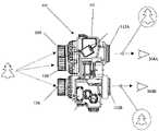
- FIG. 1is an isometric view of a fusion vision system consistent with one embodiment of the present invention.
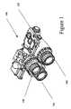
- FIG. 2is a top view of the fusion vision system of FIG. 1 .
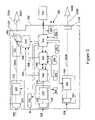
- FIG. 3is a block diagram of a fusion vision system consistent with another embodiment of the present invention.
- FIG. 3Ais a block diagram detailing interconnections between blocks shown in FIG. 3 .
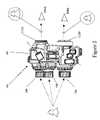
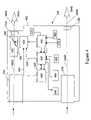
- FIG. 4is a block diagram of a fusion vision system consistent with another embodiment of the present invention.
- FIG. 5is a block diagram of a fusion vision system consistent with another embodiment of the present invention.
- FIGS. 1 and 2are views of a fusion vision system 100 consistent with one embodiment of the present invention.
- the fusion vision system 100may have a housing 102 , a first image intensification channel 104 , a second image intensification channel 106 , and a thermal channel 108 .
- the first and second image intensification channels 104 , 106may be configured to process information in a first range of wavelengths (for example the visible portion of the electromagnetic spectrum from approximately 400 nm to 900 nm) and the thermal channel 108 may be configured to process information in a second range of wavelengths (for example approximately 7,000 nm–14,000 nm).
- the low end and the high end of the ranges of wavelengthsmay vary without departing from the invention.
- the system 100may be mounted to a military helmet and powered by a removable battery pack 110 (see FIG. 3 ).
- An operatorcan view a scene through a right eyepiece 112 A and a left eyepiece 112 B.
- Information from the first image intensification (I 2 ) channel 104may be fused with the information from the thermal channel 108 and presented for viewing through the right eyepiece 112 A and information from the second I 2 channel 106 may be presented for viewing through the left eyepiece 112 B.
- the eyepieces 112 A, 112 Bmay have one or more ocular lenses.
- FIG. 3is a block diagram of a fusion vision system 300 consistent with another embodiment of the present invention.
- the electronics and opticsmay be housed in the housing 102 .
- Information from the first I 2 channel 104 and the thermal channel 108may be fused together and presented for viewing to an operator's right eye 304 A. Although reference will be made several times to the right eye, the fused image alternatively may be presented for viewing in the operator's left eye without departing from the present invention.
- the first I 2 channel 104 and the second I 2 channel 106may each have an objective focus 324 and an I 2 tube 322 for viewing a scene 308 .
- Suitable I 2 tubes 322may be Generation III tubes and are available from Northrop Grumman and ITT.
- Image 350 A from the first I 2 channel 104may be directed into a combiner optic 332 , for example a partially reflective beam splitter.
- the thermal channel 108may have an objective focus 330 and an infrared focal plane array 328 .
- the focal plane arraymay be a U7000J from DRS.
- An analog signal 352 from the focal plane array 328may be inputted into a circuit assembly 346 possibly having an analog circuit card assembly 338 , a digital circuit card assembly 340 , and a power and control circuit card assembly 342 .
- An analog video out signal 354 from the analog circuit card assembly 338may be inputted into a display 334 .
- a serial bus 358 coupled to the digital circuit card assembly 340may control the size, resolution, and offset of the display 334 .
- the display 334may be a miniature flat panel display, for example a yellow monochrome organic light emitting diode (OLED) microdisplay available from eMagin Corp.
- OLEDorganic light emitting diode
- the display 334may be used to present additional information needed by the operator.
- the additional informationmay include text, numbers, symbology, illustrations, and icons.
- the informationmay include commands from headquarters, operator global coordinates, distance to target, vehicle control/operating information, etc.
- I 2 image 350 A from the first channel 104 and image 356 from the display 334may be directed into the combiner optics 332 to generate a fused image 388 which may then be directed into the right eyepiece 112 A for presentation to the viewer's right eye 304 A as a first viewable image 390 A.
- I 2 image 350 B from the second I 2 channel 106may be directed into the left eyepiece 112 B for presentation to the viewer's left eye 304 B as a second viewable image 390 B.
- the fusion vision system 300may have an illumination LED 336 and a plurality of user actuatable actuators 370 , a programming port 384 , a digital data port 386 for transferring data, and a low battery signal generator 382 .
- the plurality of actuators 370may allow the operator to turn the system 300 on and off, scroll through menus viewable through the right eyepiece 112 A, and make a selection.
- the actuators 370may employ a silicone overlay over tactile dome switches. The overlay may be coupled to the housing 102 to seal out moisture and particulates and the dome switches may be coupled to the circuit assembly 346 .
- Eye Dominancetypically refers to the eye that the brain “prefers” or one that has stronger “processing” in the brain than the other. People usually have one eye that likes to “take over” when binocular vision is impaired, or one eye that is more sensitive to visual discrimination.
- Eye dominancemay be “forced” to a non-dominant eye by increasing the image size in the non-dominant eye over the image size in the dominant eye.
- a fusion vision system consistent with one embodiment the present inventionmay be used by operators with left or right eye dominance without departing from the invention.
- Right eyepiece 112 A and left eyepiece 112 Bmay be configured, for example by magnification or demagnification, to make fused viewable image 390 A appear larger than viewable image 390 B, for example by 0.5%–10%, more particularly 2–4%, and more particularly 3%. This may help the operator to more easily combine the image intensification information with the thermal information in their brain.
- scaling of the viewable imagesmay be done at the objective lenses 324 , 330 and/or at the display 334 , or a combination thereof.
- the fusion vision system 300may be called upon by the operator to view the scene 308 in a variety of adverse conditions, for example in very low light conditions, through smoke or heavy fog, and sand storms. In each of these conditions the operator may wish to rely more heavily on the first and second channels 104 , 106 (I 2 ) than the third channel 108 (thermal) and in other conditions the user may wish to rely more heavily on the third channel 108 than the first and second channels 104 , 106 .
- the fusion vision system 300may have one or more actuators to control the mix of information from the first and second channels 104 , 106 and the third channel 108 viewable through the eyepiece 112 A, 112 B.
- the viewable image 390 Acontains generally 100% image intensification information
- the viewable image 390 Acontains generally 100% thermal information
- the circuit assembly 346provides a mix of I 2 and thermal information.
- a mix actuator/s 360may be coupled to a microcontroller on the circuit assembly 346 that controls the gain of the I 2 tubes 322 and the contrast and brightness of the thermal image presented in the display 334 .
- the microcontrollermay control a digital potentiometer coupled to the gain control input of the I 2 tube.
- the fusion vision system 300may be configured to maintain a perceived brightness of the fused image 388 over a range of I 2 and thermal mixes.
- the fusion vision systemmay also include a parallax compensation circuit to compensate for the channels 104 , 106 , 108 being offset from each other.
- the longitudinal axis of the first channel 104 and the third channel 108may be factory aligned such that the thermal image 356 of a scene from the thermal channel 108 and I 2 image 350 A from the I 2 channel 104 are aligned on the image combiner 332 when the target is at the predetermine distance, for example infinity.
- the channelscan be offset in the horizontal direction, the vertical direction, or as shown in a combination.
- the processormay compensates by offsetting images up or down in the display 334 and when the channels are offset in the horizontal direction, the processor may compensates by offsetting images left or right in the display 334 to ensure thermal image 356 and the I 2 image 350 A are aligned when viewed through the eyepiece 112 A.
- a range findermay be utilized to determine the distance to target.
- the fusion vision system 300may accept inputs from a user regarding the distance to target.
- the inputmay be received through a near/far actuator or a menu selection.
- the fusion vision system 300may be designed so the operator selects the far mode when the object being viewed is greater than 10 meters away and the operator selects the near mode when the object being viewed is less than 10 meters away. Distances other than 10 meters may be chosen without departing from the invention.
- the fusion vision system 300may also incorporate multiple distance choices, for example close, less than 5 meters; mid range, 5–20 meters; and long range, greater than 20 meters, without departing from the invention.
- Fusion vision systemsmay be used at night with a weapon having an infrared laser illuminator aligned with the bore of the weapon.
- the fusion vision system 300allows the operator to aim and fire the weapon without having to look through a scope.
- the operatormay locate the target using the thermal channel information and align the weapon with the I 2 channel information.
- the I 2 information from the laser illuminatormay swamp the eyepiece making locating the target more difficult.
- the operatormay switch the fusion vision system into a “targeting mode” when trying to acquire a target.
- Targeting modemay be accessed through a dedicated actuator or through a menu.
- FIG. 4is a block diagram of a fused vision system 400 consistent with another embodiment of the present invention.
- the vision system 400may have a housing 402 , a first optical channel 404 , a second optical channel 406 , a display 434 , and an image combiner 432 .
- the first and second optical channels 404 , 406may be configured to image a scene in the visible spectrum (from approximately 400 nm to 900 nm) without an I 2 tube.
- First and second optical channels 404 , 406may include a series of lenses for magnifying a scene.
- the system 400may be hand-held or mounted to a military helmet and have an internal battery 410 or a removable battery pack.
- the display 434may display graphical information received from a circuit assembly 446 .
- the graphical informationmay include, but is not limited to, commands received from a remote location, operator global coordinates, distance to target, vehicle control/operating information, etc.
- the circuit assembly 446may have an analog circuit card assembly 438 , a digital circuit card assembly 440 , and a power and control circuit card assembly 442 .
- An analog video out signal 454 from the analog circuit card assembly 438may be inputted into the display 434 .
- a serial bus 458 coupled to the digital circuit card assembly 440may control the size, resolution, and offset of the display 434 .
- the display 434may be a miniature flat panel display, for example a yellow monochrome organic light emitting diode (OLED) microdisplay available from eMagin Corp.
- the circuit assembly 446may receive information from an on board range finder 460 or a global positioning system or compass 480 .
- the circuit assembly 446may also receive information through a receiver 484 from a remote location, for example from another soldier, an aircraft, or headquarters.
- the circuit assemblymay also transmit information through a transmitter 486 to a remote location.
- the fused vision system 400may also have a plurality of user actuatable actuators 470 that may allow the operator to turn the system on and off, scroll through menus viewable through the right eyepiece 112 A, and make a selection.
- Image 450 A from the first optical channel 404may be fused with graphical information 456 and presented as a fused image 488 which may then be directed into the right eyepiece 112 A for presentation to the viewer's right eye 304 A as a first viewable image 490 A.
- Information 450 B from the second optical channel 406may be directed into the left eyepiece 112 B for presentation to the viewer's left eye 304 B as a second viewable image 490 B.
- the image 450 A from the first optical channel 404 and the graphical information 456may be fused in the image combiner 434 , for example a partially reflective beam splitter.
- the fused viewable imagealternatively may be presented for viewing in the operator's left eye without departing from the present invention.
- the eyepieces 112 A, 112 Bmay have one or more ocular lenses.
- Right eyepiece 112 A and left eyepiece 1121 Bmay be configured, for example by magnification or demagnification, to make the first (fused) viewable image 490 A appear larger than the second (non-fused) viewable image 490 B, for example by 0.5%–10%, more particularly 2–4%, and more particularly 3%. This may help the operator to more easily combine the image intensification information with the thermal information in their brain.
- scaling of the viewable imagesmay be done in the first and second optical channels 404 , 406 and/or at the display 434 , or a combination thereof.
- FIG. 5is a block diagram of a fused vision system 500 .
- the electronics and opticsmay be housed in a housing 502 , which can be mounted to a military helmet, and are powered by batteries.
- Information from an image intensification (I 2 ) channel 506 and a thermal channel 508are fused together for viewing by an operator through one or more eyepieces 510 .
- the eyepieces 510have one or more ocular lenses for magnifying and/or focusing the fused image.
- the I 2 channel 506is configured to process information in a first range of wavelengths (the visible portion of the electromagnetic spectrum from 400 nm to 900 nm) and the thermal channel 508 is configured to process information in a second range of wavelengths (7,000 nm–14,000 nm).
- the I 2 channel 506has an objective focus 512 and an I 2 tube 514 and the thermal channel 508 has an objective focus 516 and an infrared sensor 518 , for example a focal plane array.
- the I 2 informationmay be coupled to a charge-coupled device (CCD) and electronics 540 and the thermal information may be coupled to signal processing electronics 544 .
- the output from the CCD and electronics 540may be inputted into both the mixing/display electronics 542 and a first display 546 A for viewing through eyepieces 510 A.
- the output from the signal processing electronics 544may be inputted into mixing/display electronics 542 .
- the fused analog video signal output of the mixing/display electronics 542may then be coupled to a second display 546 B for viewing through eyepieces 510 BA.
- the mixing/display electronics 542may be configured to modify the size of the fused image so that the fused image appears larger in the second eyepiece 510 B than the non-fused image appears in the first eyepiece 510 A.
- an ocular lens assembly in one of the first and second eyepieces 510 A, 510 Bmay modify the size of the fused image so that the fused image appears larger in the second eyepiece 510 B than the non-fused image appears in the first eyepiece 510 A.
- a fusion vision systemmay include a housing, a first and a second channel for processing information in a first range of wavelengths, a third channel for processing information in a second range of wavelengths, an image combiner for combining the information from the first channel and the third channel to generate a fused image.
- a first eyepiecebeing aligned with the fused image and a second eyepiece being aligned with the second channel such that the fused image viewed through the first eyepiece is larger than an image viewed through the second eyepiece.
- a method of displaying information representative of a scenemay include the steps of: acquiring information representative of the scene from a first and a second channel configured to process information in a first range of wavelengths; acquiring information representative of the scene from a third channel configured to process information in a second range of wavelengths; combining the acquired information from the first and third channels into a fused image; displaying the fused image in a first eyepiece at a first size, and displaying the acquired information from the second channel in a second eyepiece such that the image viewable through the second eyepiece is smaller than the fused image viewable through the first eyepiece.
- a binocular vision systemmay include a housing, first and second channels coupled to the housing and configured to image a scene in a first range of wavelengths, a display for displaying information, a combiner for combining an image from the first channel with information from the display to generate a fused image, and a first and a second eyepiece.
- a binocular vision systemmay include a housing, a first channel configured to image a scene in a first range of wavelengths, a second channel configured to image a scene in a second range of wavelengths, a combiner configured to generate a fused image from an image from the first channel with an image from the second channel, a first display aligned with a first eyepiece for projecting the fused image, and a second display aligned with a second eyepiece for projecting the image from the first channel.
- the systemconfigured such that the fused image when viewed through the first eyepiece is larger than the image from the first channel when viewed through the second eyepiece.
Landscapes
- Physics & Mathematics (AREA)
- Astronomy & Astrophysics (AREA)
- General Physics & Mathematics (AREA)
- Optics & Photonics (AREA)
Abstract
Description
Claims (28)
Priority Applications (2)
| Application Number | Priority Date | Filing Date | Title |
|---|---|---|---|
| US11/272,123US7158296B1 (en) | 2004-07-02 | 2005-11-10 | Vision system with eye dominance forced to fusion channel |
| US11/608,954US7746551B2 (en) | 2004-11-12 | 2006-12-11 | Vision system with eye dominance forced to fusion channel |
Applications Claiming Priority (5)
| Application Number | Priority Date | Filing Date | Title |
|---|---|---|---|
| US58532704P | 2004-07-02 | 2004-07-02 | |
| US58969304P | 2004-07-21 | 2004-07-21 | |
| US62719704P | 2004-11-12 | 2004-11-12 | |
| US64509705P | 2005-01-20 | 2005-01-20 | |
| US11/272,123US7158296B1 (en) | 2004-07-02 | 2005-11-10 | Vision system with eye dominance forced to fusion channel |
Related Child Applications (1)
| Application Number | Title | Priority Date | Filing Date |
|---|---|---|---|
| US11/608,954Continuation-In-PartUS7746551B2 (en) | 2004-11-12 | 2006-12-11 | Vision system with eye dominance forced to fusion channel |
Publications (1)
| Publication Number | Publication Date |
|---|---|
| US7158296B1true US7158296B1 (en) | 2007-01-02 |
Family
ID=37592325
Family Applications (1)
| Application Number | Title | Priority Date | Filing Date |
|---|---|---|---|
| US11/272,123ActiveUS7158296B1 (en) | 2004-07-02 | 2005-11-10 | Vision system with eye dominance forced to fusion channel |
Country Status (1)
| Country | Link |
|---|---|
| US (1) | US7158296B1 (en) |
Cited By (23)
| Publication number | Priority date | Publication date | Assignee | Title |
|---|---|---|---|---|
| US20060146169A1 (en)* | 2005-01-03 | 2006-07-06 | Yosef Segman | Electronic viewing device |
| US20070016425A1 (en)* | 2005-07-12 | 2007-01-18 | Koren Ward | Device for providing perception of the physical environment |
| US20070103773A1 (en)* | 2004-11-12 | 2007-05-10 | Schwartz Ii Sheldon | Vision System with Eye Dominance Forced to Fusion Channel |
| US20070229943A1 (en)* | 2006-03-31 | 2007-10-04 | Robert Tartaglia | Optical and infrared periscope with display monitor |
| US20090010635A1 (en)* | 2007-07-06 | 2009-01-08 | Flir Systems Ab | Camera and method for use with camera |
| USD586874S1 (en)* | 2006-01-31 | 2009-02-17 | Insight Technology Incorporated | Weapon aiming device |
| US20100014166A1 (en)* | 2008-06-23 | 2010-01-21 | Vectronix Ag | Observation device |
| US20100277595A1 (en)* | 2005-10-18 | 2010-11-04 | Reed Matthew W | Clip-on infrared imager |
| USD641826S1 (en)* | 2010-04-07 | 2011-07-19 | Gs Development Ab | Sight without kick stop |
| US20130293531A1 (en)* | 2012-05-01 | 2013-11-07 | Microsoft Corporation | User perception of visual effects |
| USD696377S1 (en)* | 2012-01-03 | 2013-12-24 | Laser Devices, Inc. | Dual beam aiming laser |
| US8736967B1 (en) | 2010-11-19 | 2014-05-27 | SA Photonics, Inc. | Anamorphic eyepiece |
| US20140226213A1 (en)* | 2013-02-13 | 2014-08-14 | Exelis, Inc. | Removable display for optical device |
| US20140267757A1 (en)* | 2013-03-15 | 2014-09-18 | Fluke Corporation | Parallax correction in thermal imaging cameras |
| WO2015085984A1 (en)* | 2013-12-13 | 2015-06-18 | Steiner-Optik Gmbh | Magnifying optical device |
| USD733832S1 (en)* | 2014-01-13 | 2015-07-07 | Leupold & Stevens, Inc. | Sighting device |
| US9618746B2 (en) | 2010-11-19 | 2017-04-11 | SA Photonics, Inc. | High resolution wide field of view digital night vision system |
| US9651786B1 (en) | 2015-05-05 | 2017-05-16 | SA Photonics, Inc. | Systems and methods for augmented reality devices with light security |
| USD790654S1 (en) | 2015-05-23 | 2017-06-27 | Leupold & Stevens, Inc. | Bezel for a sighting device |
| USD810854S1 (en) | 2015-05-23 | 2018-02-20 | Leupold & Stevens, Inc. | Sighting device |
| US11204649B2 (en) | 2020-01-30 | 2021-12-21 | SA Photonics, Inc. | Head-mounted display with user-operated control |
| US11378801B1 (en) | 2017-05-25 | 2022-07-05 | Vision Products, Llc | Wide field of view night vision system |
| WO2022200836A1 (en)* | 2021-03-26 | 2022-09-29 | Uab "Yukon Advanced Optics Worldwide" | Apparatus and method for combined use of two independent monoculars |
Citations (32)
| Publication number | Priority date | Publication date | Assignee | Title |
|---|---|---|---|---|
| US2256587A (en)* | 1937-06-10 | 1941-09-23 | Dartmouth College | Correcting ocular defects |
| US4445766A (en)* | 1980-06-16 | 1984-05-01 | Orinox Co., Ltd. | Binoculars with a detachable small camera |
| US4468101A (en) | 1981-05-29 | 1984-08-28 | Marconi Avionics Limited | Night vision goggles |
| US4653879A (en) | 1985-03-01 | 1987-03-31 | Fjw Industries, Inc. | Compact see-through night vision goggles |
| US4915487A (en) | 1989-02-01 | 1990-04-10 | Systems Research Laboratories | Heads up display for night vision goggle |
| US5079416A (en) | 1987-10-27 | 1992-01-07 | Night Vision General Partnership | Compact see-through night vision goggles |
| US5229598A (en) | 1992-01-29 | 1993-07-20 | Night Vision General Partnership | Night vision goggles having enlarged field of view and interchangeable optics |
| US5254852A (en) | 1992-05-28 | 1993-10-19 | Night Vision General Partnership | Helmet-mounted night vision system and secondary imager |
| US5282082A (en)* | 1990-07-31 | 1994-01-25 | Thomson Trt Defense | Day-and-night optical observation device |
| US5416315A (en) | 1994-01-24 | 1995-05-16 | Night Vision General Partnership | Visor-mounted night vision visor |
| US5483336A (en)* | 1992-10-30 | 1996-01-09 | Vx Optronics | Self correcting stereoscopic auto-rangefinder |
| US5943174A (en) | 1998-06-16 | 1999-08-24 | Itt Manufacturing Enterprises, Inc. | Night vision monocular device |
| US6061182A (en) | 1996-11-21 | 2000-05-09 | Vectop Ltd. | Combiner for superimposing a display image on to an image of an external scene |
| US6081094A (en) | 1997-07-17 | 2000-06-27 | Itt Manufacturing Enterprises, Inc. | Clip-on power source for an aviator's night vision imaging system |
| US6201641B1 (en) | 1996-12-20 | 2001-03-13 | Night Vision Corporation | Panoramic night vision goggles |
| US6219250B1 (en) | 1996-04-03 | 2001-04-17 | Itt Manufacturing Enterprises | Night vision binoculars |
| US6288386B1 (en) | 1998-10-28 | 2001-09-11 | Itt Manufacturing Enterprises Inc. | Circuit having a flexible printed circuit board for electronically controlling a night vision device and night vision device including the same |
| US6349001B1 (en)* | 1997-10-30 | 2002-02-19 | The Microoptical Corporation | Eyeglass interface system |
| US20020030163A1 (en)* | 2000-08-09 | 2002-03-14 | Zhang Evan Y.W. | Image intensifier and LWIR fusion/combination system |
| US6369941B2 (en)* | 2000-02-15 | 2002-04-09 | Leica Geosystems Ag | Device with night vision capability |
| US6379009B1 (en)* | 1996-04-24 | 2002-04-30 | James L. Fergason | Conjugate optics projection display with image enhancement |
| US6456497B1 (en) | 1998-03-12 | 2002-09-24 | Itt Manufacturing Enterprises, Inc. | Night vision binoculars |
| US6462894B1 (en) | 2001-02-16 | 2002-10-08 | Insight Technology, Inc. | Monocular mounting for four-tube panoramic night vision goggle having multi-function adjustment control |
| US6462867B2 (en) | 2001-02-16 | 2002-10-08 | Insight Technology, Inc. | Monocular mounting for multi-channel panoramic night vision goggle having an angled mounting shoe |
| US6469828B2 (en) | 2001-02-16 | 2002-10-22 | Insight Technology, Inc. | Panoramic night vision goggle having multi-channel monocular assemblies with a modified eyepiece |
| US6493137B1 (en) | 2001-02-16 | 2002-12-10 | Insight Technology, Inc. | Monocular mounting for multi-channel panoramic night vision goggle having a hot shoe connector |
| US6560029B1 (en) | 2001-12-21 | 2003-05-06 | Itt Manufacturing Enterprises, Inc. | Video enhanced night vision goggle |
| US6662370B1 (en) | 2002-01-11 | 2003-12-16 | Itt Manufacturing Enterprises, Inc. | Night vision device helmet mount |
| US6687053B1 (en) | 2001-09-27 | 2004-02-03 | Itt Manufacturing Enterprises, Inc. | Binocular device and method utilizing monocular devices |
| US6903811B2 (en)* | 2003-08-11 | 2005-06-07 | Kamakura Koki Co., Ltd. | Rangefinder binoculars |
| US6977776B2 (en)* | 2001-07-06 | 2005-12-20 | Carl Zeiss Ag | Head-mounted optical direct visualization system |
| US20060048286A1 (en)* | 2003-01-27 | 2006-03-09 | Giuseppe Donato | Helmet for displaying environmental images in critical environments |
- 2005
- 2005-11-10USUS11/272,123patent/US7158296B1/enactiveActive
Patent Citations (33)
| Publication number | Priority date | Publication date | Assignee | Title |
|---|---|---|---|---|
| US2256587A (en)* | 1937-06-10 | 1941-09-23 | Dartmouth College | Correcting ocular defects |
| US4445766A (en)* | 1980-06-16 | 1984-05-01 | Orinox Co., Ltd. | Binoculars with a detachable small camera |
| US4468101A (en) | 1981-05-29 | 1984-08-28 | Marconi Avionics Limited | Night vision goggles |
| US4653879A (en) | 1985-03-01 | 1987-03-31 | Fjw Industries, Inc. | Compact see-through night vision goggles |
| US5079416A (en) | 1987-10-27 | 1992-01-07 | Night Vision General Partnership | Compact see-through night vision goggles |
| US4915487A (en) | 1989-02-01 | 1990-04-10 | Systems Research Laboratories | Heads up display for night vision goggle |
| US5282082A (en)* | 1990-07-31 | 1994-01-25 | Thomson Trt Defense | Day-and-night optical observation device |
| US5229598A (en) | 1992-01-29 | 1993-07-20 | Night Vision General Partnership | Night vision goggles having enlarged field of view and interchangeable optics |
| US5254852A (en) | 1992-05-28 | 1993-10-19 | Night Vision General Partnership | Helmet-mounted night vision system and secondary imager |
| US5483336A (en)* | 1992-10-30 | 1996-01-09 | Vx Optronics | Self correcting stereoscopic auto-rangefinder |
| US5416315A (en) | 1994-01-24 | 1995-05-16 | Night Vision General Partnership | Visor-mounted night vision visor |
| US6219250B1 (en) | 1996-04-03 | 2001-04-17 | Itt Manufacturing Enterprises | Night vision binoculars |
| US6379009B1 (en)* | 1996-04-24 | 2002-04-30 | James L. Fergason | Conjugate optics projection display with image enhancement |
| US6061182A (en) | 1996-11-21 | 2000-05-09 | Vectop Ltd. | Combiner for superimposing a display image on to an image of an external scene |
| US6201641B1 (en) | 1996-12-20 | 2001-03-13 | Night Vision Corporation | Panoramic night vision goggles |
| US6081094A (en) | 1997-07-17 | 2000-06-27 | Itt Manufacturing Enterprises, Inc. | Clip-on power source for an aviator's night vision imaging system |
| US6349001B1 (en)* | 1997-10-30 | 2002-02-19 | The Microoptical Corporation | Eyeglass interface system |
| US6456497B1 (en) | 1998-03-12 | 2002-09-24 | Itt Manufacturing Enterprises, Inc. | Night vision binoculars |
| US5943174A (en) | 1998-06-16 | 1999-08-24 | Itt Manufacturing Enterprises, Inc. | Night vision monocular device |
| US6288386B1 (en) | 1998-10-28 | 2001-09-11 | Itt Manufacturing Enterprises Inc. | Circuit having a flexible printed circuit board for electronically controlling a night vision device and night vision device including the same |
| US6369941B2 (en)* | 2000-02-15 | 2002-04-09 | Leica Geosystems Ag | Device with night vision capability |
| US20020030163A1 (en)* | 2000-08-09 | 2002-03-14 | Zhang Evan Y.W. | Image intensifier and LWIR fusion/combination system |
| US6462894B1 (en) | 2001-02-16 | 2002-10-08 | Insight Technology, Inc. | Monocular mounting for four-tube panoramic night vision goggle having multi-function adjustment control |
| US6462867B2 (en) | 2001-02-16 | 2002-10-08 | Insight Technology, Inc. | Monocular mounting for multi-channel panoramic night vision goggle having an angled mounting shoe |
| US6469828B2 (en) | 2001-02-16 | 2002-10-22 | Insight Technology, Inc. | Panoramic night vision goggle having multi-channel monocular assemblies with a modified eyepiece |
| US6493137B1 (en) | 2001-02-16 | 2002-12-10 | Insight Technology, Inc. | Monocular mounting for multi-channel panoramic night vision goggle having a hot shoe connector |
| US6977776B2 (en)* | 2001-07-06 | 2005-12-20 | Carl Zeiss Ag | Head-mounted optical direct visualization system |
| US6788459B2 (en) | 2001-09-27 | 2004-09-07 | Itt Manufacturing Enterprises, Inc. | Binocular method utilizing monocular devices |
| US6687053B1 (en) | 2001-09-27 | 2004-02-03 | Itt Manufacturing Enterprises, Inc. | Binocular device and method utilizing monocular devices |
| US6560029B1 (en) | 2001-12-21 | 2003-05-06 | Itt Manufacturing Enterprises, Inc. | Video enhanced night vision goggle |
| US6662370B1 (en) | 2002-01-11 | 2003-12-16 | Itt Manufacturing Enterprises, Inc. | Night vision device helmet mount |
| US20060048286A1 (en)* | 2003-01-27 | 2006-03-09 | Giuseppe Donato | Helmet for displaying environmental images in critical environments |
| US6903811B2 (en)* | 2003-08-11 | 2005-06-07 | Kamakura Koki Co., Ltd. | Rangefinder binoculars |
Non-Patent Citations (54)
| Title |
|---|
| Insight Technology, Inc. AN/PSQ-18A M203 Day Night Sight NSN 1010-01-516-0953. Copyright 2003. |
| Insight Technology, Inc. AN/TVS-5 Advanced Crew-served Weapon Sight (ACSWS). Copyright 2000. |
| Insight Technology, Inc. Close-Quarter Battle Sight Short Range CQB-001C. Copyright 2004. Believed by applicant to be representative of prior art. |
| Insight Technology, Inc. Laser Aiming Module (LAM) An/PEQ-6. Copyright 1997. |
| Insight Technology, Inc. M3X Tactical Illuminator Copyright 2003. |
| Insight Technology, Inc. Medium Powered Laser Illuminator (MLPI) High Powered laser Illuminator (HPLI) AN/PEQ-4. Copyright 1998. |
| Insight Technology, Inc. Muti-use Mini-Monocular. Copyright 2002. |
| Insight Technology, Inc. Thermal Goggle System TGS-1000. Copyright 1998. |
| Insight Technology, Inc. U.S. Military AN/PVS-7D Night Vision Goggles. Copyright 2002. |
| Insight Technology, Inc. U.S. Military M30 Boresighting Equipment NSN:4933-01-394-7781. Copyright 1998. |
| Insight Technology, Inc. U.S. Military TS-4348/UV, Night Vision Device Test Set. Copyright 1998. |
| Insight Technology, Inc. U.S. Militatry AN/PEM-1 Laser Borelight System. Copyright 1999. |
| Insight Technology, Inc. U.S. Militatry AN/PEQ-2 &2A Infrared Target Pointer/Illuminator/Aiming Laser. NSN: 5855-01-422-5253 & NSN: 5855-01-447-8992. Copyright 1998. |
| Insight Technology, Inc. U.S. Militatry AN/PEQ-5 Carbine Visible Laser (CVL). Copoyright 1997. |
| ITT Industries, Binocular Night Vision Goggle, Ground Gen 3, AN/PVS-23 (F5050). 2 Pages. Copyright 2004. Believed by Applicant to be representative of prior art. |
| ITT Industries, Monocular Night Vision Device (MNVD) Generation 3, F6015 Series. 2 Pages, Dated Sep. 2003. Believed by Applicant to be representative of prior art. |
| Martin S. Banks, Tandra Ghose, James M. Hillis, Relative Image Size, Not Eye Position, Determines Eye Dominance Switches. |
| NIGHTVISIONWEB.COM, Aurora,high grade compact Night Vision Scope w/IR. 1 Page. Copyright 2000-2005 Printed Jul. 14, 2005. |
| NIGHTVISIONWEB.COM, Budget Night Vision Scope NZT-1 1 Page. Copyright 2000-2005 Printed Jul. 14, 2005. |
| NIGHTVISIONWEB.COM, Compact Night Vision Goggles ANVS-3103 2 Pages. Copyright 2000-2004 Printed Jul. 14, 2005. |
| NIGHTVISIONWEB.COM, Deluxe Night Vision Goggles ANVS-3107 2 Pages. Copyright 2000-2004 Printed Jul. 14, 2005. |
| NIGHTVISIONWEB.COM, Gen 2+ /3 Night Vision Goggles D-221G/321G 2 Pages. Copyright 2000-2005 Printed Jul. 14, 2005. |
| NIGHTVISIONWEB.COM, Helios 101, high grade Hight Vision Scope w/IR 1 Page. Copyright 2000-2005 Printed Jul. 14, 2005. |
| NIGHTVISIONWEB.COM, Helios 112, waterproof Night Vision Scope w/IR 1 Page. Copyright 2000-2005 Printed Jul. 14, 2005. |
| NIGHTVISIONWEB.COM, High Grade Vision Scope MO2-1 2 Pages. Copyright 2000-2005 Printed Jul. 14, 2005. |
| NIGHTVISIONWEB.COM, Long Range Night Vision monocular Argus-M4 w/IR Illum. 2 Pages. Copyright 2000-2005 Printed Jul. 14, 2005. |
| NIGHTVISIONWEB.COM, MO-4X series Night Vision Scopes 2 Pages. Copyright 2000-2005 Printed Jul. 14, 2005. |
| NIGHTVISIONWEB.COM, Multitask Gen 2+ Night Vision Scope Model NVMT 2x24 G2 2 Pages. Copyright 2000-2005 Printed Jul. 14, 2005. |
| NIGHTVISIONWEB.COM, Multitask Night Vision Scope, Model NVMT 2x24. 2 Pages. Copyright 2000-2005 Printed Jul. 14, 2005. |
| NIGHTVISIONWEB.COM, Multitask Night Vision Scope, Model NVMT 3x42. 2 Pages. Copyright 2000-2005 Printed Jul. 14, 2005. |
| NIGHTVISIONWEB.COM, Night Quest 5001 2 Pages. Copyright 2000-2005 Printed Jul. 14, 2005. |
| NIGHTVISIONWEB.COM, Night Quest 6010,Night Quest 6015, Night Quest PVS-14 2 Pages. Copyright 2000-2005 Printed Jul. 14, 2005. |
| NIGHTVISIONWEB.COM, Night Storm, Waterproof Night Vision Scope 2 Pages. Copyright 2000-2005 Printed Jul. 14, 2005. |
| NIGHTVISIONWEB.COM, Night Vision Goggles Argus w/IR Illuminator 2 Pages. Copyright 2000-2004 Printed Jul. 14, 2005. |
| NIGHTVISIONWEB.COM, Night Vision Goggles Night Cougar 1 Page. Copyright 2000-2005 Printed Jul. 14, 2005. |
| NIGHTVISIONWEB.COM, Night Vision Goggles Viper 2 Pages. Copyright 2000-2005 Printed Jul. 14, 2005. |
| NIGHTVISIONWEB.COM, Night Vision Mono Goggles Argus-M w/IR Illuminator, 2 Pages. Copyright 2000-2005 Printed Jul. 14, 2005. |
| NIGHTVISIONWEB.COM, Night Vision Monocular ANVS-1330 2 Pages. Copyright 2000-2005 Printed Jul. 14, 2005. |
| NIGHTVISIONWEB.COM, Night Vision Monocular PS-14 2 Pages. Copyright 2000-2005 Printed Jul. 14, 2005. |
| NIGHTVISIONWEB.COM, NVG7-2/3 Night Vision Goggle 2 Pages. Copyright 2000-2005 Printed Jul. 14, 2005. |
| NIGHTVISIONWEB.COM, PRO Night Vision monocular Dipol-111 w/IR Illuminator 2 Pages. Copyright 2000-2005 Printed Jul. 14, 2005. |
| NIGHTVISIONWEB.COM, PRO Series Night Vision Goggles ANVS-3105 2 Pages. Copyright 2000-2004 Printed Jul. 14, 2005. |
| NIGHTVISIONWEB.COM, PVS-7 Night Vision Goggles 2 Pages. Copyright 2000-2005 Printed Jul. 14, 2005. |
| NIGHTVISIONWEB.COM, Tactical Night Vision Scope ANVS-1344/Mini Monocular 2 Pages. Copyright 2000-2005 Printed Jul. 14, 2005. |
| Northrop Grumman, Monocular Night Vision Device AN/PVS-14 2 Pages. Believed by Applicant to be representative of prior art. |
| Northrop Grumman, Submersible Binocular Night Vision System (BVNS) AN/PVS-15.2 Pages. Believed by Applicant to be representative of prior art. |
| Northrop Grumman, Submersible Monocular Night Vision System, AN/PVS-18. 2 Pages. Believed by Applicant to be representative of prior art. |
| Photograph of Insight Technology, Inc. product CNVD. Beleived by applicant to be representative of prior art. |
| Photograph of Insight Technology, Inc. product ENVG, Phase 1 Believed by Applicant to be representative of prior art. |
| Photograph of Insight Technology, Inc. product ENVG, Phase 2 Believed by Applicant to be representative of prior art. |
| Photograph of Insight Technology, Inc. product OFG. Believed by applicant to be representative of prior art. |
| Photograph of Insight Technology, Inc. product PNVG. Believed by applicant to be representative of prior art. |
| Science Direct, Vision Research, vol. 44, Issue 3, Feb. 2004, 6 Pages. |
| Website www.atncorp.com/ProfessionalMilitaryNightVision printed May 16, 2005. |
Cited By (35)
| Publication number | Priority date | Publication date | Assignee | Title |
|---|---|---|---|---|
| US20070103773A1 (en)* | 2004-11-12 | 2007-05-10 | Schwartz Ii Sheldon | Vision System with Eye Dominance Forced to Fusion Channel |
| US7746551B2 (en)* | 2004-11-12 | 2010-06-29 | L-3 Insight Technology Incorporated | Vision system with eye dominance forced to fusion channel |
| US7535498B2 (en)* | 2005-01-03 | 2009-05-19 | Cnoga Medical Ltd. | Electronic viewing device |
| US20060146169A1 (en)* | 2005-01-03 | 2006-07-06 | Yosef Segman | Electronic viewing device |
| US20070016425A1 (en)* | 2005-07-12 | 2007-01-18 | Koren Ward | Device for providing perception of the physical environment |
| US7842921B2 (en)* | 2005-10-18 | 2010-11-30 | L-3 Insight Technology Incorporated | Clip-on infrared imager |
| US20100277595A1 (en)* | 2005-10-18 | 2010-11-04 | Reed Matthew W | Clip-on infrared imager |
| USD586874S1 (en)* | 2006-01-31 | 2009-02-17 | Insight Technology Incorporated | Weapon aiming device |
| US20070229943A1 (en)* | 2006-03-31 | 2007-10-04 | Robert Tartaglia | Optical and infrared periscope with display monitor |
| US7880962B2 (en)* | 2006-03-31 | 2011-02-01 | Robert Tartaglia | Optical and infrared periscope with display monitor |
| CN101796818B (en)* | 2007-07-06 | 2012-05-23 | 前视红外系统股份公司 | Camera and method for aligning IR images and visible light images |
| WO2009008812A1 (en)* | 2007-07-06 | 2009-01-15 | Flir Systems Ab | Camera and method for aligning ir images and visible light images |
| US7809258B2 (en) | 2007-07-06 | 2010-10-05 | Flir Systems Ab | Camera and method for use with camera |
| US20090010635A1 (en)* | 2007-07-06 | 2009-01-08 | Flir Systems Ab | Camera and method for use with camera |
| US20100014166A1 (en)* | 2008-06-23 | 2010-01-21 | Vectronix Ag | Observation device |
| US7978415B2 (en)* | 2008-06-23 | 2011-07-12 | Vectronix Ag | Observation device |
| USD641826S1 (en)* | 2010-04-07 | 2011-07-19 | Gs Development Ab | Sight without kick stop |
| US9618746B2 (en) | 2010-11-19 | 2017-04-11 | SA Photonics, Inc. | High resolution wide field of view digital night vision system |
| US8736967B1 (en) | 2010-11-19 | 2014-05-27 | SA Photonics, Inc. | Anamorphic eyepiece |
| US11448881B2 (en) | 2010-11-19 | 2022-09-20 | Vision Products, Llc | High resolution wide field of view digital night vision system |
| US10473931B2 (en) | 2010-11-19 | 2019-11-12 | SA Photonics, Inc. | High resolution wide field of view digital night vision system |
| USD696377S1 (en)* | 2012-01-03 | 2013-12-24 | Laser Devices, Inc. | Dual beam aiming laser |
| US20130293531A1 (en)* | 2012-05-01 | 2013-11-07 | Microsoft Corporation | User perception of visual effects |
| US20140226213A1 (en)* | 2013-02-13 | 2014-08-14 | Exelis, Inc. | Removable display for optical device |
| US20140267757A1 (en)* | 2013-03-15 | 2014-09-18 | Fluke Corporation | Parallax correction in thermal imaging cameras |
| TWI660197B (en)* | 2013-12-13 | 2019-05-21 | 德商斯坦納光學公司 | Magnifying optical device |
| WO2015085984A1 (en)* | 2013-12-13 | 2015-06-18 | Steiner-Optik Gmbh | Magnifying optical device |
| USD733832S1 (en)* | 2014-01-13 | 2015-07-07 | Leupold & Stevens, Inc. | Sighting device |
| US9651786B1 (en) | 2015-05-05 | 2017-05-16 | SA Photonics, Inc. | Systems and methods for augmented reality devices with light security |
| US10451878B2 (en) | 2015-05-05 | 2019-10-22 | SA Photonics, Inc. | Systems and methods for augmented reality devices with light security |
| USD790654S1 (en) | 2015-05-23 | 2017-06-27 | Leupold & Stevens, Inc. | Bezel for a sighting device |
| USD810854S1 (en) | 2015-05-23 | 2018-02-20 | Leupold & Stevens, Inc. | Sighting device |
| US11378801B1 (en) | 2017-05-25 | 2022-07-05 | Vision Products, Llc | Wide field of view night vision system |
| US11204649B2 (en) | 2020-01-30 | 2021-12-21 | SA Photonics, Inc. | Head-mounted display with user-operated control |
| WO2022200836A1 (en)* | 2021-03-26 | 2022-09-29 | Uab "Yukon Advanced Optics Worldwide" | Apparatus and method for combined use of two independent monoculars |
Similar Documents
| Publication | Publication Date | Title |
|---|---|---|
| US7158296B1 (en) | Vision system with eye dominance forced to fusion channel | |
| US7746551B2 (en) | Vision system with eye dominance forced to fusion channel | |
| US7864432B2 (en) | Fusion night vision system | |
| US7541581B2 (en) | Clip-on infrared imager | |
| US9323061B2 (en) | Viewer with display overlay | |
| US6456261B1 (en) | Head/helmet mounted passive and active infrared imaging system with/without parallax | |
| US11206341B2 (en) | Fusion night vision system | |
| EP3401631B1 (en) | Thermal reflex sight | |
| US7813037B2 (en) | Day/night-vision device | |
| US20120007987A1 (en) | Optical system with automatic switching between operation in daylight and thermovision modes | |
| US20070228259A1 (en) | System and method for fusing an image | |
| US20120019700A1 (en) | Optical system with automatic mixing of daylight and thermal vision digital video signals | |
| US10425540B2 (en) | Method and system for integrated optical systems | |
| KR102520544B1 (en) | Sights and firearms for day and night use | |
| US10520724B2 (en) | Multi-wavelength head up display systems and methods | |
| US8860831B1 (en) | Brightness tracking light sensor | |
| Gerken et al. | Military reconnaissance platform for the spectral range from the visible to the MWIR | |
| US9191585B2 (en) | Modular night-vision system with fused optical sensors | |
| GB2468948A (en) | Optical bypass device and thermal imaging attachment for an image intensifier | |
| EP2612191B1 (en) | Indicator systems in night vision devices | |
| US9426389B1 (en) | Second imaging device adaptable for use with first imaging device and method for using same | |
| US20240295382A1 (en) | Imaging apparatus with thermal augmentation | |
| CN216291220U (en) | Monocular binocular night vision device | |
| US20070013997A1 (en) | Day-night vision device | |
| GB2538256A (en) | Optical data insertion device |
Legal Events
| Date | Code | Title | Description |
|---|---|---|---|
| AS | Assignment | Owner name:INSIGHT TECHNOLOGY, INCORPORATED, NEW HAMPSHIRE Free format text:ASSIGNMENT OF ASSIGNORS INTEREST;ASSIGNORS:SCHWARTZ, II, SHELDON;REED, MATTHEW W.;REEL/FRAME:017142/0483 Effective date:20051110 | |
| STCF | Information on status: patent grant | Free format text:PATENTED CASE | |
| FPAY | Fee payment | Year of fee payment:4 | |
| AS | Assignment | Owner name:L-3 INSIGHT TECHNOLOGY INCORPORATED, NEW HAMPSHIRE Free format text:CHANGE OF NAME;ASSIGNOR:INSIGHT TECHNOLOGY INCORPORATED;REEL/FRAME:024785/0308 Effective date:20100415 | |
| AS | Assignment | Owner name:L-3 COMMUNICATIONS INSIGHT TECHNOLOGY INCORPORATED Free format text:ASSIGNMENT OF ASSIGNORS INTEREST;ASSIGNOR:L-3 INSIGHT TECHNOLOGY INCORPORATED;REEL/FRAME:027052/0397 Effective date:20110929 | |
| FPAY | Fee payment | Year of fee payment:8 | |
| MAFP | Maintenance fee payment | Free format text:PAYMENT OF MAINTENANCE FEE, 12TH YEAR, LARGE ENTITY (ORIGINAL EVENT CODE: M1553) Year of fee payment:12 |