US7158115B2 - Spring system for re-centering a movable object - Google Patents
Spring system for re-centering a movable objectDownload PDFInfo
- Publication number
- US7158115B2 US7158115B2US10/723,596US72359603AUS7158115B2US 7158115 B2US7158115 B2US 7158115B2US 72359603 AUS72359603 AUS 72359603AUS 7158115 B2US7158115 B2US 7158115B2
- Authority
- US
- United States
- Prior art keywords
- puck
- motion
- field
- boundary
- springs
- Prior art date
- Legal status (The legal status is an assumption and is not a legal conclusion. Google has not performed a legal analysis and makes no representation as to the accuracy of the status listed.)
- Expired - Fee Related, expires
Links
Images


Classifications
- G—PHYSICS
- G06—COMPUTING OR CALCULATING; COUNTING
- G06F—ELECTRIC DIGITAL DATA PROCESSING
- G06F3/00—Input arrangements for transferring data to be processed into a form capable of being handled by the computer; Output arrangements for transferring data from processing unit to output unit, e.g. interface arrangements
- G06F3/01—Input arrangements or combined input and output arrangements for interaction between user and computer
- G06F3/03—Arrangements for converting the position or the displacement of a member into a coded form
- G06F3/033—Pointing devices displaced or positioned by the user, e.g. mice, trackballs, pens or joysticks; Accessories therefor
- G06F3/0354—Pointing devices displaced or positioned by the user, e.g. mice, trackballs, pens or joysticks; Accessories therefor with detection of 2D relative movements between the device, or an operating part thereof, and a plane or surface, e.g. 2D mice, trackballs, pens or pucks
- G06F3/03548—Sliders, in which the moving part moves in a plane
- G—PHYSICS
- G06—COMPUTING OR CALCULATING; COUNTING
- G06F—ELECTRIC DIGITAL DATA PROCESSING
- G06F3/00—Input arrangements for transferring data to be processed into a form capable of being handled by the computer; Output arrangements for transferring data from processing unit to output unit, e.g. interface arrangements
- G06F3/01—Input arrangements or combined input and output arrangements for interaction between user and computer
- G06F3/03—Arrangements for converting the position or the displacement of a member into a coded form
- G06F3/033—Pointing devices displaced or positioned by the user, e.g. mice, trackballs, pens or joysticks; Accessories therefor
- G06F3/0338—Pointing devices displaced or positioned by the user, e.g. mice, trackballs, pens or joysticks; Accessories therefor with detection of limited linear or angular displacement of an operating part of the device from a neutral position, e.g. isotonic or isometric joysticks
- G—PHYSICS
- G05—CONTROLLING; REGULATING
- G05G—CONTROL DEVICES OR SYSTEMS INSOFAR AS CHARACTERISED BY MECHANICAL FEATURES ONLY
- G05G9/00—Manually-actuated control mechanisms provided with one single controlling member co-operating with two or more controlled members, e.g. selectively, simultaneously
- G05G9/02—Manually-actuated control mechanisms provided with one single controlling member co-operating with two or more controlled members, e.g. selectively, simultaneously the controlling member being movable in different independent ways, movement in each individual way actuating one controlled member only
- G05G9/04—Manually-actuated control mechanisms provided with one single controlling member co-operating with two or more controlled members, e.g. selectively, simultaneously the controlling member being movable in different independent ways, movement in each individual way actuating one controlled member only in which movement in two or more ways can occur simultaneously
- G05G9/047—Manually-actuated control mechanisms provided with one single controlling member co-operating with two or more controlled members, e.g. selectively, simultaneously the controlling member being movable in different independent ways, movement in each individual way actuating one controlled member only in which movement in two or more ways can occur simultaneously the controlling member being movable by hand about orthogonal axes, e.g. joysticks
- G05G2009/04703—Mounting of controlling member
- G05G2009/04714—Mounting of controlling member with orthogonal axes
Definitions
- the present inventionrelates to mechanisms for re-centering a movable object within a two-dimensional field of motion when no external force is applied to the object.
- a computer pointing devicethat is analogous to a “mouse” is described in a co-pending patent application.
- This deviceincludes a puck that moves over a surface within a puck field of motion in response to a user applying force to the puck via a finger.
- the surfacehas position sensors that sense the position of the puck within the puck field of motion and report that position to a data processing system coupled to the device.
- the restoring force for returning the puckis generated by springs that connect the puck to a support at the edge of the puck field of motion.
- a similar mechanismcan be utilized to construct an accelerometer.
- the puckmoves when the device carrying the puck accelerates.
- the accelerationcan be quantified by measuring the puck position as a function of time. Once the acceleration has ceased, the puck is returned to its starting position by the springs.
- the springs used to restore the puck positionshould provide a restoring force that recenters the puck without requiring that the user apply a force to move the puck that is large enough to cause the user's hand to become fatigued.
- the force the user applies to move the puckshould not vary over the puck field of motion, since such variations can interfere with the precision with which the user can position the puck.
- embodiments that are designed for use in laptop and handheld computersplace a premium on both the lateral size of the pointing device and the thickness of the pointing device. Hence, designs in which the springs increase the thickness or lateral dimensions of the pointing device are not preferred.
- the restoring forceshould be uniform independent of the direction in which the puck moves.
- the present inventionincludes a moveable puck that moves within a puck field of motion.
- the puck field of motionis defined by a boundary.
- Arcuate springsconnect the puck to the boundary.
- Each arcuate springhas a first end connected to the puck and a second end connected to the boundary, and applies a force to the puck that maintains the puck in a predetermined region of the puck field of motion when no external force is applied to the puck.
- Each arcuate springincludes a planar spiral member in one embodiment. In another embodiment, one of the arcuate springs also applies a force that dampens any oscillations in the puck position when the puck returns to the predetermined region in the puck field of motion.
- the puckalso includes an electrode that is electrically connected to a point outside the puck field of motion by one of the arcuate springs.
- the boundaryis defined by an opening in a layer of material.
- the puck and the springsare constructed from a portion of the layer of material.
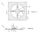
- FIG. 1Ais a top view of pointing device 10 .
- FIG. 1Bis a cross-sectional view of pointing device 10 through line 1 B— 1 B shown in FIG. 1A .
- FIG. 2is a top view of a pointing device 70 that utilizes a suspension system according to one embodiment of the present invention.
- FIGS. 3–5illustrate the construction of a puck, springs, and puck field of motion boundary according to one embodiment of the present invention at various stages in the fabrication process.
- FIGS. 1A–1Billustrate a pointing device 10 that utilizes a puck of the type discussed above to implement a pointing device.
- FIG. 1Ais a top view of pointing device 10 and FIG. 1B is a cross-sectional view of pointing device 10 through line 1 B— 1 B shown in FIG. 1A .
- Pointing device 10includes a puck 11 that moves over a surface 12 of a substrate 15 within a puck field of motion 19 in response to a lateral force being applied to puck 11 . The force is typically applied to puck 11 by a user's finger, thumb or multiple fingers.
- pointing device 10includes a sensing mechanism for determining the position of puck 11 on surface 12 .
- the meander springs shown at 13 that connect puck 11 to the periphery 14 of the puck field of motionreturn the puck to a predetermined location in the puck field of motion.
- the position of the puck in the puck field of motionmay be determined by a number of different methods. Since the method of determining the puck position is not relevant to the present discussion, the various position sensing mechanisms will not be discussed in detail here. For the purposes of the present discussion, it is sufficient to note that a number of these methods involve measuring the capacitance between one or more electrodes on the puck and electrodes on surface 12 .
- An exemplary puck electrodeis shown at 21 in FIG. 1B .
- meander springs shown at 13provide the required restoring force
- meander springshave several problems.
- the meander springs shown in FIGS. 1A–1Bprevent the puck from reaching all portions of the puck field of motion. This is particularly true if the puck motion is toward the attachment point of the spring on the periphery of the puck field of motion.
- a somewhat larger lateral areais needed to accommodate the unusable space on the surface that is required for the springs in their compressed state.
- the force required for moving the puckis different for different areas of the puck field of motion and different directions of motion.
- Common helical coiled springshave similar problems.
- the springshave a significant thickness, which increases the thickness of the pointing device.
- the device thicknesscan be a problem in many applications in which space is at a premium.
- Other solutions, such as elastic membranes, or radial segments of rubbersuffer from non-linearity of the force response and thereby exert excessive force on the user near the perimeter.
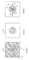
- FIG. 2is a top view of a pointing device 70 that utilizes a suspension system according to one embodiment of the present invention.
- Pointing device 70uses a spiral spring design that more nearly provides the ideal characteristics discussed above.
- Puck 75is attached to four spiral springs shown at 71 – 74 .
- Each spiral memberhas one end attached to puck 75 and the other end attached to the fixed portion of the pointing device at a point on the boundary 78 of the puck field of motion that is defined by the opening in plate 76 .
- a typical attachment pointis shown at 77 .
- the optimal springis a spiral that turns through approximately 270–360 degrees. That is, a spring connected to the top of the puck at 12 o'clock as shown at 79 ends between 9 o'clock and 12 o'clock on the boundary of the puck field of motion as shown at 77 . While this is the preferred spring configuration, other spring configurations can be utilized. If shorter springs are used, the puck tends to rotate as it moves to the extremities of the puck field of motion. Such rotations can interfere with the position sensing mechanism in some designs. Springs longer than 360 degrees consume more of the available space and result in softer restoring forces.
- the puck design shown in FIG. 2has a dead space adjacent to the boundary of the puck field of motion that is three times the width of a spring.
- Metal springs that are approximately 0.25 mm in widthperform adequately. Hence, an area that is less than 1 mm wide adjacent to the boundary of the puck field of motion is all that is wasted in such spiral spring based pointing devices.
- Plastic springs 0.75 mm wide and 1.5 mm thickare adequate for a puck that is 30 mm in diameter in a 60 mm diameter field of motion.
- k and k′are constants. While this curve is a good approximation for most of the spring's length, a curve that differs from this relationship at the two ends is advantageous.
- the two ends of the spiralare modified to make the ends nearly tangential [adjectival form] to the points at which the spring attaches to the puck and the boundary of the puck field of motion. This modification allows the puck to more easily reach the extremities of the puck field of motion.
- R, ⁇polar coordinate system
- other forms of arcuate springscan be utilized; although such springs do not provide all of the advantages of the spiral members discussed above.
- the above-described embodiments of the present inventionutilize four springs for restoring the puck to its resting position.
- other numbers of springscan be utilized.
- one springcould be used; however, the spring would need to provide the return force in two directions, and hence, would no longer be isotropic, and would be much stiffer than the springs described above.
- more springscan be used to provide additional electrical connections to the puck.
- the springs in the above-described embodimentsideally return the puck to a resting position that is in the center of the field of motion. Such embodiments maximize the amount of motion that can be accommodated from the resting position.
- the puckneed not be returned exactly to the same starting position each time it is released.
- the puckneed not return to a resting position that is exactly in the center of the puck field of motion. So long as the puck returns to a position that is near enough to the center of the puck field of motion to allow the puck to be moved from that position to a new position in some desired direction, the present invention will provide an improvement over the meander spring design discussed above.
- the puckincludes some form of oscillation damping to ensure that the puck will return to its resting position with as few oscillations as possible.
- One method for damping oscillationsis to assure that the puck remains pressed against the underlying surface as it returns to its resting position when released by the user. In this case, friction between the puck and underlying surface provides the damping force. This can be accomplished by mounting the springs such that the springs apply a downward force on the puck.
- the attachment point for the end of the spring on the puckcan be located at a greater distance from the underlying surface than the attachment point for the other end of the spring.
- the springscan be deformed so that each spring exerts a downward force in addition to the restoring forces described above.
- the present inventionis also simple and economical to fabricate.
- the puck and springscan be formed from a sheet of material of the type used for the springs by stamping or etching the sheet to generate the puck and springs attached to a border that provides the boundary of the puck field of motion.
- conventional photolithography techniquescan be used to etch a sheet of plastic to form a plastic puck and plastic springs attached to the edges of the sheet.
- FIGS. 3–5illustrate the construction of a puck, springs, and puck field of motion boundary according to one embodiment of the present invention at various stages in the fabrication process.
- the processstarts by protecting the area of a sheet of plastic that will become the puck 81 , springs 82 , and boundary 83 with a photoresist pattern as shown in FIG. 3 .
- the plasticis then etched to remove the unprotected portions of the plastic between the springs, and the photoresist removed to leave a single plastic structure 86 as shown in FIG. 4 .
- the electrodescan be deposited and patterned using conventional plating techniques or vacuum deposition such as sputtering. Exemplary electrodes are shown at 91 and 92 in FIG. 5 . If electrical connections to the electrodes are required, one or more of the springs can also be plated with electrical conductors that connect the electrodes to the periphery of the puck field of motion. For example, electrode 91 is connected to lead 94 by plated spring 93 . Similarly, electrode 92 is connected to lead 96 by plated spring 95 .
- the puck, springs and peripherycan also be molded from plastic in a single step using techniques well known in the art. Conductors can also be embedded during the molding process, in addition to the plating, or vacuum deposition techniques discussed above.
- the puck field of motioncan have other shapes.
- the puck field of motioncould be elliptical or rectangular.
- the optimal spring shapeswill be different than those described above, but will still generally be arcuate springs.
- the above-described embodiments of the present inventionhave utilized a puck as the moveable object.
- the present inventionmay be applied to other objects as well. Accordingly, the term “puck” as used herein includes any object that is to be returned to a fixed point in a field of motion.
Landscapes
- Engineering & Computer Science (AREA)
- General Engineering & Computer Science (AREA)
- Theoretical Computer Science (AREA)
- Human Computer Interaction (AREA)
- Physics & Mathematics (AREA)
- General Physics & Mathematics (AREA)
- Position Input By Displaying (AREA)
- Springs (AREA)
- Piezo-Electric Or Mechanical Vibrators, Or Delay Or Filter Circuits (AREA)
- Current-Collector Devices For Electrically Propelled Vehicles (AREA)
- Vehicle Body Suspensions (AREA)
- Fluid-Damping Devices (AREA)
Abstract
Description
Claims (7)
Priority Applications (8)
| Application Number | Priority Date | Filing Date | Title |
|---|---|---|---|
| US10/723,596US7158115B2 (en) | 2003-11-24 | 2003-11-24 | Spring system for re-centering a movable object |
| KR1020067010040AKR101083954B1 (en) | 2003-11-24 | 2004-11-10 | Spring system for recentering movable object |
| JP2006541252AJP4815354B2 (en) | 2003-11-24 | 2004-11-10 | Spring system for re-centering a movable object |
| EP04800951AEP1687702B1 (en) | 2003-11-24 | 2004-11-10 | Spring system for re-centering a moveable object |
| CNB2004800347331ACN100524177C (en) | 2003-11-24 | 2004-11-10 | Spring system for re-centering a moveable object |
| DE602004023416TDE602004023416D1 (en) | 2003-11-24 | 2004-11-10 | SPRING SYSTEM FOR RECENTING A MOVABLE OBJECT |
| PCT/US2004/037480WO2005055038A2 (en) | 2003-11-24 | 2004-11-10 | Spring system for re-centering a moveable object |
| AT04800951TATE444517T1 (en) | 2003-11-24 | 2004-11-10 | SPRING SYSTEM FOR RE-CENTERING A MOVING OBJECT |
Applications Claiming Priority (1)
| Application Number | Priority Date | Filing Date | Title |
|---|---|---|---|
| US10/723,596US7158115B2 (en) | 2003-11-24 | 2003-11-24 | Spring system for re-centering a movable object |
Publications (2)
| Publication Number | Publication Date |
|---|---|
| US20050110747A1 US20050110747A1 (en) | 2005-05-26 |
| US7158115B2true US7158115B2 (en) | 2007-01-02 |
Family
ID=34592317
Family Applications (1)
| Application Number | Title | Priority Date | Filing Date |
|---|---|---|---|
| US10/723,596Expired - Fee RelatedUS7158115B2 (en) | 2003-11-24 | 2003-11-24 | Spring system for re-centering a movable object |
Country Status (8)
| Country | Link |
|---|---|
| US (1) | US7158115B2 (en) |
| EP (1) | EP1687702B1 (en) |
| JP (1) | JP4815354B2 (en) |
| KR (1) | KR101083954B1 (en) |
| CN (1) | CN100524177C (en) |
| AT (1) | ATE444517T1 (en) |
| DE (1) | DE602004023416D1 (en) |
| WO (1) | WO2005055038A2 (en) |
Cited By (18)
| Publication number | Priority date | Publication date | Assignee | Title |
|---|---|---|---|---|
| US20050110754A1 (en)* | 2003-11-24 | 2005-05-26 | Jonah Harley | Modular assembly for a self-indexing computer pointing device |
| US20050110755A1 (en)* | 2003-11-24 | 2005-05-26 | Jonah Harley | Compact pointing device |
| US20060055667A1 (en)* | 2004-09-16 | 2006-03-16 | Farid Matta | Pointing device with extended travel |
| US20060117894A1 (en)* | 2004-10-20 | 2006-06-08 | Masaki Sawada | Neutral position returning mechanism and input device using the same |
| US20060158424A1 (en)* | 2005-01-19 | 2006-07-20 | Tong Xie | Optical slide pad |
| US20060158429A1 (en)* | 2005-01-14 | 2006-07-20 | Harley Jonah A | Pointing device including a moveable puck with mechanical detents |
| US20070139374A1 (en)* | 2005-12-19 | 2007-06-21 | Jonah Harley | Pointing device adapted for small handheld devices |
| US20070247446A1 (en)* | 2006-04-25 | 2007-10-25 | Timothy James Orsley | Linear positioning input device |
| US20080018596A1 (en)* | 2006-07-18 | 2008-01-24 | Jonah Harley | Capacitive sensing in displacement type pointing devices |
| US20080099322A1 (en)* | 2004-09-29 | 2008-05-01 | BSH Bosch und Siemens Hausgeräte GmbH | Capacitive Proximity and/or Touch-Sensitive Switch |
| US20080289942A1 (en)* | 2007-05-25 | 2008-11-27 | Shenzhen Futaihong Precision Industry Co., Ltd. | Keypad assembly and portable electronic device with same |
| US20090057124A1 (en)* | 2007-08-27 | 2009-03-05 | Timothy James Orsley | Control and Data Entry Apparatus |
| US20090058802A1 (en)* | 2007-08-27 | 2009-03-05 | Avago Technologies Ecbu Ip (Singapore) Pte. Ltd. | Input device |
| US20090135136A1 (en)* | 2007-11-23 | 2009-05-28 | Timothy James Orsley | Magnetic Re-Centering Mechanism for a Capacitive Input Device |
| US20090135157A1 (en)* | 2007-11-27 | 2009-05-28 | Avago Technologies Ecbu Ip (Singapore) Pte. Ltd. | Capacitive Sensing Input Device with Reduced Sensitivity to Humidity and Condensation |
| US7586480B2 (en) | 2005-02-28 | 2009-09-08 | Avago Technologies Ecbu Ip (Singapore) Pte. Ltd. | Hybrid pointing device |
| US20100045598A1 (en)* | 2008-08-20 | 2010-02-25 | Honeywell International Inc. | Apparatus for controlling the movement of an object on a plane |
| US20120086635A1 (en)* | 2009-03-11 | 2012-04-12 | Innochips Technology Co., Ltd | Pointing device and electronic device having the same |
Families Citing this family (10)
| Publication number | Priority date | Publication date | Assignee | Title |
|---|---|---|---|---|
| US7733327B2 (en)* | 2006-04-19 | 2010-06-08 | Avago Technologies Ecbu Ip (Singapore) Pte. Ltd. | Re-centering mechanism for an input device |
| US20080042974A1 (en)* | 2006-08-17 | 2008-02-21 | Sachs Todd S | System and method for determining cursor speed in a puck-based pointing device |
| US8188970B2 (en)* | 2006-08-17 | 2012-05-29 | Avago Technologies Ecbu Ip (Singapore) Pte. Ltd. | System and method for automatic re-calulation and monitoring of thresholds in a puck-based pointing device |
| US7800581B2 (en)* | 2006-09-15 | 2010-09-21 | Avago Technologies Ecbu Ip (Singapore) Pte. Ltd. | User input device with self-centering flat spring |
| US8115127B2 (en)* | 2007-08-30 | 2012-02-14 | Siemens Industry, Inc. | Extended drive plate deliberate action rotary handle |
| KR100931069B1 (en)* | 2008-02-15 | 2009-12-10 | 주식회사 이노칩테크놀로지 | Pointing device and electronic device having the same |
| TWI497352B (en)* | 2008-04-28 | 2015-08-21 | Innochips Technology Co Ltd | Electronic device and method for controlling program thereof |
| WO2011094877A1 (en)* | 2010-02-08 | 2011-08-11 | Optotune Ag | Input device with elastic membrane |
| WO2013052005A2 (en)* | 2011-10-07 | 2013-04-11 | Quek Joo Hai | A self-centering input device |
| TWI737525B (en)* | 2020-10-28 | 2021-08-21 | 緯創資通股份有限公司 | Screw nut and electronic device having the same |
Citations (11)
| Publication number | Priority date | Publication date | Assignee | Title |
|---|---|---|---|---|
| US4670743A (en)* | 1985-01-31 | 1987-06-02 | General Instrument Corporation | Keyboard cursor controller |
| US5065146A (en)* | 1987-06-18 | 1991-11-12 | International Business Machines Corporation | Manually-operated control device |
| US5086296A (en)* | 1987-12-02 | 1992-02-04 | U.S. Philips Corporation | Signal generating device |
| US5252952A (en) | 1990-10-26 | 1993-10-12 | The Cherry Corporation | Cursor device with zero-point resetting |
| US5504502A (en)* | 1990-09-18 | 1996-04-02 | Fujitsu Limited | Pointing control device for moving a cursor on a display on a computer |
| US5704037A (en)* | 1996-03-20 | 1997-12-30 | Chen; Mei Yun | Cursor positioning device for computer system |
| US5808603A (en)* | 1997-02-06 | 1998-09-15 | Chen; Mei Yun | Computer input device |
| US5956016A (en)* | 1996-03-19 | 1999-09-21 | Bayerische Motoren Werke Aktiengesellschaft | Operating device for menu-controlled functions of a vehicle |
| US6256012B1 (en)* | 1998-08-25 | 2001-07-03 | Varatouch Technology Incorporated | Uninterrupted curved disc pointing device |
| US6326948B1 (en)* | 1997-01-20 | 2001-12-04 | Sharp Kabushiki Kaisha | Input device |
| WO2003030092A1 (en) | 2001-09-04 | 2003-04-10 | Ziad Badarneh | Operating device for controlling functions in electronic equipment |
Family Cites Families (4)
| Publication number | Priority date | Publication date | Assignee | Title |
|---|---|---|---|---|
| GB9018200D0 (en) | 1990-08-18 | 1990-10-03 | Sherriff David R | Hand operated transducer for precise electronic control |
| JPH11134108A (en)* | 1997-10-28 | 1999-05-21 | Sharp Corp | Pointing input device |
| JP2003084916A (en)* | 2001-09-11 | 2003-03-20 | Alps Electric Co Ltd | Coordinate input device |
| JP4175007B2 (en)* | 2002-03-22 | 2008-11-05 | 松下電器産業株式会社 | Rotation operation type input device |
- 2003
- 2003-11-24USUS10/723,596patent/US7158115B2/ennot_activeExpired - Fee Related
- 2004
- 2004-11-10WOPCT/US2004/037480patent/WO2005055038A2/ennot_activeApplication Discontinuation
- 2004-11-10KRKR1020067010040Apatent/KR101083954B1/ennot_activeExpired - Fee Related
- 2004-11-10DEDE602004023416Tpatent/DE602004023416D1/ennot_activeExpired - Lifetime
- 2004-11-10ATAT04800951Tpatent/ATE444517T1/ennot_activeIP Right Cessation
- 2004-11-10CNCNB2004800347331Apatent/CN100524177C/ennot_activeExpired - Fee Related
- 2004-11-10EPEP04800951Apatent/EP1687702B1/ennot_activeExpired - Lifetime
- 2004-11-10JPJP2006541252Apatent/JP4815354B2/ennot_activeExpired - Fee Related
Patent Citations (11)
| Publication number | Priority date | Publication date | Assignee | Title |
|---|---|---|---|---|
| US4670743A (en)* | 1985-01-31 | 1987-06-02 | General Instrument Corporation | Keyboard cursor controller |
| US5065146A (en)* | 1987-06-18 | 1991-11-12 | International Business Machines Corporation | Manually-operated control device |
| US5086296A (en)* | 1987-12-02 | 1992-02-04 | U.S. Philips Corporation | Signal generating device |
| US5504502A (en)* | 1990-09-18 | 1996-04-02 | Fujitsu Limited | Pointing control device for moving a cursor on a display on a computer |
| US5252952A (en) | 1990-10-26 | 1993-10-12 | The Cherry Corporation | Cursor device with zero-point resetting |
| US5956016A (en)* | 1996-03-19 | 1999-09-21 | Bayerische Motoren Werke Aktiengesellschaft | Operating device for menu-controlled functions of a vehicle |
| US5704037A (en)* | 1996-03-20 | 1997-12-30 | Chen; Mei Yun | Cursor positioning device for computer system |
| US6326948B1 (en)* | 1997-01-20 | 2001-12-04 | Sharp Kabushiki Kaisha | Input device |
| US5808603A (en)* | 1997-02-06 | 1998-09-15 | Chen; Mei Yun | Computer input device |
| US6256012B1 (en)* | 1998-08-25 | 2001-07-03 | Varatouch Technology Incorporated | Uninterrupted curved disc pointing device |
| WO2003030092A1 (en) | 2001-09-04 | 2003-04-10 | Ziad Badarneh | Operating device for controlling functions in electronic equipment |
Cited By (28)
| Publication number | Priority date | Publication date | Assignee | Title |
|---|---|---|---|---|
| US20050110754A1 (en)* | 2003-11-24 | 2005-05-26 | Jonah Harley | Modular assembly for a self-indexing computer pointing device |
| US20050110755A1 (en)* | 2003-11-24 | 2005-05-26 | Jonah Harley | Compact pointing device |
| US7570247B2 (en) | 2003-11-24 | 2009-08-04 | Avago Technologies Ecbu Ip (Singapore) Pte. Ltd. | Modular assembly for a self-indexing computer pointing device |
| US7429976B2 (en) | 2003-11-24 | 2008-09-30 | Avago Technologies Ecbu Ip (Singapore) Pte. Ltd. | Compact pointing device |
| US20060055667A1 (en)* | 2004-09-16 | 2006-03-16 | Farid Matta | Pointing device with extended travel |
| US7679600B2 (en)* | 2004-09-16 | 2010-03-16 | Avago Technologies Ecbu Ip (Singapore) Pte. Ltd. | Pointing device with extended travel |
| US20080099322A1 (en)* | 2004-09-29 | 2008-05-01 | BSH Bosch und Siemens Hausgeräte GmbH | Capacitive Proximity and/or Touch-Sensitive Switch |
| US20060117894A1 (en)* | 2004-10-20 | 2006-06-08 | Masaki Sawada | Neutral position returning mechanism and input device using the same |
| US7439461B2 (en)* | 2004-10-20 | 2008-10-21 | Matsushita Electric Industrial Co., Ltd. | Neutral position returning mechanism and input device using the same |
| US7978173B2 (en) | 2005-01-14 | 2011-07-12 | Avago Technologies Ecbu Ip (Singapore) Pte. Ltd. | Pointing device including a moveable puck with mechanical detents |
| US20060158429A1 (en)* | 2005-01-14 | 2006-07-20 | Harley Jonah A | Pointing device including a moveable puck with mechanical detents |
| US20060158424A1 (en)* | 2005-01-19 | 2006-07-20 | Tong Xie | Optical slide pad |
| US7586480B2 (en) | 2005-02-28 | 2009-09-08 | Avago Technologies Ecbu Ip (Singapore) Pte. Ltd. | Hybrid pointing device |
| US20070139374A1 (en)* | 2005-12-19 | 2007-06-21 | Jonah Harley | Pointing device adapted for small handheld devices |
| US7701440B2 (en) | 2005-12-19 | 2010-04-20 | Avago Technologies Ecbu Ip (Singapore) Pte. Ltd. | Pointing device adapted for small handheld devices having two display modes |
| US20070247446A1 (en)* | 2006-04-25 | 2007-10-25 | Timothy James Orsley | Linear positioning input device |
| US7889176B2 (en) | 2006-07-18 | 2011-02-15 | Avago Technologies General Ip (Singapore) Pte. Ltd. | Capacitive sensing in displacement type pointing devices |
| US20080018596A1 (en)* | 2006-07-18 | 2008-01-24 | Jonah Harley | Capacitive sensing in displacement type pointing devices |
| US7459646B1 (en)* | 2007-05-25 | 2008-12-02 | Shenzhen Futaihong Precision Industry Co., Ltd. | Keypad assembly and portable electronic device with same |
| US20080289942A1 (en)* | 2007-05-25 | 2008-11-27 | Shenzhen Futaihong Precision Industry Co., Ltd. | Keypad assembly and portable electronic device with same |
| US20090058802A1 (en)* | 2007-08-27 | 2009-03-05 | Avago Technologies Ecbu Ip (Singapore) Pte. Ltd. | Input device |
| US20090057124A1 (en)* | 2007-08-27 | 2009-03-05 | Timothy James Orsley | Control and Data Entry Apparatus |
| US8232963B2 (en) | 2007-08-27 | 2012-07-31 | Avago Technologies Ecbu Ip (Singapore) Pte. Ltd. | Control and data entry apparatus |
| US20090135136A1 (en)* | 2007-11-23 | 2009-05-28 | Timothy James Orsley | Magnetic Re-Centering Mechanism for a Capacitive Input Device |
| US7978175B2 (en) | 2007-11-23 | 2011-07-12 | Avago Technologies Ecbu Ip (Singapore) Pte. Ltd. | Magnetic re-centering mechanism for a capacitive input device |
| US20090135157A1 (en)* | 2007-11-27 | 2009-05-28 | Avago Technologies Ecbu Ip (Singapore) Pte. Ltd. | Capacitive Sensing Input Device with Reduced Sensitivity to Humidity and Condensation |
| US20100045598A1 (en)* | 2008-08-20 | 2010-02-25 | Honeywell International Inc. | Apparatus for controlling the movement of an object on a plane |
| US20120086635A1 (en)* | 2009-03-11 | 2012-04-12 | Innochips Technology Co., Ltd | Pointing device and electronic device having the same |
Also Published As
| Publication number | Publication date |
|---|---|
| WO2005055038A2 (en) | 2005-06-16 |
| KR101083954B1 (en) | 2011-11-16 |
| CN100524177C (en) | 2009-08-05 |
| DE602004023416D1 (en) | 2009-11-12 |
| EP1687702A2 (en) | 2006-08-09 |
| EP1687702B1 (en) | 2009-09-30 |
| KR20060117956A (en) | 2006-11-17 |
| CN1898633A (en) | 2007-01-17 |
| ATE444517T1 (en) | 2009-10-15 |
| JP2007513414A (en) | 2007-05-24 |
| WO2005055038A3 (en) | 2005-09-15 |
| US20050110747A1 (en) | 2005-05-26 |
| JP4815354B2 (en) | 2011-11-16 |
Similar Documents
| Publication | Publication Date | Title |
|---|---|---|
| US7158115B2 (en) | Spring system for re-centering a movable object | |
| JP4909080B2 (en) | Small pointing device | |
| EP0759199B1 (en) | Force-sensing pointing device | |
| US6256012B1 (en) | Uninterrupted curved disc pointing device | |
| JP4429477B2 (en) | Force detection device and operation amount detection device | |
| EP1843373B1 (en) | Direction detection switch | |
| EP3692433B1 (en) | Piezo haptic feedback device with integrated support | |
| US4978818A (en) | Key for a circuit board | |
| JP4226643B2 (en) | Straining body, capacitive force sensor and capacitive acceleration sensor | |
| TWI377489B (en) | Pointing device with extended travel | |
| US6545238B2 (en) | Key device with a scissors mechanism | |
| US11728109B2 (en) | Key structure | |
| US10838521B2 (en) | Touch stylus | |
| CN118456480B (en) | Touch manipulator and control method thereof | |
| JPH0326556Y2 (en) | ||
| KR20060004868A (en) | Manufacturing method of touch panel for reducing defective rate by handling | |
| JPH07181089A (en) | Capacitive sensor | |
| JPH07226128A (en) | Operation button device |
Legal Events
| Date | Code | Title | Description |
|---|---|---|---|
| AS | Assignment | Owner name:AGILENT TECHNOLOGIES, INC., COLORADO Free format text:ASSIGNMENT OF ASSIGNORS INTEREST;ASSIGNORS:HARLEY, JONAH;HOEN, STORRS;REEL/FRAME:014563/0591 Effective date:20031119 | |
| AS | Assignment | Owner name:AVAGO TECHNOLOGIES GENERAL IP PTE. LTD.,SINGAPORE Free format text:ASSIGNMENT OF ASSIGNORS INTEREST;ASSIGNOR:AGILENT TECHNOLOGIES, INC.;REEL/FRAME:017206/0666 Effective date:20051201 Owner name:AVAGO TECHNOLOGIES GENERAL IP PTE. LTD., SINGAPORE Free format text:ASSIGNMENT OF ASSIGNORS INTEREST;ASSIGNOR:AGILENT TECHNOLOGIES, INC.;REEL/FRAME:017206/0666 Effective date:20051201 | |
| AS | Assignment | Owner name:AVAGO TECHNOLOGIES ECBU IP (SINGAPORE) PTE. LTD., SINGAPORE Free format text:ASSIGNMENT OF ASSIGNORS INTEREST;ASSIGNOR:AVAGO TECHNOLOGIES GENERAL IP (SINGAPORE) PTE. LTD.;REEL/FRAME:017675/0518 Effective date:20060127 Owner name:AVAGO TECHNOLOGIES ECBU IP (SINGAPORE) PTE. LTD.,S Free format text:ASSIGNMENT OF ASSIGNORS INTEREST;ASSIGNOR:AVAGO TECHNOLOGIES GENERAL IP (SINGAPORE) PTE. LTD.;REEL/FRAME:017675/0518 Effective date:20060127 Owner name:AVAGO TECHNOLOGIES ECBU IP (SINGAPORE) PTE. LTD., Free format text:ASSIGNMENT OF ASSIGNORS INTEREST;ASSIGNOR:AVAGO TECHNOLOGIES GENERAL IP (SINGAPORE) PTE. LTD.;REEL/FRAME:017675/0518 Effective date:20060127 | |
| FPAY | Fee payment | Year of fee payment:4 | |
| AS | Assignment | Owner name:AVAGO TECHNOLOGIES GENERAL IP (SINGAPORE) PTE. LTD Free format text:MERGER;ASSIGNOR:AVAGO TECHNOLOGIES ECBU IP (SINGAPORE) PTE. LTD.;REEL/FRAME:030251/0018 Effective date:20121030 | |
| AS | Assignment | Owner name:AVAGO TECHNOLOGIES GENERAL IP (SINGAPORE) PTE. LTD Free format text:MERGER;ASSIGNOR:AVAGO TECHNOLOGIES ECBU IP (SINGAPORE) PTE. LTD.;REEL/FRAME:030369/0528 Effective date:20121030 | |
| REMI | Maintenance fee reminder mailed | ||
| LAPS | Lapse for failure to pay maintenance fees | ||
| STCH | Information on status: patent discontinuation | Free format text:PATENT EXPIRED DUE TO NONPAYMENT OF MAINTENANCE FEES UNDER 37 CFR 1.362 | |
| FP | Lapsed due to failure to pay maintenance fee | Effective date:20150102 | |
| AS | Assignment | Owner name:AVAGO TECHNOLOGIES GENERAL IP (SINGAPORE) PTE. LTD Free format text:CORRECTIVE ASSIGNMENT TO CORRECT THE ASSIGNEE NAME PREVIOUSLY RECORDED AT REEL: 017206 FRAME: 0666. ASSIGNOR(S) HEREBY CONFIRMS THE ASSIGNMENT;ASSIGNOR:AGILENT TECHNOLOGIES, INC.;REEL/FRAME:038632/0662 Effective date:20051201 |