US7156770B2 - Continuously variable transmission - Google Patents
Continuously variable transmissionDownload PDFInfo
- Publication number
- US7156770B2 US7156770B2US11/006,212US621204AUS7156770B2US 7156770 B2US7156770 B2US 7156770B2US 621204 AUS621204 AUS 621204AUS 7156770 B2US7156770 B2US 7156770B2
- Authority
- US
- United States
- Prior art keywords
- spindle
- motorcycle
- transmission
- shaft
- platform
- Prior art date
- Legal status (The legal status is an assumption and is not a legal conclusion. Google has not performed a legal analysis and makes no representation as to the accuracy of the status listed.)
- Expired - Fee Related, expires
Links
Images


Classifications
- B—PERFORMING OPERATIONS; TRANSPORTING
- B62—LAND VEHICLES FOR TRAVELLING OTHERWISE THAN ON RAILS
- B62M—RIDER PROPULSION OF WHEELED VEHICLES OR SLEDGES; POWERED PROPULSION OF SLEDGES OR SINGLE-TRACK CYCLES; TRANSMISSIONS SPECIALLY ADAPTED FOR SUCH VEHICLES
- B62M11/00—Transmissions characterised by the use of interengaging toothed wheels or frictionally-engaging wheels
- F—MECHANICAL ENGINEERING; LIGHTING; HEATING; WEAPONS; BLASTING
- F16—ENGINEERING ELEMENTS AND UNITS; GENERAL MEASURES FOR PRODUCING AND MAINTAINING EFFECTIVE FUNCTIONING OF MACHINES OR INSTALLATIONS; THERMAL INSULATION IN GENERAL
- F16H—GEARING
- F16H15/00—Gearings for conveying rotary motion with variable gear ratio, or for reversing rotary motion, by friction between rotary members
- F16H15/02—Gearings for conveying rotary motion with variable gear ratio, or for reversing rotary motion, by friction between rotary members without members having orbital motion
- F16H15/04—Gearings providing a continuous range of gear ratios
- F16H15/06—Gearings providing a continuous range of gear ratios in which a member A of uniform effective diameter mounted on a shaft may co-operate with different parts of a member B
- F16H15/26—Gearings providing a continuous range of gear ratios in which a member A of uniform effective diameter mounted on a shaft may co-operate with different parts of a member B in which the member B has a spherical friction surface centered on its axis of revolution
- F16H15/28—Gearings providing a continuous range of gear ratios in which a member A of uniform effective diameter mounted on a shaft may co-operate with different parts of a member B in which the member B has a spherical friction surface centered on its axis of revolution with external friction surface
- F—MECHANICAL ENGINEERING; LIGHTING; HEATING; WEAPONS; BLASTING
- F16—ENGINEERING ELEMENTS AND UNITS; GENERAL MEASURES FOR PRODUCING AND MAINTAINING EFFECTIVE FUNCTIONING OF MACHINES OR INSTALLATIONS; THERMAL INSULATION IN GENERAL
- F16H—GEARING
- F16H61/00—Control functions within control units of change-speed- or reversing-gearings for conveying rotary motion ; Control of exclusively fluid gearing, friction gearing, gearings with endless flexible members or other particular types of gearing
- F16H61/66—Control functions within control units of change-speed- or reversing-gearings for conveying rotary motion ; Control of exclusively fluid gearing, friction gearing, gearings with endless flexible members or other particular types of gearing specially adapted for continuously variable gearings
- F16H61/664—Friction gearings
Definitions
- the field of the inventionrelates to transmissions. More particularly the invention relates to continuously variable transmissions.
- Yet another limitation of this designis that it requires the use of two half axles, one on each side of the rollers, to provide a gap in the middle of the two half axles. The gap is necessary because the rollers are shifted with rotating motion instead of sliding linear motion.
- the use of two axlesis not desirable and requires a complex fastening system to prevent the axles from bending when the transmission is accidentally bumped, is as often the case when a transmission is employed in a vehicle.
- Yet another limitation of this designis that it does not provide for an automatic transmission.
- the present inventionincludes a transmission for use in rotationally or linearly powered machines and vehicles.
- the present transmissionmay be used in machines such as drill presses, turbines, and food processing equipment, and vehicles such as automobiles, motorcycles, and bicycles.
- the transmissionmay, for example, be driven by a power transfer mechanism such as a sprocket, gear, pulley or lever, optionally driving a one way clutch attached at one end of the main shaft.
- the transmissioncomprises a rotatable driving member, three or more power adjusters, wherein each of the power adjusters respectively rotates about an axis of rotation that is centrally located within each of the power adjusters, a support member providing a support surface that is in frictional contact with each of the power adjusters, wherein the support member rotates about an axis that is centrally located within the support member, at least one platform for actuating axial movement of the support member and for actuating a shift in the axis of rotation of the power adjusters, wherein the platform provides a convex surface, at least one stationary support that is non-rotatable about the axis of rotation that is defined by the support member, wherein the at least one stationary support provides a concave surface, and a plurality of spindle supports, wherein each of the spindle supports are slidingly engaged with the convex surface of the platform and the concave surface of the stationary support, and wherein each of the spindle supports adjusts the axes of rotation
- the transmissioncomprises a rotatable driving member; three or more power adjusters, wherein each of the power adjusters respectively rotates about an axis of rotation that is respectively central to the power adjusters, a support member providing a support surface that is in frictional contact with each of the power adjusters, a rotatable driving member for rotating each of the power adjusters, a bearing disc having a plurality of inclined ramps for actuating the rotation of the driving member, a coiled spring for biasing the rotatable driving member against the power adjusters, at least one lock pawl ratchet, wherein the lock pawl ratchet is rigidly attached to the rotatable driving member, wherein the at least one lock pawl is operably attached to the coiled spring, and at least one lock pawl for locking the lock pawl ratchet in response to the rotatable driving member becoming disengaged from the power adjusters.
- the transmissioncomprises a rotatable driving member, three or more power adjusters, wherein each of the power adjusters respectively rotates about an axis that is respectively central to each of the power adjusters, a support member providing a support surface that is in frictional contact with each of the power adjusters, wherein the support member rotates about an axis that is centrally located within the support member, a bearing disc having a plurality of inclined ramps for actuating the rotation of the driving member, a screw that is coaxially and rigidly attached to the rotatable driving member or the bearing disc, and a nut that, if the screw is attached to the rotatable driving member, is coaxially and rigidly attached to the bearing disc, or if the screw is rigidly attached to the bearing disc, coaxially and rigidly attached to the rotatable driving member, wherein the inclined ramps of the bearing disc have a higher lead than the screw.
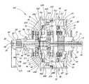
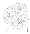
- FIG. 1is a cutaway side view of the transmission of the present invention.
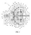
- FIG. 2is a partial perspective view of the transmission of FIG. 1 .
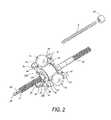
- FIG. 3is a perspective view of two stationary supports of the transmission of FIG. 1 .
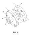
- FIG. 4is a partial end, cross-sectional view of the transmission of FIG. 1 .
- FIG. 5is a perspective view of a drive disc, bearing cage, screw, and ramp bearings of the transmission of FIG. 1 .
- FIG. 6is a perspective view of a ratchet and pawl subsystem of the transmission of FIG. 1 that is used to engage and disengage the transmission.
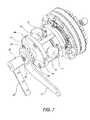
- FIG. 7is partial perspective view of the transmission of FIG. 1 , wherein, among other things, a rotatable drive disc has been removed.
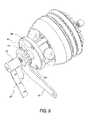
- FIG. 8is a partial perspective view of the transmission of FIG. 1 , wherein, among other things, the hub shell has been removed.
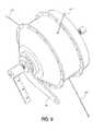
- FIG. 9is a partial perspective view of the transmission of FIG. 1 , wherein the shifting is done automatically.
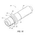
- FIG. 10is a perspective view of the shifting handlegrip that is mechanically coupled to the transmission of FIG. 1 .
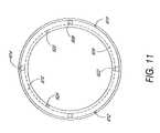
- FIG. 11is an end view of a thrust bearing, of the transmission shown in FIG. 1 , which is used for automatic shifting of the transmission.
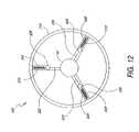
- FIG. 12is an end view of the weight design of the transmission shown in FIG. 1 .
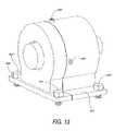
- FIG. 13is a perspective view of an alternate embodiment of the transmission bolted to a flat surface.
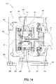
- FIG. 14is a cutaway side view of the transmission shown in FIG. 13 .
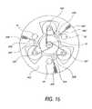
- FIG. 15is a schematic end view of the transmission in FIG. 1 showing the cable routing across a spacer extension of the automatic portion of the transmission.
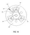
- FIG. 16is a schematic end view of the cable routing of the transmission shown in FIG. 13 .
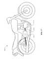
- FIG. 17is a schematic diagram of a motorcycle utilizing the continuously variable transmission of FIG. 1 .
- the present inventionincludes a continuously variable transmission that may be employed in connection with any type of machine that is in need of a transmission.
- the transmissionmay be used in (i) a motorized vehicle such as an automobile, motorcycle, or watercraft, (ii) a non-motorized vehicle such as a bicycle, tricycle, scooter, exercise equipment or (iii) industrial equipment, such as a drill press, power generating equipment, or textile mill.
- a continuously variable transmission 100is disclosed.
- the transmission 100is shrouded in a hub shell 40 covered by a hub cap 67 .
- At the heart of the transmission 100are three or more power adjusters 1 a , 1 b , 1 c which are spherical in shape and are circumferentially spaced equally around the centerline or axis of rotation of the transmission 100 .
- spindles 3 a , 3 b , 3 care inserted through the center of the power adjusters 1 a , 1 b , 1 c to define an axis of rotation for the power adjusters 1 a , 1 b , 1 c .
- FIG. 1In FIG.
- spindle supports 2 a–fare attached perpendicular to and at the exposed ends of the spindles 3 a , 3 b , 3 c .
- each of the spindles supportshave a bore to receive one end of one of the spindles 3 a , 3 b , 3 c .
- the spindles 3 a , 3 b , 3 calso have spindle rollers 4 a–f coaxially and slidingly positioned over the exposed ends of the spindles 3 a , 3 b , 3 c outside of the spindle supports 2 a–f.
- each spindle roller 4 a–ffollows in a groove 6 a–f cut into a stationary support 5 a , 5 b .
- the stationary supports 5 a , 5 bare generally in the form of parallel discs with an axis of rotation along the centerline of the transmission 100 .
- the grooves 6 a–fextend from the outer circumference of the stationary supports 5 a , 5 b towards the centerline of the transmission 100 .
- each pair of spindle rollers 4 a–flocated on a single spindle 3 a , 3 b , 3 c , moves in opposite directions along their corresponding grooves 6 a–f.
- a centerline hole 7 a , 7 b in the stationary supports 5 a , 5 ballows the insertion of a hollow shaft 10 through both stationary supports 5 a , 5 b .
- one or more of the stationary support holes 7 a , 7 bmay have a non-cylindrical shape 14 , which fits over a corresponding non-cylindrical shape 15 along the hollow shaft 10 to prevent any relative rotation between the stationary supports 5 a , 5 b and the hollow shaft 10 .
- additional structuremay be used to minimize any relative rotational movement or flexing of the stationary supports 5 a , 5 b .
- This type of movement by the stationary supports 5 a , 5 bmay cause binding of the spindle rollers 4 a–f as they move along the grooves 6 a–f.
- the additional structuremay take the form of spacers 8 a , 8 b , 8 c attached between the stationary supports 5 a , 5 b .
- the spacers 8 a , 8 b , 8 cadd rigidity between the stationary supports 5 a , 5 b and, in one embodiment, are located near the outer circumference of the stationary supports 5 a , 5 b .
- the stationary supports 5 a , 5 bare connected to the spacers 8 a , 8 b , 8 c by bolts or other fastener devices 45 a–f inserted through holes 46 a–f in the stationary supports 5 a , 5 b.
- the stationary support 5 ais fixedly attached to a stationary support sleeve 42 , which coaxially encloses the hollow shaft 10 and extends through the wall of the hub shell 40 .
- the end of the stationary support sleeve 42 that extends through the hub shell 40attaches to the frame support and preferentially has a non-cylindrical shape to enhance subsequent attachment of a torque lever 43 .
- the torque lever 43is placed over the non-cylindrical shaped end of the stationary support sleeve 42 , and is held in place by a torque nut 44 .
- the torque lever 43 at its other endis rigidly attached to a strong, non-moving part, such as a frame (not shown).
- a stationary support bearing 48supports the hub shell 40 and permits the hub shell 40 to rotate relative to the stationary support sleeve 42 .
- shiftingis manually activated by axially sliding a rod 11 positioned in the hollow shaft 10 .
- One or more pins 12are inserted through one or more transverse holes in the rod 11 and further extend through one or more longitudinal slots 16 (not shown) in the hollow shaft 10 .
- the slots 16 in the hollow shaft 10allow for axial movement of the pin 12 and rod 11 assembly in the hollow shaft 10 .
- the ends of the transverse pins 12extend into and couple with a coaxial sleeve 19 .
- the sleeve 19is fixedly attached at each end to a substantially planar platform 13 a , 13 b forming a trough around the circumference of the sleeve 19 .
- the planar platforms 13 a , 13 beach contact and push multiple wheels 21 a–f .
- the wheels 21 a–ffit into slots in the spindle supports 2 a–f and are held in place by wheel axles 22 a–f .
- the wheel axles 22 a–fare supported at their ends by the spindle supports 2 a–f and allow rotational movement of the wheels 21 a–f.
- the substantially planar platforms 13 a , 13 btransition into a convex surface at their outer perimeter (farthest from the hollow shaft 10 ). This region allows slack to be taken up when the spindle supports 2 a–f and power adjusters 1 a , 1 b , 1 c are tilted as the transmission 100 is shifted.
- a cylindrical support member 18is located in the trough formed between the planar platforms 13 a , 13 b and sleeve 19 and thus moves in concert with the planar platforms 13 a , 13 b and sleeve 19 .
- the support member 18rides on contact bearings 17 a , 17 b located at the intersection of the planar platforms 13 a , 13 b and sleeve 19 to allow the support member 18 to freely rotate about the axis of the transmission 100 .
- the bearings 17 a , 17 b , support member 18 , and sleeve 19all slide axially with the planar platforms 13 a , 13 b when the transmission 100 is shifted.
- stationary support rollers 30 a–lare attached in pairs to each spindle leg 2 a–f through a roller pin 31 a–f and held in place by roller clips 32 a–l .
- the roller pins 31 a–fallow the stationary support rollers 30 a–l to rotate freely about the roller pins 31 a–f .
- the stationary support rollers 30 a–lroll on a concave radius in the stationary support 5 a , 5 b along a substantially parallel path with the grooves 6 a–f .
- the stationary support rollers 30 a–ldo not allow the ends of the spindles 3 a , 3 b , 3 c nor the spindle rollers 4 a–f to contact the bottom surface of the grooves 6 a–f , to maintain the position of the spindles 3 a , 3 b , 3 c , and to minimize any frictional losses.
- FIG. 4shows the stationary support rollers 30 a–l , the roller pins, 31 a–f , and roller clips 32 a–l , as seen through the stationary support 5 a , for ease of viewing.
- the stationary support rollers 30 a–l , the roller pins, 31 a–f , and roller clips 32 a–lare not numbered in FIG. 1 .
- a concave drive disc 34located adjacent to the stationary support 5 b , partially encapsulates but does not contact the stationary support 5 b .
- the drive disc 34is rigidly attached through its center to a screw 35 .
- the screw 35is coaxial to and forms a sleeve around the hollow shaft 10 adjacent to the stationary support 5 b and faces a driving member 69 .
- the drive disc 34is rotatively coupled to the power adjusters 1 a , 1 b , 1 c along a circumferential bearing surface on the lip of the drive disc 34 .
- a nut 37is threaded over the screw 35 and is rigidly attached around its circumference to a bearing disc 60 .
- One face of the nut 37is further attached to the driving member 69 .
- a plurality of ramps 61which face the drive disc 34 .
- the ramp bearings 62contact both the ramps 61 and the drive disc 34 .
- a spring 65is attached at one end to the bearing cage 63 and at its other end to the drive disc 34 , or the bearing disc 60 in an alternate embodiment, to bias the ramp bearings 62 up the ramps 61 .
- the bearing disc 60on the side opposite the ramps 61 and at approximately the same circumference contacts a hub cap bearing 66 .
- the hub cap bearing 66contacts both the hub cap 67 and the bearing disc 60 to allow their relative motion.
- the hub cap 67is threaded or pressed into the hub shell 40 and secured with an internal ring 68 .
- a sprocket or pulley 38is rigidly attached to the rotating driving member 69 and is held in place externally by a cone bearing 70 secured by a cone nut 71 and internally by a driver bearing 72 which contacts both the driving member 69 and the hub cap 67 .
- an input rotation from the sprocket or pulley 38which is fixedly attached to the driver 69 , rotates the bearing disc 60 and the plurality of ramps 61 causing the ramp bearings 62 to roll up the ramps 61 and press the drive disc 34 against the power adjusters 1 a , 1 b , 1 c .
- the nut 37which has a smaller lead than the ramps 61 , rotates to cause the screw 35 and nut 37 to bind. This feature imparts rotation of the drive disc 34 against the power adjusters 1 a , 1 b , 1 c .
- the power adjusters 1 a , 1 b , 1 cwhen rotating, contact and rotate the hub shell 40 .
- the sprocket or pulley 38stops rotating but the hub shell 40 and the power adjusters 1 a , 1 b , 1 c , continue to rotate. This causes the drive disc 34 to rotate so that the screw 35 winds into the nut 37 until the drive disc 34 no longer contacts the power adjusters 1 a , 1 b , 1 c.
- a coiled spring 80coaxial with the transmission 100 , is located between and attached by pins or other fasteners (not shown) to both the bearing disc 60 and drive disc 34 at the ends of the coiled spring 80 .
- the coiled spring 80ensures contact between the power adjusters 1 a , 1 b , 1 c and the drive disc 34 .
- a pawl carrier 83fits in the coiled spring 80 with its middle coil attached to the pawl carrier 83 by a pin or standard fastener (not shown).
- the pawl carrier 83is attached to the middle coil of the coiled spring 80 , it rotates at half the speed of the drive disc 34 when the bearing disc 60 is not rotating.
- Thisallows one or more lock pawls 81 a , 81 b , 81 c , which are attached to the pawl carrier 83 by one or more pins 84 a , 84 b , 84 c , to engage a drive disc ratchet 82 , which is coaxial with and rigidly attached to the drive disc 34 .
- the one or more lock pawls 84 a , 84 b , 84 care preferably spaced asymmetrically around the drive disc ratchet 82 .
- the transmission 100is in neutral and the ease of shifting is increased.
- the transmission 100can also be shifted while in operation.
- one or more release pawls 85 a , 85 b , 85 ceach attached to one of the lock pawls 81 a , 81 b , 81 c by a pawl pin 88 a , 88 b , 88 c , make contact with an opposing bearing disc ratchet 87 .
- the bearing disc ratchet 87is coaxial with and rigidly attached to the bearing disc 60 .
- the bearing disc ratchet 87actuates the release pawls 85 a , 85 b , 85 c because the release pawls 85 a , 85 b , 85 c are connected to the pawl carrier 83 via the lock pawls 81 a , 81 b , 81 c .
- the release pawls 85 a , 85 b , 85 crotate at half the speed of the bearing disc 60 , since the drive disc 34 is not rotating, and disengage the lock pawls 81 a , 81 b , 81 c from the drive disc ratchet 82 allowing the coiled spring 80 to wind the drive disc 34 against the power adjusters 1 a , 1 b , 1 c .
- One or more pawl tensioners(not shown), one for each release pawl 85 a , 85 b , 85 c , ensures that the lock pawls 81 a , 81 b , 81 c are pressed against the drive disc ratchet 82 and that the release pawls 85 a , 85 b , 85 c are pressed against the bearing disc ratchet 87 .
- the pawl tensionersare attached at one end to the pawl carrier 83 and make contact at the other end to the release pawls 85 a , 85 b , 85 c .
- An assembly hole 93(not shown) through the hub cap 67 , the bearing disc 60 , and the drive disc 34 , allows an assembly pin (not shown) to be inserted into the loaded coiled spring 80 during assembly of the transmission 100 .
- the assembly pinprevents the coiled spring 80 from losing its tension and is removed after transmission 100 assembly is complete.
- automatic shifting of the transmission 100is accomplished by means of spindle cables 602 , 604 , 606 which are attached at one end to a non-moving component of the transmission 100 , such as the hollow shaft 10 or the stationary support 5 a .
- the spindle cables 602 , 604 , 606then travel around spindle pulleys 630 , 632 , 634 , which are coaxially positioned over the spindles 3 a , 3 b , 3 c .
- the spindle cables 602 , 604 , 606further travel around spacer pulleys 636 , 638 , 640 , 644 , 646 , 648 which are attached to a spacer extension 642 which may be rigidly attached to the spacers 8 a , 8 b , 8 c .
- the other ends of the spindle cables 602 , 604 , 606are attached to a plurality of holes 620 , 622 , 624 in a non-rotating annular bearing race 816 .
- a plurality of weight cables 532 , 534 , 536are attached at one end to a plurality of holes 610 , 612 , 614 in a rotating annular bearing race 806 .
- An annular bearing 808positioned between the rotating annular bearing race 806 and the non-rotating annular bearing race 816 , allows their relative movement.
- the transmission 100is shown with the cable routing for automatic shifting.
- the weight cables 532 , 534 , 536then travel around the hub shell pulleys 654 , 656 , 658 , through holes in the hub shell 40 , and into hollow spokes 504 , 506 , 508 (best seen in FIG. 12 ) where they attach to weights 526 , 528 , 530 .
- the weights 526 , 528 , 530are attached to and receive support from weight assisters 516 , 518 , 520 which attach to a wheel 514 or other rotating object at there opposite end.
- the weights 526 , 528 , 530are pulled radially away from the hub shell 40 , pulling the rotating annular bearing race 806 and the non-rotating annular bearing race 816 axially toward the hub cap 67 .
- the non-rotating annular bearing race 816pulls the spindle cables 602 , 604 , 606 , which pulls the spindle pulleys 630 , 632 , 634 closer to the hollow shaft 10 and results in the shifting of the transmission 100 into a higher gear.
- multiple tension membersmay be attached to the spindles 3 a , 3 b , 3 c opposite the spindle pulleys 630 , 632 , 634 .
- a rotatable shifter 50has internal threads that thread onto external threads of a shifter screw 52 which is attached over the hollow shaft 10 .
- the shifter 50has a cap 53 with a hole that fits over the rod 11 that is inserted into the hollow shaft 10 .
- the rod 11is threaded where it protrudes from the hollow shaft 10 so that nuts 54 , 55 may be threaded onto the rod 11 .
- the nuts 54 , 55are positioned on both sides of the cap 53 .
- a shifter lever 56is rigidly attached to the shifter 50 and provides a moment arm for the rod 11 .
- the shifter cable 51is attached to the shifter lever 56 through lever slots 57 a , 57 b , 57 c .
- the multiple lever slots 57 a , 57 b , 57 cprovide for variations in speed and ease of shifting.
- the shifter cable 51is routed to and coaxially wraps around a handlegrip 300 .
- the shifter 50winds or unwinds axially over the hollow shaft 10 and pushes or pulls the rod 11 into or out of the hollow shaft 10 .
- a shifter spring 58coaxially positioned over the shifter 50 , returns the shifter 50 to its original position.
- the ends of the shifter spring 58are attached to the shifter 50 and to a non-moving component, such as a frame (not shown).
- the handlegrip 300is positioned over a handlebar (not shown) or other rigid component.
- the handlegrip 300includes a rotating grip 302 , which consists of a cable attachment 304 that provides for attachment of the shifter cable 51 and a groove 306 that allows the shifter cable 51 to wrap around the rotating grip 302 .
- a flange 308is also provided to preclude a user from interfering with the routing of the shifter cable 51 .
- Grip ratchet teeth 310are located on the rotating grip 302 at its interface with a rotating clamp 314 . The grip ratchet teeth 310 lock onto an opposing set of clamp ratchet teeth 312 when the rotating grip 302 is rotated in a first direction.
- the clamp ratchet teeth 312form a ring and are attached to the rotating clamp 314 which rotates with the rotating grip 302 when the grip ratchet teeth 310 and the clamp ratchet teeth 312 are locked.
- the force required to rotate the rotating clamp 314can be adjusted with a set screw 316 or other fastener.
- the grip ratchet teeth 310 , and the clamp ratchet teeth 312disengage.
- the tension of the shifter spring 58increases when the rotating grip 302 is rotated in the second direction.
- a non-rotating clamp 318 and a non-rotating grip 320prevent excessive axial movement of the handlegrip 300 assembly.
- FIGS. 13 and 14another embodiment of the transmission 900 , is disclosed. For purposes of simplicity, only the differences between the transmission 100 and the transmission 900 are discussed.
- Replacing the rotating hub shell 40are a stationary case 901 and housing 902 , which are joined with one or more set screws 903 , 904 , 905 .
- the set screws 903 , 904 , 905may be removed to allow access for repairs to the transmission 900 .
- Both the case 901 and housing 902have coplanar flanges 906 , 907 with a plurality of bolt holes 908 , 910 , 912 , 914 for insertion of a plurality of bolts 918 , 920 , 922 , 924 to fixedly mount the transmission 900 to a non-moving component, such as a frame (not shown).
- the spacer extension 930is compressed between the stationary case 901 and housing 902 with the set screws 903 , 904 , 905 and extend towards and are rigidly attached to the spacers 8 a , 8 b , 8 c .
- the spacer extension 930prevents rotation of the stationary supports 5 a , 5 b .
- the stationary support 5 adoes not have the stationary support sleeve 42 as in the transmission 100 .
- the stationary supports 5 a , 5 bhold the hollow shaft 10 in a fixed position.
- the hollow shaft 10terminates at one end at the stationary support 5 a and at its other end at the screw 35 .
- An output drive disc 942is added and is supported against the case 901 by a case bearing 944 .
- the output drive disc 942is attached to an output drive component, such as a drive shaft, gear, sprocket, or pulley (not shown).
- the driving member 69is attached to the input drive component, such as a motor, gear, sprocket, or pulley.
- shifting of the transmission 900is accomplished with a single cable 946 that wraps around each of the spindle pulleys 630 , 632 , 634 .
- the single cable 946is attached to a non-moving component of the transmission 900 , such as the hollow shaft 10 or the stationary support 5 a .
- the single cable 946exits the transmission 900 through a hole in the housing 902 .
- a rod(not shown) attached to one or more of the spindles 3 a , 3 b , 3 c , may be used to shift the transmission 900 in place of the single cable 946 .
- a motorcycle 1705can include a continuously variable transmission (“CVT”) 100 (for example, the transmission shown in FIG. 1 ).
- the CVT 100can be coupled to a motor 1710 via a power transfer mechanism that includes a sprocket 1715 .
Landscapes
- Engineering & Computer Science (AREA)
- General Engineering & Computer Science (AREA)
- Mechanical Engineering (AREA)
- Chemical & Material Sciences (AREA)
- Combustion & Propulsion (AREA)
- Transportation (AREA)
- Friction Gearing (AREA)
Abstract
Description
Claims (18)
Priority Applications (1)
| Application Number | Priority Date | Filing Date | Title |
|---|---|---|---|
| US11/006,212US7156770B2 (en) | 1997-09-02 | 2004-12-06 | Continuously variable transmission |
Applications Claiming Priority (11)
| Application Number | Priority Date | Filing Date | Title |
|---|---|---|---|
| US5604597P | 1997-09-02 | 1997-09-02 | |
| US6286097P | 1997-10-16 | 1997-10-16 | |
| US6262097P | 1997-10-22 | 1997-10-22 | |
| US7004497P | 1997-12-30 | 1997-12-30 | |
| US09/133,284US6241636B1 (en) | 1997-09-02 | 1998-08-12 | Continuously variable transmission |
| US09/695,757US6419608B1 (en) | 1999-10-22 | 2000-10-24 | Continuously variable transmission |
| US09/823,620US6322475B2 (en) | 1997-09-02 | 2001-03-30 | Continuously variable transmission |
| US10/016,116US6676559B2 (en) | 1997-09-02 | 2001-10-30 | Continuously variable transmission |
| US10/141,652US6551210B2 (en) | 2000-10-24 | 2002-05-07 | Continuously variable transmission |
| US10/418,509US6945903B2 (en) | 1997-09-02 | 2003-04-16 | Continuously variable transmission |
| US11/006,212US7156770B2 (en) | 1997-09-02 | 2004-12-06 | Continuously variable transmission |
Related Parent Applications (1)
| Application Number | Title | Priority Date | Filing Date |
|---|---|---|---|
| US10/418,509ContinuationUS6945903B2 (en) | 1997-09-02 | 2003-04-16 | Continuously variable transmission |
Publications (2)
| Publication Number | Publication Date |
|---|---|
| US20050085326A1 US20050085326A1 (en) | 2005-04-21 |
| US7156770B2true US7156770B2 (en) | 2007-01-02 |
Family
ID=24794332
Family Applications (28)
| Application Number | Title | Priority Date | Filing Date |
|---|---|---|---|
| US10/141,652Expired - LifetimeUS6551210B2 (en) | 1997-09-02 | 2002-05-07 | Continuously variable transmission |
| US10/418,509Expired - LifetimeUS6945903B2 (en) | 1997-09-02 | 2003-04-16 | Continuously variable transmission |
| US10/903,617Expired - LifetimeUS7032914B2 (en) | 2000-10-24 | 2004-07-29 | Continuously visible transmission |
| US11/006,216Expired - LifetimeUS7044884B2 (en) | 1997-09-02 | 2004-12-06 | Continuously variable transmission |
| US11/005,673Expired - LifetimeUS7014591B2 (en) | 1997-09-02 | 2004-12-06 | Continuously variable transmission |
| US11/006,114Expired - LifetimeUS7063640B2 (en) | 1997-09-02 | 2004-12-06 | Continuously variable transmission |
| US11/005,869Expired - Fee RelatedUS7163485B2 (en) | 1997-09-02 | 2004-12-06 | Continuously variable transmission |
| US11/006,217Expired - Fee RelatedUS7160222B2 (en) | 1997-09-02 | 2004-12-06 | Continuously variable transmission |
| US11/006,235Expired - LifetimeUS7140999B2 (en) | 1997-09-02 | 2004-12-06 | Continuously variable transmission |
| US11/006,348Expired - Fee RelatedUS7175564B2 (en) | 1997-09-02 | 2004-12-06 | Continuously variable transmission |
| US11/006,212Expired - Fee RelatedUS7156770B2 (en) | 1997-09-02 | 2004-12-06 | Continuously variable transmission |
| US11/005,935Expired - LifetimeUS7011601B2 (en) | 1997-09-02 | 2004-12-06 | Continuously variable transmission |
| US11/006,213Expired - LifetimeUS7074154B2 (en) | 1998-08-12 | 2004-12-06 | Continuously variable transmission |
| US11/005,936Expired - LifetimeUS7074155B2 (en) | 1997-09-02 | 2004-12-06 | Continuously variable transmission |
| US11/006,409Expired - Fee RelatedUS7217219B2 (en) | 1997-09-02 | 2004-12-06 | Continuously variable transmission |
| US11/006,317Expired - LifetimeUS7112158B2 (en) | 1997-09-02 | 2004-12-06 | Continuously variable transmission |
| US11/006,214Expired - LifetimeUS7074007B2 (en) | 1997-09-02 | 2004-12-06 | Continuously variable transmission |
| US11/694,145Expired - Fee RelatedUS7410443B2 (en) | 1997-09-02 | 2007-03-30 | Continuously variable transmission |
| US11/694,107Expired - Fee RelatedUS7422541B2 (en) | 1997-09-02 | 2007-03-30 | Continuously variable transmission |
| US11/693,998Expired - Fee RelatedUS7393302B2 (en) | 1997-09-02 | 2007-03-30 | Continuously variable transmission |
| US11/694,016Expired - Fee RelatedUS7320660B2 (en) | 1997-09-02 | 2007-03-30 | Continuously variable transmission |
| US11/694,492Expired - Fee RelatedUS7419451B2 (en) | 1997-09-02 | 2007-03-30 | Continuously variable transmission |
| US11/694,119Expired - Fee RelatedUS7384370B2 (en) | 1997-09-02 | 2007-03-30 | Continuously variable transmission |
| US11/694,044Expired - Fee RelatedUS7393303B2 (en) | 1997-09-02 | 2007-03-30 | Continuously variable transmission |
| US11/694,066Expired - Fee RelatedUS7427253B2 (en) | 1997-09-02 | 2007-03-30 | Continuously variable transmission |
| US11/694,049Expired - Fee RelatedUS7402122B2 (en) | 1997-09-02 | 2007-03-30 | Continuously variable transmission |
| US12/100,305Expired - Fee RelatedUS7727107B2 (en) | 1997-09-02 | 2008-04-09 | Continuously variable transmission |
| US12/360,006Expired - Fee RelatedUS7837592B2 (en) | 1997-09-02 | 2009-01-26 | Continuously variable transmission |
Family Applications Before (10)
| Application Number | Title | Priority Date | Filing Date |
|---|---|---|---|
| US10/141,652Expired - LifetimeUS6551210B2 (en) | 1997-09-02 | 2002-05-07 | Continuously variable transmission |
| US10/418,509Expired - LifetimeUS6945903B2 (en) | 1997-09-02 | 2003-04-16 | Continuously variable transmission |
| US10/903,617Expired - LifetimeUS7032914B2 (en) | 2000-10-24 | 2004-07-29 | Continuously visible transmission |
| US11/006,216Expired - LifetimeUS7044884B2 (en) | 1997-09-02 | 2004-12-06 | Continuously variable transmission |
| US11/005,673Expired - LifetimeUS7014591B2 (en) | 1997-09-02 | 2004-12-06 | Continuously variable transmission |
| US11/006,114Expired - LifetimeUS7063640B2 (en) | 1997-09-02 | 2004-12-06 | Continuously variable transmission |
| US11/005,869Expired - Fee RelatedUS7163485B2 (en) | 1997-09-02 | 2004-12-06 | Continuously variable transmission |
| US11/006,217Expired - Fee RelatedUS7160222B2 (en) | 1997-09-02 | 2004-12-06 | Continuously variable transmission |
| US11/006,235Expired - LifetimeUS7140999B2 (en) | 1997-09-02 | 2004-12-06 | Continuously variable transmission |
| US11/006,348Expired - Fee RelatedUS7175564B2 (en) | 1997-09-02 | 2004-12-06 | Continuously variable transmission |
Family Applications After (17)
| Application Number | Title | Priority Date | Filing Date |
|---|---|---|---|
| US11/005,935Expired - LifetimeUS7011601B2 (en) | 1997-09-02 | 2004-12-06 | Continuously variable transmission |
| US11/006,213Expired - LifetimeUS7074154B2 (en) | 1998-08-12 | 2004-12-06 | Continuously variable transmission |
| US11/005,936Expired - LifetimeUS7074155B2 (en) | 1997-09-02 | 2004-12-06 | Continuously variable transmission |
| US11/006,409Expired - Fee RelatedUS7217219B2 (en) | 1997-09-02 | 2004-12-06 | Continuously variable transmission |
| US11/006,317Expired - LifetimeUS7112158B2 (en) | 1997-09-02 | 2004-12-06 | Continuously variable transmission |
| US11/006,214Expired - LifetimeUS7074007B2 (en) | 1997-09-02 | 2004-12-06 | Continuously variable transmission |
| US11/694,145Expired - Fee RelatedUS7410443B2 (en) | 1997-09-02 | 2007-03-30 | Continuously variable transmission |
| US11/694,107Expired - Fee RelatedUS7422541B2 (en) | 1997-09-02 | 2007-03-30 | Continuously variable transmission |
| US11/693,998Expired - Fee RelatedUS7393302B2 (en) | 1997-09-02 | 2007-03-30 | Continuously variable transmission |
| US11/694,016Expired - Fee RelatedUS7320660B2 (en) | 1997-09-02 | 2007-03-30 | Continuously variable transmission |
| US11/694,492Expired - Fee RelatedUS7419451B2 (en) | 1997-09-02 | 2007-03-30 | Continuously variable transmission |
| US11/694,119Expired - Fee RelatedUS7384370B2 (en) | 1997-09-02 | 2007-03-30 | Continuously variable transmission |
| US11/694,044Expired - Fee RelatedUS7393303B2 (en) | 1997-09-02 | 2007-03-30 | Continuously variable transmission |
| US11/694,066Expired - Fee RelatedUS7427253B2 (en) | 1997-09-02 | 2007-03-30 | Continuously variable transmission |
| US11/694,049Expired - Fee RelatedUS7402122B2 (en) | 1997-09-02 | 2007-03-30 | Continuously variable transmission |
| US12/100,305Expired - Fee RelatedUS7727107B2 (en) | 1997-09-02 | 2008-04-09 | Continuously variable transmission |
| US12/360,006Expired - Fee RelatedUS7837592B2 (en) | 1997-09-02 | 2009-01-26 | Continuously variable transmission |
Country Status (1)
| Country | Link |
|---|---|
| US (28) | US6551210B2 (en) |
Cited By (44)
| Publication number | Priority date | Publication date | Assignee | Title |
|---|---|---|---|---|
| US20070155567A1 (en)* | 2005-11-22 | 2007-07-05 | Fallbrook Technologies Inc. | Continuously variable transmission |
| US20070167279A1 (en)* | 1997-09-02 | 2007-07-19 | Fallbrook Technologies Inc. | Continuously variable transmission |
| US20070179013A1 (en)* | 2001-04-26 | 2007-08-02 | Fallbrook Technologies Inc. | Continuously variable transmission |
| US20070270269A1 (en)* | 2003-08-11 | 2007-11-22 | Fallbrook Technologies Inc. | Continuously variable planetary gear set |
| US20080032852A1 (en)* | 2004-10-05 | 2008-02-07 | Fallbrook Technologies Inc. | Continuously variable transmission |
| US20080081715A1 (en)* | 2006-05-11 | 2008-04-03 | Fallbrook Technologies Inc. | Continuously variable drivetrain |
| US20080121487A1 (en)* | 2003-02-28 | 2008-05-29 | Fallbrook Technologies Inc. | Continuously variable transmission |
| US20080146403A1 (en)* | 2005-10-28 | 2008-06-19 | Fallbrook Technologies Inc. | Electromotive drives |
| US20080236319A1 (en)* | 2005-12-09 | 2008-10-02 | Fallbrook Technologies Inc. | Continuously variable transmission |
| US20090082169A1 (en)* | 2005-12-30 | 2009-03-26 | Fallbrook Technologies Inc. | Continuously variable gear transmission |
| US20090114058A1 (en)* | 2007-11-07 | 2009-05-07 | Fallbrook Technologies Inc. | Self-centering control rod |
| US20090132135A1 (en)* | 2007-11-16 | 2009-05-21 | Fallbrook Technologies Inc. | Controller for variable transmission |
| US20090221391A1 (en)* | 2008-02-29 | 2009-09-03 | Fallbrook Technologies Inc. | Continuously and/or infinitely variable transmissions and methods therefor |
| US20090280949A1 (en)* | 2008-05-07 | 2009-11-12 | Fallbrook Technologies Inc. | Assemblies and methods for clamping force generation |
| US20100034656A1 (en)* | 2005-08-22 | 2010-02-11 | Viryd Technologies Inc. | Fluid energy converter |
| US20100056322A1 (en)* | 2008-08-26 | 2010-03-04 | Fallbrook Technologies Inc. | Continuously variable transmission |
| US20100093479A1 (en)* | 2007-02-12 | 2010-04-15 | Fallbrook Technologies Inc. | Continuously variable transmissions and methods therefor |
| US20100131164A1 (en)* | 2007-02-01 | 2010-05-27 | Fallbrook Technologies Inc. | Systems and methods for control of transmission and/or prime mover |
| US20100137094A1 (en)* | 2007-04-24 | 2010-06-03 | Fallbrook Technologies Inc. | Electric traction drives |
| US20100173743A1 (en)* | 2007-06-11 | 2010-07-08 | Fallbrook Technologies Inc. | Continuously variable transmission |
| US20100199666A1 (en)* | 2008-08-05 | 2010-08-12 | Vandyne Ed | Super-turbocharger having a high speed traction drive and a continuously variable transmission |
| US20100264620A1 (en)* | 2006-03-14 | 2010-10-21 | Fallbrook Technologies Inc. | Wheelchair |
| US20110088503A1 (en)* | 2006-01-30 | 2011-04-21 | Fallbrook Technologies Inc. | System for manipulating a continuously variable transmission |
| US20110105274A1 (en)* | 2008-06-06 | 2011-05-05 | Charles Lohr | Infinitely variable transmissions, continuously variable transmissions, methods, assemblies, subassemblies, and components therefor |
| US20110172050A1 (en)* | 2008-06-23 | 2011-07-14 | Fallbrook Technologies, Inc. | Continuously variable transmission |
| US20110184614A1 (en)* | 2008-08-05 | 2011-07-28 | Cyril Keilers | Methods for control of transmission and prime mover |
| US20110218072A1 (en)* | 2010-03-03 | 2011-09-08 | Fallbrook Technologies Inc. | Infinitely variable transmissions, continuously variable transmissions, methods, assemblies, subassemblies, and components therefor |
| US8167759B2 (en) | 2008-10-14 | 2012-05-01 | Fallbrook Technologies Inc. | Continuously variable transmission |
| US8313404B2 (en) | 2007-02-16 | 2012-11-20 | Fallbrook Intellectual Property Company Llc | Infinitely variable transmissions, continuously variable transmissions, methods, assemblies, subassemblies, and components therefor |
| US8321097B2 (en) | 2007-12-21 | 2012-11-27 | Fallbrook Intellectual Property Company Llc | Automatic transmissions and methods therefor |
| US8360917B2 (en) | 2009-04-16 | 2013-01-29 | Fallbrook Intellectual Property Company Llc | Continuously variable transmission |
| US8376903B2 (en) | 2006-11-08 | 2013-02-19 | Fallbrook Intellectual Property Company Llc | Clamping force generator |
| US8480529B2 (en) | 2006-06-26 | 2013-07-09 | Fallbrook Intellectual Property Company Llc | Continuously variable transmission |
| US8845485B2 (en) | 2011-04-04 | 2014-09-30 | Fallbrook Intellectual Property Company Llc | Auxiliary power unit having a continuously variable transmission |
| US8888643B2 (en) | 2010-11-10 | 2014-11-18 | Fallbrook Intellectual Property Company Llc | Continuously variable transmission |
| US8900085B2 (en) | 2007-07-05 | 2014-12-02 | Fallbrook Intellectual Property Company Llc | Continuously variable transmission |
| US9611921B2 (en) | 2012-01-23 | 2017-04-04 | Fallbrook Intellectual Property Company Llc | Infinitely variable transmissions, continuously variable transmissions, methods, assemblies, subassemblies, and components therefor |
| US9677650B2 (en) | 2013-04-19 | 2017-06-13 | Fallbrook Intellectual Property Company Llc | Continuously variable transmission |
| US10047861B2 (en) | 2016-01-15 | 2018-08-14 | Fallbrook Intellectual Property Company Llc | Systems and methods for controlling rollback in continuously variable transmissions |
| US10458526B2 (en) | 2016-03-18 | 2019-10-29 | Fallbrook Intellectual Property Company Llc | Continuously variable transmissions, systems and methods |
| US11174922B2 (en) | 2019-02-26 | 2021-11-16 | Fallbrook Intellectual Property Company Llc | Reversible variable drives and systems and methods for control in forward and reverse directions |
| US11215268B2 (en) | 2018-11-06 | 2022-01-04 | Fallbrook Intellectual Property Company Llc | Continuously variable transmissions, synchronous shifting, twin countershafts and methods for control of same |
| US11667351B2 (en) | 2016-05-11 | 2023-06-06 | Fallbrook Intellectual Property Company Llc | Systems and methods for automatic configuration and automatic calibration of continuously variable transmissions and bicycles having continuously variable transmission |
| US12442434B2 (en) | 2024-06-04 | 2025-10-14 | Enviolo B.V. | Reversible variable drives and systems and methods for control in forward and reverse directions |
Families Citing this family (66)
| Publication number | Priority date | Publication date | Assignee | Title |
|---|---|---|---|---|
| US7296815B2 (en)* | 1998-03-02 | 2007-11-20 | Anthony S. Ellsworth | Bicycle suspension apparatus and related method |
| US20020023060A1 (en)* | 2000-04-20 | 2002-02-21 | Cooney Timothy J. | Oughta cost purchasing process |
| WO2004109101A1 (en)* | 2003-06-09 | 2004-12-16 | Shinko Electric Co., Ltd. | Generator and power supply for use therein |
| KR100633882B1 (en)* | 2003-08-06 | 2006-10-16 | (주)엠비아이 | Automatic speed converter |
| US7214159B2 (en) | 2003-08-11 | 2007-05-08 | Fallbrook Technologies Inc. | Continuously variable planetary gear set |
| CA2599517A1 (en)* | 2005-03-18 | 2006-09-21 | James Klassen | Power transfer device |
| KR100986127B1 (en)* | 2005-06-20 | 2010-10-07 | 이관호 | Ball wedge reducer |
| US7472677B2 (en) | 2005-08-18 | 2009-01-06 | Concept Solutions, Inc. | Energy transfer machine |
| US7670243B2 (en)* | 2005-08-24 | 2010-03-02 | Fallbrook Technologies, Inc. | Continuously variable transmission |
| CN100348394C (en)* | 2005-09-27 | 2007-11-14 | 上海人造板机器厂有限公司 | Feed shaft bearing block structure of flat pressing continuous press |
| US8152687B2 (en) | 2007-01-24 | 2012-04-10 | Torotrack (Development) Limited | Powdered metal variator components |
| US7794354B2 (en)* | 2008-02-08 | 2010-09-14 | Bradshaw Jeffrey W | Variable speed transmission |
| US20100308586A1 (en)* | 2008-02-29 | 2010-12-09 | Efficient Drivetrains, Inc | Wind Turbine Systems Using Continuously Variable Transmissions and Controls |
| WO2010032890A1 (en)* | 2008-09-20 | 2010-03-25 | Sun Choung Kim | Continuously variable transmission |
| US20140221158A1 (en)* | 2008-09-26 | 2014-08-07 | Peter Mabey | Static Cycling Machine |
| AU2009295363A1 (en)* | 2008-09-26 | 2010-04-01 | Biobike Pty Ltd | A static cycling machine |
| TWI378192B (en)* | 2008-11-07 | 2012-12-01 | Ind Tech Res Inst | Speed adjusting mechanism for roller traction toroidal continuously variable transmission |
| US7857080B2 (en) | 2009-01-19 | 2010-12-28 | Hitachi Automotive Products (Usa), Inc. | System for selectively consuming and storing electrical energy in a hybrid vehicle |
| US20110027084A1 (en)* | 2009-07-31 | 2011-02-03 | Andrew Rekret | Novel turbine and blades |
| TWI507270B (en)* | 2009-07-31 | 2015-11-11 | Stanley D Winnard | Ratcheting joint capable of rotation, folding ratcheting pry bar, and foldable enclosure |
| CN102144113B (en) | 2009-12-02 | 2014-02-05 | 丰田自动车株式会社 | Stepless transmission |
| US8382636B2 (en)* | 2009-12-02 | 2013-02-26 | Toyota Jidosha Kabushiki Kaisha | Continuously variable transmission |
| CN101797692B (en)* | 2010-03-30 | 2012-10-10 | 福建瑜鼎机械有限公司 | Power head for digital control hole drilling |
| US20110263364A1 (en)* | 2010-04-26 | 2011-10-27 | Mark William Klarer | Infinitely Variable Transmission |
| US9560953B2 (en) | 2010-09-20 | 2017-02-07 | Endochoice, Inc. | Operational interface in a multi-viewing element endoscope |
| EP2653747A4 (en)* | 2011-03-29 | 2014-11-26 | Toyota Motor Co Ltd | TRANSMISSION WITH CONTINUOUS VARIATION |
| US9327798B1 (en)* | 2011-06-15 | 2016-05-03 | Matthew J. Hamrell | Drive system for vehicles |
| WO2013109723A1 (en) | 2012-01-19 | 2013-07-25 | Dana Limited | Tilting ball variator continuously variable transmission torque vectoring device |
| US9085225B2 (en) | 2012-01-23 | 2015-07-21 | Dennis Ray Halwes | Infinitely variable transmission |
| CN104204615B (en) | 2012-02-15 | 2017-10-24 | 德纳有限公司 | Transmission device and the power train with tilt ball speed changer infinitely variable speed transmission |
| EP2893219A4 (en) | 2012-09-06 | 2016-12-28 | Dana Ltd | Transmission having a continuously or infinitely variable variator drive |
| CN104755812A (en) | 2012-09-07 | 2015-07-01 | 德纳有限公司 | Sphere-based CVP IVT including powered shunt path |
| US9353842B2 (en) | 2012-09-07 | 2016-05-31 | Dana Limited | Ball type CVT with powersplit paths |
| JP6320386B2 (en) | 2012-09-07 | 2018-05-09 | デーナ リミテッド | Ball type CVT / IVT including planetary gear set |
| CN104769329B (en) | 2012-09-07 | 2017-06-23 | 德纳有限公司 | Ball-type continous way buncher/unlimited formula buncher |
| JP6293148B2 (en) | 2012-09-07 | 2018-03-14 | デーナ リミテッド | Ball CVT including direct drive mode |
| WO2014039448A2 (en) | 2012-09-07 | 2014-03-13 | Dana Limited | Ball type cvt with output coupled powerpaths |
| WO2014078583A1 (en) | 2012-11-17 | 2014-05-22 | Dana Limited | Continuously variable transmission |
| WO2014124063A1 (en) | 2013-02-08 | 2014-08-14 | Microsoft Corporation | Pervasive service providing device-specific updates |
| US9133918B2 (en) | 2013-03-14 | 2015-09-15 | Team Industries, Inc. | Continuously variable transmission with differential controlling assemblies |
| EP2971860A4 (en) | 2013-03-14 | 2016-12-28 | Dana Ltd | Transmission with cvt and ivt variator drive |
| US8827856B1 (en)* | 2013-03-14 | 2014-09-09 | Team Industries, Inc. | Infinitely variable transmission with an IVT stator controlling assembly |
| US8814739B1 (en) | 2013-03-14 | 2014-08-26 | Team Industries, Inc. | Continuously variable transmission with an axial sun-idler controller |
| US9322461B2 (en) | 2013-03-14 | 2016-04-26 | Team Industries, Inc. | Continuously variable transmission with input/output planetary ratio assembly |
| WO2014159755A2 (en) | 2013-03-14 | 2014-10-02 | Dana Limited | Ball type continuously variable transmission |
| US9057439B2 (en) | 2013-03-14 | 2015-06-16 | Team Industries, Inc. | Infinitely variable transmission with IVT traction ring controlling assemblies |
| WO2014197711A1 (en) | 2013-06-06 | 2014-12-11 | Dana Limited | 3-mode front wheel drive and rear wheel drive continuously variable planetary transmission |
| US20150108767A1 (en)* | 2013-09-17 | 2015-04-23 | Halliburton Energy Services, Inc. | Constant velocity device for downhole power generation |
| TW201514057A (en)* | 2013-10-14 | 2015-04-16 | Chen zheng he | Two-wheel vehicle structure (2) |
| WO2015073948A2 (en) | 2013-11-18 | 2015-05-21 | Dana Limited | Torque peak detection and control mechanism for cvp |
| WO2015073883A1 (en) | 2013-11-18 | 2015-05-21 | Dana Limited | Infinite variable transmission with planetary gear set |
| KR101518378B1 (en)* | 2014-06-10 | 2015-05-07 | 진흥구 | Torque Converter |
| WO2015195759A2 (en) | 2014-06-17 | 2015-12-23 | Dana Limited | Off-highway continuously variable planetary-based multimore transmission including infinite variable transmission and direct continuously variable tranmission |
| KR20170014384A (en)* | 2015-07-30 | 2017-02-08 | 삼성전자주식회사 | Dry etching apparatus |
| US10030594B2 (en) | 2015-09-18 | 2018-07-24 | Dana Limited | Abuse mode torque limiting control method for a ball-type continuously variable transmission |
| US9950770B2 (en)* | 2016-05-19 | 2018-04-24 | GM Global Technology Operations LLC | Multispeed internally geared hub with selectable fixed gear |
| US10088021B2 (en)* | 2016-07-22 | 2018-10-02 | Ford Global Technologies, Llc | Continuously variable transmission |
| CN108068988A (en)* | 2016-11-18 | 2018-05-25 | 杨明芳 | Realize the stepless speed change device of bicycle variable speed |
| CN108068987B (en)* | 2016-11-18 | 2020-10-16 | 杨明芳 | Method for realizing stepless speed change of bicycle and stepless speed change structure |
| CN108068989A (en)* | 2016-11-18 | 2018-05-25 | 杨明芳 | The bicycle of stepless speed change device is installed |
| US11046176B2 (en)* | 2017-03-21 | 2021-06-29 | Arctic Cat Inc. | Off-road utility vehicle |
| US11014419B2 (en) | 2017-03-21 | 2021-05-25 | Arctic Cat Inc. | Off-road utility vehicle |
| US10717474B2 (en) | 2017-03-21 | 2020-07-21 | Arctic Cat Inc. | Cab and fasteners for vehicle cab |
| US10865746B2 (en) | 2018-05-29 | 2020-12-15 | Achates Power, Inc. | Opposed-piston engine in a light-duty truck |
| JP2020192951A (en)* | 2019-05-30 | 2020-12-03 | ヤマハ発動機株式会社 | In-wheel motor unit and electric vehicle |
| WO2023150850A1 (en)* | 2022-02-09 | 2023-08-17 | Celano Pereira Leandro | Mechanical and pneumatic system for changing resistance in strength training equipment, and strength training equipment |
Citations (105)
| Publication number | Priority date | Publication date | Assignee | Title |
|---|---|---|---|---|
| US719595A (en) | 1901-07-06 | 1903-02-03 | Jacob B Huss | Bicycle driving mechanism. |
| US1121210A (en) | 1914-12-15 | Fried Krupp Germaniawerft Ag | Submarine boat. | |
| US1175677A (en) | 1914-10-24 | 1916-03-14 | Roderick Mcclure | Power-transmitting device. |
| DE498701C (en) | 1927-11-18 | 1930-05-31 | Jakob Arter | Friction ball change gear |
| US1858696A (en) | 1931-07-08 | 1932-05-17 | Carl W Weiss | Transmission |
| US1930228A (en) | 1931-05-27 | 1933-10-10 | Perser Corp | Apparatus for viewing stereoscopic pictures |
| US2060884A (en) | 1933-09-19 | 1936-11-17 | Erban Operating Corp | Power transmission mechanism |
| US2086491A (en) | 1932-04-11 | 1937-07-06 | Adiel Y Dodge | Variable speed transmission |
| US2112763A (en) | 1933-12-28 | 1938-03-29 | Cloudsley John Leslie | Variable speed power transmission mechanism |
| US2152796A (en) | 1935-03-13 | 1939-04-04 | Erban Patents Corp | Variable speed transmission |
| US2209254A (en) | 1938-07-29 | 1940-07-23 | Yrjo A Ahnger | Friction transmission device |
| GB592320A (en) | 1945-03-13 | 1947-09-15 | Frederick Whigham Mcconnel | Improvements in or relating to variable speed-gears |
| US2469653A (en) | 1945-02-01 | 1949-05-10 | Kopp Jean | Stepless variable change-speed gear with roller bodies |
| US2596538A (en) | 1946-07-24 | 1952-05-13 | Allen A Dicke | Power transmission |
| US2675713A (en) | 1954-04-20 | Protective mechanism for variable | ||
| US2730904A (en) | 1952-07-14 | 1956-01-17 | Rennerfelt Sven Bernhard | Continuously variable speed gears |
| US2931235A (en) | 1957-11-12 | 1960-04-05 | George Cohen 600 Group Ltd | Variable speed friction drive transmissions |
| US2931234A (en) | 1957-11-12 | 1960-04-05 | George Cohen 600 Group Ltd | Variable speed friction drive trans-mission units |
| US2959063A (en) | 1956-09-11 | 1960-11-08 | Perbury Engineering Ltd | Infinitely variable change speed gears |
| US2959972A (en) | 1959-02-11 | 1960-11-15 | Avco Mfg Corp | Single ball joint roller support for toroidal variable ratio transmissions |
| GB906002A (en) | 1958-01-09 | 1962-09-19 | Unicum Societe Des Fabrications | Improvement in or relating to power transmission devices for friction type change speed gearing arrangements. |
| US3248960A (en) | 1959-11-13 | 1966-05-03 | Roller Gear Ltd | Variable speed drive transmission |
| US3273468A (en) | 1965-01-26 | 1966-09-20 | Fawick Corp | Hydraulic system with regenerative position |
| US3280646A (en) | 1966-02-02 | 1966-10-25 | Ford Motor Co | Control system for an infinitely variable speed friction drive |
| JPS422844Y1 (en) | 1965-02-06 | 1967-02-20 | ||
| US3487726A (en) | 1966-07-04 | 1970-01-06 | Self Changing Gears Ltd | Auxiliary overdrive gear |
| US3487727A (en) | 1966-11-30 | 1970-01-06 | Bror Artur Gustafsson | Continuously variable speed variators |
| US3661404A (en) | 1969-05-13 | 1972-05-09 | Camille M Bossaer | Bicycle |
| JPS4720535Y1 (en) | 1968-06-14 | 1972-07-10 | ||
| US3695120A (en) | 1971-01-14 | 1972-10-03 | Georg Titt | Infinitely variable friction mechanism |
| US3707888A (en) | 1970-07-31 | 1973-01-02 | Roller Gear Ltd | Variable speed transmission |
| DE2136273A1 (en) | 1971-07-20 | 1973-02-01 | Atrol Armaturen Gmbh | DEVICE FOR COMPENSATING PRESSURE FLUCTUATIONS AND MAINTAINING THE PRESSURE IN HYDRAULIC SYSTEMS |
| US3736803A (en) | 1970-04-01 | 1973-06-05 | Philips Corp | Variable speed transmission mechanism |
| JPS4854371U (en) | 1971-10-21 | 1973-07-13 | ||
| US3768715A (en) | 1972-05-01 | 1973-10-30 | Bell & Howell Co | Planetary differential and speed servo |
| DE2310880A1 (en) | 1973-03-05 | 1974-09-12 | Helmut Koerner | RING ADJUSTMENT DEVICE FOR CONTINUOUSLY ADJUSTABLE BALL REVERSING GEAR |
| GB1376057A (en) | 1973-08-01 | 1974-12-04 | Allspeeds Ltd | Steplessly variable friction transmission gears |
| JPS5070657U (en) | 1973-10-31 | 1975-06-23 | ||
| JPS50122600U (en) | 1974-03-29 | 1975-10-07 | ||
| JPS51150380U (en) | 1975-05-26 | 1976-12-01 | ||
| US3996807A (en) | 1974-03-05 | 1976-12-14 | Cam Gears Limited | Centrifugally controlled toroidal transmission |
| JPS5235481Y2 (en) | 1971-05-13 | 1977-08-12 | ||
| JPS5348166A (en) | 1976-10-13 | 1978-05-01 | Toyoda Mach Works Ltd | Stepless change gear |
| US4177683A (en) | 1977-09-19 | 1979-12-11 | Darmo Corporation | Power transmission mechanism |
| GB2035482A (en) | 1978-11-20 | 1980-06-18 | Beka St Aubin Sa | Infinitely variable friction drive |
| JPS55135259U (en) | 1979-03-20 | 1980-09-26 | ||
| US4227712A (en) | 1979-02-14 | 1980-10-14 | Timber Dick | Pedal driven vehicle |
| GB2080452A (en) | 1980-07-17 | 1982-02-03 | Franklin John Warrender | Variable speed gear box |
| US4391156A (en) | 1980-11-10 | 1983-07-05 | William R. Loeffler | Electric motor drive with infinitely variable speed transmission |
| US4459873A (en) | 1982-02-22 | 1984-07-17 | Twin Disc, Incorporated | Marine propulsion system |
| US4574649A (en) | 1982-03-10 | 1986-03-11 | B. D. Yim | Propulsion and speed change mechanism for lever propelled bicycles |
| US4585429A (en) | 1984-09-19 | 1986-04-29 | Yamaha Hatsudoki Kabushiki Kaisha | V-belt type continuously variable transmission |
| US4630839A (en) | 1985-07-29 | 1986-12-23 | Alenax Corp. | Propulsion mechanism for lever propelled bicycles |
| US4700581A (en) | 1982-02-05 | 1987-10-20 | William R. Loeffler | Single ball traction drive assembly |
| US4735430A (en) | 1984-11-13 | 1988-04-05 | Philip Tomkinson | Racing bicycle having a continuously variable traction drive |
| US4756211A (en) | 1985-09-13 | 1988-07-12 | Fellows Thomas G | Continuously-variable ratio transmission for an automobile vehicle |
| US4856374A (en) | 1987-03-02 | 1989-08-15 | Planetroll Antriebe Gmbh | Adjustable transmission |
| US4869130A (en) | 1987-03-10 | 1989-09-26 | Ryszard Wiecko | Winder |
| US4900046A (en) | 1987-10-06 | 1990-02-13 | Aranceta Angoitia Inaki | Transmission for bicycles |
| US4909101A (en) | 1988-05-18 | 1990-03-20 | Terry Sr Maurice C | Continuously variable transmission |
| JPH02157483A (en) | 1988-12-07 | 1990-06-18 | Nippon Seiko Kk | wind power generator |
| US5020384A (en) | 1988-10-17 | 1991-06-04 | Excelermatic Inc. | Infinitely variable traction roller transmission |
| DE3940919A1 (en) | 1989-12-12 | 1991-06-13 | Fichtel & Sachs Ag | DRIVE HUB WITH CONTINUOUSLY ADJUSTABLE FRICTION GEARBOX |
| US5037361A (en) | 1990-10-12 | 1991-08-06 | Takashi Takahashi | Traction type transmission |
| US5121654A (en) | 1990-09-04 | 1992-06-16 | Hector G. Fasce | Propulsion and transmission mechanism for bicycles, similar vehicles and exercise apparatus |
| US5125677A (en) | 1991-01-28 | 1992-06-30 | Ogilvie Frank R | Human powered machine and conveyance with reciprocating pedals |
| US5156412A (en) | 1991-02-08 | 1992-10-20 | Ohannes Meguerditchian | Rectilinear pedal movement drive system |
| US5230258A (en) | 1989-09-06 | 1993-07-27 | Nissan Motor Co., Ltd. | Gear housing for accommodating gear train of toroidal continuously variable transmission |
| US5236403A (en) | 1991-08-16 | 1993-08-17 | Fichtel & Sachs Ag | Driving hub for a vehicle, particularly a bicycle, with an infinitely variable adjustable transmission ratio |
| US5236211A (en) | 1991-02-08 | 1993-08-17 | Ohannes Meguerditchian | Drive system |
| US5318486A (en) | 1991-08-16 | 1994-06-07 | Fichtel & Sachs Ag | Driving hub for a vehicle, particularly a bicycle, with an infinitely adjustable transmission ratio |
| US5379661A (en) | 1992-03-13 | 1995-01-10 | Nsk Ltd. | Loading cam device |
| US5383677A (en) | 1994-03-14 | 1995-01-24 | Thomas; Timothy N. | Bicycle body support apparatus |
| EP0635639A1 (en) | 1993-07-21 | 1995-01-25 | Ashot Ashkelon Industries Ltd. | Improved wind turbine transmission |
| US5451070A (en) | 1993-05-26 | 1995-09-19 | Lindsay; Stuart M. W. | Treadle drive system with positive engagement clutch |
| JPH08247245A (en) | 1995-03-07 | 1996-09-24 | Koyo Seiko Co Ltd | Continuously variable transmission |
| US5601301A (en) | 1989-12-18 | 1997-02-11 | Liu; Qingshan | Drive system for muscle-powered equipment and vehicles, in particular bicycles |
| US5645507A (en) | 1992-03-17 | 1997-07-08 | Eryx Limited | Continuously variable transmission system |
| US5651750A (en) | 1994-08-26 | 1997-07-29 | Nsk Ltd. | Dual cavity toroidal type continuously variable transmission |
| CN1157379A (en) | 1995-12-28 | 1997-08-20 | 本田技研工业株式会社 | Stepless speed variator |
| US5690346A (en) | 1995-07-31 | 1997-11-25 | Keskitalo; Antti M. | Human powered drive-mechanism with versatile driving modes |
| WO1999020918A1 (en) | 1997-10-22 | 1999-04-29 | Linear Bicycles, Inc. | Continuously variable transmission |
| US5899827A (en) | 1996-04-26 | 1999-05-04 | Nissan Mvtor Co., Ltd. | Loading cam for continuously variable toroidal transmissions |
| US5967933A (en) | 1994-05-04 | 1999-10-19 | Valdenaire; Jean | Automatic continuously variable positive mechanical transmission with adjustable centrifugal eccentric weights and method for actuating same |
| US5984826A (en) | 1996-07-16 | 1999-11-16 | Nissan Motor Co., Ltd. | Toroidal continuously variable transmission for preventing the loosening of a loading nut |
| US6000707A (en) | 1997-09-02 | 1999-12-14 | Linear Bicycles, Inc. | Linear driving apparatus |
| US6053841A (en) | 1996-09-19 | 2000-04-25 | Toyota Jidosha Kabushiki Kaisha | Toroidal drive system for electric vehicles |
| US6066067A (en) | 1995-11-20 | 2000-05-23 | Torotrak Limited | Position servo systems |
| US6071210A (en) | 1997-11-11 | 2000-06-06 | Nsk Ltd. | Troidal-type continuously variable transmission and a ball spline for use in the same |
| US6095940A (en) | 1999-02-12 | 2000-08-01 | The Timken Company | Traction drive transmission |
| US6119539A (en) | 1998-02-06 | 2000-09-19 | Galaxy Shipping Enterprises, Inc. | Infinitely and continuously variable transmission system |
| US6159126A (en) | 1998-06-22 | 2000-12-12 | Nissan Motor Co., Ltd. | Toroidal continuously variable transmission |
| US6186922B1 (en) | 1997-03-27 | 2001-02-13 | Synkinetics, Inc. | In-line transmission with counter-rotating outputs |
| US6325386B1 (en) | 1999-03-30 | 2001-12-04 | Shimano, Inc. | Rotatable seal assembly for a bicycle hub transmission |
| US6390946B1 (en) | 1997-08-08 | 2002-05-21 | Nissan Motor Co., Ltd. | Toroidal type automatic transmission for motor vehicles |
| US6406399B1 (en) | 2000-07-28 | 2002-06-18 | The Timken Company | Planetary traction drive transmission |
| US6419608B1 (en) | 1999-10-22 | 2002-07-16 | Motion Technologies, Llc | Continuously variable transmission |
| US6461268B1 (en) | 1998-01-12 | 2002-10-08 | Orbital Traction Ltd. | Continuously variable transmission device |
| US6551210B2 (en) | 2000-10-24 | 2003-04-22 | Motion Technologies, Llc. | Continuously variable transmission |
| US6575047B2 (en) | 2000-09-08 | 2003-06-10 | Wk Lamellen Und Kupplungsban Beteiligungs Kg | Torque sensor for a continuously variable transmission |
| US6679109B2 (en) | 2000-11-30 | 2004-01-20 | Zf Batavia Llc | Acoustic recognition of variator slip of a continuously variable transmission |
| US6689012B2 (en) | 2001-04-26 | 2004-02-10 | Motion Technologies, Llc | Continuously variable transmission |
| JP2004162652A (en) | 2002-11-14 | 2004-06-10 | Nsk Ltd | Wind power generator |
| US20040224808A1 (en) | 2003-08-11 | 2004-11-11 | Miller Donald C. | Continuously variable planetary gear set |
| US20050119090A1 (en) | 2003-02-28 | 2005-06-02 | Miller Donald C. | Continuously variable transmission |
Family Cites Families (155)
| Publication number | Priority date | Publication date | Assignee | Title |
|---|---|---|---|---|
| US1234567A (en)* | 1915-09-14 | 1917-07-24 | Edward J Quigley | Soft collar. |
| US1380006A (en)* | 1917-08-04 | 1921-05-31 | Hamilton Beach Mfg Co | Variable-speed transmission |
| US1558222A (en) | 1924-01-14 | 1925-10-20 | Beetow Albert | Backlash take-up for gears |
| US1629902A (en)* | 1924-08-07 | 1927-05-24 | Arter Jakob | Power-transmitting device |
| CH118064A (en) | 1924-08-07 | 1926-12-16 | Jakob Arter | Friction change transmission. |
| US1686446A (en) | 1926-04-15 | 1928-10-02 | John A Gilman | Planetary transmission mechanism |
| FR620375A (en) | 1926-06-24 | 1927-04-21 | Automatic pressure device for friction plates | |
| US1774254A (en) | 1927-06-28 | 1930-08-26 | John F Daukus | Clutch mechanism |
| US1903228A (en) | 1927-10-21 | 1933-03-28 | Gen Motors Corp | Frictional gearing |
| US1775677A (en)* | 1928-07-21 | 1930-09-16 | Arthur S Huckins | Printing machine |
| US2112796A (en)* | 1937-08-04 | 1938-03-29 | Ernest A Thibodeaux | Trap |
| US2269434A (en) | 1940-11-18 | 1942-01-13 | Cuyler W Brooks | Automatic transmission mechanism |
| US2480968A (en) | 1944-08-30 | 1949-09-06 | Ronai Ernest | Variable transmission means |
| US2469953A (en)* | 1944-09-08 | 1949-05-10 | Swift & Co | Defeathering poultry |
| US2461258A (en) | 1946-06-06 | 1949-02-08 | Cuyler W Brooks | Automatic transmission mechanism |
| NL82920C (en)* | 1948-04-17 | |||
| US2675513A (en)* | 1953-06-04 | 1954-04-13 | Franklin S Malick | Magnetic amplifier motor control device |
| US2748614A (en)* | 1953-06-23 | 1956-06-05 | Zenas V Weisel | Variable speed transmission |
| US2868038A (en) | 1955-05-26 | 1959-01-13 | Liquid Controls Corp | Infinitely variable planetary transmission |
| US2913932A (en) | 1955-10-04 | 1959-11-24 | Mcculloch Motors Corp | Variable speed planetary type drive |
| US2874592A (en)* | 1955-11-07 | 1959-02-24 | Mcculloch Motors Corp | Self-controlled variable speed planetary type drive |
| US2891213A (en) | 1956-10-30 | 1959-06-16 | Electric Control Corp | Constant frequency variable input speed alternator apparatuses |
| US2964959A (en) | 1957-12-06 | 1960-12-20 | Gen Motors Corp | Accessory drive transmission |
| US3048056A (en)* | 1958-04-10 | 1962-08-07 | Gen Motors Corp | Drive system |
| US2959070A (en) | 1959-01-09 | 1960-11-08 | Borg Warner | Accessory drive |
| US3051020A (en) | 1959-02-16 | 1962-08-28 | Thornton Axle Inc | Locking differential with pressure relief device |
| DE1217166B (en) | 1960-11-04 | 1966-05-18 | Manabu Kashihara | Ball friction gear with swiveling balls |
| NL98467C (en) | 1961-06-16 | 1961-07-17 | ||
| US3216283A (en) | 1963-03-04 | 1965-11-09 | Ford Motor Co | Variable speed torque transmitting means |
| US3184983A (en) | 1963-10-30 | 1965-05-25 | Excelermatic | Toroidal transmission mechanism with torque loading cam means |
| FR1443948A (en)* | 1965-03-24 | 1966-07-01 | Advanced folding bicycle | |
| US3464281A (en) | 1965-10-27 | 1969-09-02 | Hiroshi Azuma | Friction-type automatic variable speed means |
| US3727473A (en)* | 1971-04-14 | 1973-04-17 | E Bayer | Variable speed drive mechanisms |
| BE787704A (en) | 1971-08-19 | 1973-02-19 | Diamond Shamrock Corp | COMPOSITION OF COATING, COATED METAL AND COATING INCLUDING THE ELECTRICAL APPLICATION OF TOP COATS. |
| US3727474A (en)* | 1971-10-04 | 1973-04-17 | Fullerton Transiission Co | Automotive transmission |
| JPS5125903B2 (en) | 1971-11-13 | 1976-08-03 | ||
| US3998807A (en)* | 1972-03-03 | 1976-12-21 | Syntex (U.S.A.) Inc. | Arabinofuranosyl cytosines and methods of making |
| JPS5348166Y2 (en) | 1972-07-29 | 1978-11-17 | ||
| US3769849A (en) | 1972-08-02 | 1973-11-06 | E Hagen | Bicycle with infinitely variable ratio drive |
| FR2204697B1 (en) | 1972-10-30 | 1975-01-03 | Metaux Speciaux Sa | |
| US3810398A (en) | 1972-11-16 | 1974-05-14 | Tracor | Toric transmission with hydraulic controls and roller damping means |
| US3820416A (en)* | 1973-01-05 | 1974-06-28 | Excelermatic | Variable ratio rotary motion transmitting device |
| IT1016679B (en) | 1973-07-30 | 1977-06-20 | Valdenaire J | TRANSMISSION DEVICE PARTS COLARLY FOR MOTOR VEHICLES |
| JPS5436271B2 (en) | 1973-10-30 | 1979-11-08 | ||
| NL7502544A (en) | 1974-03-07 | 1975-09-09 | Bayer Ag | PROCESS FOR PREPARING SILICON-BASED POLYMERS. |
| DE2425939C2 (en)* | 1974-05-30 | 1982-11-18 | Metallgesellschaft Ag, 6000 Frankfurt | Process for operating a power plant |
| US3891235A (en)* | 1974-07-02 | 1975-06-24 | Cordova James De | Bicycle wheel drive |
| US3954282A (en) | 1974-07-15 | 1976-05-04 | Hege Advanced Systems Corporation | Variable speed reciprocating lever drive mechanism |
| US3984129A (en) | 1974-07-15 | 1976-10-05 | Hege Advanced Systems Corporation | Reciprocating pedal drive mechanism for a vehicle |
| JPS51150380A (en) | 1975-06-18 | 1976-12-23 | Babcock Hitachi Kk | Response property variable ae sensor |
| DE2532661C3 (en)* | 1975-07-22 | 1978-03-09 | Jean Walterscheid Gmbh, 5204 Lohmar | Telescopic shaft, in particular for agricultural machinery |
| JPS5916719B2 (en) | 1975-09-13 | 1984-04-17 | 松下電工株式会社 | discharge lamp starting device |
| US4053173A (en) | 1976-03-23 | 1977-10-11 | Chase Sr Douglas | Bicycle |
| US4159653A (en) | 1977-10-05 | 1979-07-03 | General Motors Corporation | Torque-equalizing means |
| US4169609A (en) | 1978-01-26 | 1979-10-02 | Zampedro George P | Bicycle wheel drive |
| GB1600646A (en)* | 1978-03-22 | 1981-10-21 | Olesen H T | Power transmission having a continuously variable gear ratio |
| JPS55135259A (en) | 1979-04-05 | 1980-10-21 | Toyota Motor Corp | Cup-type stepless speed change gear |
| EP0043184B1 (en) | 1980-05-31 | 1985-02-20 | Bl Technology Limited | Control systems for continuously variable ratio transmissions |
| US4379661A (en)* | 1980-09-09 | 1983-04-12 | Gewerkschaft Eisenhutte Westfalia | Advance mechanism for a mine roof support unit |
| US4382186A (en)* | 1981-01-12 | 1983-05-03 | Energy Sciences Inc. | Process and apparatus for converged fine line electron beam treatment of objects |
| US4382188A (en) | 1981-02-17 | 1983-05-03 | Lockheed Corporation | Dual-range drive configurations for synchronous and induction generators |
| US4631469A (en) | 1981-04-14 | 1986-12-23 | Honda Giken Kogyo Kabushiki Kaisha | Device for driving electrical current generator for use in motorcycle |
| DE3215221C2 (en)* | 1981-06-09 | 1984-03-22 | Georg 3300 Braunschweig Ortner | Sample container for perfume or the like. |
| US4369667A (en)* | 1981-07-10 | 1983-01-25 | Vadetec Corporation | Traction surface cooling method and apparatus |
| US4493677A (en)* | 1981-12-29 | 1985-01-15 | Honda Motor Co., Ltd. | Belt transmission having circulated air cooling function |
| JPS5969565U (en) | 1982-10-29 | 1984-05-11 | コニカ株式会社 | Video camera |
| US4806066A (en)* | 1982-11-01 | 1989-02-21 | Microbot, Inc. | Robotic arm |
| US4549874A (en) | 1983-06-06 | 1985-10-29 | Maz Wen | Automatic speed variating means for bicycle |
| GB2150240B (en) | 1983-11-17 | 1987-03-25 | Nat Res Dev | Continuously-variable ratio transmission |
| US4781663A (en) | 1984-03-27 | 1988-11-01 | Reswick James B | Torque responsive automatic bicycle transmission with hold system |
| US4647060A (en)* | 1984-11-13 | 1987-03-03 | Philip Tomkinson | Bicycle design |
| JPS61228155A (en) | 1985-04-01 | 1986-10-11 | Mitsubishi Electric Corp | Engine auxiliary drive device |
| JPS61169464U (en) | 1985-04-03 | 1986-10-21 | ||
| US4744261A (en) | 1985-11-27 | 1988-05-17 | Honeywell Inc. | Ball coupled compound traction drive |
| JPS62127556A (en) | 1985-11-27 | 1987-06-09 | スペリ− コ−ポレイシヨン | Ball-coupled composite traction drive device |
| US4725258A (en)* | 1986-08-18 | 1988-02-16 | T & M Grinding Corp. | Multiple groove variable pitch pulley system |
| US4838122A (en)* | 1986-09-18 | 1989-06-13 | Bridgestone Cycle Co., Ltd. | Speed change device for bicycle |
| JPS63219953A (en) | 1987-03-10 | 1988-09-13 | Kubota Ltd | Disc type continuously variable transmission |
| US4961477A (en) | 1988-06-08 | 1990-10-09 | Sweeney John F | Wheel chair transporter |
| US4857035A (en) | 1988-07-21 | 1989-08-15 | Anderson Cyril F | Continuous, variable power bicycle transmission device |
| JPH02271142A (en) | 1989-04-12 | 1990-11-06 | Nippondenso Co Ltd | Frictional type continuously variable transmission |
| JPH05115853A (en)* | 1991-04-19 | 1993-05-14 | Eva Abony Szucs | Method and device for cleaning sensitive surface |
| JP2666608B2 (en) | 1991-05-28 | 1997-10-22 | 日産自動車株式会社 | Friction wheel type continuously variable transmission |
| DE4127043A1 (en) | 1991-08-16 | 1993-02-18 | Fichtel & Sachs Ag | DRIVE HUB WITH CONTINUOUSLY ADJUSTABLE GEAR RATIO |
| JP3200901B2 (en) | 1991-12-20 | 2001-08-20 | 株式会社日立製作所 | Electric vehicle drive |
| JP2588342B2 (en)* | 1992-07-22 | 1997-03-05 | 安徳 佐藤 | Bicycle hydraulic drive |
| US5330396A (en) | 1992-12-16 | 1994-07-19 | The Torax Company, Inc. | Loading device for continuously variable transmission |
| US5323570A (en)* | 1993-01-25 | 1994-06-28 | General Motors Corporation | Door opening cable system with cable slack take-up |
| US5375865A (en) | 1993-09-16 | 1994-12-27 | Terry, Sr.; Maurice C. | Multiple rider bicycle drive line system including multiple continuously variable transmissions |
| US5746676A (en)* | 1994-05-31 | 1998-05-05 | Ntn Corporation | Friction type continuously variable transmission |
| US5508574A (en) | 1994-11-23 | 1996-04-16 | Vlock; Alexander | Vehicle transmission system with variable speed drive |
| JPH08170706A (en) | 1994-12-14 | 1996-07-02 | Yasukuni Nakawa | Automatic continuously variable transmission |
| US6054844A (en) | 1998-04-21 | 2000-04-25 | The Regents Of The University Of California | Control method and apparatus for internal combustion engine electric hybrid vehicles |
| JP3097505B2 (en) | 1995-07-13 | 2000-10-10 | トヨタ自動車株式会社 | Vehicle drive system |
| JP3414059B2 (en) | 1995-07-19 | 2003-06-09 | アイシン・エィ・ダブリュ株式会社 | Vehicle drive system |
| JP3911749B2 (en) | 1996-03-29 | 2007-05-09 | マツダ株式会社 | Control device for automatic transmission |
| US6079726A (en)* | 1997-05-13 | 2000-06-27 | Gt Bicycles, Inc. | Direct drive bicycle |
| US6119800A (en) | 1997-07-29 | 2000-09-19 | The Gates Corporation | Direct current electric vehicle drive |
| US6243636B1 (en)* | 1997-08-13 | 2001-06-05 | Zf Meritor, Llc | Two stage torque control method for a vehicle transmission |
| TW379869U (en)* | 1997-09-17 | 2000-01-11 | Hon Hai Prec Ind Co Ltd | Plug electric connector with shielding apparatus |
| CA2259771C (en)* | 1998-02-19 | 2003-04-01 | Hitachi, Ltd. | Transmission, and vehicle and bicycle using the same |
| JPH11257479A (en) | 1998-03-10 | 1999-09-21 | Honda Motor Co Ltd | Control device for toroidal type continuously variable transmission |
| JP2000153795A (en)* | 1998-06-29 | 2000-06-06 | Yamaha Motor Co Ltd | Electrically assisted vehicle |
| US6076846A (en)* | 1998-08-06 | 2000-06-20 | Clardy; Carl S. | Bicycle chest rest system |
| JP2000142549A (en) | 1998-11-11 | 2000-05-23 | Sony Corp | Bicycle having auxiliary drive |
| JP3498901B2 (en) | 1998-12-25 | 2004-02-23 | 日産自動車株式会社 | Control device for belt-type continuously variable transmission |
| DE29908160U1 (en) | 1999-05-11 | 1999-09-02 | Giant Mfg. Co. Ltd., Tachia Chen, Taichung | Foldable frame structure for a bicycle |
| JP3547347B2 (en)* | 1999-09-20 | 2004-07-28 | 株式会社日立製作所 | Motor generator for vehicles |
| JP3824821B2 (en) | 1999-10-08 | 2006-09-20 | 本田技研工業株式会社 | Regenerative control device for hybrid vehicle |
| EP1235997B1 (en) | 1999-11-12 | 2003-12-17 | Motion Technologies, LLC | Continuously variable transmission |
| US6499373B2 (en) | 1999-12-17 | 2002-12-31 | Dale E. Van Cor | Stack of gears and transmission system utilizing the same |
| TW582363U (en) | 2000-01-14 | 2004-04-01 | World Ind Co Ltd | Apparatus for changing speed of bicycles |
| JP3804383B2 (en)* | 2000-01-19 | 2006-08-02 | トヨタ自動車株式会社 | Control device for vehicle having fuel cell |
| US7159233B2 (en)* | 2000-01-28 | 2007-01-02 | Sedna Patent Services, Llc | Method and apparatus for preprocessing and postprocessing content in an interactive information distribution system |
| JP3630297B2 (en) | 2000-03-23 | 2005-03-16 | 日産自動車株式会社 | Toroidal continuously variable transmission for automobiles |
| JP3531607B2 (en)* | 2000-12-28 | 2004-05-31 | トヨタ自動車株式会社 | Toroidal continuously variable transmission and full toroidal continuously variable transmission |
| US6482094B2 (en) | 2001-03-16 | 2002-11-19 | Schenck Rotec Gmbh | Self-aligning splined male shaft head and engagement method |
| US6966570B2 (en) | 2001-04-18 | 2005-11-22 | Ping-Tien Wang | Bike handle securing device for a collapsible bike frame |
| DE10124265B4 (en) | 2001-05-18 | 2015-10-29 | Gustav Klauke Gmbh | pump |
| US6523223B2 (en)* | 2001-06-29 | 2003-02-25 | Ping-Tien Wang | Hinge for a foldable bicycle |
| JP2003028258A (en) | 2001-07-19 | 2003-01-29 | Nsk Ltd | Toroidal type continuously variable transmission |
| JP4186438B2 (en) | 2001-07-26 | 2008-11-26 | トヨタ自動車株式会社 | Vehicle control apparatus equipped with continuously variable transmission |
| JP3714226B2 (en)* | 2001-10-19 | 2005-11-09 | 日本精工株式会社 | Toroidal continuously variable transmission |
| DE10155372A1 (en) | 2001-11-10 | 2003-05-22 | Bosch Gmbh Robert | System and method for specifying an engine torque and a transmission ratio in a vehicle with a continuously variable transmission |
| WO2003067127A2 (en) | 2002-02-07 | 2003-08-14 | Luk Lamellen Und Kupplungsbau Beteiligungs Kg | Methods for regulating the gear ratio of an automatic power-branched transmission, and automatic power-branched transmission |
| US7011592B2 (en) | 2002-03-08 | 2006-03-14 | Shimano, Inc. | Sprocket assembly for a bicycle |
| US20030176247A1 (en) | 2002-03-15 | 2003-09-18 | Gottschalk Joseph Herbert | Human-powered drive system |
| JP4115166B2 (en) | 2002-05-31 | 2008-07-09 | 本田技研工業株式会社 | Bicycle with continuously variable transmission |
| US6931316B2 (en) | 2002-06-05 | 2005-08-16 | Nissan Motor Co., Ltd. | Toroidal continuously variable transmission control apparatus |
| WO2004005324A2 (en)* | 2002-07-09 | 2004-01-15 | Palatin Technologies, Inc. | Peptide composition for treatment of sexual dysfunction |
| US6682432B1 (en) | 2002-09-04 | 2004-01-27 | Kinzou Shinozuka | Multiple shaft diameter flexible coupling system |
| DE10241006A1 (en)* | 2002-09-05 | 2004-03-25 | Zf Friedrichshafen Ag | Electromagnetic switching device of a two-stage planetary gear |
| US6911579B2 (en)* | 2002-09-12 | 2005-06-28 | Monsanto Technology, L.L.C. | Soybean cultivar 0004747 |
| US7167915B2 (en)* | 2002-10-18 | 2007-01-23 | International Business Machines Corporation | Monitoring storage resources used by computer applications distributed across a network |
| US7111860B1 (en) | 2002-10-25 | 2006-09-26 | Jorge Grimaldos | Treadle scooter |
| JP3951904B2 (en) | 2002-11-29 | 2007-08-01 | 株式会社エクォス・リサーチ | Hybrid vehicle drive system |
| JP4064806B2 (en)* | 2002-12-19 | 2008-03-19 | ヤマハモーターエレクトロニクス株式会社 | Structure of synchronous motor for power assist |
| JP2004245326A (en) | 2003-02-14 | 2004-09-02 | Nsk Ltd | Continuously variable transmission |
| US6991053B2 (en) | 2003-02-27 | 2006-01-31 | Ford Global Technologies, Llc | Closed-loop power control for hybrid electric vehicles |
| US7214159B2 (en)* | 2003-08-11 | 2007-05-08 | Fallbrook Technologies Inc. | Continuously variable planetary gear set |
| KR100752215B1 (en)* | 2003-12-04 | 2007-08-27 | 엘지.필립스 엘시디 주식회사 | Transverse electric field type liquid crystal display device and manufacturing method thereof |
| KR20050062040A (en)* | 2003-12-19 | 2005-06-23 | 삼성전자주식회사 | End-plate for heat-exchanger, heat-exchanger with the end-plate and manufacturing method thereof |
| JP4588333B2 (en) | 2004-02-27 | 2010-12-01 | 株式会社モートロン・ドライブ | Rotating cam pressure regulator |
| JP4151607B2 (en) | 2004-05-06 | 2008-09-17 | トヨタ自動車株式会社 | Belt type continuously variable transmission |
| DE102004024031A1 (en) | 2004-05-11 | 2005-12-08 | Getrag Getriebe- Und Zahnradfabrik Hermann Hagenmeyer Gmbh & Cie Kg | Hydraulic circuit for a toroidal transmission |
| WO2006014617A2 (en) | 2004-07-21 | 2006-02-09 | Fallbrook Technologies, Inc. | Rolling traction planetary drive |
| AU2005294611B2 (en)* | 2004-10-05 | 2011-10-06 | Enviolo B.V. | Continuously variable transmission |
| US7332881B2 (en)* | 2004-10-28 | 2008-02-19 | Textron Inc. | AC drive system for electrically operated vehicle |
| TWI302501B (en) | 2005-02-15 | 2008-11-01 | Honda Motor Co Ltd | Power control unit |
| EP1937965A2 (en) | 2005-08-22 | 2008-07-02 | Viryd Technologies Inc. | Tubular fluid energy converter |
| US7670243B2 (en) | 2005-08-24 | 2010-03-02 | Fallbrook Technologies, Inc. | Continuously variable transmission |
| KR101831822B1 (en) | 2005-10-28 | 2018-02-23 | 폴브룩 인텔렉츄얼 프로퍼티 컴퍼니 엘엘씨 | Electromotive drives |
| ES2424652T3 (en) | 2005-11-22 | 2013-10-07 | Fallbrook Intellectual Property Company Llc | Continuously variable transmission |
| EP1963713B1 (en) | 2005-12-09 | 2015-02-25 | Fallbrook Intellectual Property Company LLC | Continuously variable transmission |
| AU2007249992A1 (en)* | 2006-05-10 | 2007-11-22 | Viryd Technologies Inc. | Fluid energy converter |
- 2002
- 2002-05-07USUS10/141,652patent/US6551210B2/ennot_activeExpired - Lifetime
- 2003
- 2003-04-16USUS10/418,509patent/US6945903B2/ennot_activeExpired - Lifetime
- 2004
- 2004-07-29USUS10/903,617patent/US7032914B2/ennot_activeExpired - Lifetime
- 2004-12-06USUS11/006,216patent/US7044884B2/ennot_activeExpired - Lifetime
- 2004-12-06USUS11/005,673patent/US7014591B2/ennot_activeExpired - Lifetime
- 2004-12-06USUS11/006,114patent/US7063640B2/ennot_activeExpired - Lifetime
- 2004-12-06USUS11/005,869patent/US7163485B2/ennot_activeExpired - Fee Related
- 2004-12-06USUS11/006,217patent/US7160222B2/ennot_activeExpired - Fee Related
- 2004-12-06USUS11/006,235patent/US7140999B2/ennot_activeExpired - Lifetime
- 2004-12-06USUS11/006,348patent/US7175564B2/ennot_activeExpired - Fee Related
- 2004-12-06USUS11/006,212patent/US7156770B2/ennot_activeExpired - Fee Related
- 2004-12-06USUS11/005,935patent/US7011601B2/ennot_activeExpired - Lifetime
- 2004-12-06USUS11/006,213patent/US7074154B2/ennot_activeExpired - Lifetime
- 2004-12-06USUS11/005,936patent/US7074155B2/ennot_activeExpired - Lifetime
- 2004-12-06USUS11/006,409patent/US7217219B2/ennot_activeExpired - Fee Related
- 2004-12-06USUS11/006,317patent/US7112158B2/ennot_activeExpired - Lifetime
- 2004-12-06USUS11/006,214patent/US7074007B2/ennot_activeExpired - Lifetime
- 2007
- 2007-03-30USUS11/694,145patent/US7410443B2/ennot_activeExpired - Fee Related
- 2007-03-30USUS11/694,107patent/US7422541B2/ennot_activeExpired - Fee Related
- 2007-03-30USUS11/693,998patent/US7393302B2/ennot_activeExpired - Fee Related
- 2007-03-30USUS11/694,016patent/US7320660B2/ennot_activeExpired - Fee Related
- 2007-03-30USUS11/694,492patent/US7419451B2/ennot_activeExpired - Fee Related
- 2007-03-30USUS11/694,119patent/US7384370B2/ennot_activeExpired - Fee Related
- 2007-03-30USUS11/694,044patent/US7393303B2/ennot_activeExpired - Fee Related
- 2007-03-30USUS11/694,066patent/US7427253B2/ennot_activeExpired - Fee Related
- 2007-03-30USUS11/694,049patent/US7402122B2/ennot_activeExpired - Fee Related
- 2008
- 2008-04-09USUS12/100,305patent/US7727107B2/ennot_activeExpired - Fee Related
- 2009
- 2009-01-26USUS12/360,006patent/US7837592B2/ennot_activeExpired - Fee Related
Patent Citations (143)
| Publication number | Priority date | Publication date | Assignee | Title |
|---|---|---|---|---|
| US2675713A (en) | 1954-04-20 | Protective mechanism for variable | ||
| US1121210A (en) | 1914-12-15 | Fried Krupp Germaniawerft Ag | Submarine boat. | |
| US719595A (en) | 1901-07-06 | 1903-02-03 | Jacob B Huss | Bicycle driving mechanism. |
| US1175677A (en) | 1914-10-24 | 1916-03-14 | Roderick Mcclure | Power-transmitting device. |
| DE498701C (en) | 1927-11-18 | 1930-05-31 | Jakob Arter | Friction ball change gear |
| US1930228A (en) | 1931-05-27 | 1933-10-10 | Perser Corp | Apparatus for viewing stereoscopic pictures |
| US1858696A (en) | 1931-07-08 | 1932-05-17 | Carl W Weiss | Transmission |
| US2086491A (en) | 1932-04-11 | 1937-07-06 | Adiel Y Dodge | Variable speed transmission |
| US2060884A (en) | 1933-09-19 | 1936-11-17 | Erban Operating Corp | Power transmission mechanism |
| US2112763A (en) | 1933-12-28 | 1938-03-29 | Cloudsley John Leslie | Variable speed power transmission mechanism |
| US2152796A (en) | 1935-03-13 | 1939-04-04 | Erban Patents Corp | Variable speed transmission |
| US2209254A (en) | 1938-07-29 | 1940-07-23 | Yrjo A Ahnger | Friction transmission device |
| US2469653A (en) | 1945-02-01 | 1949-05-10 | Kopp Jean | Stepless variable change-speed gear with roller bodies |
| GB592320A (en) | 1945-03-13 | 1947-09-15 | Frederick Whigham Mcconnel | Improvements in or relating to variable speed-gears |
| US2596538A (en) | 1946-07-24 | 1952-05-13 | Allen A Dicke | Power transmission |
| US2730904A (en) | 1952-07-14 | 1956-01-17 | Rennerfelt Sven Bernhard | Continuously variable speed gears |
| US2959063A (en) | 1956-09-11 | 1960-11-08 | Perbury Engineering Ltd | Infinitely variable change speed gears |
| US2931235A (en) | 1957-11-12 | 1960-04-05 | George Cohen 600 Group Ltd | Variable speed friction drive transmissions |
| US2931234A (en) | 1957-11-12 | 1960-04-05 | George Cohen 600 Group Ltd | Variable speed friction drive trans-mission units |
| GB906002A (en) | 1958-01-09 | 1962-09-19 | Unicum Societe Des Fabrications | Improvement in or relating to power transmission devices for friction type change speed gearing arrangements. |
| US2959972A (en) | 1959-02-11 | 1960-11-15 | Avco Mfg Corp | Single ball joint roller support for toroidal variable ratio transmissions |
| US3248960A (en) | 1959-11-13 | 1966-05-03 | Roller Gear Ltd | Variable speed drive transmission |
| US3273468A (en) | 1965-01-26 | 1966-09-20 | Fawick Corp | Hydraulic system with regenerative position |
| JPS422844Y1 (en) | 1965-02-06 | 1967-02-20 | ||
| US3280646A (en) | 1966-02-02 | 1966-10-25 | Ford Motor Co | Control system for an infinitely variable speed friction drive |
| US3487726A (en) | 1966-07-04 | 1970-01-06 | Self Changing Gears Ltd | Auxiliary overdrive gear |
| US3487727A (en) | 1966-11-30 | 1970-01-06 | Bror Artur Gustafsson | Continuously variable speed variators |
| JPS4720535Y1 (en) | 1968-06-14 | 1972-07-10 | ||
| US3661404A (en) | 1969-05-13 | 1972-05-09 | Camille M Bossaer | Bicycle |
| US3736803A (en) | 1970-04-01 | 1973-06-05 | Philips Corp | Variable speed transmission mechanism |
| US3707888A (en) | 1970-07-31 | 1973-01-02 | Roller Gear Ltd | Variable speed transmission |
| US3695120A (en) | 1971-01-14 | 1972-10-03 | Georg Titt | Infinitely variable friction mechanism |
| JPS5235481Y2 (en) | 1971-05-13 | 1977-08-12 | ||
| DE2136273A1 (en) | 1971-07-20 | 1973-02-01 | Atrol Armaturen Gmbh | DEVICE FOR COMPENSATING PRESSURE FLUCTUATIONS AND MAINTAINING THE PRESSURE IN HYDRAULIC SYSTEMS |
| JPS4854371U (en) | 1971-10-21 | 1973-07-13 | ||
| US3768715A (en) | 1972-05-01 | 1973-10-30 | Bell & Howell Co | Planetary differential and speed servo |
| DE2310880A1 (en) | 1973-03-05 | 1974-09-12 | Helmut Koerner | RING ADJUSTMENT DEVICE FOR CONTINUOUSLY ADJUSTABLE BALL REVERSING GEAR |
| GB1376057A (en) | 1973-08-01 | 1974-12-04 | Allspeeds Ltd | Steplessly variable friction transmission gears |
| JPS5070657U (en) | 1973-10-31 | 1975-06-23 | ||
| US3996807A (en) | 1974-03-05 | 1976-12-14 | Cam Gears Limited | Centrifugally controlled toroidal transmission |
| JPS50122600U (en) | 1974-03-29 | 1975-10-07 | ||
| JPS51150380U (en) | 1975-05-26 | 1976-12-01 | ||
| JPS5348166A (en) | 1976-10-13 | 1978-05-01 | Toyoda Mach Works Ltd | Stepless change gear |
| US4177683A (en) | 1977-09-19 | 1979-12-11 | Darmo Corporation | Power transmission mechanism |
| GB2035482A (en) | 1978-11-20 | 1980-06-18 | Beka St Aubin Sa | Infinitely variable friction drive |
| US4227712A (en) | 1979-02-14 | 1980-10-14 | Timber Dick | Pedal driven vehicle |
| JPS55135259U (en) | 1979-03-20 | 1980-09-26 | ||
| GB2080452A (en) | 1980-07-17 | 1982-02-03 | Franklin John Warrender | Variable speed gear box |
| US4391156A (en) | 1980-11-10 | 1983-07-05 | William R. Loeffler | Electric motor drive with infinitely variable speed transmission |
| US4700581A (en) | 1982-02-05 | 1987-10-20 | William R. Loeffler | Single ball traction drive assembly |
| US4459873A (en) | 1982-02-22 | 1984-07-17 | Twin Disc, Incorporated | Marine propulsion system |
| US4574649A (en) | 1982-03-10 | 1986-03-11 | B. D. Yim | Propulsion and speed change mechanism for lever propelled bicycles |
| US4585429A (en) | 1984-09-19 | 1986-04-29 | Yamaha Hatsudoki Kabushiki Kaisha | V-belt type continuously variable transmission |
| US4735430A (en) | 1984-11-13 | 1988-04-05 | Philip Tomkinson | Racing bicycle having a continuously variable traction drive |
| US4630839A (en) | 1985-07-29 | 1986-12-23 | Alenax Corp. | Propulsion mechanism for lever propelled bicycles |
| US4756211A (en) | 1985-09-13 | 1988-07-12 | Fellows Thomas G | Continuously-variable ratio transmission for an automobile vehicle |
| US4856374A (en) | 1987-03-02 | 1989-08-15 | Planetroll Antriebe Gmbh | Adjustable transmission |
| US4869130A (en) | 1987-03-10 | 1989-09-26 | Ryszard Wiecko | Winder |
| US4900046A (en) | 1987-10-06 | 1990-02-13 | Aranceta Angoitia Inaki | Transmission for bicycles |
| US4909101A (en) | 1988-05-18 | 1990-03-20 | Terry Sr Maurice C | Continuously variable transmission |
| US5020384A (en) | 1988-10-17 | 1991-06-04 | Excelermatic Inc. | Infinitely variable traction roller transmission |
| JPH02157483A (en) | 1988-12-07 | 1990-06-18 | Nippon Seiko Kk | wind power generator |
| US5230258A (en) | 1989-09-06 | 1993-07-27 | Nissan Motor Co., Ltd. | Gear housing for accommodating gear train of toroidal continuously variable transmission |
| DE3940919A1 (en) | 1989-12-12 | 1991-06-13 | Fichtel & Sachs Ag | DRIVE HUB WITH CONTINUOUSLY ADJUSTABLE FRICTION GEARBOX |
| EP0432742A1 (en) | 1989-12-12 | 1991-06-19 | Fichtel & Sachs AG | Drive hub for a vehicle |
| US5069655A (en) | 1989-12-12 | 1991-12-03 | Fichtel & Sachs Ag | Driving hub for a vehicle |
| US5601301A (en) | 1989-12-18 | 1997-02-11 | Liu; Qingshan | Drive system for muscle-powered equipment and vehicles, in particular bicycles |
| US5121654A (en) | 1990-09-04 | 1992-06-16 | Hector G. Fasce | Propulsion and transmission mechanism for bicycles, similar vehicles and exercise apparatus |
| US5037361A (en) | 1990-10-12 | 1991-08-06 | Takashi Takahashi | Traction type transmission |
| US5125677A (en) | 1991-01-28 | 1992-06-30 | Ogilvie Frank R | Human powered machine and conveyance with reciprocating pedals |
| US5236211A (en) | 1991-02-08 | 1993-08-17 | Ohannes Meguerditchian | Drive system |
| US5156412A (en) | 1991-02-08 | 1992-10-20 | Ohannes Meguerditchian | Rectilinear pedal movement drive system |
| US5318486A (en) | 1991-08-16 | 1994-06-07 | Fichtel & Sachs Ag | Driving hub for a vehicle, particularly a bicycle, with an infinitely adjustable transmission ratio |
| US5236403A (en) | 1991-08-16 | 1993-08-17 | Fichtel & Sachs Ag | Driving hub for a vehicle, particularly a bicycle, with an infinitely variable adjustable transmission ratio |
| US5379661A (en) | 1992-03-13 | 1995-01-10 | Nsk Ltd. | Loading cam device |
| US5645507A (en) | 1992-03-17 | 1997-07-08 | Eryx Limited | Continuously variable transmission system |
| US5451070A (en) | 1993-05-26 | 1995-09-19 | Lindsay; Stuart M. W. | Treadle drive system with positive engagement clutch |
| EP0635639A1 (en) | 1993-07-21 | 1995-01-25 | Ashot Ashkelon Industries Ltd. | Improved wind turbine transmission |
| US5383677A (en) | 1994-03-14 | 1995-01-24 | Thomas; Timothy N. | Bicycle body support apparatus |
| US5967933A (en) | 1994-05-04 | 1999-10-19 | Valdenaire; Jean | Automatic continuously variable positive mechanical transmission with adjustable centrifugal eccentric weights and method for actuating same |
| US5651750A (en) | 1994-08-26 | 1997-07-29 | Nsk Ltd. | Dual cavity toroidal type continuously variable transmission |
| JPH08247245A (en) | 1995-03-07 | 1996-09-24 | Koyo Seiko Co Ltd | Continuously variable transmission |
| US5690346A (en) | 1995-07-31 | 1997-11-25 | Keskitalo; Antti M. | Human powered drive-mechanism with versatile driving modes |
| US6066067A (en) | 1995-11-20 | 2000-05-23 | Torotrak Limited | Position servo systems |
| CN1157379A (en) | 1995-12-28 | 1997-08-20 | 本田技研工业株式会社 | Stepless speed variator |
| US5899827A (en) | 1996-04-26 | 1999-05-04 | Nissan Mvtor Co., Ltd. | Loading cam for continuously variable toroidal transmissions |
| US5984826A (en) | 1996-07-16 | 1999-11-16 | Nissan Motor Co., Ltd. | Toroidal continuously variable transmission for preventing the loosening of a loading nut |
| US6053841A (en) | 1996-09-19 | 2000-04-25 | Toyota Jidosha Kabushiki Kaisha | Toroidal drive system for electric vehicles |
| US6186922B1 (en) | 1997-03-27 | 2001-02-13 | Synkinetics, Inc. | In-line transmission with counter-rotating outputs |
| US6390946B1 (en) | 1997-08-08 | 2002-05-21 | Nissan Motor Co., Ltd. | Toroidal type automatic transmission for motor vehicles |
| US20050111982A1 (en) | 1997-09-02 | 2005-05-26 | Miller Donald C. | Continuously variable transmission |
| US20050124453A1 (en) | 1997-09-02 | 2005-06-09 | Miller Donald C. | Continuously variable transmission |
| US20050096177A1 (en) | 1997-09-02 | 2005-05-05 | Miller Donald C. | Continuously variable transmission |
| US20050096176A1 (en) | 1997-09-02 | 2005-05-05 | Miller Donald C. | Continuously variable transmission |
| US20050096179A1 (en) | 1997-09-02 | 2005-05-05 | Miller Donald C. | Continuously variable transmission |
| US6241636B1 (en) | 1997-09-02 | 2001-06-05 | Motion Technologies, Llc | Continuously variable transmission |
| US6322475B2 (en) | 1997-09-02 | 2001-11-27 | Donald C. Miller | Continuously variable transmission |
| US20050113210A1 (en) | 1997-09-02 | 2005-05-26 | Miller Donald C. | Continuously variable transmission |
| US6000707A (en) | 1997-09-02 | 1999-12-14 | Linear Bicycles, Inc. | Linear driving apparatus |
| US20050085327A1 (en) | 1997-09-02 | 2005-04-21 | Miller Donald C. | Continuously variable transmission |
| US20050113208A1 (en) | 1997-09-02 | 2005-05-26 | Miller Donald C. | Continuously variable transmission |
| US20050113209A1 (en) | 1997-09-02 | 2005-05-26 | Miller Donald C. | Continuously variable transmission |
| US20050079944A1 (en) | 1997-09-02 | 2005-04-14 | Miller Donald C. | Continuously variable transmission |
| US20050124455A1 (en) | 1997-09-02 | 2005-06-09 | Miller Donald C. | Continuously variable transmission |
| US6676559B2 (en) | 1997-09-02 | 2004-01-13 | Motion Technologies, Llc | Continuously variable transmission |
| US6945903B2 (en) | 1997-09-02 | 2005-09-20 | Fallbrook Technologies, Inc. | Continuously variable transmission |
| US7063640B2 (en) | 1997-09-02 | 2006-06-20 | Fallbrook Technologies Inc. | Continuously variable transmission |
| US20050209041A1 (en) | 1997-09-02 | 2005-09-22 | Miller Donald C | Continuously variable transmission |
| WO1999020918A1 (en) | 1997-10-22 | 1999-04-29 | Linear Bicycles, Inc. | Continuously variable transmission |
| US6071210A (en) | 1997-11-11 | 2000-06-06 | Nsk Ltd. | Troidal-type continuously variable transmission and a ball spline for use in the same |
| US6461268B1 (en) | 1998-01-12 | 2002-10-08 | Orbital Traction Ltd. | Continuously variable transmission device |
| US6119539A (en) | 1998-02-06 | 2000-09-19 | Galaxy Shipping Enterprises, Inc. | Infinitely and continuously variable transmission system |
| US6159126A (en) | 1998-06-22 | 2000-12-12 | Nissan Motor Co., Ltd. | Toroidal continuously variable transmission |
| US20050096178A1 (en) | 1998-08-12 | 2005-05-05 | Miller Donald C. | Continuously variable transmission |
| US6095940A (en) | 1999-02-12 | 2000-08-01 | The Timken Company | Traction drive transmission |
| US6325386B1 (en) | 1999-03-30 | 2001-12-04 | Shimano, Inc. | Rotatable seal assembly for a bicycle hub transmission |
| US6419608B1 (en) | 1999-10-22 | 2002-07-16 | Motion Technologies, Llc | Continuously variable transmission |
| US6406399B1 (en) | 2000-07-28 | 2002-06-18 | The Timken Company | Planetary traction drive transmission |
| US6575047B2 (en) | 2000-09-08 | 2003-06-10 | Wk Lamellen Und Kupplungsban Beteiligungs Kg | Torque sensor for a continuously variable transmission |
| US6551210B2 (en) | 2000-10-24 | 2003-04-22 | Motion Technologies, Llc. | Continuously variable transmission |
| US20050073127A1 (en) | 2000-10-24 | 2005-04-07 | Miller Donald C. | Continuously variable transmission |
| US6679109B2 (en) | 2000-11-30 | 2004-01-20 | Zf Batavia Llc | Acoustic recognition of variator slip of a continuously variable transmission |
| US20050085337A1 (en) | 2001-04-26 | 2005-04-21 | Miller Donald C. | Continuously variable transmission |
| US20050085338A1 (en) | 2001-04-26 | 2005-04-21 | Miller Donald C. | Continuously variable transmission |
| US20050085336A1 (en) | 2001-04-26 | 2005-04-21 | Miller Donald C. | Continuously variable transmission |
| US20050085334A1 (en)* | 2001-04-26 | 2005-04-21 | Miller Donald C. | Continuously variable transmission |
| US20050119091A1 (en) | 2001-04-26 | 2005-06-02 | Miller Donald C. | Continuously variable transmission |
| US6689012B2 (en) | 2001-04-26 | 2004-02-10 | Motion Technologies, Llc | Continuously variable transmission |
| US6949049B2 (en) | 2001-04-26 | 2005-09-27 | Fallbrook Technologies, Inc. | Continuously variable transmission |
| US20050085335A1 (en) | 2001-04-26 | 2005-04-21 | Miller Donald C. | Continuously variable transmission |
| US20050079948A1 (en) | 2001-04-26 | 2005-04-14 | Miller Donald C. | Continuously variable transmission |
| US20050119092A1 (en) | 2001-04-26 | 2005-06-02 | Miller Donald C. | Continuously variable transmission |
| US20050119094A1 (en) | 2001-04-26 | 2005-06-02 | Miller Donald C. | Continuously variable transmission |
| US20050119093A1 (en) | 2001-04-26 | 2005-06-02 | Miller Donald C. | Continuously variable transmission |
| JP2004162652A (en) | 2002-11-14 | 2004-06-10 | Nsk Ltd | Wind power generator |
| US20050117983A1 (en) | 2003-02-28 | 2005-06-02 | Miller Donald C. | Continuously variable transmission |
| US20050159266A1 (en)* | 2003-02-28 | 2005-07-21 | Miller Donald C. | Continuously variable transmission |
| US20050119087A1 (en) | 2003-02-28 | 2005-06-02 | Miller Donald C. | Continuously variable transmission |
| US20050119086A1 (en) | 2003-02-28 | 2005-06-02 | Miller Donald C. | Continuously variable transmission |
| US7011600B2 (en) | 2003-02-28 | 2006-03-14 | Fallbrook Technologies Inc. | Continuously variable transmission |
| US7036620B2 (en) | 2003-02-28 | 2006-05-02 | Fallbrook Technologies Inc. | Continuously variable transmission |
| US20050119090A1 (en) | 2003-02-28 | 2005-06-02 | Miller Donald C. | Continuously variable transmission |
| US20040224808A1 (en) | 2003-08-11 | 2004-11-11 | Miller Donald C. | Continuously variable planetary gear set |
Cited By (213)
| Publication number | Priority date | Publication date | Assignee | Title |
|---|---|---|---|---|
| US7427253B2 (en) | 1997-09-02 | 2008-09-23 | Fallbrook Technologies Inc. | Continuously variable transmission |
| US7384370B2 (en) | 1997-09-02 | 2008-06-10 | Fallbrook Technologies Inc. | Continuously variable transmission |
| US20070167278A1 (en)* | 1997-09-02 | 2007-07-19 | Fallbrook Technologies Inc. | Continuously variable transmission |
| US20070167276A1 (en)* | 1997-09-02 | 2007-07-19 | Fallbrook Technologies Inc. | Continuously variable transmission |
| US20070167275A1 (en)* | 1997-09-02 | 2007-07-19 | Fallbrook Technologies Inc. | Continuously variable transmission |
| US20070167277A1 (en)* | 1997-09-02 | 2007-07-19 | Fallbrook Technologies Inc. | Continuously variable transmission |
| US7393302B2 (en) | 1997-09-02 | 2008-07-01 | Fallbrook Technologies Inc. | Continuously variable transmission |
| US7837592B2 (en) | 1997-09-02 | 2010-11-23 | Fallbrook Technologies Inc. | Continuously variable transmission |
| US7402122B2 (en) | 1997-09-02 | 2008-07-22 | Fallbrook Technologies Inc. | Continuously variable transmission |
| US20070287577A1 (en)* | 1997-09-02 | 2007-12-13 | Fallbrook Technologies Inc. | Continuously variable transmission |
| US7727107B2 (en) | 1997-09-02 | 2010-06-01 | Fallbrook Technologies Inc. | Continuously variable transmission |
| US20070287580A1 (en)* | 1997-09-02 | 2007-12-13 | Fallbrook Technologies Inc. | Continuously variable transmission |
| US20070167279A1 (en)* | 1997-09-02 | 2007-07-19 | Fallbrook Technologies Inc. | Continuously variable transmission |
| US20070287578A1 (en)* | 1997-09-02 | 2007-12-13 | Fallbrook Technologies Inc. | Continuously variable transmission |
| US7393303B2 (en) | 1997-09-02 | 2008-07-01 | Fallbrook Technologies Inc. | Continuously variable transmission |
| US20090127863A1 (en)* | 1997-09-02 | 2009-05-21 | Fallbrook Technologies Inc. | Continuously variable transmission |
| US7410443B2 (en) | 1997-09-02 | 2008-08-12 | Fallbrook Technologies Inc. | Continuously variable transmission |
| US7320660B2 (en) | 1997-09-02 | 2008-01-22 | Fallbrook Technologies Inc. | Continuously variable transmission |
| US7419451B2 (en) | 1997-09-02 | 2008-09-02 | Fallbrook Technologies Inc. | Continuously variable transmission |
| US7422541B2 (en) | 1997-09-02 | 2008-09-09 | Fallbrook Technologies Inc. | Continuously variable transmission |
| US20090189397A1 (en)* | 2001-04-26 | 2009-07-30 | Fallbrook Technologies Inc. | Continuously variable transmission |
| US20080121486A1 (en)* | 2001-04-26 | 2008-05-29 | Fallbrook Technologies Inc. | Continuously variable transmission |
| US7462127B2 (en) | 2001-04-26 | 2008-12-09 | Fallbrook Technologies Inc. | Continuously variable transmission |
| US7510499B2 (en) | 2001-04-26 | 2009-03-31 | Fallbrook Technologies Inc. | Continuously variable transmission |
| US7883442B2 (en) | 2001-04-26 | 2011-02-08 | Fallbrook Technologies Inc. | Continuously variable transmission |
| US20070179013A1 (en)* | 2001-04-26 | 2007-08-02 | Fallbrook Technologies Inc. | Continuously variable transmission |
| US20080121487A1 (en)* | 2003-02-28 | 2008-05-29 | Fallbrook Technologies Inc. | Continuously variable transmission |
| US7651437B2 (en) | 2003-02-28 | 2010-01-26 | Fallbrook Technologies Inc. | Continuously variable transmission |
| US10428939B2 (en) | 2003-02-28 | 2019-10-01 | Fallbrook Intellectual Property Company Llc | Continuously variable transmission |
| US8066614B2 (en) | 2003-02-28 | 2011-11-29 | Fallbrook Technologies, Inc. | Continuously variable transmission |
| US8628443B2 (en) | 2003-02-28 | 2014-01-14 | Fallbrook Intellectual Property Company Llc | Continuously variable transmission |
| US9732848B2 (en) | 2003-02-28 | 2017-08-15 | Fallbrook Intellectual Property Company Llc | Continuously variable transmission |
| US20080125282A1 (en)* | 2003-02-28 | 2008-05-29 | Fallbrook Technologies Inc. | Continuously variable transmission |
| US20080125281A1 (en)* | 2003-02-28 | 2008-05-29 | Fallbrook Technologies Inc. | Continuously variable transmission |
| US7686729B2 (en) | 2003-02-28 | 2010-03-30 | Fallbrook Technologies Inc. | Continuously variable transmission |
| US7731615B2 (en) | 2003-02-28 | 2010-06-08 | Fallbrook Technologies Inc. | Continuously variable transmission |
| US8469853B2 (en) | 2003-02-28 | 2013-06-25 | Fallbrook Intellectual Property Company Llc | Continuously variable transmission |
| US7727108B2 (en) | 2003-02-28 | 2010-06-01 | Fallbrook Technologies Inc. | Continuously variable transmission |
| US8267829B2 (en) | 2003-02-28 | 2012-09-18 | Fallbrook Intellectual Property Company Llc | Continuously variable transmission |
| US9046158B2 (en) | 2003-02-28 | 2015-06-02 | Fallbrook Intellectual Property Company Llc | Continuously variable transmission |
| US7462123B2 (en) | 2003-08-11 | 2008-12-09 | Fallbrook Technologies Inc. | Continuously variable planetary gear set |
| US7393300B2 (en) | 2003-08-11 | 2008-07-01 | Fallbrook Technologies Inc. | Continuously variable planetary gear set |
| US20070270268A1 (en)* | 2003-08-11 | 2007-11-22 | Fallbrook Technologies, Inc. | Continuously variable planetary gear set |
| US7470210B2 (en) | 2003-08-11 | 2008-12-30 | Fallbrook Technologies Inc. | Continuously variable planetary gear set |
| US7481736B2 (en) | 2003-08-11 | 2009-01-27 | Fallbrook Technologies Inc. | Continuously variable planetary gear set |
| US20070287579A1 (en)* | 2003-08-11 | 2007-12-13 | Fallbrook Technologies Inc. | Continuously variable planetary gear set |
| US7452297B2 (en) | 2003-08-11 | 2008-11-18 | Fallbrook Technologies Inc. | Continuously variable planetary gear set |
| US7455611B2 (en) | 2003-08-11 | 2008-11-25 | Fallbrook Technologies Inc. | Continuously variable planetary gear set |
| US7727110B2 (en) | 2003-08-11 | 2010-06-01 | Fallbrook Technologies Inc. | Continuously variable planetary gear set |
| US7431677B2 (en) | 2003-08-11 | 2008-10-07 | Fallbrook Technologies Inc. | Continuously variable planetary gear set |
| US7540818B2 (en) | 2003-08-11 | 2009-06-02 | Fallbrook Technologies Inc. | Continuously variable planetary gear set |
| US7422546B2 (en) | 2003-08-11 | 2008-09-09 | Fallbrook Technologies Inc. | Continuously variable planetary gear set |
| US7395731B2 (en) | 2003-08-11 | 2008-07-08 | Fallbrook Technologies Inc. | Continuously variable planetary gear set |
| US7654928B2 (en) | 2003-08-11 | 2010-02-02 | Fallbrook Technologies Inc. | Continuously variable planetary gear set |
| US20070270269A1 (en)* | 2003-08-11 | 2007-11-22 | Fallbrook Technologies Inc. | Continuously variable planetary gear set |
| US8133149B2 (en) | 2004-10-05 | 2012-03-13 | Fallbrook Technologies Inc. | Continuously variable transmission |
| US8123653B2 (en) | 2004-10-05 | 2012-02-28 | Fallbrook Technologies Inc. | Continuously variable transmission |
| US7762920B2 (en) | 2004-10-05 | 2010-07-27 | Fallbrook Technologies Inc. | Continuously variable transmission |
| US7976426B2 (en) | 2004-10-05 | 2011-07-12 | Fallbrook Technologies Inc. | Continuously variable transmission |
| US20080032852A1 (en)* | 2004-10-05 | 2008-02-07 | Fallbrook Technologies Inc. | Continuously variable transmission |
| US7967719B2 (en) | 2004-10-05 | 2011-06-28 | Fallbrook Technologies Inc. | Continuously variable transmission |
| US7963880B2 (en) | 2004-10-05 | 2011-06-21 | Fallbrook Technologies Inc. | Continuously variable transmission |
| US8066613B2 (en) | 2004-10-05 | 2011-11-29 | Fallbrook Technologies Inc. | Continuously variable transmission |
| US7909727B2 (en) | 2004-10-05 | 2011-03-22 | Fallbrook Technologies Inc. | Continuously variable transmission |
| US20080034585A1 (en)* | 2004-10-05 | 2008-02-14 | Fallbrook Technologies Inc. | Continuously variable transmission |
| US8171636B2 (en) | 2004-10-05 | 2012-05-08 | Fallbrook Technologies Inc. | Method of manufacturing a stator of a cage for a continuously variable transmission (CVT) |
| US8920285B2 (en) | 2004-10-05 | 2014-12-30 | Fallbrook Intellectual Property Company Llc | Continuously variable transmission |
| US7785228B2 (en) | 2004-10-05 | 2010-08-31 | Fallbrook Technologies Inc. | Torsion disc for use in a continuously variable transmission |
| US10036453B2 (en) | 2004-10-05 | 2018-07-31 | Fallbrook Intellectual Property Company Llc | Continuously variable transmission |
| US20100034656A1 (en)* | 2005-08-22 | 2010-02-11 | Viryd Technologies Inc. | Fluid energy converter |
| US7828685B2 (en) | 2005-10-28 | 2010-11-09 | Fallbrook Technologies Inc. | Electromotive drives |
| US8070635B2 (en) | 2005-10-28 | 2011-12-06 | Fallbrook Technologies Inc. | Electromotive drives |
| US9022889B2 (en) | 2005-10-28 | 2015-05-05 | Fallbrook Intellectual Property Company Llc | Electromotive drives |
| US9506562B2 (en) | 2005-10-28 | 2016-11-29 | Fallbrook Intellectual Property Company Llc | Electromotive drives |
| US20080146403A1 (en)* | 2005-10-28 | 2008-06-19 | Fallbrook Technologies Inc. | Electromotive drives |
| US8550949B2 (en) | 2005-10-28 | 2013-10-08 | Fallbrook Intellectual Property Company Llc | Electromotive drives |
| US9950608B2 (en) | 2005-10-28 | 2018-04-24 | Fallbrook Intellectual Property Company Llc | Electromotive drives |
| US8342999B2 (en) | 2005-10-28 | 2013-01-01 | Fallbrook Intellectual Property Company Llc | Electromotive drives |
| US7727101B2 (en) | 2005-10-28 | 2010-06-01 | Fallbrook Technologies Inc. | Electromotive drives |
| US9709138B2 (en) | 2005-11-22 | 2017-07-18 | Fallbrook Intellectual Property Company Llc | Continuously variable transmission |
| US8708360B2 (en) | 2005-11-22 | 2014-04-29 | Fallbrook Intellectual Property Company Llc | Continuously variable transmission |
| US10711869B2 (en) | 2005-11-22 | 2020-07-14 | Fallbrook Intellectual Property Company Llc | Continuously variable transmission |
| US20080141810A1 (en)* | 2005-11-22 | 2008-06-19 | Fallbrook Technologies Inc. | Continuously variable transmission |
| US9341246B2 (en) | 2005-11-22 | 2016-05-17 | Fallbrook Intellectual Property Company Llc | Continuously variable transmission |
| US7914029B2 (en) | 2005-11-22 | 2011-03-29 | Fallbrook Technologies Inc. | Continuously variable transmission |
| US20070155567A1 (en)* | 2005-11-22 | 2007-07-05 | Fallbrook Technologies Inc. | Continuously variable transmission |
| US20080141809A1 (en)* | 2005-11-22 | 2008-06-19 | Fallbrook Technologies Inc. | Continuously variable transmission |
| US10208840B2 (en) | 2005-12-09 | 2019-02-19 | Fallbrook Intellectual Property Company Llc | Continuously variable transmission |
| US20080248917A1 (en)* | 2005-12-09 | 2008-10-09 | Fallbrook Technologies Inc. | Continuously variable transmission |
| US8317650B2 (en) | 2005-12-09 | 2012-11-27 | Fallbrook Intellectual Property Company Llc | Continuously variable transmission |
| US11454303B2 (en) | 2005-12-09 | 2022-09-27 | Fallbrook Intellectual Property Company Llc | Continuously variable transmission |
| US7871353B2 (en) | 2005-12-09 | 2011-01-18 | Fallbrook Technologies Inc. | Continuously variable transmission |
| US8262536B2 (en) | 2005-12-09 | 2012-09-11 | Fallbrook Intellectual Property Company Llc | Continuously variable transmission |
| US9121464B2 (en) | 2005-12-09 | 2015-09-01 | Fallbrook Intellectual Property Company Llc | Continuously variable transmission |
| US20080236319A1 (en)* | 2005-12-09 | 2008-10-02 | Fallbrook Technologies Inc. | Continuously variable transmission |
| US9683638B2 (en) | 2005-12-30 | 2017-06-20 | Fallbrook Intellectual Property Company Llc | Continuously variable gear transmission |
| US8506452B2 (en) | 2005-12-30 | 2013-08-13 | Fallbrook Intellectual Property Company Llc | Continuously variable transmission |
| US20090082169A1 (en)* | 2005-12-30 | 2009-03-26 | Fallbrook Technologies Inc. | Continuously variable gear transmission |
| US20110034284A1 (en)* | 2005-12-30 | 2011-02-10 | Fallbrook Technologies Inc. | Continuously variable transmission |
| US11598397B2 (en) | 2005-12-30 | 2023-03-07 | Fallbrook Intellectual Property Company Llc | Continuously variable gear transmission |
| US20110088503A1 (en)* | 2006-01-30 | 2011-04-21 | Fallbrook Technologies Inc. | System for manipulating a continuously variable transmission |
| US8776633B2 (en) | 2006-01-30 | 2014-07-15 | Fallbrook Intellectual Property Company Llc | System for manipulating a continuously variable transmission |
| US20100264620A1 (en)* | 2006-03-14 | 2010-10-21 | Fallbrook Technologies Inc. | Wheelchair |
| US8087482B2 (en) | 2006-03-14 | 2012-01-03 | Fallbrook Technologies Inc. | Wheelchair |
| US20080085795A1 (en)* | 2006-05-11 | 2008-04-10 | Fallbrook Technologies Inc. | Continuously variable drivetrain |
| US20080081715A1 (en)* | 2006-05-11 | 2008-04-03 | Fallbrook Technologies Inc. | Continuously variable drivetrain |
| US7600771B2 (en) | 2006-05-11 | 2009-10-13 | Catadon Systems Llc | Continuously variable drivetrain |
| US9726282B2 (en) | 2006-06-26 | 2017-08-08 | Fallbrook Intellectual Property Company Llc | Continuously variable transmission |
| US9017207B2 (en) | 2006-06-26 | 2015-04-28 | Fallbrook Intellectual Property Company Llc | Continuously variable transmission |
| US8480529B2 (en) | 2006-06-26 | 2013-07-09 | Fallbrook Intellectual Property Company Llc | Continuously variable transmission |
| US9086145B2 (en) | 2006-11-08 | 2015-07-21 | Fallbrook Intellectual Property Company Llc | Clamping force generator |
| US8376903B2 (en) | 2006-11-08 | 2013-02-19 | Fallbrook Intellectual Property Company Llc | Clamping force generator |
| US9676391B2 (en) | 2007-02-01 | 2017-06-13 | Fallbrook Intellectual Property Company Llc | Systems and methods for control of transmission and/or prime mover |
| US10703372B2 (en) | 2007-02-01 | 2020-07-07 | Fallbrook Intellectual Property Company Llc | Systems and methods for control of transmission and/or prime mover |
| US8738255B2 (en) | 2007-02-01 | 2014-05-27 | Fallbrook Intellectual Property Company Llc | Systems and methods for control of transmission and/or prime mover |
| US20100131164A1 (en)* | 2007-02-01 | 2010-05-27 | Fallbrook Technologies Inc. | Systems and methods for control of transmission and/or prime mover |
| US9878719B2 (en) | 2007-02-01 | 2018-01-30 | Fallbrook Intellectual Property Company Llc | Systems and methods for control of transmission and/or prime mover |
| US9328807B2 (en) | 2007-02-01 | 2016-05-03 | Fallbrook Intellectual Property Company Llc | Systems and methods for control of transmission and/or prime mover |
| US20100093479A1 (en)* | 2007-02-12 | 2010-04-15 | Fallbrook Technologies Inc. | Continuously variable transmissions and methods therefor |
| US9371894B2 (en) | 2007-02-12 | 2016-06-21 | Fallbrook Intellectual Property Company Llc | Continuously variable transmissions and methods therefor |
| US10260607B2 (en) | 2007-02-12 | 2019-04-16 | Fallbrook Intellectual Property Company Llc | Continuously variable transmissions and methods therefor |
| US9239099B2 (en) | 2007-02-16 | 2016-01-19 | Fallbrook Intellectual Property Company Llc | Infinitely variable transmissions, continuously variable transmissions, methods, assemblies, subassemblies, and components therefor |
| US10094453B2 (en) | 2007-02-16 | 2018-10-09 | Fallbrook Intellectual Property Company Llc | Infinitely variable transmissions, continuously variable transmissions, methods, assemblies, subassemblies, and components therefor |
| US8585528B2 (en) | 2007-02-16 | 2013-11-19 | Fallbrook Intellectual Property Company Llc | Infinitely variable transmissions, continuously variable transmissions, methods, assemblies, subassemblies, and components therefor |
| US8313404B2 (en) | 2007-02-16 | 2012-11-20 | Fallbrook Intellectual Property Company Llc | Infinitely variable transmissions, continuously variable transmissions, methods, assemblies, subassemblies, and components therefor |
| US9574643B2 (en) | 2007-04-24 | 2017-02-21 | Fallbrook Intellectual Property Company Llc | Electric traction drives |
| US10056811B2 (en) | 2007-04-24 | 2018-08-21 | Fallbrook Intellectual Property Company Llc | Electric traction drives |
| US9273760B2 (en) | 2007-04-24 | 2016-03-01 | Fallbrook Intellectual Property Company Llc | Electric traction drives |
| US8393989B2 (en) | 2007-04-24 | 2013-03-12 | Fallbrook Intellectual Property Company Llc | Electric traction drives |
| US20100137094A1 (en)* | 2007-04-24 | 2010-06-03 | Fallbrook Technologies Inc. | Electric traction drives |
| US9945456B2 (en) | 2007-06-11 | 2018-04-17 | Fallbrook Intellectual Property Company Llc | Continuously variable transmission |
| US8641577B2 (en) | 2007-06-11 | 2014-02-04 | Fallbrook Intellectual Property Company Llc | Continuously variable transmission |
| US20100173743A1 (en)* | 2007-06-11 | 2010-07-08 | Fallbrook Technologies Inc. | Continuously variable transmission |
| US9869388B2 (en) | 2007-07-05 | 2018-01-16 | Fallbrook Intellectual Property Company Llc | Continuously variable transmission |
| US10260629B2 (en) | 2007-07-05 | 2019-04-16 | Fallbrook Intellectual Property Company Llc | Continuously variable transmission |
| US8900085B2 (en) | 2007-07-05 | 2014-12-02 | Fallbrook Intellectual Property Company Llc | Continuously variable transmission |
| US20090114058A1 (en)* | 2007-11-07 | 2009-05-07 | Fallbrook Technologies Inc. | Self-centering control rod |
| US8996263B2 (en) | 2007-11-16 | 2015-03-31 | Fallbrook Intellectual Property Company Llc | Controller for variable transmission |
| US20090132135A1 (en)* | 2007-11-16 | 2009-05-21 | Fallbrook Technologies Inc. | Controller for variable transmission |
| US10100927B2 (en) | 2007-11-16 | 2018-10-16 | Fallbrook Intellectual Property Company Llc | Controller for variable transmission |
| US11125329B2 (en) | 2007-11-16 | 2021-09-21 | Fallbrook Intellectual Property Company Llc | Controller for variable transmission |
| US8626409B2 (en) | 2007-12-21 | 2014-01-07 | Fallbrook Intellectual Property Company Llc | Automatic transmissions and methods therefor |
| US9249880B2 (en) | 2007-12-21 | 2016-02-02 | Fallbrook Intellectual Property Company Llc | Automatic transmissions and methods therefor |
| US8321097B2 (en) | 2007-12-21 | 2012-11-27 | Fallbrook Intellectual Property Company Llc | Automatic transmissions and methods therefor |
| US10704687B2 (en) | 2007-12-21 | 2020-07-07 | Fallbrook Intellectual Property Company Llc | Automatic transmissions and methods therefor |
| US9739375B2 (en) | 2007-12-21 | 2017-08-22 | Fallbrook Intellectual Property Company Llc | Automatic transmissions and methods therefor |
| US20090221391A1 (en)* | 2008-02-29 | 2009-09-03 | Fallbrook Technologies Inc. | Continuously and/or infinitely variable transmissions and methods therefor |
| US9850993B2 (en) | 2008-02-29 | 2017-12-26 | Fallbrook Intellectual Property Company Llc | Continuously and/or infinitely variable transmissions and methods therefor |
| US8622866B2 (en) | 2008-02-29 | 2014-01-07 | Fallbrook Intellectual Property Company Llc | Continuously and/or infinitely variable transmissions and methods therefor |
| US9182018B2 (en) | 2008-02-29 | 2015-11-10 | Fallbrook Intellectual Property Company Llc | Continuously and/or infinitely variable transmissions and methods therefor |
| US8313405B2 (en) | 2008-02-29 | 2012-11-20 | Fallbrook Intellectual Property Company Llc | Continuously and/or infinitely variable transmissions and methods therefor |
| US8317651B2 (en) | 2008-05-07 | 2012-11-27 | Fallbrook Intellectual Property Company Llc | Assemblies and methods for clamping force generation |
| US20090280949A1 (en)* | 2008-05-07 | 2009-11-12 | Fallbrook Technologies Inc. | Assemblies and methods for clamping force generation |
| US9618100B2 (en) | 2008-05-07 | 2017-04-11 | Fallbrook Intellectual Property Company Llc | Assemblies and methods for clamping force generation |
| US8678974B2 (en) | 2008-05-07 | 2014-03-25 | Fallbrook Intellectual Property Company Llc | Assemblies and methods for clamping force generation |
| US8535199B2 (en) | 2008-06-06 | 2013-09-17 | Fallbrook Intellectual Property Company Llc | Infinitely variable transmissions, continuously variable transmissions, methods, assemblies, subassemblies, and components therefor |
| US10634224B2 (en) | 2008-06-06 | 2020-04-28 | Fallbrook Intellectual Property Company Llc | Infinitely variable transmissions, continuously variable transmissions, methods, assemblies, subassemblies, and components therefor |
| US20110105274A1 (en)* | 2008-06-06 | 2011-05-05 | Charles Lohr | Infinitely variable transmissions, continuously variable transmissions, methods, assemblies, subassemblies, and components therefor |
| US8790214B2 (en) | 2008-06-06 | 2014-07-29 | Fallbrook Intellectual Property Company Llc | Infinitely variable transmissions, continuously variable transmissions, methods, assemblies, subassemblies, and components therefor |
| US9683640B2 (en) | 2008-06-06 | 2017-06-20 | Fallbrook Intellectual Property Company Llc | Infinitely variable transmissions, continuously variable transmissions, methods, assemblies, subassemblies, and components therefor |
| US9528561B2 (en) | 2008-06-23 | 2016-12-27 | Fallbrook Intellectual Property Company Llc | Continuously variable transmission |
| US8398518B2 (en) | 2008-06-23 | 2013-03-19 | Fallbrook Intellectual Property Company Llc | Continuously variable transmission |
| US10066713B2 (en) | 2008-06-23 | 2018-09-04 | Fallbrook Intellectual Property Company Llc | Continuously variable transmission |
| US20110172050A1 (en)* | 2008-06-23 | 2011-07-14 | Fallbrook Technologies, Inc. | Continuously variable transmission |
| US9074674B2 (en) | 2008-06-23 | 2015-07-07 | Fallbrook Intellectual Property Company Llc | Continuously variable transmission |
| US8641572B2 (en) | 2008-06-23 | 2014-02-04 | Fallbrook Intellectual Property Company Llc | Continuously variable transmission |
| US20110184614A1 (en)* | 2008-08-05 | 2011-07-28 | Cyril Keilers | Methods for control of transmission and prime mover |
| US8561403B2 (en)* | 2008-08-05 | 2013-10-22 | Vandyne Super Turbo, Inc. | Super-turbocharger having a high speed traction drive and a continuously variable transmission |
| US20100199666A1 (en)* | 2008-08-05 | 2010-08-12 | Vandyne Ed | Super-turbocharger having a high speed traction drive and a continuously variable transmission |
| US9365203B2 (en) | 2008-08-05 | 2016-06-14 | Fallbrook Intellectual Property Company Llc | Systems and methods for control of transmission and/or prime mover |
| US8818661B2 (en) | 2008-08-05 | 2014-08-26 | Fallbrook Intellectual Property Company Llc | Methods for control of transmission and prime mover |
| US9878717B2 (en) | 2008-08-05 | 2018-01-30 | Fallbrook Intellectual Property Company Llc | Systems and methods for control of transmission and/or prime mover |
| US9903450B2 (en) | 2008-08-26 | 2018-02-27 | Fallbrook Intellectual Property Company Llc | Continuously variable transmission |
| US8852050B2 (en) | 2008-08-26 | 2014-10-07 | Fallbrook Intellectual Property Company Llc | Continuously variable transmission |
| US10704657B2 (en) | 2008-08-26 | 2020-07-07 | Fallbrook Intellectual Property Company Llc | Continuously variable transmission |
| US20100056322A1 (en)* | 2008-08-26 | 2010-03-04 | Fallbrook Technologies Inc. | Continuously variable transmission |
| US8469856B2 (en) | 2008-08-26 | 2013-06-25 | Fallbrook Intellectual Property Company Llc | Continuously variable transmission |
| US8167759B2 (en) | 2008-10-14 | 2012-05-01 | Fallbrook Technologies Inc. | Continuously variable transmission |
| US8870711B2 (en) | 2008-10-14 | 2014-10-28 | Fallbrook Intellectual Property Company Llc | Continuously variable transmission |
| US8496554B2 (en) | 2008-10-14 | 2013-07-30 | Fallbrook Intellectual Property Company Llc | Continuously variable transmission |
| US9574642B2 (en) | 2008-10-14 | 2017-02-21 | Fallbrook Intellectual Property Company Llc | Continuously variable transmission |
| US10253880B2 (en) | 2008-10-14 | 2019-04-09 | Fallbrook Intellectual Property Company Llc | Continuously variable transmission |
| US9920823B2 (en) | 2009-04-16 | 2018-03-20 | Fallbrook Intellectual Property Company Llc | Continuously variable transmission |
| US10746270B2 (en) | 2009-04-16 | 2020-08-18 | Fallbrook Intellectual Property Company Llc | Continuously variable transmission |
| US9279482B2 (en) | 2009-04-16 | 2016-03-08 | Fallbrook Intellectual Property Company Llc | Continuously variable transmission |
| US8360917B2 (en) | 2009-04-16 | 2013-01-29 | Fallbrook Intellectual Property Company Llc | Continuously variable transmission |
| US8663050B2 (en) | 2009-04-16 | 2014-03-04 | Fallbrook Intellectual Property Company Llc | Continuously variable transmission |
| US8512195B2 (en) | 2010-03-03 | 2013-08-20 | Fallbrook Intellectual Property Company Llc | Infinitely variable transmissions, continuously variable transmissions, methods, assemblies, subassemblies, and components therefor |
| US10066712B2 (en) | 2010-03-03 | 2018-09-04 | Fallbrook Intellectual Property Company Llc | Infinitely variable transmissions, continuously variable transmissions, methods, assemblies, subassemblies, and components therefor |
| US20110218072A1 (en)* | 2010-03-03 | 2011-09-08 | Fallbrook Technologies Inc. | Infinitely variable transmissions, continuously variable transmissions, methods, assemblies, subassemblies, and components therefor |
| US9360089B2 (en) | 2010-03-03 | 2016-06-07 | Fallbrook Intellectual Property Company Llc | Infinitely variable transmissions, continuously variable transmissions, methods, assemblies, subassemblies, and components therefor |
| US8721485B2 (en) | 2010-03-03 | 2014-05-13 | Fallbrook Intellectual Property Company Llc | Infinitely variable transmissions, continuously variable transmissions, methods, assemblies, subassemblies, and components therefor |
| US10197147B2 (en) | 2010-11-10 | 2019-02-05 | Fallbrook Intellectual Property Company Llc | Continuously variable transmission |
| US8888643B2 (en) | 2010-11-10 | 2014-11-18 | Fallbrook Intellectual Property Company Llc | Continuously variable transmission |
| US9291251B2 (en) | 2010-11-10 | 2016-03-22 | Fallbrook Intellectual Property Company Llc | Continuously variable transmission |
| US8845485B2 (en) | 2011-04-04 | 2014-09-30 | Fallbrook Intellectual Property Company Llc | Auxiliary power unit having a continuously variable transmission |
| US9611921B2 (en) | 2012-01-23 | 2017-04-04 | Fallbrook Intellectual Property Company Llc | Infinitely variable transmissions, continuously variable transmissions, methods, assemblies, subassemblies, and components therefor |
| US10428915B2 (en) | 2012-01-23 | 2019-10-01 | Fallbrook Intellectual Property Company Llc | Infinitely variable transmissions, continuously variable transmissions, methods, assemblies, subassemblies, and components therefor |
| US10323732B2 (en) | 2013-04-19 | 2019-06-18 | Fallbrook Intellectual Property Company Llc | Continuously variable transmission |
| US9677650B2 (en) | 2013-04-19 | 2017-06-13 | Fallbrook Intellectual Property Company Llc | Continuously variable transmission |
| US10920882B2 (en) | 2016-01-15 | 2021-02-16 | Fallbrook Intellectual Property Company Llc | Systems and methods for controlling rollback in continuously variable transmissions |
| US11306818B2 (en) | 2016-01-15 | 2022-04-19 | Fallbrook Intellectual Property Company Llc | Systems and methods for controlling rollback in continuously variable transmissions |
| US10047861B2 (en) | 2016-01-15 | 2018-08-14 | Fallbrook Intellectual Property Company Llc | Systems and methods for controlling rollback in continuously variable transmissions |
| US10458526B2 (en) | 2016-03-18 | 2019-10-29 | Fallbrook Intellectual Property Company Llc | Continuously variable transmissions, systems and methods |
| US12145690B2 (en) | 2016-05-11 | 2024-11-19 | Enviolo B.V. | Systems and methods for automatic configuration and automatic calibration of continuously variable transmissions and bicycles having continuously variable transmissions |
| US11667351B2 (en) | 2016-05-11 | 2023-06-06 | Fallbrook Intellectual Property Company Llc | Systems and methods for automatic configuration and automatic calibration of continuously variable transmissions and bicycles having continuously variable transmission |
| US11215268B2 (en) | 2018-11-06 | 2022-01-04 | Fallbrook Intellectual Property Company Llc | Continuously variable transmissions, synchronous shifting, twin countershafts and methods for control of same |
| US11624432B2 (en) | 2018-11-06 | 2023-04-11 | Fallbrook Intellectual Property Company Llc | Continuously variable transmissions, synchronous shifting, twin countershafts and methods for control of same |
| US12173778B2 (en) | 2018-11-06 | 2024-12-24 | Enviolo B.V. | Continuously variable transmissions, synchronous shifting, twin countershafts and methods for control of same |
| US11530739B2 (en) | 2019-02-26 | 2022-12-20 | Fallbrook Intellectual Property Company Llc | Reversible variable drives and systems and methods for control in forward and reverse directions |
| US12000458B2 (en) | 2019-02-26 | 2024-06-04 | Fallbrook Intellectual Property Company Llc | Reversible variable drives and systems and methods for control in forward and reverse directions |
| US11174922B2 (en) | 2019-02-26 | 2021-11-16 | Fallbrook Intellectual Property Company Llc | Reversible variable drives and systems and methods for control in forward and reverse directions |
| US12442434B2 (en) | 2024-06-04 | 2025-10-14 | Enviolo B.V. | Reversible variable drives and systems and methods for control in forward and reverse directions |
Also Published As
Similar Documents
| Publication | Publication Date | Title |
|---|---|---|
| US7156770B2 (en) | Continuously variable transmission |
Legal Events
| Date | Code | Title | Description |
|---|---|---|---|
| FPAY | Fee payment | Year of fee payment:4 | |
| AS | Assignment | Owner name:NGEN III, L.P., CALIFORNIA Free format text:SECURITY AGREEMENT;ASSIGNOR:FALLBROOK TECHNOLOGIES INC.;REEL/FRAME:027620/0783 Effective date:20120125 | |
| AS | Assignment | Owner name:SILICON VALLEY BANK, CALIFORNIA Free format text:SECURITY AGREEMENT;ASSIGNOR:FALLBROOK TECHNOLOGIES INC.;REEL/FRAME:027830/0217 Effective date:20120307 | |
| AS | Assignment | Owner name:FALLBROOK TECHNOLOGIES INC., CALIFORNIA Free format text:RELEASE BY SECURED PARTY;ASSIGNOR:NGEN III, L.P.;REEL/FRAME:028639/0872 Effective date:20120725 | |
| AS | Assignment | Owner name:FALLBROOK INTELLECTUAL PROPERTY COMPANY LLC, CALIF Free format text:ASSIGNMENT OF ASSIGNORS INTEREST;ASSIGNOR:FALLBROOK TECHNOLOGIES INC.;REEL/FRAME:028651/0291 Effective date:20120725 | |
| AS | Assignment | Owner name:FALLBROOK TECHNOLOGIES, INC., CALIFORNIA Free format text:RELEASE;ASSIGNOR:SILICON VALLEY BANK;REEL/FRAME:028796/0140 Effective date:20120726 | |
| FPAY | Fee payment | Year of fee payment:8 | |
| AS | Assignment | Owner name:CONTI TEMIC MICROELECTRONIC GMBH, GERMANY Free format text:LICENSE;ASSIGNOR:FALLBROOK INTELLECTUAL PROPERTY COMPANY LLC.;REEL/FRAME:043837/0903 Effective date:20160823 | |
| AS | Assignment | Owner name:CONTI TEMIC MICROELECTRONIC GMBH, GERMANY Free format text:CORRECTIVE ASSIGNMENT TO CORRECT THE PATENT NUMBERS 8700214 AND 9239090 PREVIOUSLY RECORDED ON REEL 043837 FRAME 0903. ASSIGNOR(S) HEREBY CONFIRMS THE LICENSE;ASSIGNOR:FALLBROOK INTELLECTUAL PROPERTY COMPANY LLC.;REEL/FRAME:045059/0903 Effective date:20160823 | |
| FEPP | Fee payment procedure | Free format text:MAINTENANCE FEE REMINDER MAILED (ORIGINAL EVENT CODE: REM.); ENTITY STATUS OF PATENT OWNER: LARGE ENTITY | |
| LAPS | Lapse for failure to pay maintenance fees | Free format text:PATENT EXPIRED FOR FAILURE TO PAY MAINTENANCE FEES (ORIGINAL EVENT CODE: EXP.); ENTITY STATUS OF PATENT OWNER: LARGE ENTITY | |
| STCH | Information on status: patent discontinuation | Free format text:PATENT EXPIRED DUE TO NONPAYMENT OF MAINTENANCE FEES UNDER 37 CFR 1.362 | |
| FP | Lapsed due to failure to pay maintenance fee | Effective date:20190102 | |
| AS | Assignment | Owner name:FALLBROOK INTELLECTUAL PROPERTY COMPANY LLC, TEXAS Free format text:LICENSE;ASSIGNOR:CONTI TEMIC MICROELECTRONIC GMBH;REEL/FRAME:059853/0560 Effective date:20200804 Owner name:FALLBROOK TECHNOLOGIES, INC., TEXAS Free format text:LICENSE;ASSIGNOR:CONTI TEMIC MICROELECTRONIC GMBH;REEL/FRAME:059853/0560 Effective date:20200804 | |
| AS | Assignment | Owner name:ENVIOLO INC., TEXAS Free format text:ASSIGNMENT OF ASSIGNORS INTEREST;ASSIGNOR:FALLBROOK INTELLECTUAL PROPERTY COMPANY LLC;REEL/FRAME:068511/0716 Effective date:20240401 Owner name:ENVIOLO INTERNATIONAL INC., TEXAS Free format text:ASSIGNMENT OF ASSIGNORS INTEREST;ASSIGNOR:ENVIOLO INC.;REEL/FRAME:068098/0023 Effective date:20240401 Owner name:ENVIOLO B.V., NETHERLANDS Free format text:ASSIGNMENT OF ASSIGNORS INTEREST;ASSIGNOR:ENVIOLO INTERNATIONAL INC.;REEL/FRAME:067964/0001 Effective date:20240401 |