US7156316B2 - Zone thermostat for zone heating and cooling - Google Patents
Zone thermostat for zone heating and coolingDownload PDFInfo
- Publication number
- US7156316B2 US7156316B2US10/959,494US95949404AUS7156316B2US 7156316 B2US7156316 B2US 7156316B2US 95949404 AUS95949404 AUS 95949404AUS 7156316 B2US7156316 B2US 7156316B2
- Authority
- US
- United States
- Prior art keywords
- zone
- zone thermostat
- thermostat
- controller
- ecrv
- Prior art date
- Legal status (The legal status is an assumption and is not a legal conclusion. Google has not performed a legal analysis and makes no representation as to the accuracy of the status listed.)
- Expired - Lifetime, expires
Links
Images


Classifications
- G—PHYSICS
- G05—CONTROLLING; REGULATING
- G05D—SYSTEMS FOR CONTROLLING OR REGULATING NON-ELECTRIC VARIABLES
- G05D23/00—Control of temperature
- G05D23/19—Control of temperature characterised by the use of electric means
- G05D23/1927—Control of temperature characterised by the use of electric means using a plurality of sensors
- G05D23/193—Control of temperature characterised by the use of electric means using a plurality of sensors sensing the temperaure in different places in thermal relationship with one or more spaces
- G05D23/1932—Control of temperature characterised by the use of electric means using a plurality of sensors sensing the temperaure in different places in thermal relationship with one or more spaces to control the temperature of a plurality of spaces
- G05D23/1934—Control of temperature characterised by the use of electric means using a plurality of sensors sensing the temperaure in different places in thermal relationship with one or more spaces to control the temperature of a plurality of spaces each space being provided with one sensor acting on one or more control means
- F—MECHANICAL ENGINEERING; LIGHTING; HEATING; WEAPONS; BLASTING
- F24—HEATING; RANGES; VENTILATING
- F24F—AIR-CONDITIONING; AIR-HUMIDIFICATION; VENTILATION; USE OF AIR CURRENTS FOR SCREENING
- F24F11/00—Control or safety arrangements
- F24F11/30—Control or safety arrangements for purposes related to the operation of the system, e.g. for safety or monitoring
- F24F11/32—Responding to malfunctions or emergencies
- F24F11/38—Failure diagnosis
- F—MECHANICAL ENGINEERING; LIGHTING; HEATING; WEAPONS; BLASTING
- F24—HEATING; RANGES; VENTILATING
- F24F—AIR-CONDITIONING; AIR-HUMIDIFICATION; VENTILATION; USE OF AIR CURRENTS FOR SCREENING
- F24F11/00—Control or safety arrangements
- F24F11/30—Control or safety arrangements for purposes related to the operation of the system, e.g. for safety or monitoring
- F24F11/46—Improving electric energy efficiency or saving
- F—MECHANICAL ENGINEERING; LIGHTING; HEATING; WEAPONS; BLASTING
- F24—HEATING; RANGES; VENTILATING
- F24F—AIR-CONDITIONING; AIR-HUMIDIFICATION; VENTILATION; USE OF AIR CURRENTS FOR SCREENING
- F24F11/00—Control or safety arrangements
- F24F11/50—Control or safety arrangements characterised by user interfaces or communication
- F24F11/52—Indication arrangements, e.g. displays
- F24F11/523—Indication arrangements, e.g. displays for displaying temperature data
- F—MECHANICAL ENGINEERING; LIGHTING; HEATING; WEAPONS; BLASTING
- F24—HEATING; RANGES; VENTILATING
- F24F—AIR-CONDITIONING; AIR-HUMIDIFICATION; VENTILATION; USE OF AIR CURRENTS FOR SCREENING
- F24F11/00—Control or safety arrangements
- F24F11/50—Control or safety arrangements characterised by user interfaces or communication
- F24F11/56—Remote control
- F—MECHANICAL ENGINEERING; LIGHTING; HEATING; WEAPONS; BLASTING
- F24—HEATING; RANGES; VENTILATING
- F24F—AIR-CONDITIONING; AIR-HUMIDIFICATION; VENTILATION; USE OF AIR CURRENTS FOR SCREENING
- F24F11/00—Control or safety arrangements
- F24F11/62—Control or safety arrangements characterised by the type of control or by internal processing, e.g. using fuzzy logic, adaptive control or estimation of values
- F24F11/63—Electronic processing
- F24F11/65—Electronic processing for selecting an operating mode
- F—MECHANICAL ENGINEERING; LIGHTING; HEATING; WEAPONS; BLASTING
- F24—HEATING; RANGES; VENTILATING
- F24F—AIR-CONDITIONING; AIR-HUMIDIFICATION; VENTILATION; USE OF AIR CURRENTS FOR SCREENING
- F24F11/00—Control or safety arrangements
- F24F11/70—Control systems characterised by their outputs; Constructional details thereof
- F24F11/72—Control systems characterised by their outputs; Constructional details thereof for controlling the supply of treated air, e.g. its pressure
- F24F11/74—Control systems characterised by their outputs; Constructional details thereof for controlling the supply of treated air, e.g. its pressure for controlling air flow rate or air velocity
- F—MECHANICAL ENGINEERING; LIGHTING; HEATING; WEAPONS; BLASTING
- F24—HEATING; RANGES; VENTILATING
- F24F—AIR-CONDITIONING; AIR-HUMIDIFICATION; VENTILATION; USE OF AIR CURRENTS FOR SCREENING
- F24F11/00—Control or safety arrangements
- F24F11/70—Control systems characterised by their outputs; Constructional details thereof
- F24F11/72—Control systems characterised by their outputs; Constructional details thereof for controlling the supply of treated air, e.g. its pressure
- F24F11/79—Control systems characterised by their outputs; Constructional details thereof for controlling the supply of treated air, e.g. its pressure for controlling the direction of the supplied air
- F—MECHANICAL ENGINEERING; LIGHTING; HEATING; WEAPONS; BLASTING
- F24—HEATING; RANGES; VENTILATING
- F24F—AIR-CONDITIONING; AIR-HUMIDIFICATION; VENTILATION; USE OF AIR CURRENTS FOR SCREENING
- F24F11/00—Control or safety arrangements
- F24F11/30—Control or safety arrangements for purposes related to the operation of the system, e.g. for safety or monitoring
- F—MECHANICAL ENGINEERING; LIGHTING; HEATING; WEAPONS; BLASTING
- F24—HEATING; RANGES; VENTILATING
- F24F—AIR-CONDITIONING; AIR-HUMIDIFICATION; VENTILATION; USE OF AIR CURRENTS FOR SCREENING
- F24F11/00—Control or safety arrangements
- F24F11/50—Control or safety arrangements characterised by user interfaces or communication
- F24F11/54—Control or safety arrangements characterised by user interfaces or communication using one central controller connected to several sub-controllers
- F—MECHANICAL ENGINEERING; LIGHTING; HEATING; WEAPONS; BLASTING
- F24—HEATING; RANGES; VENTILATING
- F24F—AIR-CONDITIONING; AIR-HUMIDIFICATION; VENTILATION; USE OF AIR CURRENTS FOR SCREENING
- F24F2110/00—Control inputs relating to air properties
- F24F2110/10—Temperature
- F—MECHANICAL ENGINEERING; LIGHTING; HEATING; WEAPONS; BLASTING
- F24—HEATING; RANGES; VENTILATING
- F24F—AIR-CONDITIONING; AIR-HUMIDIFICATION; VENTILATION; USE OF AIR CURRENTS FOR SCREENING
- F24F2110/00—Control inputs relating to air properties
- F24F2110/20—Humidity
- F—MECHANICAL ENGINEERING; LIGHTING; HEATING; WEAPONS; BLASTING
- F24—HEATING; RANGES; VENTILATING
- F24F—AIR-CONDITIONING; AIR-HUMIDIFICATION; VENTILATION; USE OF AIR CURRENTS FOR SCREENING
- F24F2110/00—Control inputs relating to air properties
- F24F2110/40—Pressure, e.g. wind pressure
- F—MECHANICAL ENGINEERING; LIGHTING; HEATING; WEAPONS; BLASTING
- F24—HEATING; RANGES; VENTILATING
- F24F—AIR-CONDITIONING; AIR-HUMIDIFICATION; VENTILATION; USE OF AIR CURRENTS FOR SCREENING
- F24F2120/00—Control inputs relating to users or occupants
- F24F2120/10—Occupancy
Definitions
- the present inventionrelates to a system and method for directing heating and cooling air from an air handler to various zones in a home or commercial structure.
- HVACHeating, Ventilating, and Air-Conditioner
- Zoned HVAC systemsare common in commercial structures, and zoned systems have been making inroads into the home market.
- sensors in each room or group of rooms, or zonesmonitor the temperature.
- the sensorscan detect where and when heated or cooled air is needed.
- the sensorssend information to a central controller that activates the zoning system, adjusting motorized dampers in the ductwork and sending conditioned air only to the zone in which it is needed.
- a zoned systemadapts to changing conditions in one area without affecting other areas. For example, many two-story houses are zoned by floor. Because heat rises, the second floor usually requires more cooling in the summer and less heating in the winter than the first floor. A non-zoned system cannot completely accommodate this seasonal variation. Zoning, however, can reduce the wide variations in temperature between floors by supplying heating or cooling only to the space that needs it.
- a zoned systemallows more control over the indoor environment because the occupants can decide which areas to heat or cool and when.
- the occupantscan program each specific zone to be active or inactive depending on their needs. For example, the occupants can set the bedrooms to be inactive during the day while the kitchen and living areas are active.
- a properly zoned systemcan be up to 30 percent more efficient than a non-zoned system.
- a zoned systemsupplies warm or cool air only to those areas that require it. Thus, less energy is wasted heating and cooling spaces that are not being used.
- a zoned systemcan sometimes allow the installation of smaller capacity equipment without compromising comfort. This reduces energy consumption by reducing wasted capacity.
- zoned HVAC systemsUnfortunately, the equipment currently used in a zoned system is relatively expensive. Moreover, installing a zoned HVAC system, or retrofitting an existing system, is far beyond the capabilities of most homeowners. Unless the homeowner has specialized training, it is necessary to hire a specially-trained professional HVAC technician to configure and install the system. This makes zoned HVAC systems expensive to purchase and install. The cost of installation is such that even though the zoned system is more efficient, the payback period on such systems is many years. Such expense has severely limited the growth of zoned HVAC systems in the general home market.
- the system and method disclosed hereinsolves these and other problems by providing an Electronically-Controlled Register vent (ECRV) that can be easily installed by a homeowner or general handyman.
- ECRVElectronically-Controlled Register vent
- the ECRVcan be used to convert a non-zoned HVAC system into a zoned system.
- the ECRVcan also be used in connection with a conventional zoned HVAC system to provide additional control and additional zones not provided by the conventional zoned HVAC system.
- the ECRVis configured to have a size and form-factor that conforms to a standard manually-controlled register vent.
- the ECRVcan be installed in place of a conventional manually-controlled register vent—often without the use of tools.
- the ECRVis a self-contained zoned system unit that includes a register vent, a power supply, a thermostat, and a motor to open and close the register vent.
- the homeownercan simply remove the existing register vents in one or more rooms and replace the register vents with the ECRVs.
- the occupantscan set the thermostat on the ECRV to control the temperature of the area or room containing the ECRV.
- the ECRVincludes a display that shows the programmed setpoint temperature.
- the ECRVincludes a display that shows the current setpoint temperature.
- the ECRVincludes a remote control interface to allow the occupants to control the ECRV by using a remote control.
- the remote controlincludes a display that shows the programmed temperature and the current temperature.
- the remote controlshows the battery status of the ECRV.
- the EVCRincludes a pressure sensor to measure the pressure of the air in the ventilation duct that supplies air to the EVCR. In one embodiment, the EVCR opens the register vent if the air pressure in the duct exceeds a specified value. In one embodiment, the pressure sensor is configured as a differential pressure sensor that measures the difference between the pressure in the duct and the pressure in the room.
- the ECRVis powered by an internal battery.
- a battery-low indicator on the ECRVinforms the homeowner when the battery needs replacement.
- one or more solar cellsare provided to recharge the batteries when light is available.
- the register ventinclude a fan to draw additional air from the supply duct in order to compensate for undersized vents or zones that need additional heating or cooling air.
- one or more ECRVs in a zonecommunicate with a zone thermostat.
- the zone thermostatmeasures the temperature of the zone for all of the ECRVs that control the zone.
- the ECRVs and the zone thermostatcommunicate by wireless communication methods, such as, for example, infrared communication, radio-frequency communication, ultrasonic communication, etc.
- the ECRVs and the zone thermostatcommunicate by direct wire connections.
- the ECRVs and the zone thermostatcommunicate using powerline communication.
- one or more zone thermostatscommunicate with a central controller.
- the EVCR and/or the zoned thermostatincludes an occupant sensor, such as, for example, an infrared sensor, motion sensor, ultrasonic sensor, etc.
- the occupantscan program the EVCR or the zoned thermostat to bring the zone to different temperatures when the zone is occupied and when the zone is empty.
- the occupantscan program the EVCR or the zoned thermostat to bring the zone to different temperatures depending on the time of day, the time of year, the type of room (e.g. bedroom, kitchen, etc.), and/or whether the room is occupied or empty.
- various EVCRs and/or zoned thermostatsthoughtout a composite zone (e.g., a group of zones such as an entire house, an entire floor, an entire wing, etc.) intercommunicate and change the temperature setpoints according to whether the composite zone is empty or occupied.
- a composite zonee.g., a group of zones such as an entire house, an entire floor, an entire wing, etc.
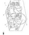
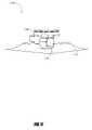
- FIG. 1shows a home with zoned heating and cooling.
- FIG. 2shows one example of a conventional manually-controlled register vent.
- FIG. 3Ais a front view of one embodiment of an electronically-controlled register vent.
- FIG. 3Bis a rear view of the electronically-controlled register vent shown in FIG. 3A .
- FIG. 4is a block diagram of a self-contained ECRV.
- FIG. 5is a block diagram of a self-contained ECRV with a remote control.
- FIG. 6is a block diagram of a locally-controlled zoned heating and cooling system wherein a zone thermostat controls one or more ECRVs.
- FIG. 7Ais a block diagram of a centrally-controlled zoned heating and cooling system wherein the central control system communicates with one or more zone thermostats and one or more ECRVs independently of the HVAC system.
- FIG. 7Bis a block diagram of a centrally-controlled zoned heating and cooling system wherein the central control system communicates with one or more zone thermostats and the zone thermostats communicate with one or more ECRVs.
- FIG. 8is a block diagram of a centrally-controlled zoned heating and cooling system wherein a central control system communicates with one or more zone thermostats and one or more ECRVs and controls the HVAC system.
- FIG. 9is a block diagram of an efficiency-monitoring centrally-controlled zoned heating and cooling system wherein a central control system communicates with one or more zone thermostats and one or more ECRVs and controls and monitors the HVAC system.
- FIG. 10is a block diagram of an ECRV for use in connection with the systems shown in FIGS. 6–9 .
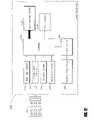
- FIG. 11is a block diagram of a basic zone thermostat for use in connection with the systems shown in FIGS. 6–9 .
- FIG. 12is a block diagram of a zone thermostat with remote control for use in connection with the systems shown in FIGS. 6–9 .
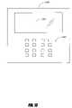
- FIG. 13shows one embodiment of a central monitoring system.
- FIG. 14is a flowchart showing one embodiment of an instruction loop for an ECRV or zone thermostat.
- FIG. 15is a flowchart showing one embodiment of an instruction and sensor data loop for an ECRV or zone thermostat.
- FIG. 16is a flowchart showing one embodiment of an instruction and sensor data reporting loop for an ECRV or zone thermostat.
- FIG. 17shows an ECRV configured to be used in connection with a conventional T-bar ceiling system found in many commercial structures.
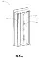
- FIG. 18shows an ECRV configured to use a scrolling curtain to control airflow as an alternative to the vanes shown in FIGS. 2 and 3 .
- FIG. 19is a block diagram of a control algorithm for controlling the register vents.
- FIG. 1shows a home 100 with zoned heating and cooling.
- an HVAC systemprovides heating and cooling air to a system of ducts.
- Sensors 101 – 105monitor the temperature in various areas (zones) of the house.
- a zonecan be a room, a floor, a group of rooms, etc.
- the sensors 101 – 105detect where and when heating or cooling air is needed.
- Information from the sensors 101 – 105is used to control actuators that adjust the flow of air to the various zones.
- the zoned systemadapts to changing conditions in one area without affecting other areas. For example, many two-story houses are zoned by floor. Because heat rises, the second floor usually requires more cooling in the summer and less heating in the winter than the first floor.
- a non-zoned systemcannot completely accommodate this seasonal variation. Zoning, however, can reduce the wide variations in temperature between floors by supplying heating or cooling only to the space that needs it.
- FIG. 2shows one example of a conventional manually-controlled register vent 200 .
- the register 200includes one or more vanes 201 that can be opened or closed to adjust the amount of air that flows through the register 200 .
- Diverters 202direct the air in a desired direction (or directions).
- the vanes 201are typically provided to a mechanical mechanism so that the occupants can manipulate the vanes 201 to control the amount of air that flows out of the register. 200 .
- the diverters 202are fixed.
- the diverters 202are moveable to allow the occupants some control over the direction of the airflow out of the vent.
- Registers such as the register 200are found throughout homes that have a central HVAC system that provides heating and cooling air.
- relatively small roomssuch as bedrooms and bathrooms will have one or two such register vents of varying sizes.
- Larger rooms, such as living rooms, family rooms, etc.may have more than two such registers.
- the occupants of a homecan control the flow of air through each of the vents by manually adjusting the vanes 201 .
- the register ventis located on the floor, or relatively low on the wall, such adjustment is usually not particularly difficult (unless the mechanism that controls the vanes 201 is bent or rusted).
- adjustment of the vanes 201can be very difficult when the register vent 200 is located so high on the wall that it cannot be easily reached.
- FIG. 3shows one embodiment of an Electronically-Controlled Register Vent (ECRV) 300 .
- the ECRV 300can be used to implement a zoned heating and cooling system.
- the ECRV 300can also be used as a remotely control register vent in places where the vent is located so high on the wall that is cannot be easily reached.
- the ECRV 300is configured as a replacement for the vent 200 . This greatly simplifies the task of retrofitting a home by replacing one or more of the register vents 200 with the ECRVs 300 .
- the ECRV 300is configured to fit into approximately the same size duct opening as the conventional register vent 200 .
- the ECRV 300is configured to fit over the duct opening used by the conventional register vent 200 .
- the ECRV 300is configured to fit over the conventional register 200 , thereby allowing the register 200 to be left in place.
- a control panel 301provides one or more visual displays and, optionally, one or more user controls.
- a housing 302is provided to house an actuator to control the vanes 201 . In one embodiment, the housing 302 can also be used to house electronics, batteries, etc.
- FIG. 4is a block diagram of a self-contained ECRV 400 , which is one embodiment of the ECRV 300 shown in FIGS. 3A and 3B and the ECRV shown in FIG. 18 .
- a temperature sensor 406 and a temperature sensor 416are provided to a controller 401 .
- the controller 401controls an actuator system 409 .
- the actuator system 409provided mechanical movements to control the airflow through the vent.
- the actuator system 409includes an actuator provided to the vanes 201 or other air-flow devices to control the amount of air that flows through the ECRV 400 (e.g., the amount of air that flows from the duct into the room).
- an actuator systemincludes an actuator provided to one or more of the diverters 202 to control the direction of the airflow.
- the controller 401also controls a visual display 403 and an optional fan 402 .
- a user input device 408is provided to allow the user to set the desired room temperature.
- An optional sensor 407is provided to the controller 401 .
- the sensor 407includes an air pressure and/or airflow sensor.
- the sensor 407includes a humidity sensor.
- a power source 404provides power to the controller 401 , the fan 402 , the display 403 , the temperature sensors 406 , 416 , the sensor 407 , and the user input device 408 as needed.
- the controller 401controls the amount of power provided to the fan 402 , the display 403 , the sensor 406 , the sensor 416 , the sensor 407 , and the user input device 408 .
- an optional auxiliary power source 405is also provided to provide additional power.
- the auxiliary power sourceis a supplementary source of electrical power, such as, for example, a battery, a solar cell, an airflow (e.g., wind-powered) generator, the fan 402 acting as a generator, a nuclear-based electrical generator, a fuel cell, a thermocouple, etc.
- the power source 404is based on a non-rechargeable battery and the auxiliary power source 405 includes a solar cell and a rechargeable battery.
- the controller 401draws power from the auxiliary power source when possible to conserve power in the power source 404 .
- the controller 401also draws power from the power source 404 .
- the power source 404is configured as a rechargeable battery and the auxiliary power source 405 is configured as a solar cell that recharges the power source 404 .
- the display 403includes a flashing indicator (e.g., a flashing LED or LCD) when the available power from the power sources 404 and/or 405 drops below a threshold level.
- a flashing indicatore.g., a flashing LED or LCD
- the home occupantsuse the user input device 408 to set a desired temperature for the vicinity of the ECRV 400 .
- the display 403shows the setpoint temperature. In one embodiment, the display 403 also shows the current room temperature.
- the temperature sensor 406measures the temperature of the air in the room, and the temperature sensor 416 measures the temperature of the air in the duct. If the room temperature is above the setpoint temperature, and the duct air temperature is below the room temperature, then the controller 401 causes the actuator 409 to open the vent. If the room temperature is below the setpoint temperature, and the duct air temperature is above the room temperature, then the controller 401 causes the actuator 409 to open the vent. Otherwise, the controller 401 causes the actuator 409 to close the vent.
- the controller 401opens the vent to allow air into the room.
- the controller 401closes the vent.
- the controller 401is configured to provide a few degrees of hysteresis (often referred to as a thermostat deadband) around the setpoint temperature in order to avoid wasting power by excessive opening and closing of the vent.
- a thermostat deadbanda few degrees of hysteresis
- the controller 401turns on the fan 402 to pull additional air from the duct.
- the fan 402is used when the room temperature is relatively far from the setpoint temperature in order to speed the movement of the room temperature towards the setpoint temperature.
- the fan 402is used when the room temperature is changing relatively slowly in response to the open vent.
- the fan 402is used when the room temperature is moving away from the setpoint and the vent is fully open.
- the controller 401does not turn on or run the fan 402 unless there is sufficient power available from the power sources 404 , 405 .
- the controller 401measures the power level of the power sources 404 , 405 before turning on the fan 402 , and periodically (or continually) when the fan is on.
- the controller 401also does not turn on the fan 402 unless it senses that there is airflow in the duct (indicating that the HVAC air-handler fan is blowing air into the duct).
- the sensor 407includes an airflow sensor.
- the controller 401uses the fan 402 as an airflow sensor by measuring (or sensing) voltage generated by the fan 402 rotating in response to air flowing from the duct through the fan and causing the fan to act as a generator. In one embodiment, the controller 401 periodically stop the fan and checks for airflow from the duct.
- the senor 406includes a pressure sensor configured to measure the air pressure in the duct. In one embodiment, the sensor 406 includes a differential pressure sensor configured to measure the pressure difference between the air in the duct and the air outside the ECRV (e.g., the air in the room). Excessive air pressure in the duct is an indication that too many vents may be closed (thereby creating too much back pressure in the duct and reducing airflow through the HVAC system). In one embodiment, the controller 401 opens the vent when excess pressure is sensed.
- the controller 401conserves power by turning off elements of the ECRV 400 that are not in use.
- the controller 401monitors power available from the power sources 404 , 405 . When available power drops below a low-power threshold value, the controls the actuator 409 to an open position, activates a visual indicator using the display 403 , and enters a low-power mode. In the low power mode, the controller 401 monitors the power sources 404 , 405 but the controller does not provide zone control functions (e.g., the controller does not close the actuator 409 ). When the controller senses that sufficient power has been restored (e.g., through recharging of one or more of the power sources 404 , 405 , then the controller 401 resumes normal operation.
- FIG. 5is a block diagram of a self-contained ECRV 500 with a remote control interface 501 .
- the ECRV 500includes the power sources 404 , 405 , the controller 401 , the fan 402 , the display 403 , the temperature sensors 406 , 416 , the sensor 407 , and the user input device 408 .
- the remote control interface 501is provided to the controller 401 , to allow the controller 401 to communicate with a remote control 502 .
- the controller 502sends wireless signals to the remote control interface 501 using wireless communication such as, for example, infrared communication, ultrasonic communication, and/or radio-frequency communication.
- the communicationis one-way, from the remote control 502 to the controller 401 .
- the remote control 502can be used to set the temperature setpoint, to instruct the controller 401 to open or close the vent (either partially or fully), and/or to turn on the fan.
- the communication between the remote control 502 and the controller 401is two-way communication. Two-way communication allows the controller 401 to send information for display on the remote control 502 , such as, for example, the current room temperature, the power status of the power sources 404 , 405 , diagnostic information, etc.
- FIG. 6is a block diagram of a locally-controlled zoned heating and cooling system 600 wherein a zone thermostat 601 monitors the temperature of a zone 608 .
- ECRVs 602 , 603are configured to communicate with the zone thermostat 601 .
- One embodiment of the ECRVs 620 – 603is shown, for example, in connection with FIG. 10 .
- the zone thermostat 601sends control commands to the ECRVs 602 – 603 to cause the ECRVs 602 – 603 to open or close. In one embodiment, the zone thermostat 601 sends temperature information to the ECRVs 602 – 603 and the ECRVs 602 – 603 determine whether to open or close based on the temperature information received from the zone thermostat 601 . In one embodiment, the zone thermostat 601 sends information regarding the current zone temperature and the setpoint temperature to the ECRVs 602 – 603 .
- the ECRV 602communicates with the ECRV 603 in order to improve the robustness of the communication in the system 600 .
- the ECRV 603can act as a router between the ECRV 602 and the zone thermostat 601 .
- the ECRV 602 and the ECRV 603communicate to arbitrate opening and closing of their respective vents.
- FIG. 7Ais a block diagram of a centrally-controlled zoned heating and cooling system wherein a central control system 710 communicates with one or more zone thermostats 707 708 and one or more ECRVs 702 – 705 .
- the zone thermostat 707measures the temperature of a zone 711
- the ECRVs 702 , 703regulate air to the zone 711 .
- the zone thermostat 708measures the temperature of a zone 712
- the ECRVs 704 , 705regulate air to the zone 711 .
- a central thermostat 720controls the HVAC system 720 .
- FIG. 7Bis a block diagram of a centrally-controlled zoned heating and cooling system 750 that is similar to the system 700 shown in FIG. 7A .
- the central system 710communicates with the zone thermostats 707 , 708
- the zone thermostat 707communicates with the ECRVs 702 , 703
- the zone thermostat 708communicates with the ECRVs 704 , 705
- the central system 710communicates with the ECRVs 706 , 707 .
- the ECRVs 702 – 705are in zones that are associated with the respective zone thermostat 707 , 708 that controls the respective ECRVs 702 – 705 .
- the ECRVs 706 , 707are not associated with any particular zone thermostat and are controlled directly by the central system 710 .
- One of ordinary skill in the artwill recognize that the communication topology shown in FIG. 7B can also be used in connection with the system shown in FIGS. 8 and 9 .
- the central system 710controls and coordinates the operation of the zones 711 and 712 , but the system 710 does not control the HVAC system 721 .
- the central system 710operates independently of the thermostat 720 .
- the thermostat 720is provided to the central system 710 so that the central system 710 knows when the thermostat is calling for heating, cooling, or fan.
- the central system 710coordinates and prioritizes the operation of the ECRVs 702 – 705 .
- the home occupantsand provide a priority schedule for the zones 711 , 712 based on whether the zones are occupied, the time of day, the time of year, etc.
- zone 711can be given a relatively lower priority during the day and a relatively higher priority during the night.
- zone 712can be given a higher priority in summer (since upper floors tend to be harder to cool) and a lower priority in winter (since lower floors tend to be harder to heat).
- the occupantscan specify a weighted priority between the various zones.
- the central system 710can coordinate how many vents are closed (or partially closed) and thus, ensure that enough vents are open to maintain proper airflow through the system.
- the central system 710can also manage airflow through the home such that upper floors receive relatively more cooling air and lower floors receive relatively more heating air.
- FIG. 8is a block diagram of a centrally-controlled zoned heating and cooling system 800 .
- the system 800is similar to the system 700 and includes the zone thermostats 707 , 708 to monitor the zones 711 , 712 , respectively, and the ECRVs 702 – 705 .
- the zone thermostats 707 , 708 and/or the ECRVs 702 – 705communicate with a central controller 810 .
- the thermostat 720is provided to the central system 810 and the central system 810 controls the HVAC system 721 directly.
- the controller 810provides similar functionality as the controller 710 . However, since the controller 810 also controls the operation of the HVAC system 721 , the controller 810 is better able to call for heating and cooling as needed to maintain the desired temperature of the zones 711 , 712 . If all, or substantially, all of the home is served by the zone thermostats and ECRVs, then the central thermostat 720 can be eliminated.
- the controller 810can turn on the HVAC fan (without heating or cooling) to move air from zones that are too hot to zones that are too cool (or vice versa) without calling for heating or cooling.
- the controller 810can also provide for efficient use of the HVAC system by calling for heating and cooling as needed, and delivering the heating and cooling to the proper zones in the proper amounts. If the HVAC system 721 provides multiple operating modes (e.g., high-speed, low-speed, etc.), then the controller 810 can operate the HVAC system 721 in the most efficient mode that provides the amount of heating or cooling needed.
- FIG. 9is a block diagram of an efficiency-monitoring centrally-controlled zoned heating and cooling system 900 .
- the system 900is similar to the system 800 .
- the controller 810is replaced by an efficiency-monitoring controller 910 that is configured to receive sensor data (e.g., system operating temperatures, etc.) from the HVAC system 721 to monitor the efficiency of the HVAC system 721 .
- sensor datae.g., system operating temperatures, etc.
- FIG. 10is a block diagram of an ECRV 1000 for use in connection with the systems shown in FIGS. 6–9 .
- the ECRV 1000includes the power sources 404 , 405 , the controller 401 , the fan 402 , the display 403 , and, optionally the temperature sensors 416 and the sensor 407 , and the user input device 408 .
- a communication system 1081is provided to the controller 401 .
- the remote control interface 501is provided to the controller 401 , to allow the controller 401 to communicate with a remote control 502 .
- the controller 502sends wireless signals to the remote control interface 501 using wireless communication such as, for example, infrared communication, ultrasonic communication, and/or radio-frequency communication.
- the communication system 1081is configured to communicate with the zone thermometer and, optionally, with the central controllers 710 , 810 , 910 .
- the communication system 1081is configured to communicate using wireless communication such as, for example, infrared communication, radio communication, or ultrasonic communication.
- FIG. 11is a block diagram of a basic zone thermostat 1100 for use in connection with the systems shown in FIGS. 6–9 .
- a temperature sensor 1103is provided to a controller 1101 .
- User input controls 1102are also provided to the controller 1101 to allow the user to specify a setpoint temperature.
- a visual display 1110is provided to the controller 1101 .
- the controller 1101uses the visual display 1110 to show the current temperature, setpoint temperature, power status, etc.
- the communication system 1181is also provided to the controller 1101 .
- the power source 404 and, optionally, 405are provided to provide power for the controller 1100 , the controls 1101 , the sensor 1103 , the communication system 1181 , and the visual display 1110 .
- the communication method used by the zone thermostat 1100 to communicate with the ECRV 1000need not be the same method used by the zone thermostat 1100 to communicate with the central controller 710 , 810 , 910 .
- the communication system 1181is configured to provide one type of communication (e.g., infrared, radio, ultrasonic) with the central controller, and a different type of communication with the ECRV 1000 .
- the zone thermostatis battery powered. In one embodiment, the zone thermostat is configured into a standard light switch and receives electrical power from the light switch circuit.
- FIG. 12is a block diagram of a zone thermostat 1200 with remote control for use in connection with the systems shown in FIGS. 6–9 .
- the thermostat 1200is similar to the thermostat 1100 and includes, the temperature sensor 1102 , the input controls 1103 , the visual display 1110 , the communication system 1181 , and the power sources 404 , 405 .
- the remote control interface 501is provided to the controller 1101 .
- an occupant sensor 1201is provided to the controller 1101 .
- the occupant sensor 1201such as, for example, an infrared sensor, motion sensor, ultrasonic sensor, etc. senses when the zone is occupied.
- the occupantscan program the zone thermostat 1201 to bring the zone to different temperatures when the zone is occupied and when the zone is empty.
- the occupantscan program the zoned thermostat 1201 to bring the zone to different temperatures depending on the time of day, the time of year, the type of room (e.g. bedroom, kitchen, etc.), and/or whether the room is occupied or empty.
- a group of zonesare combined into a composite zone (e.g., a group of zones such as an entire house, an entire floor, an entire wing, etc.) and the central system 710 , 810 , 910 changes the temperature setpoints of the various zones according to whether the composite zone is empty or occupied.
- a composite zonee.g., a group of zones such as an entire house, an entire floor, an entire wing, etc.
- FIG. 13shows one embodiment of a central monitoring station console 1300 for accessing the functions represented by the blocks 710 , 810 , 910 in FIGS. 7 , 8 , 9 , respectively.
- the station 1300includes a display 1301 and a keypad 1302 .
- the occupantscan specify zone temperature settings, priorities, and thermostat deadbands using the central system 1300 and/or the zone thermostats.
- the console 1300is implemented as a hardware device.
- the console 1300is implemented in software as a computer display, such as, for example, on a personal computer.
- the zone control functions of the blocks 710 , 810 , 910are provided by a computer program running on a control system processor, and the control system processor interfaces with personal computer to provide the console 1300 on the personal computer. In one embodiment, the zone control functions of the blocks 710 , 810 , 910 are provided by a computer program running on a control system processor provided to a hardware console 1300 . In one embodiment, the occupants can use the Internet, telephone, cellular telephone, pager, etc. to remotely access the central system to control the temperature, priority, etc. of one or more zones.
- FIG. 14is a flowchart showing one embodiment of an instruction loop process 1400 for an ECRV or zone thermostat.
- the process 1400begins at a power-up block 1401 . After power up, the process proceeds to an initialization block 1402 . After initialization, the process advances to a “listen” block 1403 wherein the ECRV or zone thermostat listens for one or more instructions. If a decision block 1404 determines that an instruction has been received, then the process advances to a “perform instruction” block 1405 , otherwise the process returns to the listen block 1403 .
- the instructionscan include: open vent, close vent, open vent to a specified partially-open position, report sensor data (e.g., airflow, temperature, etc.), report status (e.g, battery status, vent position, etc.), and the like.
- report sensor datae.g., airflow, temperature, etc.
- report statuse.g, battery status, vent position, etc.
- the instructionscan include: report temperature sensor data, report temperature rate of change, report setpoint, report status, etc.
- the instructionscan also include: report number of ECRVs, report ECRV data (e.g., temperature, airflow, etc.), report ECRV vent position, change ECRV vent position, etc.
- the listen block 1403consumes relatively little power, thereby allowing the ECRV or zone thermostat to stay in the loop corresponding to the listen block 1403 and conditional branch 1404 for extended periods of time.
- FIG. 15is a flowchart showing one embodiment of an instruction and sensor data loop process 1500 for an ECRV or zone thermostat.
- the process 1500begins at a power-up block 1501 . After power up, the process proceeds to an initialization block 1502 . After initialization, the process advances to a “sleep” block 1503 wherein the ECRV or zone thermostat sleeps for a specified period of time. When the sleep period expires, the process advances to a wakeup block 1504 and then to a decision 1505 . In the decision block 1505 , if a fault is detected, then a transmit fault block 1506 is executed.
- the processthen advances to a sensor block 1507 where sensor readings are taken. After taking sensor readings, the process advances to a listen-for-instructions block 1508 . If an instruction has been received, then the process advances to a “perform instruction” block 1510 ; otherwise, the process returns to the sleep block 1503 .
- FIG. 16is a flowchart showing one embodiment of an instruction and sensor data reporting loop process 1600 for an ECRV or zone thermostat.
- the process 1600begins at a power-up block 1601 . After power up, the process proceeds to an initialization block 1602 . After initialization, the process advances to a check fault block 1603 . If a fault is detected then a decision block 1604 advances the process to a transmit fault block 1605 ; otherwise, the process advances to a sensor block 1606 where sensor readings are taken. The data values from one or more sensors are evaluated, and if the sensor data is outside a specified range, or if a timeout period has occurred, then the process advances to a transmit data block 1608 ; otherwise, the process advances to a sleep block 1609 .
- the processAfter transmitting in the transmit fault block 1605 or the transmit sensor data block 1608 , the process advances to a listen block 1610 where the ECRV or zone thermostat listens for instructions. If an instruction is received, then a decision block advances the process to a perform instruction block 1612 ; otherwise, the process advances to the sleep block 1609 . After executing the perform instruction block 1612 , the process transmits an “instruction complete message” and returns to the listen block 1610 .
- FIGS. 14–16show different levels of interaction between devices and different levels of power conservation in the ECRV and/or zone thermostat.
- the ECRV and zone thermostatare configured to receive sensor data and user inputs, report the sensor data and user inputs to other devices in the zone control system, and respond to instructions from other devices in the zone control system.
- the process flows shown in FIGS. 14–16are provided for illustrative purposes and not by way of limitation. Other data reporting and instruction processing loops will be apparent to those of ordinary skill in the art by using the disclosure herein.
- the ECRV and/or zone thermostat“sleep,” between sensor readings.
- the central system 710sends out a “wake up” signal.
- an ECRV or zone thermostatreceives a wake up signal, it takes one or more sensor readings, encodes it into a digital signal, and transmits the sensor data along with an identification code.
- the ECRVis bi-directional and configured to receive instructions from the central system.
- the central systemcan instruct the ECRV to: perform additional measurements; go to a standby mode; wake up; report battery status; change wake-up interval; run self-diagnostics and report results; etc.
- the ECRVprovides two wake-up modes, a first wake-up mode for taking measurements (and reporting such measurements if deemed necessary), and a second wake-up mode for listening for commands from the central system.
- the two wake-up modes, or combinations thereof,can occur at different intervals.
- the ECRVsuse spread-spectrum techniques to communicate with the zone thermostats and/or the central system. In one embodiment, the ECRVs use frequency-hopping spread-spectrum. In one embodiment, each ECRV has an Identification code (ID) and the ECRVs attaches its ID to outgoing communication packets. In one embodiment, when receiving wireless data, each ECRV ignores data that is addressed to other ECRVs.
- IDIdentification code
- the ECRVprovides bi-directional communication and is configured to receive data and/or instructions from the central system.
- the central systemcan instruct the ECRV to perform additional measurements, to go to a standby mode, to wake up, to report battery status, to change wake-up interval, to run self-diagnostics and report results, etc.
- the ECRVreports its general health and status on a regular basis (e.g., results of self-diagnostics, battery health, etc.)
- the ECRVuse spread-spectrum techniques to communicate with the central system. In one embodiment, the ECRV uses frequency-hopping spread-spectrum. In one embodiment, the ECRV has an address or identification (ID) code that distinguishes the ECRV from the other ECRVs.
- IDidentification
- the ECRVattaches its ID to outgoing communication packets so that transmissions from the ECRV can be identified by the central system.
- the central systemattaches the ID of the ECRV to data and/or instructions that are transmitted to the ECRV. In one embodiment, the ECRV ignores data and/or instructions that are addressed to other ECRVs.
- the ECRVs, zone thermostats, central system, etc.communicate on a 900 MHz frequency band. This band provides relatively good transmission through walls and other obstacles normally found in and around a building structure.
- the ECRVs and zone thermostatscommunicate with the central system on bands above and/or below the 900 MHz band.
- the ECRVs and zone thermostatslisten to a radio frequency channel before transmitting on that channel or before beginning transmission. If the channel is in use, (e.g., by another device such as another central system, a cordless telephone, etc.) then the ECRVs and/or zone thermostats change to a different channel.
- the senorcentral system coordinates frequency hopping by listening to radio frequency channels for interference and using an algorithm to select a next channel for transmission that avoids the interference.
- the ECRV and/or zone thermostattransmits data until it receives an acknowledgement from the central system that the message has been received.
- Frequency-hopping wireless systemsoffer the advantage of avoiding other interfering signals and avoiding collisions. Moreover, there are regulatory advantages given to systems that do not transmit continuously at one frequency. Channel-hopping transmitters change frequencies after a period of continuous transmission, or when interference is encountered. These systems may have higher transmit power and relaxed limitations on in-band spurs.
- the controller 401reads the sensors 406 , 407 , 416 at regular periodic intervals. In one embodiment, the controller 401 reads the sensors 406 , 407 , 416 at random intervals. In one embodiment, the controller 401 reads the sensors 406 , 407 , 416 in response to a wake-up signal from the central system. In one embodiment, the controller 401 sleeps between sensor readings.
- the ECRVtransmits sensor data until a handshaking-type acknowledgement is received.
- the ECRVretransmits its data and waits for an acknowledgement.
- the ECRVcontinues to transmit data and wait for an acknowledgement until an acknowledgement is received.
- the ECRVaccepts an acknowledgement from a zone thermometer and it then becomes the responsibility of the zone thermometer to make sure that the data is forwarded to the central system.
- the two-way communication ability of the ECRV and zone thermometerprovides the capability for the central system to control the operation of the ECRV and/or zone thermometer and also provides the capability for robust handshaking-type communication between the ECRV, the zone thermometer, and the central system.
- the ECRVs 602 , 603send duct temperature data to the zone thermostat 601 .
- the zone thermostat 601compares the duct temperature to the room temperature and the setpoint temperature and makes a determination as to whether the ECRVs 602 , 603 should be open or closed.
- the zone thermostat 601then sends commands to the ECRVs 602 , 603 to open or close the vents.
- the zone thermostat 601displays the vent position on the visual display 1110 .
- the zone thermostat 601sends setpoint information and current room temperature information to the ECRVs 602 , 603 .
- the ECRVs 602 , 603compare the duct temperature to the room temperature and the setpoint temperature and makes a determination as to whether to open or close the vents.
- the ECRVs 602 , 603send information to the zone thermostat 601 regarding the relative position of the vents (e.g., open, closed, partially open, etc.).
- the zone thermostats 707 , 708send room temperature and setpoint temperature information to the central system.
- the zone thermostats 707 , 708also send temperature slope (e.g., temperature rate of rise or fall) information to the central system.
- the central systemknows whether the HVAC system is providing heating or cooling; otherwise, the central system used duct temperature information provide by the ECRVs 702 – 705 to determine whether the HVAC system is heating or cooling.
- ECRVssend duct temperature information to the central system.
- the central systemqueries the ECRVs by sending instructions to one or more of the ECRVs 702 – 705 instructing the ECRV to transmit its duct temperature.
- the central systemdetermines how much to open or close ECRVs 702 – 705 according to the available heating and cooling capacity of the HVAC system and according to the priority of the zones and the difference between the desired temperature and actual temperature of each zone.
- the occupantsuse the zone thermostat 707 to set the setpoint and priority of the zone 711 , the zone thermostat 708 to set the setpoint and priority of the zone 712 , etc.
- the occupantsuse the central system console 1300 to set the setpoint and priority of each zone, and the zone thermostats to override (either on a permanent or temporary basis) the central settings.
- the central console 1300displays the current temperature, setpoint temperature, temperature slope, and priority of each zone.
- the central systemallocates HVAC air to each zone according to the priority of the zone and the temperature of the zone relative to the setpoint temperature of the zone.
- the central systemprovides relatively more HVAC air to relatively higher priority zones that are not at their temperature setpoint than to lower priority zones or zones that are at or relatively near their setpoint temperature.
- the central systemavoids closing or partially closing too many vents in order to avoid reducing airflow in the duct below a desired minimum value.
- the central systemmonitors a temperature rate of rise (or fall) in each zone and sends commands to adjust the amount each ECRV 702 – 705 is open to bring higher priority zones to a desired temperature without allowing lower-priority zones to stray too far form their respective setpoint temperature.
- the central systemuses predictive modeling to calculate an amount of vent opening for each of the ECRVs 702 – 705 to reduce the number of times the vents are opened and closed and thereby reduce power usage by the actuators 409 .
- the central systemuses a neural network to calculate a desired vent opening for each of the ECRVs 702 – 705 .
- various operating parameterssuch as the capacity of the central HVAC system, the volume of the house, etc., are programmed into the central system for use in calculating vent openings and closings.
- the central systemis adaptive and is configured to learn operating characteristics of the HVAC system and the ability of the HVAC system to control the temperature of the various zones as the ECRVs 702 – 705 are opened and closed.
- the central systemcontrols the ECRVs to achieve the desired temperature over a period of time, the central system learns which ECRVs need to be opened, and by how much, to achieve a desired level of heating and cooling for each zone.
- the use of such an adaptive central systemis convenient because the installer is not required to program HVAC operating parameters into the central system.
- the central systemprovides warnings when the HVAC system appears to be operating abnormally, such as, for example, when the temperature of one or more zones does not change as expected (e.g., because the HVAC system is not operating properly, a window or door is open, etc.).
- the adaptation and learning capability of the central systemuses different adaptation results (e.g., different coefficients) based on whether the HVAC system is heating or cooling, the outside temperature, a change in the setpoint temperature or priority of the zones, etc.
- the central systemuses a first set of adaptation coefficients when the HVAC system is cooling, and a second set of adaptation coefficients when the HVAC system is heating.
- the adaptationis based on a predictive model.
- the adaptationis based on a neural network.
- FIG. 17shows an ECRV 1700 configured to be used in connection with a conventional T-bar ceiling system found in many commercial structures.
- an actuator 1701(as one embodiment of the actuator 409 ) is provided to a damper 1702 .
- the damper 1702is provided to a diffuser 1703 that is configured to mount in a conventional T-bar ceiling system.
- the ECRV 1700can be connected to a zoned thermostat or central system by wireless or wired communication.
- the sensors 407 in the ECRVsinclude airflow and/or air velocity sensors. Data from the sensors 407 are transmitted by the ECRV to the central system.
- the central systemuses the airflow and/or air velocity measurements to determine the relative amount of air through each ECRV.
- the central systemcan adapt to the relatively lower airflow of smaller ECRVs and ECRVs that are situated on the duct further from the HVAC blower than ECRVs which are located closer to the blower (the closer ECRVs tend to receive more airflow).
- FIG. 18shows a register vent 1800 configured to use a scrolling curtain 1801 to control airflow as an alternative to the vanes shown in FIGS. 2 and 3 .
- An actuator 1802(one embodiment of the actuator 409 ) is provided to the curtain 1801 to move the curtain 1801 across the register to control the size of a register airflow opening.
- the curtain 1801is guided and held in position by a track 1803 .
- the actuator 1802is a rotational actuator and the scrolling curtain 1801 is rolled around the actuator 1802 , and the register vent 1800 is open and rigid enough to be pushed into the vent opening by the actuator 1802 when the actuator 1802 rotates to unroll the curtain 1801 .
- the actuator 1802is a rotational actuator and the scrolling curtain 1801 is rolled around the actuator 1802 , and the register vent 1800 is open and rigid enough to be pushed into the vent opening by the actuator 1802 when the actuator 1802 rotates to unroll the curtain 1801 .
- the actuator 1802is configured to
- FIG. 19is a block diagram of a control algorithm 1900 for controlling the register vents.
- the algorithm 1900is described herein as running on the central system. However, one of ordinary skill in the art will recognize that the algorithm 1900 can be run by the central system, by the zone thermostat, by the ECRV, or the algorithm 1900 can be distributed among the central system, the zone thermostat, and the ECRV.
- the algorithm 1900in a block 1901 of the algorithm 1900 , the setpoint temperatures from one or more zone thermostats are provided to a calculation block 1902 .
- the calculation block 1902calculates the register vent settings (e.g., how much to open or close each register vent) according to the zone temperature, the zone priority, the available heating and cooling air, the previous register vent settings, etc. as described above. In one embodiment, the block 1902 uses a predictive model as described above. In one embodiment, the block 1902 calculates the register vent settings for each zone independently (e.g., without regard to interactions between zones). In one embodiment, the block 1902 calculates the register vent settings for each zone in a coupled-zone manner that includes interactions between zones. In one embodiment, the calculation block 1902 calculates new vent openings by taking into account the current vent openings and in a manner configured to minimize the power consumed by opening and closing the register vents.
- the register vent settingse.g., how much to open or close each register vent
- Register vent settings from the block 1902are provided to each of the register vent actuators in a block 1903 , wherein the register vents are moved to new opening positions as desired (and, optionally, one or more of the fans 402 are turned on to pull additional air from desired ducts).
- the processadvances to a block 1904 where new zone temperatures are obtained from the zone thermostats (the new zone temperatures being responsive to the new register vent settings made in block 1903 ).
- the new zone temperaturesare provided to an adaptation input of the block 1902 to be used in adapting a predictive model used by the block 1902 .
- the new zone temperaturesalso provided to a temperature input of the block 1902 to be used in calculating new register vent settings.
- the algorithm used in the calculation block 1902is configured to predict the ECRV opening needed to bring each zone to the desired temperature based on the current temperature, the available heating and cooling, the amount of air available through each ECRV, etc.
- the calculating blockuses the prediction model to attempt to calculate the ECRV openings needed for relatively long periods of time in order to reduce the power consumed in unnecessarily by opening and closing the register vents.
- the ECRVsare battery powered, and thus reducing the movement of the register vents extends the life of the batteries.
- the block 1902uses a predictive model that learns the characteristics of the HVAC system and the various zones and thus the model prediction tends to improve over time.
- the zone thermostatsreport zone temperatures to the central system and/or the ECRVs at regular intervals. In one embodiment, the zone thermostats report zone temperatures to the central system and/or the ECRVs after the zone temperature has changed by a specified amount specified by a threshold value. In one embodiment, the zone thermostats report zone temperatures to the central system and/or the ECRVs in response to a request instruction from the central system or ECRV.
- the zone thermostatsreport setpoint temperatures and zone priority values to the central system or ECRVs whenever the occupants change the setpoint temperatures or zone priority values using the user controls 1102 . In one embodiment, the zone thermostats report setpoint temperatures and zone priority values to the central system or ECRVs in response to a request instruction from the central system or ECRVs.
- the occupantscan choose the thermostat deadband value (e.g., the hysteresis value) used by the calculation block 1902 .
- the thermostat deadband valuee.g., the hysteresis value
- a relatively larger deadband valuereduces the movement of the register vent at the expense of larger temperature variations in the zone.
- the ECRVsreport sensor data (e.g., duct temperature, airflow, air velocity, power status, actuator position, etc.) to the central system and/or the zone thermostats at regular intervals. In one embodiment, the ECRVs report sensor data to the central system and/or the zone thermostats whenever the sensor data fails a threshold test (e.g., exceeds a threshold value, falls below a threshold value, falls inside a threshold range, or falls outside a threshold range, etc.). In one embodiment, the ECRVs report sensor data to the central system and/or the zone thermostats in response to a request instruction from the central system or zone thermostat.
- sensor datae.g., duct temperature, airflow, air velocity, power status, actuator position, etc.
- the fans 402can be used as generators to provide power to recharge the power source 404 in the ECRV. However, using the fan 402 in such a manner restricts airflow through the ECRV.
- the controller 401calculates a vent opening for the ECRV to produce the desired amount of air through the ECRV while using the fan to generate power to recharge the power source 404 (thus, in such circumstance) the controller would open the vanes more than otherwise necessary in order to compensate for the air resistance of the generator fan 402 .
- the controller 401in order to save power in the ECRV, rather than increase the vane opening, the controller 401 can use the fan as a generator.
- the controller 401can direct the power generated by the fan 402 into one or both of the power sources 404 , 405 , or the controller 401 can dump the excess power from the fan into a resistive load. In one embodiment, the controller 401 makes decisions regarding vent opening versus fan usage. In one embodiment, the central system instructs the controller 401 when to use the vent opening and when to use the fan. In one embodiment, the controller 401 and central system negotiate vent opening versus fan usage.
- the ECRVreports its power status to the central system or zone thermostat.
- the central system or zone thermostattakes such power status into account when determining new ECRV openings.
- the central systemwill use the second ECRV to modulate the air into the zone. If the first ECRV is able to use the fan 402 or other airflow-based generator to generate electrical power, the central system will instruct the second ECRV to a relatively closed position in and direct relatively more airflow through the first ECRV when directing air into the zone.
- the central systemis shown in FIGS. 7–9 is implemented in a distributed fashion in the zone thermostats 1100 and/or in the ECRVs.
- the central systemdoes not necessarily exists as a distinct device, rather, the functions of the central system can be are distributed in the zone thermostats 1100 and/or the ECRVs.
- FIGS. 7–9represent a conceptual/computational model of the system. For example, in a distributed system, each zone thermostat 100 knows its zone priority, and the zone thermostats 1100 in the distributed system negotiate to allocate the available heating/cooling air among the zones.
- one of the zone thermostatassumes the role of a master thermostat that collects data from the other zone thermostats and implements the calculation block 1902 .
- the zone thermostatsoperate in a peer-to-peer fashion, and the calculation block 1902 is implemented in a distributed manner across a plurality of zone thermostats and/or ECRVs.
- the wireless systemcan be configured to operate on one or more frequency bands, such as, for example, the HF band, the VHF band, the UHF band, the Microwave band, the Millimeter wave band, etc.
- modulation usesis not limited to any particular modulation method, such that modulation scheme used can be, for example, frequency modulation, phase modulation, amplitude modulation, combinations thereof, etc.
- modulation scheme usedcan be, for example, frequency modulation, phase modulation, amplitude modulation, combinations thereof, etc.
- the one or more of the wireless communication systems described abovecan be replaced by wired communication.
- the one or more of the wireless communication systems described abovecan be replaced by powerline networking communication.
Landscapes
- Engineering & Computer Science (AREA)
- Combustion & Propulsion (AREA)
- General Engineering & Computer Science (AREA)
- Mechanical Engineering (AREA)
- Chemical & Material Sciences (AREA)
- Physics & Mathematics (AREA)
- Human Computer Interaction (AREA)
- Signal Processing (AREA)
- Automation & Control Theory (AREA)
- General Physics & Mathematics (AREA)
- Fuzzy Systems (AREA)
- Mathematical Physics (AREA)
- Remote Sensing (AREA)
- Health & Medical Sciences (AREA)
- Biomedical Technology (AREA)
- Fluid Mechanics (AREA)
- Air Conditioning Control Device (AREA)
Abstract
Description
Claims (54)
Priority Applications (15)
| Application Number | Priority Date | Filing Date | Title |
|---|---|---|---|
| US10/959,494US7156316B2 (en) | 2004-10-06 | 2004-10-06 | Zone thermostat for zone heating and cooling |
| AU2005294681AAU2005294681A1 (en) | 2004-10-06 | 2005-09-08 | System and method for zone heating and cooling |
| RU2007114679/06ARU2007114679A (en) | 2004-10-06 | 2005-09-08 | SYSTEM AND METHOD FOR ZONE HEATING AND COOLING |
| PCT/US2005/032022WO2006041599A2 (en) | 2004-10-06 | 2005-09-08 | System and method for zone heating and cooling |
| EP05796084AEP1807660A2 (en) | 2004-10-06 | 2005-09-08 | System and method for zone heating and cooling |
| JP2007535688AJP2008516179A (en) | 2004-10-06 | 2005-09-08 | Section heating and cooling system and method |
| CA002582232ACA2582232A1 (en) | 2004-10-06 | 2005-09-08 | System and method for zone heating and cooling |
| MX2007003854AMX2007003854A (en) | 2004-10-06 | 2005-09-08 | System and method for zone heating and cooling. |
| US11/613,090US7455236B2 (en) | 2004-10-06 | 2006-12-19 | Zone thermostat for zone heating and cooling |
| IN8285DEN2014IN2014DN08285A (en) | 2004-10-06 | 2014-10-06 | |
| IN8288DEN2014IN2014DN08288A (en) | 2004-10-06 | 2014-10-06 | |
| IN8283DEN2014IN2014DN08283A (en) | 2004-10-06 | 2014-10-06 | |
| IN8287DEN2014IN2014DN08287A (en) | 2004-10-06 | 2014-10-06 | |
| IN8281DEN2014IN2014DN08281A (en) | 2004-10-06 | 2014-10-06 | |
| IN8284DEN2014IN2014DN08284A (en) | 2004-10-06 | 2014-10-06 |
Applications Claiming Priority (1)
| Application Number | Priority Date | Filing Date | Title |
|---|---|---|---|
| US10/959,494US7156316B2 (en) | 2004-10-06 | 2004-10-06 | Zone thermostat for zone heating and cooling |
Related Child Applications (1)
| Application Number | Title | Priority Date | Filing Date |
|---|---|---|---|
| US11/613,090ContinuationUS7455236B2 (en) | 2004-10-06 | 2006-12-19 | Zone thermostat for zone heating and cooling |
Publications (2)
| Publication Number | Publication Date |
|---|---|
| US20060071089A1 US20060071089A1 (en) | 2006-04-06 |
| US7156316B2true US7156316B2 (en) | 2007-01-02 |
Family
ID=36124581
Family Applications (2)
| Application Number | Title | Priority Date | Filing Date |
|---|---|---|---|
| US10/959,494Expired - LifetimeUS7156316B2 (en) | 2004-10-06 | 2004-10-06 | Zone thermostat for zone heating and cooling |
| US11/613,090Expired - LifetimeUS7455236B2 (en) | 2004-10-06 | 2006-12-19 | Zone thermostat for zone heating and cooling |
Family Applications After (1)
| Application Number | Title | Priority Date | Filing Date |
|---|---|---|---|
| US11/613,090Expired - LifetimeUS7455236B2 (en) | 2004-10-06 | 2006-12-19 | Zone thermostat for zone heating and cooling |
Country Status (1)
| Country | Link |
|---|---|
| US (2) | US7156316B2 (en) |
Cited By (123)
| Publication number | Priority date | Publication date | Assignee | Title |
|---|---|---|---|---|
| US20040194484A1 (en)* | 2002-11-07 | 2004-10-07 | Shazhou Zou | Affordable and easy to install multi-zone HVAC system |
| US20060185818A1 (en)* | 2005-02-23 | 2006-08-24 | Garozzo James P | System and method for controlling a multi-zone heating or cooling system |
| US20070095518A1 (en)* | 2004-10-06 | 2007-05-03 | Lawrence Kates | System and method for zone heating and cooling |
| US20070102149A1 (en)* | 2004-10-06 | 2007-05-10 | Lawrence Kates | Electronically-controlled register vent for zone heating and cooling |
| US20070119957A1 (en)* | 2004-10-06 | 2007-05-31 | Lawrence Kates | Zone thermostat for zone heating and cooling |
| US20080006708A1 (en)* | 2006-07-10 | 2008-01-10 | Kantengri Design, Ltd. | Move-a-thermostat system |
| US20080033599A1 (en)* | 2006-08-02 | 2008-02-07 | Rouzbeh Aminpour | Method and system for controlling heating ventilation and air conditioning (HVAC) units |
| US20080128523A1 (en)* | 2006-11-30 | 2008-06-05 | Honeywell International Inc. | Hvac zone control panel |
| US20080133060A1 (en)* | 2006-11-30 | 2008-06-05 | Honeywell International Inc. | Hvac zone control panel with checkout utility |
| US20080134087A1 (en)* | 2006-11-30 | 2008-06-05 | Honeywell International Inc. | Hvac zone control panel |
| US20080134098A1 (en)* | 2006-11-30 | 2008-06-05 | Honeywell International Inc. | Hvac zone control panel |
| US20080133033A1 (en)* | 2006-11-30 | 2008-06-05 | Honeywell International Inc. | Hvac zone control panel |
| US20080179052A1 (en)* | 2007-01-29 | 2008-07-31 | Lawrence Kates | System and method for budgeted zone heating and cooling |
| US20080223943A1 (en)* | 2007-03-15 | 2008-09-18 | Honeywell International Inc. | Variable Speed Blower Control In An HVAC System Having A Plurality of Zones |
| US20080251590A1 (en)* | 2007-04-13 | 2008-10-16 | Honeywell International Inc. | Hvac staging control |
| US20090065595A1 (en)* | 2007-09-12 | 2009-03-12 | Lawrence Kates | System and method for zone heating and cooling using controllable supply and return vents |
| US20090140057A1 (en)* | 2007-11-30 | 2009-06-04 | Honeywell International, Inc. | Display for hvac systems in remote control units |
| US20100012737A1 (en)* | 2008-07-21 | 2010-01-21 | Lawrence Kates | Modular register vent for zone heating and cooling |
| US20100070086A1 (en)* | 2008-09-15 | 2010-03-18 | Johnson Controls Technology Company | Indoor air quality controllers and user interfaces |
| US20100076605A1 (en)* | 2008-09-19 | 2010-03-25 | Johnson Controls Technology Company | HVAC System Controller Configuration |
| US20100078492A1 (en)* | 2009-08-20 | 2010-04-01 | Cislo Daniel M | Solar Powered Smart Ventilation System |
| US20100107083A1 (en)* | 2008-10-27 | 2010-04-29 | Lennox Industries Inc. | Memory recovery scheme and data structure in a heating, ventilation and air conditioning network |
| US20100107076A1 (en)* | 2008-10-27 | 2010-04-29 | Lennox Industries Incorporation | System and method of use for a user interface dashboard of a heating, ventilation and air conditioning network |
| US20100106957A1 (en)* | 2008-10-27 | 2010-04-29 | Lennox Industries Inc. | Programming and configuration in a heating, ventilation and air conditioning network |
| US20100107073A1 (en)* | 2008-10-27 | 2010-04-29 | Lennox Industries Inc. | System and method of use for a user interface dashboard of a heating, ventilation and air conditioning network |
| US20100106327A1 (en)* | 2008-10-27 | 2010-04-29 | Lennox Industries Inc. | Communication protocol system and method for a distributed-architecture heating, ventilation and air conditioning network |
| US20100106810A1 (en)* | 2008-10-27 | 2010-04-29 | Lennox Industries Inc. | Communication protocol system and method for a distributed-architecture heating, ventilation and air conditioning network |
| US20100106308A1 (en)* | 2008-10-27 | 2010-04-29 | Lennox Industries, Inc. | System and method for zoning a distributed-architecture heating, ventilation and air conditioning network |
| US20100106316A1 (en)* | 2008-10-27 | 2010-04-29 | Lennox Industries Inc. | Alarm and diagnostics system and method for a distributed architecture heating, ventilation and air conditioning network |
| US20100106314A1 (en)* | 2008-10-27 | 2010-04-29 | Lennox Industries Inc. | System recovery in a heating, ventilation and air conditioning network |
| US20100107103A1 (en)* | 2008-10-27 | 2010-04-29 | Lennox Industries Inc. | System and method of use for a user interface dashboard of a heating, ventilation and air conditioning network |
| US20100102973A1 (en)* | 2008-10-27 | 2010-04-29 | Lennox Industries, Inc. | Alarm and diagnostics system and method for a distributed-architecture heating, ventilation and air conditioning network |
| US20100107109A1 (en)* | 2008-10-27 | 2010-04-29 | Lennox Industries, Incorporated | System and method of use for a user interface dashboard of a heating, ventilation and air conditioning network |
| US20100106317A1 (en)* | 2008-10-27 | 2010-04-29 | Lennox Industries Inc. | Device abstraction system and method for a distributed- architecture heating, ventilation and air conditioning system |
| US20100106319A1 (en)* | 2008-10-27 | 2010-04-29 | Lennox Industries Inc. | Method of controlling equipment in a heating, ventilation and air conditioning network |
| US20100106324A1 (en)* | 2008-10-27 | 2010-04-29 | Lennox Industries Inc. | Communication protocol system and method for a distributed-architecture heating, ventilation and air conditioning network |
| US20100101854A1 (en)* | 2008-10-27 | 2010-04-29 | Lennox Industries Inc. | Flush wall mount thermostat and in-set mounting plate for a heating, ventilation and air conditioning system |
| US20100106307A1 (en)* | 2008-10-27 | 2010-04-29 | Lennox Industries Inc. | Device abstraction system and method for a distributed-architecture heating, ventilation and air conditioning system |
| US20100106311A1 (en)* | 2008-10-27 | 2010-04-29 | Lennox Industries Inc. | Alarm and diagnostics system and method for a distributed architecture heating, ventilation and conditioning network |
| US20100106309A1 (en)* | 2008-10-27 | 2010-04-29 | Lennox Industries Inc. | General control techniques in a heating, ventilation and air conditioning network |
| US20100107070A1 (en)* | 2008-10-27 | 2010-04-29 | Lennox Industries Incorporated | System and method of use for a user interface dashboard of a heating, ventilation and air conditioning network |
| US20100102136A1 (en)* | 2008-10-27 | 2010-04-29 | Lennox Industries Inc. | Alarm and diagnostics system and method for a distributed architecture heating, ventilation and air conditioning network |
| US20100106318A1 (en)* | 2008-10-27 | 2010-04-29 | Lennox Industries Inc. | Alarm and diagnostics system and method for a distributed- architecture heating, ventilation and air conditioning network |
| US20100106321A1 (en)* | 2008-10-27 | 2010-04-29 | Lennox Industries Inc. | Memory recovery scheme and data structure in a heating, ventilation and air conditioning network |
| US20100107110A1 (en)* | 2008-10-27 | 2010-04-29 | Lennox Industries Inc. | System and method of use for a user interface dashboard of a heating, ventilation and air conditioning network |
| US20100107007A1 (en)* | 2008-10-27 | 2010-04-29 | Lennox Industries Inc. | System recovery in a heating, ventilation and air conditioning network |
| US20100106787A1 (en)* | 2008-10-27 | 2010-04-29 | Lennox Industries Inc. | Communication protocol system and method for a distributed architecture heating, ventilation and air conditioning network |
| US20100107071A1 (en)* | 2008-10-27 | 2010-04-29 | Lennox Industries Inc. | System and method of use for a user interface dashboard of a heating, ventilation and air conditioning network |
| US20100106323A1 (en)* | 2008-10-27 | 2010-04-29 | Lennox Industries Inc. | Communication protocol system and method for a distributed-architecture heating, ventilation and air conditioning network |
| US20100106815A1 (en)* | 2008-10-27 | 2010-04-29 | Lennox Industries Inc. | Memory recovery scheme and data structure in a heating, ventilation and air conditioning network |
| US20100106313A1 (en)* | 2008-10-27 | 2010-04-29 | Lennox Industries Inc. | Device abstraction system and method for a distributed architecture heating, ventilation and air conditioning system |
| US20100106326A1 (en)* | 2008-10-27 | 2010-04-29 | Lennox Industries Inc. | Communication protocol system and method for a distributed-architecture heating, ventilation and air conditioning network |
| US20100106312A1 (en)* | 2008-10-27 | 2010-04-29 | Lennox Industries Inc. | Alarm and diagnostics system and method for a distributed-architecture heating, ventilation and air conditioning network |
| US20100106320A1 (en)* | 2008-10-27 | 2010-04-29 | Lennox Industries Inc. | Communication protocol system and method for a distributed-architecture heating, ventilation and air conditioning network |
| US20100102948A1 (en)* | 2008-10-27 | 2010-04-29 | Lennox Industries Inc. | Alarm and diagnostics system and method for a distributed architecture heating, ventilation and air conditioning network |
| US20100107112A1 (en)* | 2008-10-27 | 2010-04-29 | Lennox Industries Inc. | System and method of use for a user interface dashboard of a heating, ventilation and air conditioning network |
| US20100106925A1 (en)* | 2008-10-27 | 2010-04-29 | Lennox Industries Inc. | Programming and configuration in a heating, ventilation and air conditioning network |
| US20100107232A1 (en)* | 2008-10-27 | 2010-04-29 | Lennox Industries Inc. | Communication protocol system and method for a distributed-architecture heating, ventilation and air conditioning network |
| US20100106315A1 (en)* | 2008-10-27 | 2010-04-29 | Lennox Industries Inc. | System recovery in a heating, ventilation and air conditioning network |
| US20100107072A1 (en)* | 2008-10-27 | 2010-04-29 | Lennox Industries Inc. | System and method of use for a user interface dashboard of a heating, ventilation and air conditioning network |
| US7714731B2 (en) | 2007-06-22 | 2010-05-11 | Andrew Llc | Detection of air filter clogging and provision of emergency ventilation in an outdoor electronics cabinet cooled by ambient forced air |
| US20100163633A1 (en)* | 2008-12-30 | 2010-07-01 | Aquante Llc | Automatically Balancing Register for HVAC Systems |
| US20100179696A1 (en)* | 2008-10-27 | 2010-07-15 | Lennox Industries Inc. | Device abstraction system and method for a distributed-architecture heating, ventilation and air conditioning system |
| US20100258642A1 (en)* | 2008-09-22 | 2010-10-14 | Newcomer Douglas A | Enviromental control systems and methods of configuring environmental control systems |
| US20100305761A1 (en)* | 2008-10-11 | 2010-12-02 | Ralph Remsburg | Automatic Mold and Fungus Growth Inhibition System and Method |
| US20100323607A1 (en)* | 2008-09-22 | 2010-12-23 | Newcomer Douglas A | Environmental control systems and methods of configuring environmental control systems |
| US20110034120A1 (en)* | 2009-08-04 | 2011-02-10 | Olawale Solomon Jaiyeola | Intelligent Autonomous Climate Control and Appealing Environment Creation System and Device |
| US20110031322A1 (en)* | 2003-11-06 | 2011-02-10 | Shazhou Zou | Novel air regulation device and air conditioning system |
| US20110130881A1 (en)* | 2009-12-01 | 2011-06-02 | Denso Wave Incorporated | Central air-conditioning system |
| US7957839B2 (en) | 2006-12-29 | 2011-06-07 | Honeywell International Inc. | HVAC zone controller |
| US20110202180A1 (en)* | 2010-02-17 | 2011-08-18 | Lennox Industries, Incorporated | Auxiliary controller, a hvac system, a method of manufacturing a hvac system and a method of starting the same |
| US8033479B2 (en) | 2004-10-06 | 2011-10-11 | Lawrence Kates | Electronically-controlled register vent for zone heating and cooling |
| USD648642S1 (en) | 2009-10-21 | 2011-11-15 | Lennox Industries Inc. | Thin cover plate for an electronic system controller |
| USD648641S1 (en) | 2009-10-21 | 2011-11-15 | Lennox Industries Inc. | Thin cover plate for an electronic system controller |
| US20110295430A1 (en)* | 2010-05-26 | 2011-12-01 | Andrey Kouninski | Apparatus And Method For Managing Heating Or Cooling Of An Area In A Building |
| US20120072030A1 (en)* | 2007-10-04 | 2012-03-22 | Mountainlogic, Inc. | System and method of predictive occupancy room conditioning |
| US8352081B2 (en) | 2008-10-27 | 2013-01-08 | Lennox Industries Inc. | Communication protocol system and method for a distributed-architecture heating, ventilation and air conditioning network |
| EP2567669A1 (en) | 2011-09-09 | 2013-03-13 | Imris Inc. | Surgical tool for use in MR imaging |
| US8442693B2 (en) | 2008-10-27 | 2013-05-14 | Lennox Industries, Inc. | System and method of use for a user interface dashboard of a heating, ventilation and air conditioning network |
| US8452906B2 (en) | 2008-10-27 | 2013-05-28 | Lennox Industries, Inc. | Communication protocol system and method for a distributed-architecture heating, ventilation and air conditioning network |
| US8478447B2 (en) | 2010-11-19 | 2013-07-02 | Nest Labs, Inc. | Computational load distribution in a climate control system having plural sensing microsystems |
| US8548630B2 (en) | 2008-10-27 | 2013-10-01 | Lennox Industries, Inc. | Alarm and diagnostics system and method for a distributed-architecture heating, ventilation and air conditioning network |
| US8558179B2 (en) | 2011-10-21 | 2013-10-15 | Nest Labs, Inc. | Integrating sensing systems into thermostat housing in manners facilitating compact and visually pleasing physical characteristics thereof |
| US8607822B2 (en) | 2008-09-22 | 2013-12-17 | X-Changer, Llc. | Heating and air conditioning system |
| US8620841B1 (en) | 2012-08-31 | 2013-12-31 | Nest Labs, Inc. | Dynamic distributed-sensor thermostat network for forecasting external events |
| US8630741B1 (en) | 2012-09-30 | 2014-01-14 | Nest Labs, Inc. | Automated presence detection and presence-related control within an intelligent controller |
| US20140163766A1 (en)* | 2012-12-12 | 2014-06-12 | International Business Machines Corporation | System performance using cooling configuration information |
| US8774210B2 (en) | 2008-10-27 | 2014-07-08 | Lennox Industries, Inc. | Communication protocol system and method for a distributed-architecture heating, ventilation and air conditioning network |
| US8788100B2 (en) | 2008-10-27 | 2014-07-22 | Lennox Industries Inc. | System and method for zoning a distributed-architecture heating, ventilation and air conditioning network |
| US8855825B2 (en) | 2008-10-27 | 2014-10-07 | Lennox Industries Inc. | Device abstraction system and method for a distributed-architecture heating, ventilation and air conditioning system |
| US20140316586A1 (en)* | 2013-04-18 | 2014-10-23 | Robert Bosch Gmbh | Thermostat for a hvac |
| US9091453B2 (en) | 2012-03-29 | 2015-07-28 | Google Inc. | Enclosure cooling using early compressor turn-off with extended fan operation |
| US9098096B2 (en) | 2012-04-05 | 2015-08-04 | Google Inc. | Continuous intelligent-control-system update using information requests directed to user devices |
| US9208676B2 (en) | 2013-03-14 | 2015-12-08 | Google Inc. | Devices, methods, and associated information processing for security in a smart-sensored home |
| US9261888B2 (en) | 2008-10-27 | 2016-02-16 | Lennox Industries Inc. | System and method of use for a user interface dashboard of a heating, ventilation and air conditioning network |
| US9268344B2 (en) | 2010-11-19 | 2016-02-23 | Google Inc. | Installation of thermostat powered by rechargeable battery |
| US9432208B2 (en) | 2008-10-27 | 2016-08-30 | Lennox Industries Inc. | Device abstraction system and method for a distributed architecture heating, ventilation and air conditioning system |
| US9494952B2 (en) | 2011-03-31 | 2016-11-15 | Trane International Inc. | Systems and methods for controlling multiple HVAC systems |
| US9632490B2 (en) | 2008-10-27 | 2017-04-25 | Lennox Industries Inc. | System and method for zoning a distributed architecture heating, ventilation and air conditioning network |
| US9651273B2 (en) | 2014-05-30 | 2017-05-16 | Daniel Donovan | Programmable thermostat for a room |
| US10126009B2 (en) | 2014-06-20 | 2018-11-13 | Honeywell International Inc. | HVAC zoning devices, systems, and methods |
| US20190179268A1 (en)* | 2017-12-12 | 2019-06-13 | Distech Controls Inc. | Inference server and environment controller for inferring via a neural network one or more commands for controlling an appliance |
| US20190179269A1 (en)* | 2017-12-12 | 2019-06-13 | Distech Controls Inc. | Environment controller and method for inferring via a neural network one or more commands for controlling an appliance |
| US20190179270A1 (en)* | 2017-12-12 | 2019-06-13 | Distech Controls Inc. | Inference server and environment controller for inferring one or more commands for controlling an appliance taking into account room characteristics |
| US20190182069A1 (en)* | 2017-12-12 | 2019-06-13 | Distech Controls Inc. | Environment controller and method for inferring one or more commands for controlling an appliance taking into account room characteristics |
| US10393401B2 (en) | 2016-08-22 | 2019-08-27 | Air Distribution Technologies Ip, Llc | Direct drive motor integrated into damper blade |
| US10452083B2 (en) | 2010-11-19 | 2019-10-22 | Google Llc | Power management in single circuit HVAC systems and in multiple circuit HVAC systems |
| US10684633B2 (en) | 2011-02-24 | 2020-06-16 | Google Llc | Smart thermostat with active power stealing an processor isolation from switching elements |
| US10732651B2 (en) | 2010-11-19 | 2020-08-04 | Google Llc | Smart-home proxy devices with long-polling |
| US10771868B2 (en) | 2010-09-14 | 2020-09-08 | Google Llc | Occupancy pattern detection, estimation and prediction |
| US10830475B2 (en) | 2018-10-29 | 2020-11-10 | Johnson Controls Technology Company | Systems and methods for thermal storage in a zoning system |
| US10830479B2 (en) | 2018-05-18 | 2020-11-10 | Johnson Controls Technology Company | HVAC zone schedule management systems and methods |
| US10989427B2 (en) | 2017-12-20 | 2021-04-27 | Trane International Inc. | HVAC system including smart diagnostic capabilites |
| US11054160B2 (en) | 2015-07-01 | 2021-07-06 | Carrier Corporation | Simultaneous heating and cooling of multiple zones |
| US20210372636A1 (en)* | 2019-01-08 | 2021-12-02 | Johnson Controls Tyco IP Holdings LLP | Integrated zone control system |
| US11392098B2 (en) | 2018-10-29 | 2022-07-19 | Johnson Controls Tyco IP Holdings LLP | Priority systems and methods for a zoning system |
| US11506410B2 (en) | 2019-09-10 | 2022-11-22 | Johnson Controls Tyco IP Holdings LLP | Zone monitoring systems and methods for a zoning system |
| US11713895B2 (en) | 2019-01-14 | 2023-08-01 | Research Products Corporation | Multi-zone environmental control system |
| US20230383982A1 (en)* | 2022-05-26 | 2023-11-30 | Andrew Ian Braden Kremer | Motion Activated Vent Cover |
| US12000607B2 (en) | 2019-11-25 | 2024-06-04 | KEPsmart, Inc. | HVAC control system and method |
| US12140917B2 (en) | 2018-03-07 | 2024-11-12 | Distech Controls Inc. | Training server and method for generating a predictive model for controlling an appliance |
| US12264835B2 (en) | 2021-06-17 | 2025-04-01 | Research Products Corporation | Whole building air quality control system |
| US12410938B2 (en) | 2019-03-08 | 2025-09-09 | Tyco Fire & Security Gmbh | Damper control systems and methods for a zoning system |
Families Citing this family (60)
| Publication number | Priority date | Publication date | Assignee | Title |
|---|---|---|---|---|
| US7412842B2 (en) | 2004-04-27 | 2008-08-19 | Emerson Climate Technologies, Inc. | Compressor diagnostic and protection system |
| US7275377B2 (en) | 2004-08-11 | 2007-10-02 | Lawrence Kates | Method and apparatus for monitoring refrigerant-cycle systems |
| AU2005277937A1 (en)* | 2004-08-11 | 2006-03-02 | Lawrence Kates | Method and apparatus for monitoring refrigerant-cycle systems |
| US7347774B2 (en)* | 2004-11-12 | 2008-03-25 | Peter S. Aronstam | Remote autonomous intelligent air flow control system and network |
| US20060286918A1 (en)* | 2005-06-16 | 2006-12-21 | Vargas George A | Self-powered automated air vent |
| US8348731B2 (en)* | 2005-08-05 | 2013-01-08 | Wilmington Research And Development Corporation | Adaptive cooling method for computer rack enclosure |
| US20070045431A1 (en)* | 2005-08-31 | 2007-03-01 | Ranco Incorporated Of Delaware | Occupancy-based zoning climate control system and method |
| US20070171086A1 (en)* | 2005-10-26 | 2007-07-26 | Belady Christian L | Environmental monitor |
| US20070298706A1 (en)* | 2006-06-22 | 2007-12-27 | Springfield Precision Instruments, Inc. | Programmable energy saving register vent |
| US8590325B2 (en) | 2006-07-19 | 2013-11-26 | Emerson Climate Technologies, Inc. | Protection and diagnostic module for a refrigeration system |
| CN101114185B (en)* | 2006-07-26 | 2010-12-29 | 鸿富锦精密工业(深圳)有限公司 | Air flow automatically guiding device |
| US20080216494A1 (en) | 2006-09-07 | 2008-09-11 | Pham Hung M | Compressor data module |
| US20080179053A1 (en)* | 2007-01-29 | 2008-07-31 | Lawrence Kates | System and method for zone thermostat budgeting |
| KR100820650B1 (en)* | 2007-03-15 | 2008-04-08 | 주식회사 경동네트웍 | Heating Control Method |
| US20090037142A1 (en) | 2007-07-30 | 2009-02-05 | Lawrence Kates | Portable method and apparatus for monitoring refrigerant-cycle systems |
| US20090095106A1 (en)* | 2007-10-12 | 2009-04-16 | Metropolitan Air Technolog | Motorized gear and coupling system |
| US9140728B2 (en) | 2007-11-02 | 2015-09-22 | Emerson Climate Technologies, Inc. | Compressor sensor module |
| US20090186572A1 (en)* | 2008-01-22 | 2009-07-23 | Gerald Farrell | Air distributing apparatus for reducing energy consumption |
| CN201298197Y (en)* | 2008-10-22 | 2009-08-26 | 鸿富锦精密工业(深圳)有限公司 | Computer shell |
| CN102045990A (en)* | 2009-10-26 | 2011-05-04 | 富准精密工业(深圳)有限公司 | Radiating device |
| US9322569B2 (en)* | 2010-05-03 | 2016-04-26 | Harmonic Design, Inc. | Systems and methods for a motorized vent covering in an environment control system |
| FR2960660B1 (en)* | 2010-06-01 | 2012-05-25 | Internat Rfid Solutions Iris Rfid | METHOD FOR POSITIONING SENSORS IN AN ENVIRONMENT AND REGULATING THE MOISTURE RATE OF THE SAID ENVIRONMENT |
| US8727843B2 (en)* | 2010-07-02 | 2014-05-20 | Hewlett-Packard Development Company, L.P. | Self-powered fluid control apparatus |
| US20120202415A1 (en)* | 2011-02-09 | 2012-08-09 | Steven Rudd | Fanned vent cover insert |
| CA2934860C (en) | 2011-02-28 | 2018-07-31 | Emerson Electric Co. | Residential solutions hvac monitoring and diagnosis |
| US9206995B2 (en)* | 2011-07-07 | 2015-12-08 | General Electric Company | Hybrid electric water heater with external discharge ducting |
| US9253260B1 (en)* | 2011-12-28 | 2016-02-02 | Ewc Controls Incorporated | Hybrid zone control system |
| US8964338B2 (en) | 2012-01-11 | 2015-02-24 | Emerson Climate Technologies, Inc. | System and method for compressor motor protection |
| US9310439B2 (en) | 2012-09-25 | 2016-04-12 | Emerson Climate Technologies, Inc. | Compressor having a control and diagnostic module |
| US9176491B2 (en)* | 2013-03-15 | 2015-11-03 | Gridpoint, Inc. | Remote terminal thermostat |
| US9551504B2 (en) | 2013-03-15 | 2017-01-24 | Emerson Electric Co. | HVAC system remote monitoring and diagnosis |
| US9803902B2 (en) | 2013-03-15 | 2017-10-31 | Emerson Climate Technologies, Inc. | System for refrigerant charge verification using two condenser coil temperatures |
| EP2971989A4 (en) | 2013-03-15 | 2016-11-30 | Emerson Electric Co | DIAGNOSTICS AND SYSTEM FOR HEATING, VENTILATION AND AIR CONDITIONING REMOTE MONITORING |
| US20140312126A1 (en)* | 2013-03-16 | 2014-10-23 | Purna Chander Ramini | Smart Vent System |
| WO2014165731A1 (en) | 2013-04-05 | 2014-10-09 | Emerson Electric Co. | Heat-pump system with refrigerant charge diagnostics |
| US11781774B2 (en) | 2013-05-09 | 2023-10-10 | Pathian Incorporated | Building pressure control |
| US9494335B1 (en)* | 2013-05-09 | 2016-11-15 | Pathian Incorporated | Building pressure control |
| US20160069582A1 (en)* | 2014-09-08 | 2016-03-10 | Trane International Inc. | HVAC System with Motion Sensor |
| US10948215B2 (en)* | 2014-10-13 | 2021-03-16 | Arzel Zoning Technology, Inc. | System and method for wireless environmental zone control |
| WO2016148651A1 (en)* | 2015-03-17 | 2016-09-22 | Nanyang Technological University | Method of operating a building environment management system |
| US10627123B2 (en)* | 2016-12-09 | 2020-04-21 | Johnson Controls Technology Company | Thermostat with master control features |
| US10422541B2 (en) | 2017-03-31 | 2019-09-24 | Mitsubishi Electric Corporation | System and method for switching a multiple-zone heat pump refrigerant system between cooling and heating modes |
| US11274849B2 (en) | 2017-04-28 | 2022-03-15 | Johnson Controls Tyco IP Holdings LLP | Smart thermostat with model predictive control and demand response integration |
| US10146237B2 (en) | 2017-04-28 | 2018-12-04 | Johnson Controls Technology Company | Smart thermostat with model predictive control |
| US20190017716A1 (en)* | 2017-07-13 | 2019-01-17 | Jude Osamor | Airflow Control Assembly |
| CN109812929B (en) | 2017-11-20 | 2023-03-28 | 开利公司 | Air conditioning system |
| US20190187634A1 (en)* | 2017-12-15 | 2019-06-20 | Midea Group Co., Ltd | Machine learning control of environmental systems |
| US11149980B2 (en) | 2018-06-12 | 2021-10-19 | Ademco Inc. | Retrofit damper with pivoting connection between deployment and operational configurations |
| US10941876B2 (en) | 2018-06-12 | 2021-03-09 | Ademco Inc. | Retrofit damper control with collapsible blade and remotely actuated latch mechanism |
| US11300319B2 (en) | 2018-06-12 | 2022-04-12 | Ademco Inc. | Retrofit damper assembly |
| US11209180B2 (en) | 2018-06-12 | 2021-12-28 | Ademco Inc. | Damper system control module with radio controller antenna for installation |
| US11215372B2 (en) | 2018-06-12 | 2022-01-04 | Ademco Inc. | Retrofit damper system with optimized power management |
| US11359828B2 (en) | 2018-06-12 | 2022-06-14 | Ademco Inc. | Modular retrofit damper system |
| US11255557B2 (en) | 2018-06-12 | 2022-02-22 | Ademco Inc. | Retrofit damper system with back EMF position and end stop detection |
| US20190376708A1 (en)* | 2018-06-12 | 2019-12-12 | Ademco Inc, | Retrofit damper with additional functionality |
| US11306941B2 (en) | 2018-06-12 | 2022-04-19 | Ademco Inc. | Retrofit damper optimized for universal installation |
| CN110737214B (en)* | 2018-07-18 | 2024-11-26 | 开利公司 | Analysis-based chiller ranking |
| US11236923B2 (en)* | 2018-10-10 | 2022-02-01 | Ademco Inc. | Thermostat with sensor priority screen |
| US11112139B2 (en) | 2018-12-03 | 2021-09-07 | Ademco Inc. | HVAC controller with a zone commissioning mode |
| US20250080374A1 (en)* | 2023-08-28 | 2025-03-06 | Universal Electronics Inc. | Systems and methods for identifying an installation location of a thermostat device |
Citations (25)
| Publication number | Priority date | Publication date | Assignee | Title |
|---|---|---|---|---|
| US3724534A (en)* | 1971-11-26 | 1973-04-03 | Weather Rite Inc | Multiple zone control system with priority of service |
| US4417687A (en) | 1982-06-07 | 1983-11-29 | Grant Willie T | Multi-blade automatic air register damper |
| CA1187966A (en) | 1983-06-10 | 1985-05-28 | Zone-All Control Systems Inc. | Sub-zone control in heating and ventilation systems |
| US4716957A (en) | 1985-03-29 | 1988-01-05 | Mitsubishi Denki Kabushiki Kaisha | Duct type multizone air conditioning system |
| US4754697A (en) | 1986-07-09 | 1988-07-05 | Suncourt Holdings Inc. | Portable fan device for forced air heating |
| US4809593A (en) | 1986-07-09 | 1989-03-07 | Suncourt Holdings Inc. | Portable fan device for forced air heating |
| US4830095A (en) | 1988-03-18 | 1989-05-16 | Friend Dennis M | Temperature control system for air conditioning system |
| US4846399A (en) | 1988-10-03 | 1989-07-11 | Suncourt Holdings Inc. | Fan device |
| US4886110A (en) | 1988-02-22 | 1989-12-12 | Valera Electronics Inc. | HVAC zone control system |
| USD310873S (en) | 1988-03-10 | 1990-09-25 | Suncourt Holdings Inc. | Fan |
| US5301101A (en) | 1990-06-21 | 1994-04-05 | Honeywell Inc. | Receding horizon based adaptive control having means for minimizing operating costs |
| US5318104A (en) | 1991-06-27 | 1994-06-07 | Honeywell Inc. | Error based zone controller |
| EP0632234A1 (en) | 1993-06-30 | 1995-01-04 | Carrier Corporation | Reactive cooling and heating control system |
| US5489238A (en) | 1994-09-16 | 1996-02-06 | Asselbergs; Christophe K. J. | Portable fan booster for air vents |
| US5495887A (en) | 1993-05-21 | 1996-03-05 | Erie Manufacturing (Canada) Co. Limited | Temperature control system and controller therefor |
| EP0710804A2 (en) | 1994-11-03 | 1996-05-08 | Carrier Corporation | System for providing integrated zone indoor air quality control |
| US5622221A (en)* | 1995-05-17 | 1997-04-22 | Taco, Inc. | Integrated zoning circulator with priority controller |
| US5711480A (en) | 1996-10-15 | 1998-01-27 | Carrier Corporation | Low-cost wireless HVAC systems |
| US5810245A (en)* | 1997-07-11 | 1998-09-22 | Heitman; Lynn Byron | Method and apparatus for controlling air flow in a structure |
| US5944098A (en) | 1997-07-17 | 1999-08-31 | Jackson; Ronald E. | Zone control for HVAC system |
| US6145752A (en) | 1998-11-04 | 2000-11-14 | Jackson; Ronald E. | Temperature monitoring and control system |
| US6250382B1 (en) | 1999-05-04 | 2001-06-26 | York International Corporation | Method and system for controlling a heating, ventilating, and air conditioning unit |
| US6322443B1 (en) | 2000-10-04 | 2001-11-27 | Ronald E. Jackson | Duct supported booster fan |
| US6912429B1 (en)* | 2000-10-19 | 2005-06-28 | Destiny Networks, Inc. | Home automation system and method |
| US20060105697A1 (en)* | 2004-11-12 | 2006-05-18 | Aronstam Peter S | Remote autonomous intelligent air flow control system and network |
Family Cites Families (23)
| Publication number | Priority date | Publication date | Assignee | Title |
|---|---|---|---|---|
| USRE32960E (en) | 1977-03-17 | 1989-06-20 | Honeywell Inc. | Electronic thermostat |
| US4942348A (en) | 1985-04-04 | 1990-07-17 | Nilssen Ole K | Electronic air register controller |
| US4824012A (en) | 1988-04-22 | 1989-04-25 | United Enertech Corporation | Air flow damper control system |
| US5364304A (en) | 1993-01-21 | 1994-11-15 | Hampton Electronics, Inc. | Remotely controlled electrically actuated air flow control register |
| US5303767A (en)* | 1993-01-22 | 1994-04-19 | Honeywell Inc. | Control method and system for controlling temperatures |
| US5348078A (en) | 1993-07-08 | 1994-09-20 | Steven D. Dushane | Dwelling heating and air conditioning system |
| US5413278A (en) | 1994-06-30 | 1995-05-09 | Erikson; Evans W. | Remotely activated opposing pressure air flow control register |
| US6347527B1 (en) | 1997-12-02 | 2002-02-19 | Louis J. Bailey | Integrated system for heating, cooling and heat recovery ventilation |
| US20010048030A1 (en) | 2000-01-07 | 2001-12-06 | Sharood John N. | Retrofit damper system |
| US6983889B2 (en)* | 2003-03-21 | 2006-01-10 | Home Comfort Zones, Inc. | Forced-air zone climate control system for existing residential houses |
| US20050082053A1 (en) | 2003-10-20 | 2005-04-21 | Khalid Halabi | System for controlling a ventilation system |
| US7014124B2 (en) | 2003-12-11 | 2006-03-21 | Kirk Andrew Gottlieb | Automated air flow system and method |
| US7135965B2 (en) | 2004-01-08 | 2006-11-14 | Maple Chase Company | Hazardous condition detection system and method and thermostat for use therewith |
| US7320362B2 (en) | 2004-06-28 | 2008-01-22 | Honeywell International Inc. | Dynamic fluid delivery system with compensation |
| US8033479B2 (en) | 2004-10-06 | 2011-10-11 | Lawrence Kates | Electronically-controlled register vent for zone heating and cooling |
| US7168627B2 (en) | 2004-10-06 | 2007-01-30 | Lawrence Kates | Electronically-controlled register vent for zone heating and cooling |
| US7156316B2 (en) | 2004-10-06 | 2007-01-02 | Lawrence Kates | Zone thermostat for zone heating and cooling |
| US7163156B2 (en) | 2004-10-06 | 2007-01-16 | Lawrence Kates | System and method for zone heating and cooling |
| AU2005294681A1 (en) | 2004-10-06 | 2006-04-20 | Lawrence Kates | System and method for zone heating and cooling |
| WO2006099337A2 (en) | 2005-03-10 | 2006-09-21 | Aircuity, Inc. | Multipoint air sampling system having common sensors to provide blended air quality parameter information for monitoring and building control |
| US20070037507A1 (en) | 2005-07-22 | 2007-02-15 | Mingsheng Liu | Multi-zone air handling systems and methods with variable speed fan |
| US8020777B2 (en) | 2007-01-29 | 2011-09-20 | Lawrence Kates | System and method for budgeted zone heating and cooling |
| US20080179053A1 (en) | 2007-01-29 | 2008-07-31 | Lawrence Kates | System and method for zone thermostat budgeting |
- 2004
- 2004-10-06USUS10/959,494patent/US7156316B2/ennot_activeExpired - Lifetime
- 2006
- 2006-12-19USUS11/613,090patent/US7455236B2/ennot_activeExpired - Lifetime
Patent Citations (28)
| Publication number | Priority date | Publication date | Assignee | Title |
|---|---|---|---|---|
| US3724534A (en)* | 1971-11-26 | 1973-04-03 | Weather Rite Inc | Multiple zone control system with priority of service |
| US4417687A (en) | 1982-06-07 | 1983-11-29 | Grant Willie T | Multi-blade automatic air register damper |
| CA1187966A (en) | 1983-06-10 | 1985-05-28 | Zone-All Control Systems Inc. | Sub-zone control in heating and ventilation systems |
| US4716957A (en) | 1985-03-29 | 1988-01-05 | Mitsubishi Denki Kabushiki Kaisha | Duct type multizone air conditioning system |
| US4754697A (en) | 1986-07-09 | 1988-07-05 | Suncourt Holdings Inc. | Portable fan device for forced air heating |
| US4809593A (en) | 1986-07-09 | 1989-03-07 | Suncourt Holdings Inc. | Portable fan device for forced air heating |
| US4886110A (en) | 1988-02-22 | 1989-12-12 | Valera Electronics Inc. | HVAC zone control system |
| USD310873S (en) | 1988-03-10 | 1990-09-25 | Suncourt Holdings Inc. | Fan |
| US4830095A (en) | 1988-03-18 | 1989-05-16 | Friend Dennis M | Temperature control system for air conditioning system |
| US4846399A (en) | 1988-10-03 | 1989-07-11 | Suncourt Holdings Inc. | Fan device |
| US5301101A (en) | 1990-06-21 | 1994-04-05 | Honeywell Inc. | Receding horizon based adaptive control having means for minimizing operating costs |
| US5318104A (en) | 1991-06-27 | 1994-06-07 | Honeywell Inc. | Error based zone controller |
| US5495887A (en) | 1993-05-21 | 1996-03-05 | Erie Manufacturing (Canada) Co. Limited | Temperature control system and controller therefor |
| EP0632234A1 (en) | 1993-06-30 | 1995-01-04 | Carrier Corporation | Reactive cooling and heating control system |
| US5489238A (en) | 1994-09-16 | 1996-02-06 | Asselbergs; Christophe K. J. | Portable fan booster for air vents |
| EP0710804A2 (en) | 1994-11-03 | 1996-05-08 | Carrier Corporation | System for providing integrated zone indoor air quality control |
| EP0710804A3 (en) | 1994-11-03 | 1997-12-10 | Carrier Corporation | System for providing integrated zone indoor air quality control |
| US5622221A (en)* | 1995-05-17 | 1997-04-22 | Taco, Inc. | Integrated zoning circulator with priority controller |
| US5711480A (en) | 1996-10-15 | 1998-01-27 | Carrier Corporation | Low-cost wireless HVAC systems |
| US5810245A (en)* | 1997-07-11 | 1998-09-22 | Heitman; Lynn Byron | Method and apparatus for controlling air flow in a structure |
| US5944098A (en) | 1997-07-17 | 1999-08-31 | Jackson; Ronald E. | Zone control for HVAC system |
| US6145752A (en) | 1998-11-04 | 2000-11-14 | Jackson; Ronald E. | Temperature monitoring and control system |
| US6250382B1 (en) | 1999-05-04 | 2001-06-26 | York International Corporation | Method and system for controlling a heating, ventilating, and air conditioning unit |
| US6488081B2 (en) | 1999-05-04 | 2002-12-03 | York International Corporation | Method for controlling a heating ventilating and air conditioning unit |
| US6491094B2 (en) | 1999-05-04 | 2002-12-10 | York International Corporation | Control for a heating ventilating and air conditioning unit |
| US6322443B1 (en) | 2000-10-04 | 2001-11-27 | Ronald E. Jackson | Duct supported booster fan |
| US6912429B1 (en)* | 2000-10-19 | 2005-06-28 | Destiny Networks, Inc. | Home automation system and method |
| US20060105697A1 (en)* | 2004-11-12 | 2006-05-18 | Aronstam Peter S | Remote autonomous intelligent air flow control system and network |
Non-Patent Citations (18)
| Title |
|---|
| "6 Zone HVAC Control Unit," Product Specification for RCS Model ZC6R, 2 pages. |
| "A 6-in-1 Device: Intelligent Residential Control Introduced by Carrier," http://www.global.carrier.com/details/0,,CLI1<SUB>-</SUB>DIV28<SUB>-</SUB>ETI8093,00.html, 3 pages. |
| "Automatically Control Your In-Wall or In-Floor Registers!," http://www.smarthome.com/3096.html, 1 page. |
| "Automation for Your Home," RCS Product Catalog, Jun. 2004, 14 pages. |
| "Comfort System(TM): Commercial VAV & Zone Control Systems," Product Specification, 14 pages. |
| "DIY Zoning: Can I Do It?" http://diy-zoning.sourceforge.net/Advanced/prerequisites.html, 4 pages. |
| "DIY Zoning: Dampers," http://diy-zoning.sourceforge.net/Advanced/dampers.html, 3 pages. |
| "DIY Zoning: Passive Mode," http://diy-zoning.sourceforge.net/Advanced/passive<SUB>-</SUB>mode.html, 2 pages. |
| "DIY Zoning: Release Notes," http://diy-zoning.sourceforge.net/Advanced/release<SUB>-</SUB>notes.html, 4 pages. |
| "DIY Zoning: Technical FAQ," http://diy-zoning.sourceforge.net/Advanced/faq.html, 11 pages. |
| "DIY Zoning: Total Control," http://diy-zoning.sourceforge.net/Advanced/total<SUB>-</SUB>control.html, 3 pages. |
| "Indoor: Home Comfort: Fans/Air Conditioning: Blower Booster," http://www.improvementscatalog.com/product.asp?product=49254zz&dept%5Fid=10100.html, 1 page. |
| "Want to Prevent Over Pressure Buildup in Your HVAC System?" http://www.smarthome.com/3072.html, 1 page. |
| "A 6-in-1 Device: Intelligent Residential Control Introduced by Carrier," http://www.global.carrier.com/details/0,,CLI1—DIV28—ETI8093,00.html, 3 pages. |
| "Comfort System™: Commercial VAV & Zone Control Systems," Product Specification, 14 pages. |
| "DIY Zoning: Passive Mode," http://diy-zoning.sourceforge.net/Advanced/passive—mode.html, 2 pages. |
| "DIY Zoning: Release Notes," http://diy-zoning.sourceforge.net/Advanced/release—notes.html, 4 pages. |
| "DIY Zoning: Total Control," http://diy-zoning.sourceforge.net/Advanced/total—control.html, 3 pages. |
Cited By (263)
| Publication number | Priority date | Publication date | Assignee | Title |
|---|---|---|---|---|
| US7832465B2 (en)* | 2002-11-07 | 2010-11-16 | Shazhou Zou | Affordable and easy to install multi-zone HVAC system |
| US20040194484A1 (en)* | 2002-11-07 | 2004-10-07 | Shazhou Zou | Affordable and easy to install multi-zone HVAC system |
| US9103555B2 (en)* | 2003-11-06 | 2015-08-11 | Shazhou Zou | Multiple zone climate control system |
| US20110031322A1 (en)* | 2003-11-06 | 2011-02-10 | Shazhou Zou | Novel air regulation device and air conditioning system |
| US9222692B2 (en) | 2004-10-06 | 2015-12-29 | Google Inc. | Wireless zone control via mechanically adjustable airflow elements |
| US7455237B2 (en) | 2004-10-06 | 2008-11-25 | Lawrence Kates | System and method for zone heating and cooling |
| US10126011B2 (en) | 2004-10-06 | 2018-11-13 | Google Llc | Multiple environmental zone control with integrated battery status communications |
| US9995497B2 (en) | 2004-10-06 | 2018-06-12 | Google Llc | Wireless zone control via mechanically adjustable airflow elements |
| US20070119957A1 (en)* | 2004-10-06 | 2007-05-31 | Lawrence Kates | Zone thermostat for zone heating and cooling |
| US20070102149A1 (en)* | 2004-10-06 | 2007-05-10 | Lawrence Kates | Electronically-controlled register vent for zone heating and cooling |
| US8033479B2 (en) | 2004-10-06 | 2011-10-11 | Lawrence Kates | Electronically-controlled register vent for zone heating and cooling |
| US20070095518A1 (en)* | 2004-10-06 | 2007-05-03 | Lawrence Kates | System and method for zone heating and cooling |
| US8695888B2 (en) | 2004-10-06 | 2014-04-15 | Nest Labs, Inc. | Electronically-controlled register vent for zone heating and cooling |
| US9618223B2 (en) | 2004-10-06 | 2017-04-11 | Google Inc. | Multi-nodal thermostat control system |
| US9182140B2 (en) | 2004-10-06 | 2015-11-10 | Google Inc. | Battery-operated wireless zone controllers having multiple states of power-related operation |
| US9353963B2 (en) | 2004-10-06 | 2016-05-31 | Google Inc. | Occupancy-based wireless control of multiple environmental zones with zone controller identification |
| US7455236B2 (en) | 2004-10-06 | 2008-11-25 | Lawrence Kates | Zone thermostat for zone heating and cooling |
| US9353964B2 (en) | 2004-10-06 | 2016-05-31 | Google Inc. | Systems and methods for wirelessly-enabled HVAC control |
| US9316407B2 (en) | 2004-10-06 | 2016-04-19 | Google Inc. | Multiple environmental zone control with integrated battery status communications |
| US9194599B2 (en) | 2004-10-06 | 2015-11-24 | Google Inc. | Control of multiple environmental zones based on predicted changes to environmental conditions of the zones |
| US9194600B2 (en) | 2004-10-06 | 2015-11-24 | Google Inc. | Battery charging by mechanical impeller at forced air vent outputs |
| US10215437B2 (en) | 2004-10-06 | 2019-02-26 | Google Llc | Battery-operated wireless zone controllers having multiple states of power-related operation |
| US9273879B2 (en) | 2004-10-06 | 2016-03-01 | Google Inc. | Occupancy-based wireless control of multiple environmental zones via a central controller |
| US9303889B2 (en) | 2004-10-06 | 2016-04-05 | Google Inc. | Multiple environmental zone control via a central controller |
| US20090057431A1 (en)* | 2005-02-23 | 2009-03-05 | Garozzo James P | System and method for controlling a multi-zone heating or cooling system |
| US7448435B2 (en)* | 2005-02-23 | 2008-11-11 | Emerson Electric Co. | System and method for controlling a multi-zone heating or cooling system |
| US20060185818A1 (en)* | 2005-02-23 | 2006-08-24 | Garozzo James P | System and method for controlling a multi-zone heating or cooling system |
| US7775449B2 (en) | 2005-02-23 | 2010-08-17 | Emerson Electric Co. | System and method for controlling a multi-zone heating or cooling system |
| US20080006708A1 (en)* | 2006-07-10 | 2008-01-10 | Kantengri Design, Ltd. | Move-a-thermostat system |
| US20080033599A1 (en)* | 2006-08-02 | 2008-02-07 | Rouzbeh Aminpour | Method and system for controlling heating ventilation and air conditioning (HVAC) units |
| US10145578B2 (en) | 2006-11-30 | 2018-12-04 | Honeywell International Inc. | HVAC controller with checkout utility |
| US20110077780A1 (en)* | 2006-11-30 | 2011-03-31 | Honeywell International Inc. | Hvac controller with checkout utility |
| US10458670B2 (en) | 2006-11-30 | 2019-10-29 | Ademco Inc. | HVAC controller with checkout utility |
| US10429091B2 (en) | 2006-11-30 | 2019-10-01 | Ademco Inc. | HVAC controller with checkout utility |
| US10690367B2 (en) | 2006-11-30 | 2020-06-23 | Ademco Inc. | Zone control panel |
| US20080128523A1 (en)* | 2006-11-30 | 2008-06-05 | Honeywell International Inc. | Hvac zone control panel |
| US7693591B2 (en)* | 2006-11-30 | 2010-04-06 | Honeywell International Inc. | HVAC zone control panel with checkout utility |
| US10101053B2 (en) | 2006-11-30 | 2018-10-16 | Honeywell International Inc. | HVAC controller with checkout utility |
| US7693583B2 (en)* | 2006-11-30 | 2010-04-06 | Honeywell International Inc. | HVAC zone control panel with constant function buttons |
| US10690365B2 (en) | 2006-11-30 | 2020-06-23 | Ademco Inc. | HVAC controller with checkout utility |
| US20080133060A1 (en)* | 2006-11-30 | 2008-06-05 | Honeywell International Inc. | Hvac zone control panel with checkout utility |
| US20080134087A1 (en)* | 2006-11-30 | 2008-06-05 | Honeywell International Inc. | Hvac zone control panel |
| US7904830B2 (en) | 2006-11-30 | 2011-03-08 | Honeywell International Inc. | HVAC zone control panel |
| US9310091B2 (en) | 2006-11-30 | 2016-04-12 | Honeywell International Inc. | HVAC controller with checkout utility |
| US7913180B2 (en) | 2006-11-30 | 2011-03-22 | Honeywell International Inc. | HVAC zone control panel with mode navigation |
| US10612802B2 (en) | 2006-11-30 | 2020-04-07 | Ademco Inc. | Zone control panel with saving changes feature |
| US20080134098A1 (en)* | 2006-11-30 | 2008-06-05 | Honeywell International Inc. | Hvac zone control panel |
| US20080133033A1 (en)* | 2006-11-30 | 2008-06-05 | Honeywell International Inc. | Hvac zone control panel |
| US7957839B2 (en) | 2006-12-29 | 2011-06-07 | Honeywell International Inc. | HVAC zone controller |
| US20080179052A1 (en)* | 2007-01-29 | 2008-07-31 | Lawrence Kates | System and method for budgeted zone heating and cooling |
| US8020777B2 (en) | 2007-01-29 | 2011-09-20 | Lawrence Kates | System and method for budgeted zone heating and cooling |
| US20080223943A1 (en)* | 2007-03-15 | 2008-09-18 | Honeywell International Inc. | Variable Speed Blower Control In An HVAC System Having A Plurality of Zones |
| US7766246B2 (en) | 2007-03-15 | 2010-08-03 | Honeywell International Inc. | Variable speed blower control in an HVAC system having a plurality of zones |
| US20080251590A1 (en)* | 2007-04-13 | 2008-10-16 | Honeywell International Inc. | Hvac staging control |
| US7819331B2 (en) | 2007-04-13 | 2010-10-26 | Honeywell International Inc. | HVAC staging control |
| US7714731B2 (en) | 2007-06-22 | 2010-05-11 | Andrew Llc | Detection of air filter clogging and provision of emergency ventilation in an outdoor electronics cabinet cooled by ambient forced air |
| US20090065595A1 (en)* | 2007-09-12 | 2009-03-12 | Lawrence Kates | System and method for zone heating and cooling using controllable supply and return vents |
| US20120072030A1 (en)* | 2007-10-04 | 2012-03-22 | Mountainlogic, Inc. | System and method of predictive occupancy room conditioning |
| US20090140057A1 (en)* | 2007-11-30 | 2009-06-04 | Honeywell International, Inc. | Display for hvac systems in remote control units |
| US20100012737A1 (en)* | 2008-07-21 | 2010-01-21 | Lawrence Kates | Modular register vent for zone heating and cooling |
| US8219249B2 (en) | 2008-09-15 | 2012-07-10 | Johnson Controls Technology Company | Indoor air quality controllers and user interfaces |
| US8332075B2 (en) | 2008-09-15 | 2012-12-11 | Johnson Controls Technology Company | Transition temperature adjustment user interfaces |
| US8346397B2 (en) | 2008-09-15 | 2013-01-01 | Johnson Controls Technology Company | Airflow adjustment user interfaces |
| US8826165B2 (en) | 2008-09-15 | 2014-09-02 | Johnson Controls Technology Company | System status user interfaces |
| US20100070086A1 (en)* | 2008-09-15 | 2010-03-18 | Johnson Controls Technology Company | Indoor air quality controllers and user interfaces |
| US20100070085A1 (en)* | 2008-09-15 | 2010-03-18 | Johnson Controls Technology Company | Airflow adjustment user interfaces |
| US20100070093A1 (en)* | 2008-09-15 | 2010-03-18 | Johnson Controls Technology Company | Transition temperature adjustment user interfaces |
| US20100070907A1 (en)* | 2008-09-15 | 2010-03-18 | Johnson Controls Technology Company | System status user interfaces |
| US8078326B2 (en) | 2008-09-19 | 2011-12-13 | Johnson Controls Technology Company | HVAC system controller configuration |
| US20100076605A1 (en)* | 2008-09-19 | 2010-03-25 | Johnson Controls Technology Company | HVAC System Controller Configuration |
| US20100323607A1 (en)* | 2008-09-22 | 2010-12-23 | Newcomer Douglas A | Environmental control systems and methods of configuring environmental control systems |
| US8607822B2 (en) | 2008-09-22 | 2013-12-17 | X-Changer, Llc. | Heating and air conditioning system |
| US20100258642A1 (en)* | 2008-09-22 | 2010-10-14 | Newcomer Douglas A | Enviromental control systems and methods of configuring environmental control systems |
| US20100305761A1 (en)* | 2008-10-11 | 2010-12-02 | Ralph Remsburg | Automatic Mold and Fungus Growth Inhibition System and Method |
| US8112181B2 (en)* | 2008-10-11 | 2012-02-07 | Ralph Remsburg | Automatic mold and fungus growth inhibition system and method |
| US8655490B2 (en) | 2008-10-27 | 2014-02-18 | Lennox Industries, Inc. | System and method of use for a user interface dashboard of a heating, ventilation and air conditioning network |
| US9261888B2 (en) | 2008-10-27 | 2016-02-16 | Lennox Industries Inc. | System and method of use for a user interface dashboard of a heating, ventilation and air conditioning network |
| US20100107083A1 (en)* | 2008-10-27 | 2010-04-29 | Lennox Industries Inc. | Memory recovery scheme and data structure in a heating, ventilation and air conditioning network |
| US20100107072A1 (en)* | 2008-10-27 | 2010-04-29 | Lennox Industries Inc. | System and method of use for a user interface dashboard of a heating, ventilation and air conditioning network |
| US20100107076A1 (en)* | 2008-10-27 | 2010-04-29 | Lennox Industries Incorporation | System and method of use for a user interface dashboard of a heating, ventilation and air conditioning network |
| US20100106315A1 (en)* | 2008-10-27 | 2010-04-29 | Lennox Industries Inc. | System recovery in a heating, ventilation and air conditioning network |
| US20100107232A1 (en)* | 2008-10-27 | 2010-04-29 | Lennox Industries Inc. | Communication protocol system and method for a distributed-architecture heating, ventilation and air conditioning network |
| US20100106925A1 (en)* | 2008-10-27 | 2010-04-29 | Lennox Industries Inc. | Programming and configuration in a heating, ventilation and air conditioning network |
| US20100107112A1 (en)* | 2008-10-27 | 2010-04-29 | Lennox Industries Inc. | System and method of use for a user interface dashboard of a heating, ventilation and air conditioning network |
| US20100106957A1 (en)* | 2008-10-27 | 2010-04-29 | Lennox Industries Inc. | Programming and configuration in a heating, ventilation and air conditioning network |
| US20100102948A1 (en)* | 2008-10-27 | 2010-04-29 | Lennox Industries Inc. | Alarm and diagnostics system and method for a distributed architecture heating, ventilation and air conditioning network |
| US20100107073A1 (en)* | 2008-10-27 | 2010-04-29 | Lennox Industries Inc. | System and method of use for a user interface dashboard of a heating, ventilation and air conditioning network |
| US20100106320A1 (en)* | 2008-10-27 | 2010-04-29 | Lennox Industries Inc. | Communication protocol system and method for a distributed-architecture heating, ventilation and air conditioning network |
| US20100106312A1 (en)* | 2008-10-27 | 2010-04-29 | Lennox Industries Inc. | Alarm and diagnostics system and method for a distributed-architecture heating, ventilation and air conditioning network |
| US20100106327A1 (en)* | 2008-10-27 | 2010-04-29 | Lennox Industries Inc. | Communication protocol system and method for a distributed-architecture heating, ventilation and air conditioning network |
| US20100106810A1 (en)* | 2008-10-27 | 2010-04-29 | Lennox Industries Inc. | Communication protocol system and method for a distributed-architecture heating, ventilation and air conditioning network |
| US20100106308A1 (en)* | 2008-10-27 | 2010-04-29 | Lennox Industries, Inc. | System and method for zoning a distributed-architecture heating, ventilation and air conditioning network |
| US20100106326A1 (en)* | 2008-10-27 | 2010-04-29 | Lennox Industries Inc. | Communication protocol system and method for a distributed-architecture heating, ventilation and air conditioning network |
| US20100106313A1 (en)* | 2008-10-27 | 2010-04-29 | Lennox Industries Inc. | Device abstraction system and method for a distributed architecture heating, ventilation and air conditioning system |
| US20100106316A1 (en)* | 2008-10-27 | 2010-04-29 | Lennox Industries Inc. | Alarm and diagnostics system and method for a distributed architecture heating, ventilation and air conditioning network |
| US20100106815A1 (en)* | 2008-10-27 | 2010-04-29 | Lennox Industries Inc. | Memory recovery scheme and data structure in a heating, ventilation and air conditioning network |
| US20100106323A1 (en)* | 2008-10-27 | 2010-04-29 | Lennox Industries Inc. | Communication protocol system and method for a distributed-architecture heating, ventilation and air conditioning network |
| US20100106314A1 (en)* | 2008-10-27 | 2010-04-29 | Lennox Industries Inc. | System recovery in a heating, ventilation and air conditioning network |
| US8239066B2 (en) | 2008-10-27 | 2012-08-07 | Lennox Industries Inc. | System and method of use for a user interface dashboard of a heating, ventilation and air conditioning network |
| US8255086B2 (en) | 2008-10-27 | 2012-08-28 | Lennox Industries Inc. | System recovery in a heating, ventilation and air conditioning network |
| US9678486B2 (en) | 2008-10-27 | 2017-06-13 | Lennox Industries Inc. | Device abstraction system and method for a distributed-architecture heating, ventilation and air conditioning system |
| US8295981B2 (en) | 2008-10-27 | 2012-10-23 | Lennox Industries Inc. | Device commissioning in a heating, ventilation and air conditioning network |
| US20100107071A1 (en)* | 2008-10-27 | 2010-04-29 | Lennox Industries Inc. | System and method of use for a user interface dashboard of a heating, ventilation and air conditioning network |
| US20100106787A1 (en)* | 2008-10-27 | 2010-04-29 | Lennox Industries Inc. | Communication protocol system and method for a distributed architecture heating, ventilation and air conditioning network |
| US8352081B2 (en) | 2008-10-27 | 2013-01-08 | Lennox Industries Inc. | Communication protocol system and method for a distributed-architecture heating, ventilation and air conditioning network |
| US8352080B2 (en) | 2008-10-27 | 2013-01-08 | Lennox Industries Inc. | Communication protocol system and method for a distributed-architecture heating, ventilation and air conditioning network |
| US9651925B2 (en) | 2008-10-27 | 2017-05-16 | Lennox Industries Inc. | System and method for zoning a distributed-architecture heating, ventilation and air conditioning network |
| US8433446B2 (en) | 2008-10-27 | 2013-04-30 | Lennox Industries, Inc. | Alarm and diagnostics system and method for a distributed-architecture heating, ventilation and air conditioning network |
| US8437877B2 (en) | 2008-10-27 | 2013-05-07 | Lennox Industries Inc. | System recovery in a heating, ventilation and air conditioning network |
| US8437878B2 (en) | 2008-10-27 | 2013-05-07 | Lennox Industries Inc. | Alarm and diagnostics system and method for a distributed architecture heating, ventilation and air conditioning network |
| US8442693B2 (en) | 2008-10-27 | 2013-05-14 | Lennox Industries, Inc. | System and method of use for a user interface dashboard of a heating, ventilation and air conditioning network |
| US8452456B2 (en) | 2008-10-27 | 2013-05-28 | Lennox Industries Inc. | System and method of use for a user interface dashboard of a heating, ventilation and air conditioning network |
| US8452906B2 (en) | 2008-10-27 | 2013-05-28 | Lennox Industries, Inc. | Communication protocol system and method for a distributed-architecture heating, ventilation and air conditioning network |
| US8463443B2 (en) | 2008-10-27 | 2013-06-11 | Lennox Industries, Inc. | Memory recovery scheme and data structure in a heating, ventilation and air conditioning network |
| US8463442B2 (en) | 2008-10-27 | 2013-06-11 | Lennox Industries, Inc. | Alarm and diagnostics system and method for a distributed architecture heating, ventilation and air conditioning network |
| US9632490B2 (en) | 2008-10-27 | 2017-04-25 | Lennox Industries Inc. | System and method for zoning a distributed architecture heating, ventilation and air conditioning network |
| US20100107103A1 (en)* | 2008-10-27 | 2010-04-29 | Lennox Industries Inc. | System and method of use for a user interface dashboard of a heating, ventilation and air conditioning network |
| US8543243B2 (en) | 2008-10-27 | 2013-09-24 | Lennox Industries, Inc. | System and method of use for a user interface dashboard of a heating, ventilation and air conditioning network |
| US8548630B2 (en) | 2008-10-27 | 2013-10-01 | Lennox Industries, Inc. | Alarm and diagnostics system and method for a distributed-architecture heating, ventilation and air conditioning network |
| US9432208B2 (en) | 2008-10-27 | 2016-08-30 | Lennox Industries Inc. | Device abstraction system and method for a distributed architecture heating, ventilation and air conditioning system |
| US8560125B2 (en) | 2008-10-27 | 2013-10-15 | Lennox Industries | Communication protocol system and method for a distributed-architecture heating, ventilation and air conditioning network |
| US9377768B2 (en) | 2008-10-27 | 2016-06-28 | Lennox Industries Inc. | Memory recovery scheme and data structure in a heating, ventilation and air conditioning network |
| US8564400B2 (en) | 2008-10-27 | 2013-10-22 | Lennox Industries, Inc. | Communication protocol system and method for a distributed-architecture heating, ventilation and air conditioning network |
| US8600558B2 (en) | 2008-10-27 | 2013-12-03 | Lennox Industries Inc. | System recovery in a heating, ventilation and air conditioning network |
| US8600559B2 (en) | 2008-10-27 | 2013-12-03 | Lennox Industries Inc. | Method of controlling equipment in a heating, ventilation and air conditioning network |
| US20100107007A1 (en)* | 2008-10-27 | 2010-04-29 | Lennox Industries Inc. | System recovery in a heating, ventilation and air conditioning network |
| US8615326B2 (en) | 2008-10-27 | 2013-12-24 | Lennox Industries Inc. | System and method of use for a user interface dashboard of a heating, ventilation and air conditioning network |
| US20100102973A1 (en)* | 2008-10-27 | 2010-04-29 | Lennox Industries, Inc. | Alarm and diagnostics system and method for a distributed-architecture heating, ventilation and air conditioning network |
| US20100107109A1 (en)* | 2008-10-27 | 2010-04-29 | Lennox Industries, Incorporated | System and method of use for a user interface dashboard of a heating, ventilation and air conditioning network |
| US8655491B2 (en) | 2008-10-27 | 2014-02-18 | Lennox Industries Inc. | Alarm and diagnostics system and method for a distributed architecture heating, ventilation and air conditioning network |
| US20100107110A1 (en)* | 2008-10-27 | 2010-04-29 | Lennox Industries Inc. | System and method of use for a user interface dashboard of a heating, ventilation and air conditioning network |
| US8661165B2 (en) | 2008-10-27 | 2014-02-25 | Lennox Industries, Inc. | Device abstraction system and method for a distributed architecture heating, ventilation and air conditioning system |
| US8694164B2 (en) | 2008-10-27 | 2014-04-08 | Lennox Industries, Inc. | Interactive user guidance interface for a heating, ventilation and air conditioning system |
| US20100106321A1 (en)* | 2008-10-27 | 2010-04-29 | Lennox Industries Inc. | Memory recovery scheme and data structure in a heating, ventilation and air conditioning network |
| US8725298B2 (en) | 2008-10-27 | 2014-05-13 | Lennox Industries, Inc. | Alarm and diagnostics system and method for a distributed architecture heating, ventilation and conditioning network |
| US8744629B2 (en) | 2008-10-27 | 2014-06-03 | Lennox Industries Inc. | System and method of use for a user interface dashboard of a heating, ventilation and air conditioning network |
| US9325517B2 (en) | 2008-10-27 | 2016-04-26 | Lennox Industries Inc. | Device abstraction system and method for a distributed-architecture heating, ventilation and air conditioning system |
| US8761945B2 (en) | 2008-10-27 | 2014-06-24 | Lennox Industries Inc. | Device commissioning in a heating, ventilation and air conditioning network |
| US8762666B2 (en) | 2008-10-27 | 2014-06-24 | Lennox Industries, Inc. | Backup and restoration of operation control data in a heating, ventilation and air conditioning network |
| US20100106317A1 (en)* | 2008-10-27 | 2010-04-29 | Lennox Industries Inc. | Device abstraction system and method for a distributed- architecture heating, ventilation and air conditioning system |
| US8774210B2 (en) | 2008-10-27 | 2014-07-08 | Lennox Industries, Inc. | Communication protocol system and method for a distributed-architecture heating, ventilation and air conditioning network |
| US8788100B2 (en) | 2008-10-27 | 2014-07-22 | Lennox Industries Inc. | System and method for zoning a distributed-architecture heating, ventilation and air conditioning network |
| US20100106319A1 (en)* | 2008-10-27 | 2010-04-29 | Lennox Industries Inc. | Method of controlling equipment in a heating, ventilation and air conditioning network |
| US8798796B2 (en) | 2008-10-27 | 2014-08-05 | Lennox Industries Inc. | General control techniques in a heating, ventilation and air conditioning network |
| US8802981B2 (en) | 2008-10-27 | 2014-08-12 | Lennox Industries Inc. | Flush wall mount thermostat and in-set mounting plate for a heating, ventilation and air conditioning system |
| US20100106318A1 (en)* | 2008-10-27 | 2010-04-29 | Lennox Industries Inc. | Alarm and diagnostics system and method for a distributed- architecture heating, ventilation and air conditioning network |
| US20100106324A1 (en)* | 2008-10-27 | 2010-04-29 | Lennox Industries Inc. | Communication protocol system and method for a distributed-architecture heating, ventilation and air conditioning network |
| US8855825B2 (en) | 2008-10-27 | 2014-10-07 | Lennox Industries Inc. | Device abstraction system and method for a distributed-architecture heating, ventilation and air conditioning system |
| US20100101854A1 (en)* | 2008-10-27 | 2010-04-29 | Lennox Industries Inc. | Flush wall mount thermostat and in-set mounting plate for a heating, ventilation and air conditioning system |
| US8874815B2 (en) | 2008-10-27 | 2014-10-28 | Lennox Industries, Inc. | Communication protocol system and method for a distributed architecture heating, ventilation and air conditioning network |
| US8892797B2 (en) | 2008-10-27 | 2014-11-18 | Lennox Industries Inc. | Communication protocol system and method for a distributed-architecture heating, ventilation and air conditioning network |
| US9268345B2 (en) | 2008-10-27 | 2016-02-23 | Lennox Industries Inc. | System and method of use for a user interface dashboard of a heating, ventilation and air conditioning network |
| US8977794B2 (en) | 2008-10-27 | 2015-03-10 | Lennox Industries, Inc. | Communication protocol system and method for a distributed-architecture heating, ventilation and air conditioning network |
| US8994539B2 (en) | 2008-10-27 | 2015-03-31 | Lennox Industries, Inc. | Alarm and diagnostics system and method for a distributed-architecture heating, ventilation and air conditioning network |
| US20100179696A1 (en)* | 2008-10-27 | 2010-07-15 | Lennox Industries Inc. | Device abstraction system and method for a distributed-architecture heating, ventilation and air conditioning system |
| US20100106307A1 (en)* | 2008-10-27 | 2010-04-29 | Lennox Industries Inc. | Device abstraction system and method for a distributed-architecture heating, ventilation and air conditioning system |
| US20100106311A1 (en)* | 2008-10-27 | 2010-04-29 | Lennox Industries Inc. | Alarm and diagnostics system and method for a distributed architecture heating, ventilation and conditioning network |
| US20100106309A1 (en)* | 2008-10-27 | 2010-04-29 | Lennox Industries Inc. | General control techniques in a heating, ventilation and air conditioning network |
| US20100102136A1 (en)* | 2008-10-27 | 2010-04-29 | Lennox Industries Inc. | Alarm and diagnostics system and method for a distributed architecture heating, ventilation and air conditioning network |
| US20100107070A1 (en)* | 2008-10-27 | 2010-04-29 | Lennox Industries Incorporated | System and method of use for a user interface dashboard of a heating, ventilation and air conditioning network |
| US9152155B2 (en) | 2008-10-27 | 2015-10-06 | Lennox Industries Inc. | Device abstraction system and method for a distributed-architecture heating, ventilation and air conditioning system |
| US20100163633A1 (en)* | 2008-12-30 | 2010-07-01 | Aquante Llc | Automatically Balancing Register for HVAC Systems |
| US10281937B2 (en) | 2008-12-30 | 2019-05-07 | Zoner Llc | Automatically balancing registered for HVAC system |
| US8550370B2 (en) | 2008-12-30 | 2013-10-08 | Zoner Llc | Automatically balancing register for HVAC systems |
| US20110034120A1 (en)* | 2009-08-04 | 2011-02-10 | Olawale Solomon Jaiyeola | Intelligent Autonomous Climate Control and Appealing Environment Creation System and Device |
| US8827170B2 (en) | 2009-08-20 | 2014-09-09 | The Securecase Company | Smart ventilation system |
| US8123142B2 (en) | 2009-08-20 | 2012-02-28 | Cislo Daniel M | Solar powered smart ventilation system |
| US20100078492A1 (en)* | 2009-08-20 | 2010-04-01 | Cislo Daniel M | Solar Powered Smart Ventilation System |
| US9719692B2 (en) | 2009-08-20 | 2017-08-01 | The Securecase Company | Building ventilation system |
| US8474728B2 (en) | 2009-08-20 | 2013-07-02 | Daniel M. Cislo | Smart ventilation system |
| USD648642S1 (en) | 2009-10-21 | 2011-11-15 | Lennox Industries Inc. | Thin cover plate for an electronic system controller |
| USD648641S1 (en) | 2009-10-21 | 2011-11-15 | Lennox Industries Inc. | Thin cover plate for an electronic system controller |
| US20110130881A1 (en)* | 2009-12-01 | 2011-06-02 | Denso Wave Incorporated | Central air-conditioning system |
| US8219252B2 (en)* | 2009-12-01 | 2012-07-10 | Denso Wave Incorporated | Central air-conditioning system |
| US9599359B2 (en) | 2010-02-17 | 2017-03-21 | Lennox Industries Inc. | Integrated controller an HVAC system |
| US9574784B2 (en) | 2010-02-17 | 2017-02-21 | Lennox Industries Inc. | Method of starting a HVAC system having an auxiliary controller |
| US20110202180A1 (en)* | 2010-02-17 | 2011-08-18 | Lennox Industries, Incorporated | Auxiliary controller, a hvac system, a method of manufacturing a hvac system and a method of starting the same |
| US8788104B2 (en) | 2010-02-17 | 2014-07-22 | Lennox Industries Inc. | Heating, ventilating and air conditioning (HVAC) system with an auxiliary controller |
| US8260444B2 (en) | 2010-02-17 | 2012-09-04 | Lennox Industries Inc. | Auxiliary controller of a HVAC system |
| US20110295430A1 (en)* | 2010-05-26 | 2011-12-01 | Andrey Kouninski | Apparatus And Method For Managing Heating Or Cooling Of An Area In A Building |
| US10771868B2 (en) | 2010-09-14 | 2020-09-08 | Google Llc | Occupancy pattern detection, estimation and prediction |
| US9026254B2 (en) | 2010-09-14 | 2015-05-05 | Google Inc. | Strategic reduction of power usage in multi-sensing, wirelessly communicating learning thermostat |
| US9715239B2 (en) | 2010-09-14 | 2017-07-25 | Google Inc. | Computational load distribution in an environment having multiple sensing microsystems |
| US9702579B2 (en) | 2010-09-14 | 2017-07-11 | Google Inc. | Strategic reduction of power usage in multi-sensing, wirelessly communicating learning thermostat |
| US9605858B2 (en) | 2010-09-14 | 2017-03-28 | Google Inc. | Thermostat circuitry for connection to HVAC systems |
| US10481780B2 (en) | 2010-11-19 | 2019-11-19 | Google Llc | Adjusting proximity thresholds for activating a device user interface |
| US10732651B2 (en) | 2010-11-19 | 2020-08-04 | Google Llc | Smart-home proxy devices with long-polling |
| US10452083B2 (en) | 2010-11-19 | 2019-10-22 | Google Llc | Power management in single circuit HVAC systems and in multiple circuit HVAC systems |
| US8924027B2 (en) | 2010-11-19 | 2014-12-30 | Google Inc. | Computational load distribution in a climate control system having plural sensing microsystems |
| US8478447B2 (en) | 2010-11-19 | 2013-07-02 | Nest Labs, Inc. | Computational load distribution in a climate control system having plural sensing microsystems |
| US10191727B2 (en) | 2010-11-19 | 2019-01-29 | Google Llc | Installation of thermostat powered by rechargeable battery |
| US9268344B2 (en) | 2010-11-19 | 2016-02-23 | Google Inc. | Installation of thermostat powered by rechargeable battery |
| US9092040B2 (en) | 2010-11-19 | 2015-07-28 | Google Inc. | HVAC filter monitoring |
| US10684633B2 (en) | 2011-02-24 | 2020-06-16 | Google Llc | Smart thermostat with active power stealing an processor isolation from switching elements |
| US9494952B2 (en) | 2011-03-31 | 2016-11-15 | Trane International Inc. | Systems and methods for controlling multiple HVAC systems |
| EP2567669A1 (en) | 2011-09-09 | 2013-03-13 | Imris Inc. | Surgical tool for use in MR imaging |
| US9535589B2 (en) | 2011-10-21 | 2017-01-03 | Google Inc. | Round thermostat with rotatable user input member and temperature sensing element disposed in physical communication with a front thermostat cover |
| US9857961B2 (en) | 2011-10-21 | 2018-01-02 | Google Inc. | Thermostat user interface |
| US8766194B2 (en) | 2011-10-21 | 2014-07-01 | Nest Labs Inc. | Integrating sensing systems into thermostat housing in manners facilitating compact and visually pleasing physical characteristics thereof |
| US10048852B2 (en) | 2011-10-21 | 2018-08-14 | Google Llc | Thermostat user interface |
| US9234669B2 (en) | 2011-10-21 | 2016-01-12 | Google Inc. | Integrating sensing systems into thermostat housing in manners facilitating compact and visually pleasing physical characteristics thereof |
| US9194598B2 (en) | 2011-10-21 | 2015-11-24 | Google Inc. | Thermostat user interface |
| US8558179B2 (en) | 2011-10-21 | 2013-10-15 | Nest Labs, Inc. | Integrating sensing systems into thermostat housing in manners facilitating compact and visually pleasing physical characteristics thereof |
| US9091453B2 (en) | 2012-03-29 | 2015-07-28 | Google Inc. | Enclosure cooling using early compressor turn-off with extended fan operation |
| US9534805B2 (en) | 2012-03-29 | 2017-01-03 | Google Inc. | Enclosure cooling using early compressor turn-off with extended fan operation |
| US9098096B2 (en) | 2012-04-05 | 2015-08-04 | Google Inc. | Continuous intelligent-control-system update using information requests directed to user devices |
| US10151503B2 (en) | 2012-04-05 | 2018-12-11 | Google Llc | Continuous intelligent-control-system update using information requests directed to user devices |
| US11118803B2 (en) | 2012-04-05 | 2021-09-14 | Google Llc | Continuous intelligent-control-system update using information requests directed to user devices |
| US10502444B2 (en) | 2012-04-05 | 2019-12-10 | Google Llc | Continuous intelligent-control-system update using information requests directed to user devices |
| US10433032B2 (en) | 2012-08-31 | 2019-10-01 | Google Llc | Dynamic distributed-sensor network for crowdsourced event detection |
| US9286781B2 (en) | 2012-08-31 | 2016-03-15 | Google Inc. | Dynamic distributed-sensor thermostat network for forecasting external events using smart-home devices |
| US8620841B1 (en) | 2012-08-31 | 2013-12-31 | Nest Labs, Inc. | Dynamic distributed-sensor thermostat network for forecasting external events |
| US8630741B1 (en) | 2012-09-30 | 2014-01-14 | Nest Labs, Inc. | Automated presence detection and presence-related control within an intelligent controller |
| US10030880B2 (en) | 2012-09-30 | 2018-07-24 | Google Llc | Automated presence detection and presence-related control within an intelligent controller |
| US11359831B2 (en) | 2012-09-30 | 2022-06-14 | Google Llc | Automated presence detection and presence-related control within an intelligent controller |
| US9189751B2 (en) | 2012-09-30 | 2015-11-17 | Google Inc. | Automated presence detection and presence-related control within an intelligent controller |
| US10690369B2 (en) | 2012-09-30 | 2020-06-23 | Google Llc | Automated presence detection and presence-related control within an intelligent controller |
| US9152471B2 (en)* | 2012-12-12 | 2015-10-06 | International Business Machines Corporation | System performance using cooling configuration information |
| US20140163766A1 (en)* | 2012-12-12 | 2014-06-12 | International Business Machines Corporation | System performance using cooling configuration information |
| US12055905B2 (en) | 2013-03-14 | 2024-08-06 | Google Llc | Smart-home environment networking systems and methods |
| US9208676B2 (en) | 2013-03-14 | 2015-12-08 | Google Inc. | Devices, methods, and associated information processing for security in a smart-sensored home |
| US10853733B2 (en) | 2013-03-14 | 2020-12-01 | Google Llc | Devices, methods, and associated information processing for security in a smart-sensored home |
| US9798979B2 (en) | 2013-03-14 | 2017-10-24 | Google Inc. | Devices, methods, and associated information processing for security in a smart-sensored home |
| US20140316586A1 (en)* | 2013-04-18 | 2014-10-23 | Robert Bosch Gmbh | Thermostat for a hvac |
| US9651273B2 (en) | 2014-05-30 | 2017-05-16 | Daniel Donovan | Programmable thermostat for a room |
| US11692730B2 (en) | 2014-06-20 | 2023-07-04 | Ademco Inc. | HVAC zoning devices, systems, and methods |
| US10126009B2 (en) | 2014-06-20 | 2018-11-13 | Honeywell International Inc. | HVAC zoning devices, systems, and methods |
| US10242129B2 (en) | 2014-06-20 | 2019-03-26 | Ademco Inc. | HVAC zoning devices, systems, and methods |
| US10151502B2 (en) | 2014-06-20 | 2018-12-11 | Honeywell International Inc. | HVAC zoning devices, systems, and methods |
| US10915669B2 (en) | 2014-06-20 | 2021-02-09 | Ademco Inc. | HVAC zoning devices, systems, and methods |
| US11054160B2 (en) | 2015-07-01 | 2021-07-06 | Carrier Corporation | Simultaneous heating and cooling of multiple zones |
| US10393401B2 (en) | 2016-08-22 | 2019-08-27 | Air Distribution Technologies Ip, Llc | Direct drive motor integrated into damper blade |
| US20190179268A1 (en)* | 2017-12-12 | 2019-06-13 | Distech Controls Inc. | Inference server and environment controller for inferring via a neural network one or more commands for controlling an appliance |
| US12242232B2 (en) | 2017-12-12 | 2025-03-04 | Distech Controls Inc. | Inference server and environment controller for inferring via a neural network one or more commands for controlling an appliance |
| US10895853B2 (en)* | 2017-12-12 | 2021-01-19 | Distech Controls Inc. | Inference server and environment controller for inferring one or more commands for controlling an appliance taking into account room characteristics |
| US10908561B2 (en)* | 2017-12-12 | 2021-02-02 | Distech Controls Inc. | Environment controller and method for inferring one or more commands for controlling an appliance taking into account room characteristics |
| US10838375B2 (en)* | 2017-12-12 | 2020-11-17 | Distech Controls Inc. | Inference server and environment controller for inferring via a neural network one or more commands for controlling an appliance |
| US12228891B2 (en) | 2017-12-12 | 2025-02-18 | Distech Controls Inc. | Environment controller and method for inferring via a neural network one or more commands for controlling an appliance |
| US11754983B2 (en) | 2017-12-12 | 2023-09-12 | Distech Controls Inc. | Environment controller and method for inferring one or more commands for controlling an appliance taking into account room characteristics |
| US11747771B2 (en) | 2017-12-12 | 2023-09-05 | Distech Controls Inc. | Inference server and environment controller for inferring one or more commands for controlling an appliance taking into account room characteristics |
| US10845768B2 (en)* | 2017-12-12 | 2020-11-24 | Distech Controls Inc. | Environment controller and method for inferring via a neural network one or more commands for controlling an appliance |
| US20190182069A1 (en)* | 2017-12-12 | 2019-06-13 | Distech Controls Inc. | Environment controller and method for inferring one or more commands for controlling an appliance taking into account room characteristics |
| US20190179269A1 (en)* | 2017-12-12 | 2019-06-13 | Distech Controls Inc. | Environment controller and method for inferring via a neural network one or more commands for controlling an appliance |
| US12259696B2 (en) | 2017-12-12 | 2025-03-25 | Distech Controls Inc. | Environment controller and method for inferring one or more commands for controlling an appliance taking into account room characteristics |
| US11526138B2 (en) | 2017-12-12 | 2022-12-13 | Distech Controls Inc. | Environment controller and method for inferring via a neural network one or more commands for controlling an appliance |
| US11543786B2 (en) | 2017-12-12 | 2023-01-03 | Distech Controls Inc. | Inference server and environment controller for inferring via a neural network one or more commands for controlling an appliance |
| US20190179270A1 (en)* | 2017-12-12 | 2019-06-13 | Distech Controls Inc. | Inference server and environment controller for inferring one or more commands for controlling an appliance taking into account room characteristics |
| US11708982B2 (en) | 2017-12-20 | 2023-07-25 | Trane International Inc. | HVAC system including smart diagnostic capabilities |
| US10989427B2 (en) | 2017-12-20 | 2021-04-27 | Trane International Inc. | HVAC system including smart diagnostic capabilites |
| US12140917B2 (en) | 2018-03-07 | 2024-11-12 | Distech Controls Inc. | Training server and method for generating a predictive model for controlling an appliance |
| US10830479B2 (en) | 2018-05-18 | 2020-11-10 | Johnson Controls Technology Company | HVAC zone schedule management systems and methods |
| US11392098B2 (en) | 2018-10-29 | 2022-07-19 | Johnson Controls Tyco IP Holdings LLP | Priority systems and methods for a zoning system |
| US10830475B2 (en) | 2018-10-29 | 2020-11-10 | Johnson Controls Technology Company | Systems and methods for thermal storage in a zoning system |
| US20210372636A1 (en)* | 2019-01-08 | 2021-12-02 | Johnson Controls Tyco IP Holdings LLP | Integrated zone control system |
| US12264842B2 (en)* | 2019-01-08 | 2025-04-01 | Tyco Fire & Security Gmbh | Integrated zone control system |
| US11713895B2 (en) | 2019-01-14 | 2023-08-01 | Research Products Corporation | Multi-zone environmental control system |
| US12345431B2 (en) | 2019-01-14 | 2025-07-01 | Research Products Corporation | Multi-zone environmental control system |
| US12410938B2 (en) | 2019-03-08 | 2025-09-09 | Tyco Fire & Security Gmbh | Damper control systems and methods for a zoning system |
| US12140328B2 (en) | 2019-09-10 | 2024-11-12 | Tyco Fire & Security Gmbh | Zone monitoring systems and methods for a zoning system |
| US11506410B2 (en) | 2019-09-10 | 2022-11-22 | Johnson Controls Tyco IP Holdings LLP | Zone monitoring systems and methods for a zoning system |
| US12000607B2 (en) | 2019-11-25 | 2024-06-04 | KEPsmart, Inc. | HVAC control system and method |
| US12264835B2 (en) | 2021-06-17 | 2025-04-01 | Research Products Corporation | Whole building air quality control system |
| US20230383982A1 (en)* | 2022-05-26 | 2023-11-30 | Andrew Ian Braden Kremer | Motion Activated Vent Cover |
Also Published As
| Publication number | Publication date |
|---|---|
| US20060071089A1 (en) | 2006-04-06 |
| US7455236B2 (en) | 2008-11-25 |
| US20070119957A1 (en) | 2007-05-31 |
Similar Documents
| Publication | Publication Date | Title |
|---|---|---|
| US7156316B2 (en) | Zone thermostat for zone heating and cooling | |
| US7163156B2 (en) | System and method for zone heating and cooling | |
| US9353964B2 (en) | Systems and methods for wirelessly-enabled HVAC control | |
| US7168627B2 (en) | Electronically-controlled register vent for zone heating and cooling | |
| US20090065595A1 (en) | System and method for zone heating and cooling using controllable supply and return vents | |
| EP1807660A2 (en) | System and method for zone heating and cooling |
Legal Events
| Date | Code | Title | Description |
|---|---|---|---|
| STCF | Information on status: patent grant | Free format text:PATENTED CASE | |
| CC | Certificate of correction | ||
| AS | Assignment | Owner name:KNOBBE, MARTENS, OLSON & BEAR, LLP, CALIFORNIA Free format text:SECURITY INTEREST;ASSIGNOR:KATES, LAWRENCE;REEL/FRAME:022460/0472 Effective date:20090121 Owner name:KNOBBE, MARTENS, OLSON & BEAR, LLP,CALIFORNIA Free format text:SECURITY INTEREST;ASSIGNOR:KATES, LAWRENCE;REEL/FRAME:022460/0472 Effective date:20090121 | |
| FEPP | Fee payment procedure | Free format text:PAYER NUMBER DE-ASSIGNED (ORIGINAL EVENT CODE: RMPN); ENTITY STATUS OF PATENT OWNER: LARGE ENTITY Free format text:PAYOR NUMBER ASSIGNED (ORIGINAL EVENT CODE: ASPN); ENTITY STATUS OF PATENT OWNER: LARGE ENTITY | |
| FPAY | Fee payment | Year of fee payment:4 | |
| FEPP | Fee payment procedure | Free format text:PAYER NUMBER DE-ASSIGNED (ORIGINAL EVENT CODE: RMPN); ENTITY STATUS OF PATENT OWNER: LARGE ENTITY Free format text:PAYOR NUMBER ASSIGNED (ORIGINAL EVENT CODE: ASPN); ENTITY STATUS OF PATENT OWNER: LARGE ENTITY | |
| AS | Assignment | Owner name:NEST LABS, INC., CALIFORNIA Free format text:RELEASE BY SECURED PARTY;ASSIGNOR:KNOBBE, MARTENS, OLSON & BEAR, LLP;REEL/FRAME:029345/0668 Effective date:20121116 Owner name:NEST LABS, INC., CALIFORNIA Free format text:ASSIGNMENT OF ASSIGNORS INTEREST;ASSIGNOR:KATES, LAWRENCE;REEL/FRAME:029345/0850 Effective date:20121116 | |
| FEPP | Fee payment procedure | Free format text:PAT HOLDER NO LONGER CLAIMS SMALL ENTITY STATUS, ENTITY STATUS SET TO UNDISCOUNTED (ORIGINAL EVENT CODE: STOL); ENTITY STATUS OF PATENT OWNER: LARGE ENTITY | |
| FPAY | Fee payment | Year of fee payment:8 | |
| AS | Assignment | Owner name:GOOGLE INC., CALIFORNIA Free format text:ASSIGNMENT OF ASSIGNORS INTEREST;ASSIGNOR:NEST LABS, INC.;REEL/FRAME:033568/0693 Effective date:20140207 | |
| AS | Assignment | Owner name:GOOGLE LLC, CALIFORNIA Free format text:CHANGE OF NAME;ASSIGNOR:GOOGLE INC.;REEL/FRAME:044127/0735 Effective date:20170929 | |
| MAFP | Maintenance fee payment | Free format text:PAYMENT OF MAINTENANCE FEE, 12TH YEAR, LARGE ENTITY (ORIGINAL EVENT CODE: M1553) Year of fee payment:12 |