US7156032B2 - Method and apparatus for controlling friction between a fluid and a body - Google Patents
Method and apparatus for controlling friction between a fluid and a bodyDownload PDFInfo
- Publication number
- US7156032B2 US7156032B2US10/649,285US64928503AUS7156032B2US 7156032 B2US7156032 B2US 7156032B2US 64928503 AUS64928503 AUS 64928503AUS 7156032 B2US7156032 B2US 7156032B2
- Authority
- US
- United States
- Prior art keywords
- fluid
- droplet
- nanostructures
- microstructures
- friction
- Prior art date
- Legal status (The legal status is an assumption and is not a legal conclusion. Google has not performed a legal analysis and makes no representation as to the accuracy of the status listed.)
- Expired - Fee Related
Links
Images


Classifications
- F—MECHANICAL ENGINEERING; LIGHTING; HEATING; WEAPONS; BLASTING
- F15—FLUID-PRESSURE ACTUATORS; HYDRAULICS OR PNEUMATICS IN GENERAL
- F15D—FLUID DYNAMICS, i.e. METHODS OR MEANS FOR INFLUENCING THE FLOW OF GASES OR LIQUIDS
- F15D1/00—Influencing flow of fluids
- F15D1/10—Influencing flow of fluids around bodies of solid material
- B—PERFORMING OPERATIONS; TRANSPORTING
- B63—SHIPS OR OTHER WATERBORNE VESSELS; RELATED EQUIPMENT
- B63B—SHIPS OR OTHER WATERBORNE VESSELS; EQUIPMENT FOR SHIPPING
- B63B1/00—Hydrodynamic or hydrostatic features of hulls or of hydrofoils
- B63B1/32—Other means for varying the inherent hydrodynamic characteristics of hulls
- B63B1/34—Other means for varying the inherent hydrodynamic characteristics of hulls by reducing surface friction
- B63B1/36—Other means for varying the inherent hydrodynamic characteristics of hulls by reducing surface friction using mechanical means
- B—PERFORMING OPERATIONS; TRANSPORTING
- B63—SHIPS OR OTHER WATERBORNE VESSELS; RELATED EQUIPMENT
- B63G—OFFENSIVE OR DEFENSIVE ARRANGEMENTS ON VESSELS; MINE-LAYING; MINE-SWEEPING; SUBMARINES; AIRCRAFT CARRIERS
- B63G8/00—Underwater vessels, e.g. submarines; Equipment specially adapted therefor
- B63G8/14—Control of attitude or depth
- B63G8/20—Steering equipment
- B—PERFORMING OPERATIONS; TRANSPORTING
- B63—SHIPS OR OTHER WATERBORNE VESSELS; RELATED EQUIPMENT
- B63H—MARINE PROPULSION OR STEERING
- B63H25/00—Steering; Slowing-down otherwise than by use of propulsive elements; Dynamic anchoring, i.e. positioning vessels by means of main or auxiliary propulsive elements
- B63H25/50—Slowing-down means not otherwise provided for
- B—PERFORMING OPERATIONS; TRANSPORTING
- B63—SHIPS OR OTHER WATERBORNE VESSELS; RELATED EQUIPMENT
- B63H—MARINE PROPULSION OR STEERING
- B63H25/00—Steering; Slowing-down otherwise than by use of propulsive elements; Dynamic anchoring, i.e. positioning vessels by means of main or auxiliary propulsive elements
- B63H25/52—Parts for steering not otherwise provided for
- Y—GENERAL TAGGING OF NEW TECHNOLOGICAL DEVELOPMENTS; GENERAL TAGGING OF CROSS-SECTIONAL TECHNOLOGIES SPANNING OVER SEVERAL SECTIONS OF THE IPC; TECHNICAL SUBJECTS COVERED BY FORMER USPC CROSS-REFERENCE ART COLLECTIONS [XRACs] AND DIGESTS
- Y02—TECHNOLOGIES OR APPLICATIONS FOR MITIGATION OR ADAPTATION AGAINST CLIMATE CHANGE
- Y02T—CLIMATE CHANGE MITIGATION TECHNOLOGIES RELATED TO TRANSPORTATION
- Y02T70/00—Maritime or waterways transport
- Y02T70/10—Measures concerning design or construction of watercraft hulls
Definitions
- the present inventionrelates generally to reducing friction on moving bodies and, more particularly, controlling such friction by using extremely small, predetermined surface features disposed on the surface of the body.
- nanostructures or microstructuresare disposed on a surface of a body (such as a submersible vehicle) that is adapted to move through a fluid, such as water.
- the nanostructures or microstructuresare disposed on the surface in a way such that the contact between the surface and the fluid is reduced and, correspondingly, the friction between the surface and the fluid is reduced.
- the surfaceis a surface on a submarine or other submersible vehicle (such as a torpedo).
- Electrowetting principlesare used to cause the fluid to at least partially penetrate the nanostructures or microstructures on the surface of the body in order to selectively create greater friction in a desired location of the surface. Such penetration may be used, for example, to create drag that alters the direction or speed of travel of the body.
- FIG. 1Ashows a prior art microline surface
- FIG. 1Bshows a prior art micropost surface
- FIG. 1Cshows a prior art nanopost surface
- FIG. 1Dshows a droplet of liquid disposed on the prior art surface of FIG. 1A and the corresponding contact angle that results between the droplet and that surface;
- FIG. 1Eshows a droplet of liquid disposed on the prior art surface of FIG. 1B and the corresponding contact angle that results between the droplet and that surface;
- FIG. 1Fshows a droplet of liquid disposed on the prior art surface of FIG. 1C and the corresponding contact angle that results between the droplet and that surface;
- FIGS. 2A , 2 B, 2 C, 2 D and 2 Eshow various prior art nanostructure feature patterns of predefined nanostructures that are suitable for use in the present invention
- FIG. 3shows an illustrative prior art device wherein a liquid droplet is disposed on a nanostructured feature pattern
- FIG. 4shows a prior art microlens device that illustrates the interaction of a liquid disposed on a substrate
- FIG. 5shows how prior art electrowetting principles used with the microlens of FIG. 1 can be used to move the droplet in a predetermined direction across a substrate;
- FIG. 6shows a more detailed view of the prior art nanostructure feature pattern of FIG. 4C ;
- FIGS. 7A , 7 B, 7 C and 7 Dshow droplets of different liquid having different surface tensions disposed on the nanostructure feature pattern of FIG. 6 ;
- FIG. 8Ashows a cross section of the droplet and nanostructure feature pattern of FIG. 7A ;
- FIG. 8Bshows a cross section of the droplet and nanostructure feature pattern of FIG. 7C ;
- FIGS. 9A and 9Bshow a device in accordance with the principles of the present invention whereby the electrowetting principles of FIG. 5 are used to cause a liquid droplet to penetrate a nanostructure feature pattern;
- FIG. 10shows the detail of an illustrative nanopost of the nanostructure feature pattern of FIGS. 9A and 9B ;
- FIG. 11shows an illustrative torpedo with nanostructured or microstructured surfaces.
- nanostructured or microstructured surfaceson such bodies.
- nanostructures and/or microstructureshave primarily been used in microfluidics applications (for example, small amounts of fluid disposed, illustratively, in a channel) to reduce the flow resistance exerted on the droplet. These applications are useful in understanding how nanostructures or microstructures can be used to reduce flow resistance of a liquid in contact with the surface.
- One such applicationis described in “Nanostructured Surfaces for Dramatic Reduction of Flow Resistance in Droplet-based Microfluidics”, J. Kim and C. J. Kim, IEEE Conf.
- the Kim referenceteaches that, by finely patterning the surface in contact with the liquid droplet, and using principles of liquid surface tension, discussed below, it is possible to greatly increase the contact angle between the surface and the droplet. Such an increase in the contact angle is caused by substantial decrease in the liquid-solid contact area and thus directly correlates to a reduced flow resistance experienced by the droplet disposed on the surface. The choice of different patterns on the surface will lead to different droplet contact angles and, hence, different levels of flow resistance.
- FIGS. 1A–1Fillustratively show how different microstructure and nanostructure surface patterns result in different contact angles between the resulting surface and a droplet of liquid.
- FIGS. 1A and 1Bshow a microline surface and a micropost surface, respectively.
- Each of the lines 101 in FIG. 1Ais approximately 3–5 micrometers in width and each of the microposts 102 in FIG. 1B is approximately 3–5 micrometers in diameter at its widest point. Comparing the microline pattern to the micropost pattern, for a given size droplet disposed on each of the surfaces, the contact area of the droplet with the microline pattern will be greater than the contact area of the droplet with the micropost pattern.
- FIG. 1D and 1Eshow the contact angle of a droplet relative to the microline surface of FIG. 1A and the micropost surface of FIG. 1B , respectively.
- the contact angle 103 of the droplet 105 on the microline patternis smaller ( ⁇ 145 degrees) than the contact angle 104 of the droplet 106 with the micropost pattern ( ⁇ 160 degrees). As described above, it directly follows that the flow resistance exerted on the droplet by the microline pattern will be higher than that exerted by the micropost pattern.
- FIG. 1Cshows an even finer pattern than that of the microline and micropost pattern.
- FIG. 1Cshows a nanopost pattern with each nanopost 109 having a diameter of less than 1 micrometer. While FIG. 1C shows nanoposts 109 formed in a somewhat conical shape, other shapes and sizes are also achievable.
- cylindrical nanopost arrayshave been produced with each nanopost having a diameter of less than 10 nm.
- FIGS. 2A–2Eshow different illustrative arrangements of nanoposts produced using various methods and further show that such various diameter nanoposts can be fashioned with different degrees of regularity. Moreover, these figures show that it is possible to produce nanoposts having various diameters separated by various distances.
- Nanopostshave been manufactured by various methods, such as by using a template to form the posts, by various means of lithography, and by various methods of etching.
- a droplet 107 disposed on the nanopost surface of FIG. 1Cis nearly spherical with a contact angle 108 between the surface and the droplet equal to between 175 degrees and 180 degrees.
- the droplet 107 disposed on this surfaceexperiences nearly zero flow resistance.
- prior attempts at placing a droplet on such a surfacewere problematic, as this extremely low flow resistance made it almost impossible to keep the water droplets stationary on the nanostructured surface. As shown in FIG.
- the reason for this low flow resistanceis that the surface tension of droplet 301 of an appropriate liquid (depending upon the surface structure) will enable the droplet 301 to be suspended on the tops of the nanoposts with no contact between the droplet and the underlying solid surface. This results in an extremely low area of contact between the droplet and the surface (i.e., the droplet only is in contact with the top of each post 302 ) and, hence low flow resistance.
- a surface having microstructures or nanostructuresmay be used on underwater vehicles, such as submarines or torpedoes. As the underwater vehicle moves through the water, friction along the surfaces of the vehicle lead to increased drag along those surfaces.
- Dragis defined herein as a force caused by friction that is exerted on a moving body in a direction opposite the speed of travel of that body. Drag experienced by a given body increases nonlinearly as a function of the velocity of the body. Such drag results in a lower maximum vehicle speed (because more power is required to overcome the drag experienced by the vehicle) and may result in a larger sonic signature as the vehicle moves through the water.
- Another benefit of reduced friction/dragis that a lower power is necessary to propel the vehicle at a given speed. As a result, a lower fuel/energy amount is required to drive the vehicle at that speed.
- FIG. 4shows one such illustrative prior art embodiment of small liquid droplet 402 disposed on a surface in a way such that it forms a liquid microlens 401 .
- Such a liquid microlensis the subject of U.S. Pat. No. 6,538,823, issued Mar. 25, 2003, entitled “Tunable Liquid Microlens” and U.S. Pat. No. 6,545,815, issued Mar.
- droplet 402is a droplet of a transparent liquid, such as water, typically (but not necessarily) with a diameter from several micrometers to several millimeters.
- the dropletis disposed on a transparent substrate 403 which is typically hydrophobic or includes a hydrophobic coating.
- the contact angle ⁇ between the droplet and the substrateis determined by interfacial surface tensions (also known as interfacial energy) “ ⁇ ”, generally measured in milli-Newtons per meter (mN/m).
- ⁇ S-Vis the interfacial tension between the substrate 403 and the air, gas or other liquid that surrounds the substrate
- ⁇ L-Vis the interfacial tension between the droplet 402 and the air, gas or other liquid that surrounds the droplet
- ⁇ S-Lis the interfacial tension between the substrate 403 and the droplet 402 .
- Equation (1)applies to any instance where a droplet of liquid is disposed on a surface, whether or not the droplet is used as a microlens.
- FIG. 5shows a prior art microlens 501 , similar to the microlens of FIG. 4 , whereby the phenomenon of electrowetting is used to change the shape of the droplet by reversibly changing the contact angle ⁇ between droplet 502 of a conducting liquid and a dielectric insulating layer 503 having a thickness “d” and a dielectric constant ⁇ r .
- An electrodesuch as metal electrode 504 , is positioned below the dielectric layer 503 and is insulated from the droplet 502 by that layer.
- the droplet 502may be, for example, a water droplet
- the dielectric insulating layer 503may be, for example, a Teflon/Parylene surface.
- the droplet 502When no voltage difference is present between the droplet 502 and the electrode 504 , the droplet 502 maintains its shape defined by the volume of the droplet and contact angle ⁇ 1 , where ⁇ 1 is determined by the interfacial tensions y as explained above.
- ⁇ 1is determined by the interfacial tensions y as explained above.
- VWhen a voltage V is applied to the electrode 504 , the voltage difference between the electrode 504 and the droplet 502 causes the droplet to spread.
- the dashed line 505illustrates that the droplet 502 spreads equally across the layer 503 from its central position relative to the electrode 504 .
- the contact angle ⁇decreases from ⁇ 1 to ⁇ 2 when the voltage is applied between the electrode 504 and the droplet 502 .
- the voltage V necessary to achieve this spreadingmay range from several volts to several hundred volts.
- the amount of spreadingi.e., as determined by the difference between ⁇ 1 and ⁇ 2 , is a function of the applied voltage V.
- the characteristics of that surfaceare such that the droplet flattens significantly at the area where it comes into contact with the surface.
- a significant amount of flow resistanceis present between the surface and the droplet. This is desirable in the above microlens because, if there were too little flow resistance present, the droplet would freely move and it would become impossible to maintain the droplet in its desired stationary position or shape in the absence of other means for controlling the droplet.
- FIG. 6shows an illustrative known surface 601 with a nanostructure feature pattern of nanoposts 602 disposed on the surface.
- the surface 601 and the nanoposts 602 of FIG. 6are, illustratively, made from silicon.
- the nanoposts 602 of FIG. 6are illustratively approximately 350 nm in diameter, approximately 6 ⁇ m high and are spaced approximately 4 ⁇ m apart, center to center. It will be obvious to one skilled in the art that such arrays may be produced with regular spacing or, alternatively, with irregular spacing.
- FIGS. 7A , 7 B, 7 C and 7 Dshow how different liquids behave when disposed on the illustrative surface 601 of FIG. 6 .
- FIG. 7Ashows that, when a water droplet 701 with a surface tension ( ⁇ ) of 72 mN/m is disposed on the surface 601 , the droplet 701 retains a nearly spherical shape for the aforementioned reasons.
- FIGS. 7A , 7 B, 7 C and 7 Dshow how different liquids behave when disposed on the illustrative surface 601 of FIG. 6 .
- a “nanostructure”is a predefined structure having at least one dimension of less than one micrometer and a “microstructure” is a predefined structure having at least one dimension of less than one millimeter.
- feature patternrefers to either a pattern of microstructures or a pattern of nanostructures.
- liquid“droplet,” and “liquid droplet” are used herein interchangeably. Each of those terms refers to a liquid or a portion of liquid, whether in droplet form or not.
- mediumis a gas or liquid in which a biological or chemical element may be present, as discussed herein below.
- intra-pattern characteristicsare defined as a) characteristics of the individual feature pattern elements relative to other elements (as opposed to inter-pattern characteristics, which are macro characteristics of the feature pattern, such as orientation of the entire pattern), or b) certain characteristics of individual feature pattern elements such as shape, size, height and electrical characteristics.
- FIGS. 8A and 8Bshow a cross-section illustration of the interactions between the nanostructured surface 601 of FIG. 6 and droplets of different liquids.
- FIG. 8Arepresents, for example, the droplet of water 701 of FIG. 7A . Due to the relatively high surface tension of the water, along with the intra-patern characteristics of the nanostructures, droplet 701 is suspended on the tops of the nanoposts 602 (shown in greater detail in FIG. 6 ) and, as previously discussed, has a very high angle of contact with the nanostructured surface 601 . As a result, droplet 701 experiences very low flow resistance.
- FIG. 8Brepresents, illustratively, the droplet 703 of cyclopentanol of FIG. 7C .
- the droplet 703 of cyclopentanolis not suspended on the tops of the nanoposts 602 . Instead, because of the relatively low surface tension of the liquid, the droplet 703 completely penetrates the surface 601 , thereby coming into contact with the solid surface underlying the nanoposts 602 .
- the droplethas a low angle of contact, relative to the droplet 701 of FIG. 8A and, due to the complete penetration of the nanostructured surface 601 , experiences a very high flow resistance.
- FIGS. 9A and 9Bshow one embodiment where electrowetting, similar to that used in the illustrative microlens of FIG. 2 , is used to control the penetration of a liquid into a nanostructured surface.
- a droplet 901 of conducting liquidis disposed on nanostructure feature pattern of conical nanoposts 902 , as described above, such that the surface tension of the droplet 901 results in the droplet being suspended on the upper portion of the nanoposts 902 .
- the dropletonly covers surface area f 1 of each nanopost.
- the nanoposts 902are supported by the surface of a conducting substrate 903 .
- Droplet 901is illustratively electrically connected to substrate 903 via lead 904 having voltage source 905 .
- An illustrative nanopostis shown in greater detail in FIG. 10 . In that figure, nanopost 902 is electrically insulated from the liquid ( 901 in FIG.
- material 1001such as an insulating layer of dielectric material.
- the nanopostis further separated from the liquid by a low surface energy material 1002 , such as a well-known fluoro-polymer.
- a low surface energy materialallows one to obtain an appropriate initial contact angle between the liquid and the surface of the nanopost. It will be obvious to one skilled in the art that, instead of using two separate layers of different material, a single layer of material that possesses sufficiently low surface energy and sufficiently high insulating properties could be used.
- FIG. 9Bshows that, by applying a low voltage (e.g., 10–20 volts) to the conducting droplet of liquid 901 , a voltage difference results between the liquid 901 and the nanoposts 902 .
- a low voltagee.g. 10–20 volts
- the contact angle between the liquid and the surface of the nanopostdecreases and, at a sufficiently low contact angle, the droplet 901 moves down in the y-direction along the surface of the nanoposts 902 and penetrates the nanostructure feature pattern until it complete surrounds each of the nanoposts 902 and comes into contact with the upper surface of substrate 903 .
- the dropletcovers surface area f 2 of each nanopost.
- the overall contact area between the droplet 901 and the nanoposts 902is relatively high and, accordingly, the flow resistance experienced by the droplet 901 is greater than in the embodiment of FIG. 9A .
- the droplet 901effectively becomes stationary relative to the nanostructure feature pattern in the absence of another force sufficient to dislodge the droplet 901 from the feature pattern.
- Other means of inducing penetration of liquid in nanostructured surfacessuch as those illustrative means described in the aforementioned copending U.S. patent application Ser. No. 10/403,159, can be used with equal effectiveness.
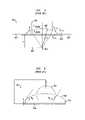
- FIG. 11shows the top view of an illustrative torpedo 1101 traveling in direction 1103 . If water is caused to penetrate area 1102 on the surface of torpedo 1101 , for example, the torpedo will turn in direction 1104 . Alternatively, if water is caused to penetrate the surface 1105 of torpedo 1101 , it will turn in direction 1106 .
- the torpedowill travel in direction 1103 , albeit at a slightly slower speed due to the friction experienced by the torpedo due to the penetration of the areas 1105 and 1102 .
- a forcesufficient to dislodge the fluid from the penetrated surface.
- Such a forcemay be, for example, a sonic or ultrasonic force applied to the penetrated areas 1105 and/or 1102 .
- other forcesmay be used to reverse this penetration with equal effectiveness.
Landscapes
- Engineering & Computer Science (AREA)
- Mechanical Engineering (AREA)
- Physics & Mathematics (AREA)
- Fluid Mechanics (AREA)
- Chemical & Material Sciences (AREA)
- Combustion & Propulsion (AREA)
- Ocean & Marine Engineering (AREA)
- General Engineering & Computer Science (AREA)
- Aviation & Aerospace Engineering (AREA)
- Physical Or Chemical Processes And Apparatus (AREA)
Abstract
Description
cos θ=(γS-V−γS-L)/γL-V Equation (1)
cos θ(V)=cos θ(V=0)+V2(∈0∈r)/(2dγL-V) Equation (4)
where cos θ(V=0) is the contact angle between the insulating
Claims (6)
Priority Applications (1)
| Application Number | Priority Date | Filing Date | Title |
|---|---|---|---|
| US10/649,285US7156032B2 (en) | 2003-08-22 | 2003-08-27 | Method and apparatus for controlling friction between a fluid and a body |
Applications Claiming Priority (2)
| Application Number | Priority Date | Filing Date | Title |
|---|---|---|---|
| US49726203P | 2003-08-22 | 2003-08-22 | |
| US10/649,285US7156032B2 (en) | 2003-08-22 | 2003-08-27 | Method and apparatus for controlling friction between a fluid and a body |
Publications (2)
| Publication Number | Publication Date |
|---|---|
| US20050039661A1 US20050039661A1 (en) | 2005-02-24 |
| US7156032B2true US7156032B2 (en) | 2007-01-02 |
Family
ID=34198259
Family Applications (1)
| Application Number | Title | Priority Date | Filing Date |
|---|---|---|---|
| US10/649,285Expired - Fee RelatedUS7156032B2 (en) | 2003-08-22 | 2003-08-27 | Method and apparatus for controlling friction between a fluid and a body |
Country Status (1)
| Country | Link |
|---|---|
| US (1) | US7156032B2 (en) |
Cited By (16)
| Publication number | Priority date | Publication date | Assignee | Title |
|---|---|---|---|---|
| US20070056853A1 (en)* | 2005-09-15 | 2007-03-15 | Lucnet Technologies Inc. | Micro-chemical mixing |
| US20070194178A1 (en)* | 2006-02-21 | 2007-08-23 | Amy Warncke Lang | Passive micro-roughness array for drag modification |
| US20070233668A1 (en)* | 2006-04-03 | 2007-10-04 | International Business Machines Corporation | Method, system, and computer program product for semantic annotation of data in a software system |
| US7357442B1 (en)* | 2004-12-06 | 2008-04-15 | Drews Hilbert F P | Post pressurizing material treatment for bodies moving through fluid |
| US20080236473A1 (en)* | 2006-09-11 | 2008-10-02 | Avinoam Kornblit | Method and apparatus for controlling friction between a fluid and a body |
| US20090295408A1 (en)* | 2004-09-30 | 2009-12-03 | Lucent Technologies Inc. | Nanostructured surface for microparticle analysis and manipulation |
| US20100108813A1 (en)* | 2007-03-30 | 2010-05-06 | Lang Amy W | passive drag modification system |
| US20100126372A1 (en)* | 2008-11-21 | 2010-05-27 | Lockheed Martin Corporation | Supercavitating Water-Entry Projectile |
| US20100237186A1 (en)* | 2009-03-23 | 2010-09-23 | Lockheed Martin Corporation | Drag-stabilized water-entry projectile and cartridge assembly |
| US20100247982A1 (en)* | 2003-11-18 | 2010-09-30 | Lucent Technologies Inc. | Reserve cell-array nanostructured battery |
| US8187894B2 (en) | 2003-09-30 | 2012-05-29 | Alcatel Lucent | Method and apparatus for controlling the flow resistance of a fluid on nanostructured or microstructured surfaces |
| US8800155B2 (en) | 2011-04-22 | 2014-08-12 | Jack A. Ekchian | Displacement sensor with reduced hysteresis |
| US9433907B2 (en) | 2003-03-31 | 2016-09-06 | Alcatel Lucent | Apparatus for controlling the movement of a liquid on a nanostructured or microstructure surface |
| US9681552B2 (en) | 2005-09-15 | 2017-06-13 | Alcatel Lucent | Fluid oscillations on structured surfaces |
| CN108454780A (en)* | 2018-04-24 | 2018-08-28 | 江苏科技大学 | A kind of adjustable damping device of surface parameter of imitative biological epidermis |
| CN111605690A (en)* | 2020-06-01 | 2020-09-01 | 大连理工大学 | A self-propelled unmanned light hull |
Families Citing this family (18)
| Publication number | Priority date | Publication date | Assignee | Title |
|---|---|---|---|---|
| JP4237610B2 (en)* | 2003-12-19 | 2009-03-11 | 株式会社東芝 | Maintenance support method and program |
| US7323033B2 (en)* | 2004-04-30 | 2008-01-29 | Lucent Technologies Inc. | Nanostructured surfaces having variable permeability |
| US7204298B2 (en) | 2004-11-24 | 2007-04-17 | Lucent Technologies Inc. | Techniques for microchannel cooling |
| US7666665B2 (en) | 2005-08-31 | 2010-02-23 | Alcatel-Lucent Usa Inc. | Low adsorption surface |
| US8287808B2 (en)* | 2005-09-15 | 2012-10-16 | Alcatel Lucent | Surface for reversible wetting-dewetting |
| US20070059213A1 (en)* | 2005-09-15 | 2007-03-15 | Lucent Technologies Inc. | Heat-induced transitions on a structured surface |
| US7412938B2 (en)* | 2005-09-15 | 2008-08-19 | Lucent Technologies Inc. | Structured surfaces with controlled flow resistance |
| US8084116B2 (en) | 2005-09-30 | 2011-12-27 | Alcatel Lucent | Surfaces physically transformable by environmental changes |
| KR100790866B1 (en)* | 2006-01-06 | 2008-01-03 | 삼성전자주식회사 | Black matrix for color filters and manufacturing method thereof |
| US7998431B2 (en)* | 2006-04-10 | 2011-08-16 | Alcatel Lucent | Environmentally sensitive nanostructured surfaces |
| US20070259156A1 (en)* | 2006-05-03 | 2007-11-08 | Lucent Technologies, Inc. | Hydrophobic surfaces and fabrication process |
| US7449649B2 (en)* | 2006-05-23 | 2008-11-11 | Lucent Technologies Inc. | Liquid switch |
| US7884530B2 (en)* | 2006-09-14 | 2011-02-08 | Alcatel-Lucent Usa Inc. | Reversible actuation in arrays of nanostructures |
| US8047235B2 (en)* | 2006-11-30 | 2011-11-01 | Alcatel Lucent | Fluid-permeable body having a superhydrophobic surface |
| IL181423A0 (en) | 2007-02-19 | 2008-01-06 | Waldhorn Joshua | Apparatus and method for improving movement of floating or under water marine vessels |
| US20140238646A1 (en)* | 2013-02-25 | 2014-08-28 | Alcatel-Lucent Ireland Ltd. | Sloped hierarchically-structured surface designs for enhanced condensation heat transfer |
| US9308987B1 (en) | 2014-05-15 | 2016-04-12 | The Curators Of The University Of Missouri | Drag reduction utilizing driven micro-cavities |
| GB2602354B (en)* | 2020-12-24 | 2024-10-02 | Thales Holdings Uk Plc | A barrier component and a method of manufacturing a barrier component |
Citations (25)
| Publication number | Priority date | Publication date | Assignee | Title |
|---|---|---|---|---|
| US1909186A (en)* | 1931-02-09 | 1933-05-16 | Lougheed Victor | Airplane wing |
| US2322632A (en)* | 1940-02-13 | 1943-06-22 | Jr William Harper | Covering for airfoil surfaces |
| US3510094A (en)* | 1967-12-11 | 1970-05-05 | James Clark | Method and means for reducing the skin friction of bodies moving in a fluid medium |
| US3554154A (en)* | 1969-02-26 | 1971-01-12 | Firestone Tire & Rubber Co | Structure with antifouling surface |
| US3957008A (en)* | 1974-03-28 | 1976-05-18 | Mccormick Michael E | Drag reduction of water vehicles using gas created by electrolysis on electrodes attached to the hull |
| US4429652A (en)* | 1981-11-23 | 1984-02-07 | Invocas, Inc. | Ultrasonic excitation of underwater torpedoes for enhancing maneuverability, speed and targeting accuracy |
| JPH05147572A (en)* | 1991-02-14 | 1993-06-15 | Japan Atom Energy Res Inst | Method to gradually reduce flow friction resistance |
| US5320309A (en)* | 1992-06-26 | 1994-06-14 | British Technology Group Usa, Inc. | Electromagnetic device and method for boundary layer control |
| US5359951A (en)* | 1993-02-11 | 1994-11-01 | The United States Of America As Represented By The Secretary Of The Navy | Active turbulence control using microelectrodes, permanent magnets in microgrooves |
| US5476056A (en)* | 1992-09-29 | 1995-12-19 | Mitsui Engineering & Shipbuilding Co., Ltd | Method of forming air layer over immersed surfaces of structure having immersed portions, and structure of coat layer formed over immersed surfaces |
| JPH08128413A (en)* | 1994-11-02 | 1996-05-21 | Teijin Ltd | Method for decreasing fluid resistance |
| US5791275A (en)* | 1996-06-14 | 1998-08-11 | The United States Of America As Represented By The Secretary Of The Navy | Surface layer comprising micro-fabricated tiles for electromagnetic control of fluid turbulence in sea water |
| DE19704207A1 (en) | 1997-02-05 | 1998-08-13 | Hermann Josef Wilhelm | Low drag hull |
| US5934622A (en)* | 1997-05-01 | 1999-08-10 | The United States Of America As Represented By The Secretary Of The Navy | Micro-electrode and magnet array for microturbulence control |
| US5941481A (en)* | 1997-07-07 | 1999-08-24 | The United States Of America As Represented By The Secretary Of The Navy | Device for interactive turbulence control in boundary layers |
| US5964433A (en)* | 1995-11-20 | 1999-10-12 | The Trustees Of Princeton Univ. | Staggered actuation of electromagnetic tiles for boundary layer control |
| US6059236A (en)* | 1998-06-19 | 2000-05-09 | General Atomics | Tangential force panel for active flow control of a conductive fluid |
| US6079345A (en)* | 1998-06-19 | 2000-06-27 | General Atomics | System and method for controlling the flow of a conductive fluid over a surface |
| US6185961B1 (en) | 1999-01-27 | 2001-02-13 | The United States Of America As Represented By The Secretary Of The Navy | Nanopost arrays and process for making same |
| JP2001114185A (en)* | 1999-10-19 | 2001-04-24 | Mitsubishi Heavy Ind Ltd | Sea water resistance reduced ship and resistance reducing method for hull |
| US6220549B1 (en)* | 1998-06-19 | 2001-04-24 | General Atomics | Method and apparatus for fabricating panels used for the active control of surface drag |
| JP2002266816A (en)* | 2001-03-07 | 2002-09-18 | Japan Atom Energy Res Inst | Turbulent frictional resistance reduced surface |
| US6520455B2 (en)* | 2000-02-16 | 2003-02-18 | Brown University Research Foundation | Method and apparatus for reducing turbulent drag |
| US20040069195A1 (en)* | 2002-04-26 | 2004-04-15 | Goldstein David B. | Methods for reducing the viscous drag on a surface and drag reducing device |
| WO2020081303A1 (en)* | 2018-10-19 | 2020-04-23 | Lam Research Corporation | In situ protective coating of chamber components for semiconductor processing |
- 2003
- 2003-08-27USUS10/649,285patent/US7156032B2/ennot_activeExpired - Fee Related
Patent Citations (25)
| Publication number | Priority date | Publication date | Assignee | Title |
|---|---|---|---|---|
| US1909186A (en)* | 1931-02-09 | 1933-05-16 | Lougheed Victor | Airplane wing |
| US2322632A (en)* | 1940-02-13 | 1943-06-22 | Jr William Harper | Covering for airfoil surfaces |
| US3510094A (en)* | 1967-12-11 | 1970-05-05 | James Clark | Method and means for reducing the skin friction of bodies moving in a fluid medium |
| US3554154A (en)* | 1969-02-26 | 1971-01-12 | Firestone Tire & Rubber Co | Structure with antifouling surface |
| US3957008A (en)* | 1974-03-28 | 1976-05-18 | Mccormick Michael E | Drag reduction of water vehicles using gas created by electrolysis on electrodes attached to the hull |
| US4429652A (en)* | 1981-11-23 | 1984-02-07 | Invocas, Inc. | Ultrasonic excitation of underwater torpedoes for enhancing maneuverability, speed and targeting accuracy |
| JPH05147572A (en)* | 1991-02-14 | 1993-06-15 | Japan Atom Energy Res Inst | Method to gradually reduce flow friction resistance |
| US5320309A (en)* | 1992-06-26 | 1994-06-14 | British Technology Group Usa, Inc. | Electromagnetic device and method for boundary layer control |
| US5476056A (en)* | 1992-09-29 | 1995-12-19 | Mitsui Engineering & Shipbuilding Co., Ltd | Method of forming air layer over immersed surfaces of structure having immersed portions, and structure of coat layer formed over immersed surfaces |
| US5359951A (en)* | 1993-02-11 | 1994-11-01 | The United States Of America As Represented By The Secretary Of The Navy | Active turbulence control using microelectrodes, permanent magnets in microgrooves |
| JPH08128413A (en)* | 1994-11-02 | 1996-05-21 | Teijin Ltd | Method for decreasing fluid resistance |
| US5964433A (en)* | 1995-11-20 | 1999-10-12 | The Trustees Of Princeton Univ. | Staggered actuation of electromagnetic tiles for boundary layer control |
| US5791275A (en)* | 1996-06-14 | 1998-08-11 | The United States Of America As Represented By The Secretary Of The Navy | Surface layer comprising micro-fabricated tiles for electromagnetic control of fluid turbulence in sea water |
| DE19704207A1 (en) | 1997-02-05 | 1998-08-13 | Hermann Josef Wilhelm | Low drag hull |
| US5934622A (en)* | 1997-05-01 | 1999-08-10 | The United States Of America As Represented By The Secretary Of The Navy | Micro-electrode and magnet array for microturbulence control |
| US5941481A (en)* | 1997-07-07 | 1999-08-24 | The United States Of America As Represented By The Secretary Of The Navy | Device for interactive turbulence control in boundary layers |
| US6059236A (en)* | 1998-06-19 | 2000-05-09 | General Atomics | Tangential force panel for active flow control of a conductive fluid |
| US6079345A (en)* | 1998-06-19 | 2000-06-27 | General Atomics | System and method for controlling the flow of a conductive fluid over a surface |
| US6220549B1 (en)* | 1998-06-19 | 2001-04-24 | General Atomics | Method and apparatus for fabricating panels used for the active control of surface drag |
| US6185961B1 (en) | 1999-01-27 | 2001-02-13 | The United States Of America As Represented By The Secretary Of The Navy | Nanopost arrays and process for making same |
| JP2001114185A (en)* | 1999-10-19 | 2001-04-24 | Mitsubishi Heavy Ind Ltd | Sea water resistance reduced ship and resistance reducing method for hull |
| US6520455B2 (en)* | 2000-02-16 | 2003-02-18 | Brown University Research Foundation | Method and apparatus for reducing turbulent drag |
| JP2002266816A (en)* | 2001-03-07 | 2002-09-18 | Japan Atom Energy Res Inst | Turbulent frictional resistance reduced surface |
| US20040069195A1 (en)* | 2002-04-26 | 2004-04-15 | Goldstein David B. | Methods for reducing the viscous drag on a surface and drag reducing device |
| WO2020081303A1 (en)* | 2018-10-19 | 2020-04-23 | Lam Research Corporation | In situ protective coating of chamber components for semiconductor processing |
Non-Patent Citations (11)
| Title |
|---|
| Kim, et al., "Nanostructured Surfaces for Dramatic Reduction of Flow Resistance in Droplet-Based Microfluidics," IEEE, pp. 479-482 (2002). |
| U.S. Appl. No. 10/403,159, filed Mar. 31, 2003, Kornblit et al. |
| U.S. Appl. No. 10/674,448, filed Sep. 30, 2003, Hodes et al. |
| U.S. Appl. No. 10/716,084, filed Nov. 18, 2003, Kroupenkine et al. |
| U.S. Appl. No. 10/798,064, filed Mar. 11, 2004, Arney et al. |
| U.S. Appl. No. 10/803,565, filed Mar. 18, 2004, Hodes et al. |
| U.S. Appl. No. 10/803,576, filed Mar. 18, 2004, Kroupenkine et al. |
| U.S. Appl. No. 10/803,641, filed Mar. 18, 2004, Hodes et al. |
| U.S. Appl. No. 10/806,543, filed Mar. 23, 2004, Arney et al. |
| U.S. Appl. No. 10/810,774, filed Mar. 26, 2004, Kroupenkine et al. |
| U.S. Appl. No. 10/816,569, filed Apr. 1, 2004, Gasparyan et al. |
Cited By (29)
| Publication number | Priority date | Publication date | Assignee | Title |
|---|---|---|---|---|
| US9433907B2 (en) | 2003-03-31 | 2016-09-06 | Alcatel Lucent | Apparatus for controlling the movement of a liquid on a nanostructured or microstructure surface |
| US8187894B2 (en) | 2003-09-30 | 2012-05-29 | Alcatel Lucent | Method and apparatus for controlling the flow resistance of a fluid on nanostructured or microstructured surfaces |
| US20100247982A1 (en)* | 2003-11-18 | 2010-09-30 | Lucent Technologies Inc. | Reserve cell-array nanostructured battery |
| US7833653B2 (en) | 2003-11-18 | 2010-11-16 | Alcatel-Lucent Usa Inc. | Reserve cell-array nanostructured battery |
| US20090295408A1 (en)* | 2004-09-30 | 2009-12-03 | Lucent Technologies Inc. | Nanostructured surface for microparticle analysis and manipulation |
| US7960167B2 (en) | 2004-09-30 | 2011-06-14 | Alcatel-Lucent Usa Inc. | Nanostructured surface for microparticle analysis and manipulation |
| US7357442B1 (en)* | 2004-12-06 | 2008-04-15 | Drews Hilbert F P | Post pressurizing material treatment for bodies moving through fluid |
| US9839908B2 (en) | 2005-09-15 | 2017-12-12 | Alcatel Lucent | Micro-chemical mixing |
| US9681552B2 (en) | 2005-09-15 | 2017-06-13 | Alcatel Lucent | Fluid oscillations on structured surfaces |
| US8734003B2 (en) | 2005-09-15 | 2014-05-27 | Alcatel Lucent | Micro-chemical mixing |
| US20070056853A1 (en)* | 2005-09-15 | 2007-03-15 | Lucnet Technologies Inc. | Micro-chemical mixing |
| US8113469B2 (en) | 2006-02-21 | 2012-02-14 | University Of Alabama | Passive micro-roughness array for drag modification |
| US20070194178A1 (en)* | 2006-02-21 | 2007-08-23 | Amy Warncke Lang | Passive micro-roughness array for drag modification |
| US20070233668A1 (en)* | 2006-04-03 | 2007-10-04 | International Business Machines Corporation | Method, system, and computer program product for semantic annotation of data in a software system |
| US20080236473A1 (en)* | 2006-09-11 | 2008-10-02 | Avinoam Kornblit | Method and apparatus for controlling friction between a fluid and a body |
| US7455021B2 (en)* | 2006-09-11 | 2008-11-25 | Lucent Technologies Inc. | Method and apparatus for controlling friction between a fluid and a body |
| US20100108813A1 (en)* | 2007-03-30 | 2010-05-06 | Lang Amy W | passive drag modification system |
| US8794574B2 (en) | 2007-03-30 | 2014-08-05 | The Board Of Trustees Of The University Of Alabama | Micro-array surface for passive drag modification |
| US7779759B2 (en) | 2008-11-21 | 2010-08-24 | Lockheed Martin Corporation | Supercavitating water-entry projectile |
| US20100126372A1 (en)* | 2008-11-21 | 2010-05-27 | Lockheed Martin Corporation | Supercavitating Water-Entry Projectile |
| US8222583B2 (en) | 2009-03-23 | 2012-07-17 | Lockheed Martin Corporation | Drag-stabilized water-entry projectile and cartridge assembly |
| US20100237186A1 (en)* | 2009-03-23 | 2010-09-23 | Lockheed Martin Corporation | Drag-stabilized water-entry projectile and cartridge assembly |
| US8800155B2 (en) | 2011-04-22 | 2014-08-12 | Jack A. Ekchian | Displacement sensor with reduced hysteresis |
| CN108454780A (en)* | 2018-04-24 | 2018-08-28 | 江苏科技大学 | A kind of adjustable damping device of surface parameter of imitative biological epidermis |
| CN108454780B (en)* | 2018-04-24 | 2019-09-27 | 江苏科技大学 | A drag reduction device with adjustable surface parameters of bionic skin |
| CN111605690A (en)* | 2020-06-01 | 2020-09-01 | 大连理工大学 | A self-propelled unmanned light hull |
| CN111605690B (en)* | 2020-06-01 | 2021-04-27 | 大连理工大学 | A self-propelled unmanned light hull |
| WO2021243747A1 (en)* | 2020-06-01 | 2021-12-09 | 大连理工大学 | Self-propelled unmanned lightship |
| JP2022531817A (en)* | 2020-06-01 | 2022-07-12 | 大連理工大学 | Self-propelled unmanned lightweight ship |
Also Published As
| Publication number | Publication date |
|---|---|
| US20050039661A1 (en) | 2005-02-24 |
Similar Documents
| Publication | Publication Date | Title |
|---|---|---|
| US7156032B2 (en) | Method and apparatus for controlling friction between a fluid and a body | |
| KR101190521B1 (en) | Method and apparatus for controlling the flow resistance of a fluid on nanostructured or microstructured surfaces | |
| JP5210417B2 (en) | Method and apparatus for controlling the movement of liquid on nanostructured or microstructured surfaces | |
| EP1591415B1 (en) | Nanostructured surfaces having variable permeability | |
| US7455021B2 (en) | Method and apparatus for controlling friction between a fluid and a body | |
| US8851103B2 (en) | Microfluidic valve systems and methods | |
| Edwards et al. | Dielectrowetting: The past, present and future | |
| Banerjee et al. | High-speed droplet actuation on single-plate electrode arrays | |
| KR20240017985A (en) | Microdroplet Manipulation Device | |
| Hong et al. | Frequency-dependent resonance and asymmetric droplet oscillation under ac electrowetting on coplanar electrodes | |
| KR20130117309A (en) | Bubble manipulation apparatus using ewod and micro-object manipulation method thereby | |
| JP4397642B2 (en) | Electrostatic suction type fluid discharge method and apparatus | |
| WO2005014179A1 (en) | Electrostatic suction type fluid discharge device, electrostatic suction type fluid discharge method, and plot pattern formation method using the same | |
| Garcí-Sánchez et al. | Fundamentals of electrowetting and applications in microsystems | |
| KR101353501B1 (en) | Separating device of particle | |
| KR101353508B1 (en) | Separating device of particle | |
| JP3967297B2 (en) | Electrostatic suction type fluid discharge method and apparatus | |
| Mohammed et al. | Effect of Direct Current Electrowetting on Dielectric on Droplet Impingement Dynamics | |
| KR20130037527A (en) | Device for varying wetting properties of droplet and separating device of particle using the same | |
| Zhu et al. | Directional manipulation of bubble behavior on wettability gradient surfaces: mechanisms, strategies, and applications | |
| Banerjee et al. | A new electrowetting lab-on-a-chip platform based on programmable and virtual wall-less channels | |
| Romero Herreros | Experimental study of the influence of an electric field on the shape of a droplet | |
| Garcıa-Sánchez et al. | Fundamentals of Electrowetting and Applications in Microsystems |
Legal Events
| Date | Code | Title | Description |
|---|---|---|---|
| FEPP | Fee payment procedure | Free format text:PAYOR NUMBER ASSIGNED (ORIGINAL EVENT CODE: ASPN); ENTITY STATUS OF PATENT OWNER: LARGE ENTITY | |
| AS | Assignment | Owner name:LUCENT TECHNOLOGIES INC., NEW JERSEY Free format text:ASSIGNMENT OF ASSIGNORS INTEREST;ASSIGNORS:KORNBLIT, AVINOAM;KRUPENKIN, THOMAS NIKITA;MANDICH, MARY LOUISE;AND OTHERS;REEL/FRAME:019995/0675;SIGNING DATES FROM 20031217 TO 20071018 | |
| FPAY | Fee payment | Year of fee payment:4 | |
| AS | Assignment | Owner name:CREDIT SUISSE AG, NEW YORK Free format text:SECURITY INTEREST;ASSIGNOR:ALCATEL-LUCENT USA INC.;REEL/FRAME:030510/0627 Effective date:20130130 | |
| AS | Assignment | Owner name:ALCATEL-LUCENT USA INC., NEW JERSEY Free format text:MERGER;ASSIGNOR:LUCENT TECHNOLOGIES INC.;REEL/FRAME:032891/0562 Effective date:20081101 | |
| FPAY | Fee payment | Year of fee payment:8 | |
| AS | Assignment | Owner name:ALCATEL-LUCENT USA INC., NEW JERSEY Free format text:RELEASE BY SECURED PARTY;ASSIGNOR:CREDIT SUISSE AG;REEL/FRAME:033950/0261 Effective date:20140819 | |
| AS | Assignment | Owner name:OMEGA CREDIT OPPORTUNITIES MASTER FUND, LP, NEW YORK Free format text:SECURITY INTEREST;ASSIGNOR:WSOU INVESTMENTS, LLC;REEL/FRAME:043966/0574 Effective date:20170822 Owner name:OMEGA CREDIT OPPORTUNITIES MASTER FUND, LP, NEW YO Free format text:SECURITY INTEREST;ASSIGNOR:WSOU INVESTMENTS, LLC;REEL/FRAME:043966/0574 Effective date:20170822 | |
| AS | Assignment | Owner name:WSOU INVESTMENTS, LLC, CALIFORNIA Free format text:ASSIGNMENT OF ASSIGNORS INTEREST;ASSIGNOR:ALCATEL LUCENT;REEL/FRAME:044000/0053 Effective date:20170722 | |
| FEPP | Fee payment procedure | Free format text:MAINTENANCE FEE REMINDER MAILED (ORIGINAL EVENT CODE: REM.) | |
| LAPS | Lapse for failure to pay maintenance fees | Free format text:PATENT EXPIRED FOR FAILURE TO PAY MAINTENANCE FEES (ORIGINAL EVENT CODE: EXP.); ENTITY STATUS OF PATENT OWNER: LARGE ENTITY | |
| STCH | Information on status: patent discontinuation | Free format text:PATENT EXPIRED DUE TO NONPAYMENT OF MAINTENANCE FEES UNDER 37 CFR 1.362 | |
| FP | Lapsed due to failure to pay maintenance fee | Effective date:20190102 | |
| AS | Assignment | Owner name:WSOU INVESTMENTS, LLC, CALIFORNIA Free format text:RELEASE BY SECURED PARTY;ASSIGNOR:OCO OPPORTUNITIES MASTER FUND, L.P. (F/K/A OMEGA CREDIT OPPORTUNITIES MASTER FUND LP;REEL/FRAME:049246/0405 Effective date:20190516 | |
| AS | Assignment | Owner name:OT WSOU TERRIER HOLDINGS, LLC, CALIFORNIA Free format text:SECURITY INTEREST;ASSIGNOR:WSOU INVESTMENTS, LLC;REEL/FRAME:056990/0081 Effective date:20210528 |