US7155746B2 - Anti-wicking protective workwear and methods of making and using same - Google Patents
Anti-wicking protective workwear and methods of making and using sameDownload PDFInfo
- Publication number
- US7155746B2 US7155746B2US10/330,514US33051402AUS7155746B2US 7155746 B2US7155746 B2US 7155746B2US 33051402 AUS33051402 AUS 33051402AUS 7155746 B2US7155746 B2US 7155746B2
- Authority
- US
- United States
- Prior art keywords
- outerwear
- surface tension
- outside surface
- protective
- low surface
- Prior art date
- Legal status (The legal status is an assumption and is not a legal conclusion. Google has not performed a legal analysis and makes no representation as to the accuracy of the status listed.)
- Expired - Lifetime, expires
Links
Images


Classifications
- A—HUMAN NECESSITIES
- A41—WEARING APPAREL
- A41D—OUTERWEAR; PROTECTIVE GARMENTS; ACCESSORIES
- A41D19/00—Gloves
- A41D19/0055—Plastic or rubber gloves
- A41D19/0082—Details
- A41D19/0089—Joints between glove and cuff or garment
- A—HUMAN NECESSITIES
- A41—WEARING APPAREL
- A41D—OUTERWEAR; PROTECTIVE GARMENTS; ACCESSORIES
- A41D13/00—Professional, industrial or sporting protective garments, e.g. surgeons' gowns or garments protecting against blows or punches
- A41D13/12—Surgeons' or patients' gowns or dresses
- A41D13/1209—Surgeons' gowns or dresses
- A—HUMAN NECESSITIES
- A41—WEARING APPAREL
- A41D—OUTERWEAR; PROTECTIVE GARMENTS; ACCESSORIES
- A41D27/00—Details of garments or of their making
- A41D27/10—Sleeves; Armholes
- A—HUMAN NECESSITIES
- A41—WEARING APPAREL
- A41D—OUTERWEAR; PROTECTIVE GARMENTS; ACCESSORIES
- A41D27/00—Details of garments or of their making
- A41D27/24—Hems; Seams
- A41D27/245—Hems; Seams made by welding or gluing
- A—HUMAN NECESSITIES
- A61—MEDICAL OR VETERINARY SCIENCE; HYGIENE
- A61B—DIAGNOSIS; SURGERY; IDENTIFICATION
- A61B42/00—Surgical gloves; Finger-stalls specially adapted for surgery; Devices for handling or treatment thereof
- A—HUMAN NECESSITIES
- A61—MEDICAL OR VETERINARY SCIENCE; HYGIENE
- A61B—DIAGNOSIS; SURGERY; IDENTIFICATION
- A61B46/00—Surgical drapes
- A—HUMAN NECESSITIES
- A61—MEDICAL OR VETERINARY SCIENCE; HYGIENE
- A61B—DIAGNOSIS; SURGERY; IDENTIFICATION
- A61B46/00—Surgical drapes
- A61B46/40—Drape material, e.g. laminates; Manufacture thereof
Definitions
- the present inventionpertains to protective workwear. More specifically, the present invention pertains to medical gowns, surgical gowns and other protective workwear that offer additional contamination protection to users of such workwear, and methods of making and using the same.
- medical service provideris meant to encompass all persons who treat either human or animal patients through the course of their employment or otherwise, or are exposed to blood or other types of low surface tension liquids containing potentially harmful components or contaminants, during the course of their employment or otherwise.
- autoimmune deficiency syndromeHIV virus
- other blood borne pathogenssuch as hepatitis
- protective workwear used in medical procedureshave been made from nonwoven materials instead of traditional woven materials, such as cotton and linen-based fabrics.
- cloth-like multi-layered fibrous nonwoven laminates, films or film laminates, and film and fibrous nonwoven laminate compositeshave been produced that offer barrier protection when employed as medical garment material.
- Such materialshave proven in some circumstances, to be liquid-impervious, but breathable.
- such garment materialsare made from only fibrous nonwoven materials and/or breathable films, such materials have allowed the passage of gasses/vapors in order to provide the necessary thermal comfort to medical personnel, but without sacrificing high levels of protection.
- Such garmentsare made from monolithic films (without pores) or film composites, such garments may often be uncomfortable to wear for an extended period as they restrict the ability of air to easily pass through them.
- such materialsare likewise uncomfortable to wear. For instance, it is known to coat large portions of hospital or surgeon's garments in the arm and abdominal areas. While such garments may provide high barriers to liquids that may be present in a hospital setting, such garments are often uncomfortable since they fail to breathe in these same large protected areas. Further, if large areas of such garments are coated with a liquid barrier, such film coating may fail to provide the necessary coefficient of friction which is required for the sustained placement of a glove over such materials, as is the practice in a hospital or operating room in which gloves are placed over the sleeves of a surgeon or other medical practitioner.
- the term “outside surface”shall mean the surface of protective workwear facing away from a person wearing such workwear.
- the term “inside surface”shall mean the surface of protective workwear facing the body of the person wearing the protective workwear, i.e. closest to the skin of the person.
- the terms “protective workwear” and “protective outerwear”shall be used synonymously.
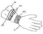
- a porcelain model of a medical provider's hand 10has been donned with one surgical glove 20 (easily seen by the rolled up glove edge ridge or “beaded” edge).
- an exemplary sleeve of a medical gown 30has been placed over the model's wrist, and lower arm area, with the sleeve including a cuff 32 .
- the glovehas then been placed over the model, and in an overlapping fashion, over the cuffed lower sleeve portion of the garment.
- Liquid 34(in this case, 20% isopropyl alcohol and water with red food coloring for ease of visualization, (all with surface tension of approximately 32 dynes/cm, as a preliminary model for fluids that a medical provider may contact in a surgical theater) is shown to have wicked along the outside surface of the nonwoven garment, along the inside surface of the glove and up the inside surface of the nonwoven garment. Subsequently, the arm mold 10 became wet at various locations.
- Drop on demand, continuous, valvejet and other forms of ink jet printing apparatushave been used for a period of time to apply inks to a variety of substrates.
- a drop on demand ink jet printing apparatusoperates to discharge individual droplets of ink onto a substrate in a predetermined pattern to be printed.
- Ink jet printingis a non-impact and non-contact printing method in which an electronic signal controls and directs the droplets or stream of ink that can be deposited on a wide variety of substrates.
- Current ink jet printing technologyinvolves forcing the ink drops through small nozzles by piezoelectric pressure, thermal ejection, or oscillation, and onto the surface of a material/medium.
- Ink jet printingis extremely versatile in terms of the variety of substrates that can be treated, as well as the print quality and the speed of operation that can be achieved.
- ink jet printingis digitally controllable.
- ink jet methodologyhas been widely adopted for industrial marking and labeling.
- ink jet printing methodologyhas also found widespread use in architectural and engineering design applications, medical imaging, office printing (of both text and graphics), geographical imaging systems (e.g., for seismic data analysis and mapping), signage, in display graphics (e.g., photographic reproduction, business and courtroom graphics, graphic arts), and the like.
- ink jet printinghas now also been used to create an image on a variety of textile and nonwoven substrates.
- phase change materialssuch as hot melt wax inks
- Protective outerwear for covering a body portionincludes an inside surface and an outside surface.
- the outside surfaceincludes thereupon a printed blocking material in a continuous unbroken band, region, or combination of such, for blocking the wicking of low surface tension liquids at least on the outside surface of the outerwear.
- the protective outerwearincludes low surface tension liquid blocking material on the outside surface in multiple bands. In still a further alternative embodiment the protective outerwear includes low surface tension liquid blocking material on the outside surface in a region. In still a further alternative embodiment, the protective outerwear includes low surface tension liquid blocking material on the outside surface in at least a band and a region. In still a further alternative embodiment the protective outerwear includes low surface tension liquid blocking material on the outside surface in a band having a width between about 1 ⁇ 8 inch to 1 inch. In still a further alternative embodiment, the protective outerwear includes low surface tension liquid blocking material on the outside surface in a band having a width between about 1 ⁇ 8 inch to 1 ⁇ 2 inch.
- a protective outerwear garment having an inside surface and an outside surfaceincludes a body portion; a neck portion; two sleeves attached to the body, each sleeve having an inside surface and an outside surface, each sleeve including a lower edge for encircling a user's wrist and hand, an elbow region for containing a user's elbow, and an upper edge attached to the body portion.
- the sleevesinclude at least along their outside surfaces a printed blocking material in a continuous unbroken band, region, or combination of such, for blocking the wicking of low surface tension liquids on at least the outside surface of the outerwear.
- FIG. 1illustrates a photographic image of a nonwoven fabric sleeve over a hand model and including a glove positioned over the model and sleeve edge.
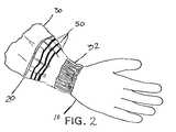
- FIG. 2illustrates a perspective view of an alternate embodiment of a nonwoven sleeve in accordance with the invention which includes multiple continuous colored bands of low surface tension liquid blocking material deposited along a sleeve surface.
- FIG. 3illustrates a perspective view of an alternate embodiment of a nonwoven sleeve in accordance with the invention which includes a continuous colored area of low surface tension liquid blocking material deposited along a sleeve surface.
- FIG. 4illustrates a perspective view of an alternate embodiment of a nonwoven sleeve in accordance with the invention which includes a combination of a continuous colored area of low surface tension liquid blocking material deposited along a sleeve surface and a continuous colored band of low surface tension liquid blocking material deposited along a sleeve surface.
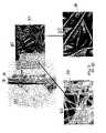
- FIGS. 5A–5Dillustrate photographic images of ink jet treated nonwoven fabric in accordance with the present invention.
- FIG. 6illustrates an exemplary protective garment in accordance with the invention, namely a surgeon's gown.
- FIG. 7illustrates another exemplary protective garment in accordance with the invention, namely medical scrubs.
- FIG. 8is a schematic view of a drop on demand (piezo) ink jet printing system for printing on protective outerwear apparel.
- FIG. 9is a schematic view of a continuous ink jet printing system for printing on protective outerwear apparel.
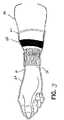
- FIGS. 10A–10Cillustrate a photographic image of an alternate embodiment of a nonwoven sleeve constructed in accordance with the present invention in which a lower end of the sleeve has been turned upward, and in which a plurality of continuous ultrasonic bonded bands, the bands having a pattern, are positioned circumferentially about a sleeve surface.
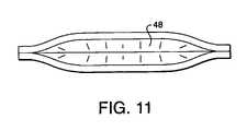
- FIG. 11is a sectional view of FIG. 10A taken along lines 38 .
- fabricrefers to all woven, knitted and nonwoven fibrous webs, unless one type is specified.
- the term “layer” when used in the singularcan have the dual meaning of a single element or a plurality of elements.
- meltblown fibersmeans fibers formed by extruding a molten thermoplastic material through a plurality of fine, usually circular, die capillaries as molten threads or filaments into converging high velocity, usually hot, gas (e.g. air) streams which attenuate the filaments of molten thermoplastic material to reduce their diameter, which may be to microfiber diameter. Thereafter, the meltblown fibers are carried by the high velocity gas stream and are deposited on a collecting surface to form a web of randomly dispersed meltblown fibers.
- gase.g. air
- multi-layer laminatemeans a laminate wherein some of the layers are spunbond and some meltblown such as a spunbond/meltblown/spunbond (SMS) laminate and others as disclosed in U.S. Pat. No. 4,041,203 to Brock et al., U.S. Pat. No. 5,169,706 to Collier, et al., U.S. Pat. No. 5,145,727 to Potts et al., U.S. Pat. No. 5,178,931 to Perkins et al. and U.S. Pat. No. 5,188,885 to Timmons et al. each of which is incorporated by reference herein in its entirety.
- SMSspunbond/meltblown/spunbond
- Such a laminatemay be made by sequentially depositing onto a moving forming belt first a spunbond fabric layer, then a meltblown fabric layer and last another spunbond layer and then bonding the laminate in a manner described below.
- the fabric layersmay be made individually, collected in rolls, and combined in a separate bonding step.
- Such fabricsusually have a basis weight of from about 0.1 to 12 osy (6 to 400 gsm), or more particularly from about 0.75 to about 3 osy.
- Multi-layer laminatesmay also have various numbers of meltblown (M) layers or multiple spunbond (S) layers in many different configurations and may include other materials like films (F) or coform materials, e.g. SMMS, SM, SFS, SMS etc.
- phase-changerefers to a material which is processed at elevated temperatures in a liquid, substantially liquid or semi-solid state and then solidifies or returns to its natural state when cooled.
- the material or compositionis desirably at least partially hydrophobic.
- the phase change liquidmay be, for example, a wax, petrolatum based lotion, adhesive, thermoplastic, and so forth.
- the term “petrolatum”refers to a semi-solid mixture of hydrocarbons obtained from petroleum, such as Glenpure L white petrolatum available from Glen Corporation of St. Paul, Minn.
- waxshall mean a low-melting organic mixture or compound, which is thermoplastic but solid at room temperature and generally similar in composition to fats and oils.
- the termcan include hydrocarbons, esters of fatty acids, and alcohols. Such materials are typically hydrophobic.
- bondedand “bonding” refer to the joining, adhering, connecting, attaching, or the like of two elements. Two elements will be considered to be bonded together when they are bonded directly to one another or indirectly to one another, such as when each is directly bonded to intermediate elements. Such bonding may occur for example, by adhesive, thermal or ultrasonic methods.
- thermal point bondinginvolves passing a fabric or web of fibers to be bonded between a heated calender roll and an anvil roll.
- the calender rollis usually, though not always, patterned in some way so that the entire fabric is not bonded across its entire surface, and the anvil roll is usually flat.
- various patterns for calender rollshave been developed for functional as well as aesthetic reasons.
- One example of a patternhas points and is the Hansen Pennings or “H&P” pattern with about a 30% bond area with about 200 bonds/square inch as taught in U.S. Pat. No. 3,855,046 to Hansen and Pennings, incorporated herein by reference in its entirety.
- the H&P patternhas square point or pin bonding areas wherein each pin has a side dimension of 0.038 inches (0.965 mm), a spacing of 0.070 inches (1.778 mm) between pins, and a depth of bonding of 0.023 inches (0.584 mm).
- the resulting patternhas a bonded area of about 29.5%.
- Another typical point bonding patternis the expanded Hansen Pennings or “EHP” bond pattern which produces a 15% bond area with a square pin having a side dimension of 0.037 inches (0.94 mm), a pin spacing of 0.097 inches (2.464 mm) and a depth of 0.039 inches (0.991 mm).
- Another typical point bonding pattern designated “714”has square pin bonding areas wherein each pin has a side dimension of 0.023 inches, a spacing of 0.062 inches (1.575 mm) between pins, and a depth of bonding of 0.033 inches (0.838 mm). The resulting pattern has a bonded area of about 15%.
- Yet another common patternis the C-Star pattern which has a bond area of about 16.9%.
- the C-Star patternhas a cross-directional bar or “corduroy” design interrupted by shooting stars.
- Other common patternsinclude a diamond pattern with repeating and slightly offset diamonds with about a 16% bond area and a wire weave pattern looking as the name suggests, e.g. like a window screen, with about a 19% bond area.
- the percent bonding areavaries from around 10% to around 30% of the area of the fabric laminate web.
- the spot bondingholds the laminate layers together as well as imparts integrity to each individual layer by bonding filaments and/or fibers within each layer.
- the term “ultrasonic bonding” or “ultrasonic welding”means a process performed, for example, by passing a fabric, such as a nonwoven material, between a sonic horn and anvil roll as illustrated in U.S. Pat. No. 4,374,888 to Bornslaeger, incorporated by reference herein in its entirety.
- a fabricsuch as a nonwoven material
- the fabric(s)is/are respectively, heated to a melting point, such that all pores, capillaries, and so forth, if any, in the material collapse and/or are sealed in the melting process. The integrity and continuity of the material is maintained (i.e., the material does not become too thin or perforated in the bonded areas).
- nonwovenand “nonwoven fabric” mean either a nonwoven web, scrim, netting, film, a foam sheet material, or a combination thereof.
- fibrous nonwovenand “fibrous nonwoven fabric or web” mean a web having a structure of individual fibers, filaments or threads which are interlaid, but not in an identifiable manner as in a knitted fabric. Fibrous nonwoven fabrics or webs have been formed from many processes such as for example, meltblowing processes, spunbonding processes, and bonded carded web processes. The basis weight of fibrous nonwoven fabrics is usually expressed in ounces of material per square yard (osy) or grams per square meter (gsm) and the fiber diameters useful are usually expressed in microns. (Note that to convert from osy to gsm, multiply osy by 33.91).
- protective workwearshall encompass medical garments or medical workwear and other forms of protective attire used by various industries/pro professions to protect workers from contaminants or to prevent the contamination of others.
- protective workwearincludes but is not limited to hospital and surgical gowns, medical scrubs, medical drapes, coveralls, overalls, face masks, and garments used to protect either a portion of, or an entire body.
- garment(s) and “apparel”are used synonymously.
- spunbonded fibersrefers to small diameter fibers which are formed by extruding molten thermoplastic material as filaments from a plurality of fine, usually circular capillaries of a spinneret with the diameter of the extruded filaments then being rapidly reduced as by, for example, in U.S. Pat. No. 4,340,563 to Appel et al., U.S. Pat. No. 3,692,618 to Dorschner et al., U.S. Pat. No. 3,802,817 to Matsuki et al., U.S. Pat. Nos. 3,338,992 and 3,341,394 to Kinney, U.S. Pat. No.
- Spunbond fibersare generally not tacky when they are deposited onto a collecting surface. Spunbond fibers are generally continuous and often have average diameters (from a sample of at least 10) larger than 7 microns, more particularly, between about 10 and 20 microns.
- low surface tension liquidshall mean liquids that demonstrate a surface tension of between about 25 and 50 dynes/cm, but typically between about 30 and 45 dynes/cm. Surface tension may be measured in accordance with standard Wilhemy plate or tensiometer methods. Such low surface tension liquids include, but are not limited to scrub solutions, blood, isopropyl alcohol and other liquids that are commonly encountered during a medical procedure or in a medical environment.
- hydrophobicshall generally refer a nonwoven fabric that possesses a surface that does not promote the spreading of water.
- the waterinstead, forms drops and a contact angle that can be measured from the plane of the fiber/material surface, tangent to the water surface at the three-phase boundary line (air-water-fiber).
- the contact angleis often greater than 90 degrees.
- Hydrophobic fabricsmay be produced from materials that are inherently hydrophobic or from hydrophilic fibers/films that have been treated in some fashion to be hydrophobic. Such treatment may include chemical treatments.
- low surface tension liquid blocking materialis a substance that can be applied to a nonwoven material that will block the travel path of wicking low surface tension liquids. Such term shall include but not be limited to wax inclusive inks. It is used interchangeably with the term “circumambient material”.
- wickshall mean to carry moisture/liquid away, typically by capillary action. Such term also encompasses the ability of a liquid to travel between sheet materials, such as between the surface of a fibrous nonwoven sheet material such as a surgical drape and a film sheet, such as a glove.
- inkshall mean any material, liquid or fluid that can be printed, or jetted from an ink jet printer.
- Inksshall include phase change liquids. Inks may be colored or uncolored.
- colorantshall mean containing a colorant or a coloring agent which is visually perceptible to the human eye.
- colorantmay include pigments or dyes.
- uncoloredshall mean not containing a colorant or coloring agent which is visually perceptible to the human eye.
- contaminantshall mean a chemical agent or biological organism/pathogen that can potentially harm a human being or animal.
- a structurehas been developed to reduce the likelihood that low surface tension liquid such as blood will wick along the outside surfaces of a nonwoven material, and further, to reduce the likelihood that low surface tension liquids will wick between the outside surfaces of nonwoven materials of protective workwear and the inside surface of other coverings, such as gloves or boots/shoe covers worn over such workwear, so as to avoid the liquid traveling around or past the edges of such workwear to exposed areas of human skin.
- such a structurewill reduce the likelihood that blood will wick along the outside surface of surgical gowns and along the inside surface of gloves or foot coverings worn over such gowns.
- Such a structureincludes a nonwoven garment that has been treated to include a continuous line, band or path of low surface tension liquid blocking material deposited at least along an outside surface portion of a sleeve, leg, waist, or neck opening of such body garment.
- line, band, or pathmay be placed on a garment that goes on/or around the body extremities, such as on an ankle portion of a boot, hood portion of protective outerwear, side edges of facemasks, or wrist portions of hand coverings.
- Such blocking materialis desirably situated adjacent the opening of such a garment. In the case of a sleeve, such blocking material is desirably at a location over which a glove will be placed during usage.
- such blocking materialis desirably at a location over which a booty or shoe cover will be placed during usage.
- such blocking materialis desirably placed adjacent the waist portion (above the shirt tail), desirably above that portion of the garment that would be tucked in such that the continuous line of blocking material would not be gathered so as to break the continuity of the line or create overlapping of the fabric.
- such blocking materialis desirably deposited below the gathered waist portion. If such blocking area would be gathered or overlapped it is possible that the continuous line of blocking material would be broken. In the unbroken state, such blocking treatment will act as a dam or gutter to prevent such low surface tension liquid from approaching the edges of a garment that surround a wearer's body part.
- such structureincludes a nonwoven garment that has been treated to include a continuous region or area of low surface tension liquid blocking material deposited along at least an outer surface portion of a sleeve, leg, waist, or neck portion of such a garment.
- a regionis visually more than a printed line, and can be described as a generally wider area of blocking material application.
- such a low surface tension liquid blocking materialis placed in sufficiently wide a region/area to provide a continuous region that blocks the wicking of low surface tension liquids.
- such regiondoes not encompass an entire arm, leg, neck or waist area, as such would potentially interfere with the comfort of the garment containing the treatment, and would unnecessarily add to the cost of such garments.
- treatedand “treatment” is meant, exposed to, and brought in contact with a low surface tension liquid blocking material substance via one of numerous methods including but not limited to, application methods such as spraying, printing, dipping, or extruding.
- application methodssuch as spraying, printing, dipping, or extruding.
- Such continuous lines, bands, paths or region/areas (or combination thereof)are desirably in the form of a line or ribbon of low surface tension liquid blocking material which circumscribes the outer surface of the sleeve, leg, waist, or neck portion of a garment.
- Such, line, band, path or region/areamay comprise one or more linear or nonlinear bands, which sufficiently seal and/or block the pores, if any, of the garment in the treated line or region, at least along the outside surface of the garment, but desirably through the entire thickness of one or more of the layers of the garment.
- Such treated areasmay include areas of continuous patterns and also include in some embodiments, discontinuous patterns, lines, bands or regions in addition to the continuous patterns, lines, bands or regions.
- such treated lines, bands or areas on the workwearare immediately adjacent an untreated line, band or area, so as to provide contact areas of varying coefficients of friction, should a glove or shoe cover be placed over such workwear areas.
- the glove or shoe coveris less likely to slide during use, as the varying coefficients of friction provide degrees of traction to maintain the glove/shoe cover or other covering in position.
- Such treatment of circumambient materialis desirable situated on each arm, between the cuff region and the elbow region of a gown.
- a medical gowndesirably includes a body covering portion and sleeves extending from the body portion that end in sleeve ends or in cuffs.
- Such circumambient materialis desirably equidistant from the cuff or sleeve/leg/waist edge of the protective workwear (that is the edge of the garment opening surround the limb), but is not required to be so situated.
- circumambient materialdesirably penetrates/and blocks the pores of a nonwoven garment (if any) so as to create a barrier line through the entire thickness of the garment, thereby functioning as a gutter to collect/stop or dam the low surface tension liquid from proceeding past the circumambient material and into the cuff or sleeve edge region, or ankle region as the case may be.
- the gownis of a multiple layered fabric with a barrier layer between an inside surface and an outside surface, it is desirable in one embodiment to have the treatment penetrate the thickness of the outside surface layer.
- such circumambient materialmay be deposited in a nonuniform thickness application, such that a thicker, heavier deposit could be placed in areas of high contact, or wider areas of circumambient material can be placed in such locations.
- circumambient materialmay be deposited in a continuous straight line or path around the garment, it is not necessary that such be the case.
- such materialmay be deposited in a loop pattern or some other regular or irregular pattern around the garment circumference, so long as it is continuous, without any breaks or gaps.
- an artistic patternmay be employed in order to make the garment more aesthetically pleasing or to improve brand name recognition.
- such low surface tension liquid blocking materialdesirably is positioned at a location on a sleeve that will be covered by a glove, when a glove is positioned over such sleeve during the medical service provider's preparatory dressing.
- a gown treated in such a fashionprovides for a gutter to block the spread of wicking liquid, but also allows for the frictional contact of the gown sleeve and a glove, thereby allowing the glove to remain securely positioned over the gown.
- circumambient materialis cost efficient, thereby leading to a lower cost garments.
- FIG. 2an embodiment of such a treated garment is illustrated.
- a series of colored bands 50surround the garment sleeve, thereby creating a multiple stepped barrier to low surface tension liquids.
- An untreated area on the garmentis situated between each of the bands. While the bands are shown as seen through the glove 20 , it is not necessary that they be so.
- FIG. 3a further alternate embodiment of the treated garment of FIG. 2 is illustrated.
- a colored continuous region/area 60surrounds the garment sleeve and is adjacent untreated areas. This region is also shown as visible through the glove 20 .
- FIG. 4still a further alternate embodiment of the treated garment of FIG. 2 is illustrated.
- a colored continuous area 60surrounds the garment sleeve. This continuous area is adjacent a single band of colored material 61 , with the continuous area and single band each creating a barrier to low surface tension liquids, and separated by an untreated area. As in the previous figures, the region and band are both shown as visible through the glove 20 .
- Such low surface tension liquid blocking material lines, bands or pathsare each desirably between about 1 ⁇ 8 to about 1 inch in width and are positioned in a continuous generally linear path around the circumference of the sleeve, leg, waist, or neck opening, desirably equidistant from the garment opening. More desirably, such blocking material, lines, bands, or paths have a width between about 3/16 and about 1 ⁇ 2 inch. If a low surface tension liquid blocking material is present either by itself, or in conjunction with additional blocking aids (such as bonds which are described below), it is desirable that such additional blocking aids have a width of between about 1 ⁇ 4 and 1 ⁇ 2 inch in width.
- the term “continuous region”shall be used to describe an area of the workwear having a low surface tension liquid blocking material deposited thereon having at least 1 ⁇ 8 inch width.
- the terms “line(s)”, “path(s)”, “band(s)” and/or “pattern(s)”,shall refer to a continuous region around the garment sleeve, leg or opening, that is less than 1 inch width.
- a bandis present on a sleeve of a gown approximately between about 1 ⁇ 2 inch and about 6 inches from the edge of the gown cuff or sleeve edge surrounding the wrist of the user.
- the garmentmay include in addition to the previously described low surface tension liquid blocking material deposits, outwardly turned up edge portions at the edge of the sleeve, leg, pant, waist or other garment portion edge/margin (surrounding the body portion) so as to create a further dam-like/pocket structure.
- such treated garmentmay include additional barrier aids, such as thermal or ultrasonic bonds along the garment edge portions, to further seal the garment from wicking fluids.
- the garmentwould be bonded sufficiently to close/seal any pores in at least an outer layer, but not so bonded as to create perforations, or weaknesses in the garment structure.
- a garment that has been so treatedmay include traditional cuffs that have been added to edges of the sleeves, or cuff-like structures that have been added to the edges of the legs, waist or neck portions and that have been further treated in some fashion so as to repel certain liquids.
- FIGS. 10A–10Caspects of these alternate embodiments are illustrated.
- upturned sleeve edges and bonded portionsare photographically illustrated.
- the garmentmay include in addition to the previously described treatments, outwardly upturned end sleeve portions 27 on the edge of the sleeve 30 with ultrasonic bonded barriers 38 and may also include, by way of non-limiting example, a leg edge, a neck edge and/or a waist edge that have been hemmed ultrasonically (not shown).
- Such upturned portionsprovide yet another structural barrier to the spread of wicking low surface tension liquids.
- a cuff, of the type previously described hereincould then be attached to the sleeve at the hemmed area or sleeve edge.
- a single ultrasonically bonded barrier 38 in the form of a patterned bandsurrounds an upturned garment sleeve.
- the patterned bandprovides both a low surface tension liquid blocking functionality (since it closed the pores on the outside surface) as well as a bond between the layers of the garment sleeve 30 , if any.
- This band or pattern 38provides both a gutter and a holding area or pocket (illustrated as 48 in FIG. 11 ) for retaining low surface tension liquid.
- FIG. 10Ban alternative embodiment similar to that shown in 10 A is illustrated, except that the patterned band 38 has a different pattern.
- FIG. 10Can alternative embodiment of the treated garment sleeve 30 is also illustrated.
- a pair of bonded continuous bands 38which surround an upturned garment sleeve 30 are illustrated.
- the pair of bands 38provides both low surface tension liquid blocking functionality as well as a pair of bonds between the layers of the garment sleeve 30 .
- the bandsprovide gutters and pockets ( 48 in FIG. 11 ) for retaining low surface tension liquid to be contained on an outer surface on either side of the bands.
- FIG. 11is a sectional view of FIG. 10A taken along line 38 , illustrating a pocket 48 which is formed when one or more layers of the garment sleeve 30 are thermally or ultrasonically bonded to each other to provide one or more continuous bands, namely, but not by way of limitation, lines, paths, patterns, regions, and so forth of low surface tension liquid blocking functionality but not depending on material deposition, as is illustrated generally in FIGS. 10A–10C .
- Such bondingmay be accomplished via a vibrational ultrasonic sewing machine. Vibrational ultrasonic sewing machines are commercially available, and one such ultrasonic sewing machine, Model LM 1220 manufactured by Sonobond Ultrasonics, West Chester, Pa., was used to create the bond patterns illustrated in FIGS. 10A–10C .
- the useful range of frequenciesis very wide. Frequencies of up to about 40 kHz and about 20 kHz are often used commercially. However, frequencies of, for example, 18 kHz and as low as 10 kHz have also been used in some applications.
- the power settings used commerciallyare often in a range of 10 Watts to 1000 Watts, although other power settings may be utilized. Desirably, the power settings are in a range of about 50 Watts to about 900 Watts; more desirably, the power settings are in a range of about 100 Watts to about 500 Watts.
- the pressure settings for both the ultrasonic horn and the pattern wheelare set in a range of about 1 psi to about 100 psi. More desirably, the pressure settings for both the ultrasonic horn and the pattern wheel are in a range of about 5 psi to about 50 psi. More desirably, the pressure settings for both the ultrasonic horn and the pattern wheel are in a range of about 10 psi to about 40 psi.
- the particular “pattern” used for the pattern wheeldetermines the width and pattern for the low surface tension liquid blocking bond. Height and spacing of projections on the pattern wheel will be selected in accordance with the desired end product. For example, the height will preferably be approximately the thickness of the formed web of the garment, and the projections and/or pattern will preferably be continuous and sufficient to provide substantial lamination of the formed web, through all layers thereof.
- the ultrasonic horn and the pattern wheelare each adjustable for varying speeds. Desirably, the horn and wheel are both set speeds in a range of about 1 foot per minute to about 100 feet per minute. More desirably, the horn and wheel are set at a speed of about 2 to about 60 feet per minute. Even more desirably, the horn and wheel are set at speeds of about 6 to about 40 feet per minute. When two similar materials are positioned in the nip between the ultrasonic horn and the pattern wheel, it is desirable to have the same speeds for both.
- the speed of the wheelmay need to be somewhat faster than the speed of the ultrasonic horn, due to the frictional differences between the textured and non-textured materials.
- Heat or thermal sealing and bonding of materialsare well known in the art, and various thermal bonding equipment is discussed herein.
- One such piece of equipment utilized with the present inventionis a Vertrod Thermal Impulse Heat Sealer, available from Therm-O-Seal, Mansfield, Tex.
- the useful range of heat settings and speedsare very wide. However, heat settings creating a degree of melting of a nonwoven material without interfering with the integrity and continuity of the material, i.e., causing thinning, slitting or perforations, are generally accepted as optimal, and are commercially used.
- Such heat settingsare desirably between about 150 degrees F. to about 400 degrees F. (about 66 degrees C.
- the heat settingsare about 280 degrees F. to about 320 degrees F. (about 138 degrees C. to about 160 degrees C.).
- Speed settings for heat sealing or bonding nonwoven materialsare desirably in a range of 1 foot per minute to about 60 feet per minute, although thermal sealing may be accomplished by hand at lower and/or varying speeds. It will be appreciated that the heat settings used will be adapted to the particular characteristics of the material; the speed used will be adapted to the length, curves, and so forth of the material as well. As noted previously herein, rollers and so forth may provide a linear seam or bond; continuous pattern(s) may be provided as well. As discussed above the continuous pattern may be supplemented with a discontinuous pattern, if desired.
- While numerous application methodsmay be used to apply the low surface tension liquid blocking material to a garment, desirably, printing, and particularly ink jet printing technology is used to apply a band, region or combination of such low surface tension liquid blocking material to the protective workwear sleeve, leg, neck, abdominal or torso regions.
- Such inksmay be printed onto the nonwoven fabric substrates using a variety of ink jet printer technologies, such as drop on demand, continuous, valve jet and other ink jet printers.
- ink jet printing technologycan be used to apply discrete continuous areas of phase change inks (desirably hot melt wax inks) to these portions of the protective workwear garments.
- a continuous band of colored or uncolored wax-based inkis applied around the periphery of a sleeve or other desired portion of a garment or garment material prior to garment manufacture.
- such bandis applied in a fashion that it clogs and coats the pore structure of the nonwoven fabric and thereby prevents liquid from wicking past the treated region at all thickness levels of the garment.
- the treatmentis applied in a fashion such that it clogs and coats the pores of an outside surface layer of a garment.
- This methodleaves a modified region on the garment that is, if the ink is colored, visibly apparent prior to being used, and if the color is not present, becomes visibly apparent upon soiling of the garment with a low surface tension liquid, as the stain of soiling would stop at a distinct line along the outside surface of the garment.
- the worker, or medical service providerreceives a visual cue if the ink is colored, as to how far to pull up their gloves to obtain maximum protection. For instance, it would be desirable to pull the wrist portion of a glove, or the ankle portion of a shoe cover so that it overlaps the treated region of the garment.
- the inkis not colored, then the presence of the line of demarcation (that is the separation of a stained area from an unstained area) will also serve as a visual cue that soiling has occurred and the medical service provider may want to initiate a change of clothing/gloves.
- Ink jet printing technologyprovides an efficient method of applying wax containing ink and other chemistries to nonwoven fabrics, in discrete patterns. By digitally finishing nonwoven garments in this fashion, graphics can be generated with pattern features on a micron scale. Such webs may be treated at rapid production speeds to make such treatment methods cost effective, and at sufficient volumes to allow for the level of depth penetration required by the application.
- inks containing waxes and/or lotionsto nonwoven materials with the inks having melting points of between about 70 and 140° C. can be applied to nonwoven materials in various patterns to successfully block the wicking of low surface tension liquids, and without damaging the structural integrity of the nonwoven garment.
- the exact melting points desiredare dependent on the melting points of the polymeric materials making up the nonwoven garments.
- the low surface tension liquid blocking material(such as a hot melt wax-ink or other phase-change liquid) may be applied to the garment fabric or garment outside surface by various ink jet printing techniques.
- the low surface tension liquid blocking materialmay be deposited by use of a piezo-driven print head.
- the piezo-driven print devicesare typically capable of emitting droplets having a diameter in the range of about 50–90 micrometers with placement resolution to about 1/200 of an inch.
- the blocking materialmay be deposited in a single or multiple pass of the garment fabric or other layer, past the print head, or under the printhead as a single set of streams (if such is a part of the machine direction manufacturing process).
- the liquid blocking materialis deposited by a continuous inkjet printing technique.
- FIG. 8illustrates a method of creating multi-color process images at high speed.
- the methodincludes providing at least two high-operating frequency printheads 110 which are capable of processing phase change inks (hot melt inks), providing at least two phase change inks 114 , providing a substrate 116 , activating the printheads such that at least two inks pass therethrough, and passing the substrate 116 under the printheads at a rate desirably between about 100 to 3000 feet per minute, wherein at least one process image, such as a continuous line or pattern is formed on the substrate 116 .
- phase change inkshot melt inks
- the printheadsmay have operating frequencies of at least about 20 kHz. Any suitable printhead may be used provided it is capable of performing at the frequencies identified with any one or more of the inks discussed herein. As previously indicated, it is desirable for the inks to be hot melt phase change inks, and in some instances more desirable for the phase change inks to be wax based. While reference is made to passing, conveying or otherwise transporting the substrate or material under the printhead, the same terminology is also intended to include passing the printhead over the substrate or the combined movement of the printhead and the substrate such that the desired production speeds may be achieved.
- phase change inksand specifically hot melt inks, and more specifically hot melt wax based inks, enables the high speed printing desired herein as the phase change inks do not require any additional significant drying step.
- drying time of inks and compositions used in printerslimited production speeds.
- phase change inkseliminates the need for additional drying steps and/or space between the printheads (for different color applications) which was previously necessary. Thus design registration and image quality may be achieved if desired, without sacrificing high production speeds.
- a controller or other control means 118may be provided that is in communication with the printheads.
- the control means 118is desirably capable of operating in multiple modes and may control the printheads 110 such that the printheads 110 act together or independently from one another. It will be appreciated that any number of control means are suitable for use with the present invention depending in part on the number of printheads each control means is in communication with. Exemplary control means may vary from manual to computer controlled or computer regulated control elements (e.g. manual switches, line driven switches, photo-optic sensors, and software driven switching circuits).
- part of the substrate transport systemis a drum 120 and a plurality of idlers 122 .
- the drum and idlers 122are designed to be compatible with the substrate material 116 which is passing over them such that the substrate 116 is in a substantially wrinkle free condition as it passes over or around the drum 120 .
- the idlers 122may be adjusted such that a desired level of tension may be applied to the substrate material 116 to eliminate or reduce the wrinkles that otherwise might be present in the material 116 were it to pass over the drum 120 without having some tension force applied thereto. That is, the idlers, 122 may be used to create or maintain a desired tension on the material 116 as it passes over the drum 120 .
- drum 120is shown in FIG. 8 , the present application is not intended to be limited thereto. Any number of drums or idler combinations may be used. Further, while the spacing between the printheads and the substrate to be printed may vary, it is desirable for the material 116 to be about 2 to 3 mm from the printhead when the ejection of ink occurs. Following printing, the material that has been fed to the drum from feeder roll 124 , is then wound about winder roll 126 .
- a substrate 128 to be printedis unwound from a feeder roll 130 and passed under a printhead of a continuous printer 132 that is then rewound on a winder roll 134 .
- a computer controller 136controls the printhead 132 . While the substrate is illustrated as passing between two rolls, it can also travel along a forming wire or continuous belt, depending on manufacturing preferences.
- the phase-change liquidis desirably applied at high add-on levels in thin bands.
- the add-on level in the treated area(s)is desirably between about 10 gsm (grams per square meter) to about 500 gsm, desirably less than about 400 gsm, and more desirably between about 100 gsm to about 300 gsm in the treated areas.
- phase change liquidsi.e. wax inclusive inks
- inksshould be selected such that their application through an ink jet printer is not under conditions that would cause significant damage to the underlying layer (substrate material) to be printed.
- the application and application conditions of such inksshould be such that they do not rupture either by force or by heating, the layer on which they are being printed.
- hot melt waxesthat are applicable for practice of this invention should have melting points lower than that of the material layer on which they are being printed.
- Such wax inclusive inksshould be non-allergenic and the contact of such inks to the skin of a user should not cause any noticeable irritations. Further such inks should adhere to the various layers to which they are applied and maintain their integrity and position during use of the product.
- inksmay be used as low surface tension liquid blocking materials for the nonwoven fabric substrates of the invention.
- inksinclude but are not limited to, hot-melt ink jet ink formulations such as those available from Spectra, Inc. of Hanover, N.H., under the brand names SABLE, and SABRE, ink formulations available from Tektronix, and those available from Westvaco. Examples of such inks are also described on pages 198–201 of Ink Jet technology and Product Development Strategies, by Stephen F. Pond, copyright 2000, of Torrey Pines Research, which pages are incorporated by reference herein.
- Such low surface tension liquid blocking treatmentsmay be utilized with a variety of nonwoven fabrics.
- such treatmentsare used on nonwoven materials as described in U.S. Pat. Nos. 4,535,481, 5,213,881, 5,271,883, 5,464,688, 5,695,868, 5,855,999, 6,037,281, each of which is hereby incorporated by reference in its entirety.
- Such materialsinclude fibrous nonwoven laminate materials such as spunbond-meltblown-spunbond fibrous materials and film-fiber laminate materials.
- Such materialshave been produced by known nonwoven manufacturing processes that include bonding of the layers, such as thermal point bonding.
- a wide variety of protective workwearmay be treated with low surface tension liquid blocking material as previously described.
- a surgical gown 80has been treated with such blocking material in a multiple band configuration at the sleeve areas 82 , and the neck areas 84 .
- a medical scrub setconsisting of a pant garment 92 and a shirt garment 96 , has been treated with either a single or multiple band treatment at the leg ankle areas 93 , waist area 94 , shirt tail area 97 , arm areas 98 , and neck area 99 .
- the present inventionis desirably used with an improved cloth-like, liquid-impervious, breathable barrier material, such as that disclosed in U.S. Pat. No. 6,037,281, which is incorporated in its entirety by reference herein, and which is discussed below.
- the breathable barrier materialpossesses a unique balance of performance characteristics and features making the material suitable for use in forming surgical articles, as well as other garment and over-garment applications, such as personal protective equipment applications.
- the barrier materialis a laminate comprising three layers—a top nonwoven layer formed, for example, of spunbond filaments, a bottom nonwoven layer formed, for example, of spunbond filaments, and a middle breathable film layer formed, for example, of a microporous film.
- barrier materialThe individual layers of barrier material are laminated, bonded or attached together by known means, including thermal-mechanical bonding, ultrasonic bonding, adhesives, and the like.
- layeror “web” when used in the singular can have the dual meaning of a single element or a plurality of elements.
- thermoplastic polymeric materialscan be advantageously employed in making the fibers or filaments from which the top and bottom layers are formed.
- polymershall include, but is not limited to, homopolymer, copolymers, such as, for example, block, graft, random and alternating copolymers, terpolymers, etc., and blends and modifications thereof.
- polymershall include all possible geometric configurations of the material, including, without limitation, isotactic, syndiotactic, random and atactic symmetries.
- thermoplastic polymeror “thermoplastic polymeric material” refer to a long-chain polymer that softens when exposed to heat and returns to the solid state when cooled to ambient temperature.
- exemplary thermoplastic materialsinclude, without limitation, polyvinyl chlorides, polyesters, polyamides, polyfluorocarbons, poly-olefins, polyurethanes, polystyrenes, polyvinyl alcohols, caprolactams, and copolymers of the foregoing.
- Nonwoven webs that can be employed as the nonwoven top and bottom layerscan be formed by a variety of known forming processes, including spunbonding, airlaying, meltblowing, or bonded carded web formation processes.
- the top layer and bottom layerare both spunbond nonwoven webs, which have been found advantageous in forming barrier material.
- Spunbond websgenerally are stabilized or consolidated (pre-bonded) in some manner immediately as they are produced in order to give the web sufficient integrity and strength to withstand the rigors of further processing.
- This pre-bonding stepmay be accomplished through the use of an adhesive applied to the filaments as a liquid or powder which may be heat activated, or more commonly, by an air knife or compaction rolls.
- reaction rollsmeans a set of rollers above and below the nonwoven web used to compact the web as a way of treating a just produced, meltspun filament, particularly spunbond, web, in order to give the web sufficient integrity for further processing, but not the relatively strong bonding of later applied, secondary bonding processes, such as through-air bonding, thermal bonding, ultrasonic bonding and the like.
- Compaction rollsslightly squeeze the web in order to increase its self-adherence and thereby its integrity.
- An air knifedirects heated air through a slot or row of openings onto the web to compact and provide initial bonding.
- An exemplary secondary bonding processutilizes a patterned roller arrangement for thermally bonding the spunbond web.
- the roller arrangementtypically includes a patterned bonding roll and a smooth anvil roll which together define a thermal patterning bonding nip.
- the anvil rollmay also bear a bonding pattern on its outer surface.
- the pattern rollis heated to a suitable bonding temperature by conventional heating means and is rotated by conventional drive means, so that when the spunbond web passes through the nip, a series of thermal pattern bonds is formed.
- Nip pressure within the nipshould be sufficient to achieve the desired degree of bonding of the web, given the line speed, bonding temperature and materials forming the web. Percent bond areas within the range of from about 10 percent to about 30 percent are typical for such spunbond webs.
- the middle breathable film layercan be formed of any microporous film that can be suitably bonded or attached to top and bottom layers to yield a barrier material having the unique combination of performance characteristics and features described herein.
- a suitable class of film materialsincludes at least two basic components: a thermoplastic polyolefin polymer and a filler. These (and other) components can be mixed together, heated and then extruded into a mono-layer or multi-layer film using any one of a variety of film-producing processes known to those of ordinary skill in the film processing art. Such film-making processes include, for example, cast embossed, chill and flat cast, and blown film processes.
- the middle breathable film layerwill include from about 30 to about 60 weight percent of the thermoplastic polyolefin polymer, or blend thereof, and from about 40 to about 70 percent filler.
- Other additives and ingredientsmay be added to the film layer provided they do not significantly interfere with the ability of the film layer to function in accordance with the teachings of the present invention.
- Such additives and ingredientscan include, for example, antioxidants, stabilizers, and pigments.
- the middle breathable film layeralso includes a filler.
- filleris meant to include particulates and other forms of materials which can be added to the film polymer extrusion blend and which will not chemically interfere with the extruded film but which are able to be uniformly dispersed throughout the film.
- the fillerswill be in particulate form and may have a spherical or non-spherical shape with average particle sizes in the range of about 0.1 to about 7 microns. Both organic and inorganic fillers are contemplated to be within the scope of the present invention provided that they do not interfere with the film formation process, or the ability of the film layer to function in accordance with the teachings of the present invention.
- suitable fillersinclude calcium carbonate (CaCO 3 ), various kinds of clay, silica (SiO 2 ), alumina, barium carbonate, sodium carbonate, magnesium carbonate, talc, barium sulfate, magnesium sulfate, aluminum sulfate, titanium dioxide (TiO 2 ), zeolites, cellulose-type powders, kaolin, mica, carbon, calcium oxide, magnesium oxide, aluminum hydroxide, pulp powder, wood powder, cellulose derivatives, chitin and chitin derivatives.
- a suitable coatingsuch as, for example, stearic acid, may also be applied to the filler particles.
- the breathable film layermay be formed using any one of the conventional processes known to those familiar with film formation.
- the polyolefin polymer and fillerare mixed in appropriate proportions given the ranges outlined herein and then heated and extruded into a film.
- the fillershould be uniformly dispersed through-out the polymer blend and, consequently, throughout the film layer itself so that upon stretching pores are created to provide breathability.
- a filmis considered “breathable” if it has a water vapor transmission rate of at least 300 grams per square meter per 24 hours (g/m 2 /24 hours). Generally, once the film is formed, it will have a weight per unit area of less than about 80 grams per square meter (gsm) and after stretching and thinning, its weight per unit area will be from about 10 gsm to about 25 gsm.
- the breathable film layer used in the example of the present invention described belowis a multi-layer film, however, other types, such as mono-layer films, are also considered to be within the scope of the present invention provided the forming technique is compatible with filled films.
- the film as initially formedgenerally is thicker and noisier than desired, as it tends to make a “rattling” sound when shaken.
- the filmdoes not have a sufficient degree of breathability as measured by its water vapor transmission rate. Consequently, the film is heated to a temperature equal to or less than about 5 degrees C. below the melting point of the polyolefin polymer and then stretched using an in-line machine direction orientation (MDO) unit to at least about two times (2 ⁇ ) its original length to thin the film and render it porous.
- MDOmachine direction orientation
- the middle breathable film layershould have an “effective” film gauge or thickness of from about 0.2 mil to about 0.6 mil. The effective gauge is used to take into consideration the voids or air spaces in breathable film layers.
- Cuffsare also desirably used in the present workwear or medical garments, and such cuffs are attached to the wrist end or sleeve edge of each sleeve. Cuffs may also be attached to the garment at the end of each pant leg, the neck of each garment, or as a waist band of shirt and/or pants, and so forth (not shown).
- Such cuffsare desirably made from elastic yarns formed from synthetic or natural materials.
- An example of a synthetic material for forming the elastic yarnsis polyurethane.
- Spandexis an example of polyurethane-based elastomer.
- spandexis a polyurethane in fiber form, containing a thermoplastic polyurethane elastomer with at least 85% polyurethane content.
- Commercial examples of spandexinclude LYCRA, VYRENE, DORLASTAN, SPANZELLE and GLOSPAN.
- An example of a natural material for forming elastic yarnsis natural rubber. Polyester, nylon, and combinations of any of the foregoing synthetic and/or natural elastic yarns may also be used. The use of these and other materials to construct sleeves and/or cuffs is disclosed in U.S. Pat. No. 5,594,955, which is incorporated by reference in its entirety herein.
- cuffsare desirably sewn, thermally bonded, ultrasonically bonded, adhesively attached, and so forth to the lower end or sleeve edge of a garment sleeve.
- the cuffsare sewn onto the sleeve using a thread or yarn treated to be substantially repellant to low surface tension liquids.
- the cuffsare also treated to be substantially repellant to low surface tension liquids as well.
- the cuff, neck opening, or waist opening of such a garmentmay be further treated to include hydrophobic or other repellant coatings.
- repellant coatingsinclude fluorochemical coatings such as those described in U.S. Pat. Nos. 5,151,321, 5,116,682, and 5,145,727, all of which are incorporated in their entirety by reference herein.
- fluorochemical treatment of a cuffcould be, without being limited thereto, a flourochemical emulsion of 2% weight TG-KC01 available from Daikin America, of Decatur Ala. and 0.25% 1-Octanol available from Sigma-Aldrich, and approximately 97.75% deionized water.
- workwear of the present inventionmay generally have any configuration desired, and need not contain all of the components described above.
- a line approximately one quarter inch across that tapered to one sixteenth of an inch acrosswas produced on nonwoven medical gown material using a hot melt wax ink with a melting point of 125° C. and a Spectra Nova piezo-crystal printhead.
- the materialwas cut from a roll of fabric (MicroCOOL, available from Kimberly-Clark Corporation, Roswell, Ga.) using a hydraulic press.
- the fabric described above in detail and in U.S. Pat. No. 6,037,281was a three-layer laminate of spunbond material (SB), breathable film, and an SMS laminate.
- the body side or inside surface of the fabricwas a 0.75 osy SMS and the exterior or outside surface was a 0.6 osy SB both made of polypropylene.
- the middle layer of the laminatewas a cast film consisting of polypropylene skins and a linear low density polyethylene (LLDPE) core all filled with CaCO 3 and stretched to generate micropores for breathability.
- the ink containing the waxconsisted of a commercially available ink from Markem Corporation (Hot Melt Ink, 5001 series, black). The add-on in this sample, that is the amount of wax actually applied to the nonwoven, was approximately 450 (between 450–500) grams per square meter (gsm) of treated fabric.
- the width of the treatment zone, amount of wax add-on, and chemistry of the wax required to provide adequate anti-wicking propertieswill depend on the actual non-woven materials to be treated and the low surface tension liquid to be blocked.
- the treatment patterncan be any pattern, but is desirably continuous/solid lines such that it completely encircles/circumscribes the garment surrounding the covered limb.
- a low surface tension liquid32 dynes/cm
- isopropyl alcohol colored with red food coloringto allow for clear visualization
- FIGS. 5A through 5Dwhich present a photographic illustration of this example, a nonwoven material treated with a tapered line 70 of wax ink is shown.
- FIG. 5Ait can be seen that the wax, when applied in a thick enough line, stops the wicking of such liquids 72 along the fibers of the nonwoven material.
- FIG. 5Bwhich is a close-up of area 74 of FIG. 5A
- a colored wax film 75covers those nonwoven fibers in the printed line region 70 .
- this colored wax film 75extends between the fibers 76 in the treated region, but is clearly absent in the untreated region 77 .
- the untreated nonwoven 77has a surface morphology that is open, porous, and more conducive to wicking of liquids.
- this pore structurehas been collapsed and clogged in the wax treated region, providing a barrier to wicking of liquids.
Landscapes
- Engineering & Computer Science (AREA)
- Textile Engineering (AREA)
- Health & Medical Sciences (AREA)
- Surgery (AREA)
- Life Sciences & Earth Sciences (AREA)
- General Health & Medical Sciences (AREA)
- Heart & Thoracic Surgery (AREA)
- Medical Informatics (AREA)
- Molecular Biology (AREA)
- Animal Behavior & Ethology (AREA)
- Biomedical Technology (AREA)
- Public Health (AREA)
- Veterinary Medicine (AREA)
- Physical Education & Sports Medicine (AREA)
- Professional, Industrial, Or Sporting Protective Garments (AREA)
Abstract
Description
- Pattern: 40 MID. Jet (40 jets firing)
- Throw Distance: 3 mm
- Printhead Angle Relative to Substrate: approximately 74°
- Printed Line Thickness: approximately ⅛thof an inch
- Line Speed: 6 feet per minute on rotary drum.
- Ink: Markem 5001 series, black.
- Fire Frequencies: 4, 6, 8 kHz (3 samples at each)
- Approximate Ink Add-on Levels: 150 gsm, 225 gsm, 300 gsm (3 samples at each)
Claims (25)
Priority Applications (7)
| Application Number | Priority Date | Filing Date | Title |
|---|---|---|---|
| US10/330,514US7155746B2 (en) | 2002-12-27 | 2002-12-27 | Anti-wicking protective workwear and methods of making and using same |
| EP03814937AEP1583480A1 (en) | 2002-12-27 | 2003-12-22 | Anti-wicking protective outerwear and methods of making and using same |
| PCT/US2003/041112WO2004060183A1 (en) | 2002-12-27 | 2003-12-22 | Anti-wicking protective outerwear and methods of making and using same |
| JP2004565671AJP2006512510A (en) | 2002-12-27 | 2003-12-22 | Suction-preventing protective workwear and method of making and using it |
| CA002511517ACA2511517A1 (en) | 2002-12-27 | 2003-12-22 | Anti-wicking protective outerwear and methods of making and using same |
| MXPA05007003AMXPA05007003A (en) | 2002-12-27 | 2003-12-22 | Anti-wicking protective outerwear and methods of making and using same. |
| AU2003300315AAU2003300315A1 (en) | 2002-12-27 | 2003-12-22 | Anti-wicking protective outerwear and methods of making and using same |
Applications Claiming Priority (1)
| Application Number | Priority Date | Filing Date | Title |
|---|---|---|---|
| US10/330,514US7155746B2 (en) | 2002-12-27 | 2002-12-27 | Anti-wicking protective workwear and methods of making and using same |
Publications (2)
| Publication Number | Publication Date |
|---|---|
| US20040123367A1 US20040123367A1 (en) | 2004-07-01 |
| US7155746B2true US7155746B2 (en) | 2007-01-02 |
Family
ID=32654513
Family Applications (1)
| Application Number | Title | Priority Date | Filing Date |
|---|---|---|---|
| US10/330,514Expired - LifetimeUS7155746B2 (en) | 2002-12-27 | 2002-12-27 | Anti-wicking protective workwear and methods of making and using same |
Country Status (7)
| Country | Link |
|---|---|
| US (1) | US7155746B2 (en) |
| EP (1) | EP1583480A1 (en) |
| JP (1) | JP2006512510A (en) |
| AU (1) | AU2003300315A1 (en) |
| CA (1) | CA2511517A1 (en) |
| MX (1) | MXPA05007003A (en) |
| WO (1) | WO2004060183A1 (en) |
Cited By (15)
| Publication number | Priority date | Publication date | Assignee | Title |
|---|---|---|---|---|
| US20060117470A1 (en)* | 2003-06-02 | 2006-06-08 | Blucher Gmbh | Hood for protective garment |
| US20060218694A1 (en)* | 2005-04-01 | 2006-10-05 | Mathis Michael P | Surgical sleeve for glove retention |
| US20070000014A1 (en)* | 2005-06-20 | 2007-01-04 | John Rotella | Surgical gown with a film sleeve for glove retention and wearer protection |
| US20070028344A1 (en)* | 2005-07-12 | 2007-02-08 | Czajka Francis A | Surgical gowns and other protective apparel having color-coding for identifying barrier protection levels and methods of making same |
| US20090064391A1 (en)* | 2007-09-10 | 2009-03-12 | Michael Herd El | Water-channeling system for rainwear |
| US7685649B2 (en) | 2005-06-20 | 2010-03-30 | Kimberly-Clark Worldwide, Inc. | Surgical gown with elastomeric fibrous sleeves |
| US20100122403A1 (en)* | 2005-06-06 | 2010-05-20 | Under Armour, Inc. | Garment Having Improved Contact Areas |
| US20110067166A1 (en)* | 2009-09-22 | 2011-03-24 | Courtney Jalbert | Protective Gloves |
| WO2013082358A1 (en)* | 2011-11-30 | 2013-06-06 | Lymeze Llc | Tick-repelling leg and forearm coverings |
| US20130219588A1 (en)* | 2012-02-28 | 2013-08-29 | Showa Glove Co. | Glove, and method for producing the same |
| US8596520B2 (en) | 2012-04-16 | 2013-12-03 | International Paper Co. | Waterproof and anti-wicking corrugated container |
| US8914140B2 (en) | 2012-05-24 | 2014-12-16 | The Procter & Gamble Company | System and method for manufacturing using a virtual frame of reference |
| US20170303611A1 (en)* | 2016-04-21 | 2017-10-26 | Zhik Pty Ltd | Sealing Sleeve For Waterproof Garments |
| US9861534B2 (en) | 2012-05-24 | 2018-01-09 | The Procter & Gamble Company | System and method for manufacturing using a virtual frame of reference |
| US20180289081A1 (en)* | 2017-04-07 | 2018-10-11 | Honeywell International Inc. | Protective cuff with anti-wicking, particulate, and/or fluid entry protection |
Families Citing this family (9)
| Publication number | Priority date | Publication date | Assignee | Title |
|---|---|---|---|---|
| US20050223471A1 (en)* | 2004-04-08 | 2005-10-13 | Kimberly-Clark Worldwide, Inc. | Gloves attached but removable from garments |
| US20050241046A1 (en)* | 2004-04-30 | 2005-11-03 | Kimberly-Clark Worldwide, Inc. | Hand shield for the unassisted donning of gloves |
| US20060085887A1 (en)* | 2004-10-21 | 2006-04-27 | Joseph Palomo | Impervious partial sleeve with glove retention |
| US20090229033A1 (en)* | 2007-06-05 | 2009-09-17 | Judy Mertz | Permanently embedded protective covering for articles of clothing |
| US20090320177A1 (en)* | 2008-06-30 | 2009-12-31 | Brian Lin | Gown with secure fit and comfort feature |
| AT511292B1 (en)* | 2010-05-26 | 2013-01-15 | Semperit Ag Holding | GLOVE |
| US11957189B2 (en)* | 2017-03-10 | 2024-04-16 | AOD Holdings, LLC | System and method for enhancing sterility |
| US20210045465A1 (en)* | 2019-08-15 | 2021-02-18 | Chandler White | Garment Assembly |
| US20230172298A1 (en)* | 2021-12-03 | 2023-06-08 | Mawadda LLC | Disposable garments |
Citations (201)
| Publication number | Priority date | Publication date | Assignee | Title |
|---|---|---|---|---|
| US3338992A (en) | 1959-12-15 | 1967-08-29 | Du Pont | Process for forming non-woven filamentary structures from fiber-forming synthetic organic polymers |
| US3341394A (en) | 1966-12-21 | 1967-09-12 | Du Pont | Sheets of randomly distributed continuous filaments |
| US3502763A (en) | 1962-02-03 | 1970-03-24 | Freudenberg Carl Kg | Process of producing non-woven fabric fleece |
| US3542615A (en) | 1967-06-16 | 1970-11-24 | Monsanto Co | Process for producing a nylon non-woven fabric |
| US3692618A (en) | 1969-10-08 | 1972-09-19 | Metallgesellschaft Ag | Continuous filament nonwoven web |
| US3802817A (en) | 1969-10-01 | 1974-04-09 | Asahi Chemical Ind | Apparatus for producing non-woven fleeces |
| USRE28219E (en) | 1968-10-18 | 1974-10-29 | Image construction system using multiplearrays of drop generators | |
| US3849241A (en) | 1968-12-23 | 1974-11-19 | Exxon Research Engineering Co | Non-woven mats by melt blowing |
| US3855046A (en) | 1970-02-27 | 1974-12-17 | Kimberly Clark Co | Pattern bonded continuous filament web |
| US3868728A (en)* | 1973-09-27 | 1975-03-04 | Johnson & Johnson | Surgical gown |
| DE2313335C3 (en) | 1973-03-17 | 1975-08-21 | Olympia Werke Ag, 2940 Wilhelmshaven | Device for applying drops of liquid to a recording medium |
| DE2340855C3 (en) | 1973-08-13 | 1976-01-29 | Olympia Werke Ag, 2940 Wilhelmshaven | Nozzle printer for an inkjet writing mechanism |
| US4041203A (en) | 1972-09-06 | 1977-08-09 | Kimberly-Clark Corporation | Nonwoven thermoplastic fabric |
| DE2654823A1 (en) | 1976-12-03 | 1978-06-08 | Lutz Voigtlaender | High speed ink jet printer with nozzles along roller - has ink ejected centrifugally through valve-controlled outlets |
| US4171542A (en)* | 1978-06-05 | 1979-10-23 | Buckeye Cellulose Corporation | Disposable surgical gown with a bib forming a hand support |
| DE2412852C3 (en) | 1974-03-18 | 1980-01-10 | Siemens Ag, 1000 Berlin Und 8000 Muenchen | Arrangement for recognizing the droplet frequency and the time of detachment of individual droplets in an inkjet pen !! |
| EP0023433A2 (en) | 1979-07-30 | 1981-02-04 | Xerox Corporation | High speed ink jet recording apparatus |
| US4303924A (en) | 1978-12-26 | 1981-12-01 | The Mead Corporation | Jet drop printing process utilizing a radiation curable ink |
| US4340563A (en) | 1980-05-05 | 1982-07-20 | Kimberly-Clark Corporation | Method for forming nonwoven webs |
| US4374888A (en) | 1981-09-25 | 1983-02-22 | Kimberly-Clark Corporation | Nonwoven laminate for recreation fabric |
| US4382262A (en) | 1981-03-23 | 1983-05-03 | Joseph Savit | Multicolor jet printing |
| US4389503A (en) | 1980-08-14 | 1983-06-21 | American Can Company | Opaque jet ink compositions |
| US4389734A (en)* | 1981-06-18 | 1983-06-28 | The Buckeye Cellulose Corporation | Impervious oversleeve with antiroll-down collar for surgical gown |
| US4478910A (en) | 1983-04-07 | 1984-10-23 | Jujo Paper Co., Ltd. | Ink jet recording paper |
| US4503444A (en) | 1983-04-29 | 1985-03-05 | Hewlett-Packard Company | Method and apparatus for generating a gray scale with a high speed thermal ink jet printer |
| US4504357A (en) | 1979-02-13 | 1985-03-12 | Gao Gesellschaft Fuer Automation Und Organisation Mbh. | Security with identifying marks printed in the substance of a paper layer |
| US4504977A (en)* | 1983-04-29 | 1985-03-19 | King Mary K | Disposable zoned surgical gown |
| US4526825A (en) | 1981-08-24 | 1985-07-02 | Kimberly-Clark Corporation | Fluid pervious thermoplastic containing web with fused barrier lines positioned in registry on the web |
| US4535481A (en) | 1984-07-12 | 1985-08-20 | Kimberly-Clark Corporation | Surgical gown for high fluid procedures |
| GB2128439B (en) | 1982-10-01 | 1986-02-12 | Mead Corp | Ink drop duplicating system |
| US4689078A (en) | 1985-09-02 | 1987-08-25 | Canon Kabushiki Kaisha | Recording liquid |
| US4752972A (en) | 1987-02-05 | 1988-06-28 | The Kendall Company | Garment cuff |
| US4786288A (en) | 1983-10-07 | 1988-11-22 | Toray Industries Incorporated | Fabric treating method to give sharp colored patterns |
| US4835208A (en) | 1987-07-01 | 1989-05-30 | Willett International Limited | Method for applying a composition to a substrate and a composition for use therein |
| US4841310A (en) | 1988-03-31 | 1989-06-20 | International Business Machines Corporation | High performance ink jet print head for use in a high speed printer |
| US4849770A (en) | 1985-12-13 | 1989-07-18 | Canon Kabushiki Kaisha | Ink for use in ink jet and ink jet printing method using the same |
| US4909879A (en) | 1985-07-09 | 1990-03-20 | Willett International Limited | A Method for the coding of absorbent material |
| US4969951A (en) | 1985-05-21 | 1990-11-13 | Canon Kabushiki Kaisha | Cloth jet printing method using aqueous ink having hydroxyl or amino-reactive disperse dye |
| US4991232A (en)* | 1989-06-27 | 1991-02-12 | Standard Textile Company, Inc. | Surgical gown and method of making same |
| US5003902A (en)* | 1989-10-13 | 1991-04-02 | Superior Surgical Manufacturing Co. Inc. | Seam having liquid proof threads stichably securing first and second liquid proof materials foldably enclosing a meltable adhesive polymer film and method of manufacture of same |
| US5019066A (en) | 1989-05-18 | 1991-05-28 | The Proctor & Gamble Company | Absorbent article having a waistpanel |
| US5070540A (en)* | 1983-03-11 | 1991-12-10 | Bettcher Industries, Inc. | Protective garment |
| US5087283A (en) | 1990-01-02 | 1992-02-11 | Dixon Marvin P | Sympathetic ink for ink jet printer |
| US5116682A (en) | 1990-12-17 | 1992-05-26 | Bridgestone/Firestone, Inc. | Process for producing anti-wicking polyester yarn and product produced thereby |
| US5145727A (en) | 1990-11-26 | 1992-09-08 | Kimberly-Clark Corporation | Multilayer nonwoven composite structure |
| JPH04251747A (en) | 1991-01-29 | 1992-09-08 | Fujitsu Ltd | Wax jet type recording device |
| US5151321A (en) | 1984-08-29 | 1992-09-29 | Kimberly-Clark Corporation | Method of making conductive, water and/or alcohol repellent nonwoven fabric and resulting product |
| US5169706A (en) | 1990-01-10 | 1992-12-08 | Kimberly-Clark Corporation | Low stress relaxation composite elastic material |
| US5178931A (en) | 1990-11-26 | 1993-01-12 | Kimberly-Clark Corporation | Three-layer nonwoven laminiferous structure |
| US5188885A (en) | 1989-09-08 | 1993-02-23 | Kimberly-Clark Corporation | Nonwoven fabric laminates |
| US5195950A (en) | 1990-12-11 | 1993-03-23 | Molinier Sa | Compression bandage with calibration means |
| US5213881A (en) | 1990-06-18 | 1993-05-25 | Kimberly-Clark Corporation | Nonwoven web with improved barrier properties |
| US5214442A (en) | 1991-09-27 | 1993-05-25 | Xerox Corporation | Adaptive dryer control for ink jet processors |
| EP0336043B1 (en) | 1988-04-06 | 1993-07-28 | Seiko Epson Corporation | Ink jet printing apparatus |
| EP0571127A2 (en) | 1992-05-22 | 1993-11-24 | Hewlett-Packard Company | Monolithic thermal ink jet print head for phase-changing ink |
| US5271883A (en) | 1990-06-18 | 1993-12-21 | Kimberly-Clark Corporation | Method of making nonwoven web with improved barrier properties |
| EP0575204A2 (en) | 1992-06-19 | 1993-12-22 | Tektronix, Inc. | Method of operating an ink jet to achieve high print quality and high print rate |
| US5280310A (en) | 1991-04-26 | 1994-01-18 | Canon Kabushiki Kaisha | Ink jet recording apparatus and method capable of performing high-speed recording by controlling the meniscus of ink in discharging orifices |
| EP0304957B1 (en) | 1987-08-27 | 1994-04-20 | McNEIL-PPC, INC. | Winged napkin having cross-channeling |
| US5371520A (en) | 1988-04-28 | 1994-12-06 | Canon Kabushiki Kaisha | Ink jet recording apparatus with stable, high-speed droplet ejection |
| WO1995002973A1 (en) | 1993-07-22 | 1995-02-02 | Kimberly-Clark Corporation | Surgical gown and method for making the same |
| WO1995015410A1 (en) | 1993-12-01 | 1995-06-08 | Kimberly-Clark Corporation | Multi-color printed nonwoven laminates |
| NL9400024A (en) | 1994-01-07 | 1995-08-01 | Stork Colorproofing | Ink-jet printer for printing a substrate web |
| US5444871A (en)* | 1993-07-26 | 1995-08-29 | Johnson & Johnson Medical, Inc. | Medical gown with seamless sleeve protector |
| US5458590A (en) | 1993-12-20 | 1995-10-17 | Kimberly-Clark Corporation | Ink-printed, low basis weight nonwoven fibrous webs and method |
| US5461724A (en)* | 1992-03-12 | 1995-10-31 | Rotecno Ag | Article of clothing, in particular for the medical or chemical field having barrier membrane in critical areas |
| US5464688A (en) | 1990-06-18 | 1995-11-07 | Kimberly-Clark Corporation | Nonwoven web laminates with improved barrier properties |
| US5466232A (en) | 1988-09-12 | 1995-11-14 | Johnson & Johnson Inc. | Unitized sanitary napkin |
| US5487614A (en) | 1990-07-09 | 1996-01-30 | Sawgrass Systems, Inc., A South Carolina Corporation | Method of printing a multiple color image using heat sensitive inks |
| US5499400A (en)* | 1993-12-10 | 1996-03-19 | Nankai Technart Corporation | Work gloves and manufacture thereof |
| EP0713774A2 (en) | 1994-11-24 | 1996-05-29 | Sharp Kabushiki Kaisha | Ink jet head for high speed printing and method for it's fabrication |
| US5538550A (en) | 1990-09-29 | 1996-07-23 | Canon Kabushiki Kaisha | Jet recording method, normally solid recording material and recording apparatus for the method |
| US5562037A (en) | 1994-12-02 | 1996-10-08 | Kimberly-Clark Corporation | Single substrate, repeat-pass printing process |
| US5563642A (en) | 1992-04-02 | 1996-10-08 | Hewlett-Packard Company | Inkjet printhead architecture for high speed ink firing chamber refill |
| WO1996031345A1 (en) | 1995-04-03 | 1996-10-10 | Minnesota Mining And Manufacturing Company | Thermally bonded viral barrier composite |
| EP0639459A3 (en) | 1993-08-17 | 1996-10-16 | Scitex Digital Printing Inc | Method and apparatus for operating high speed ink jet printers. |
| EP0471384B1 (en) | 1990-08-17 | 1996-10-16 | McNEIL-PPC, INC. | Absorbent articles with integral release system and methods of making same |
| US5571586A (en) | 1994-11-02 | 1996-11-05 | Minnesota Mining And Manufacturing Company | Repositionable tape closure system for a thin film article |
| EP0747029A1 (en) | 1995-06-09 | 1996-12-11 | The Procter & Gamble Company | Absorbent article comprising barrier cuffs and an anti-wicking topsheet region located inboard from the barrier cuffs |
| US5586339A (en) | 1993-05-03 | 1996-12-24 | Lathan; Betty S. | Outer protective garment apparatus |
| US5591153A (en) | 1990-08-17 | 1997-01-07 | Mcneil-Ppc, Inc. | Absorbent articles with integral release system and methods of making same |
| US5594955A (en) | 1994-12-12 | 1997-01-21 | Kimberly-Clark Corporation | Surgical gown sleeve |
| US5597642A (en) | 1994-12-02 | 1997-01-28 | Kimberly-Clark Corporation | Dual substrate, single-pass printing process and substrates printed thereby |
| JP2593830B2 (en) | 1990-11-02 | 1997-03-26 | 鐘紡株式会社 | Fabric printing method |
| US5628067A (en)* | 1995-07-03 | 1997-05-13 | Donald Guthrie Foundation For Education And Research | Liquid impervious sleeve-glove interface for protective garments and method of producing same |
| WO1997018090A1 (en) | 1995-11-13 | 1997-05-22 | Kimberly-Clark Worldwide, Inc. | Image-receptive coating |
| FR2741296A1 (en) | 1995-11-17 | 1997-05-23 | Chapel Reprographie | High speed ink-jet printer |
| JP2618359B2 (en) | 1988-05-11 | 1997-06-11 | キヤノン株式会社 | Inkjet recording method |
| US5648805A (en) | 1992-04-02 | 1997-07-15 | Hewlett-Packard Company | Inkjet printhead architecture for high speed and high resolution printing |
| US5673433A (en)* | 1994-12-13 | 1997-10-07 | Minnesota Mining & Manufacturing Company | Garment having barrier layer adhered thereto |
| US5681645A (en) | 1990-03-30 | 1997-10-28 | Kimberly-Clark Corporation | Flat elastomeric nonwoven laminates |
| US5695855A (en) | 1992-12-29 | 1997-12-09 | Kimberly-Clark Worldwide, Inc. | Durable adhesive-based ink-printed polyolefin nonwovens |
| US5695868A (en) | 1993-12-17 | 1997-12-09 | Kimberly-Clark Worldwide, Inc. | Breathable, cloth-like film/nonwoven composite |
| US5705251A (en) | 1995-06-27 | 1998-01-06 | Kimberly-Clark Worldwide, Inc. | Garment with liquid intrusion protection |
| US5720738A (en) | 1995-10-30 | 1998-02-24 | Mcneil-Ppc, Inc. | Edge-protected layered absorbent products |
| JP2732999B2 (en) | 1993-01-07 | 1998-03-30 | 鐘紡株式会社 | Coloring and anti-dyeing method by inkjet method |
| US5755906A (en) | 1996-08-12 | 1998-05-26 | Kimberly-Clark Worldwide, Inc. | Method of forming a tampon having a resilient member |
| JP2758788B2 (en) | 1992-08-11 | 1998-05-28 | 鐘紡株式会社 | Inkjet fabric |
| US5759673A (en) | 1993-12-28 | 1998-06-02 | New Oji Paper Co., Ltd | Ink jet recording sheet |
| US5762642A (en) | 1993-05-24 | 1998-06-09 | The Procter & Gamble Company | Absorbent article, particularly sanitary napkin |
| US5769837A (en) | 1990-08-17 | 1998-06-23 | Mcneil-Ppc, Inc. | Absorbent articles with integral release system and methods of making same |
| US5784279A (en) | 1995-09-29 | 1998-07-21 | Bpm Technology, Inc. | Apparatus for making three-dimensional articles including moving build material reservoir and associated method |
| USH1746H (en) | 1993-05-21 | 1998-08-04 | The Procter & Gamble Company | Absorbent article having anti-wicking crimp seal |
| US5793398A (en) | 1995-11-29 | 1998-08-11 | Levi Strauss & Co. | Hot melt ink jet shademarking system for use with automatic fabric spreading apparatus |
| US5797894A (en) | 1988-09-12 | 1998-08-25 | Johnson & Johnson, Inc. | Unitized sanitary napkin |
| US5807365A (en) | 1992-10-14 | 1998-09-15 | Mcneil-Ppc, Inc. | Garment shield |
| WO1998043821A1 (en) | 1997-03-31 | 1998-10-08 | Kimberly-Clark Worldwide, Inc. | Two-layer printable material |
| EP0809680B1 (en) | 1995-02-17 | 1998-12-02 | McNEIL-PPC, INC. | Heat-sealable films that are degradable for disposal |
| US5851274A (en) | 1997-01-13 | 1998-12-22 | Xerox Corporation | Ink jet ink compositions and processes for high resolution and high speed printing |
| US5851595A (en) | 1995-02-13 | 1998-12-22 | Shaw Industries, Inc. | Method of treating carpet yarn and carpet to enhance repellency |
| US5853859A (en) | 1995-07-07 | 1998-12-29 | Kimberly-Clark Worldwide, Inc. | Room temperature latex printing |
| US5895505A (en) | 1991-11-26 | 1999-04-20 | Toray Industries, Inc. | Dry process for preparing information-bearing fibrous sheets by heat transfer printing |
| US5919539A (en) | 1996-02-12 | 1999-07-06 | E. I. Du Pont De Nemours And Company | Ultrasonic seaming of spunbonded polyolefin sheet material |
| WO1999033669A1 (en) | 1997-12-30 | 1999-07-08 | E.I. Du Pont De Nemours And Company | Fibrous ink-jet printing media |
| US5931824A (en) | 1996-09-04 | 1999-08-03 | Stewart; William W. | Identification and accountability system for surgical sponges |
| DE19803827A1 (en) | 1998-01-31 | 1999-08-05 | Tally Computerdrucker Gmbh | Ink jet printer for high-speed printing |
| WO1999043760A1 (en) | 1998-02-27 | 1999-09-02 | Marconi Data Systems, Inc. | Fast drying jet ink composition |
| DE19810847A1 (en) | 1998-03-13 | 1999-09-16 | Tally Computerdrucker Gmbh | Ink jet printer for high-speed printing |
| US5972082A (en) | 1996-04-30 | 1999-10-26 | Ricoh Company, Ltd. | Aqueous ink composition and ink-jet printing method using the same |
| WO1999055270A1 (en) | 1998-04-27 | 1999-11-04 | The Procter & Gamble Company | Method of individually packaging a three dimensionally-shaped absorbent article |
| WO1999055269A1 (en) | 1998-04-27 | 1999-11-04 | The Procter & Gamble Company | Sanitary napkin comprising longitudinally-oriented absorbent hump having distinctive hump-forming element configuration |
| WO1999055271A1 (en) | 1998-04-27 | 1999-11-04 | The Procter & Gamble Company | Method of making sanitary napkin comprising three dimensionally shaped tube of absorbent material |
| US5985396A (en) | 1997-11-25 | 1999-11-16 | Kimberly-Clark Worldwide, Inc. | Flushable release liners and methods of making the same |
| WO1999060973A1 (en) | 1998-05-28 | 1999-12-02 | The Procter & Gamble Company | Clothlike, breathable backsheet with multicolored graphics for disposable absorbent article |
| WO1999065700A1 (en) | 1998-06-15 | 1999-12-23 | Kimberly-Clark Worldwide, Inc. | Ink-jet printable substrate with anticurl layer |
| JP2000000266A (en) | 1998-06-16 | 2000-01-07 | Oji Paper Co Ltd | Absorbent Wear Article Printing Method and Printed Absorbent Wear Article |
| US6013347A (en) | 1997-07-16 | 2000-01-11 | 3M Innovative Properties Company | Method of continuous tone imaging to provide an imaged high loft mat product |
| US6020405A (en) | 1998-05-08 | 2000-02-01 | Westvaco Corporation | Preparation of shear-thinning phase change ink jet inks |
| US6024220A (en) | 1995-06-07 | 2000-02-15 | Baxter International Inc. | Encapsulated seam for multilayer materials |
| WO2000007426A2 (en) | 1998-08-07 | 2000-02-17 | The Procter & Gamble Company | High color density printing on sanitary disposable paper products exhibiting resistance to ink rub-off |
| US6033065A (en) | 1996-11-15 | 2000-03-07 | Brother Kogyo Kabushiki Kaisha | Hot melt ink jet print head |
| US6037281A (en) | 1996-12-27 | 2000-03-14 | Kimberly-Clark Worldwide, Inc. | Cloth-like, liquid-impervious, breathable composite barrier fabric |
| US6040251A (en)* | 1988-03-14 | 2000-03-21 | Nextec Applications Inc. | Garments of barrier webs |
| US6050666A (en) | 1997-09-23 | 2000-04-18 | Hewlett-Packard Company | High speed inkjet printer and method of using same for improving image quality |
| US6051036A (en) | 1992-07-27 | 2000-04-18 | Kanebo, Ltd. | Printed cloth and method of manufacturing the same |
| DE19810849C2 (en) | 1998-03-13 | 2000-05-18 | Tally Computerdrucker Gmbh | Circuit for controlling piezoelectric nozzle heads in line direction (5) relative to the recording medium for ink printers |
| WO2000035401A1 (en) | 1998-12-18 | 2000-06-22 | Kimberly-Clark Worldwide, Inc. | Absorbent articles including hidden graphics |
| WO2000040195A1 (en) | 1998-12-31 | 2000-07-13 | Kimberly-Clark Worldwide, Inc. | Method of controlling cross-direction alignment in manufacturing process |
| WO2000040196A1 (en) | 1998-12-31 | 2000-07-13 | Kimberly-Clark Worldwide, Inc. | Process control using multiple detections |
| WO2000042960A1 (en) | 1998-12-31 | 2000-07-27 | Kimberly-Clark Worldwide, Inc. | Making absorbent articles using vision imaging system |
| US6103364A (en) | 1997-06-30 | 2000-08-15 | Kimberly-Clark Worldwide, Inc. | Ink jet printable, washable saturated cellulosic substrate |
| US6106922A (en) | 1997-10-03 | 2000-08-22 | 3M Innovative Company | Coextruded mechanical fastener constructions |
| JP3089308B2 (en) | 1997-12-26 | 2000-09-18 | ダイニック株式会社 | Inkjet printing materials |
| JP3089583B2 (en) | 1997-12-26 | 2000-09-18 | ダイニック株式会社 | Inkjet printing materials |
| US6120888A (en) | 1997-06-30 | 2000-09-19 | Kimberly-Clark Worldwide, Inc. | Ink jet printable, saturated hydroentangled cellulosic substrate |
| WO2000056972A1 (en) | 1999-03-25 | 2000-09-28 | Kimberly-Clark Worldwide, Inc. | Substrate coatings, methods for treating substrates for ink jet printing, and articles produced therefrom |
| US6132858A (en) | 1997-01-28 | 2000-10-17 | Omonics, Inc. | Membrane coated paper |
| JP2000296670A (en) | 1998-11-27 | 2000-10-24 | Mitsubishi Paper Mills Ltd | Record sheet |
| US6142984A (en) | 1997-12-30 | 2000-11-07 | Playtex Products, Inc. | Removal string for tampon pledget |
| US6141799A (en) | 1997-04-04 | 2000-11-07 | Morris; Bert W. | Adjustable protective wearable covering |
| US6146770A (en) | 1998-02-26 | 2000-11-14 | Arkwright Incorporated | Fast drying ink jet recording medium having a humidity barrier layer |
| US6149259A (en) | 1991-04-26 | 2000-11-21 | Canon Kabushiki Kaisha | Ink jet recording apparatus and method capable of performing high-speed recording |
| US6150005A (en) | 1997-04-15 | 2000-11-21 | International Paper Company | Synthetic paper |
| WO2000069950A1 (en) | 1999-05-19 | 2000-11-23 | 3M Innovative Properties Company | Printing of olefinic substrates comprising a non-ionic fluorochemical surfactant |
| WO2000073063A1 (en) | 1999-05-28 | 2000-12-07 | Velcro Industries B.V. | Displays and decorations employing detachable fastening |
| WO2000072984A1 (en) | 1999-06-02 | 2000-12-07 | International Paper Company | Plastic pigments for durable ink jet paper |
| US6159581A (en) | 1997-09-24 | 2000-12-12 | Kuraray Co., Ltd. | Leather-like sheet |
| WO2000076441A1 (en) | 1999-06-10 | 2000-12-21 | Kimberly-Clark Worldwide, Inc. | Leakage prevention means by distributing fluid |
| WO2001003529A1 (en) | 1999-07-12 | 2001-01-18 | Uni-Charm Co., Ltd. | Disposable wearing article |
| US6199968B1 (en) | 1996-04-05 | 2001-03-13 | Seiko Epson Corporation | High speed print method for ink jet recording apparatus and ink jet recording apparatus having high speed print mode |
| WO2001002254A3 (en) | 1999-07-01 | 2001-03-22 | Procter & Gamble | Package and consumer products therein having matched indicia |
| WO2001027382A1 (en) | 1999-10-12 | 2001-04-19 | E.I. Du Pont De Nemours And Company | Liquid impermeable, moisture vapour permeable carpet underlay |
| WO2001031122A1 (en) | 1999-10-25 | 2001-05-03 | Kimberly-Clark Worldwide, Inc. | High wet performance paper using anionic polymeric compounds and process for producing the same |
| WO2001031124A1 (en) | 1999-10-25 | 2001-05-03 | Kimberly-Clark Worldwide, Inc. | Flash curing of fibrous webs |
| US6235098B1 (en) | 1998-06-26 | 2001-05-22 | Hitachi Koki Co., Ltd. | Hot-melt ink compositions for ink-jet printing |
| US6235659B1 (en) | 1997-12-08 | 2001-05-22 | Ethicon, Inc. | Medical linen with regionally imprinted performance areas |
| WO2001036209A1 (en) | 1999-11-19 | 2001-05-25 | The Procter & Gamble Company | Process for printing on tissue paper |
| US6245410B1 (en) | 1996-02-28 | 2001-06-12 | Basf Aktiengesellschaft | Absorber element of superabsorbent foams having anisotropic swelling behavior |
| US6254582B1 (en) | 1993-01-21 | 2001-07-03 | Mcneil-Ppc, Inc. | Absorbent product provided in roll form |
| US6258427B1 (en) | 1999-12-29 | 2001-07-10 | Kimberly-Clark Worldwide, Inc. | Flushable double-sided release liner |
| WO2001049230A1 (en) | 2000-01-05 | 2001-07-12 | Kimberly-Clark Worldwide, Inc. | Absorbent articles with enhanced graphic impact |
| WO2001050412A1 (en) | 2000-01-04 | 2001-07-12 | Encad, Inc. | Print masks for high speed ink jet printing |
| US6266436B1 (en) | 1999-04-09 | 2001-07-24 | Kimberly-Clark Worldwide, Inc. | Process control using multiple detections |
| US6263816B1 (en) | 1998-05-01 | 2001-07-24 | L&P Property Management Company | Mattress cover printing and quilting system and method |
| US6265053B1 (en) | 1998-03-13 | 2001-07-24 | Francis Joseph Kronzer | Printable material |
| USH1978H1 (en) | 1999-05-14 | 2001-08-07 | Kimberly-Clark Worldwide, Inc. | Monolithic films having zoned breathability |
| US6276790B1 (en) | 1996-11-15 | 2001-08-21 | Brother Kogyo Kabushiki Kaisha | Hot melt ink jet print head and purging method in the head |
| US6286144B1 (en)* | 1997-10-03 | 2001-09-11 | 3M Innovative Properties Company | Protective garments incorporating bands of welded or adhesively-bonded elastomeric material |
| US6316688B1 (en) | 1998-04-27 | 2001-11-13 | The Procter & Gamble Company | Sanitary napkin comprising three dimensionally shaped tube of absorbent material |
| US6328793B1 (en) | 2000-08-03 | 2001-12-11 | Xerox Corporation | Phase change inks |
| WO2001032318A3 (en) | 1999-10-29 | 2001-12-13 | Kimberly Clark Co | Method for application of a fluid on a substrate formed as a film or web |
| EP1164007A1 (en) | 2000-06-14 | 2001-12-19 | 3M Innovative Properties Company | Laminate and its use |
| US20020007834A1 (en) | 2000-07-20 | 2002-01-24 | Trotter Patrick N. | Surgical drape |
| WO2001036171A3 (en) | 1999-11-16 | 2002-05-10 | Univ Warwick | A method and apparatus using printer means for manufacturing an item |
| US20020060728A1 (en) | 2000-11-17 | 2002-05-23 | Shigeki Koizumi | Ink-jet textile printing system, ink-jet textile printing apparatus, and ink-jet textile printing method |
| US6395957B1 (en) | 1997-03-21 | 2002-05-28 | Kimberly-Clark Worldwide, Inc. | Dual-zoned absorbent webs |
| EP1062095B1 (en) | 1998-03-19 | 2002-06-12 | Color Wings B.V. | Printing textile using an inkjet printer |
| US20020075343A1 (en) | 2000-11-29 | 2002-06-20 | Classens Wilhelmus Peter Johannes | Printing process and printer suitable for performing the process |
| WO2002051644A1 (en) | 2000-12-21 | 2002-07-04 | The Procter & Gamble Company | Ink-printed substrate web and disposable absorbent article exhibiting improved ink rub-off resistance |
| GB2334684B (en) | 1997-12-26 | 2002-08-07 | Catalysts & Chem Ind Co | Recording sheet having an ink-receiving layer |
| EP0764550B1 (en) | 1995-09-20 | 2002-11-27 | Dai Nippon Printing Co., Ltd. | Decorative sheet and article incorporating the decorative sheet |
| US6497789B1 (en) | 2000-06-30 | 2002-12-24 | Kimberly-Clark Worldwide, Inc. | Method for making tissue sheets on a modified conventional wet-pressed machine |
| US6530090B1 (en)* | 2001-10-31 | 2003-03-11 | Kimberly-Clark Worldwide, Inc. | Protective garment with glove retaining mechanism |
| US6539866B1 (en) | 1996-07-12 | 2003-04-01 | Fuji Photo Film Co., Ltd. | Process for preparing ink jet system printing plate |
| US20030079272A1 (en)* | 2001-11-01 | 2003-05-01 | Kimberly-Clark Worldwide, Inc. | Protective garments with glove flaps |
| WO2002014080A3 (en) | 2000-08-14 | 2003-07-10 | Procter & Gamble | Printed substrate with variable local attributes |
| US6699360B2 (en) | 1998-05-11 | 2004-03-02 | Fort James Corporation | Printed, soft, bulky single-ply absorbent paper having a serpentine configuration and low sidedness and methods for its manufacture |
| EP1059340B1 (en) | 1999-06-09 | 2004-03-10 | Trident International, Inc. | Fast drying ink jet ink compositions for capping ink jet printer nozzles |
| US6851125B2 (en) | 2001-01-19 | 2005-02-08 | Uni-Charm Corporation | Disposable surgical gown |
| US6941579B2 (en)* | 2001-04-25 | 2005-09-13 | Michael Tanenbaum | Elastic flap with sleeve and glove for liquid impervious seal |
| EP1070596B1 (en) | 1999-07-19 | 2006-11-02 | Xerox Corporation | A method for achieving high quality aqueous ink-jet printing on plain paper at high print speeds |
Family Cites Families (2)
| Publication number | Priority date | Publication date | Assignee | Title |
|---|---|---|---|---|
| JP3004922B2 (en)* | 1996-07-31 | 2000-01-31 | 株式会社パイロット | Magnetic display panel |
| SE511721C2 (en)* | 1997-06-18 | 1999-11-15 | Ericsson Telefon Ab L M | Substrates for integrated high frequency circuits and method for substrate production |
- 2002
- 2002-12-27USUS10/330,514patent/US7155746B2/ennot_activeExpired - Lifetime
- 2003
- 2003-12-22MXMXPA05007003Apatent/MXPA05007003A/enunknown
- 2003-12-22JPJP2004565671Apatent/JP2006512510A/ennot_activeAbandoned
- 2003-12-22EPEP03814937Apatent/EP1583480A1/ennot_activeWithdrawn
- 2003-12-22WOPCT/US2003/041112patent/WO2004060183A1/enactiveApplication Filing
- 2003-12-22CACA002511517Apatent/CA2511517A1/ennot_activeAbandoned
- 2003-12-22AUAU2003300315Apatent/AU2003300315A1/ennot_activeAbandoned
Patent Citations (221)
| Publication number | Priority date | Publication date | Assignee | Title |
|---|---|---|---|---|
| US3338992A (en) | 1959-12-15 | 1967-08-29 | Du Pont | Process for forming non-woven filamentary structures from fiber-forming synthetic organic polymers |
| US3502763A (en) | 1962-02-03 | 1970-03-24 | Freudenberg Carl Kg | Process of producing non-woven fabric fleece |
| US3341394A (en) | 1966-12-21 | 1967-09-12 | Du Pont | Sheets of randomly distributed continuous filaments |
| US3542615A (en) | 1967-06-16 | 1970-11-24 | Monsanto Co | Process for producing a nylon non-woven fabric |
| USRE28219E (en) | 1968-10-18 | 1974-10-29 | Image construction system using multiplearrays of drop generators | |
| US3849241A (en) | 1968-12-23 | 1974-11-19 | Exxon Research Engineering Co | Non-woven mats by melt blowing |
| US3802817A (en) | 1969-10-01 | 1974-04-09 | Asahi Chemical Ind | Apparatus for producing non-woven fleeces |
| US3692618A (en) | 1969-10-08 | 1972-09-19 | Metallgesellschaft Ag | Continuous filament nonwoven web |
| US3855046A (en) | 1970-02-27 | 1974-12-17 | Kimberly Clark Co | Pattern bonded continuous filament web |
| US4041203A (en) | 1972-09-06 | 1977-08-09 | Kimberly-Clark Corporation | Nonwoven thermoplastic fabric |
| DE2313335C3 (en) | 1973-03-17 | 1975-08-21 | Olympia Werke Ag, 2940 Wilhelmshaven | Device for applying drops of liquid to a recording medium |
| DE2340855C3 (en) | 1973-08-13 | 1976-01-29 | Olympia Werke Ag, 2940 Wilhelmshaven | Nozzle printer for an inkjet writing mechanism |
| US3868728A (en)* | 1973-09-27 | 1975-03-04 | Johnson & Johnson | Surgical gown |
| DE2412852C3 (en) | 1974-03-18 | 1980-01-10 | Siemens Ag, 1000 Berlin Und 8000 Muenchen | Arrangement for recognizing the droplet frequency and the time of detachment of individual droplets in an inkjet pen !! |
| DE2654823A1 (en) | 1976-12-03 | 1978-06-08 | Lutz Voigtlaender | High speed ink jet printer with nozzles along roller - has ink ejected centrifugally through valve-controlled outlets |
| US4171542A (en)* | 1978-06-05 | 1979-10-23 | Buckeye Cellulose Corporation | Disposable surgical gown with a bib forming a hand support |
| US4303924A (en) | 1978-12-26 | 1981-12-01 | The Mead Corporation | Jet drop printing process utilizing a radiation curable ink |
| US4504357A (en) | 1979-02-13 | 1985-03-12 | Gao Gesellschaft Fuer Automation Und Organisation Mbh. | Security with identifying marks printed in the substance of a paper layer |
| EP0023433A2 (en) | 1979-07-30 | 1981-02-04 | Xerox Corporation | High speed ink jet recording apparatus |
| US4340563A (en) | 1980-05-05 | 1982-07-20 | Kimberly-Clark Corporation | Method for forming nonwoven webs |
| US4389503A (en) | 1980-08-14 | 1983-06-21 | American Can Company | Opaque jet ink compositions |
| US4382262A (en) | 1981-03-23 | 1983-05-03 | Joseph Savit | Multicolor jet printing |
| US4389734A (en)* | 1981-06-18 | 1983-06-28 | The Buckeye Cellulose Corporation | Impervious oversleeve with antiroll-down collar for surgical gown |
| US4526825A (en) | 1981-08-24 | 1985-07-02 | Kimberly-Clark Corporation | Fluid pervious thermoplastic containing web with fused barrier lines positioned in registry on the web |
| US4374888A (en) | 1981-09-25 | 1983-02-22 | Kimberly-Clark Corporation | Nonwoven laminate for recreation fabric |
| GB2128439B (en) | 1982-10-01 | 1986-02-12 | Mead Corp | Ink drop duplicating system |
| US5070540A (en)* | 1983-03-11 | 1991-12-10 | Bettcher Industries, Inc. | Protective garment |
| US4478910A (en) | 1983-04-07 | 1984-10-23 | Jujo Paper Co., Ltd. | Ink jet recording paper |
| US4504977A (en)* | 1983-04-29 | 1985-03-19 | King Mary K | Disposable zoned surgical gown |
| US4503444A (en) | 1983-04-29 | 1985-03-05 | Hewlett-Packard Company | Method and apparatus for generating a gray scale with a high speed thermal ink jet printer |
| US4786288A (en) | 1983-10-07 | 1988-11-22 | Toray Industries Incorporated | Fabric treating method to give sharp colored patterns |
| US4535481A (en) | 1984-07-12 | 1985-08-20 | Kimberly-Clark Corporation | Surgical gown for high fluid procedures |
| US5151321A (en) | 1984-08-29 | 1992-09-29 | Kimberly-Clark Corporation | Method of making conductive, water and/or alcohol repellent nonwoven fabric and resulting product |
| US4969951A (en) | 1985-05-21 | 1990-11-13 | Canon Kabushiki Kaisha | Cloth jet printing method using aqueous ink having hydroxyl or amino-reactive disperse dye |
| EP0211524B1 (en) | 1985-07-09 | 1991-09-18 | Willett International Limited | Coding of absorbent materials |
| US4909879A (en) | 1985-07-09 | 1990-03-20 | Willett International Limited | A Method for the coding of absorbent material |
| US4689078A (en) | 1985-09-02 | 1987-08-25 | Canon Kabushiki Kaisha | Recording liquid |
| US4849770A (en) | 1985-12-13 | 1989-07-18 | Canon Kabushiki Kaisha | Ink for use in ink jet and ink jet printing method using the same |
| US4752972A (en) | 1987-02-05 | 1988-06-28 | The Kendall Company | Garment cuff |
| US4835208A (en) | 1987-07-01 | 1989-05-30 | Willett International Limited | Method for applying a composition to a substrate and a composition for use therein |
| EP0304957B1 (en) | 1987-08-27 | 1994-04-20 | McNEIL-PPC, INC. | Winged napkin having cross-channeling |
| US6040251A (en)* | 1988-03-14 | 2000-03-21 | Nextec Applications Inc. | Garments of barrier webs |
| US4841310A (en) | 1988-03-31 | 1989-06-20 | International Business Machines Corporation | High performance ink jet print head for use in a high speed printer |
| EP0336043B1 (en) | 1988-04-06 | 1993-07-28 | Seiko Epson Corporation | Ink jet printing apparatus |
| US5371520A (en) | 1988-04-28 | 1994-12-06 | Canon Kabushiki Kaisha | Ink jet recording apparatus with stable, high-speed droplet ejection |
| JP2618359B2 (en) | 1988-05-11 | 1997-06-11 | キヤノン株式会社 | Inkjet recording method |
| US5797894A (en) | 1988-09-12 | 1998-08-25 | Johnson & Johnson, Inc. | Unitized sanitary napkin |
| US5466232A (en) | 1988-09-12 | 1995-11-14 | Johnson & Johnson Inc. | Unitized sanitary napkin |
| US5019066A (en) | 1989-05-18 | 1991-05-28 | The Proctor & Gamble Company | Absorbent article having a waistpanel |
| US4991232A (en)* | 1989-06-27 | 1991-02-12 | Standard Textile Company, Inc. | Surgical gown and method of making same |
| US5188885A (en) | 1989-09-08 | 1993-02-23 | Kimberly-Clark Corporation | Nonwoven fabric laminates |
| US5003902A (en)* | 1989-10-13 | 1991-04-02 | Superior Surgical Manufacturing Co. Inc. | Seam having liquid proof threads stichably securing first and second liquid proof materials foldably enclosing a meltable adhesive polymer film and method of manufacture of same |
| US5087283A (en) | 1990-01-02 | 1992-02-11 | Dixon Marvin P | Sympathetic ink for ink jet printer |
| US5169706A (en) | 1990-01-10 | 1992-12-08 | Kimberly-Clark Corporation | Low stress relaxation composite elastic material |
| US5681645A (en) | 1990-03-30 | 1997-10-28 | Kimberly-Clark Corporation | Flat elastomeric nonwoven laminates |
| US5271883A (en) | 1990-06-18 | 1993-12-21 | Kimberly-Clark Corporation | Method of making nonwoven web with improved barrier properties |
| US5213881A (en) | 1990-06-18 | 1993-05-25 | Kimberly-Clark Corporation | Nonwoven web with improved barrier properties |
| US5464688A (en) | 1990-06-18 | 1995-11-07 | Kimberly-Clark Corporation | Nonwoven web laminates with improved barrier properties |
| US5487614A (en) | 1990-07-09 | 1996-01-30 | Sawgrass Systems, Inc., A South Carolina Corporation | Method of printing a multiple color image using heat sensitive inks |
| US5670004A (en) | 1990-08-17 | 1997-09-23 | Mcneil-Ppc, Inc. | Methods of making same absorbent articles with integral release systems |
| US5591153A (en) | 1990-08-17 | 1997-01-07 | Mcneil-Ppc, Inc. | Absorbent articles with integral release system and methods of making same |
| US5769837A (en) | 1990-08-17 | 1998-06-23 | Mcneil-Ppc, Inc. | Absorbent articles with integral release system and methods of making same |
| EP0471384B1 (en) | 1990-08-17 | 1996-10-16 | McNEIL-PPC, INC. | Absorbent articles with integral release system and methods of making same |
| US5694739A (en) | 1990-08-17 | 1997-12-09 | Mcneil-Ppc, Inc. | Absorbent articles with integral release system and methods of making same |
| US5538550A (en) | 1990-09-29 | 1996-07-23 | Canon Kabushiki Kaisha | Jet recording method, normally solid recording material and recording apparatus for the method |
| JP2593830B2 (en) | 1990-11-02 | 1997-03-26 | 鐘紡株式会社 | Fabric printing method |
| US5145727A (en) | 1990-11-26 | 1992-09-08 | Kimberly-Clark Corporation | Multilayer nonwoven composite structure |
| US5178931A (en) | 1990-11-26 | 1993-01-12 | Kimberly-Clark Corporation | Three-layer nonwoven laminiferous structure |
| US5195950A (en) | 1990-12-11 | 1993-03-23 | Molinier Sa | Compression bandage with calibration means |
| US5116682A (en) | 1990-12-17 | 1992-05-26 | Bridgestone/Firestone, Inc. | Process for producing anti-wicking polyester yarn and product produced thereby |
| JPH04251747A (en) | 1991-01-29 | 1992-09-08 | Fujitsu Ltd | Wax jet type recording device |
| US6149259A (en) | 1991-04-26 | 2000-11-21 | Canon Kabushiki Kaisha | Ink jet recording apparatus and method capable of performing high-speed recording |
| US5280310A (en) | 1991-04-26 | 1994-01-18 | Canon Kabushiki Kaisha | Ink jet recording apparatus and method capable of performing high-speed recording by controlling the meniscus of ink in discharging orifices |
| EP0805027B1 (en) | 1991-04-26 | 2003-09-24 | Canon Kabushiki Kaisha | Ink jet recording apparatus and method capable of performing high-speed recording |
| US5481281A (en) | 1991-04-26 | 1996-01-02 | Canon Kabushiki Kaisha | Ink jet recording apparatus and method capable of performing high-speed recording |
| US5214442A (en) | 1991-09-27 | 1993-05-25 | Xerox Corporation | Adaptive dryer control for ink jet processors |
| US5895505A (en) | 1991-11-26 | 1999-04-20 | Toray Industries, Inc. | Dry process for preparing information-bearing fibrous sheets by heat transfer printing |
| US5461724A (en)* | 1992-03-12 | 1995-10-31 | Rotecno Ag | Article of clothing, in particular for the medical or chemical field having barrier membrane in critical areas |
| US5563642A (en) | 1992-04-02 | 1996-10-08 | Hewlett-Packard Company | Inkjet printhead architecture for high speed ink firing chamber refill |
| US5648805A (en) | 1992-04-02 | 1997-07-15 | Hewlett-Packard Company | Inkjet printhead architecture for high speed and high resolution printing |
| EP0571127A2 (en) | 1992-05-22 | 1993-11-24 | Hewlett-Packard Company | Monolithic thermal ink jet print head for phase-changing ink |
| EP0575204A2 (en) | 1992-06-19 | 1993-12-22 | Tektronix, Inc. | Method of operating an ink jet to achieve high print quality and high print rate |
| US6051036A (en) | 1992-07-27 | 2000-04-18 | Kanebo, Ltd. | Printed cloth and method of manufacturing the same |
| JP2758788B2 (en) | 1992-08-11 | 1998-05-28 | 鐘紡株式会社 | Inkjet fabric |
| US5807365A (en) | 1992-10-14 | 1998-09-15 | Mcneil-Ppc, Inc. | Garment shield |
| US5695855A (en) | 1992-12-29 | 1997-12-09 | Kimberly-Clark Worldwide, Inc. | Durable adhesive-based ink-printed polyolefin nonwovens |
| EP0604729B1 (en) | 1992-12-29 | 1998-03-04 | Kimberly-Clark Worldwide, Inc. | Durable adhesive-based ink-printed polyolefin nonwovens, wovens, or knit or film material |
| JP2732999B2 (en) | 1993-01-07 | 1998-03-30 | 鐘紡株式会社 | Coloring and anti-dyeing method by inkjet method |
| US6254582B1 (en) | 1993-01-21 | 2001-07-03 | Mcneil-Ppc, Inc. | Absorbent product provided in roll form |
| US5586339A (en) | 1993-05-03 | 1996-12-24 | Lathan; Betty S. | Outer protective garment apparatus |
| USH1746H (en) | 1993-05-21 | 1998-08-04 | The Procter & Gamble Company | Absorbent article having anti-wicking crimp seal |
| US5762642A (en) | 1993-05-24 | 1998-06-09 | The Procter & Gamble Company | Absorbent article, particularly sanitary napkin |
| WO1995002973A1 (en) | 1993-07-22 | 1995-02-02 | Kimberly-Clark Corporation | Surgical gown and method for making the same |
| US5444871A (en)* | 1993-07-26 | 1995-08-29 | Johnson & Johnson Medical, Inc. | Medical gown with seamless sleeve protector |
| EP0639459A3 (en) | 1993-08-17 | 1996-10-16 | Scitex Digital Printing Inc | Method and apparatus for operating high speed ink jet printers. |
| US5503076A (en) | 1993-12-01 | 1996-04-02 | Kimberly-Clark Corporation | Multi-color printed nonwoven laminates |
| WO1995015410A1 (en) | 1993-12-01 | 1995-06-08 | Kimberly-Clark Corporation | Multi-color printed nonwoven laminates |
| US5499400A (en)* | 1993-12-10 | 1996-03-19 | Nankai Technart Corporation | Work gloves and manufacture thereof |
| US5695868A (en) | 1993-12-17 | 1997-12-09 | Kimberly-Clark Worldwide, Inc. | Breathable, cloth-like film/nonwoven composite |
| US5855999A (en) | 1993-12-17 | 1999-01-05 | Kimberly-Clark Worldwide, Inc. | Breathable, cloth-like film/nonwoven composite |
| US5458590A (en) | 1993-12-20 | 1995-10-17 | Kimberly-Clark Corporation | Ink-printed, low basis weight nonwoven fibrous webs and method |
| US5759673A (en) | 1993-12-28 | 1998-06-02 | New Oji Paper Co., Ltd | Ink jet recording sheet |
| NL9400024A (en) | 1994-01-07 | 1995-08-01 | Stork Colorproofing | Ink-jet printer for printing a substrate web |
| US5629063A (en) | 1994-11-02 | 1997-05-13 | Minnesota Mining And Manufacturing Company | Repositionable tape closure system for a thin film article |
| US5571586A (en) | 1994-11-02 | 1996-11-05 | Minnesota Mining And Manufacturing Company | Repositionable tape closure system for a thin film article |
| EP0713774A2 (en) | 1994-11-24 | 1996-05-29 | Sharp Kabushiki Kaisha | Ink jet head for high speed printing and method for it's fabrication |
| US5597642A (en) | 1994-12-02 | 1997-01-28 | Kimberly-Clark Corporation | Dual substrate, single-pass printing process and substrates printed thereby |
| US5566616A (en) | 1994-12-02 | 1996-10-22 | Kimberly-Clark Corporation | Substrate printed by a single substrate, repeat-pass printing process |
| US5562037A (en) | 1994-12-02 | 1996-10-08 | Kimberly-Clark Corporation | Single substrate, repeat-pass printing process |
| US5594955A (en) | 1994-12-12 | 1997-01-21 | Kimberly-Clark Corporation | Surgical gown sleeve |
| US5673433A (en)* | 1994-12-13 | 1997-10-07 | Minnesota Mining & Manufacturing Company | Garment having barrier layer adhered thereto |
| US5851595A (en) | 1995-02-13 | 1998-12-22 | Shaw Industries, Inc. | Method of treating carpet yarn and carpet to enhance repellency |
| EP0809680B1 (en) | 1995-02-17 | 1998-12-02 | McNEIL-PPC, INC. | Heat-sealable films that are degradable for disposal |
| WO1996031345A1 (en) | 1995-04-03 | 1996-10-10 | Minnesota Mining And Manufacturing Company | Thermally bonded viral barrier composite |
| US6024220A (en) | 1995-06-07 | 2000-02-15 | Baxter International Inc. | Encapsulated seam for multilayer materials |
| EP0747029A1 (en) | 1995-06-09 | 1996-12-11 | The Procter & Gamble Company | Absorbent article comprising barrier cuffs and an anti-wicking topsheet region located inboard from the barrier cuffs |
| US5705251A (en) | 1995-06-27 | 1998-01-06 | Kimberly-Clark Worldwide, Inc. | Garment with liquid intrusion protection |
| US5628067A (en)* | 1995-07-03 | 1997-05-13 | Donald Guthrie Foundation For Education And Research | Liquid impervious sleeve-glove interface for protective garments and method of producing same |
| US5853859A (en) | 1995-07-07 | 1998-12-29 | Kimberly-Clark Worldwide, Inc. | Room temperature latex printing |
| EP0764550B1 (en) | 1995-09-20 | 2002-11-27 | Dai Nippon Printing Co., Ltd. | Decorative sheet and article incorporating the decorative sheet |
| US5784279A (en) | 1995-09-29 | 1998-07-21 | Bpm Technology, Inc. | Apparatus for making three-dimensional articles including moving build material reservoir and associated method |
| US5720738A (en) | 1995-10-30 | 1998-02-24 | Mcneil-Ppc, Inc. | Edge-protected layered absorbent products |
| US5843254A (en) | 1995-10-30 | 1998-12-01 | Mcneil-Ppc, Inc. | Method of making an edge-protected layered absorbent product |
| EP0861154B1 (en) | 1995-11-13 | 2002-04-17 | Kimberly-Clark Worldwide, Inc. | Image-receptive coating |
| WO1997018090A1 (en) | 1995-11-13 | 1997-05-22 | Kimberly-Clark Worldwide, Inc. | Image-receptive coating |
| FR2741296A1 (en) | 1995-11-17 | 1997-05-23 | Chapel Reprographie | High speed ink-jet printer |
| US5793398A (en) | 1995-11-29 | 1998-08-11 | Levi Strauss & Co. | Hot melt ink jet shademarking system for use with automatic fabric spreading apparatus |
| EP0777008B1 (en) | 1995-11-29 | 2001-04-25 | LEVI STRAUSS & CO. | Hot melt ink jet shademarking system for use with automatic fabric spreading apparatus |
| US5919539A (en) | 1996-02-12 | 1999-07-06 | E. I. Du Pont De Nemours And Company | Ultrasonic seaming of spunbonded polyolefin sheet material |
| US6245410B1 (en) | 1996-02-28 | 2001-06-12 | Basf Aktiengesellschaft | Absorber element of superabsorbent foams having anisotropic swelling behavior |
| US6199968B1 (en) | 1996-04-05 | 2001-03-13 | Seiko Epson Corporation | High speed print method for ink jet recording apparatus and ink jet recording apparatus having high speed print mode |
| US6231652B1 (en) | 1996-04-30 | 2001-05-15 | Ricoh Company, Ltd. | Aqueous ink compositions and ink-jet printing method using the same |
| US5972082A (en) | 1996-04-30 | 1999-10-26 | Ricoh Company, Ltd. | Aqueous ink composition and ink-jet printing method using the same |
| US6539866B1 (en) | 1996-07-12 | 2003-04-01 | Fuji Photo Film Co., Ltd. | Process for preparing ink jet system printing plate |
| US5755906A (en) | 1996-08-12 | 1998-05-26 | Kimberly-Clark Worldwide, Inc. | Method of forming a tampon having a resilient member |
| US5931824A (en) | 1996-09-04 | 1999-08-03 | Stewart; William W. | Identification and accountability system for surgical sponges |
| US6276790B1 (en) | 1996-11-15 | 2001-08-21 | Brother Kogyo Kabushiki Kaisha | Hot melt ink jet print head and purging method in the head |
| US6033065A (en) | 1996-11-15 | 2000-03-07 | Brother Kogyo Kabushiki Kaisha | Hot melt ink jet print head |
| US6037281A (en) | 1996-12-27 | 2000-03-14 | Kimberly-Clark Worldwide, Inc. | Cloth-like, liquid-impervious, breathable composite barrier fabric |
| US5851274A (en) | 1997-01-13 | 1998-12-22 | Xerox Corporation | Ink jet ink compositions and processes for high resolution and high speed printing |
| US6132858A (en) | 1997-01-28 | 2000-10-17 | Omonics, Inc. | Membrane coated paper |
| US6395957B1 (en) | 1997-03-21 | 2002-05-28 | Kimberly-Clark Worldwide, Inc. | Dual-zoned absorbent webs |
| WO1998043821A1 (en) | 1997-03-31 | 1998-10-08 | Kimberly-Clark Worldwide, Inc. | Two-layer printable material |
| US6141799A (en) | 1997-04-04 | 2000-11-07 | Morris; Bert W. | Adjustable protective wearable covering |
| US6150005A (en) | 1997-04-15 | 2000-11-21 | International Paper Company | Synthetic paper |
| US6103364A (en) | 1997-06-30 | 2000-08-15 | Kimberly-Clark Worldwide, Inc. | Ink jet printable, washable saturated cellulosic substrate |
| US6120888A (en) | 1997-06-30 | 2000-09-19 | Kimberly-Clark Worldwide, Inc. | Ink jet printable, saturated hydroentangled cellulosic substrate |
| US6013347A (en) | 1997-07-16 | 2000-01-11 | 3M Innovative Properties Company | Method of continuous tone imaging to provide an imaged high loft mat product |
| US6050666A (en) | 1997-09-23 | 2000-04-18 | Hewlett-Packard Company | High speed inkjet printer and method of using same for improving image quality |
| US6159581A (en) | 1997-09-24 | 2000-12-12 | Kuraray Co., Ltd. | Leather-like sheet |
| US6286144B1 (en)* | 1997-10-03 | 2001-09-11 | 3M Innovative Properties Company | Protective garments incorporating bands of welded or adhesively-bonded elastomeric material |
| US6106922A (en) | 1997-10-03 | 2000-08-22 | 3M Innovative Company | Coextruded mechanical fastener constructions |
| US5985396A (en) | 1997-11-25 | 1999-11-16 | Kimberly-Clark Worldwide, Inc. | Flushable release liners and methods of making the same |
| US6183587B1 (en) | 1997-11-26 | 2001-02-06 | The Procter & Gamble Company | Method of making sanitary napkin comprising three dimensionally shaped tube of absorbent material |
| US6235659B1 (en) | 1997-12-08 | 2001-05-22 | Ethicon, Inc. | Medical linen with regionally imprinted performance areas |
| US20010053643A1 (en) | 1997-12-08 | 2001-12-20 | Mcamish Larry | Medical linen with regionally imprinted performance areas |
| GB2334684B (en) | 1997-12-26 | 2002-08-07 | Catalysts & Chem Ind Co | Recording sheet having an ink-receiving layer |
| JP3089308B2 (en) | 1997-12-26 | 2000-09-18 | ダイニック株式会社 | Inkjet printing materials |
| JP3089583B2 (en) | 1997-12-26 | 2000-09-18 | ダイニック株式会社 | Inkjet printing materials |
| WO1999033669A1 (en) | 1997-12-30 | 1999-07-08 | E.I. Du Pont De Nemours And Company | Fibrous ink-jet printing media |
| US6142984A (en) | 1997-12-30 | 2000-11-07 | Playtex Products, Inc. | Removal string for tampon pledget |
| DE19803827A1 (en) | 1998-01-31 | 1999-08-05 | Tally Computerdrucker Gmbh | Ink jet printer for high-speed printing |
| US6146770A (en) | 1998-02-26 | 2000-11-14 | Arkwright Incorporated | Fast drying ink jet recording medium having a humidity barrier layer |
| WO1999043760A1 (en) | 1998-02-27 | 1999-09-02 | Marconi Data Systems, Inc. | Fast drying jet ink composition |
| US6265053B1 (en) | 1998-03-13 | 2001-07-24 | Francis Joseph Kronzer | Printable material |
| DE19810849C2 (en) | 1998-03-13 | 2000-05-18 | Tally Computerdrucker Gmbh | Circuit for controlling piezoelectric nozzle heads in line direction (5) relative to the recording medium for ink printers |
| DE19810847A1 (en) | 1998-03-13 | 1999-09-16 | Tally Computerdrucker Gmbh | Ink jet printer for high-speed printing |
| EP1186431A3 (en) | 1998-03-19 | 2002-08-28 | Color Wings B.V. | Printing textile using an ink jet printer |
| EP1062095B1 (en) | 1998-03-19 | 2002-06-12 | Color Wings B.V. | Printing textile using an inkjet printer |
| WO1999055271A1 (en) | 1998-04-27 | 1999-11-04 | The Procter & Gamble Company | Method of making sanitary napkin comprising three dimensionally shaped tube of absorbent material |
| WO1999055270A1 (en) | 1998-04-27 | 1999-11-04 | The Procter & Gamble Company | Method of individually packaging a three dimensionally-shaped absorbent article |
| WO1999055269A1 (en) | 1998-04-27 | 1999-11-04 | The Procter & Gamble Company | Sanitary napkin comprising longitudinally-oriented absorbent hump having distinctive hump-forming element configuration |
| US6316688B1 (en) | 1998-04-27 | 2001-11-13 | The Procter & Gamble Company | Sanitary napkin comprising three dimensionally shaped tube of absorbent material |
| US6263816B1 (en) | 1998-05-01 | 2001-07-24 | L&P Property Management Company | Mattress cover printing and quilting system and method |
| US6020405A (en) | 1998-05-08 | 2000-02-01 | Westvaco Corporation | Preparation of shear-thinning phase change ink jet inks |
| US6699360B2 (en) | 1998-05-11 | 2004-03-02 | Fort James Corporation | Printed, soft, bulky single-ply absorbent paper having a serpentine configuration and low sidedness and methods for its manufacture |
| WO1999060973A1 (en) | 1998-05-28 | 1999-12-02 | The Procter & Gamble Company | Clothlike, breathable backsheet with multicolored graphics for disposable absorbent article |
| WO1999065700A1 (en) | 1998-06-15 | 1999-12-23 | Kimberly-Clark Worldwide, Inc. | Ink-jet printable substrate with anticurl layer |
| JP2000000266A (en) | 1998-06-16 | 2000-01-07 | Oji Paper Co Ltd | Absorbent Wear Article Printing Method and Printed Absorbent Wear Article |
| US6235098B1 (en) | 1998-06-26 | 2001-05-22 | Hitachi Koki Co., Ltd. | Hot-melt ink compositions for ink-jet printing |
| WO2000007426A2 (en) | 1998-08-07 | 2000-02-17 | The Procter & Gamble Company | High color density printing on sanitary disposable paper products exhibiting resistance to ink rub-off |
| US6096412A (en) | 1998-08-07 | 2000-08-01 | The Procter & Gamble Company | High color density printing on sanitary disposable paper products exhibiting resistance to ink rub-off |
| JP2000296670A (en) | 1998-11-27 | 2000-10-24 | Mitsubishi Paper Mills Ltd | Record sheet |
| WO2000035401A1 (en) | 1998-12-18 | 2000-06-22 | Kimberly-Clark Worldwide, Inc. | Absorbent articles including hidden graphics |
| WO2000042960A1 (en) | 1998-12-31 | 2000-07-27 | Kimberly-Clark Worldwide, Inc. | Making absorbent articles using vision imaging system |
| WO2000040196A1 (en) | 1998-12-31 | 2000-07-13 | Kimberly-Clark Worldwide, Inc. | Process control using multiple detections |
| WO2000040195A1 (en) | 1998-12-31 | 2000-07-13 | Kimberly-Clark Worldwide, Inc. | Method of controlling cross-direction alignment in manufacturing process |
| WO2000056972A1 (en) | 1999-03-25 | 2000-09-28 | Kimberly-Clark Worldwide, Inc. | Substrate coatings, methods for treating substrates for ink jet printing, and articles produced therefrom |
| US6266436B1 (en) | 1999-04-09 | 2001-07-24 | Kimberly-Clark Worldwide, Inc. | Process control using multiple detections |
| USH1978H1 (en) | 1999-05-14 | 2001-08-07 | Kimberly-Clark Worldwide, Inc. | Monolithic films having zoned breathability |
| WO2000069950A1 (en) | 1999-05-19 | 2000-11-23 | 3M Innovative Properties Company | Printing of olefinic substrates comprising a non-ionic fluorochemical surfactant |
| WO2000073063A1 (en) | 1999-05-28 | 2000-12-07 | Velcro Industries B.V. | Displays and decorations employing detachable fastening |
| WO2000072984A1 (en) | 1999-06-02 | 2000-12-07 | International Paper Company | Plastic pigments for durable ink jet paper |
| EP1059340B1 (en) | 1999-06-09 | 2004-03-10 | Trident International, Inc. | Fast drying ink jet ink compositions for capping ink jet printer nozzles |
| WO2000076441A1 (en) | 1999-06-10 | 2000-12-21 | Kimberly-Clark Worldwide, Inc. | Leakage prevention means by distributing fluid |
| WO2001002254A3 (en) | 1999-07-01 | 2001-03-22 | Procter & Gamble | Package and consumer products therein having matched indicia |
| WO2001003529A1 (en) | 1999-07-12 | 2001-01-18 | Uni-Charm Co., Ltd. | Disposable wearing article |
| EP1070596B1 (en) | 1999-07-19 | 2006-11-02 | Xerox Corporation | A method for achieving high quality aqueous ink-jet printing on plain paper at high print speeds |
| WO2001027382A1 (en) | 1999-10-12 | 2001-04-19 | E.I. Du Pont De Nemours And Company | Liquid impermeable, moisture vapour permeable carpet underlay |
| WO2001031124A1 (en) | 1999-10-25 | 2001-05-03 | Kimberly-Clark Worldwide, Inc. | Flash curing of fibrous webs |
| WO2001031122A1 (en) | 1999-10-25 | 2001-05-03 | Kimberly-Clark Worldwide, Inc. | High wet performance paper using anionic polymeric compounds and process for producing the same |
| WO2001032318A3 (en) | 1999-10-29 | 2001-12-13 | Kimberly Clark Co | Method for application of a fluid on a substrate formed as a film or web |
| WO2001036171A3 (en) | 1999-11-16 | 2002-05-10 | Univ Warwick | A method and apparatus using printer means for manufacturing an item |
| WO2001036209A1 (en) | 1999-11-19 | 2001-05-25 | The Procter & Gamble Company | Process for printing on tissue paper |
| US6258427B1 (en) | 1999-12-29 | 2001-07-10 | Kimberly-Clark Worldwide, Inc. | Flushable double-sided release liner |
| WO2001050412A1 (en) | 2000-01-04 | 2001-07-12 | Encad, Inc. | Print masks for high speed ink jet printing |
| WO2001049230A1 (en) | 2000-01-05 | 2001-07-12 | Kimberly-Clark Worldwide, Inc. | Absorbent articles with enhanced graphic impact |
| EP1164007A1 (en) | 2000-06-14 | 2001-12-19 | 3M Innovative Properties Company | Laminate and its use |
| US6497789B1 (en) | 2000-06-30 | 2002-12-24 | Kimberly-Clark Worldwide, Inc. | Method for making tissue sheets on a modified conventional wet-pressed machine |
| US20020007834A1 (en) | 2000-07-20 | 2002-01-24 | Trotter Patrick N. | Surgical drape |
| US6328793B1 (en) | 2000-08-03 | 2001-12-11 | Xerox Corporation | Phase change inks |
| WO2002014080A3 (en) | 2000-08-14 | 2003-07-10 | Procter & Gamble | Printed substrate with variable local attributes |
| US20020060728A1 (en) | 2000-11-17 | 2002-05-23 | Shigeki Koizumi | Ink-jet textile printing system, ink-jet textile printing apparatus, and ink-jet textile printing method |
| US20020075343A1 (en) | 2000-11-29 | 2002-06-20 | Classens Wilhelmus Peter Johannes | Printing process and printer suitable for performing the process |
| WO2002051644A1 (en) | 2000-12-21 | 2002-07-04 | The Procter & Gamble Company | Ink-printed substrate web and disposable absorbent article exhibiting improved ink rub-off resistance |
| US6851125B2 (en) | 2001-01-19 | 2005-02-08 | Uni-Charm Corporation | Disposable surgical gown |
| EP1224876B1 (en) | 2001-01-19 | 2006-11-22 | Uni-Charm Corporation | Disposable surgical gown |
| US6941579B2 (en)* | 2001-04-25 | 2005-09-13 | Michael Tanenbaum | Elastic flap with sleeve and glove for liquid impervious seal |
| WO2003037121A1 (en) | 2001-10-31 | 2003-05-08 | Kimberly-Clark Worldwide, Inc. | Protective garment with glove retaining mechanism |
| US6530090B1 (en)* | 2001-10-31 | 2003-03-11 | Kimberly-Clark Worldwide, Inc. | Protective garment with glove retaining mechanism |
| US20030079272A1 (en)* | 2001-11-01 | 2003-05-01 | Kimberly-Clark Worldwide, Inc. | Protective garments with glove flaps |
Non-Patent Citations (11)
| Title |
|---|
| AATCC Evaluation Procedure 8, AATCC 9-Step Chromatic Transference Scale, AATCC Technical Manual, 1999, pp. 378-379. |
| ASTM Designation: F1571-95, "Standard Test Method for Determination of Abrasion and Smudge Resistance of Images Produced from Business Copy Products", Nov. 1995, pp. 1409-1412. |
| Hydrophobic Surfaces, edited by F. M. Fowkes of the Academic Press, New York, 1969, pp. 1-27. |
| Introduction to Colloid and Surface Chemistry by Duncan J. Shaw, Third Edition, Butterworths 1980, pp. 131-135. |
| Material Safety Data Sheet; Hot Melt Ink, Black, High; JET 7520/JET 7533; pp. 1-4. |
| Material Safety Data Sheet; Hot Melt Ink, Cyan, Magenta, Yellow, etc.; pp. 1-3. |
| Pages 198-201 of Ink Jet Technology and Product Development Strategies, by Stephen F. Pond, copyright 2000, of Torrey Pines Research. |
| Pages 377-385 of Ink Jet Technology and Product Development Strategies, by Stephen F. Pond, copyright 2000, of Torrey Pines Research. |
| Pocket Guide to Color Reproduction, Communication and Control, by Miles Southworth (1972), pp. 1-7. |
| RD 173017, Sep. 10, 1978, (abstract). |
| Sales Literature; Oct. 1, 2002; Spectra Inc.; "Galaxy PH 256/80 HM". |
Cited By (26)
| Publication number | Priority date | Publication date | Assignee | Title |
|---|---|---|---|---|
| US8631516B2 (en)* | 2003-06-02 | 2014-01-21 | BLüCHER GMBH | Hood for protective garment |
| US20060117470A1 (en)* | 2003-06-02 | 2006-06-08 | Blucher Gmbh | Hood for protective garment |
| US20060218694A1 (en)* | 2005-04-01 | 2006-10-05 | Mathis Michael P | Surgical sleeve for glove retention |
| US8677513B2 (en)* | 2005-04-01 | 2014-03-25 | Kimberly-Clark Worldwide, Inc. | Surgical sleeve for glove retention |
| US20100122403A1 (en)* | 2005-06-06 | 2010-05-20 | Under Armour, Inc. | Garment Having Improved Contact Areas |
| US8281414B2 (en)* | 2005-06-06 | 2012-10-09 | Under Armour, Inc. | Garment having improved contact areas |
| US8336115B2 (en) | 2005-06-20 | 2012-12-25 | Kimberly-Clark Worldwide, Inc. | Surgical gown with elastomeric fibrous sleeves |
| US7685649B2 (en) | 2005-06-20 | 2010-03-30 | Kimberly-Clark Worldwide, Inc. | Surgical gown with elastomeric fibrous sleeves |
| US20100138975A1 (en)* | 2005-06-20 | 2010-06-10 | Joy Francine Jordan | Surgical Gown With Elastomeric Fibrous Sleeves |
| US20070000014A1 (en)* | 2005-06-20 | 2007-01-04 | John Rotella | Surgical gown with a film sleeve for glove retention and wearer protection |
| US7802313B2 (en)* | 2005-07-12 | 2010-09-28 | Medline Industries, Inc. | Surgical gowns and other protective apparel having color-coding for identifying barrier protection levels and methods of making same |
| US20100319712A1 (en)* | 2005-07-12 | 2010-12-23 | Czajka Francis A | Protective apparel having color-coding for identifying barrier protection levels and methods of making same |
| US20070028344A1 (en)* | 2005-07-12 | 2007-02-08 | Czajka Francis A | Surgical gowns and other protective apparel having color-coding for identifying barrier protection levels and methods of making same |
| US20090064391A1 (en)* | 2007-09-10 | 2009-03-12 | Michael Herd El | Water-channeling system for rainwear |
| US20110067166A1 (en)* | 2009-09-22 | 2011-03-24 | Courtney Jalbert | Protective Gloves |
| WO2013082358A1 (en)* | 2011-11-30 | 2013-06-06 | Lymeze Llc | Tick-repelling leg and forearm coverings |
| US20140283560A1 (en)* | 2011-11-30 | 2014-09-25 | Lymeze Llc | Tick-repelling leg and forearm coverings |
| US9622526B2 (en)* | 2012-02-28 | 2017-04-18 | Showa Glove Co. | Glove, and method for producing the same |
| US20130219588A1 (en)* | 2012-02-28 | 2013-08-29 | Showa Glove Co. | Glove, and method for producing the same |
| US8596520B2 (en) | 2012-04-16 | 2013-12-03 | International Paper Co. | Waterproof and anti-wicking corrugated container |
| US8914140B2 (en) | 2012-05-24 | 2014-12-16 | The Procter & Gamble Company | System and method for manufacturing using a virtual frame of reference |
| US9861534B2 (en) | 2012-05-24 | 2018-01-09 | The Procter & Gamble Company | System and method for manufacturing using a virtual frame of reference |
| US20170303611A1 (en)* | 2016-04-21 | 2017-10-26 | Zhik Pty Ltd | Sealing Sleeve For Waterproof Garments |
| US10531697B2 (en)* | 2016-04-21 | 2020-01-14 | Zhik Pty Ltd | Sealing sleeve for waterproof garments |
| US20180289081A1 (en)* | 2017-04-07 | 2018-10-11 | Honeywell International Inc. | Protective cuff with anti-wicking, particulate, and/or fluid entry protection |
| US10874155B2 (en)* | 2017-04-07 | 2020-12-29 | Honeywell International Inc. | Protective cuff with anti-wicking, particulate, and/or fluid entry protection |
Also Published As
| Publication number | Publication date |
|---|---|
| JP2006512510A (en) | 2006-04-13 |
| EP1583480A1 (en) | 2005-10-12 |
| AU2003300315A1 (en) | 2004-07-29 |
| CA2511517A1 (en) | 2004-07-22 |
| MXPA05007003A (en) | 2005-08-18 |
| WO2004060183A1 (en) | 2004-07-22 |
| US20040123367A1 (en) | 2004-07-01 |
Similar Documents
| Publication | Publication Date | Title |
|---|---|---|
| US7155746B2 (en) | Anti-wicking protective workwear and methods of making and using same | |
| US6934969B2 (en) | Anti-wicking protective workwear and methods of making and using same | |
| US20050132465A1 (en) | Surgical gown having an adhesive tab and methods of use | |
| US7549178B2 (en) | Patch for securing a surgical gown tie | |
| EP0549954B1 (en) | Disposable protective garment | |
| US20080155728A1 (en) | Surgical gown tie attachment | |
| KR100426290B1 (en) | Liquid-Distribution Garment | |
| JPH07278918A (en) | Cover all and its preparation | |
| US20190133220A1 (en) | Permanently Embedded Protective Covering for Articles of Clothing | |
| US20050132463A1 (en) | Surgical gown having adhesive tabs and methods of use | |
| US12408715B2 (en) | Protective fabric and garments made therefrom | |
| JP6945328B2 (en) | Composite fiber sheets, disposable textile products using composite fiber sheets, masks and surgical gowns | |
| US20080120758A1 (en) | Thermal impulse bonding of thermally sensitive laminate barrier materials | |
| US20240215666A1 (en) | Infection control or protective clothing articles | |
| CA2069840C (en) | Disposable protective garment adapted to stretchably conform to a wearer | |
| Neenah | Michael D. Powers, Canton, GA (US) |
Legal Events
| Date | Code | Title | Description |
|---|---|---|---|
| AS | Assignment | Owner name:KIMBERLY-CLARK WORLDWIDE, INC., WISCONSIN Free format text:ASSIGNMENT OF ASSIGNORS INTEREST;ASSIGNORS:SCHORR, PHILLIP A.;JAMESON, LEE K.;SHARMA, VARUNESH;REEL/FRAME:014044/0024;SIGNING DATES FROM 20030214 TO 20030218 | |
| STCF | Information on status: patent grant | Free format text:PATENTED CASE | |
| FPAY | Fee payment | Year of fee payment:4 | |
| FPAY | Fee payment | Year of fee payment:8 | |
| AS | Assignment | Owner name:AVENT, INC., GEORGIA Free format text:ASSIGNMENT OF ASSIGNORS INTEREST;ASSIGNOR:KIMBERLY-CLARK WORLDWIDE, INC.;REEL/FRAME:034754/0424 Effective date:20141030 | |
| AS | Assignment | Owner name:MORGAN STANLEY SENIOR FUNDING, INC., NEW YORK Free format text:SECURITY INTEREST;ASSIGNOR:AVENT, INC.;REEL/FRAME:035375/0867 Effective date:20150227 | |
| AS | Assignment | Owner name:AVENT, INC., GEORGIA Free format text:RELEASE BY SECURED PARTY;ASSIGNOR:MORGAN STANLEY SENIOR FUNDING, INC.;REEL/FRAME:046476/0710 Effective date:20180430 | |
| AS | Assignment | Owner name:BANK OF AMERICA, N.A., AS COLLATERAL AGENT, NORTH CAROLINA Free format text:NOTICE OF GRANT OF SECURITY INTEREST IN PATENTS;ASSIGNOR:O&M HALYARD, INC.;REEL/FRAME:046100/0646 Effective date:20180430 Owner name:BANK OF AMERICA, N.A., AS COLLATERAL AGENT, NORTH Free format text:NOTICE OF GRANT OF SECURITY INTEREST IN PATENTS;ASSIGNOR:O&M HALYARD, INC.;REEL/FRAME:046100/0646 Effective date:20180430 | |
| AS | Assignment | Owner name:O&M HALYARD, INC., VIRGINIA Free format text:ASSIGNMENT OF ASSIGNORS INTEREST;ASSIGNOR:AVENT, INC., A SUBSIDIARY OF HALYARD HEALTH, INC.;REEL/FRAME:047423/0035 Effective date:20180430 | |
| MAFP | Maintenance fee payment | Free format text:PAYMENT OF MAINTENANCE FEE, 12TH YEAR, LARGE ENTITY (ORIGINAL EVENT CODE: M1553) Year of fee payment:12 | |
| AS | Assignment | Owner name:O&M HALYARD, INC., VIRGINIA Free format text:ASSIGNMENT OF ASSIGNORS INTEREST;ASSIGNOR:AVENT, INC., A SUBSIDIARY OF HALYARD HEALTH, INC.;REEL/FRAME:047480/0179 Effective date:20180430 | |
| AS | Assignment | Owner name:CITIBANK, N.A., NEW YORK Free format text:INTELLECTUAL PROPERTY SECURITY INTEREST ASSIGNMENT AGREEMENT;ASSIGNOR:MORGAN STANLEY SENIOR FUNDING, INC.;REEL/FRAME:048173/0137 Effective date:20181029 | |
| AS | Assignment | Owner name:BANK OF AMERICA, N.A., NORTH CAROLINA Free format text:PATENT SECURITY AGREEMENT;ASSIGNORS:MEDICAL ACTION INDUSTRIES INC.;OWENS & MINOR DISTRIBUTION, INC.;O&M HALYARD, INC.;REEL/FRAME:055582/0407 Effective date:20210310 Owner name:OWENS & MINOR DISTRIBUTION, INC., VIRGINIA Free format text:RELEASE BY SECURED PARTY;ASSIGNOR:BANK OF AMERICA, N.A.;REEL/FRAME:055583/0722 Effective date:20210310 Owner name:O&M HALYARD, INC., GEORGIA Free format text:RELEASE BY SECURED PARTY;ASSIGNOR:BANK OF AMERICA, N.A.;REEL/FRAME:055583/0722 Effective date:20210310 Owner name:MEDICAL ACTION INDUSTRIES, INC., GEORGIA Free format text:RELEASE BY SECURED PARTY;ASSIGNOR:BANK OF AMERICA, N.A.;REEL/FRAME:055583/0722 Effective date:20210310 | |
| AS | Assignment | Owner name:JPMORGAN CHASE BANK, N.A., AS COLLATERAL AGENT, ILLINOIS Free format text:PATENT SECURITY AGREEMENT;ASSIGNORS:O&M HALYARD, INC.;OWENS & MINOR DISTRIBUTION, INC.;REEL/FRAME:059541/0024 Effective date:20220329 | |
| AS | Assignment | Owner name:AVANOS MEDICAL SALES, LLC, GEORGIA Free format text:RELEASE BY SECURED PARTY;ASSIGNOR:CITIBANK, N.A.;REEL/FRAME:060557/0062 Effective date:20220624 Owner name:AVENT, INC., GEORGIA Free format text:RELEASE BY SECURED PARTY;ASSIGNOR:CITIBANK, N.A.;REEL/FRAME:060557/0062 Effective date:20220624 |