US7154700B1 - Disk drive that stores time varying characteristics thereof with data from a host device and associated methods - Google Patents
Disk drive that stores time varying characteristics thereof with data from a host device and associated methodsDownload PDFInfo
- Publication number
- US7154700B1 US7154700B1US11/042,931US4293105AUS7154700B1US 7154700 B1US7154700 B1US 7154700B1US 4293105 AUS4293105 AUS 4293105AUS 7154700 B1US7154700 B1US 7154700B1
- Authority
- US
- United States
- Prior art keywords
- data
- disk
- parameter
- measured
- transducer
- Prior art date
- Legal status (The legal status is an assumption and is not a legal conclusion. Google has not performed a legal analysis and makes no representation as to the accuracy of the status listed.)
- Expired - Fee Related, expires
Links
Images


Classifications
- G—PHYSICS
- G11—INFORMATION STORAGE
- G11B—INFORMATION STORAGE BASED ON RELATIVE MOVEMENT BETWEEN RECORD CARRIER AND TRANSDUCER
- G11B5/00—Recording by magnetisation or demagnetisation of a record carrier; Reproducing by magnetic means; Record carriers therefor
- G11B5/48—Disposition or mounting of heads or head supports relative to record carriers ; arrangements of heads, e.g. for scanning the record carrier to increase the relative speed
- G11B5/58—Disposition or mounting of heads or head supports relative to record carriers ; arrangements of heads, e.g. for scanning the record carrier to increase the relative speed with provision for moving the head for the purpose of maintaining alignment of the head relative to the record carrier during transducing operation, e.g. to compensate for surface irregularities of the latter or for track following
- G11B5/596—Disposition or mounting of heads or head supports relative to record carriers ; arrangements of heads, e.g. for scanning the record carrier to increase the relative speed with provision for moving the head for the purpose of maintaining alignment of the head relative to the record carrier during transducing operation, e.g. to compensate for surface irregularities of the latter or for track following for track following on disks
- G11B5/59688—Servo signal format patterns or signal processing thereof, e.g. dual, tri, quad, burst signal patterns
- G—PHYSICS
- G11—INFORMATION STORAGE
- G11B—INFORMATION STORAGE BASED ON RELATIVE MOVEMENT BETWEEN RECORD CARRIER AND TRANSDUCER
- G11B5/00—Recording by magnetisation or demagnetisation of a record carrier; Reproducing by magnetic means; Record carriers therefor
- G11B5/40—Protective measures on heads, e.g. against excessive temperature
- G—PHYSICS
- G11—INFORMATION STORAGE
- G11B—INFORMATION STORAGE BASED ON RELATIVE MOVEMENT BETWEEN RECORD CARRIER AND TRANSDUCER
- G11B5/00—Recording by magnetisation or demagnetisation of a record carrier; Reproducing by magnetic means; Record carriers therefor
- G11B2005/0002—Special dispositions or recording techniques
- G11B2005/0005—Arrangements, methods or circuits
- G11B2005/001—Controlling recording characteristics of record carriers or transducing characteristics of transducers by means not being part of their structure
- G11B2005/0013—Controlling recording characteristics of record carriers or transducing characteristics of transducers by means not being part of their structure of transducers, e.g. linearisation, equalisation
- G—PHYSICS
- G11—INFORMATION STORAGE
- G11B—INFORMATION STORAGE BASED ON RELATIVE MOVEMENT BETWEEN RECORD CARRIER AND TRANSDUCER
- G11B5/00—Recording by magnetisation or demagnetisation of a record carrier; Reproducing by magnetic means; Record carriers therefor
- G11B5/48—Disposition or mounting of heads or head supports relative to record carriers ; arrangements of heads, e.g. for scanning the record carrier to increase the relative speed
- G11B5/58—Disposition or mounting of heads or head supports relative to record carriers ; arrangements of heads, e.g. for scanning the record carrier to increase the relative speed with provision for moving the head for the purpose of maintaining alignment of the head relative to the record carrier during transducing operation, e.g. to compensate for surface irregularities of the latter or for track following
- G11B5/60—Fluid-dynamic spacing of heads from record-carriers
- G11B5/6005—Specially adapted for spacing from a rotating disc using a fluid cushion
- G11B5/6011—Control of flying height
Definitions
- the present inventionrelates to disk based storage devices and, more particularly, to storing data on a disk.
- the disk stack 12typically includes a plurality of data storage disks 34 , each of which may have a pair of disk surfaces 36 , 36 .
- the disks 34are mounted on a cylindrical shaft and are designed to rotate about axis 38 .
- the spindle motor 14as mentioned above, rotates the disk stack 12 .
- the disks 34are described as magnetic disks for purposes of illustration, they may alternatively be optical disks or any other type of storage disk which can store data thereon.
- the actuator arm assembly 18includes a plurality of the transducers 20 , each of which correspond to one of the disk surfaces 36 .
- Each transducer 20is mounted to a corresponding flexure arm 22 which is attached to a corresponding portion of the actuator arm 24 that can rotate about the pivot bearing assembly 26 .
- the VCM 28operates to move the actuator arm 24 , and thus moves the transducers 20 relative to their respective disk surfaces 36 .
- the transducers 20are configured to fly adjacent to the disk surfaces 36 on air bearings.
- the disk stack 12is illustrated as having a plurality of disks 34 , it may instead contain a single disk 34 , with the actuator arm assembly 18 having a corresponding single actuator arm 24 .
- the servo sectors 44contain, among other things, servo information in the form of servo burst patterns that include one or more groups of servo bursts, as is well-known in the art.
- the parametersmay be measured while writing data on various data tracks and sectors of the disk. Accordingly, the measured parameters can thereby indicate the conditions associated with various components in the disk drive when the data was written on the disk.
- the measured parameterscan be associated with particular portions of the written data so that the conditions, that were present when the associated data was written, can be later determined. The measured parameters may then be used to improve the accuracy with which data is read from the disk, to assist with diagnosis of malfunction of the disk drive, and/or to assist with remedying such malfunction.
- the measured parametersmay be written onto the disk in a manner that associates the measured parameters with particular portions of data that were written during, or proximate in time to the measurement of the parameters.
- the measured parametersmay be written adjacent to the associated data on the disk.
- the measured parametersmay be written in a same track and/or sector on the disk as at least a portion of the associated data, and/or the measured parameters may be embedded within the associated data.
- the measured parametersmay be written on a portion of the disk that is reserved for storing such parameters.
- a disk driveincludes a rotatable data storage disk, a transducer, and a controller.
- the transduceris configured to write data on the disk.
- the controlleris configured to receive data from a host device, to measure at least one parameter that is indicative of a time varying characteristic associated with the disk drive, and to write the measured parameter and the data on the disk through the transducer.
- FIG. 1is a perspective view of a conventional disk drive.
- FIG. 2is a perspective view of a conventional disk stack having a plurality of hard disks.
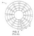
- FIG. 4is a top view of a conventional disk and illustrates tracks and sectors, with each of the sectors being divided into a servo sector and a data sector.
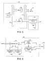
- FIG. 5is a block diagram of a host device that is connected to a disk drive, such as the disk drive shown in FIG. 1 , and that is configured in accordance with various embodiments of the present invention.
- FIG. 7is a block diagram that illustrates measured parameters that are embedded within data that is to be written to a disk, such as the disk of FIG. 4 , in accordance with some embodiments of the present invention.
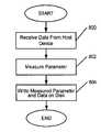
- FIG. 8illustrates a flowchart of operations for storing measured parameters with data on a disk in accordance with some embodiments of the present invention.
- the present inventionmay be embodied in hardware and/or in software (including firmware, resident software, micro-code, etc.). Consequently, as used herein, the term “signal” may take the form of a continuous waveform and/or discrete value(s), such as digital value(s) in a memory or register. Furthermore, the present invention may take the form of a computer program product on a computer-usable or computer-readable storage medium having computer-usable or computer-readable program code embodied in the medium for use by or in connection with an instruction execution system. In the context of this document, a computer-usable or computer-readable medium may be any medium that can contain, store, communicate, propagate, or transport the program for use by or in connection with the instruction execution system, apparatus, or device.
- FIG. 5is a block diagram of a host device 500 that is connected to a disk drive 502 , which may be configured as was described for the disk drive 10 of FIG. 1 .
- the disk drive 502is also configured to measure one or more parameters that are associated with the disk drive 502 , and to store the measured parameters with data from the host device 500 .
- the disk drive 502includes drive electronic circuits 520 , which may be included within the electronic circuits 30 of FIG. 1 , and a head disk assembly 522 (“HDA”) that can include the disk 34 , actuator assembly 18 and voice coil motor 28 of FIG. 1 .
- HDAhead disk assembly 522
- FIG. 6is a block diagram of at least a portion of the drive electronic circuits 520 of FIG. 5 and associated methods, in accordance with some embodiments of the present invention.
- the electronic circuits 520can include a data controller 600 , a read/write channel 602 , a servo controller 604 , a temperature sensor 606 , and an air pressure sensor 608 .
- the servo controller 604can communicate with the HDA 522 in a conventional manner to seek and follow selected tracks on the disk 34 .
- the read/write channel 602may operate in a conventional manner to convert data between the digital form used by the data controller 600 and the analog form used by the transducer 20 .
- the transducer 20generates a read signal based on the servo information (including preamble and servo burst patterns) and stored data on the disk 34 .
- the read/write channel 602provides the read signal to the data controller 600 and the servo controller 604 .
- the servo controller 604uses the servo information in the read signal to perform seek and track following operations of the transducer 20 relative to data tracks 40 .
- the data controller 600communicates with the read/write channel 602 to read data from the disk 34 , and provide the read data to the host device 500 , and to write data from the host device 500 to the disk 34 .
- the temperature sensor 606is configured to generate a temperature signal based on a sensed temperature of, for example, air in the disk drive 502 , one or more components of the drive electronics 520 , and/or the transducer 20 .
- the air pressure sensor 608is configured to generate a pressure signal based on a sensed air pressure in the disk drive 502 . Accordingly, the air pressure sensor 608 can provide an indication of altitude of the disk drive 502 .
- the data controller 600is configured to measure at least one parameter that is indicative of a time varying characteristic associated with the disk drive 502 , and to write the measured parameter on the disk 34 through the read/write channel 602 and the transducer 20 .
- the time varying characteristic that is measured by the data controller 600can include, but is not limited to, temperature, air pressure, flying height of the transducer 20 relative to the disk 34 , and/or a position error signal (PES) that is indicative of a radial location of the transducer 20 relative to a desired location along (e.g., a centerline of) a selected one of the tracks 40 ( FIG. 4 ).
- PESposition error signal
- the data controller 600may measure one or more of the parameters during at least a portion of time while data from the host device 500 ( FIG. 5 ) is written to the disk 34 .
- the parametersmay be measured while writing data on various of the data tracks 40 and data sectors 46 ( FIG. 4 ). Accordingly, the measured parameters can thereby indicate the conditions associated with various components in the disk drive 10 when the data was written on the disk 34 .
- the measured parameterscan be associated with particular portions of the written data, so that the conditions that were present when the associated data was written, can be later determined. The measured parameters may then be used to improve the accuracy with which data is read from the disk 34 , to assist with diagnosis of malfunction of the disk drive 10 , and/or to assist with remedying such malfunction.
- the measured flying height of the transducer 20 and the PESmay be used to improve read back of data, such as during error recovery when a threshold error rate is exceeded in read data. Because the flying height of the transducer 20 can affect the strength of the data component of the read signal, the data controller 600 may be configured to vary its bit detection algorithm/process for the read signal based on the measured flying height of the transducer 20 . Because the PES is indicative of a centerline along which the transducer 20 wrote the data on the disk 34 , the data controller 600 may radially offset the transducer 20 , via the servo controller 604 , based on the measured PES to improve alignment of the transducer 20 with the centerline of the written data when attempting to read the data. Thus, when a threshold error rate is exceed in read data, the data controller 600 may improve the accuracy with which it can read back the data using the measured flying height and/or the measured PES that is associated with the data.
- a gradual increase in PES over timemay indicate that sufficient dust/debris has accumulated-on (fouled) the transducer 20 so as to interfere with positioning of the transducer 20 .
- the data controller 600may respond to this PES indication by modifying how the servo controller 604 uses the PES to position the transducer 20 .
- the data controller 600may write the measured parameters onto the disk 34 in a manner that associates the measured parameters with particular portions of data that were written during, or proximate in time to, the measurement of the parameters.
- the measured parametersmay be written adjacent to the associated data on the disk 34 .
- the measured parametersmay be written in a same track and/or sector of a track on the disk 34 as at least a portion of the associated data. Additionally, or alternatively, the measured parameters may be embedded within the associated data.
- FIG. 7illustrates how measured parameters may be embedded within data that is to be written on the disk 34 , in accordance with some embodiments of the present invention.
- the data controller 600is configured to encode data 700 that is received from the host device 500 before it is written on the disk 34 .
- the data controller 600can encode portions (e.g., bytes) of the received data 700 as symbols 702 for writing on the disk 34 .
- Each of the symbolscan have a predetermined length (e.g., 10 bits).
- the last encoded symbol 708can have space, referred to as pad space 710 , that is not occupied by the coded data.
- the pad space 710is used to store at least a portion of the measured parameters 712 .
- the measured parameters 712may be embedded within a single pad space 710 of the symbol 708 , or they may be spread over a series of available pad spaces 710 of the sequential coded end symbols 708 .
- Cyclic redundancy check (CRC) bytesmay be combined with the received data 700 before it is encoded.
- Error correction code (ECC) bytes 714may be combined with the symbols 702 .
- the symbols and associated ECC bitsmay then written as-is, or may be further encoded and then written on the disk 34 .
- received datais divided into lengths of 512 bytes for coding.
- Two CRC bytesare added to the 512 byte data, resulting in 514 bytes, or 4112 bits (i.e., 514*8 bits/byte) for coding.
- the symbol lengthis 10 bits
- the coded data and CRC bytesare represented by 411.2 symbols. Accordingly, one of the symbols has a pad space of 8 bits (i.e., 10 bits/symbol*0.2 symbols). The 8 bit pad available for use in embedding at least a portion of the measured parameters.
- the data controller 600can separate the embedded measured parameters from the data during decoding of the data symbols that are read from the disk 34 .
- the data, without the measured parameters,may then be provided to the host device 500 , and the measured parameters may be used as explained herein.
- the measured parameterscan be read during the reading of the data from the disk 34 .
- the measured parametersmay then be timely used to modify the positioning of the transducer 20 and/or the detection of the data in the read signal as was explained above.
- the measured parametersmay be retrieved without interfering with the reading of the data (e.g., without causing seeking operations).
- the measured parametersWhen the measured parameters are embedded within pad spaces of symbols, they may be stored without loss of data storage capacity of the disk 34 .
- the data controller 600may embed a sequential number sequence with the data that is written on the disk 34 .
- the data controller 600may generate the sequential number sequence by counting sectors 42 around the disk 34 , so that each number in the sequence is indicative of a particular sector.
- the data controller 600may then select a number in the sequence that corresponds to a sector in which data is to be written, and may embed the selected number in the data and provide the combined data to the read/write channel 602 for writing in that sector on the disk 34 .
- the data on the disk 34can thereby include an indication of what sector it was intended to be written.
- the data controller 600may be configured to prevent access to the data, and/or to generate an indication to the host device 500 , when movement/copying of the data is identified.
- the data controller 600may additionally, or alternatively, write the measured parameters to a portion of the disk 34 that is reserved for storing parameters. For example, parameters that are measured during several different write operations can be stored in a portion of the disk 34 that is reserved for storing parameters and not data.
- the electronic circuits 520may be configured to allow a user to define which parameters are measured, when they are measured (such as during write operations, or at a specified time/day/date) and/or how often they are to be measured.
- the usermay also define whether the parameters are to be embedded in the data, or whether they are to be stored in a reserved portion of the disk 34 .
- the size of the reserved portion of the disk 34may also be defined by the user.
- FIG. 8illustrates a flowchart of operations for storing measured parameters with data on a disk in a disk drive. These operations can be suitable for use by the drive electronic circuits 520 shown in FIG. 5 , and the data controller 600 shown in FIG. 6 .
- datais received from a host device.
- at least one parameter that is indicative of a time varying characteristic associated with the disk driveis measured.
- the measured parameter and the dataare written on the disk through a transducer.
- the measured parametermay be combined with the data, such as by embedding the measured parameter with the data, when it is written on the disk, and/or the measured parameter may be written to a portion of the disk that is reserved for storing such parameters.
Landscapes
- Engineering & Computer Science (AREA)
- Signal Processing (AREA)
- Signal Processing For Digital Recording And Reproducing (AREA)
Abstract
Description
Claims (18)
Priority Applications (1)
| Application Number | Priority Date | Filing Date | Title |
|---|---|---|---|
| US11/042,931US7154700B1 (en) | 2004-07-31 | 2005-01-25 | Disk drive that stores time varying characteristics thereof with data from a host device and associated methods |
Applications Claiming Priority (2)
| Application Number | Priority Date | Filing Date | Title |
|---|---|---|---|
| US58740604P | 2004-07-31 | 2004-07-31 | |
| US11/042,931US7154700B1 (en) | 2004-07-31 | 2005-01-25 | Disk drive that stores time varying characteristics thereof with data from a host device and associated methods |
Publications (1)
| Publication Number | Publication Date |
|---|---|
| US7154700B1true US7154700B1 (en) | 2006-12-26 |
Family
ID=37569486
Family Applications (1)
| Application Number | Title | Priority Date | Filing Date |
|---|---|---|---|
| US11/042,931Expired - Fee RelatedUS7154700B1 (en) | 2004-07-31 | 2005-01-25 | Disk drive that stores time varying characteristics thereof with data from a host device and associated methods |
Country Status (1)
| Country | Link |
|---|---|
| US (1) | US7154700B1 (en) |
Cited By (4)
| Publication number | Priority date | Publication date | Assignee | Title |
|---|---|---|---|---|
| US7253984B1 (en)* | 2004-09-02 | 2007-08-07 | Maxtor Corporation | Disk drive that generates a position error signal and a fly height signal from a servo burst pattern |
| US20080273262A1 (en)* | 2007-01-05 | 2008-11-06 | Hitachi Global Storage Technologies Inc. Netherlands B.V. | Magnetic disk drive, preamplifier for magnetic disk drive, flexible printed cable assembly for magnetic disk drive |
| US20100238585A1 (en)* | 2009-03-17 | 2010-09-23 | Samsung Electronics Co., Ltd. | Method of controlling flying height of magnetic head of hard disk drive |
| US7933087B1 (en) | 2008-06-18 | 2011-04-26 | Western Digital Technologies, Inc. | Disk drive storing parameters of a write operation in a plurality of data sectors |
Citations (18)
| Publication number | Priority date | Publication date | Assignee | Title |
|---|---|---|---|---|
| US4167109A (en)* | 1978-06-22 | 1979-09-11 | Raymond Gold | Process for measuring temperature with solid state track recorders |
| US4691258A (en)* | 1984-03-30 | 1987-09-01 | International Business Machines Corporation | Temperature compensating mechanism for positioning of a magnetic head of a magnetic disk drive |
| US4979054A (en)* | 1988-02-25 | 1990-12-18 | Tandon Corporation | Disk drive for storing data in run length limited format and method of providing such format |
| US5377058A (en)* | 1992-12-31 | 1994-12-27 | International Business Machines Corporation | Fly height servo control of read/write head suspension |
| US5835299A (en)* | 1995-08-25 | 1998-11-10 | Samsung Electronics Co., Ltd. | Method for optimizing skew of hard disk drive |
| US6101053A (en)* | 1997-05-29 | 2000-08-08 | Fujitsu Limited | Write condition setting method and disk unit |
| US6359749B1 (en)* | 1999-10-15 | 2002-03-19 | International Business Machines Corporation | Dual element head with radial offset optimized for minimal write-to-read track error |
| US6671232B1 (en)* | 2001-07-25 | 2003-12-30 | Maxtor Corporation | Method and apparatus for measuring the surface temperature of a disk |
| US6781786B2 (en)* | 2002-02-21 | 2004-08-24 | Fujitsu Limited | Magnetic disk drive system |
| US20040174627A1 (en)* | 2002-12-13 | 2004-09-09 | Samsung Electronics Co., Ltd. | Methods of optimizing recording current and setting recording density of hard disk drive |
| US20050078393A1 (en)* | 2003-10-08 | 2005-04-14 | Samsung Electronics Co., Ltd. | Method for determining a type of head, and method for optimizing a write parameter using the head type determining method in a hard disc drive |
| US20050078404A1 (en)* | 2003-10-09 | 2005-04-14 | Hitachi Global Storage Technologies Netherlands, B.V. | Data storage device and actuator control method |
| US6914738B2 (en)* | 2002-05-31 | 2005-07-05 | Kabushiki Kaisha Toshiba | Apparatus and method for controlling write current supplied to head |
| US6972920B2 (en)* | 2002-09-19 | 2005-12-06 | Samsung Electronics Co., Ltd. | Method and apparatus for preventing adjacent track erase in HDD |
| US6987628B1 (en)* | 2000-07-13 | 2006-01-17 | Maxtor Corporation | Method and apparatus for high fly write detection using stored amplitude values |
| US7031091B2 (en)* | 2002-09-18 | 2006-04-18 | Hitachi, Ltd. | Magnetic recording apparatus and method of writing data at low temperature |
| US7036066B2 (en)* | 2002-05-24 | 2006-04-25 | Sun Microsystems, Inc. | Error detection using data block mapping |
| US7046463B2 (en)* | 2002-03-28 | 2006-05-16 | Seagate Technology Llc | Low flying head detection using readback signal amplitude modulation |
- 2005
- 2005-01-25USUS11/042,931patent/US7154700B1/ennot_activeExpired - Fee Related
Patent Citations (18)
| Publication number | Priority date | Publication date | Assignee | Title |
|---|---|---|---|---|
| US4167109A (en)* | 1978-06-22 | 1979-09-11 | Raymond Gold | Process for measuring temperature with solid state track recorders |
| US4691258A (en)* | 1984-03-30 | 1987-09-01 | International Business Machines Corporation | Temperature compensating mechanism for positioning of a magnetic head of a magnetic disk drive |
| US4979054A (en)* | 1988-02-25 | 1990-12-18 | Tandon Corporation | Disk drive for storing data in run length limited format and method of providing such format |
| US5377058A (en)* | 1992-12-31 | 1994-12-27 | International Business Machines Corporation | Fly height servo control of read/write head suspension |
| US5835299A (en)* | 1995-08-25 | 1998-11-10 | Samsung Electronics Co., Ltd. | Method for optimizing skew of hard disk drive |
| US6101053A (en)* | 1997-05-29 | 2000-08-08 | Fujitsu Limited | Write condition setting method and disk unit |
| US6359749B1 (en)* | 1999-10-15 | 2002-03-19 | International Business Machines Corporation | Dual element head with radial offset optimized for minimal write-to-read track error |
| US6987628B1 (en)* | 2000-07-13 | 2006-01-17 | Maxtor Corporation | Method and apparatus for high fly write detection using stored amplitude values |
| US6671232B1 (en)* | 2001-07-25 | 2003-12-30 | Maxtor Corporation | Method and apparatus for measuring the surface temperature of a disk |
| US6781786B2 (en)* | 2002-02-21 | 2004-08-24 | Fujitsu Limited | Magnetic disk drive system |
| US7046463B2 (en)* | 2002-03-28 | 2006-05-16 | Seagate Technology Llc | Low flying head detection using readback signal amplitude modulation |
| US7036066B2 (en)* | 2002-05-24 | 2006-04-25 | Sun Microsystems, Inc. | Error detection using data block mapping |
| US6914738B2 (en)* | 2002-05-31 | 2005-07-05 | Kabushiki Kaisha Toshiba | Apparatus and method for controlling write current supplied to head |
| US7031091B2 (en)* | 2002-09-18 | 2006-04-18 | Hitachi, Ltd. | Magnetic recording apparatus and method of writing data at low temperature |
| US6972920B2 (en)* | 2002-09-19 | 2005-12-06 | Samsung Electronics Co., Ltd. | Method and apparatus for preventing adjacent track erase in HDD |
| US20040174627A1 (en)* | 2002-12-13 | 2004-09-09 | Samsung Electronics Co., Ltd. | Methods of optimizing recording current and setting recording density of hard disk drive |
| US20050078393A1 (en)* | 2003-10-08 | 2005-04-14 | Samsung Electronics Co., Ltd. | Method for determining a type of head, and method for optimizing a write parameter using the head type determining method in a hard disc drive |
| US20050078404A1 (en)* | 2003-10-09 | 2005-04-14 | Hitachi Global Storage Technologies Netherlands, B.V. | Data storage device and actuator control method |
Cited By (5)
| Publication number | Priority date | Publication date | Assignee | Title |
|---|---|---|---|---|
| US7253984B1 (en)* | 2004-09-02 | 2007-08-07 | Maxtor Corporation | Disk drive that generates a position error signal and a fly height signal from a servo burst pattern |
| US20080273262A1 (en)* | 2007-01-05 | 2008-11-06 | Hitachi Global Storage Technologies Inc. Netherlands B.V. | Magnetic disk drive, preamplifier for magnetic disk drive, flexible printed cable assembly for magnetic disk drive |
| US7630160B2 (en)* | 2007-01-05 | 2009-12-08 | Hitachi Global Storage Technologies Netherlands B.V. | Magnetic disk drive, preamplifier for magnetic disk drive, flexible printed cable assembly for magnetic disk drive |
| US7933087B1 (en) | 2008-06-18 | 2011-04-26 | Western Digital Technologies, Inc. | Disk drive storing parameters of a write operation in a plurality of data sectors |
| US20100238585A1 (en)* | 2009-03-17 | 2010-09-23 | Samsung Electronics Co., Ltd. | Method of controlling flying height of magnetic head of hard disk drive |
Similar Documents
| Publication | Publication Date | Title |
|---|---|---|
| US6754030B2 (en) | Optimal reader-to-writer offset measurement of a head in a disc drive for reduced track misregistration | |
| US7423828B2 (en) | Off-track write error recovery | |
| US6219814B1 (en) | Method and apparatus for selectively varying error correcting code (ECC) power in a direct access storage device (DASD) | |
| US6490691B1 (en) | Error recovery in a disk drive | |
| US6873488B2 (en) | Enhanced MR offset with dynamic tuning range | |
| US7345837B1 (en) | Disk drive that refreshes data on portions of a disk based on a number of write operations thereto | |
| US7984359B2 (en) | Correction of data errors in a memory buffer | |
| JP4564692B2 (en) | Hard disk drive, defect type detection method on disk, and defect detection method | |
| JP2003022623A (en) | Method for deciding position of conversion head on disk surface, and disk drive | |
| JPH11507462A (en) | Adaptive control of write inhibit signal in disk drive | |
| CN101930777A (en) | Disk drives and data rewriting methods | |
| US20090150637A1 (en) | Method and system for dynamically allocating read and write sequence randomizer | |
| US7206990B2 (en) | Data sector error handling mechanism | |
| US6798594B2 (en) | Position sensing system for a disc drive using micro-servo sectors and side-by-side R/W recording elements | |
| JP3865723B2 (en) | Method for recording data in hard disk drive and control device therefor | |
| KR100262430B1 (en) | Servo positioning system, user data recording apparatus and direct access storage apparatus | |
| US7154700B1 (en) | Disk drive that stores time varying characteristics thereof with data from a host device and associated methods | |
| KR100268096B1 (en) | Method and error correcting code apparatus for storing predefined information with ecc in a direct access storage device | |
| US8817412B1 (en) | Magnetic disk device and writing method of a magnetic disk | |
| US7898757B2 (en) | Hard disk drive with divided data sectors and hard disk drive controller for controlling the same | |
| US20040264021A1 (en) | Multi-tracks mr offset tuning based on error count in certification process | |
| US6788489B1 (en) | Employing off-track capability in data access operations in a direct access storage device | |
| JP4327824B2 (en) | Magnetic disk device, servo writing method and inspection method | |
| US7184241B1 (en) | Disk drive that performs cold writes to erased buffer | |
| US6009537A (en) | Disk wear prevention by relocating data in response to a head slide count |
Legal Events
| Date | Code | Title | Description |
|---|---|---|---|
| AS | Assignment | Owner name:MAXTOR CORPORATION, COLORADO Free format text:ASSIGNMENT OF ASSIGNORS INTEREST;ASSIGNORS:SCHRECK, ERHARD;BRUNNETT, DONALD;WARNER, NICK;AND OTHERS;REEL/FRAME:016203/0622 Effective date:20050107 | |
| AS | Assignment | Owner name:WELLS FARGO BANK, NATIONAL ASSOCIATION, AS COLLATERAL AGENT AND SECOND PRIORITY REPRESENTATIVE, CALIFORNIA Free format text:SECURITY AGREEMENT;ASSIGNORS:MAXTOR CORPORATION;SEAGATE TECHNOLOGY LLC;SEAGATE TECHNOLOGY INTERNATIONAL;REEL/FRAME:022757/0017 Effective date:20090507 Owner name:JPMORGAN CHASE BANK, N.A., AS ADMINISTRATIVE AGENT AND FIRST PRIORITY REPRESENTATIVE, NEW YORK Free format text:SECURITY AGREEMENT;ASSIGNORS:MAXTOR CORPORATION;SEAGATE TECHNOLOGY LLC;SEAGATE TECHNOLOGY INTERNATIONAL;REEL/FRAME:022757/0017 Effective date:20090507 Owner name:JPMORGAN CHASE BANK, N.A., AS ADMINISTRATIVE AGENT Free format text:SECURITY AGREEMENT;ASSIGNORS:MAXTOR CORPORATION;SEAGATE TECHNOLOGY LLC;SEAGATE TECHNOLOGY INTERNATIONAL;REEL/FRAME:022757/0017 Effective date:20090507 Owner name:WELLS FARGO BANK, NATIONAL ASSOCIATION, AS COLLATE Free format text:SECURITY AGREEMENT;ASSIGNORS:MAXTOR CORPORATION;SEAGATE TECHNOLOGY LLC;SEAGATE TECHNOLOGY INTERNATIONAL;REEL/FRAME:022757/0017 Effective date:20090507 | |
| FPAY | Fee payment | Year of fee payment:4 | |
| AS | Assignment | Owner name:MAXTOR CORPORATION, CALIFORNIA Free format text:RELEASE;ASSIGNOR:JPMORGAN CHASE BANK, N.A., AS ADMINISTRATIVE AGENT;REEL/FRAME:025662/0001 Effective date:20110114 Owner name:SEAGATE TECHNOLOGY HDD HOLDINGS, CALIFORNIA Free format text:RELEASE;ASSIGNOR:JPMORGAN CHASE BANK, N.A., AS ADMINISTRATIVE AGENT;REEL/FRAME:025662/0001 Effective date:20110114 Owner name:SEAGATE TECHNOLOGY LLC, CALIFORNIA Free format text:RELEASE;ASSIGNOR:JPMORGAN CHASE BANK, N.A., AS ADMINISTRATIVE AGENT;REEL/FRAME:025662/0001 Effective date:20110114 Owner name:SEAGATE TECHNOLOGY INTERNATIONAL, CALIFORNIA Free format text:RELEASE;ASSIGNOR:JPMORGAN CHASE BANK, N.A., AS ADMINISTRATIVE AGENT;REEL/FRAME:025662/0001 Effective date:20110114 | |
| AS | Assignment | Owner name:THE BANK OF NOVA SCOTIA, AS ADMINISTRATIVE AGENT, CANADA Free format text:SECURITY AGREEMENT;ASSIGNOR:SEAGATE TECHNOLOGY LLC;REEL/FRAME:026010/0350 Effective date:20110118 Owner name:THE BANK OF NOVA SCOTIA, AS ADMINISTRATIVE AGENT, Free format text:SECURITY AGREEMENT;ASSIGNOR:SEAGATE TECHNOLOGY LLC;REEL/FRAME:026010/0350 Effective date:20110118 | |
| AS | Assignment | Owner name:SEAGATE TECHNOLOGY INTERNATIONAL, CAYMAN ISLANDS Free format text:TERMINATION AND RELEASE OF SECURITY INTEREST IN PATENT RIGHTS;ASSIGNOR:WELLS FARGO BANK, NATIONAL ASSOCIATION, AS COLLATERAL AGENT AND SECOND PRIORITY REPRESENTATIVE;REEL/FRAME:030833/0001 Effective date:20130312 Owner name:SEAGATE TECHNOLOGY US HOLDINGS, INC., CALIFORNIA Free format text:TERMINATION AND RELEASE OF SECURITY INTEREST IN PATENT RIGHTS;ASSIGNOR:WELLS FARGO BANK, NATIONAL ASSOCIATION, AS COLLATERAL AGENT AND SECOND PRIORITY REPRESENTATIVE;REEL/FRAME:030833/0001 Effective date:20130312 Owner name:SEAGATE TECHNOLOGY LLC, CALIFORNIA Free format text:TERMINATION AND RELEASE OF SECURITY INTEREST IN PATENT RIGHTS;ASSIGNOR:WELLS FARGO BANK, NATIONAL ASSOCIATION, AS COLLATERAL AGENT AND SECOND PRIORITY REPRESENTATIVE;REEL/FRAME:030833/0001 Effective date:20130312 Owner name:EVAULT INC. (F/K/A I365 INC.), CALIFORNIA Free format text:TERMINATION AND RELEASE OF SECURITY INTEREST IN PATENT RIGHTS;ASSIGNOR:WELLS FARGO BANK, NATIONAL ASSOCIATION, AS COLLATERAL AGENT AND SECOND PRIORITY REPRESENTATIVE;REEL/FRAME:030833/0001 Effective date:20130312 | |
| FPAY | Fee payment | Year of fee payment:8 | |
| FEPP | Fee payment procedure | Free format text:MAINTENANCE FEE REMINDER MAILED (ORIGINAL EVENT CODE: REM.) | |
| LAPS | Lapse for failure to pay maintenance fees | Free format text:PATENT EXPIRED FOR FAILURE TO PAY MAINTENANCE FEES (ORIGINAL EVENT CODE: EXP.); ENTITY STATUS OF PATENT OWNER: LARGE ENTITY | |
| STCH | Information on status: patent discontinuation | Free format text:PATENT EXPIRED DUE TO NONPAYMENT OF MAINTENANCE FEES UNDER 37 CFR 1.362 | |
| FP | Lapsed due to failure to pay maintenance fee | Effective date:20181226 | |
| AS | Assignment | Owner name:SEAGATE TECHNOLOGY PUBLIC LIMITED COMPANY, CALIFORNIA Free format text:RELEASE BY SECURED PARTY;ASSIGNOR:THE BANK OF NOVA SCOTIA;REEL/FRAME:072193/0001 Effective date:20250303 Owner name:SEAGATE TECHNOLOGY, CALIFORNIA Free format text:RELEASE BY SECURED PARTY;ASSIGNOR:THE BANK OF NOVA SCOTIA;REEL/FRAME:072193/0001 Effective date:20250303 Owner name:SEAGATE TECHNOLOGY HDD HOLDINGS, CALIFORNIA Free format text:RELEASE BY SECURED PARTY;ASSIGNOR:THE BANK OF NOVA SCOTIA;REEL/FRAME:072193/0001 Effective date:20250303 Owner name:I365 INC., CALIFORNIA Free format text:RELEASE BY SECURED PARTY;ASSIGNOR:THE BANK OF NOVA SCOTIA;REEL/FRAME:072193/0001 Effective date:20250303 Owner name:SEAGATE TECHNOLOGY LLC, CALIFORNIA Free format text:RELEASE BY SECURED PARTY;ASSIGNOR:THE BANK OF NOVA SCOTIA;REEL/FRAME:072193/0001 Effective date:20250303 Owner name:SEAGATE TECHNOLOGY INTERNATIONAL, CAYMAN ISLANDS Free format text:RELEASE BY SECURED PARTY;ASSIGNOR:THE BANK OF NOVA SCOTIA;REEL/FRAME:072193/0001 Effective date:20250303 Owner name:SEAGATE HDD CAYMAN, CAYMAN ISLANDS Free format text:RELEASE BY SECURED PARTY;ASSIGNOR:THE BANK OF NOVA SCOTIA;REEL/FRAME:072193/0001 Effective date:20250303 Owner name:SEAGATE TECHNOLOGY (US) HOLDINGS, INC., CALIFORNIA Free format text:RELEASE BY SECURED PARTY;ASSIGNOR:THE BANK OF NOVA SCOTIA;REEL/FRAME:072193/0001 Effective date:20250303 |