US7154191B2 - Electrical machine with double-sided rotor - Google Patents
Electrical machine with double-sided rotorDownload PDFInfo
- Publication number
- US7154191B2 US7154191B2US10/882,911US88291104AUS7154191B2US 7154191 B2US7154191 B2US 7154191B2US 88291104 AUS88291104 AUS 88291104AUS 7154191 B2US7154191 B2US 7154191B2
- Authority
- US
- United States
- Prior art keywords
- stator core
- wind turbine
- generator
- turbine generator
- permanent magnet
- Prior art date
- Legal status (The legal status is an assumption and is not a legal conclusion. Google has not performed a legal analysis and makes no representation as to the accuracy of the status listed.)
- Expired - Fee Related, expires
Links
- 238000001816coolingMethods0.000claimsdescription51
- 238000004804windingMethods0.000claimsdescription10
- 239000007788liquidSubstances0.000claimsdescription8
- 239000007769metal materialSubstances0.000claimsdescription6
- 238000012546transferMethods0.000claimsdescription6
- 230000004907fluxEffects0.000claimsdescription5
- 230000010349pulsationEffects0.000claimsdescription3
- 239000003570airSubstances0.000description16
- 230000008901benefitEffects0.000description6
- 239000000463materialSubstances0.000description6
- 230000004323axial lengthEffects0.000description5
- 230000005611electricityEffects0.000description3
- 239000012080ambient airSubstances0.000description2
- 238000010276constructionMethods0.000description2
- 238000013461designMethods0.000description2
- 238000009434installationMethods0.000description2
- 238000000034methodMethods0.000description2
- 238000012986modificationMethods0.000description2
- 230000004048modificationEffects0.000description2
- 230000009467reductionEffects0.000description2
- 239000010959steelSubstances0.000description2
- XLYOFNOQVPJJNP-UHFFFAOYSA-NwaterSubstancesOXLYOFNOQVPJJNP-UHFFFAOYSA-N0.000description2
- 229910000838Al alloyInorganic materials0.000description1
- 229910000851Alloy steelInorganic materials0.000description1
- 229920000049Carbon (fiber)Polymers0.000description1
- RYGMFSIKBFXOCR-UHFFFAOYSA-NCopperChemical compound[Cu]RYGMFSIKBFXOCR-UHFFFAOYSA-N0.000description1
- 229910001141Ductile ironInorganic materials0.000description1
- 229910001060Gray ironInorganic materials0.000description1
- FYYHWMGAXLPEAU-UHFFFAOYSA-NMagnesiumChemical compound[Mg]FYYHWMGAXLPEAU-UHFFFAOYSA-N0.000description1
- 229910000831SteelInorganic materials0.000description1
- RTAQQCXQSZGOHL-UHFFFAOYSA-NTitaniumChemical compound[Ti]RTAQQCXQSZGOHL-UHFFFAOYSA-N0.000description1
- 229910001037White ironInorganic materials0.000description1
- 239000011149active materialSubstances0.000description1
- XAGFODPZIPBFFR-UHFFFAOYSA-NaluminiumChemical compound[Al]XAGFODPZIPBFFR-UHFFFAOYSA-N0.000description1
- 229910052782aluminiumInorganic materials0.000description1
- 238000013459approachMethods0.000description1
- 230000009286beneficial effectEffects0.000description1
- 239000004917carbon fiberSubstances0.000description1
- 238000005266castingMethods0.000description1
- 238000006243chemical reactionMethods0.000description1
- 239000000110cooling liquidSubstances0.000description1
- 239000010949copperSubstances0.000description1
- 229910052802copperInorganic materials0.000description1
- 239000008367deionised waterSubstances0.000description1
- 238000005516engineering processMethods0.000description1
- 238000010438heat treatmentMethods0.000description1
- 238000003475laminationMethods0.000description1
- 229910052749magnesiumInorganic materials0.000description1
- 239000011777magnesiumSubstances0.000description1
- 230000005415magnetizationEffects0.000description1
- 230000007246mechanismEffects0.000description1
- VNWKTOKETHGBQD-UHFFFAOYSA-NmethaneChemical compoundCVNWKTOKETHGBQD-UHFFFAOYSA-N0.000description1
- 238000009428plumbingMethods0.000description1
- 230000008569processEffects0.000description1
- 238000005086pumpingMethods0.000description1
- 238000007789sealingMethods0.000description1
- 239000010935stainless steelSubstances0.000description1
- 229910001220stainless steelInorganic materials0.000description1
- 230000001360synchronised effectEffects0.000description1
- 239000010936titaniumSubstances0.000description1
- 229910052719titaniumInorganic materials0.000description1
Images


Classifications
- F—MECHANICAL ENGINEERING; LIGHTING; HEATING; WEAPONS; BLASTING
- F03—MACHINES OR ENGINES FOR LIQUIDS; WIND, SPRING, OR WEIGHT MOTORS; PRODUCING MECHANICAL POWER OR A REACTIVE PROPULSIVE THRUST, NOT OTHERWISE PROVIDED FOR
- F03D—WIND MOTORS
- F03D9/00—Adaptations of wind motors for special use; Combinations of wind motors with apparatus driven thereby; Wind motors specially adapted for installation in particular locations
- F03D9/20—Wind motors characterised by the driven apparatus
- F03D9/25—Wind motors characterised by the driven apparatus the apparatus being an electrical generator
- F—MECHANICAL ENGINEERING; LIGHTING; HEATING; WEAPONS; BLASTING
- F03—MACHINES OR ENGINES FOR LIQUIDS; WIND, SPRING, OR WEIGHT MOTORS; PRODUCING MECHANICAL POWER OR A REACTIVE PROPULSIVE THRUST, NOT OTHERWISE PROVIDED FOR
- F03D—WIND MOTORS
- F03D13/00—Assembly, mounting or commissioning of wind motors; Arrangements specially adapted for transporting wind motor components
- F03D13/20—Arrangements for mounting or supporting wind motors; Masts or towers for wind motors
- F—MECHANICAL ENGINEERING; LIGHTING; HEATING; WEAPONS; BLASTING
- F03—MACHINES OR ENGINES FOR LIQUIDS; WIND, SPRING, OR WEIGHT MOTORS; PRODUCING MECHANICAL POWER OR A REACTIVE PROPULSIVE THRUST, NOT OTHERWISE PROVIDED FOR
- F03D—WIND MOTORS
- F03D80/00—Details, components or accessories not provided for in groups F03D1/00 - F03D17/00
- F03D80/60—Cooling or heating of wind motors
- H—ELECTRICITY
- H02—GENERATION; CONVERSION OR DISTRIBUTION OF ELECTRIC POWER
- H02K—DYNAMO-ELECTRIC MACHINES
- H02K21/00—Synchronous motors having permanent magnets; Synchronous generators having permanent magnets
- H02K21/12—Synchronous motors having permanent magnets; Synchronous generators having permanent magnets with stationary armatures and rotating magnets
- H02K21/14—Synchronous motors having permanent magnets; Synchronous generators having permanent magnets with stationary armatures and rotating magnets with magnets rotating within the armatures
- H—ELECTRICITY
- H02—GENERATION; CONVERSION OR DISTRIBUTION OF ELECTRIC POWER
- H02K—DYNAMO-ELECTRIC MACHINES
- H02K21/00—Synchronous motors having permanent magnets; Synchronous generators having permanent magnets
- H02K21/12—Synchronous motors having permanent magnets; Synchronous generators having permanent magnets with stationary armatures and rotating magnets
- H02K21/22—Synchronous motors having permanent magnets; Synchronous generators having permanent magnets with stationary armatures and rotating magnets with magnets rotating around the armatures, e.g. flywheel magnetos
- H—ELECTRICITY
- H02—GENERATION; CONVERSION OR DISTRIBUTION OF ELECTRIC POWER
- H02K—DYNAMO-ELECTRIC MACHINES
- H02K5/00—Casings; Enclosures; Supports
- H02K5/04—Casings or enclosures characterised by the shape, form or construction thereof
- H02K5/20—Casings or enclosures characterised by the shape, form or construction thereof with channels or ducts for flow of cooling medium
- H02K5/207—Casings or enclosures characterised by the shape, form or construction thereof with channels or ducts for flow of cooling medium with openings in the casing specially adapted for ambient air
- H—ELECTRICITY
- H02—GENERATION; CONVERSION OR DISTRIBUTION OF ELECTRIC POWER
- H02K—DYNAMO-ELECTRIC MACHINES
- H02K7/00—Arrangements for handling mechanical energy structurally associated with dynamo-electric machines, e.g. structural association with mechanical driving motors or auxiliary dynamo-electric machines
- H02K7/18—Structural association of electric generators with mechanical driving motors, e.g. with turbines
- H02K7/1807—Rotary generators
- H02K7/1823—Rotary generators structurally associated with turbines or similar engines
- H02K7/183—Rotary generators structurally associated with turbines or similar engines wherein the turbine is a wind turbine
- H02K7/1838—Generators mounted in a nacelle or similar structure of a horizontal axis wind turbine
- H—ELECTRICITY
- H02—GENERATION; CONVERSION OR DISTRIBUTION OF ELECTRIC POWER
- H02K—DYNAMO-ELECTRIC MACHINES
- H02K9/00—Arrangements for cooling or ventilating
- H02K9/22—Arrangements for cooling or ventilating by solid heat conducting material embedded in, or arranged in contact with, the stator or rotor, e.g. heat bridges
- H02K9/225—Heat pipes
- F—MECHANICAL ENGINEERING; LIGHTING; HEATING; WEAPONS; BLASTING
- F05—INDEXING SCHEMES RELATING TO ENGINES OR PUMPS IN VARIOUS SUBCLASSES OF CLASSES F01-F04
- F05B—INDEXING SCHEME RELATING TO WIND, SPRING, WEIGHT, INERTIA OR LIKE MOTORS, TO MACHINES OR ENGINES FOR LIQUIDS COVERED BY SUBCLASSES F03B, F03D AND F03G
- F05B2220/00—Application
- F05B2220/70—Application in combination with
- F05B2220/706—Application in combination with an electrical generator
- F05B2220/7064—Application in combination with an electrical generator of the alternating current (A.C.) type
- F05B2220/70642—Application in combination with an electrical generator of the alternating current (A.C.) type of the synchronous type
- F—MECHANICAL ENGINEERING; LIGHTING; HEATING; WEAPONS; BLASTING
- F05—INDEXING SCHEMES RELATING TO ENGINES OR PUMPS IN VARIOUS SUBCLASSES OF CLASSES F01-F04
- F05B—INDEXING SCHEME RELATING TO WIND, SPRING, WEIGHT, INERTIA OR LIKE MOTORS, TO MACHINES OR ENGINES FOR LIQUIDS COVERED BY SUBCLASSES F03B, F03D AND F03G
- F05B2220/00—Application
- F05B2220/70—Application in combination with
- F05B2220/706—Application in combination with an electrical generator
- F05B2220/7066—Application in combination with an electrical generator via a direct connection, i.e. a gearless transmission
- F—MECHANICAL ENGINEERING; LIGHTING; HEATING; WEAPONS; BLASTING
- F05—INDEXING SCHEMES RELATING TO ENGINES OR PUMPS IN VARIOUS SUBCLASSES OF CLASSES F01-F04
- F05B—INDEXING SCHEME RELATING TO WIND, SPRING, WEIGHT, INERTIA OR LIKE MOTORS, TO MACHINES OR ENGINES FOR LIQUIDS COVERED BY SUBCLASSES F03B, F03D AND F03G
- F05B2220/00—Application
- F05B2220/70—Application in combination with
- F05B2220/706—Application in combination with an electrical generator
- F05B2220/7068—Application in combination with an electrical generator equipped with permanent magnets
- H—ELECTRICITY
- H02—GENERATION; CONVERSION OR DISTRIBUTION OF ELECTRIC POWER
- H02K—DYNAMO-ELECTRIC MACHINES
- H02K16/00—Machines with more than one rotor or stator
- H02K16/04—Machines with one rotor and two stators
- H—ELECTRICITY
- H02—GENERATION; CONVERSION OR DISTRIBUTION OF ELECTRIC POWER
- H02K—DYNAMO-ELECTRIC MACHINES
- H02K5/00—Casings; Enclosures; Supports
- H02K5/04—Casings or enclosures characterised by the shape, form or construction thereof
- H02K5/20—Casings or enclosures characterised by the shape, form or construction thereof with channels or ducts for flow of cooling medium
- H02K5/203—Casings or enclosures characterised by the shape, form or construction thereof with channels or ducts for flow of cooling medium specially adapted for liquids, e.g. cooling jackets
- Y—GENERAL TAGGING OF NEW TECHNOLOGICAL DEVELOPMENTS; GENERAL TAGGING OF CROSS-SECTIONAL TECHNOLOGIES SPANNING OVER SEVERAL SECTIONS OF THE IPC; TECHNICAL SUBJECTS COVERED BY FORMER USPC CROSS-REFERENCE ART COLLECTIONS [XRACs] AND DIGESTS
- Y02—TECHNOLOGIES OR APPLICATIONS FOR MITIGATION OR ADAPTATION AGAINST CLIMATE CHANGE
- Y02E—REDUCTION OF GREENHOUSE GAS [GHG] EMISSIONS, RELATED TO ENERGY GENERATION, TRANSMISSION OR DISTRIBUTION
- Y02E10/00—Energy generation through renewable energy sources
- Y02E10/70—Wind energy
- Y02E10/72—Wind turbines with rotation axis in wind direction
- Y—GENERAL TAGGING OF NEW TECHNOLOGICAL DEVELOPMENTS; GENERAL TAGGING OF CROSS-SECTIONAL TECHNOLOGIES SPANNING OVER SEVERAL SECTIONS OF THE IPC; TECHNICAL SUBJECTS COVERED BY FORMER USPC CROSS-REFERENCE ART COLLECTIONS [XRACs] AND DIGESTS
- Y02—TECHNOLOGIES OR APPLICATIONS FOR MITIGATION OR ADAPTATION AGAINST CLIMATE CHANGE
- Y02E—REDUCTION OF GREENHOUSE GAS [GHG] EMISSIONS, RELATED TO ENERGY GENERATION, TRANSMISSION OR DISTRIBUTION
- Y02E10/00—Energy generation through renewable energy sources
- Y02E10/70—Wind energy
- Y02E10/728—Onshore wind turbines
Definitions
- the present inventionrelates generally to electrical machines and more specifically to wind turbine generators and ship propulsion motors.
- Windis usually considered to be a form of solar energy. Wind is caused by the uneven heating of the atmosphere by the sun, the irregularities of the earth's surface, and rotation of the earth, and wind flow patterns are modified by the earth's terrain, bodies of water, and vegetation.
- the terms wind energy or wind powerdescribe the process by which the wind is used to generate mechanical power or electricity.
- wind turbinesare used to convert the kinetic energy in the wind into mechanical power.
- This mechanical powermay be used for specific tasks (such as grinding grain or pumping water) or a generator may convert this mechanical power into electricity.
- a wind turbineusually includes an aerodynamic mechanism for converting the movement of air into a mechanical motion which is then converted with a generator into electrical power. Power output from the generator is approximately proportional to the cube of the wind speed. As wind speed doubles, the capacity of wind generators increases almost eightfold.
- the majority of commercially available wind turbinesutilize geared drive trains to connect the turbine blades to the wind generators.
- the windturns the turbine blades, which spin a shaft, which feeds into a gear-box and then connects to a wind generator and makes electricity.
- the geared driveaims to increase the velocity of the mechanical motion.
- the drawback of a geared driveis that it reduces the reliability of the wind turbine and increases the noise and cost of the wind turbine.
- a wind turbineis provided.
- the generator of the wind turbineincludes at least two concentric air gaps.
- the generatorcomprises at least one double-sided rotor with an inner rotor side and an outer rotor side, and at least one stator with an inner stator core and an outer stator core.
- the at least one double-sided rotoris concentrically disposed between the inner stator core and the outer stator core.
- a wind turbine generatorin accordance with another embodiment of the present invention, includes at least two concentric air gaps.
- the generatorcomprises at least one double-sided rotor with an inner rotor side and an outer rotor side, and at least one stator with an inner stator core and an outer stator core.
- the at least one double-sided rotoris concentrically disposed between the inner stator core and the outer stator core.
- a ship propulsion motorin accordance with another embodiment of the present invention, includes at least two concentric air gaps.
- the motorcomprises at least one double-sided rotor with an inner rotor side and an outer rotor side, and at least one stator with an inner stator core and an outer stator core.
- the at least one double-sided rotoris concentrically disposed between the inner stator core and the outer stator core.
- FIG. 1illustrates a sectional view of a wind turbine comprising an exemplary double-sided generator
- FIG. 2illustrates a sectional view of the exemplary generator of FIG. 1 with a double-sided rotor and a stator;
- FIG. 3illustrates a three-dimensional view of the double-sided rotor and stator of FIG. 2 .
- FIG. 4illustrates an exemplary embodiment with a heat pipe and an outer cooling channel in the arrangement of FIG. 2 ;
- FIG. 5illustrates a sectional view of a portion of a ship comprising an exemplary double-sided ship propulsion motor
- FIG. 6illustrates a section view of the exemplary motor of FIG. 5 ;
- FIG. 7illustrates an exemplary embodiment with the gear box used with the double-sided generator of FIG. 2 .
- the present inventionincludes different embodiments for double-sided generators and motors that are particularly useful for direct-drive wind turbines and ship propulsion units. Additionally these embodiments may be beneficial for some geared electrical machines.
- the different configurations described herein beloware based upon a double-sided, radial-flux, synchronous electrical machines. Although permanent magnet (PM) machines are described and shown for purposes of illustration, other electrical machines such as wound field machines can alternatively be used. These configurations contribute towards achieving cost-effective wind turbines of increased power ratings (>2.0 MW) and are especially advantageous for land-based applications where the outside diameter may be constrained by transportation limitations.
- PMpermanent magnet
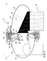
- FIG. 1is a diagrammatic representation of a sectional view of a wind turbine 10 with an exemplary embodiment of a direct-drive double-sided PM generator 12 .
- the PM generator 12 of the wind turbine 10includes at least two concentric air gaps (not shown in FIG. 1 and discussed later in reference to FIG. 2 ), thereby effectively converting the PM generator 12 into two concentric generators.
- the PM generator 12can produce considerably more power output than a single-sided generator.
- a 2 MW single-sided generatormight be replaced by a double-sided generator capable of producing 3–3.6 MW for the same total diameter and axial length.
- a 3 MW single-sided PM generator having a diameter of 6 metersmight be replaced with a double-sided generator of the same axial length with only a 4.3 meters diameter, thereby enabling land-transportation of the entire generator as one unit.
- FIG. 1One exemplary embodiment of the wind turbine 10 , as shown in FIG. 1 includes a double-sided rotor 86 and a stator 88 in the PM generator 12 .
- Stator 88includes an inner stator core 90 and the outer stator core 92 and these contribute to the at least two concentric air gaps (shown in subsequent figures).
- Stator 88is concentrically mounted within the stationary frame 34 .
- the PM generator 12further includes, in one example, a cooling channel 100 for cooling the inner stator core 90 and the outer stator core 92 .
- the power output of the stator 88is fed and controlled by a power converter unit (not shown) capable of full power conversion.
- the stator 88is connected to a stationary frame 34 , which is further mounted to a main frame 36 .
- the main frameis further mounted to a tower 38 through a conventional yaw bearing and gear drive system (not shown).
- cooling channels 100use wind for cooling the inner stator core 90 and the outer stator core 92 .
- the wind turbine 10 as shown in FIG. 1also includes rotor blades 42 connected to a rotor blade hub 44 which has a rotor hub cover 49 .
- the rotor blade hub 44connects to the double-sided rotor 86 (which comprises a generator rotor) through a rotor shaft 46 .
- Double-sided rotor 86is connected to a rotating frame 52 .
- Double-sided rotor 86also attaches to a stationary hub 56 .
- a nacelle cover 50typically protects the components inside the nacelle.
- Rotor blade hub 44is further mounted to a flange 54 on the main rotating shaft 46 (rotor shaft) of a main stationary hub and bearing assembly 56 .
- This assembly 56connects the rotor blade hub 44 to the main frame 36 .
- two main bearings, front main bearing 58 and rear main bearing 60are illustrated, alternative bearings configurations, including a single main bearing, are possible.
- Access to the rotor blade hub 44is obtained through either access ports in the rotating and stationary frames (i.e., between the PM generator 12 and the main bearing assembly 56 ), or optionally through the main shaft and bearing assembly 56 .
- the main bearing and shaft diametersmay be sized accordingly with the means for hub access; e.g., larger-diameter main bearings (about 1.5 meters or more outside diameter, for example) would facilitate hub access.
- Assembly of the wind turbine 10 at the installation siteis typically done by first lifting the main frame 36 , followed by the PM generator 12 (including the main shaft and bearing assembly 56 ), followed by the turbine rotor hub 44 and blades 42 .
- the nacelle cover 50is installed as a last step, or as part of the main frame 36 .
- FIG. 2is a detailed view of the PM generator 12 of FIG. 1 .
- FIG. 2illustrates the PM generator 12 having the rotor 86 with an inner rotor side 108 and an outer rotor side 110 with the respective permanent magnets 120 and 122 , and stator 88 having an inner stator core 90 and an outer stator core 92 with their respective windings, inner stator winding 116 and outer stator winding 118 .
- the inner stator core and the outer stator corecontribute towards two concentric air gaps 94 and 96 .
- a portion of magnetic fluxcan be beneficially shared between the inner rotor side 108 and the outer rotor side 110 of FIG. 2 .
- FIG. 1illustrates the PM generator 12 having the rotor 86 with an inner rotor side 108 and an outer rotor side 110 with the respective permanent magnets 120 and 122 , and stator 88 having an inner stator core 90 and an outer stator core 92 with their respective windings, inner stator winding 116
- cooling channels 100which in one example, may comprise a first cooling channel 102 passing through an air passage channel 103 in the rotating frame 52 , and a second cooling channel 104 .
- the cooling channels 102 and/or 104may also optionally function as the stator core support 41 .
- the first cooling channel 102enables the wind-blown cooling air to flow through the cooling channel 102 forming the stator core support 41 .
- Labyrinth seals 106may be provided between the air passage channel 103 in rotating frame 52 and the inner cooling channel 102 to provide protection from the environment to the PM generator 12 and also the frame elements.
- the PM generator compartmentmay be pressurized using filtered air.
- the rotor 86is shown concentrically disposed between the inner stator core 90 and the outer stator core 92 .
- the outer stator core 92is inverted with respect to the inner stator core 90 , i.e., the air gap surface 96 of the outer stator core 92 faces inwards, while the air gap surface 94 of the inner stator core 90 faces outward.
- the inner stator core 90 and the outer stator core 92comprise a respective core stack of laminations 112 , 114 as shown in FIG. 3 .
- Stator 88further includes a plurality of stator windings 116 , 118 inserted in slots formed between a plurality of teeth of the inner stator core 90 and the outer stator core 92 .
- the PM generator 12also includes permanent magnets 120 , 122 associated with the inner rotor side 108 and the outer rotor side 110 and disposed proximal to the inner stator core 90 and the outer stator core 92 respectively.
- the permanent magnets 120 and 122 associated with each side of the double-sided rotormay be angularly shifted, i.e.
- the permanent magnets 120 and 122can be angularly aligned and of the magnetization orientation such that magnetic flux flows radially through the rotor core between the inner and outer magnets, thereby creating nearly balanced electromagnetic radial forces in the air gaps and also potentially reducing the amount of rotor core thickness required for structural reasons.
- Cooling channels as shown in FIG. 3comprise concentric rings 124 of a metallic material.
- the metallic materialin one example is at least one of steel or aluminum-alloy.
- Other non-limiting examples for the metallic materialinclude magnesium, titanium, ductile iron, white iron, or grey iron.
- Carbon fibermay also be used for the concentric rings 124 . It will also be appreciated by those skilled in the art that the metallic material may be fabricated as a cast material, a formed material, a machined material, or as different discrete pieces.
- Cooling channelsin a specific example, further include angled fins 126 disposed between the concentric rings 124 .
- the angled fins 126are of the same material as the concentric rings and are inserted and welded between the concentric rings.
- the angled fins 126may be extruded angle steel bars. Heat is transferred from the inner stator core 90 and the outer stator core 92 (and respective stator windings) through a respective adjacent ring and then to the angled fins 126 .
- the angled fins 126 and concentric rings 124may be fabricated via casting.
- the angled fins 126also provide excellent stiffness in radial, circumferential, and axial directions, much like a lightweight honeycomb construction.
- the thickness of the concentric rings 124may be made substantially thinner and lighter than a single ring for the frame.
- the stiffness of the cooling channelsalso reduces deflection (and thereby reduces vibration and noise) caused by the traveling electromagnetic forces in the air gap.
- cooling channels 100include radially oriented fins (not shown) extending between the concentric rings 124 .
- the PM generator 12further includes a heat pipe 128 , generally within or surrounding the inner stator core 90 and the outer stator core 92 , and a cooling channel 130 disposed generally adjacent to the outer stator core 92 .
- Heat pipe 128transfers heat from the inner stator core 90 to the cooling channel 130 .
- Heat pipe 128may be embedded in the core or at the slot bottoms of the inner stator core 90 for efficiently transfer heat from the PM generator 12 to cooling channel 130 .
- the primary advantage of this arrangementis that the ducting and sealing required for wind cooling is less complex, and the plumbing, pumps, heat exchanger, and liquid reservoirs required by liquid cooling are eliminated. It will be well appreciated by those skilled in the art that alternative cooling methods are also possible like liquid cooling.
- the double-sided generator 12 as described in different embodiments hereinabove,offers several advantages over single-sided generators for wind turbines.
- the most significant advantagesinclude a reduction in frame mass for a given power rating, and/or alternatively an increased power rating with a generator that fits within a given transportation envelope or has a more streamlined design.
- Additional advantagesinclude for example, the embodiment with the double-sided rotor enables sharing of the magnetic flux paths between the two generator rotor sides. This enables the net active material requirements, and hence mass and cost, of the rotor yoke to be potentially reduced.
- the radial magnetic forces in the two concentric air gapsact in opposing directions, thereby canceling or at least greatly reducing the net radial magnetic force at each circumferential position along the gap. This reduces the radial deflection of the rotor, and also reduces vibration and noise.
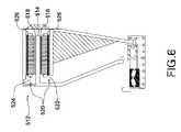
- FIG. 5illustrates a sectional view of a portion of a ship 510 comprising an exemplary double-sided ship propulsion motor 512 , a propeller 530 , a mounting and bearing assembly 532 , and a frame assembly 528 .
- FIG. 6illustrates a sectional view of the exemplary motor of FIG.
- the ship propulsion motor 512comprises at least one double-sided rotor 514 with an inner rotor side 516 and an outer rotor side 518 and at least one stator 520 with an inner stator core 522 and an outer stator core 524 , wherein the at least one double-sided rotor is concentrically disposed between the inner stator core and the outer stator core of the ship propulsion motor.
- FIG. 6further illustrates at least one cooling channel 526 for cooling the inner stator core and the outer stator core. In a typical ship propulsion embodiment, cooling channel 526 uses liquid for cooling the stator core.
- Cooling channel 526typically comprises a material selected from a group consisting of aluminum, copper, stainless steel and any combination thereof and may use any other material commonly used for cooling of electric machines.
- a heat exchanger(not shown) may be used to transfer the heat absorbed in the cooling liquid to the ambient air.
- Such cooling channels of FIG. 6can also be used in the wind turbine embodiments.
- a medium speed electrical machine with a gear boxmay be used for motoring and generating applications.
- a medium speed generatoris one that rotates with a speed between approximately 150 and 1000 rpm.
- a medium speed generator connected to a gear box with a gear ratio of approximately 10:1offers potential for wind generators.
- FIG. 7illustrates a diagrammatic view of an exemplary electrical machine 700 with the double-sided generator as described in the different embodiments for wind turbine hereinabove, along with a gear box 710 .
- the diameter of the generator 712matches the diameter of the gear box 710 .
- an optimally sized generator diameter for a megawatt wind generatorwould be significantly larger that the diameter of the gear box.
- the optimal outside diameter of a 2.5 MW wind generator attached to a 8:1 gear boxis 2.7 meters, while the 8:1 gear box diameter is less than 2 meters.
Landscapes
- Engineering & Computer Science (AREA)
- Power Engineering (AREA)
- Life Sciences & Earth Sciences (AREA)
- Sustainable Energy (AREA)
- Sustainable Development (AREA)
- Mechanical Engineering (AREA)
- Chemical & Material Sciences (AREA)
- Combustion & Propulsion (AREA)
- General Engineering & Computer Science (AREA)
- Thermal Sciences (AREA)
- Physics & Mathematics (AREA)
- Motor Or Generator Cooling System (AREA)
- Connection Of Motors, Electrical Generators, Mechanical Devices, And The Like (AREA)
- Iron Core Of Rotating Electric Machines (AREA)
Abstract
Description
Claims (28)
Priority Applications (6)
| Application Number | Priority Date | Filing Date | Title |
|---|---|---|---|
| US10/882,911US7154191B2 (en) | 2004-06-30 | 2004-06-30 | Electrical machine with double-sided rotor |
| DK05254010.1TDK1612415T3 (en) | 2004-06-30 | 2005-06-28 | Electric machine with double-sided rotor |
| EP05254010.1AEP1612415B1 (en) | 2004-06-30 | 2005-06-28 | Electrical machine with double-sided rotor |
| CN2005100822651ACN1716734B (en) | 2004-06-30 | 2005-06-30 | Electrical machine with double-sided rotor |
| US11/559,505US7830063B2 (en) | 2004-06-30 | 2006-11-14 | Electrical machine with double-sided rotor |
| US12/199,851US20080315698A1 (en) | 2004-06-30 | 2008-08-28 | Motor apparatus and method |
Applications Claiming Priority (1)
| Application Number | Priority Date | Filing Date | Title |
|---|---|---|---|
| US10/882,911US7154191B2 (en) | 2004-06-30 | 2004-06-30 | Electrical machine with double-sided rotor |
Related Parent Applications (1)
| Application Number | Title | Priority Date | Filing Date |
|---|---|---|---|
| US11/559,506Continuation-In-PartUS7839048B2 (en) | 2004-09-27 | 2006-11-14 | Electrical machine with double-sided stator |
Related Child Applications (1)
| Application Number | Title | Priority Date | Filing Date |
|---|---|---|---|
| US11/559,505Continuation-In-PartUS7830063B2 (en) | 2004-06-30 | 2006-11-14 | Electrical machine with double-sided rotor |
Publications (2)
| Publication Number | Publication Date |
|---|---|
| US20060001269A1 US20060001269A1 (en) | 2006-01-05 |
| US7154191B2true US7154191B2 (en) | 2006-12-26 |
Family
ID=34941770
Family Applications (2)
| Application Number | Title | Priority Date | Filing Date |
|---|---|---|---|
| US10/882,911Expired - Fee RelatedUS7154191B2 (en) | 2004-06-30 | 2004-06-30 | Electrical machine with double-sided rotor |
| US11/559,505Expired - Fee RelatedUS7830063B2 (en) | 2004-06-30 | 2006-11-14 | Electrical machine with double-sided rotor |
Family Applications After (1)
| Application Number | Title | Priority Date | Filing Date |
|---|---|---|---|
| US11/559,505Expired - Fee RelatedUS7830063B2 (en) | 2004-06-30 | 2006-11-14 | Electrical machine with double-sided rotor |
Country Status (4)
| Country | Link |
|---|---|
| US (2) | US7154191B2 (en) |
| EP (1) | EP1612415B1 (en) |
| CN (1) | CN1716734B (en) |
| DK (1) | DK1612415T3 (en) |
Cited By (76)
| Publication number | Priority date | Publication date | Assignee | Title |
|---|---|---|---|---|
| US20060138780A1 (en)* | 2002-08-08 | 2006-06-29 | Peter Flamang | Modular wind turbine transmission |
| US20070024060A1 (en)* | 2005-07-26 | 2007-02-01 | Bacon C R | Wind wheel and electricity generator using same |
| US20070024132A1 (en)* | 2005-07-29 | 2007-02-01 | Salamah Samir A | Methods and apparatus for cooling wind turbine generators |
| US20070090711A1 (en)* | 2005-10-24 | 2007-04-26 | General Electric Company | Method and apparatus for assembling a permanent magnet pole assembly |
| US20070103027A1 (en)* | 2004-09-27 | 2007-05-10 | Jansen Patrick L | Electrical machine with double-sided lamination stack |
| US20070108865A1 (en)* | 2004-09-27 | 2007-05-17 | Jansen Patrick L | Electrical machine with double-sided stator |
| US20070222223A1 (en)* | 2006-03-22 | 2007-09-27 | General Electric Company | Wind turbine generators having wind assisted cooling systems and cooling methods |
| US20070281558A1 (en)* | 2004-06-30 | 2007-12-06 | Jansen Patrick L | Electrical machine with double-sided rotor |
| US20070296299A1 (en)* | 2006-06-27 | 2007-12-27 | Ronghai Qu | Electrical machine with improved windings |
| US20080088135A1 (en)* | 2005-04-11 | 2008-04-17 | Novo Vidal Maria E | Electric power generating system using ring-shaped generators |
| US7391128B2 (en)* | 2004-12-30 | 2008-06-24 | Rozlev Corp., Llc | Wind generator system using attractive magnetic forces to reduce the load on the bearings |
| US20080174194A1 (en)* | 2006-12-07 | 2008-07-24 | General Electric Company | Double-Sided Starter/Generator for Aircrafts |
| US20080214797A1 (en)* | 2006-08-28 | 2008-09-04 | Sang Hyun Park | Preparation method of radioisotope labeling compound using carbon nanotube |
| US20080238236A1 (en)* | 2007-03-27 | 2008-10-02 | General Electric Company | Switched reluctance machine |
| US20080279686A1 (en)* | 2006-01-25 | 2008-11-13 | Jens Demtroder | Wind Turbine Comprising At Least One Gearbox And An Epicyclic Gearbox |
| US20080296994A1 (en)* | 2007-05-31 | 2008-12-04 | General Electric Company | Synchronous reluctance machine |
| US20080315594A1 (en)* | 2001-09-13 | 2008-12-25 | High Technology Investments, Bv | Wind power generator and bearing structure therefor |
| US20090045628A1 (en)* | 2006-03-25 | 2009-02-19 | William Erdman | Thermal management system for wind turbine |
| US20090058094A1 (en)* | 2007-08-27 | 2009-03-05 | General Electric Company | Integrated Medium-Speed Geared Drive Train |
| US20090072645A1 (en)* | 2007-09-13 | 2009-03-19 | Eric Stephane Quere | Composite electromechanical machines with gear mechanism |
| US20090115295A1 (en)* | 2007-10-08 | 2009-05-07 | Snecma | Turbojet having an electricity generator arranged in its fan |
| US20090149999A1 (en)* | 2007-12-11 | 2009-06-11 | Simon Schramm | Gearbox Noise Reduction By Electrical Drive Control |
| US20090309442A1 (en)* | 2008-06-12 | 2009-12-17 | General Electric Company | High torque density electrical machine |
| DE102008029377A1 (en) | 2008-06-20 | 2009-12-24 | Siemens Aktiengesellschaft | Device for a wind or hydroelectric power plant for generating electrical energy |
| US20100026010A1 (en)* | 2006-12-22 | 2010-02-04 | High Technology Investments B.V. | Multiple generator wind turbine |
| US20100032961A1 (en)* | 2007-10-23 | 2010-02-11 | Mitsubishi Heavy Industries, Ltd. | Wind turbine generator |
| US20100045047A1 (en)* | 2008-08-20 | 2010-02-25 | Henrik Stiesdal | Wind Turbine |
| US20100052323A1 (en)* | 2008-09-03 | 2010-03-04 | Parag Vyas | Magnetically geared generator |
| US20100061853A1 (en)* | 2008-09-11 | 2010-03-11 | General Electric Company | System for heating and cooling wind turbine components |
| US20100133854A1 (en)* | 2009-01-16 | 2010-06-03 | General Electric Company | Compact geared drive train |
| US20100264661A1 (en)* | 2009-04-20 | 2010-10-21 | Barber Gerald L | Electrical generator for wind turbine |
| US20100264667A1 (en)* | 2009-04-20 | 2010-10-21 | Barber Gerald L | Electrical Generator for Wind Turbine |
| US7936102B2 (en) | 2005-11-29 | 2011-05-03 | Wilic S.Ar.L | Magnet holder for permanent magnet rotors of rotating machines |
| US7946591B2 (en) | 2005-09-21 | 2011-05-24 | Wilic S.Ar.L. | Combined labyrinth seal and screw-type gasket bearing sealing arrangement |
| US20110140451A1 (en)* | 2009-12-16 | 2011-06-16 | Clear Path Energy, Llc | Axial Gap Rotating Electrical Machine |
| US20110142649A1 (en)* | 2010-09-28 | 2011-06-16 | General Electric Company | Compact geared drive train |
| US20110148119A1 (en)* | 2009-01-14 | 2011-06-23 | Amsc Windtec Gmbh | Generator, nacelle, and mounting method of a nacelle of a wind energy converter |
| US20110291415A1 (en)* | 2008-12-23 | 2011-12-01 | Michiel Eduard Cornelis Damen | Wind turbine and method for monitoring the gap length between a rotor and a stator of the wind turbine generator |
| US20120025537A1 (en)* | 2009-01-30 | 2012-02-02 | Vestas Wind Systems A/S | Wind turbine nacelle with cooler top |
| US8120198B2 (en) | 2008-07-23 | 2012-02-21 | Wilic S.Ar.L. | Wind power turbine |
| US8143738B2 (en) | 2008-08-06 | 2012-03-27 | Infinite Wind Energy LLC | Hyper-surface wind generator |
| US8272822B2 (en) | 2009-01-30 | 2012-09-25 | Wilic S.Ar.L. | Wind power turbine blade packing and packing method |
| US8274170B2 (en) | 2009-04-09 | 2012-09-25 | Willic S.A.R.L. | Wind power turbine including a cable bundle guide device |
| US8310122B2 (en) | 2005-11-29 | 2012-11-13 | Wilic S.A.R.L. | Core plate stack assembly for permanent magnet rotor or rotating machines |
| US8319362B2 (en) | 2008-11-12 | 2012-11-27 | Wilic S.Ar.L. | Wind power turbine with a cooling system |
| US8358189B2 (en) | 2009-08-07 | 2013-01-22 | Willic S.Ar.L. | Method and apparatus for activating an electric machine, and electric machine |
| US20130020893A1 (en)* | 2011-01-19 | 2013-01-24 | Converteam Technology Ltd. | Electrical Machines |
| US8410623B2 (en) | 2009-06-10 | 2013-04-02 | Wilic S. AR. L. | Wind power electricity generating system and relative control method |
| US20130088103A1 (en)* | 2011-10-05 | 2013-04-11 | Industrias Metalurgicas Pescarmona S.A.I.C. Y F. | Synchronic Wind Turbine Generator |
| US20130126669A1 (en)* | 2010-07-30 | 2013-05-23 | Siemens Aktiengesellschaft | Electric drive device for an aircraft |
| US20130161958A1 (en)* | 2011-05-20 | 2013-06-27 | Guodian United Power Technology Co., Ltd | Dual Stator Permanent Magnet Direct-drive Wind Power Generator with Stationary Shaft Support |
| US8492919B2 (en)* | 2008-06-19 | 2013-07-23 | Wilic S.Ar.L. | Wind power generator equipped with a cooling system |
| US8536726B2 (en) | 2010-09-17 | 2013-09-17 | Vestas Wind Systems A/S | Electrical machines, wind turbines, and methods for operating an electrical machine |
| US8541902B2 (en) | 2010-02-04 | 2013-09-24 | Wilic S.Ar.L. | Wind power turbine electric generator cooling system and method and wind power turbine comprising such a cooling system |
| US8568099B2 (en) | 2010-12-17 | 2013-10-29 | Vestas Wind Systems A/S | Apparatus for harvesting energy from a gearbox to power an electrical device and related methods |
| US8618689B2 (en) | 2009-11-23 | 2013-12-31 | Wilic S.Ar.L. | Wind power turbine for generating electric energy |
| US8659867B2 (en) | 2009-04-29 | 2014-02-25 | Wilic S.A.R.L. | Wind power system for generating electric energy |
| US8669685B2 (en) | 2008-11-13 | 2014-03-11 | Wilic S.Ar.L. | Wind power turbine for producing electric energy |
| US8723402B2 (en) | 2012-07-30 | 2014-05-13 | Boudler Wind Power, Inc. | Structure for an electromagnetic machine having compression and tension members |
| US8736133B1 (en) | 2013-03-14 | 2014-05-27 | Boulder Wind Power, Inc. | Methods and apparatus for overlapping windings |
| US8823241B2 (en) | 2009-01-16 | 2014-09-02 | Boulder Wind Power, Inc. | Segmented stator for an axial field device |
| US8876483B2 (en) | 2010-01-14 | 2014-11-04 | Neptco, Inc. | Wind turbine rotor blade components and methods of making same |
| US8937397B2 (en) | 2010-03-30 | 2015-01-20 | Wilic S.A.R.L. | Wind power turbine and method of removing a bearing from a wind power turbine |
| US8937398B2 (en) | 2011-03-10 | 2015-01-20 | Wilic S.Ar.L. | Wind turbine rotary electric machine |
| US8941255B2 (en) | 2011-08-26 | 2015-01-27 | D-Cube Wind Technologies, Llc | Free floating multiple stator arrangement generator for direct drive wind turbine and methods |
| US8957555B2 (en) | 2011-03-10 | 2015-02-17 | Wilic S.Ar.L. | Wind turbine rotary electric machine |
| US8975770B2 (en) | 2010-04-22 | 2015-03-10 | Wilic S.Ar.L. | Wind power turbine electric generator and wind power turbine equipped with an electric generator |
| US9006918B2 (en) | 2011-03-10 | 2015-04-14 | Wilic S.A.R.L. | Wind turbine |
| US20150188367A1 (en)* | 2013-12-28 | 2015-07-02 | Google Inc. | Electrically-Isolated and Liquid-Cooled Rotor and Stator Assemblies |
| US9154024B2 (en) | 2010-06-02 | 2015-10-06 | Boulder Wind Power, Inc. | Systems and methods for improved direct drive generators |
| US9270150B2 (en) | 2009-12-16 | 2016-02-23 | Clear Path Energy, Llc | Axial gap rotating electrical machine |
| US10137542B2 (en) | 2010-01-14 | 2018-11-27 | Senvion Gmbh | Wind turbine rotor blade components and machine for making same |
| US10177620B2 (en) | 2014-05-05 | 2019-01-08 | Boulder Wind Power, Inc. | Methods and apparatus for segmenting a machine |
| US20200266681A1 (en)* | 2019-02-20 | 2020-08-20 | Mitsubishi Heavy Industries, Ltd. | Rotary electric machine, generator, and wind turbine power generation facility |
| US11661646B2 (en) | 2021-04-21 | 2023-05-30 | General Electric Comapny | Dual phase magnetic material component and method of its formation |
| US11926880B2 (en) | 2021-04-21 | 2024-03-12 | General Electric Company | Fabrication method for a component having magnetic and non-magnetic dual phases |
Families Citing this family (37)
| Publication number | Priority date | Publication date | Assignee | Title |
|---|---|---|---|---|
| ITBZ20040047A1 (en) | 2004-09-20 | 2004-12-20 | High Technology Invest Bv | ELECTRIC GENERATOR / MOTOR, IN PARTICULAR FOR USE IN WIND PLANTS, ROPE OR HYDRAULIC PLANTS. |
| US7345376B2 (en)* | 2004-11-30 | 2008-03-18 | Distributed Energy Systems Corporation | Passively cooled direct drive wind turbine |
| EP1759987B1 (en)* | 2005-08-30 | 2011-03-30 | Torqeedo GmbH | Electric boat drive |
| KR100695012B1 (en)* | 2006-03-24 | 2007-03-14 | 유니슨 주식회사 | Wind generator |
| ES2318963B1 (en)* | 2006-05-30 | 2010-02-04 | GAMESA INNOVATION & TECHNOLOGY, S.L. | USE OF ORIENTED GRAIN LAMINATION IN A WIND TURBINE GENERATOR. |
| US7569955B2 (en)* | 2006-06-19 | 2009-08-04 | Thermal Motor Innovations, Llc | Electric motor with heat pipes |
| US8134260B2 (en)* | 2006-06-19 | 2012-03-13 | Hpev, Inc. | Electric motor with heat pipes |
| US8283818B2 (en) | 2006-06-19 | 2012-10-09 | Hpev, Inc. | Electric motor with heat pipes |
| RU2331792C2 (en)* | 2006-09-19 | 2008-08-20 | Анатолий Михайлович Русаков | Inverted electromagnetic wind generator |
| EP2063114A1 (en)* | 2007-11-26 | 2009-05-27 | Siemens Aktiengesellschaft | Wind turbine |
| US20090167023A1 (en)* | 2007-12-27 | 2009-07-02 | Jacob Johannes Nies | Forward leaning tower top section |
| US8148858B2 (en) | 2008-08-06 | 2012-04-03 | Hpev, Inc. | Totally enclosed heat pipe cooled motor |
| CN102301134B (en) | 2009-01-30 | 2014-09-24 | 维斯塔斯风力系统集团公司 | Wind turbine nacelle with cooler on top |
| US9039368B2 (en) | 2009-01-30 | 2015-05-26 | Vestas Wind Systems A/S | Wind turbine nacelle with cooler top |
| ES2648243T3 (en) | 2009-01-30 | 2017-12-29 | Vestas Wind Systems A/S | Wind turbine gondola with cooling top |
| DE102009008437A1 (en)* | 2009-02-11 | 2010-08-12 | Vensys Energy Ag | Machine carrier for receiving a rotor / generator assembly of a gearless wind turbine |
| CN101520023B (en)* | 2009-03-26 | 2011-09-07 | 徐剑雄 | Variable propeller pitch wind wheel of wind powered generator |
| BR112012016868A2 (en)* | 2010-01-11 | 2018-05-15 | Siemens Ag | Direct drive wind turbine with a cooling system. |
| EP2565450A4 (en)* | 2010-04-28 | 2014-07-09 | Mitsubishi Heavy Ind Ltd | Direct drive wind turbine and bearing structure |
| CN102624147B (en)* | 2011-01-26 | 2016-03-23 | 阿尔斯通技术有限公司 | Improve the method in power plant |
| CN102142750B (en)* | 2011-02-23 | 2012-08-08 | 中科盛创(青岛)电气有限公司 | Nested squirrel cage type direct-drive wind driven generator structure |
| EP2748915B1 (en)* | 2011-09-13 | 2018-03-07 | Rolls-Royce Aktiebolag | A method of and a device for protecting a motor in a pod against shaft bending shocks |
| EP2578872B1 (en) | 2011-10-04 | 2018-01-03 | Siemens Aktiengesellschaft | Generator |
| US9502931B2 (en) | 2012-03-23 | 2016-11-22 | Asmo Co., Ltd. | Brushless motor |
| EP2728712A1 (en)* | 2012-10-31 | 2014-05-07 | Openhydro IP Limited | A power generator for a hydro turbine |
| EP2736154A1 (en)* | 2012-11-21 | 2014-05-28 | Siemens Aktiengesellschaft | Dual stator permanent magnet generator for a wind turbine |
| US10170959B2 (en)* | 2013-03-13 | 2019-01-01 | Regal Beloit America, Inc. | Electrical machines and methods of assembling the same |
| DE102013214087A1 (en)* | 2013-07-18 | 2015-01-22 | Siemens Aktiengesellschaft | Electric nacelle drive for a ship |
| EP3076529A1 (en)* | 2015-04-01 | 2016-10-05 | Siemens Aktiengesellschaft | Electric rotary machine having laterally magnetised lenticular magnets |
| US10424117B2 (en)* | 2015-12-02 | 2019-09-24 | Seiko Epson Corporation | Controlling a display of a head-mounted display device |
| EP3211767B1 (en)* | 2016-02-26 | 2023-05-03 | Siemens Aktiengesellschaft | Electric machine with bell-shaped rotor |
| US20180054093A1 (en)* | 2016-08-17 | 2018-02-22 | Arnold Yoonho Lee | Electric generator that generates electrical energy by magnetic induction |
| RU2673334C2 (en)* | 2017-04-07 | 2018-11-26 | Общество С Ограниченной Ответственностью "Русский Ветер" (Ооо "Русский Ветер") | Generator with direct drive of wind power plant for harsh climate regions |
| US10715019B2 (en) | 2018-05-18 | 2020-07-14 | Kohler Co. | Dual axis motor |
| CN109412339B (en)* | 2018-09-06 | 2020-04-28 | 新疆金风科技股份有限公司 | Motors and Wind Turbines |
| CN109474113B (en) | 2018-09-06 | 2020-06-23 | 新疆金风科技股份有限公司 | Motor and wind generating set |
| CN111749859A (en)* | 2019-03-26 | 2020-10-09 | 北京金风科创风电设备有限公司 | Wind power generating set, cooling system thereof, and control method of cooling system |
Citations (51)
| Publication number | Priority date | Publication date | Assignee | Title |
|---|---|---|---|---|
| US1661135A (en) | 1922-04-17 | 1928-02-28 | Allis Chalmers Mfg Co | Method of manufacturing dynamo-electric machines |
| US3023330A (en) | 1960-04-08 | 1962-02-27 | Casner Patents Inc | Axial air-gap dynamoelectric machine |
| US3789252A (en) | 1971-02-24 | 1974-01-29 | Bbc Brown Boveri & Cie | Two-part stator for large rotating electrical machines |
| JPS5315502A (en) | 1976-07-28 | 1978-02-13 | Hitachi Ltd | Rotary electric machine |
| US4088352A (en)* | 1975-02-14 | 1978-05-09 | Alberto Kling | Wind-driven power plant |
| US4187441A (en) | 1977-03-23 | 1980-02-05 | General Electric Company | High power density brushless dc motor |
| JPS5653557A (en) | 1979-10-09 | 1981-05-13 | Toshiba Corp | Liquid-cooled electric rotary machine |
| JPS5674075A (en) | 1979-11-19 | 1981-06-19 | Nippon Yusoki Co Ltd | Yokeless dc motor |
| JPS56107767A (en) | 1980-01-25 | 1981-08-26 | Hitachi Ltd | Cylindrical water turbine generator |
| US4517484A (en) | 1982-02-18 | 1985-05-14 | Ateliers De Constructions Electriques De Charleroi (Acec) | Double gap electric generating machines |
| US4720640A (en) | 1985-09-23 | 1988-01-19 | Turbostar, Inc. | Fluid powered electrical generator |
| US4761590A (en) | 1987-07-20 | 1988-08-02 | Polestar Magnetronics Inc. | Electric motor |
| US4866321A (en) | 1985-03-26 | 1989-09-12 | William C. Lamb | Brushless electrical machine for use as motor or generator |
| US4900965A (en) | 1988-09-28 | 1990-02-13 | Fisher Technology, Inc. | Lightweight high power electromotive device |
| US5004944A (en) | 1985-12-23 | 1991-04-02 | Unique Mobility, Inc. | Lightweight high power electromagnetic transducer |
| DE4023791A1 (en) | 1990-07-26 | 1992-01-30 | Siemens Ag | ELECTRICAL MACHINE WITH AN INNER AND EXTERNAL RUNNER |
| US5315159A (en)* | 1989-10-12 | 1994-05-24 | Holec Projects B.V. | Wind turbine |
| US5331244A (en) | 1990-12-24 | 1994-07-19 | Orto Holding | Permanent magnet DC machine having meander-like stator windings for producing high torque without excessive heating |
| DE4402184C2 (en) | 1994-01-26 | 1995-11-23 | Friedrich Prof Dr Ing Klinger | Multi-pole synchronous generator for gearless horizontal-axis wind turbines with nominal powers of up to several megawatts |
| DE19636591A1 (en) | 1996-09-10 | 1998-03-12 | Friedrich Prof Dr Ing Klinger | Permanent magnet sync generator for direct wind-power energy converter |
| US5731649A (en)* | 1996-12-27 | 1998-03-24 | Caama+E,Otl N+Ee O; Ramon A. | Electric motor or generator |
| DE19643362A1 (en) | 1996-10-08 | 1998-04-23 | Miroslaw Janowicz | Wind or hydro generator |
| US5751089A (en)* | 1992-01-29 | 1998-05-12 | Stridsberg Innovation Ab | Brushless DC motors/generators |
| DE19704652C1 (en) | 1997-02-07 | 1998-07-30 | Anton Knestel | Use of a ring winding in electrical induction machines |
| WO1999039426A1 (en) | 1998-01-30 | 1999-08-05 | Schroedl Manfred | Electric machine |
| US6177746B1 (en) | 1999-10-21 | 2001-01-23 | Christopher N. Tupper | Low inductance electrical machine |
| WO2001006623A1 (en) | 1999-04-23 | 2001-01-25 | Aerpac Holding B.V. | Generator |
| WO2001021956A1 (en) | 1999-09-24 | 2001-03-29 | Lagerwey Windturbine B.V. | Wind power generator |
| US6285090B1 (en)* | 1997-03-10 | 2001-09-04 | Jeumont Industrie | Low-speed directly driven wind turbine |
| US20020047418A1 (en) | 2000-09-14 | 2002-04-25 | Masahiro Seguchi | Compact and reliable structure of multi-rotor synchronous machine |
| WO2002057624A1 (en) | 2001-01-19 | 2002-07-25 | Aloys Wobben | Wind energy unit comprising a hollow shaft for rotor hub and generator |
| US6462457B2 (en) | 2000-12-27 | 2002-10-08 | General Electric Company | Power generator |
| FR2823178A1 (en) | 2001-04-10 | 2002-10-11 | Technicatome | Under hull suspended ship electric propulsion unit, has reinforced nacelle and hydrostatic or hydrodynamic bearings |
| US6590312B1 (en) | 1999-11-18 | 2003-07-08 | Denso Corporation | Rotary electric machine having a permanent magnet stator and permanent magnet rotor |
| WO2003078834A1 (en)* | 2002-03-15 | 2003-09-25 | Michael Kreitel | Current generator |
| US20030193253A1 (en) | 2002-04-01 | 2003-10-16 | Nissan Motor Co., Ltd. | Driving method and system for electrical rotating machine having two rotors using compound current |
| US20030236036A1 (en) | 2000-01-28 | 2003-12-25 | Jukka Varis | Motor unit for a ship |
| EP1375913A1 (en) | 2002-06-28 | 2004-01-02 | High Technology Investments B.V. | Wind turbine with discoid generator |
| EP1394406A2 (en) | 2002-08-28 | 2004-03-03 | Friedrich Prof. Dr.-Ing. Klinger | Gearless wind turbine with multiple generator |
| US20040041409A1 (en) | 2002-08-30 | 2004-03-04 | Gabrys Christopher W. | Wind turbine |
| US6720688B1 (en)* | 1999-02-12 | 2004-04-13 | Helmut Schiller | Electric machine |
| WO2004040740A1 (en)* | 2002-10-29 | 2004-05-13 | Siemens Aktiengesellschaft | Dual-supply induction machine comprising a second counter-rotating rotor |
| US6744504B2 (en) | 2000-09-08 | 2004-06-01 | Shimadzu Corporation | Light analyzer |
| US20040119373A1 (en) | 2002-04-01 | 2004-06-24 | Kan Akatsu | Electrical rotating machine having two rotors driven by means of compound current |
| US6762525B1 (en) | 2002-04-30 | 2004-07-13 | Wavecrest Laboratories, Llc | Cascaded rotary electric motors having axial and radial air gaps |
| US20040135461A1 (en) | 2002-04-01 | 2004-07-15 | Shuzo Miyake | Stator mounting for a double rotor electric motor |
| US6774527B2 (en) | 2001-09-07 | 2004-08-10 | Nissan Motor Co., Ltd. | Two rotor single stator type electric motor |
| US6794781B2 (en)* | 2002-04-13 | 2004-09-21 | Rolls-Royce Plc | Compact electrical machine |
| EP1465326A2 (en) | 2003-04-04 | 2004-10-06 | Nissan Motor Company, Limited | Stator of two rotor single stator type electric motor |
| US20040239199A1 (en) | 2003-05-30 | 2004-12-02 | Wisconsin Alumni Research Foundation | Dual-rotor, radial-flux, toroidally-wound, permanent-magnet machine |
| GB2417140A (en)* | 2004-08-09 | 2006-02-15 | Alstom | Superconducting machine with stator between two superconducting rotors |
Family Cites Families (16)
| Publication number | Priority date | Publication date | Assignee | Title |
|---|---|---|---|---|
| US3148294A (en)* | 1961-01-25 | 1964-09-08 | Eaton Mfg Co | Fluid-cooled rotary electrical apparatus |
| DE3629872A1 (en)* | 1986-09-02 | 1988-03-10 | Licentia Gmbh | Wind-power installation for generating electrical energy |
| US5081388A (en)* | 1990-07-24 | 1992-01-14 | Chen Shew Nen | Magnetic induction motor |
| US5334898A (en)* | 1991-09-30 | 1994-08-02 | Dymytro Skybyk | Polyphase brushless DC and AC synchronous machines |
| US5212419A (en)* | 1992-01-10 | 1993-05-18 | Fisher Electric Motor Technology, Inc. | Lightweight high power electromotive device |
| US5625241A (en)* | 1994-07-28 | 1997-04-29 | Energy Research Corporation | Carousel electric generator |
| US5783893A (en)* | 1995-10-20 | 1998-07-21 | Newport News Shipbuilding And Dry Dock Company | Multiple stator, single shaft electric machine |
| US5977684A (en)* | 1998-06-12 | 1999-11-02 | Lin; Ted T. | Rotating machine configurable as true DC generator or motor |
| DE19838378A1 (en)* | 1998-08-24 | 2000-03-02 | Magnet Motor Gmbh | Electrical machine with permanent magnets |
| FR2796671B1 (en)* | 1999-07-22 | 2002-04-19 | Jeumont Ind | DEVICE FOR CAPTURING WIND ENERGY AND PRODUCING ELECTRICAL ENERGY AND METHOD FOR OPTIMIZING ENERGY PRODUCTION |
| US6464457B1 (en)* | 2001-06-21 | 2002-10-15 | General Electric Company | Turbine leaf seal mounting with headless pins |
| US6861766B2 (en)* | 2001-12-03 | 2005-03-01 | Peter Rembert | Hydro-electric generating system |
| US6794783B2 (en)* | 2003-01-10 | 2004-09-21 | Sunyen Co., Ltd. | Flat rotary electric generator |
| US7154193B2 (en)* | 2004-09-27 | 2006-12-26 | General Electric Company | Electrical machine with double-sided stator |
| US7154192B2 (en)* | 2004-09-27 | 2006-12-26 | General Electric Company | Electrical machine with double-sided lamination stack |
| US7154191B2 (en)* | 2004-06-30 | 2006-12-26 | General Electric Company | Electrical machine with double-sided rotor |
- 2004
- 2004-06-30USUS10/882,911patent/US7154191B2/ennot_activeExpired - Fee Related
- 2005
- 2005-06-28EPEP05254010.1Apatent/EP1612415B1/ennot_activeExpired - Lifetime
- 2005-06-28DKDK05254010.1Tpatent/DK1612415T3/enactive
- 2005-06-30CNCN2005100822651Apatent/CN1716734B/ennot_activeExpired - Fee Related
- 2006
- 2006-11-14USUS11/559,505patent/US7830063B2/ennot_activeExpired - Fee Related
Patent Citations (54)
| Publication number | Priority date | Publication date | Assignee | Title |
|---|---|---|---|---|
| US1661135A (en) | 1922-04-17 | 1928-02-28 | Allis Chalmers Mfg Co | Method of manufacturing dynamo-electric machines |
| US3023330A (en) | 1960-04-08 | 1962-02-27 | Casner Patents Inc | Axial air-gap dynamoelectric machine |
| US3789252A (en) | 1971-02-24 | 1974-01-29 | Bbc Brown Boveri & Cie | Two-part stator for large rotating electrical machines |
| US4088352A (en)* | 1975-02-14 | 1978-05-09 | Alberto Kling | Wind-driven power plant |
| JPS5315502A (en) | 1976-07-28 | 1978-02-13 | Hitachi Ltd | Rotary electric machine |
| US4187441A (en) | 1977-03-23 | 1980-02-05 | General Electric Company | High power density brushless dc motor |
| JPS5653557A (en) | 1979-10-09 | 1981-05-13 | Toshiba Corp | Liquid-cooled electric rotary machine |
| JPS5674075A (en) | 1979-11-19 | 1981-06-19 | Nippon Yusoki Co Ltd | Yokeless dc motor |
| JPS56107767A (en) | 1980-01-25 | 1981-08-26 | Hitachi Ltd | Cylindrical water turbine generator |
| US4517484A (en) | 1982-02-18 | 1985-05-14 | Ateliers De Constructions Electriques De Charleroi (Acec) | Double gap electric generating machines |
| US4866321A (en) | 1985-03-26 | 1989-09-12 | William C. Lamb | Brushless electrical machine for use as motor or generator |
| US4720640A (en) | 1985-09-23 | 1988-01-19 | Turbostar, Inc. | Fluid powered electrical generator |
| US5004944A (en) | 1985-12-23 | 1991-04-02 | Unique Mobility, Inc. | Lightweight high power electromagnetic transducer |
| US5311092A (en) | 1985-12-23 | 1994-05-10 | Unique Mobility, Inc. | Lightweight high power electromagnetic transducer |
| US4761590A (en) | 1987-07-20 | 1988-08-02 | Polestar Magnetronics Inc. | Electric motor |
| US4900965A (en) | 1988-09-28 | 1990-02-13 | Fisher Technology, Inc. | Lightweight high power electromotive device |
| US5315159A (en)* | 1989-10-12 | 1994-05-24 | Holec Projects B.V. | Wind turbine |
| DE4023791A1 (en) | 1990-07-26 | 1992-01-30 | Siemens Ag | ELECTRICAL MACHINE WITH AN INNER AND EXTERNAL RUNNER |
| US5331244A (en) | 1990-12-24 | 1994-07-19 | Orto Holding | Permanent magnet DC machine having meander-like stator windings for producing high torque without excessive heating |
| US5751089A (en)* | 1992-01-29 | 1998-05-12 | Stridsberg Innovation Ab | Brushless DC motors/generators |
| DE4402184C2 (en) | 1994-01-26 | 1995-11-23 | Friedrich Prof Dr Ing Klinger | Multi-pole synchronous generator for gearless horizontal-axis wind turbines with nominal powers of up to several megawatts |
| DE19636591A1 (en) | 1996-09-10 | 1998-03-12 | Friedrich Prof Dr Ing Klinger | Permanent magnet sync generator for direct wind-power energy converter |
| DE19643362A1 (en) | 1996-10-08 | 1998-04-23 | Miroslaw Janowicz | Wind or hydro generator |
| US5731649A (en)* | 1996-12-27 | 1998-03-24 | Caama+E,Otl N+Ee O; Ramon A. | Electric motor or generator |
| DE19704652C1 (en) | 1997-02-07 | 1998-07-30 | Anton Knestel | Use of a ring winding in electrical induction machines |
| US6285090B1 (en)* | 1997-03-10 | 2001-09-04 | Jeumont Industrie | Low-speed directly driven wind turbine |
| WO1999039426A1 (en) | 1998-01-30 | 1999-08-05 | Schroedl Manfred | Electric machine |
| US6720688B1 (en)* | 1999-02-12 | 2004-04-13 | Helmut Schiller | Electric machine |
| WO2001006623A1 (en) | 1999-04-23 | 2001-01-25 | Aerpac Holding B.V. | Generator |
| WO2001021956A1 (en) | 1999-09-24 | 2001-03-29 | Lagerwey Windturbine B.V. | Wind power generator |
| US6177746B1 (en) | 1999-10-21 | 2001-01-23 | Christopher N. Tupper | Low inductance electrical machine |
| US6590312B1 (en) | 1999-11-18 | 2003-07-08 | Denso Corporation | Rotary electric machine having a permanent magnet stator and permanent magnet rotor |
| US20030236036A1 (en) | 2000-01-28 | 2003-12-25 | Jukka Varis | Motor unit for a ship |
| US6744504B2 (en) | 2000-09-08 | 2004-06-01 | Shimadzu Corporation | Light analyzer |
| US20020047418A1 (en) | 2000-09-14 | 2002-04-25 | Masahiro Seguchi | Compact and reliable structure of multi-rotor synchronous machine |
| US6462457B2 (en) | 2000-12-27 | 2002-10-08 | General Electric Company | Power generator |
| WO2002057624A1 (en) | 2001-01-19 | 2002-07-25 | Aloys Wobben | Wind energy unit comprising a hollow shaft for rotor hub and generator |
| FR2823178A1 (en) | 2001-04-10 | 2002-10-11 | Technicatome | Under hull suspended ship electric propulsion unit, has reinforced nacelle and hydrostatic or hydrodynamic bearings |
| US6774527B2 (en) | 2001-09-07 | 2004-08-10 | Nissan Motor Co., Ltd. | Two rotor single stator type electric motor |
| WO2003078834A1 (en)* | 2002-03-15 | 2003-09-25 | Michael Kreitel | Current generator |
| US20040119373A1 (en) | 2002-04-01 | 2004-06-24 | Kan Akatsu | Electrical rotating machine having two rotors driven by means of compound current |
| US20040135461A1 (en) | 2002-04-01 | 2004-07-15 | Shuzo Miyake | Stator mounting for a double rotor electric motor |
| US20030193253A1 (en) | 2002-04-01 | 2003-10-16 | Nissan Motor Co., Ltd. | Driving method and system for electrical rotating machine having two rotors using compound current |
| US6794781B2 (en)* | 2002-04-13 | 2004-09-21 | Rolls-Royce Plc | Compact electrical machine |
| US6762525B1 (en) | 2002-04-30 | 2004-07-13 | Wavecrest Laboratories, Llc | Cascaded rotary electric motors having axial and radial air gaps |
| EP1375913A1 (en) | 2002-06-28 | 2004-01-02 | High Technology Investments B.V. | Wind turbine with discoid generator |
| EP1394406A2 (en) | 2002-08-28 | 2004-03-03 | Friedrich Prof. Dr.-Ing. Klinger | Gearless wind turbine with multiple generator |
| US20040041409A1 (en) | 2002-08-30 | 2004-03-04 | Gabrys Christopher W. | Wind turbine |
| US7042109B2 (en)* | 2002-08-30 | 2006-05-09 | Gabrys Christopher W | Wind turbine |
| WO2004040740A1 (en)* | 2002-10-29 | 2004-05-13 | Siemens Aktiengesellschaft | Dual-supply induction machine comprising a second counter-rotating rotor |
| EP1465326A2 (en) | 2003-04-04 | 2004-10-06 | Nissan Motor Company, Limited | Stator of two rotor single stator type electric motor |
| US20040195929A1 (en) | 2003-04-04 | 2004-10-07 | Nissan Motor Co., Ltd. | Stator of two rotor single stator type electric motor |
| US20040239199A1 (en) | 2003-05-30 | 2004-12-02 | Wisconsin Alumni Research Foundation | Dual-rotor, radial-flux, toroidally-wound, permanent-magnet machine |
| GB2417140A (en)* | 2004-08-09 | 2006-02-15 | Alstom | Superconducting machine with stator between two superconducting rotors |
Non-Patent Citations (9)
| Title |
|---|
| Edward Spooner, et al., "Modular, Permanent Magnet Wind-Turbine Generators", 1996 IEEE, pp. 497-502. |
| EPO Search Report dated Jan. 16, 2006. |
| EPO Search Report dated Jan. 20, 2006. |
| Office Action for U.S. Appl. No. 10/951,329 mailed Aug. 18, 2005. |
| Office Action for U.S. Appl. No. 10/951,329 mailed Dec. 22, 2005. |
| Ronghai Qu, "Dual-Rotor, Radial-Flux, Toroidally Wound, Permanent-Magnet Machines", 2003 IEEE Trans on Industry Applications, vol. 39, No. 6, pp. 1665-1673. |
| US Patent Application Entitled "Electrical Machine With Double-Sided Lamination Stack", U.S. Appl. No. 10/951,329 filed Sep. 27, 2004, By Patrick L. Jansen, et al. |
| US Patent Application Entitled "Electrical Machine With Double-Sided Stator", U.S. Appl. No. 10/951,335 filed Sep. 27, 2004, By Patrick L. Jansen, et al. |
| US Patent Application Entitled "Electrical Machines and Assemblies Including a Yokeless Stator With Modular Lamination Stacks", U.S. Appl. No. 11/014,137 filed Dec. 16, 2004. |
Cited By (131)
| Publication number | Priority date | Publication date | Assignee | Title |
|---|---|---|---|---|
| US20080315594A1 (en)* | 2001-09-13 | 2008-12-25 | High Technology Investments, Bv | Wind power generator and bearing structure therefor |
| US7893555B2 (en) | 2001-09-13 | 2011-02-22 | Wilic S.Ar.L. | Wind power current generator |
| US7687932B2 (en)* | 2001-09-13 | 2010-03-30 | High Technology Investments B.V. | Wind power generator and bearing structure therefor |
| US20060138780A1 (en)* | 2002-08-08 | 2006-06-29 | Peter Flamang | Modular wind turbine transmission |
| US7830063B2 (en) | 2004-06-30 | 2010-11-09 | General Electric Company | Electrical machine with double-sided rotor |
| US20070281558A1 (en)* | 2004-06-30 | 2007-12-06 | Jansen Patrick L | Electrical machine with double-sided rotor |
| US20070108865A1 (en)* | 2004-09-27 | 2007-05-17 | Jansen Patrick L | Electrical machine with double-sided stator |
| US20070103027A1 (en)* | 2004-09-27 | 2007-05-10 | Jansen Patrick L | Electrical machine with double-sided lamination stack |
| US7839048B2 (en) | 2004-09-27 | 2010-11-23 | General Electric Company | Electrical machine with double-sided stator |
| US7548008B2 (en) | 2004-09-27 | 2009-06-16 | General Electric Company | Electrical machine with double-sided lamination stack |
| US7391128B2 (en)* | 2004-12-30 | 2008-06-24 | Rozlev Corp., Llc | Wind generator system using attractive magnetic forces to reduce the load on the bearings |
| US20080088135A1 (en)* | 2005-04-11 | 2008-04-17 | Novo Vidal Maria E | Electric power generating system using ring-shaped generators |
| US7425772B2 (en)* | 2005-04-11 | 2008-09-16 | Maria Elena Novo Vidal | Electric power generating system using ring-shaped generators |
| US20070200350A1 (en)* | 2005-07-26 | 2007-08-30 | Bacon C R | Wind wheel and electricity generator using same |
| US7215038B2 (en)* | 2005-07-26 | 2007-05-08 | Bacon C Richard | Wind wheel and electricity generator using same |
| US7345377B2 (en)* | 2005-07-26 | 2008-03-18 | Bacon Group Llc | Wind wheel and electricity generator using same |
| US20070024060A1 (en)* | 2005-07-26 | 2007-02-01 | Bacon C R | Wind wheel and electricity generator using same |
| US7358624B2 (en)* | 2005-07-26 | 2008-04-15 | Bacon Group Llc | Wind wheel and electricity generator using same |
| US20070200349A1 (en)* | 2005-07-26 | 2007-08-30 | Bacon C R | Wind wheel and electricity generator using same |
| US7443066B2 (en)* | 2005-07-29 | 2008-10-28 | General Electric Company | Methods and apparatus for cooling wind turbine generators |
| US20070024132A1 (en)* | 2005-07-29 | 2007-02-01 | Salamah Samir A | Methods and apparatus for cooling wind turbine generators |
| US7946591B2 (en) | 2005-09-21 | 2011-05-24 | Wilic S.Ar.L. | Combined labyrinth seal and screw-type gasket bearing sealing arrangement |
| US20070090711A1 (en)* | 2005-10-24 | 2007-04-26 | General Electric Company | Method and apparatus for assembling a permanent magnet pole assembly |
| US7573168B2 (en)* | 2005-10-24 | 2009-08-11 | General Electric Company | Method and apparatus for assembling a permanent magnet pole assembly |
| US8310122B2 (en) | 2005-11-29 | 2012-11-13 | Wilic S.A.R.L. | Core plate stack assembly for permanent magnet rotor or rotating machines |
| US7936102B2 (en) | 2005-11-29 | 2011-05-03 | Wilic S.Ar.L | Magnet holder for permanent magnet rotors of rotating machines |
| US20080279686A1 (en)* | 2006-01-25 | 2008-11-13 | Jens Demtroder | Wind Turbine Comprising At Least One Gearbox And An Epicyclic Gearbox |
| US8393993B2 (en) | 2006-01-25 | 2013-03-12 | Vestas Wing Systems A/S | Wind turbine comprising at least one gearbox and an epicyclic gearbox |
| US20070222223A1 (en)* | 2006-03-22 | 2007-09-27 | General Electric Company | Wind turbine generators having wind assisted cooling systems and cooling methods |
| US7427814B2 (en)* | 2006-03-22 | 2008-09-23 | General Electric Company | Wind turbine generators having wind assisted cooling systems and cooling methods |
| US20090045628A1 (en)* | 2006-03-25 | 2009-02-19 | William Erdman | Thermal management system for wind turbine |
| US8058742B2 (en)* | 2006-03-25 | 2011-11-15 | Clipper Windpower, Inc. | Thermal management system for wind turbine |
| US20070296299A1 (en)* | 2006-06-27 | 2007-12-27 | Ronghai Qu | Electrical machine with improved windings |
| US7521835B2 (en)* | 2006-06-27 | 2009-04-21 | General Electric Company | Permanent magnet machine with windings having strand transposition |
| US20080214797A1 (en)* | 2006-08-28 | 2008-09-04 | Sang Hyun Park | Preparation method of radioisotope labeling compound using carbon nanotube |
| US8247538B2 (en) | 2006-08-28 | 2012-08-21 | Korea Atomic Energy Research Institute | Preparation method of radioisotope labeling compound using carbon nanotube |
| US7750521B2 (en)* | 2006-12-07 | 2010-07-06 | General Electric Company | Double-sided starter/generator for aircrafts |
| US20080174194A1 (en)* | 2006-12-07 | 2008-07-24 | General Electric Company | Double-Sided Starter/Generator for Aircrafts |
| US20100026010A1 (en)* | 2006-12-22 | 2010-02-04 | High Technology Investments B.V. | Multiple generator wind turbine |
| US20080238236A1 (en)* | 2007-03-27 | 2008-10-02 | General Electric Company | Switched reluctance machine |
| US7652404B2 (en) | 2007-05-31 | 2010-01-26 | General Electric Company | Synchronous reluctance machine |
| US20080296994A1 (en)* | 2007-05-31 | 2008-12-04 | General Electric Company | Synchronous reluctance machine |
| US20090058094A1 (en)* | 2007-08-27 | 2009-03-05 | General Electric Company | Integrated Medium-Speed Geared Drive Train |
| US7935020B2 (en) | 2007-08-27 | 2011-05-03 | General Electric Company | Integrated medium-speed geared drive train |
| US20090206692A1 (en)* | 2007-09-13 | 2009-08-20 | Eric Stephane Quere | Composite electromechanical machines with uniform magnets |
| US20090072645A1 (en)* | 2007-09-13 | 2009-03-19 | Eric Stephane Quere | Composite electromechanical machines with gear mechanism |
| US8288916B2 (en) | 2007-09-13 | 2012-10-16 | Eric Stephane Quere | Composite electromechanical machines with uniform magnets |
| US7956504B2 (en) | 2007-09-13 | 2011-06-07 | Eric Stephane Quere | Composite electromechanical machines with gear mechanism |
| US7952244B2 (en)* | 2007-10-08 | 2011-05-31 | Snecma | Turbojet having an electricity generator arranged in its fan |
| US20090115295A1 (en)* | 2007-10-08 | 2009-05-07 | Snecma | Turbojet having an electricity generator arranged in its fan |
| US8198749B2 (en)* | 2007-10-23 | 2012-06-12 | Mitsubishi Heavy Industries, Ltd. | Wind turbine generator |
| US20100032961A1 (en)* | 2007-10-23 | 2010-02-11 | Mitsubishi Heavy Industries, Ltd. | Wind turbine generator |
| US8532828B2 (en)* | 2007-12-11 | 2013-09-10 | General Electric Company | Gearbox noise reduction by electrical drive control |
| US20090149999A1 (en)* | 2007-12-11 | 2009-06-11 | Simon Schramm | Gearbox Noise Reduction By Electrical Drive Control |
| US9537362B2 (en) | 2008-06-12 | 2017-01-03 | General Electric Company | Electrical machine with improved stator flux pattern across a rotor for providing high torque density |
| US8847464B2 (en) | 2008-06-12 | 2014-09-30 | General Electric Company | Electrical machine with improved stator flux pattern across a rotor that permits higher torque density |
| US20090309442A1 (en)* | 2008-06-12 | 2009-12-17 | General Electric Company | High torque density electrical machine |
| US10505419B2 (en) | 2008-06-19 | 2019-12-10 | Windfin B.V. | Wind power generator equipped with a cooling system |
| US9312741B2 (en) | 2008-06-19 | 2016-04-12 | Windfin B.V. | Wind power generator equipped with a cooling system |
| US8492919B2 (en)* | 2008-06-19 | 2013-07-23 | Wilic S.Ar.L. | Wind power generator equipped with a cooling system |
| WO2009153187A3 (en)* | 2008-06-20 | 2010-08-05 | Siemens Aktiengesellschaft | Device for a wind or water power system for generating electrical energy |
| DE102008029377B4 (en)* | 2008-06-20 | 2010-09-30 | Siemens Aktiengesellschaft | Device for a wind or hydroelectric power plant for generating electrical energy |
| DE102008029377A1 (en) | 2008-06-20 | 2009-12-24 | Siemens Aktiengesellschaft | Device for a wind or hydroelectric power plant for generating electrical energy |
| US8120198B2 (en) | 2008-07-23 | 2012-02-21 | Wilic S.Ar.L. | Wind power turbine |
| US8143738B2 (en) | 2008-08-06 | 2012-03-27 | Infinite Wind Energy LLC | Hyper-surface wind generator |
| US8358028B2 (en)* | 2008-08-20 | 2013-01-22 | Siemens Aktiengesellschaft | Wind turbine |
| US20100045047A1 (en)* | 2008-08-20 | 2010-02-25 | Henrik Stiesdal | Wind Turbine |
| US20100052323A1 (en)* | 2008-09-03 | 2010-03-04 | Parag Vyas | Magnetically geared generator |
| US8299641B2 (en) | 2008-09-03 | 2012-10-30 | General Electric Company | Magnetically geared generator |
| US8047774B2 (en) | 2008-09-11 | 2011-11-01 | General Electric Company | System for heating and cooling wind turbine components |
| US20100061853A1 (en)* | 2008-09-11 | 2010-03-11 | General Electric Company | System for heating and cooling wind turbine components |
| US8319362B2 (en) | 2008-11-12 | 2012-11-27 | Wilic S.Ar.L. | Wind power turbine with a cooling system |
| US8669685B2 (en) | 2008-11-13 | 2014-03-11 | Wilic S.Ar.L. | Wind power turbine for producing electric energy |
| US20110291415A1 (en)* | 2008-12-23 | 2011-12-01 | Michiel Eduard Cornelis Damen | Wind turbine and method for monitoring the gap length between a rotor and a stator of the wind turbine generator |
| US8729722B2 (en)* | 2008-12-23 | 2014-05-20 | Xemc Darwind B.V. | Wind turbine and method for monitoring the gap length between a rotor and a stator of the wind turbine generator |
| US20110148119A1 (en)* | 2009-01-14 | 2011-06-23 | Amsc Windtec Gmbh | Generator, nacelle, and mounting method of a nacelle of a wind energy converter |
| US8154146B2 (en)* | 2009-01-14 | 2012-04-10 | Amsc Windtec Gmbh | Generator, nacelle, and mounting method of a nacelle of a wind energy converter |
| US8823241B2 (en) | 2009-01-16 | 2014-09-02 | Boulder Wind Power, Inc. | Segmented stator for an axial field device |
| US9762099B2 (en) | 2009-01-16 | 2017-09-12 | Boulder Wind Power, Inc. | Segmented stator for an axial field device |
| US7815536B2 (en) | 2009-01-16 | 2010-10-19 | General Electric Company | Compact geared drive train |
| US20100133854A1 (en)* | 2009-01-16 | 2010-06-03 | General Electric Company | Compact geared drive train |
| US8272822B2 (en) | 2009-01-30 | 2012-09-25 | Wilic S.Ar.L. | Wind power turbine blade packing and packing method |
| US20120025537A1 (en)* | 2009-01-30 | 2012-02-02 | Vestas Wind Systems A/S | Wind turbine nacelle with cooler top |
| US8274170B2 (en) | 2009-04-09 | 2012-09-25 | Willic S.A.R.L. | Wind power turbine including a cable bundle guide device |
| US7825532B1 (en)* | 2009-04-20 | 2010-11-02 | Barber Gerald L | Electrical generator for wind turbine |
| US20100264661A1 (en)* | 2009-04-20 | 2010-10-21 | Barber Gerald L | Electrical generator for wind turbine |
| US8373298B2 (en) | 2009-04-20 | 2013-02-12 | Gerald L. Barber | Electrical generator for wind turbine |
| US20100264667A1 (en)* | 2009-04-20 | 2010-10-21 | Barber Gerald L | Electrical Generator for Wind Turbine |
| US8659867B2 (en) | 2009-04-29 | 2014-02-25 | Wilic S.A.R.L. | Wind power system for generating electric energy |
| US8410623B2 (en) | 2009-06-10 | 2013-04-02 | Wilic S. AR. L. | Wind power electricity generating system and relative control method |
| US8358189B2 (en) | 2009-08-07 | 2013-01-22 | Willic S.Ar.L. | Method and apparatus for activating an electric machine, and electric machine |
| US8810347B2 (en) | 2009-08-07 | 2014-08-19 | Wilic S.Ar.L | Method and apparatus for activating an electric machine, and electric machine |
| US8618689B2 (en) | 2009-11-23 | 2013-12-31 | Wilic S.Ar.L. | Wind power turbine for generating electric energy |
| US8373299B2 (en) | 2009-12-16 | 2013-02-12 | Clear Path Energy, Llc | Axial gap rotating electrical machine |
| US20110140451A1 (en)* | 2009-12-16 | 2011-06-16 | Clear Path Energy, Llc | Axial Gap Rotating Electrical Machine |
| US9270150B2 (en) | 2009-12-16 | 2016-02-23 | Clear Path Energy, Llc | Axial gap rotating electrical machine |
| US20110142683A1 (en)* | 2009-12-16 | 2011-06-16 | Clear Path Energy, Llc | Floating Underwater Support Structure |
| US8197208B2 (en) | 2009-12-16 | 2012-06-12 | Clear Path Energy, Llc | Floating underwater support structure |
| US10137542B2 (en) | 2010-01-14 | 2018-11-27 | Senvion Gmbh | Wind turbine rotor blade components and machine for making same |
| US8876483B2 (en) | 2010-01-14 | 2014-11-04 | Neptco, Inc. | Wind turbine rotor blade components and methods of making same |
| US9945355B2 (en) | 2010-01-14 | 2018-04-17 | Senvion Gmbh | Wind turbine rotor blade components and methods of making same |
| US9394882B2 (en) | 2010-01-14 | 2016-07-19 | Senvion Gmbh | Wind turbine rotor blade components and methods of making same |
| US9429140B2 (en) | 2010-01-14 | 2016-08-30 | Senvion Gmbh | Wind turbine rotor blade components and methods of making same |
| US8541902B2 (en) | 2010-02-04 | 2013-09-24 | Wilic S.Ar.L. | Wind power turbine electric generator cooling system and method and wind power turbine comprising such a cooling system |
| US8937397B2 (en) | 2010-03-30 | 2015-01-20 | Wilic S.A.R.L. | Wind power turbine and method of removing a bearing from a wind power turbine |
| US8975770B2 (en) | 2010-04-22 | 2015-03-10 | Wilic S.Ar.L. | Wind power turbine electric generator and wind power turbine equipped with an electric generator |
| US9154024B2 (en) | 2010-06-02 | 2015-10-06 | Boulder Wind Power, Inc. | Systems and methods for improved direct drive generators |
| US20130126669A1 (en)* | 2010-07-30 | 2013-05-23 | Siemens Aktiengesellschaft | Electric drive device for an aircraft |
| US8536726B2 (en) | 2010-09-17 | 2013-09-17 | Vestas Wind Systems A/S | Electrical machines, wind turbines, and methods for operating an electrical machine |
| US20110142649A1 (en)* | 2010-09-28 | 2011-06-16 | General Electric Company | Compact geared drive train |
| US8038402B2 (en) | 2010-09-28 | 2011-10-18 | General Electric Company | Compact geared drive train |
| US8568099B2 (en) | 2010-12-17 | 2013-10-29 | Vestas Wind Systems A/S | Apparatus for harvesting energy from a gearbox to power an electrical device and related methods |
| US20130020893A1 (en)* | 2011-01-19 | 2013-01-24 | Converteam Technology Ltd. | Electrical Machines |
| US9030071B2 (en)* | 2011-01-19 | 2015-05-12 | Ge Energy Power Conversion Technology Ltd | Electrical machines |
| US9006918B2 (en) | 2011-03-10 | 2015-04-14 | Wilic S.A.R.L. | Wind turbine |
| US8957555B2 (en) | 2011-03-10 | 2015-02-17 | Wilic S.Ar.L. | Wind turbine rotary electric machine |
| US8937398B2 (en) | 2011-03-10 | 2015-01-20 | Wilic S.Ar.L. | Wind turbine rotary electric machine |
| US20130161958A1 (en)* | 2011-05-20 | 2013-06-27 | Guodian United Power Technology Co., Ltd | Dual Stator Permanent Magnet Direct-drive Wind Power Generator with Stationary Shaft Support |
| US8941255B2 (en) | 2011-08-26 | 2015-01-27 | D-Cube Wind Technologies, Llc | Free floating multiple stator arrangement generator for direct drive wind turbine and methods |
| US20130088103A1 (en)* | 2011-10-05 | 2013-04-11 | Industrias Metalurgicas Pescarmona S.A.I.C. Y F. | Synchronic Wind Turbine Generator |
| US8723402B2 (en) | 2012-07-30 | 2014-05-13 | Boudler Wind Power, Inc. | Structure for an electromagnetic machine having compression and tension members |
| US8736133B1 (en) | 2013-03-14 | 2014-05-27 | Boulder Wind Power, Inc. | Methods and apparatus for overlapping windings |
| US20150188367A1 (en)* | 2013-12-28 | 2015-07-02 | Google Inc. | Electrically-Isolated and Liquid-Cooled Rotor and Stator Assemblies |
| US9325224B2 (en)* | 2013-12-28 | 2016-04-26 | Google Inc. | Electrically-isolated and liquid-cooled rotor and stator assemblies |
| US10177620B2 (en) | 2014-05-05 | 2019-01-08 | Boulder Wind Power, Inc. | Methods and apparatus for segmenting a machine |
| US10574107B2 (en) | 2014-05-05 | 2020-02-25 | Bwp Group | Methods and apparatus for segmented machines having mechanically and electrically removable machine segments |
| US20200266681A1 (en)* | 2019-02-20 | 2020-08-20 | Mitsubishi Heavy Industries, Ltd. | Rotary electric machine, generator, and wind turbine power generation facility |
| US10944307B2 (en)* | 2019-02-20 | 2021-03-09 | Mitsubishi Heavy Industries, Ltd. | Rotary electric machine, generator, and wind turbine power generation facility |
| US11661646B2 (en) | 2021-04-21 | 2023-05-30 | General Electric Comapny | Dual phase magnetic material component and method of its formation |
| US11926880B2 (en) | 2021-04-21 | 2024-03-12 | General Electric Company | Fabrication method for a component having magnetic and non-magnetic dual phases |
| US11976367B2 (en) | 2021-04-21 | 2024-05-07 | General Electric Company | Dual phase magnetic material component and method of its formation |
Also Published As
| Publication number | Publication date |
|---|---|
| EP1612415B1 (en) | 2017-04-05 |
| US20070281558A1 (en) | 2007-12-06 |
| DK1612415T3 (en) | 2017-05-15 |
| EP1612415A3 (en) | 2011-09-28 |
| EP1612415A2 (en) | 2006-01-04 |
| CN1716734B (en) | 2012-03-07 |
| US20060001269A1 (en) | 2006-01-05 |
| CN1716734A (en) | 2006-01-04 |
| US7830063B2 (en) | 2010-11-09 |
Similar Documents
| Publication | Publication Date | Title |
|---|---|---|
| US7154191B2 (en) | Electrical machine with double-sided rotor | |
| US7839048B2 (en) | Electrical machine with double-sided stator | |
| US7154192B2 (en) | Electrical machine with double-sided lamination stack | |
| US7548008B2 (en) | Electrical machine with double-sided lamination stack | |
| US7154193B2 (en) | Electrical machine with double-sided stator | |
| US7692357B2 (en) | Electrical machines and assemblies including a yokeless stator with modular lamination stacks | |
| US7839049B2 (en) | Stator and stator tooth modules for electrical machines | |
| US8791586B2 (en) | Fluid driven electric power generation system | |
| US8222762B2 (en) | Direct-drive generator/motor for a windmill/hydropower Plant/Vessel where the generator/morot is configured as a hollow profile and a method to assemble such a windmill/hydropower plant | |
| EP2378117A1 (en) | Wind turbine | |
| CN101572466A (en) | Halbach permanent-magnetic direct driving windmill generator without iron core | |
| US9447777B2 (en) | Continuous-flow power installation | |
| KR20050107547A (en) | An electric power propelled device used the wind power generator with magnetic levitation rotor |
Legal Events
| Date | Code | Title | Description |
|---|---|---|---|
| AS | Assignment | Owner name:GENERAL ELECTRIC COMPANY, NEW YORK Free format text:ASSIGNMENT OF ASSIGNORS INTEREST;ASSIGNORS:JANSEN, PATRICK LEE;LYONS, JAMES PATRICK;CARL, RALPH JAMES JR.;AND OTHERS;REEL/FRAME:015935/0423;SIGNING DATES FROM 20040629 TO 20040716 | |
| AS | Assignment | Owner name:GENERAL ELECTRIC COMPANY, NEW YORK Free format text:ASSIGNMENT OF ASSIGNORS INTEREST;ASSIGNORS:JANSEN, PATRICK LEE;LYONS, JAMES PATRICK;CARL, JR., RALPH JAMES;AND OTHERS;REEL/FRAME:015925/0236;SIGNING DATES FROM 20040629 TO 20050418 | |
| FPAY | Fee payment | Year of fee payment:4 | |
| FPAY | Fee payment | Year of fee payment:8 | |
| FEPP | Fee payment procedure | Free format text:MAINTENANCE FEE REMINDER MAILED (ORIGINAL EVENT CODE: REM.) | |
| LAPS | Lapse for failure to pay maintenance fees | Free format text:PATENT EXPIRED FOR FAILURE TO PAY MAINTENANCE FEES (ORIGINAL EVENT CODE: EXP.); ENTITY STATUS OF PATENT OWNER: LARGE ENTITY | |
| STCH | Information on status: patent discontinuation | Free format text:PATENT EXPIRED DUE TO NONPAYMENT OF MAINTENANCE FEES UNDER 37 CFR 1.362 | |
| FP | Lapsed due to failure to pay maintenance fee | Effective date:20181226 |