US7154081B1 - Composite structures, such as coated wiring assemblies, having integral fiber optic-based condition detectors and systems which employ the same - Google Patents
Composite structures, such as coated wiring assemblies, having integral fiber optic-based condition detectors and systems which employ the sameDownload PDFInfo
- Publication number
- US7154081B1 US7154081B1US10/720,694US72069403AUS7154081B1US 7154081 B1US7154081 B1US 7154081B1US 72069403 AUS72069403 AUS 72069403AUS 7154081 B1US7154081 B1US 7154081B1
- Authority
- US
- United States
- Prior art keywords
- fiber optic
- sensor
- condition
- coating
- wire
- Prior art date
- Legal status (The legal status is an assumption and is not a legal conclusion. Google has not performed a legal analysis and makes no representation as to the accuracy of the status listed.)
- Expired - Fee Related, expires
Links
- 239000000835fiberSubstances0.000titleclaimsabstractdescription132
- 239000002131composite materialSubstances0.000titleclaimsabstract8
- 230000000712assemblyEffects0.000title1
- 238000000429assemblyMethods0.000title1
- 238000000576coating methodMethods0.000claimsabstractdescription56
- 239000011248coating agentSubstances0.000claimsabstractdescription49
- 239000004020conductorSubstances0.000claimsabstractdescription28
- 238000009413insulationMethods0.000claimsabstractdescription27
- 239000000615nonconductorSubstances0.000claimsabstractdescription25
- 230000008859changeEffects0.000claimsdescription39
- 229920000098polyolefinPolymers0.000claimsdescription34
- 230000004044responseEffects0.000claimsdescription29
- 239000000463materialSubstances0.000claimsdescription23
- 238000001514detection methodMethods0.000claimsdescription14
- -1polytetrafluoroethylenePolymers0.000claimsdescription8
- 230000000007visual effectEffects0.000claimsdescription6
- 239000004812Fluorinated ethylene propyleneSubstances0.000claimsdescription4
- 239000002033PVDF binderSubstances0.000claimsdescription4
- 239000004642PolyimideSubstances0.000claimsdescription4
- HQQADJVZYDDRJT-UHFFFAOYSA-Nethene;prop-1-eneChemical groupC=C.CC=CHQQADJVZYDDRJT-UHFFFAOYSA-N0.000claimsdescription4
- 229920000840ethylene tetrafluoroethylene copolymerPolymers0.000claimsdescription4
- 229920009441perflouroethylene propylenePolymers0.000claimsdescription4
- 229920001721polyimidePolymers0.000claimsdescription4
- 229920001343polytetrafluoroethylenePolymers0.000claimsdescription4
- 239000004810polytetrafluoroethyleneSubstances0.000claimsdescription4
- 229920002981polyvinylidene fluoridePolymers0.000claimsdescription4
- 230000002159abnormal effectEffects0.000claims4
- 238000010292electrical insulationMethods0.000claims4
- 230000001939inductive effectEffects0.000claims1
- 239000013307optical fiberSubstances0.000abstractdescription66
- 239000012212insulatorSubstances0.000abstractdescription38
- 238000000034methodMethods0.000abstractdescription25
- 230000004323axial lengthEffects0.000abstractdescription11
- 238000005452bendingMethods0.000abstractdescription9
- 238000011068loading methodMethods0.000abstractdescription9
- 230000008569processEffects0.000abstractdescription6
- 230000007613environmental effectEffects0.000abstractdescription4
- 239000000126substanceSubstances0.000abstractdescription4
- 238000009429electrical wiringMethods0.000abstractdescription3
- 230000001052transient effectEffects0.000abstractdescription2
- 230000001681protective effectEffects0.000description24
- 230000003287optical effectEffects0.000description8
- 230000005855radiationEffects0.000description7
- 239000004593EpoxySubstances0.000description6
- KFZMGEQAYNKOFK-UHFFFAOYSA-NIsopropanolChemical compoundCC(C)OKFZMGEQAYNKOFK-UHFFFAOYSA-N0.000description6
- 239000000853adhesiveSubstances0.000description6
- 230000001070adhesive effectEffects0.000description6
- 238000012423maintenanceMethods0.000description6
- 239000002245particleSubstances0.000description6
- 229920000642polymerPolymers0.000description6
- 238000012360testing methodMethods0.000description6
- XEEYBQQBJWHFJM-UHFFFAOYSA-NIronChemical compound[Fe]XEEYBQQBJWHFJM-UHFFFAOYSA-N0.000description5
- 238000010438heat treatmentMethods0.000description5
- 238000007689inspectionMethods0.000description5
- 238000001816coolingMethods0.000description4
- 230000000694effectsEffects0.000description4
- 238000010894electron beam technologyMethods0.000description4
- 230000006698inductionEffects0.000description4
- 229920001169thermoplasticPolymers0.000description4
- 239000004416thermosoftening plasticSubstances0.000description4
- 230000008901benefitEffects0.000description3
- 239000004033plasticSubstances0.000description3
- XLYOFNOQVPJJNP-UHFFFAOYSA-NwaterChemical compoundOXLYOFNOQVPJJNP-UHFFFAOYSA-N0.000description3
- 239000004830Super GlueSubstances0.000description2
- 229920006362Teflon®Polymers0.000description2
- 230000008602contractionEffects0.000description2
- 230000007423decreaseEffects0.000description2
- 230000003247decreasing effectEffects0.000description2
- 239000008367deionised waterSubstances0.000description2
- 229910021641deionized waterInorganic materials0.000description2
- FGBJXOREULPLGL-UHFFFAOYSA-Nethyl cyanoacrylateChemical compoundCCOC(=O)C(=C)C#NFGBJXOREULPLGL-UHFFFAOYSA-N0.000description2
- 229920002313fluoropolymerPolymers0.000description2
- 239000004811fluoropolymerSubstances0.000description2
- 239000011810insulating materialSubstances0.000description2
- 229910052742ironInorganic materials0.000description2
- 238000002955isolationMethods0.000description2
- 230000000670limiting effectEffects0.000description2
- 239000011159matrix materialSubstances0.000description2
- 239000000843powderSubstances0.000description2
- 230000035945sensitivityEffects0.000description2
- HBMJWWWQQXIZIP-UHFFFAOYSA-Nsilicon carbideChemical compound[Si+]#[C-]HBMJWWWQQXIZIP-UHFFFAOYSA-N0.000description2
- 230000002123temporal effectEffects0.000description2
- 238000004804windingMethods0.000description2
- TVZRAEYQIKYCPH-UHFFFAOYSA-N3-(trimethylsilyl)propane-1-sulfonic acidChemical compoundC[Si](C)(C)CCCS(O)(=O)=OTVZRAEYQIKYCPH-UHFFFAOYSA-N0.000description1
- 241001517546EtremaSpecies0.000description1
- VYPSYNLAJGMNEJ-UHFFFAOYSA-NSilicium dioxideChemical compoundO=[Si]=OVYPSYNLAJGMNEJ-UHFFFAOYSA-N0.000description1
- 239000000654additiveSubstances0.000description1
- 238000004026adhesive bondingMethods0.000description1
- 238000010420art techniqueMethods0.000description1
- 239000011230binding agentSubstances0.000description1
- 238000001311chemical methods and processMethods0.000description1
- 238000011109contaminationMethods0.000description1
- 230000001419dependent effectEffects0.000description1
- 238000013461designMethods0.000description1
- 238000006073displacement reactionMethods0.000description1
- 239000012777electrically insulating materialSubstances0.000description1
- 229920006334epoxy coatingPolymers0.000description1
- 238000007765extrusion coatingMethods0.000description1
- 239000005350fused silica glassSubstances0.000description1
- 238000000227grindingMethods0.000description1
- 238000010348incorporationMethods0.000description1
- 239000000314lubricantSubstances0.000description1
- 238000005259measurementMethods0.000description1
- 230000007246mechanismEffects0.000description1
- 239000002184metalSubstances0.000description1
- 229910052751metalInorganic materials0.000description1
- 229910001092metal group alloyInorganic materials0.000description1
- 238000012986modificationMethods0.000description1
- 230000004048modificationEffects0.000description1
- 238000012544monitoring processMethods0.000description1
- 238000002168optical frequency-domain reflectometryMethods0.000description1
- 238000005498polishingMethods0.000description1
- 238000012545processingMethods0.000description1
- 230000000135prohibitive effectEffects0.000description1
- 230000000644propagated effectEffects0.000description1
- 239000011253protective coatingSubstances0.000description1
- 230000008458response to injuryEffects0.000description1
- 230000000452restraining effectEffects0.000description1
- 229910010271silicon carbideInorganic materials0.000description1
- 238000009751slip formingMethods0.000description1
- 230000002277temperature effectEffects0.000description1
- 230000008542thermal sensitivityEffects0.000description1
- 238000011179visual inspectionMethods0.000description1
Images


Classifications
- G—PHYSICS
- G01—MEASURING; TESTING
- G01M—TESTING STATIC OR DYNAMIC BALANCE OF MACHINES OR STRUCTURES; TESTING OF STRUCTURES OR APPARATUS, NOT OTHERWISE PROVIDED FOR
- G01M11/00—Testing of optical apparatus; Testing structures by optical methods not otherwise provided for
- G01M11/08—Testing mechanical properties
- G01M11/083—Testing mechanical properties by using an optical fiber in contact with the device under test [DUT]
- G01M11/086—Details about the embedment of the optical fiber within the DUT
- G—PHYSICS
- G01—MEASURING; TESTING
- G01B—MEASURING LENGTH, THICKNESS OR SIMILAR LINEAR DIMENSIONS; MEASURING ANGLES; MEASURING AREAS; MEASURING IRREGULARITIES OF SURFACES OR CONTOURS
- G01B11/00—Measuring arrangements characterised by the use of optical techniques
- G01B11/16—Measuring arrangements characterised by the use of optical techniques for measuring the deformation in a solid, e.g. optical strain gauge
- G01B11/18—Measuring arrangements characterised by the use of optical techniques for measuring the deformation in a solid, e.g. optical strain gauge using photoelastic elements
- D—TEXTILES; PAPER
- D07—ROPES; CABLES OTHER THAN ELECTRIC
- D07B—ROPES OR CABLES IN GENERAL
- D07B1/00—Constructional features of ropes or cables
- D07B1/14—Ropes or cables with incorporated auxiliary elements, e.g. for marking, extending throughout the length of the rope or cable
- D07B1/145—Ropes or cables with incorporated auxiliary elements, e.g. for marking, extending throughout the length of the rope or cable comprising elements for indicating or detecting the rope or cable status
- D—TEXTILES; PAPER
- D07—ROPES; CABLES OTHER THAN ELECTRIC
- D07B—ROPES OR CABLES IN GENERAL
- D07B2301/00—Controls
- D07B2301/55—Sensors
- D07B2301/5531—Sensors using electric means or elements
- D07B2301/5577—Sensors using electric means or elements using light guides
- G—PHYSICS
- G02—OPTICS
- G02B—OPTICAL ELEMENTS, SYSTEMS OR APPARATUS
- G02B6/00—Light guides; Structural details of arrangements comprising light guides and other optical elements, e.g. couplings
- G02B6/02—Optical fibres with cladding with or without a coating
- G02B6/02057—Optical fibres with cladding with or without a coating comprising gratings
- G02B6/02076—Refractive index modulation gratings, e.g. Bragg gratings
- G02B6/02195—Refractive index modulation gratings, e.g. Bragg gratings characterised by means for tuning the grating
- G02B6/022—Refractive index modulation gratings, e.g. Bragg gratings characterised by means for tuning the grating using mechanical stress, e.g. tuning by compression or elongation, special geometrical shapes such as "dog-bone" or taper
- G—PHYSICS
- G02—OPTICS
- G02B—OPTICAL ELEMENTS, SYSTEMS OR APPARATUS
- G02B6/00—Light guides; Structural details of arrangements comprising light guides and other optical elements, e.g. couplings
- G02B6/02—Optical fibres with cladding with or without a coating
- G02B6/02057—Optical fibres with cladding with or without a coating comprising gratings
- G02B6/02076—Refractive index modulation gratings, e.g. Bragg gratings
- G02B6/02195—Refractive index modulation gratings, e.g. Bragg gratings characterised by means for tuning the grating
- G02B6/02204—Refractive index modulation gratings, e.g. Bragg gratings characterised by means for tuning the grating using thermal effects, e.g. heating or cooling of a temperature sensitive mounting body
Definitions
- the present inventionrelates generally to fiber optic condition detection.
- the present inventionrelates to the detection of damage and/or conditions that may lead to damage in wiring systems.
- the fiber optic detectionprovides for the temporal and spatial location of damage or damaging conditions in a wiring system.
- the inventionis embodied in, and thereby relates to, wiring systems having integral fiber optic-based integrity sensors whereby physical loads, such as tension and bending and thermal transients are continuously monitored.
- the fiber optic-based sensorsare bonded and integral to the wiring system such that insulation damage from wear, temperature and or chemical processes are detected.
- the fiber optic sensing systemmay be incorporated into the polymer insulation or protective sheath around a single conductor, bundle of conductors or wire harness. In such a manner, actual damage or conditions that increase the potential for damage in a wiring system can be sensed.
- the Born et al techniquerequires that, once damage is detected and the sensing fiber is severed, the only way to restore sensor function is replacement of the sensor and conduit assembly. This is a cost prohibitive and time consuming response for a system intended to reduce maintenance time and cost. It is well know that intrusive wiring replacement activities are damaging to other collocated wiring elements and systems. Therefore, safety improvements associated with the prior Born et al proposal may be negated by increased sensor maintenance demands.
- Prior art sensing methods and apparatusare not sensitive to many processes that cause wire damage. These prior art methods only detect chaffing damage to the sensing elements. Once damaged, restoration of function requires substantial time, effort and cost for system replacement and is a safety liability because of the potential for collateral damage to collocated systems.
- optical fiber-based distributed sensor systemhaving the ability to monitor the magnitude of physical, thermal and other environmental loadings on the wiring system that are conditions that lead to damage would be desirable.
- optical fiber-based distributed sensor systemthat is capable of monitoring insulation wear or permanent damage to the wiring system would be desirable.
- An objective, optical fiber-based distributed sensor system that can be used to continuously monitor the wiring system and provide both temporal and spatial resolution of the wiring system condition and damagewould likewise be highly desirable.
- a desirable objectivewould also be the ability to detect and locate damaging conditions before permanent wiring system damage occurs and that can be corrected without loss of function of the optical fiber-based distributed sensor system.
- Another objectivewould be the detection and location of permanent wiring system damage that could be repaired without loss of function or replacement of the optical fiber-based distributed sensor system.
- a fiber optic based sensor systemwhich could quickly locate regions of excessive wear and/or regions where conditions are possible for excessive wear to occur would therefore be highly desirable. It is towards meeting such objectives and to overcome the drawbacks of the prior art that the present invention is directed.
- the present inventionis embodied in wiring systems (e.g., individual wires, wire bundles, wire harnesses and the like) having integral fiber optic-based integrity sensors, and to systems and methods for detecting high temperature excursions and strains that can cause damage of a protective insulator coating on an electrical conductor.
- the present inventionis also directed to systems and methods for locating permanent damage of insulators and protective coatings for electrical conductors.
- the present inventionis embodied in an optical fiber sensor in operative association with the wiring system, wherein the optical fiber sensor includes a plurality of Bragg gratings written into the fiber at spaced-apart locations along its axial length.
- the fiber optic sensor used in the practice of the present inventionmay thus be employed to measure the strain and temperature of an electrical wire, wire bundle or harness assembly.
- the fiber optic sensormay be employed to detect and locate permanent changes in the state of strain of the wire, wire bundle, harness and electrical insulator coating.
- the optical fibermay be contained in a polymer sheath, coating, weave, tape wrap or simply co-located in a wire bundle or harness assembly. These physical and environmental loadings produce measurable strains in fiber optic sensors which include Bragg gratings written therein.
- the sensormay thus be operatively connected to circuitry which detects such permanent and transient strain and thermal loadings which may thereby be indicative of conditions that lead to damage or permanent damage to regions along the axial length of the electrical wiring system, wire bundle, harness or insulator coating.
- the fiber optic sensor used in the practice of the present inventionmay thus be employed to measure the residual stress in an electrical insulator coating of a metallic electrical conductor (e.g., an electrically conductive wire) wire bundle or wire harness.
- electrical insulator coatingstypically formed of a polymeric material (e.g., polyolefin, polytetrafluoroethylene, fluorinated ethylene propylene, polyvinylidene fluoride, ethylene-tetrafluoroethylene, polyimide or the like) produce measurable strains in fiber optic sensors which include Bragg gratings written therein.
- the sensormay thus be operatively connected to circuitry which detects such stress which may thereby be indicative of insulator coating wear regions along the axial length of the electrical wiring system, wire bundle or harness.
- the magnitude of the compressive strain in the fiber optic sensordecreases as the coating is worn away.
- Measured strains in the Bragg gratingmay thus be used in accordance with the present invention so as to monitor the progression of the wear processes.
- the optical fiber sensorscould thereby function as wear sensors capable of being multiplexed using a number of known art techniques, including optical frequency domain reflectometry.
- the complete sensor systemmay therefore include multiple optical sensor fibers that are functionalized to detect or have varying sensitivities to residual insulation stress, tensile stress, bending stress, temperature and/or magnetic field strength.
- a fiber optic sensor with minimal or no adhesion to the insulating materialcan be used to facilitate thermal compensation. Isolation of such second sensor from residual insulation stress will therefore make it primarily responsive to temperature conditions. Locating fibers at various circumferential positions about the axis of the wiring system enhances the detection of tensile, bending and pinching loads. Coatings of varying coefficients of thermal expansion may be used to tailor the temperature response of the fiber optic sensor.
- the optical fiber sensorsmay be functionalized so as to be responsive to magnetic field strength. Magnetic sensitivity is achieved by adhering coatings that contain magnetostrictive particles to the optical fiber sensors.
- a system comprised of magnetostrictive particles and organic binder that may be employed in the practice of the present inventionis more fully disclosed in U.S. Pat. No. 5,792,284 to Cedell et al, the entire content of which is expressly incorporated hereinto by reference.
- magnetostrictive materialsmay thus be employed as a coating in the context of the present invention so that strain is induced when subjected to a magnetic field. Such induced strain may thus be detected by the fiber optic condition sensors employed in the present invention.
- Systems which employ the present inventionmay therefore find particular utility as an aircraft condition sensor which could be monitored continuously on-board and/or monitored periodically during maintenance inspections by ground maintenance personnel.
- FIG. 1Ais a schematic representation of an exemplary wire assembly of the present invention having an integral fiber optic-based damage detector wherein an electrically conductive wire element includes circumferentially spaced-apart fiber optic sensors in operative association with the conductor's electrical insulator coating;
- FIG. 1Bis a schematic representation of another exemplary wire assembly which includes an electrically conductive wire bundle or harness assembly comprised of multiple individual electrically conductive wire elements having an integral fiber optic-based damage detector which includes circumferentially spaced-apart fiber optic sensors in operative association with the protective electrical insulator coating or jacket that sheaths the wire bundle or harness assembly;
- FIG. 1Cis a schematic representation of another exemplary wire assembly which includes an electrically conductive wire bundle or harness assembly having a collocated fiber optic-based damage detector of the present invention in operative association with the wire bundle or harness assembly;
- FIGS. 2A–2Eschematically depict a wiring system which employs a wire element having an integral fiber optic-based sensor to detect damage and conditions that may lead to damage, and showing possible signal responses associated with such states;
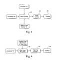
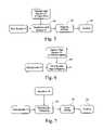
- FIGS. 3–7are schematic representations of possible methods of making wire elements having a fiber optic-based sensor of the present invention.
- FIG. 8is a plot of the wavelength change over time for a Bragg grating upon coating with adhesively bonded polyolefin tubing
- FIG. 9is a plot of the change in reflected peak position of an optical fiber Bragg grating in polyolefin tubing due to wear as a function of the thickness of the tube removed for two replicate tests;
- FIG. 10is a plot showing the response of Bragg sensors adhered and non-adhered to polyolefin tube subjected to two thermal cycles;
- FIG. 11is a plot showing the response of adhered (wear) and non-adhered (temperature) coated Bragg sensors within the same insulation subjected to wear damage;
- FIG. 12is a plot of the wavelength change as a function of position for a distributed sensor system adhered to a polyolefin insulator subjected to tensile loading;
- FIG. 13is a plot of the wavelength change as a function of position for a distributed sensor system adhered to a polyolefin insulator subjected to a wear damage event;
- FIG. 14is a plot of the wavelength change as a function of position for a distributed sensor system adhered to a polyolefin insulator subjected to a wear damage event and zeroed to monitor the occurrence of damage relative to a new baseline state;
- FIG. 15is a plot of the response of a Bragg sensor with a coating containing magnetostrictive particles in magnetic fields of varying strength.
- a “fiber optic condition sensor”means an optical fiber which is capable of being analyzed spectrally so as to detect at least one of strain displacement, temperature or other physical quantities at locations along the optical fiber's length of an element with which the sensor is associated.
- Exemplary fiber optic condition sensorsthat may be employed in the practice of this invention include grating-type (e.g., long period and/or Bragg gratings), interferometric-type and back-scattering type sensors as disclosed, for example, in U.S. Pat. No. 6,545,760 to Froggatt et al; U.S. Pat. No. 5,945,666 to Kersey; U.S. Pat. No. 5,430,817 to Vengsarkar; U.S. Pat. No.
- An “element” in need of condition detectioncan be virtually any structure with which the fiber optic condition sensor may be operatively associated and used so as to detect conditions thereof.
- Such elementsmay therefore be coated structures such as coated wires or wire bundles, as well as pipes, hoses, tubes or other conduits.
- FIG. 1Adepicts schematically a coated wire assembly CW in accordance with the present invention which comprises an integral fiber optic-based damage detector.
- the coated wire CWincludes at least one electrically conductive wire element 10 which is surrounded entirely by an electrically insulated sleeve 12 .
- the insulator sleeve 12covers the wire element 10 along its entire axial length (which is usually of an extreme or indefinite length).
- the coated wire CWintegrally includes a plurality of fiber optic sensors 14 in operative association with the insulator sleeve 12 . As shown in the embodiment of FIG. 1A , each of the fiber optic sensors is provided with a series of in-fiber Bragg gratings 16 spaced-apart along the optical fiber's axial length.
- the wire element 10may be formed from any conventional electrically conductive material. Most preferably, the wire element is in the form of a monofilamentary or multifilamentary wire, roving or braid formed of an electrically conductive metal or metal alloy.
- the wire element 10will typically be of extreme or indefinite length and the annular electrical insulator sleeve 12 will thus be continuously formed around the conductor along its entire length.
- the electrical insulator sleeve 12which coats the conductor 10 .
- the insulator sleeve 12will be formed of a pliable polymeric material, such as a polyolefin, polytetrafluoroethylene, fluorinated ethylene propylene, polyvinylidene fluoride, ethylene-tetrafluoroethylene, polyimide or the like.
- FIG. 1Bdepicts schematically a wire bundle WB comprised of a plurality of coated wires 11 and an integral fiber optic-based damage detector.
- the wire bundle WBis in and of itself conventional in that it includes an assembly of individual insulated electrical conductors 11 which are surrounded entirely by a protective insulating jacket or sheath 13 .
- the coated wires 11may be formed from any conventional electrically conductive material with insulation.
- the protective jacket 13covers the electrical conductors 11 along their entire axial length (which is usually of an extreme or indefinite length).
- the wire bundle WBintegrally includes a fiber optic damage detector comprised of a plurality of fiber optic sensors 14 in operative association with the protective jacket 13 .
- Each of the fiber optic sensors 14is provided with a series of in-fiber Bragg gratings 16 spaced-apart along the fiber's axial length.
- the protective insulation 13which contains the electrical wires 11 that comprise the wire bundle.
- the protective insulation 13will be formed of a pliable polymeric material; such as a polyolefin, polytetrafluoroethylene, fluorinated ethylene propylene, polyvinylidene fluoride, ethylene-tetrafluoroethylene, polyimide or the like.
- the protective insulationmay be a tape wrap, woven sleeve or extruded jacket.
- the WBintegrally includes a fiber optic damage detector comprised of a plurality of fiber optic sensors 14 in operative association with the protective jacket 13 .
- a fiber optic damage detectorcomprised of a plurality of fiber optic sensors 14 in operative association with the protective jacket 13 .
- each of the fiber optic sensors 14is provided with a series of in-fiber Bragg gratings 16 spaced-apart along the fiber's axial length.
- FIG. 1Cdepicts schematically another possible embodiment of a wire bundle WB′ of coated wires in accordance with the present invention which comprises an integral fiber optic-based damage detector.
- the wire bundle WB′ depicted in FIG. 1Cis structurally similar to the wire bundle WB depicted in FIG. 1B , with the principal exception being that the fiber optic sensors 14 with in-fiber Bragg gratings 16 are co-located physically at desired locations within protective jacket 13 surrounding the plural wires 11 forming wire bundle WB′, instead of being positioned physically within the sleeve 12 .
- the wires 11 and sensors 14are both surrounded physically and protected by the jacket 13 .
- each of the Bragg strain gratings 16is written on a discrete section of the optical fiber 14 and comprise a portion of the optical fiber where the index of refraction varies with a given periodicity.
- Optical radiationis transmitted over a plurality of contiguous predetermined wavelength ranges.
- the optical radiationreflects off the fiber optic Bragg gratings.
- the wavelength of the reflected optical radiationchanges.
- the strain on the individual gratings distributed over the length of optical fiberis determined by the difference between the current wavelength an earlier baseline wavelength measurement.
- the Bragg grating spacingmay change in response to other environmental factors, such as temperature.
- the optical fiber sensors 14are shown in the embodiment of FIGS. 1A and 1B as being embedded physically within the annular electrical insulator sleeve 12 or protective sheath 13 , respectively.
- the sensors 14may be incorporated into the insulator sleeve 12 or protective sheath 13 in any convenient manner and/or by any convenient means (e.g., via adhesive bonding). It will also be understood that the insulator sleeve 12 or protect sheath 13 containing the optical fiber sensor 14 may be any conventional covering including, but not limited to, extrusion coatings, tape wraps and/or woven covers.
- the sensors 14may be associated with the insulator 12 in virtually any geometry, such as a spiral winding around the conductor 10 and/or oriented substantially parallel to the insulator 12 (e.g., as depicted in FIGS. 1A and 1B ).
- the optical fiber sensors 14 shown in the embodiment of FIG. 1Care collocated physically within the WB contained in the protective sheath 13 . However, the sensors 14 may not be affixed to the electrical wires 11 or the protective sheath 13 . Similar to the embodiment of FIGS. 1A and 1B , the sensors 14 may be associated with the WB in virtually any geometry, such as a spiral winding around the bundle of electrical wires 11 and/or oriented substantially parallel to the electrical wires 11 as depicted in FIG. 1C .
- Important to the present inventionis the functionality of the fiber optic sensors 14 for detection of specific loading and damage modes on the coated wire element CW or wire bundle WB.
- Important to the present inventionare the residual stresses that are present between the fiber optic sensors 14 and the insulator sleeve 12 /protective jacket 13 .
- Also of importanceare the changes and occurrence of residual stresses between the fiber optic sensors 14 and the insulator sleeve 12 /jacket 13 . These residual stresses are developed by the adhesion of the sensors 14 to the insulator sleeve 12 /jacket 13 .
- Residual stresscan be produced by the relative coefficients of thermal expansion (CTE) of the insulator sleeve 12 /jacket 13 and the optical fiber sensor 14 or from dimensional changes in the insulator sleeve 12 /jacket 13 during curing. Mismatch of the CTE of the insulator sleeve 12 /jacket 13 adhered to the optical fiber sensor at an elevated temperature induces a residual stress which is exerted upon the sensor 14 when cooled.
- CTEthermal expansion
- a wavelength change in the Bragg grating 16 when adhered to or embedded within the insulator sleeve 12 /jacket 13which is greater than about 0.1 nm, and more preferably greater than at least about 1.0 nm up to about 4.0 nm (e.g., between about 2.2 nm to about 2.6 nm) relative to the wavelength of the initial zero state of the Bragg grating prior to being adhered to or embedded within the insulator.
- the adhesion of the optical fiber sensor 14 to the insulator sleeve 12 /jacket 13is also an important design criteria. Specifically, when the insulator sleeve 12 /jacket 13 is permanently damaged by plastic deformation or otherwise dimensionally changed due to any combination of mechanical, chemical or thermal loading the adhered optical fiber sensor 14 will have a new detectable strain state.
- the response of the optical fiber sensor 14 to temperaturemay be employed in accordance with the present invention so as to detect potential damage events.
- the temperature response of the optical fiber sensor 14is dependent on the CTE of the optical fiber and the CTE of any material adhered to the sensor 14 .
- the temperature responsewill be principally a function of the optical fiber sensor 14 alone for the embodiment shown in FIG. 1C , of the fiber sensor 14 and insulator coating 12 couple in the embodiment of FIGS. 1A and 1B .
- Applied mechanical loadsmay be detected by the coated wire CW and wire bundle WB embodiments depicted in FIGS. 1A–1C . These mechanical loads are primarily axially applied stresses, bending moments and/or localized pinch points.
- the optical fiber sensors 14are sensitive to external applied mechanical loads on the CW and WB.
- the fiber optic sensor arrangements of FIGS. 1A–1Cproduce responses that are proportional to the magnitudes of the applied loads.
- Permanent changes in statemay be detected by the coated wire CW and wire bundle WB embodiments depicted in FIGS. 1A–1C . These changes in state may be due to the presence of accumulated damage or loading of the coated CW and wire bundle WB.
- the sensor outputprovides the means to locate the region along the coated wire CW and wire bundle WB that has a new load state or damage.
- the new state or damagecan be measured relative to any previously recorded condition.
- the new state or damage conditioncan be used as a benchmark for characterizing any future changes in damage or condition of the coated wire CW and wire bundle WB.
- FIGS. 2A , and 2 Bschematically depict detection system response to damage and potentially damaging conditions of the present invention employing a fiber optic-based sensor 14 as described generally above with reference to FIGS. 1A and 1B .
- FIG. 2Ashows schematically a possible signal response associated with the CW being in an undamaged unloaded state
- FIG. 2Bshows schematically a possible signal response associated with the electrical insulator 12 being in a damaged or worn state.
- a region of insulation wear WRcauses a portion of the insulator 12 to be physically removed thereby changing the strain in the optical fiber sensor 14 .
- This strain change in the optical fiber sensor 14thus causes a shift in the reflected wavelength of one or more of the Bragg gratings 16 in the vicinity of the wear region WR.
- a change in the strain state relative to an initial zero stateis sensed by a system 20 described (e.g., as described more fully in U.S. Pat. No. 5,789,521) which is operatively connected to the fiber optic sensor 14 via standard optical cable 18 .
- the system 20may employ any conventional elements of data acquisition and signal processing well known to those familiar with the art and described in order to sense, store and output the changes in the strain state of the optical fiber sensor 14 .
- the response to detection of a change in the strain state in the data acquisition system 20may output an appropriate signal 22 to a monitor 24 which is capable of displaying visually and/or providing an aural warning of the detected change in state event.
- a monitor 24displays a visual indication that a wear region WR in the insulator 12 has occurred between Bragg gratings G 2 and G 4 .
- the datamay be stored electronically.
- FIG. 2Cshows schematically a possible signal response associated with the coated wire CW being subjected to a tension load L b .
- the tensile load L b on the coated wire CWproduces strain in the optical fiber sensors 14 .
- This strain change in the optical fiber sensor 14thus causes a shift in the reflected wavelength of the Bragg gratings 16 within the strained length of CW.
- the monitor 24displays a visual indication that a tensile stress in CW is present over Bragg gratings 16 G 1 to G 5 .
- FIG. 2Dshows schematically a possible signal response associated with the coated CW being loaded under bending moments L b .
- the bending load L b on the coated CWproduces both a tensile and compressive strain in the optical fiber sensors 14 .
- This strain change in the optical fiber sensors 14thus causes a shift in the reflected wavelength of the Bragg gratings 16 within the strained length of the coated wire CW.
- the monitor 24displays a visual indication that a bending stress in CW is present over Bragg gratings 16 G 2 to G 4 .
- FIG. 2Eshows schematically a possible signal response associated with the coated wire CW being subject to a pinching load L p .
- the pinch load L p on the coated wire CWproduces a localized axial tensile strain in the optical fiber sensors 14 .
- This strain change in the optical fiber sensors 14thus causes a shift in the reflected wavelength of the Bragg gratings 16 within the strained length of the coated wire CW.
- the monitor 24displays a visual indication that a pinching force in CW is present over Bragg gratings 16 G 3 .
- FIG. 3depicts one exemplary manner in which a fiber optic based damage detector may be made.
- electrical conductor 10may be advanced into a wire coating step 30 concurrently with the material to form the coating insulator 12 and the optical fiber sensor 14 .
- the insulator materialis extruded or otherwise applied continuously about the circumference of the conductor 10 along its entire axial length. While in such a softened state, one or more of the optical fiber sensors 14 may be embedded within the insulator 12 .
- the insulator 12may be cured (e.g., via convection, induction, or infrared heating techniques and/or via ultraviolet and electron beam radiation techniques), if needed, in step 32 , and then allowed to cool in step 34 if needed.
- curede.g., via convection, induction, or infrared heating techniques and/or via ultraviolet and electron beam radiation techniques
- FIG. 4depicts another preferred technique for making a fiber optic based damage detector.
- the optical fiber sensor 14may be incorporated into a tape of electrical insulator 14 which is wrapped around the conductor in step 40 .
- the thus insulator tape-wrapped conductoris then heated and/or cured (e.g., via convection, induction, or infrared heating techniques and/or via ultraviolet and electron beam radiation techniques) in step 42 followed by cooling in step 44 .
- the tape containing the optical fiber sensor 14forms a continuous insulating coating around the conductor 10 .
- FIG. 5depicts another exemplary manner in which a fiber optic based damage detector may be made.
- wire bundle 11may be advanced into a coating step 50 concurrently with the material to form the protective sleeve 13 and the optical fiber sensor 14 .
- the insulator materialis extruded or otherwise applied continuously about the circumference of the wire bundle 11 along its entire axial length. While in such a softened state, one or more of the optical fiber sensors 14 may be embedded within the protective sleeve 13 .
- the protective sleeve 13may be cured (e.g., via convection, induction, or infrared heating techniques and/or via ultraviolet and electron beam radiation techniques), if needed, in step 52 , and then allowed to cool in step 54 if needed.
- curede.g., via convection, induction, or infrared heating techniques and/or via ultraviolet and electron beam radiation techniques
- FIG. 6depicts another preferred technique for making a fiber optic based damage detector.
- the optical fiber sensor 14may be incorporated into a woven protective sleeve 13 which is used to cover the wire bundle in step 60 .
- the woven sleeve containing the optical fiber sensor 14forms a continuous protective sleeve around the wire bundle 13 .
- FIG. 7depicts another preferred technique for making a fiber optic based damage detector.
- the optical fiber sensor 14may be incorporated into a tape of protective sleeve 13 which is wrapped around the wire bundle in step 70 .
- the thus protective tape-wrapped bundleis then heated and/or cured (e.g., via convection, induction, or infrared heating techniques and/or via ultraviolet and electron beam radiation techniques) in step 72 followed by cooling in step 74 .
- the tape containing the optical fiber sensor 14forms a continuous protective sleeve around the wire bundle 13 .
- the tubingwas compressed to push entrapped air out of the tube and fully wet the fiber with the thermoplastic adhesive.
- the Bragg grating reflected peak positionwas continually monitored with the FiberPro system during the application and cooling of the polyolefin tubing.
- the change in the reflected wavelength peak position as a function of timeis given in FIG. 8 .
- the initial positive rise in the reflected wavelength responseis due to thermal sensitivity (response) of the sensor within the polyolefin tubing.
- the sensor responsechanges direction due to sensor cooling upon removing the heat source.
- the thermal plastic adhesivebonds the optical fiber sensor to the polyolefin at an elevated temperature.
- the high CTE of the polyolefin tube relative to that of the fused silica fiber optic sensorproduces higher contractions in the polyolefin than the fiber optic sensor. This mismatch of CTE and the restraining effect of the thermal plastic adhesive produce residual compressive stresses in the optical fiber.
- the difference between the initial and final reflected wavelengthsis due to the compressive strain associated with the contraction of the polyolefin material.
- Coatingswere prepared using a polymer matrix containing a range of particulate additives including TERFENOL-D powder from Etrema Products, Inc. and iron fines. The particulate were approximately 25% volume fraction of the coating system.
- the TERFENOL-D powder particle sizeswere less than 300 ⁇ m.
- the iron powderhad a particle size less than 40 mesh (425 ⁇ m).
- Optical fiber sensors including Bragg gratings(commercially available from Luna Innovations, Inc.) were coated with Spurr Low-Viscosity Embedding Media a four-part epoxy from Polysciences, Inc. This epoxy was used as the matrix material for these coatings. The approximately 2 mm thick coatings were cured at 70° C. for 16 hours. The total change in the reflected wavelengths of the coated optical fiber sensors were recorded for the four part epoxy with iron fines and TERFANOL-D particles. The reflected wavelength decreased by 1.5 to 3 nm for the coated optical fiber sensor relative to the uncoated condition. Application of the epoxy polymer produced compressive stresses in the optical fiber based sensor.
- Wear testswere performed by mounting the polyolefin tube and Bragg sensor assembly described in Example 1 in a metallographic epoxy mount which was cast in a cylindrical mold. A V-shaped groove was machined into the mount and the fiber Bragg grating in the polyolefin tube was placed into the groove. A five minute epoxy was used to fill in the groove around the damage sensor. Silicon carbide 180 grit abrasive paper was used to generate flat parallel surfaces on both ends of the metallographic mount. All grinding was performed using deionized water as a lubricant to minimize heating of the sample. The face of the mount containing the insulation damage sensor was ground down to expose the polyolefin tube. Digital calipers were used to measure the thickness of the mount.
- the mountwas placed in 500 ml of deionized water at room temperature. Once the mount equilibrated with the water temperature, the reflected Bragg peak position (wavelength) was recorded. The mount was then further ground and the thickness and peak position re-measured. This process was repeated until the fiber was exposed. The reflected peak position was plotted as a function of the change in thickness of the polyolefin insulation.
- the data traces for two replicate testsare provided in FIG. 9 .
- the wear processrelieved the compressive stress on the sensor resulting in a positive sensor response.
- the wear sensorwas developed to take advantage of the large change in peak position that is achieved when the fiber Bragg grating is adhered to a polymer coating at an elevated temperature. Strain in the fiber is developed during the incorporation of the fiber into the insulating material. The mismatch in coefficients of thermal expansion (CTE) between the optical fiber and the polymeric insulation produce stress in the fiber. It was observed that the wavelength change in the adhered Bragg grating is approximately ⁇ 2.2 to ⁇ 2.6 nm, relative to the initial non-adhered zero state.
- the positive change in reflected peak position as insulation (polyolefin tube) is removed by wear processesis due to the relaxation of compressive fiber strain as the cross sectional area of the insulation is decreased ( FIG. 9 ).
- the first Bragg sensorwas covered with a TEFLON® fluoropolymer sheath to minimize the adhesion and compressive residual stress of the optical fiber sensor.
- the purpose of this sensor covered with the TEFLON® fluoropolymer sheathwas to provide a temperature baseline.
- a second sensorwas coated directly with the polyolefin material to monitor damage using the methods described in Example 1. The response of each optical sensor during the coating process and second thermal cycle is shown in FIG. 10 .
- the adhered damage sensorresponded as shown previously in FIG. 8 , with a significant offset due to the resultant compressive residual stress.
- the non-adhered temperature sensorresponded primarily to the thermal effects. The sharp changes in the temperature sensor response were due to the release of built-up compressive strains.
- Example 4The polyolefin coated temperature and damage Bragg sensors of Example 4 were then tested for response to mechanical wear. As in Example 3, the polyolefin coated sensors were mounted to a polishing fixture and ground to simulate wear. The response from the sensors is shown in FIG. 11 . The response of the damage sensor under mechanical stress and the isolation of the temperature sensor is clearly demonstrated in the plots of FIG. 11 .
- An optical fiber sensor containing multiple Bragg gratingswas incorporated into an insulating polyolefin tube. Wire insulation was simulated by a 1 meter long semi-rigid adhesively lined polyolefin heat shrink tubing (3M Corporation). Initial wire insulation tests were conducted using the DSS 1550TM system (Luna Innovations) to monitor multiple distributed optical fiber Bragg gratings. The fiber was cleaned with isopropyl alcohol and then a thin coating of cyanoacrylate adhesive was applied to promote adhesion between the fiber and the polyolefin tubing. Approximately 1 meter of optical sensing fiber containing Bragg gratings spaced at 1 cm intervals was then placed into the adhesively lined polyolefin tubing. A heat gun was used to shrink the tubing and melt the thermoplastic adhesive lining. At the peak temperature, the tubing was compressed to push entrapped air out of the tube and fully wet the fiber with the thermoplastic adhesive.
- FIG. 12presents the output from the sensing fiber containing distributed Bragg gratings loaded in tension from approximately Bragg sensor number 35 to 50 . When the tensile load is removed the sensors return to the original zero condition.
- the simulated 1 meter long wirewas subject to a permanent damage event by cutting the polyolefin tubing with a scalpel.
- the damage statewas detected and the distributed sensor and sensor system output is provided in FIG. 13 .
- the damage condition given in FIG. 13is a permanent change is state. If it is desired the new state of the 1 meter long wire can be used as a new baseline provided in FIG. 14 . This effectively re-zero the system so that new conditions or damage states are measured relative to the new baseline.
- the optical fiber Bragg sensors of Example 2were exposed in a magnet coil to varying magnetic field intensities of up to 55 kAT/m.
- FIG. 15gives the output of the fiber optic Bragg sensor for a range of magnetic field intensities. The four tests were performed for these sensors coated with TERFENOL-D and epoxy coatings.
Landscapes
- Physics & Mathematics (AREA)
- General Physics & Mathematics (AREA)
- Chemical & Material Sciences (AREA)
- Analytical Chemistry (AREA)
- Length Measuring Devices By Optical Means (AREA)
Abstract
Description
Claims (25)
Priority Applications (1)
| Application Number | Priority Date | Filing Date | Title |
|---|---|---|---|
| US10/720,694US7154081B1 (en) | 2002-11-26 | 2003-11-25 | Composite structures, such as coated wiring assemblies, having integral fiber optic-based condition detectors and systems which employ the same |
Applications Claiming Priority (2)
| Application Number | Priority Date | Filing Date | Title |
|---|---|---|---|
| US42890802P | 2002-11-26 | 2002-11-26 | |
| US10/720,694US7154081B1 (en) | 2002-11-26 | 2003-11-25 | Composite structures, such as coated wiring assemblies, having integral fiber optic-based condition detectors and systems which employ the same |
Publications (1)
| Publication Number | Publication Date |
|---|---|
| US7154081B1true US7154081B1 (en) | 2006-12-26 |
Family
ID=37569448
Family Applications (1)
| Application Number | Title | Priority Date | Filing Date |
|---|---|---|---|
| US10/720,694Expired - Fee RelatedUS7154081B1 (en) | 2002-11-26 | 2003-11-25 | Composite structures, such as coated wiring assemblies, having integral fiber optic-based condition detectors and systems which employ the same |
Country Status (1)
| Country | Link |
|---|---|
| US (1) | US7154081B1 (en) |
Cited By (61)
| Publication number | Priority date | Publication date | Assignee | Title |
|---|---|---|---|---|
| US20070265503A1 (en)* | 2006-03-22 | 2007-11-15 | Hansen Medical, Inc. | Fiber optic instrument sensing system |
| US20080204706A1 (en)* | 2004-03-11 | 2008-08-28 | Sylvain Magne | System For Distributed Measurement of the Curves of a Structure |
| US20080218770A1 (en)* | 2007-02-02 | 2008-09-11 | Hansen Medical, Inc. | Robotic surgical instrument and methods using bragg fiber sensors |
| US20080227349A1 (en)* | 2007-03-14 | 2008-09-18 | Eyck Lawrence G Ten | Temperature sensing fabric |
| US20080272311A1 (en)* | 2005-04-28 | 2008-11-06 | Claudio Oliveira Egalon | Improved Reversible, low cost, distributed optical fiber sensor with high spatial resolution |
| FR2916838A1 (en)* | 2007-05-29 | 2008-12-05 | Schneider Electric Ind Sas | Integrated deformation monitoring device for e.g. wall of electrical case, has optical fiber with protection sheath made of polyimide material, and cover including thermosetting matrix composite materials constituting insulating piece |
| US20090137952A1 (en)* | 2007-08-14 | 2009-05-28 | Ramamurthy Bhaskar S | Robotic instrument systems and methods utilizing optical fiber sensor |
| US20090185772A1 (en)* | 2008-01-22 | 2009-07-23 | General Electric Company | Fiberoptic patient health multi-parameter monitoring devices and system |
| US20090260834A1 (en)* | 2004-07-07 | 2009-10-22 | Sensornet Limited | Intervention Rod |
| DE102008026731A1 (en)* | 2008-06-02 | 2009-12-10 | Technische Universität Chemnitz | Method for determining wear state of oblong tension or power transmission unit, involves detecting change of length or expansion of wave guide, where wave guide is integrated at or in tension or power transmission unit |
| US20100202726A1 (en)* | 2009-01-30 | 2010-08-12 | Claudio Oliveira Egalon | Side illuminated multi point multi parameter optical fiber sensor |
| US20110051123A1 (en)* | 2009-09-03 | 2011-03-03 | Honda Motor Co., Ltd. | Optical fiber sensor, pressure sensor, end effector and sensor signal processor |
| US20110231110A1 (en)* | 2010-03-16 | 2011-09-22 | Johnston Robert T | Fiber Optic Sensor System for Detecting Surface Wear |
| US8050523B2 (en) | 2007-04-20 | 2011-11-01 | Koninklijke Philips Electronics N.V. | Optical fiber shape sensing systems |
| US8098967B1 (en)* | 2010-10-08 | 2012-01-17 | Michael Louis Bazzone | Generator protection system |
| US20120039358A1 (en)* | 2009-02-24 | 2012-02-16 | Thomas Bosselmann | Device for Measuring Temperature in Electromagnetic Fields |
| US8139905B1 (en)* | 2010-10-08 | 2012-03-20 | Michael Louis Bazzone | Generator protection system |
| US20120086443A1 (en)* | 2010-10-08 | 2012-04-12 | Bazzone Michael L | Generator Operation Monitoring |
| US20120099097A1 (en)* | 2009-03-18 | 2012-04-26 | Peter Coupe | System and method for uniform and localized wall thickness measurement using fiber optic sensors |
| US20120201656A1 (en)* | 2011-02-09 | 2012-08-09 | Johnston Robert T | Multiplexed optical fiber wear sensor |
| US20120277531A1 (en)* | 2011-04-28 | 2012-11-01 | Beat Krattiger | Bend sensor |
| WO2013083192A1 (en)* | 2011-12-07 | 2013-06-13 | Aktiebolaget Skf | Optical angle encoder |
| US20130154632A1 (en)* | 2010-09-01 | 2013-06-20 | Optasense Holdings Limited | Magnetic Field Detector |
| US20140112614A1 (en)* | 2012-10-23 | 2014-04-24 | Nexans | Electrical line for a motor vehicle |
| US20140159715A1 (en)* | 2011-07-15 | 2014-06-12 | Optasense Holdings Limited | Portal Monitoring |
| US8780339B2 (en) | 2009-07-15 | 2014-07-15 | Koninklijke Philips N.V. | Fiber shape sensing systems and methods |
| US20140305744A1 (en)* | 2012-01-24 | 2014-10-16 | Kone Corporation | Rope of a lifting device, a rope arrangement, an elevator and a condition monitoring method for the rope of a lifting device |
| US20140331779A1 (en)* | 2013-05-10 | 2014-11-13 | Corning Cable Systems Llc | Structural strain sensing optical cable |
| US20140345978A1 (en)* | 2012-03-22 | 2014-11-27 | Kone Corporation | Travelling cable of an elevator, and an elevator |
| US8989528B2 (en) | 2006-02-22 | 2015-03-24 | Hansen Medical, Inc. | Optical fiber grating sensors and methods of manufacture |
| WO2016022094A1 (en)* | 2014-08-04 | 2016-02-11 | Halliburton Energy Services, Inc. | Enhanced slickline |
| JP2016057231A (en)* | 2014-09-11 | 2016-04-21 | 鹿島建設株式会社 | Measuring device, strain measuring method, PC steel strand, and optical fiber member |
| US9358076B2 (en) | 2011-01-20 | 2016-06-07 | Hansen Medical, Inc. | System and method for endoluminal and translumenal therapy |
| DE102015006697A1 (en) | 2015-05-21 | 2016-11-24 | Universität Stuttgart | Optical method and arrangement for measuring residual stress, in particular on coated objects |
| GB2539894A (en)* | 2015-06-29 | 2017-01-04 | Optasense Holdings Ltd | Monitoring of power cables |
| WO2017039658A1 (en)* | 2015-09-02 | 2017-03-09 | Halliburton Energy Services, Inc | Multi-parameter optical fiber sensing for reservoir compaction engineering |
| US9632275B2 (en) | 2012-06-15 | 2017-04-25 | Commscope Technologies Llc | Secure jacket |
| WO2017087133A1 (en)* | 2015-11-18 | 2017-05-26 | Corning Optical Communications LLC | System and method for monitoring strain in roadway optical cable |
| US20170254191A1 (en)* | 2014-10-17 | 2017-09-07 | Halliburton Energy Services, Inc. | Well Monitoring with Optical Electromagnetic Sensing System |
| WO2017165381A1 (en)* | 2016-03-21 | 2017-09-28 | Kansas State University Research Foundation | Fluid-filled hollow optical fiber cell |
| WO2018134188A1 (en)* | 2017-01-19 | 2018-07-26 | Fraunhofer-Gesellschaft zur Förderung der angewandten Forschung e.V. | Optical insulation-monitoring device and methods for using and producing same |
| US20180231595A1 (en)* | 2017-02-10 | 2018-08-16 | Airbus Operations Gmbh | Protection and fault detection for high voltage power lines on aircraft |
| US10066968B2 (en) | 2016-06-01 | 2018-09-04 | King Fahd University Of Petroleum And Minerals | Structural element with branched optical fibers for parameter measurement |
| US10130427B2 (en) | 2010-09-17 | 2018-11-20 | Auris Health, Inc. | Systems and methods for positioning an elongate member inside a body |
| US20190072437A1 (en)* | 2017-09-06 | 2019-03-07 | Carnegie Mellon University | Distributed Sensing of Electromagnetic Components Using Optical Fiber Based Methods |
| JP2019070594A (en)* | 2017-10-10 | 2019-05-09 | 住友電工スチールワイヤー株式会社 | Damage detection method of pc cable |
| US10304577B2 (en)* | 2015-08-12 | 2019-05-28 | Westinghouse Electric Company Llc | Method for measuring bow/twist of a fuel assembly |
| DE102018125416A1 (en)* | 2018-10-15 | 2020-04-16 | Auto-Kabel Management Gmbh | Motor vehicle electrical system and method for operating a motor vehicle electrical system |
| US10667720B2 (en) | 2011-07-29 | 2020-06-02 | Auris Health, Inc. | Apparatus and methods for fiber integration and registration |
| US10741304B1 (en)* | 2019-04-11 | 2020-08-11 | Nexans | Cable with fiber optic sensor elements |
| CN111733620A (en)* | 2020-07-10 | 2020-10-02 | 广东坚宜佳五金制品有限公司 | lasso |
| JP2020537748A (en)* | 2017-10-17 | 2020-12-24 | レモーザ・ソチエタ・ア・レスポンサビリタ・リミタータRemosa S.R.L. | Erosion monitoring system for components of flow catalytic decomposition |
| US10957176B2 (en) | 2016-11-11 | 2021-03-23 | Carrier Corporation | High sensitivity fiber optic based detection |
| US11151853B2 (en) | 2016-11-11 | 2021-10-19 | Carrier Corporation | High sensitivity fiber optic based detection |
| US11327261B1 (en) | 2020-04-22 | 2022-05-10 | Space Systems/Loral, Llc | Structural arrangements using carbon fiber braid |
| ES2919086A1 (en)* | 2022-06-28 | 2022-07-21 | Fibsen Monitorizaciones S L | MODULABLE MULTIPARAMETRIC PROBE OF FIBER OPTIC SENSORS |
| US20220259777A1 (en)* | 2019-06-19 | 2022-08-18 | Staubli Faverges | Textile machine, weaving loom comprising such a textile machine and associated methods |
| US20230039794A1 (en)* | 2009-09-15 | 2023-02-09 | Astro Technology Group, Llc | Apparatus, fiber optic sensor assembly and sensor housing assembly utilizing viscous material composition to mitigate signal attenuation |
| US20230408350A1 (en)* | 2022-05-31 | 2023-12-21 | Simmonds Precision Products, Inc. | Bracelet sensing array |
| US11899080B2 (en) | 2017-09-06 | 2024-02-13 | United States Department Of Energy | Optical sensing of magnetic fields using magnetically sensitive materials |
| US12025568B1 (en)* | 2022-12-08 | 2024-07-02 | Indeximate Ltd. | Power cable health monitoring method |
Citations (14)
| Publication number | Priority date | Publication date | Assignee | Title |
|---|---|---|---|---|
| US4634977A (en)* | 1982-12-27 | 1987-01-06 | Honeywell Inc. | High accuracy mapping of magnetic fields with a fiber optic interferometer |
| US5015859A (en)* | 1989-09-25 | 1991-05-14 | General Electric Company | Method and apparatus for detecting wear |
| US5430817A (en) | 1994-03-31 | 1995-07-04 | At&T Corp. | Optical systems and devices using long period spectral shaping devices |
| US5792284A (en) | 1991-05-22 | 1998-08-11 | Fox Technology Kb | Magnetostrictive powder composite and methods for the manufacture thereof |
| US5798521A (en) | 1996-02-27 | 1998-08-25 | The United States Of America As Represented By The Administrator Of The National Aeronautics And Space Administration | Apparatus and method for measuring strain in bragg gratings |
| US5945666A (en) | 1996-05-20 | 1999-08-31 | The United States Of America As Represented By The Secretary Of The Navy | Hybrid fiber bragg grating/long period fiber grating sensor for strain/temperature discrimination |
| US6056436A (en) | 1997-02-20 | 2000-05-02 | University Of Maryland | Simultaneous measurement of temperature and strain using optical sensors |
| US6265880B1 (en) | 1999-06-15 | 2001-07-24 | The United States Of America As Represented By The Secretary Of The Air Force | Apparatus and method for detecting conduit chafing |
| US6545760B1 (en) | 1999-03-25 | 2003-04-08 | The United States Of America As Represented By The Administrator Of The National Aeronautics And Space Administration | Apparatus and method for measuring strain in optical fibers using rayleigh scatter |
| US6559437B1 (en)* | 2000-09-20 | 2003-05-06 | Ralph E. Pope, Jr. | Fiber optic damage sensor for wire and cable |
| US20030127587A1 (en) | 2001-12-21 | 2003-07-10 | Eric Udd | Fiber grating environmental sensing system |
| US20030174924A1 (en) | 2002-03-14 | 2003-09-18 | Tennyson Roderick C. | Monitoring of large structures using brillouin spectrum analysis |
| US6784983B1 (en)* | 1999-05-06 | 2004-08-31 | Leiv Eiriksson Nyfotek As | System for monitoring cables |
| US6888124B1 (en)* | 1999-03-24 | 2005-05-03 | Shell Oil Company | Method to monitor internal parameters of electrical motor systems |
- 2003
- 2003-11-25USUS10/720,694patent/US7154081B1/ennot_activeExpired - Fee Related
Patent Citations (14)
| Publication number | Priority date | Publication date | Assignee | Title |
|---|---|---|---|---|
| US4634977A (en)* | 1982-12-27 | 1987-01-06 | Honeywell Inc. | High accuracy mapping of magnetic fields with a fiber optic interferometer |
| US5015859A (en)* | 1989-09-25 | 1991-05-14 | General Electric Company | Method and apparatus for detecting wear |
| US5792284A (en) | 1991-05-22 | 1998-08-11 | Fox Technology Kb | Magnetostrictive powder composite and methods for the manufacture thereof |
| US5430817A (en) | 1994-03-31 | 1995-07-04 | At&T Corp. | Optical systems and devices using long period spectral shaping devices |
| US5798521A (en) | 1996-02-27 | 1998-08-25 | The United States Of America As Represented By The Administrator Of The National Aeronautics And Space Administration | Apparatus and method for measuring strain in bragg gratings |
| US5945666A (en) | 1996-05-20 | 1999-08-31 | The United States Of America As Represented By The Secretary Of The Navy | Hybrid fiber bragg grating/long period fiber grating sensor for strain/temperature discrimination |
| US6056436A (en) | 1997-02-20 | 2000-05-02 | University Of Maryland | Simultaneous measurement of temperature and strain using optical sensors |
| US6888124B1 (en)* | 1999-03-24 | 2005-05-03 | Shell Oil Company | Method to monitor internal parameters of electrical motor systems |
| US6545760B1 (en) | 1999-03-25 | 2003-04-08 | The United States Of America As Represented By The Administrator Of The National Aeronautics And Space Administration | Apparatus and method for measuring strain in optical fibers using rayleigh scatter |
| US6784983B1 (en)* | 1999-05-06 | 2004-08-31 | Leiv Eiriksson Nyfotek As | System for monitoring cables |
| US6265880B1 (en) | 1999-06-15 | 2001-07-24 | The United States Of America As Represented By The Secretary Of The Air Force | Apparatus and method for detecting conduit chafing |
| US6559437B1 (en)* | 2000-09-20 | 2003-05-06 | Ralph E. Pope, Jr. | Fiber optic damage sensor for wire and cable |
| US20030127587A1 (en) | 2001-12-21 | 2003-07-10 | Eric Udd | Fiber grating environmental sensing system |
| US20030174924A1 (en) | 2002-03-14 | 2003-09-18 | Tennyson Roderick C. | Monitoring of large structures using brillouin spectrum analysis |
Cited By (129)
| Publication number | Priority date | Publication date | Assignee | Title |
|---|---|---|---|---|
| US20080204706A1 (en)* | 2004-03-11 | 2008-08-28 | Sylvain Magne | System For Distributed Measurement of the Curves of a Structure |
| US20090260834A1 (en)* | 2004-07-07 | 2009-10-22 | Sensornet Limited | Intervention Rod |
| US7769260B2 (en)* | 2004-07-07 | 2010-08-03 | Sensornet Limited | Intervention rod |
| USRE43937E1 (en) | 2005-04-28 | 2013-01-22 | Claudio Oliveira Egalon | Reversible, low cost, distributed optical fiber sensor with high spatial resolution |
| US20080272311A1 (en)* | 2005-04-28 | 2008-11-06 | Claudio Oliveira Egalon | Improved Reversible, low cost, distributed optical fiber sensor with high spatial resolution |
| US7473906B2 (en) | 2005-04-28 | 2009-01-06 | Claudio Oliveira Egalon | Reversible, low cost, distributed optical fiber sensor with high spatial resolution |
| US8989528B2 (en) | 2006-02-22 | 2015-03-24 | Hansen Medical, Inc. | Optical fiber grating sensors and methods of manufacture |
| US20070265503A1 (en)* | 2006-03-22 | 2007-11-15 | Hansen Medical, Inc. | Fiber optic instrument sensing system |
| US20080218770A1 (en)* | 2007-02-02 | 2008-09-11 | Hansen Medical, Inc. | Robotic surgical instrument and methods using bragg fiber sensors |
| US7787726B2 (en)* | 2007-03-14 | 2010-08-31 | General Electric Company | Temperature sensing fabric |
| US20080227349A1 (en)* | 2007-03-14 | 2008-09-18 | Eyck Lawrence G Ten | Temperature sensing fabric |
| US8818143B2 (en) | 2007-04-20 | 2014-08-26 | Koninklijke Philips Electronics N.V. | Optical fiber instrument system for detecting twist of elongated instruments |
| US8811777B2 (en) | 2007-04-20 | 2014-08-19 | Koninklijke Philips Electronics N.V. | Optical fiber shape sensing systems |
| US8705903B2 (en) | 2007-04-20 | 2014-04-22 | Koninklijke Philips N.V. | Optical fiber instrument system for detecting and decoupling twist effects |
| US8515215B2 (en) | 2007-04-20 | 2013-08-20 | Koninklijke Philips Electronics N.V. | Optical fiber shape sensing systems |
| US8050523B2 (en) | 2007-04-20 | 2011-11-01 | Koninklijke Philips Electronics N.V. | Optical fiber shape sensing systems |
| US20100132477A1 (en)* | 2007-05-29 | 2010-06-03 | Schneider Electric Industries Sas | Integrated device for monitoring deformations of an electrically insulating part and method for manufacturing one such device |
| WO2009004137A3 (en)* | 2007-05-29 | 2009-04-16 | Schneider Electric Ind Sas | Integrated device for monitoring the deformations of an electrically insulating part and method of manufacturing such a device |
| US8215179B2 (en) | 2007-05-29 | 2012-07-10 | Schneider Electric Industries Sas | Integrated device for monitoring deformations of an electrically insulating part and method for manufacturing one such device |
| FR2916838A1 (en)* | 2007-05-29 | 2008-12-05 | Schneider Electric Ind Sas | Integrated deformation monitoring device for e.g. wall of electrical case, has optical fiber with protection sheath made of polyimide material, and cover including thermosetting matrix composite materials constituting insulating piece |
| AU2008270172B2 (en)* | 2007-05-29 | 2013-01-31 | Schneider Electric Industries Sas | Integrated device for monitoring the deformations of an electrically insulating part and method of manufacturing such a device |
| US10907956B2 (en) | 2007-08-14 | 2021-02-02 | Koninklijke Philips Electronics Nv | Instrument systems and methods utilizing optical fiber sensor |
| US9404734B2 (en) | 2007-08-14 | 2016-08-02 | Koninklijke Philips Electronics N.V. | System and method for sensing shape of elongated instrument |
| US20090137952A1 (en)* | 2007-08-14 | 2009-05-28 | Ramamurthy Bhaskar S | Robotic instrument systems and methods utilizing optical fiber sensor |
| US9186046B2 (en) | 2007-08-14 | 2015-11-17 | Koninklijke Philips Electronics N.V. | Robotic instrument systems and methods utilizing optical fiber sensor |
| US9186047B2 (en) | 2007-08-14 | 2015-11-17 | Koninklijke Philips Electronics N.V. | Instrument systems and methods utilizing optical fiber sensor |
| US8864655B2 (en) | 2007-08-14 | 2014-10-21 | Koninklijke Philips Electronics N.V. | Fiber optic instrument shape sensing system and method |
| US9441954B2 (en) | 2007-08-14 | 2016-09-13 | Koninklijke Philips Electronics N.V. | System and method for calibration of optical fiber instrument |
| US9726476B2 (en) | 2007-08-14 | 2017-08-08 | Koninklijke Philips Electronics N.V. | Fiber optic instrument orientation sensing system and method |
| US11067386B2 (en) | 2007-08-14 | 2021-07-20 | Koninklijke Philips N.V. | Instrument systems and methods utilizing optical fiber sensor |
| US9500473B2 (en) | 2007-08-14 | 2016-11-22 | Koninklijke Philips Electronics N.V. | Optical fiber instrument system and method with motion-based adjustment |
| US9500472B2 (en) | 2007-08-14 | 2016-11-22 | Koninklijke Philips Electronics N.V. | System and method for sensing shape of elongated instrument |
| US8009946B2 (en)* | 2008-01-22 | 2011-08-30 | General Electric Company | Fiberoptic patient health multi-parameter monitoring devices and system |
| US20090185772A1 (en)* | 2008-01-22 | 2009-07-23 | General Electric Company | Fiberoptic patient health multi-parameter monitoring devices and system |
| DE102008026731A1 (en)* | 2008-06-02 | 2009-12-10 | Technische Universität Chemnitz | Method for determining wear state of oblong tension or power transmission unit, involves detecting change of length or expansion of wave guide, where wave guide is integrated at or in tension or power transmission unit |
| US8463083B2 (en) | 2009-01-30 | 2013-06-11 | Claudio Oliveira Egalon | Side illuminated multi point multi parameter optical fiber sensor |
| US8909004B2 (en) | 2009-01-30 | 2014-12-09 | Claudio Oliveira Egalon | Side illuminated multi point multi parameter |
| US20150055133A1 (en)* | 2009-01-30 | 2015-02-26 | Claudio Oliveira Egalon | Side illuminated multi point multi parameter optical fiber sensor |
| US20100202726A1 (en)* | 2009-01-30 | 2010-08-12 | Claudio Oliveira Egalon | Side illuminated multi point multi parameter optical fiber sensor |
| US10088410B2 (en)* | 2009-01-30 | 2018-10-02 | Claudio Oliveira Egalon | Side illuminated multi point multi parameter optical fiber sensor |
| US10876960B2 (en) | 2009-01-30 | 2020-12-29 | Claudio Egalon | Side illuminated multi point multi parameter optical fiber sensor |
| US20120039358A1 (en)* | 2009-02-24 | 2012-02-16 | Thomas Bosselmann | Device for Measuring Temperature in Electromagnetic Fields |
| US20120099097A1 (en)* | 2009-03-18 | 2012-04-26 | Peter Coupe | System and method for uniform and localized wall thickness measurement using fiber optic sensors |
| US8941821B2 (en)* | 2009-03-18 | 2015-01-27 | Schlumberger Technology Corporation | System and method for uniform and localized wall thickness measurement using fiber optic sensors |
| US8780339B2 (en) | 2009-07-15 | 2014-07-15 | Koninklijke Philips N.V. | Fiber shape sensing systems and methods |
| US8547534B2 (en)* | 2009-09-03 | 2013-10-01 | Honda Motor Co., Ltd. | Optical fiber sensor, pressure sensor, end effector and sensor signal processor |
| US20110051123A1 (en)* | 2009-09-03 | 2011-03-03 | Honda Motor Co., Ltd. | Optical fiber sensor, pressure sensor, end effector and sensor signal processor |
| US20230039794A1 (en)* | 2009-09-15 | 2023-02-09 | Astro Technology Group, Llc | Apparatus, fiber optic sensor assembly and sensor housing assembly utilizing viscous material composition to mitigate signal attenuation |
| US8571813B2 (en)* | 2010-03-16 | 2013-10-29 | Siemens Energy, Inc. | Fiber optic sensor system for detecting surface wear |
| US20110231110A1 (en)* | 2010-03-16 | 2011-09-22 | Johnston Robert T | Fiber Optic Sensor System for Detecting Surface Wear |
| US20130154632A1 (en)* | 2010-09-01 | 2013-06-20 | Optasense Holdings Limited | Magnetic Field Detector |
| US9459329B2 (en)* | 2010-09-01 | 2016-10-04 | Optasense Holdings Limited | Magnetic field detector |
| US10130427B2 (en) | 2010-09-17 | 2018-11-20 | Auris Health, Inc. | Systems and methods for positioning an elongate member inside a body |
| US12310669B2 (en) | 2010-09-17 | 2025-05-27 | Auris Health, Inc. | Systems and methods for positioning an elongate member inside a body |
| US11213356B2 (en) | 2010-09-17 | 2022-01-04 | Auris Health, Inc. | Systems and methods for positioning an elongate member inside a body |
| US10555780B2 (en) | 2010-09-17 | 2020-02-11 | Auris Health, Inc. | Systems and methods for positioning an elongate member inside a body |
| US8098967B1 (en)* | 2010-10-08 | 2012-01-17 | Michael Louis Bazzone | Generator protection system |
| US8139905B1 (en)* | 2010-10-08 | 2012-03-20 | Michael Louis Bazzone | Generator protection system |
| US20120086443A1 (en)* | 2010-10-08 | 2012-04-12 | Bazzone Michael L | Generator Operation Monitoring |
| US9358076B2 (en) | 2011-01-20 | 2016-06-07 | Hansen Medical, Inc. | System and method for endoluminal and translumenal therapy |
| US10350390B2 (en) | 2011-01-20 | 2019-07-16 | Auris Health, Inc. | System and method for endoluminal and translumenal therapy |
| CN103460008A (en)* | 2011-02-09 | 2013-12-18 | 西门子能量股份有限公司 | Multiplexed optical fiber wear sensor |
| US8790074B2 (en)* | 2011-02-09 | 2014-07-29 | Siemens Energy, Inc. | Multiplexed optical fiber wear sensor |
| US20120201656A1 (en)* | 2011-02-09 | 2012-08-09 | Johnston Robert T | Multiplexed optical fiber wear sensor |
| WO2012109183A1 (en)* | 2011-02-09 | 2012-08-16 | Siemens Energy, Inc. | Multiplexed optical fiber wear sensor |
| US20120277531A1 (en)* | 2011-04-28 | 2012-11-01 | Beat Krattiger | Bend sensor |
| US9423523B2 (en)* | 2011-07-15 | 2016-08-23 | Optasense Holdings Limited | Portal monitoring |
| US20140159715A1 (en)* | 2011-07-15 | 2014-06-12 | Optasense Holdings Limited | Portal Monitoring |
| US10667720B2 (en) | 2011-07-29 | 2020-06-02 | Auris Health, Inc. | Apparatus and methods for fiber integration and registration |
| US11419518B2 (en) | 2011-07-29 | 2022-08-23 | Auris Health, Inc. | Apparatus and methods for fiber integration and registration |
| WO2013083192A1 (en)* | 2011-12-07 | 2013-06-13 | Aktiebolaget Skf | Optical angle encoder |
| US20140305744A1 (en)* | 2012-01-24 | 2014-10-16 | Kone Corporation | Rope of a lifting device, a rope arrangement, an elevator and a condition monitoring method for the rope of a lifting device |
| US9834409B2 (en)* | 2012-01-24 | 2017-12-05 | Kone Corporation | Rope of a lifting device for an elevator and a condition monitoring method for the rope |
| US9944494B2 (en)* | 2012-03-22 | 2018-04-17 | Kone Corporation | Travelling cable of an elevator, and an elevator |
| US20140345978A1 (en)* | 2012-03-22 | 2014-11-27 | Kone Corporation | Travelling cable of an elevator, and an elevator |
| US9632275B2 (en) | 2012-06-15 | 2017-04-25 | Commscope Technologies Llc | Secure jacket |
| US9437350B2 (en)* | 2012-10-23 | 2016-09-06 | Nexans | Electrical line for a motor vehicle |
| US20140112614A1 (en)* | 2012-10-23 | 2014-04-24 | Nexans | Electrical line for a motor vehicle |
| EP2725398A1 (en)* | 2012-10-23 | 2014-04-30 | Nexans | Electric cable for a motor vehicle |
| US9557232B2 (en)* | 2013-05-10 | 2017-01-31 | Corning Optical Communications LLC | Structural strain sensing optical cable |
| US20140331779A1 (en)* | 2013-05-10 | 2014-11-13 | Corning Cable Systems Llc | Structural strain sensing optical cable |
| GB2542960A (en)* | 2014-08-04 | 2017-04-05 | Halliburton Energy Services Inc | Enhanced slickline |
| US10370909B2 (en) | 2014-08-04 | 2019-08-06 | Halliburton Energy Services, Inc. | Enhanced slickline |
| WO2016022094A1 (en)* | 2014-08-04 | 2016-02-11 | Halliburton Energy Services, Inc. | Enhanced slickline |
| JP2016057231A (en)* | 2014-09-11 | 2016-04-21 | 鹿島建設株式会社 | Measuring device, strain measuring method, PC steel strand, and optical fiber member |
| US10704377B2 (en)* | 2014-10-17 | 2020-07-07 | Halliburton Energy Services, Inc. | Well monitoring with optical electromagnetic sensing system |
| US20170254191A1 (en)* | 2014-10-17 | 2017-09-07 | Halliburton Energy Services, Inc. | Well Monitoring with Optical Electromagnetic Sensing System |
| DE102015006697A1 (en) | 2015-05-21 | 2016-11-24 | Universität Stuttgart | Optical method and arrangement for measuring residual stress, in particular on coated objects |
| DE102015006697B4 (en) | 2015-05-21 | 2018-08-02 | Universität Stuttgart | Optical method and arrangement for measuring residual stress, in particular on coated objects |
| US10481020B2 (en) | 2015-05-21 | 2019-11-19 | Universität Stuttgart | Optical method and arrangement for measuring residual stresses, in particular in coated objects |
| WO2016184578A1 (en) | 2015-05-21 | 2016-11-24 | Universität Stuttgart | Optical method and arrangement for measuring residual stresses, in particular in coated objects |
| WO2017001826A1 (en)* | 2015-06-29 | 2017-01-05 | Optasense Holdings Limited | Monitoring of power cables with distributed fibre optic sensing |
| US10775425B2 (en) | 2015-06-29 | 2020-09-15 | Optasense Holdings Limited | Monitoring of power cables with distributed fibre optic sensing |
| GB2539894A (en)* | 2015-06-29 | 2017-01-04 | Optasense Holdings Ltd | Monitoring of power cables |
| GB2539894B (en)* | 2015-06-29 | 2019-03-27 | Optasense Holdings Ltd | Monitoring of power cables |
| US10304577B2 (en)* | 2015-08-12 | 2019-05-28 | Westinghouse Electric Company Llc | Method for measuring bow/twist of a fuel assembly |
| WO2017039658A1 (en)* | 2015-09-02 | 2017-03-09 | Halliburton Energy Services, Inc | Multi-parameter optical fiber sensing for reservoir compaction engineering |
| US10794175B2 (en) | 2015-09-02 | 2020-10-06 | Halliburton Energy Services, Inc. | Multi-parameter optical fiber sensing for reservoir compaction engineering |
| US10533907B2 (en) | 2015-11-18 | 2020-01-14 | Corning Optical Communications LLC | System and method for monitoring strain in roadway optical cable |
| WO2017087133A1 (en)* | 2015-11-18 | 2017-05-26 | Corning Optical Communications LLC | System and method for monitoring strain in roadway optical cable |
| US10534134B2 (en) | 2016-03-21 | 2020-01-14 | Kansas State University Research Foundation | Fluid-filled hollow optical fiber cell |
| WO2017165381A1 (en)* | 2016-03-21 | 2017-09-28 | Kansas State University Research Foundation | Fluid-filled hollow optical fiber cell |
| US10168188B2 (en) | 2016-06-01 | 2019-01-01 | King Fahd University Of Petroleum And Minerals | Silica fiber measurement system comprising a branched optical fiber embedded in a structural element |
| US10161767B2 (en) | 2016-06-01 | 2018-12-25 | King Fahd University Of Petroleum And Minerals | Diagnostic and measurement system comprising a branched optical fiber embedded in a structural element |
| US10066968B2 (en) | 2016-06-01 | 2018-09-04 | King Fahd University Of Petroleum And Minerals | Structural element with branched optical fibers for parameter measurement |
| US10957176B2 (en) | 2016-11-11 | 2021-03-23 | Carrier Corporation | High sensitivity fiber optic based detection |
| US11151853B2 (en) | 2016-11-11 | 2021-10-19 | Carrier Corporation | High sensitivity fiber optic based detection |
| US11474142B2 (en) | 2017-01-19 | 2022-10-18 | Fraunhofer-Gesellschaft Zur Forderung Der Angewandten Forschung E.V. | Optical insulation-monitoring device and method for using and producing same |
| WO2018134188A1 (en)* | 2017-01-19 | 2018-07-26 | Fraunhofer-Gesellschaft zur Förderung der angewandten Forschung e.V. | Optical insulation-monitoring device and methods for using and producing same |
| US20180231595A1 (en)* | 2017-02-10 | 2018-08-16 | Airbus Operations Gmbh | Protection and fault detection for high voltage power lines on aircraft |
| US10551424B2 (en)* | 2017-02-10 | 2020-02-04 | Airbus Operations Gmbh | Protection and fault detection for high voltage power lines on aircraft |
| US20190072437A1 (en)* | 2017-09-06 | 2019-03-07 | Carnegie Mellon University | Distributed Sensing of Electromagnetic Components Using Optical Fiber Based Methods |
| US11067458B2 (en)* | 2017-09-06 | 2021-07-20 | Carnegie Mellon University | Distributed sensing of electromagnetic components using optical fiber based methods |
| US11899080B2 (en) | 2017-09-06 | 2024-02-13 | United States Department Of Energy | Optical sensing of magnetic fields using magnetically sensitive materials |
| JP2019070594A (en)* | 2017-10-10 | 2019-05-09 | 住友電工スチールワイヤー株式会社 | Damage detection method of pc cable |
| JP2020537748A (en)* | 2017-10-17 | 2020-12-24 | レモーザ・ソチエタ・ア・レスポンサビリタ・リミタータRemosa S.R.L. | Erosion monitoring system for components of flow catalytic decomposition |
| JP7150015B2 (en) | 2017-10-17 | 2022-10-07 | レモーザ・ソチエタ・ア・レスポンサビリタ・リミタータ | Erosion monitoring system for fluid catalytic cracking components |
| DE102018125416A1 (en)* | 2018-10-15 | 2020-04-16 | Auto-Kabel Management Gmbh | Motor vehicle electrical system and method for operating a motor vehicle electrical system |
| EP3640617A1 (en)* | 2018-10-15 | 2020-04-22 | Auto-Kabel Management GmbH | Motor vehicle on-board electric system and method for operating same |
| US10741304B1 (en)* | 2019-04-11 | 2020-08-11 | Nexans | Cable with fiber optic sensor elements |
| US20220259777A1 (en)* | 2019-06-19 | 2022-08-18 | Staubli Faverges | Textile machine, weaving loom comprising such a textile machine and associated methods |
| US11866859B2 (en)* | 2019-06-19 | 2024-01-09 | Staubli Faverges | Textile machine, weaving loom comprising such a textile machine and associated methods |
| US11327261B1 (en) | 2020-04-22 | 2022-05-10 | Space Systems/Loral, Llc | Structural arrangements using carbon fiber braid |
| CN111733620A (en)* | 2020-07-10 | 2020-10-02 | 广东坚宜佳五金制品有限公司 | lasso |
| CN111733620B (en)* | 2020-07-10 | 2022-03-01 | 广东坚宜佳五金制品有限公司 | Stay cable |
| US20230408350A1 (en)* | 2022-05-31 | 2023-12-21 | Simmonds Precision Products, Inc. | Bracelet sensing array |
| US12264983B2 (en)* | 2022-05-31 | 2025-04-01 | Simmonds Precision Products, Inc. | Bracelet sensing array |
| ES2919086A1 (en)* | 2022-06-28 | 2022-07-21 | Fibsen Monitorizaciones S L | MODULABLE MULTIPARAMETRIC PROBE OF FIBER OPTIC SENSORS |
| US12025568B1 (en)* | 2022-12-08 | 2024-07-02 | Indeximate Ltd. | Power cable health monitoring method |
Similar Documents
| Publication | Publication Date | Title |
|---|---|---|
| US7154081B1 (en) | Composite structures, such as coated wiring assemblies, having integral fiber optic-based condition detectors and systems which employ the same | |
| US9120286B2 (en) | Fiber optic sensor thermally matched support tubes for distributed fiber optic sensing | |
| US6559437B1 (en) | Fiber optic damage sensor for wire and cable | |
| EP3314279B1 (en) | Monitoring of power cables with distributed fibre optic sensing | |
| US7221619B1 (en) | Fiber optic strain gauge and cable strain monitoring system for marine seismic acquisition systems | |
| CA2763272C (en) | Electric cable with strain sensor and monitoring system and method for detecting strain in at least one electric cable | |
| US4696542A (en) | Armored optical fiber cable | |
| CN103314415B (en) | Method for measuring the length of a cable using an optical fiber element as a sensor | |
| US20100277329A1 (en) | Monitoring a flexible power cable | |
| US20120086443A1 (en) | Generator Operation Monitoring | |
| US20120026482A1 (en) | Use of fiber optic sensor techniques for monitoring and diagnostics of large AC generators | |
| US20220146563A1 (en) | Overhead electrical cable interrogation systems and methods | |
| WO2011033539A1 (en) | Electric cable with bending sensor and monitoring system and method for detecting bending in at least one electric cable | |
| US6635828B2 (en) | Composite electrical insulator including an integrated optical fiber sensor | |
| WO2011046463A1 (en) | Fluid pipe and method for detecting a deformation on the fluid pipe | |
| KR20250109762A (en) | Systems and methods for operating overhead power lines | |
| EP4411324A1 (en) | Multisensing cable for overhead power transmission lines | |
| Huang et al. | Temperature online monitoring of submarine cable based on BOTDA and FOCT | |
| EP4471383A1 (en) | Power cable monitoring system, and method for manufacturing sensor rope | |
| CN202403707U (en) | Optical fiber sensor device with embedded intelligent electrical network power cable | |
| JP3726204B2 (en) | Load support | |
| Araujo et al. | Surveillance of fiber optic and electric power cables using fiber Bragg grating sensors | |
| JPH0340280B2 (en) | ||
| Berthold III | Measurement of axial and bending strain in pipelines using Bragg grating sensors | |
| WO2010119095A1 (en) | Monitoring temperature of an overhead electrical line |
Legal Events
| Date | Code | Title | Description |
|---|---|---|---|
| AS | Assignment | Owner name:LUNA INNOVATIONS INCORPORATED, VIRGINIA Free format text:ASSIGNMENT OF ASSIGNORS INTEREST;ASSIGNORS:FRIEDERSDORF, FRITZ;WAVERING, THOMAS A.;REEL/FRAME:015124/0489;SIGNING DATES FROM 20031208 TO 20031211 | |
| FEPP | Fee payment procedure | Free format text:PAT HOLDER NO LONGER CLAIMS SMALL ENTITY STATUS, ENTITY STATUS SET TO UNDISCOUNTED (ORIGINAL EVENT CODE: STOL); ENTITY STATUS OF PATENT OWNER: LARGE ENTITY | |
| AS | Assignment | Owner name:HANSEN MEDICAL, INC., CALIFORNIA Free format text:SECURITY AGREEMENT;ASSIGNOR:LUNA INNOVATIONS INCORPORATED;REEL/FRAME:023792/0388 Effective date:20100112 Owner name:HANSEN MEDICAL, INC.,CALIFORNIA Free format text:SECURITY AGREEMENT;ASSIGNOR:LUNA INNOVATIONS INCORPORATED;REEL/FRAME:023792/0388 Effective date:20100112 | |
| AS | Assignment | Owner name:SILICON VALLEY BANK,MASSACHUSETTS Free format text:SECURITY AGREEMENT;ASSIGNOR:LUNA INNOVATIONS INCORPORATED;REEL/FRAME:023985/0718 Effective date:20100218 Owner name:SILICON VALLEY BANK, MASSACHUSETTS Free format text:SECURITY AGREEMENT;ASSIGNOR:LUNA INNOVATIONS INCORPORATED;REEL/FRAME:023985/0718 Effective date:20100218 | |
| REMI | Maintenance fee reminder mailed | ||
| FPAY | Fee payment | Year of fee payment:4 | |
| SULP | Surcharge for late payment | ||
| AS | Assignment | Owner name:KONINKLIJKE PHILIPS ELECTRONICS N V, NETHERLANDS Free format text:SECURITY AGREEMENT;ASSIGNOR:ECL7, LLC;REEL/FRAME:026468/0920 Effective date:20110203 Owner name:PHILIPS MEDICAL SYSTEMS NEDERLAND B.V., NETHERLAND Free format text:SECURITY AGREEMENT;ASSIGNOR:ECL7, LLC;REEL/FRAME:026468/0920 Effective date:20110203 | |
| AS | Assignment | Owner name:LUNA INNOVATIONS INCORPORATED, VIRGINIA Free format text:RELEASE BY SECURED PARTY;ASSIGNOR:HANSEN MEDICAL, INC.;REEL/FRAME:031784/0755 Effective date:20110518 | |
| FPAY | Fee payment | Year of fee payment:8 | |
| FEPP | Fee payment procedure | Free format text:MAINTENANCE FEE REMINDER MAILED (ORIGINAL EVENT CODE: REM.) | |
| LAPS | Lapse for failure to pay maintenance fees | Free format text:PATENT EXPIRED FOR FAILURE TO PAY MAINTENANCE FEES (ORIGINAL EVENT CODE: EXP.); ENTITY STATUS OF PATENT OWNER: LARGE ENTITY | |
| STCH | Information on status: patent discontinuation | Free format text:PATENT EXPIRED DUE TO NONPAYMENT OF MAINTENANCE FEES UNDER 37 CFR 1.362 | |
| FP | Lapsed due to failure to pay maintenance fee | Effective date:20181226 |