US7153304B2 - Instrument system for preparing a disc space between adjacent vertebral bodies to receive a repair device - Google Patents
Instrument system for preparing a disc space between adjacent vertebral bodies to receive a repair deviceDownload PDFInfo
- Publication number
- US7153304B2 US7153304B2US10/035,863US3586301AUS7153304B2US 7153304 B2US7153304 B2US 7153304B2US 3586301 AUS3586301 AUS 3586301AUS 7153304 B2US7153304 B2US 7153304B2
- Authority
- US
- United States
- Prior art keywords
- distractor
- handle
- instrument system
- vertebral bodies
- template
- Prior art date
- Legal status (The legal status is an assumption and is not a legal conclusion. Google has not performed a legal analysis and makes no representation as to the accuracy of the status listed.)
- Expired - Lifetime, expires
Links
- 230000008439repair processEffects0.000titleclaimsabstractdescription11
- 208000007623LordosisDiseases0.000claimsabstractdescription16
- 230000003100immobilizing effectEffects0.000claimsabstractdescription12
- 230000008878couplingEffects0.000claimsdescription29
- 238000010168coupling processMethods0.000claimsdescription29
- 238000005859coupling reactionMethods0.000claimsdescription29
- 230000003116impacting effectEffects0.000claimsdescription3
- 239000007943implantSubstances0.000description21
- 230000004927fusionEffects0.000description10
- 210000000988bone and boneAnatomy0.000description6
- 239000000463materialSubstances0.000description5
- 210000001519tissueAnatomy0.000description5
- 238000003780insertionMethods0.000description4
- 230000037431insertionEffects0.000description4
- 208000002193PainDiseases0.000description3
- 210000005069earsAnatomy0.000description3
- 238000012986modificationMethods0.000description3
- 230000004048modificationEffects0.000description3
- 230000000712assemblyEffects0.000description2
- 238000000429assemblyMethods0.000description2
- 230000008901benefitEffects0.000description2
- 238000011156evaluationMethods0.000description2
- 210000004705lumbosacral regionAnatomy0.000description2
- 238000000034methodMethods0.000description2
- 238000001356surgical procedureMethods0.000description2
- 230000002792vascularEffects0.000description2
- 208000008035Back PainDiseases0.000description1
- 206010011985Decubitus ulcerDiseases0.000description1
- 206010023509KyphosisDiseases0.000description1
- 241000283984RodentiaSpecies0.000description1
- 238000013459approachMethods0.000description1
- 239000000560biocompatible materialSubstances0.000description1
- 230000004071biological effectEffects0.000description1
- 230000001684chronic effectEffects0.000description1
- 238000010276constructionMethods0.000description1
- 238000012631diagnostic techniqueMethods0.000description1
- 238000002594fluoroscopyMethods0.000description1
- 238000002513implantationMethods0.000description1
- 230000003993interactionEffects0.000description1
- 230000011164ossificationEffects0.000description1
- 230000035515penetrationEffects0.000description1
- 230000002085persistent effectEffects0.000description1
- 230000001817pituitary effectEffects0.000description1
- 238000010079rubber tappingMethods0.000description1
- 210000001032spinal nerveAnatomy0.000description1
- 229910001220stainless steelInorganic materials0.000description1
- 239000010935stainless steelSubstances0.000description1
- 238000010561standard procedureMethods0.000description1
Images


Classifications
- A—HUMAN NECESSITIES
- A61—MEDICAL OR VETERINARY SCIENCE; HYGIENE
- A61B—DIAGNOSIS; SURGERY; IDENTIFICATION
- A61B17/00—Surgical instruments, devices or methods
- A61B17/16—Instruments for performing osteoclasis; Drills or chisels for bones; Trepans
- A61B17/17—Guides or aligning means for drills, mills, pins or wires
- A61B17/1739—Guides or aligning means for drills, mills, pins or wires specially adapted for particular parts of the body
- A61B17/1757—Guides or aligning means for drills, mills, pins or wires specially adapted for particular parts of the body for the spine
- A—HUMAN NECESSITIES
- A61—MEDICAL OR VETERINARY SCIENCE; HYGIENE
- A61B—DIAGNOSIS; SURGERY; IDENTIFICATION
- A61B17/00—Surgical instruments, devices or methods
- A61B2017/0046—Surgical instruments, devices or methods with a releasable handle; with handle and operating part separable
- A61B2017/00464—Surgical instruments, devices or methods with a releasable handle; with handle and operating part separable for use with different instruments
- A—HUMAN NECESSITIES
- A61—MEDICAL OR VETERINARY SCIENCE; HYGIENE
- A61B—DIAGNOSIS; SURGERY; IDENTIFICATION
- A61B17/00—Surgical instruments, devices or methods
- A61B17/02—Surgical instruments, devices or methods for holding wounds open, e.g. retractors; Tractors
- A61B17/025—Joint distractors
- A61B2017/0256—Joint distractors for the spine
- A—HUMAN NECESSITIES
- A61—MEDICAL OR VETERINARY SCIENCE; HYGIENE
- A61B—DIAGNOSIS; SURGERY; IDENTIFICATION
- A61B90/00—Instruments, implements or accessories specially adapted for surgery or diagnosis and not covered by any of the groups A61B1/00 - A61B50/00, e.g. for luxation treatment or for protecting wound edges
- A61B90/03—Automatic limiting or abutting means, e.g. for safety
- A61B2090/033—Abutting means, stops, e.g. abutting on tissue or skin
- Y—GENERAL TAGGING OF NEW TECHNOLOGICAL DEVELOPMENTS; GENERAL TAGGING OF CROSS-SECTIONAL TECHNOLOGIES SPANNING OVER SEVERAL SECTIONS OF THE IPC; TECHNICAL SUBJECTS COVERED BY FORMER USPC CROSS-REFERENCE ART COLLECTIONS [XRACs] AND DIGESTS
- Y10—TECHNICAL SUBJECTS COVERED BY FORMER USPC
- Y10S—TECHNICAL SUBJECTS COVERED BY FORMER USPC CROSS-REFERENCE ART COLLECTIONS [XRACs] AND DIGESTS
- Y10S606/00—Surgery
- Y10S606/914—Toolkit for installing or removing spinal positioner or stabilizer
Definitions
- the present inventionrelates to instruments and instrument systems for preparing a disc space between adjacent vertebral bodies in a manner that restores the natural lordosis of the lumbar and cervical spine, so that a repair device can be inserted therein.
- the cause of back painis often the result of diseased disc material between opposing vertebrae.
- the diseased disc materialusually causes pain because the disc material inadequately supports the opposing vertebrae, thereby allowing the space between the vertebrae to collapse and irritate or damage spinal nerves.
- Surgical techniqueshave been developed to eliminate the persistent pain resulting from diseased disc material.
- the diseased disc materialis removed and the joint between opposing vertebral bodies is fused. Fusion specifically involves removing the diseased disc, preparing a bore for receiving an implant, and inserting the implant between the opposing vertebral bodies.
- the surgical instruments required for preparing the disc spacetypically include one or more distractors, drills, reamers, and other instruments.
- an instrument systemfor preparing a disc space between adjacent vertebral bodies in a manner that restores the natural lordosis of the lumbar and cervical spine, so that a repair device can be inserted therein.
- the instrument systemcomprises at least one distractor including a tapered body section for distracting the vertebral bodies in a manner that restores natural lordosis of the lumbar and cervical spines.
- One exemplary embodiment of the present inventionfurther comprises a vertebrae immobilizing template.
- the templateis constructed as a sleeve member that can be placed about the distractor when the distractor is inserted into the disc space, to fix the positions of the bodies.
- the instrument systemfurther comprises a handle including a coupling member for coupling the handle to the distractor or the template.
- the handleis useable with the distractor for distracting the disc space and is further useable for placing the template about the distractor after it has been used to distract the vertebral bodies.
- the handlemay include an impaction member for impacting prongs of the template into the distracted vertebral bodies.
- the instrument systemfurther comprises a reamer having a surface with cutting elements for cutting tissue from endplates of the vertebral bodies, and preferably a surface that defines a tapered profile wherein the cutting elements simultaneously cut tissue from opposing endplates of the adjacent vertebral bodies.
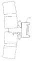
- FIG. 1Ais a plan view of a distractor made according an exemplary embodiment of the present invention.
- FIG. 1Bis an elevational view of the distractor of FIG. 1A ;
- FIG. 1Cis an anterior end view of the distractor of FIG. 1A ;
- FIG. 1Dis a side view of the distractor inserted in the disc space after distraction and a vertebrae immobilizing template fixing the positions of the distracted vertebral bodies;
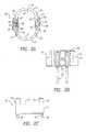
- FIG. 2Ais an anterior end view of the vertebrae immobilizing template made according an exemplary embodiment of the present invention
- FIG. 2Bis a plan view of the template of FIG. 2A ;
- FIG. 2Cis an elevational view of the template of FIG. 2A ;
- FIG. 3Ais a side view of a distractor/template handle made according to an exemplary embodiment of the present invention.
- FIG. 3Bis a distal end view of the handle of FIG. 3A ;
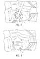
- FIG. 4Ais an exploded view a reamer assembly made according to an exemplary embodiment of the present invention.
- FIG. 4Bis a distal end view of a reamer sleeve of the reamer assembly of FIG. 4A ;
- FIG. 4Cis a side view of the reamer assembly depicting its use with the vertebrae immobilizing template, wherein the reamer sleeve is shown engaged with the vertebrae immobilizing template, and a reamer of the reamer assembly is shown disposed in the disc space and cutting the endplates of the vertebral bodies; and
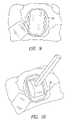
- FIGS. 5–12depict an exemplary method of using the instrument system of the present invention.
- the present inventionis an instrument system for preparing a disc space between adjacent vertebral bodies to restore the natural lordosis of the lumbar and cervical spine, so that a repair device of the type which prevents motion between the two adjacent vertebrae (commonly referred to as a fusion implant), or which permits motion between the two adjacent vertebral bodies (sometimes referred to as an artificial disc or artificial motion segment) can be inserted therein.
- the instrument systemmay comprise the following instruments: a series of distractors, one of which is shown in FIGS. 1A–1C (denoted by reference character 10 ), a vertebrae immobilizing template 50 as shown in FIGS. 2A–2C , a distractor/template handle 70 as shown in FIGS. 3A and 3B , and a reamer assembly as shown in FIG. 4 .
- each of the distractors in the seriesis constructed to provide a certain amount of interdiscal distraction that restores the natural lordosis of the lumbar and cervical spine.
- each distractor 10generally comprises a body section 11 forming an posterior end 12 of the distractor 10 and a connector section 13 forming an anterior end 14 of the distractor 10 .
- the body section 11includes a base portion 15 and a tapered portion 16 .
- the base portion 15is formed by parallel superior and inferior wall portions 17 , 18 separated by parallel side wall portions 19 , 20 .
- the tapered portion 16defines posterior converging superior and inferior wall portions 21 , 22 that respectively extend from the parallel superior and inferior wall portions 17 , 18 , and posterior converging side wall portions 23 , 24 that respectively extend from the parallel side wall portions 19 , 20 .
- the posterior converging superior, inferior, and side wall portions 21 , 22 , 23 , 24meet at a posterior wall 25 .
- the edges 26 where the posterior converging superior, inferior, and side wall portions 21 , 22 , 23 , 24 meet the posterior wall 25may be radiused.
- the posterior converging superior and/or inferior wall portions 21 , 22 of the tapered body portion 16 , adjacent the base body portion 15 ,may include one or more groove-like elements 27 .
- the groove-like elements 27may extend across the posterior converging superior and/or inferior wall portions 21 , 22 in a direction which is generally perpendicular to the longitudinal axis A L of the distractor 10 .
- the posterior converging superior and/or inferior wall portions 21 , 22may also include indicia 41 to indicate height, and/or cross-sectional size.
- the posterior converging superior and inferior wall portions 21 , 22define a taper angle ⁇ which matches the tapered portion 16 of the body section 11 to the implant lordosis.
- the taper angle ⁇ defined by the posterior converging superior and inferior wall portions 21 , 22may be about 7 degrees. It should be understood, however, that other taper angles ⁇ may be utilized, depending upon the implant lordosis and the natural lordosis of the disc space being operated on. Lordosis requires that the anterior height of the disc space be greater than the posterior height.
- the tapered body portion 16 of the distractor 10reestablishes such a disc space, and prepares a broad contact area for the repair device.
- the contact area provided by the distractors 10 of the present inventionis unlike the disc space resulting from prior art distractors.
- the connector section 13 of the distractor 10detachably couples the distractor/template handle 70 to the distractor 10 in a secure manner and aligns the template 50 with the distractor 10 .
- the connector section 13when viewed from its anterior end 14 as shown in FIG. 1C , has an elongated configuration formed by superior and inferior wall portions 28 , 29 that merge into curved side wall portions 30 , 31 .
- the superior, inferior, and side wall portions 28 , 29 , 30 , 31extend between a posterior flange wall 32 and a generally planar anterior wall 33 .
- the connector sectionfurther includes a female coupling member formed by a T-shape slot 34 .
- the T-shaped slot 34defines inwardly facing locking flanges 35 , 36 which cooperate with a correspondingly shaped male coupling member 73 disposed at the marginal distal end of distractor/template handle 70 to provide a bayonet coupling of the handle 70 to the distractor 10 .
- a chamfered pilot pin receiving bore 37extends from surface 38 of the slot 34 and terminates in the body section 11 of the distractor 10 .
- the pilot pin receiving bore 37is dimensioned to removably receive a pilot pin 78 formed at a distal-most end of the distractor/template handle 70 .
- the pilot pin 78 /pilot pin bore 37 arrangementaids in aligning the male coupling member 73 of the handle 70 with the anterior opening of connector section slot 34 of the distractor 10 .
- the coupling member 73can then be inserted into the slot 34 and rotated (about 90 degrees) to engage the locking flanges 35 , 36 .
- one or more detent elements 40are provided on surface(s) 39 of the slot 34 .
- the detent elements 40coact with a corresponding detent element(s) 77 formed on the male coupling member 73 of the handle 70 .
- the detent element(s) 40 provided in the slot 34may be spring-biased ball detent assemblies and the detent element(s) 77 formed on the male coupling member 73 may be indents.
- the vertebrae immobilizing template 50comprises an elongated sleeve member 51 , which defines a reamer sleeve abutment surface 62 and an elongated opening 52 that generally corresponds to the elongated configuration of the connector sections 13 of the distractors 10 .
- the sleeve member opening 52is dimensioned and configured so that the template 50 can be placed about any of the distractors 10 and is typically sized according to the cross-sectional size of the repair device to be used as will be explained further on.
- the sleeve member opening 52defines opposing inner superior/inferior surfaces 59 and opposing side inner surfaces 61 .
- Prong mounting ears 53are formed on opposing sides of the sleeve member 51 .
- Each mounting ear 53includes an posterior surface 54 and an anterior surface 55 .
- Spaced-apart prongs 56extend from the posterior surface 54 of the mounting ears 53 .
- the anterior surface 55 of each prong mounting ear 53includes a handle impaction recess 57 .
- the inner surfaces 59 of the sleeve member opening 52include recesses 60 that receive the opposing arms 75 of the male coupling member 73 of the handle 70 .
- One or more detent elements 58are disposed on the inner surface(s) 59 of the sleeve member opening 52 .
- the detent elements 40coact with the earlier described detent element(s) 77 of the male coupling member 73 of the handle, to couple the handle 70 to the template 50 .
- the detent element(s) 58may be spring-biased ball detent assemblies.
- the vertebrae immobilizing template 50is placed about the distractor 10 after distraction without removing the distractor 10 from the disc space, and the prongs 56 thereof are impacted into the distracted adjacent vertebral bodies to fix the positions.
- the prongs 56 of the template 50are impacted such that the mounting ear posterior surfaces 54 of the template 50 are approximately aligned in the same plane with the posterior flange wall 32 of the distractor 10 as shown in FIG. 1D .
- the template 50is then used for guiding the reamer assembly.
- the handle 70is used for inserting a distractor 10 between the vertebral bodies and tapping the distractor 10 into the disc space to distract the bodies.
- the handle 70is also used for removing the distractor 10 from the disc space.
- the handle 70is used for placing the template 50 about the distractor 10 while it is disposed in the disc space, and impacting the prongs 56 of the vertebrae immobilizing template 50 into the distracted adjacent vertebral bodies.
- the handle 70typically includes an elongated driver shaft 71 and a handle grip 72 having a diameter D H which may be greater than the diameter D s of the shaft 71 . Disposed at the distal end of the shaft 71 is the earlier described male coupling member 73 .
- the male coupling member 73may be a T-shape element formed by a cylindrical body 74 and the earlier described opposing arms 75 , the ends of which define arcuate end surfaces 76 .
- the end surfaces 76include the corresponding detent elements 77 which may be indents as described earlier, that are capable of coacting with the detent elements 40 , 58 of the distractors 10 and the template 50 .
- the pilot pin 78 described earlierextends from the male coupling member 73 to define the distal-most end of the handle 70 .
- the edge of the pilot pin 78may be beveled to aid insertion into the pilot pin receiving bore 37 of the distractor 10 .
- An annular impaction member 79is disposed at the base of the male coupling member body 74 and is attached thereto by spokes 80 .
- the impaction member 79engages the handle impaction recesses 57 in the anterior surface 55 of each prong mounting ear 53 of the vertebrae immobilizing template 50 .
- the handle grip 70may be provided with a knurled surface 81 or other means for facilitating secure manual gripping of the handle 70 .
- a proximal end 82 of the handle grip 81is typically provided with a convex surface 83 against which a mallet or other like device may be used to tap the handle 70 .
- the reamer assembly 90 shown in FIG. 4Acomprises an elongated reamer sleeve 92 and a series of differently dimensioned or sized reamers 94 (only one is shown).
- Each reamer 94includes a shaft-like body 95 having a frustoconical end-mill 98 defined at a distal end 96 thereof and a chuck-shaft 99 defined at a proximal end 97 thereof.
- a cylindrical stop member 100is disposed proximally to the end-mill 98 on the body 95 .
- the chuck-shaft 99enables the reamer 94 to be mounted in a chuck 110 of a reamer rotating device 109 , such as a drill.
- the frustoconical end-mill 98has a tapered profile that approximately matches the taper angle ⁇ of the distractors 10 .
- the exterior surface of the frustoconical end-mill 98typically includes a plurality of bone cutting elements 101 for cutting tissue from the opposing endplates of the distracted vertebral bodies.
- the bone cutting elements 101may be configured, in one exemplary embodiment, as longitudinal flutes. This construction enables the reamer 94 to simultaneously prepare the opposing endplates of the distracted adjacent vertebral bodies as it is passed across the endplates.
- the end-mills 98 of the reamers 94are each sized so as to controllably remove a specified amount of tissue off of the opposing endplates of the vertebral bodies.
- each reamer end-mill 98corresponds to the size of a corresponding distractor 10 .
- the particular reamer 94 selected for preparing the endplatesis based on the distractor 10 selected for distraction.
- Nonlinear geometriescan be accommodated through modifications to the shape of template 50 and reamer end-mill 98 .
- the sleeve 92includes a cylindrical body 102 that is dimensioned to rotatively receive the reamers 94 .
- the cylindrical body 102includes an enlarged cylindrical section 104 at a distal end 103 thereof and a chuck stop 106 at a proximal end 105 thereof.
- the enlarged cylindrical section 104includes a distal edge surface 107 for engaging the reamer sleeve abutment surface 62 of the template 50 .
- the distal edge surface 107includes reliefs 108 for clearing the mounting ears 53 of the template 50 .
- the sleeve 92operates to limit the depth of the reamer 94 travel into the disc space as the chuck 110 of the reamer rotating device 109 contacts the chuck stop 106 of the reamer sleeve 92 .
- Side-to-side travel of the reamer 94is limited by the cylindrical stop 100 on the reamer 94 , which engages the opposing side inner surfaces 61 of the template 50 .
- the instruments 10 , 50 , 70 , 90 of the systemare typically made from stainless steel.
- One of ordinary skill in the artwill of course appreciate that one or more of the instruments 10 , 50 , 70 , 90 may be made from any other suitable bio-compatible material.
- the following surgical techniqueillustrates the interaction of the instruments 10 , 50 , 70 , 90 of the instrument system of the present invention as used in the implantation of an exemplary fusion device, such as an alif device constructed from HEDROCEL®, which is available from Implex Corporation.
- surgeonmust decide which intervertebral levels to fuse. This may be done using a variety of diagnostic techniques, such as radiographs, MRI, discography, patient history, and physical examination.
- the patientis positioned in the supine position, with a pad under the lumbar spine to maintain lordosis.
- the surgeonmay choose either a supine position or a lateral decubitus position. In either case, a table should be used that accommodates both lateral and anterior-posterior radiographs.
- a vascular or general surgeonusually provides the exposure while the spine surgeon assists and then performs the fusion.
- the lumbar spineis exposed through a low transverse or paramedian incision while a retroperitoneal plane is developed.
- a midaxillary incision aligned over the level to be treatedit may be more appropriate to use a midaxillary incision aligned over the level to be treated.
- the device(s)are implanted in an anterior-posterior direction so that the retroperitoneal plane must be developed from the anterior direction.
- Standard general and/or vascular surgical instrumentsare used to perform the exposure down to the level(s) of the fusion. They are also used to maintain the exposure via the appropriate retractors.
- the exposureis completed when the anterior surface of the spine is exposed.
- needle(s)are inserted into the intervertebral disc as markers, and the location(s) determined by means of a C-arm anterior-posterior radiograph. If the needle is not along the midline, it should be repositioned and an additional radiograph taken to assure its proper location.
- Iliac crest autograftis harvested from the iliac crest. This can be done using standard techniques. Depending on the size and height of the device used, approximately 0.5 to 1.5 cc 3 of bone is required at each fusion level.
- the bone graftdoes not provide structural support but instead is used for its biological properties to stimulate bone formation.
- An annulotomyis performed using a scalpel to make a window in the annulus. It should be centered about the midline. It should be as long as the space to be occupied by the implant(s).
- an initial distractor 10is selected. It is assembled to the handle 70 .
- the pilot pin 78 on the handle 70fits within a receiving bore 37 on the anterior surface 38 of the distractor 10 .
- the handle 70is rotated to align the male coupling member 73 of the handle 70 with the slot 34 in the connector section 13 of the distractor 10 .
- the handle 70is advanced until the pilot pin 78 is fully engaged.
- the handle 70is rotated 90 degrees to engage the ball detents 40 that help hold the handle 70 in place relative to the distractor 10 .
- the distractor 10is placed into the interdiscal space, using the handle 70 to manipulate it.
- the distractor 10is inserted under intermittent lateral fluoroscopic/radiographic evaluation until the distractor 10 is appropriately seated posteriorly, a few millimeters anterior of the posterior border of the body.
- the distractors 10are changed until the appropriate height of the distractor 10 is determined.
- the height of the distractor 10is appropriate when the annulus is fully tensioned. Tensioning is checked by fully seating a distractor 10 and then pulling on the handle 70 to remove it. When the distractor 10 disengages easily, a larger distractor 10 should be placed. When the appropriate distractor 10 is determined and in place, the handle 70 is removed as shown in FIG. 6 .
- the cross sectional size of the deviceis determined from the grooves 27 on the superior and inferior surfaces 21 , 22 of the distractor 10 . These grooves 27 are visible from lateral fluoroscopy/radiograph. Each groove 27 corresponds to an implant cross section and to a template 50 size as well.
- the handle 70is assembled to the appropriately sized template 50 .
- Ball detents 58 of the template 50indicate the appropriate orientation of the handle 70 with respect to the template 50 .
- This assemblyis then placed over the distractor 10 and slid into place.
- a malletis used with the handle 70 to impact the template 50 into the two vertebral bodies.
- the prongs 56 on the template 50engage the adjacent vertebral bodies and hold the template 50 in place. Impaction continues until the template 50 bottoms out on the distractor 10 . This fixes the position of the template 50 relative to the posterior edge of the distractor 10 .
- the handle 70is then rotated 90 degrees.
- the ball detents 40 from the distractor 10engage the handle 70 , indicating the appropriate position.
- the distractor 10is then withdrawn, leaving the template 50 .
- the endplatesare then prepared using the reamer assembly 90 having an appropriately sized one of the reamers 94 installed in the reamer sleeve 92 .
- the reamer assembly 90is used to remove a fixed amount of bone off of the endplates, based on the fit of the initial distractor 10 .
- the reamer sleeve 92prevents the rotation of the reamer 94 from catching adjacent tissue.
- the sleeve 92also limits the penetration of the reamer 94 into the disc space as mentioned earlier.
- the reamer assembly 90mates with the template 50 .
- the template 50limits the lateral motion of the reamer assembly 90 .
- the template 50 and reamer assembly 90result in removal of approximately 1.5 mm from each endplate.
- the reamer assembly 90is then removed as shown in FIG. 9 .
- One Hedrocel ALIF deviceis used at a single level.
- the proper implant sizeis determined by the insertion depth of the distractor 10 and the distractor height used.
- Placement of the implant 120is typically along the midline. On a sterile table, the hole(s) of the appropriately sized implant 120 is stuffed with the already harvested autologous bone. The implant 120 is then placed on an inserter 121 . As shown in FIG. 10 , the implant 120 is passed through the template 50 , into the space and the inserter 121 removed. The implant 120 is fully seated using a tamp 122 as shown in FIG. 11 .
- the implant's heightis sized so that it will further distract the vertebral bodies by approximately 1 ⁇ 2 mm beyond the distraction of the initial device.
- lateral and A/P radiographsmay be taken to assure proper implant placement. Once proper placement is assured, the template 50 is removed as shown in FIG. 12 , using the handle 70 (not shown).
Landscapes
- Health & Medical Sciences (AREA)
- Surgery (AREA)
- Orthopedic Medicine & Surgery (AREA)
- Life Sciences & Earth Sciences (AREA)
- Biomedical Technology (AREA)
- Nuclear Medicine, Radiotherapy & Molecular Imaging (AREA)
- Oral & Maxillofacial Surgery (AREA)
- Engineering & Computer Science (AREA)
- Dentistry (AREA)
- Heart & Thoracic Surgery (AREA)
- Medical Informatics (AREA)
- Molecular Biology (AREA)
- Animal Behavior & Ethology (AREA)
- General Health & Medical Sciences (AREA)
- Public Health (AREA)
- Veterinary Medicine (AREA)
- Prostheses (AREA)
Abstract
Description
RL−SL=DL+TL
where RL is the length of the reamer94 (not including the chuck-shaft99), SL is the length of the
Claims (29)
Priority Applications (2)
| Application Number | Priority Date | Filing Date | Title |
|---|---|---|---|
| US10/035,863US7153304B2 (en) | 2000-12-29 | 2001-12-31 | Instrument system for preparing a disc space between adjacent vertebral bodies to receive a repair device |
| US11/469,791US20070016213A1 (en) | 2000-12-29 | 2006-09-01 | Instrument system for preparing a disc space between adjacent vertebral bodies to receive a repair device |
Applications Claiming Priority (2)
| Application Number | Priority Date | Filing Date | Title |
|---|---|---|---|
| US25926200P | 2000-12-29 | 2000-12-29 | |
| US10/035,863US7153304B2 (en) | 2000-12-29 | 2001-12-31 | Instrument system for preparing a disc space between adjacent vertebral bodies to receive a repair device |
Related Child Applications (1)
| Application Number | Title | Priority Date | Filing Date |
|---|---|---|---|
| US11/469,791DivisionUS20070016213A1 (en) | 2000-12-29 | 2006-09-01 | Instrument system for preparing a disc space between adjacent vertebral bodies to receive a repair device |
Publications (2)
| Publication Number | Publication Date |
|---|---|
| US20020161366A1 US20020161366A1 (en) | 2002-10-31 |
| US7153304B2true US7153304B2 (en) | 2006-12-26 |
Family
ID=26712567
Family Applications (2)
| Application Number | Title | Priority Date | Filing Date |
|---|---|---|---|
| US10/035,863Expired - LifetimeUS7153304B2 (en) | 2000-12-29 | 2001-12-31 | Instrument system for preparing a disc space between adjacent vertebral bodies to receive a repair device |
| US11/469,791AbandonedUS20070016213A1 (en) | 2000-12-29 | 2006-09-01 | Instrument system for preparing a disc space between adjacent vertebral bodies to receive a repair device |
Family Applications After (1)
| Application Number | Title | Priority Date | Filing Date |
|---|---|---|---|
| US11/469,791AbandonedUS20070016213A1 (en) | 2000-12-29 | 2006-09-01 | Instrument system for preparing a disc space between adjacent vertebral bodies to receive a repair device |
Country Status (1)
| Country | Link |
|---|---|
| US (2) | US7153304B2 (en) |
Cited By (73)
| Publication number | Priority date | Publication date | Assignee | Title |
|---|---|---|---|---|
| US20050055029A1 (en)* | 2003-09-10 | 2005-03-10 | Sdgi Holdings, Inc. | Artificial spinal discs and associated implantation instruments and methods |
| US20060195109A1 (en)* | 2000-02-22 | 2006-08-31 | Mcgahan Thomas V | Instruments and techniques for disc space preparation |
| US20060217731A1 (en)* | 2005-03-28 | 2006-09-28 | Sdgi Holdings, Inc. | X-ray and fluoroscopic visualization slots |
| US20080221586A1 (en)* | 2007-02-09 | 2008-09-11 | Alphatec Spine, Inc. | Curviliner spinal access method and device |
| US20080234684A1 (en)* | 2007-02-08 | 2008-09-25 | Warsaw Orthopedic, Inc. | Instruments and techniques for guiding instruments to a spinal column |
| US20090043340A1 (en)* | 2007-08-07 | 2009-02-12 | Holland Surgical Innovations, Inc. | Implantable bone plate system and related method for spinal repair |
| US7544208B1 (en) | 2004-05-03 | 2009-06-09 | Theken Spine, Llc | Adjustable corpectomy apparatus |
| US20090312611A1 (en)* | 2005-06-17 | 2009-12-17 | Vycor Medical Llc | Surgical Access Methods For Use With Delicate Tissues |
| US20100022844A1 (en)* | 2005-06-22 | 2010-01-28 | Mangiardi John R | Surgical Access Instruments for Use with Spinal or Orthopedic Surgery |
| US7666226B2 (en) | 2005-08-16 | 2010-02-23 | Benvenue Medical, Inc. | Spinal tissue distraction devices |
| US7708780B2 (en) | 2003-03-06 | 2010-05-04 | Spinecore, Inc. | Instrumentation and methods for use in implanting a cervical disc replacement device |
| US20100130980A1 (en)* | 2002-11-12 | 2010-05-27 | Jansen Keith E | Serratome vertebral cortical endplate cutter |
| USD623296S1 (en)* | 2009-07-06 | 2010-09-07 | Globus Medical, Inc. | Spinous process spacer |
| USD623297S1 (en)* | 2009-07-06 | 2010-09-07 | Globus Medical, Inc. | Spinous process spacer |
| US20100262200A1 (en)* | 1998-04-09 | 2010-10-14 | Ray Iii Eddie F | Methods and instrumentation for vertebral interbody fusion |
| USD629903S1 (en)* | 2008-03-26 | 2010-12-28 | Corin Limited | Prosthesis stem |
| US7918876B2 (en) | 2003-03-24 | 2011-04-05 | Theken Spine, Llc | Spinal implant adjustment device |
| US8100972B1 (en) | 2007-07-02 | 2012-01-24 | Theken Spine, Llc | Spinal cage having deployable member |
| US8163021B2 (en) | 2007-11-27 | 2012-04-24 | Transcorp, Inc. | Methods and systems for repairing an intervertebral disc using a transcorporal approach |
| US20120116457A1 (en)* | 2010-11-06 | 2012-05-10 | Limited Liability Company; | Stabilizer for assisting stabilization of a spinal implant and method of using the stabilizer |
| US8267997B2 (en) | 2007-11-12 | 2012-09-18 | Theken Spine, Llc | Vertebral interbody compression implant |
| US8277507B2 (en) | 2002-04-12 | 2012-10-02 | Spinecore, Inc. | Spacerless artificial disc replacements |
| US8292958B1 (en) | 2007-07-02 | 2012-10-23 | Theken Spine, Llc | Spinal cage having deployable member |
| US8323320B2 (en) | 2007-09-13 | 2012-12-04 | Transcorp, Inc. | Transcorporeal spinal decompression and repair system and related method |
| US8366773B2 (en) | 2005-08-16 | 2013-02-05 | Benvenue Medical, Inc. | Apparatus and method for treating bone |
| US8425569B2 (en) | 2010-05-19 | 2013-04-23 | Transcorp, Inc. | Implantable vertebral frame systems and related methods for spinal repair |
| US8430882B2 (en) | 2007-09-13 | 2013-04-30 | Transcorp, Inc. | Transcorporeal spinal decompression and repair systems and related methods |
| US8454617B2 (en) | 2005-08-16 | 2013-06-04 | Benvenue Medical, Inc. | Devices for treating the spine |
| US8470041B2 (en) | 2002-04-12 | 2013-06-25 | Spinecore, Inc. | Two-component artificial disc replacements |
| US8535327B2 (en) | 2009-03-17 | 2013-09-17 | Benvenue Medical, Inc. | Delivery apparatus for use with implantable medical devices |
| US8545562B1 (en) | 2007-07-02 | 2013-10-01 | Theken Spine, Llc | Deployable member for use with an intervertebral cage |
| US8579911B2 (en) | 2008-01-18 | 2013-11-12 | Spinecore, Inc. | Instruments and methods for inserting artificial intervertebral implants |
| US8591583B2 (en) | 2005-08-16 | 2013-11-26 | Benvenue Medical, Inc. | Devices for treating the spine |
| US8709054B2 (en) | 2007-08-07 | 2014-04-29 | Transcorp, Inc. | Implantable vertebral frame systems and related methods for spinal repair |
| US8777959B2 (en) | 2005-05-27 | 2014-07-15 | Spinecore, Inc. | Intervertebral disc and insertion methods therefor |
| US8814873B2 (en) | 2011-06-24 | 2014-08-26 | Benvenue Medical, Inc. | Devices and methods for treating bone tissue |
| US8864829B1 (en) | 2007-07-02 | 2014-10-21 | Theken Spine, Llc | Spinal cage having deployable member |
| US9204906B2 (en) | 2009-10-22 | 2015-12-08 | Nuvasive, Inc. | Posterior cervical fusion system and techniques |
| US9216015B2 (en) | 2004-10-28 | 2015-12-22 | Vycor Medical, Inc. | Apparatus and methods for performing brain surgery |
| US9737287B2 (en) | 2014-05-13 | 2017-08-22 | Vycor Medical, Inc. | Guidance system mounts for surgical introducers |
| US9788963B2 (en) | 2003-02-14 | 2017-10-17 | DePuy Synthes Products, Inc. | In-situ formed intervertebral fusion device and method |
| US10085783B2 (en) | 2013-03-14 | 2018-10-02 | Izi Medical Products, Llc | Devices and methods for treating bone tissue |
| US10098674B2 (en) | 2009-10-22 | 2018-10-16 | Nuvasive, Inc. | System and method for posterior cervical fusion |
| US10342674B2 (en) | 2007-07-02 | 2019-07-09 | Theken Spine, Llc | Spinal cage having deployable member |
| US10376258B2 (en) | 2016-11-07 | 2019-08-13 | Vycor Medical, Inc. | Surgical introducer with guidance system receptacle |
| US10543016B2 (en) | 2016-11-07 | 2020-01-28 | Vycor Medical, Inc. | Surgical introducer with guidance system receptacle |
| US10888433B2 (en) | 2016-12-14 | 2021-01-12 | DePuy Synthes Products, Inc. | Intervertebral implant inserter and related methods |
| US10940016B2 (en) | 2017-07-05 | 2021-03-09 | Medos International Sarl | Expandable intervertebral fusion cage |
| US10966840B2 (en) | 2010-06-24 | 2021-04-06 | DePuy Synthes Products, Inc. | Enhanced cage insertion assembly |
| US10973652B2 (en) | 2007-06-26 | 2021-04-13 | DePuy Synthes Products, Inc. | Highly lordosed fusion cage |
| US11273050B2 (en) | 2006-12-07 | 2022-03-15 | DePuy Synthes Products, Inc. | Intervertebral implant |
| US11344424B2 (en) | 2017-06-14 | 2022-05-31 | Medos International Sarl | Expandable intervertebral implant and related methods |
| US11426290B2 (en) | 2015-03-06 | 2022-08-30 | DePuy Synthes Products, Inc. | Expandable intervertebral implant, system, kit and method |
| US11426286B2 (en) | 2020-03-06 | 2022-08-30 | Eit Emerging Implant Technologies Gmbh | Expandable intervertebral implant |
| US11446156B2 (en) | 2018-10-25 | 2022-09-20 | Medos International Sarl | Expandable intervertebral implant, inserter instrument, and related methods |
| US11446155B2 (en) | 2017-05-08 | 2022-09-20 | Medos International Sarl | Expandable cage |
| US11452607B2 (en) | 2010-10-11 | 2022-09-27 | DePuy Synthes Products, Inc. | Expandable interspinous process spacer implant |
| US11497619B2 (en) | 2013-03-07 | 2022-11-15 | DePuy Synthes Products, Inc. | Intervertebral implant |
| US11510788B2 (en) | 2016-06-28 | 2022-11-29 | Eit Emerging Implant Technologies Gmbh | Expandable, angularly adjustable intervertebral cages |
| US11596522B2 (en) | 2016-06-28 | 2023-03-07 | Eit Emerging Implant Technologies Gmbh | Expandable and angularly adjustable intervertebral cages with articulating joint |
| US11602438B2 (en) | 2008-04-05 | 2023-03-14 | DePuy Synthes Products, Inc. | Expandable intervertebral implant |
| US11607321B2 (en) | 2009-12-10 | 2023-03-21 | DePuy Synthes Products, Inc. | Bellows-like expandable interbody fusion cage |
| US11612491B2 (en) | 2009-03-30 | 2023-03-28 | DePuy Synthes Products, Inc. | Zero profile spinal fusion cage |
| US11654033B2 (en) | 2010-06-29 | 2023-05-23 | DePuy Synthes Products, Inc. | Distractible intervertebral implant |
| US11737881B2 (en) | 2008-01-17 | 2023-08-29 | DePuy Synthes Products, Inc. | Expandable intervertebral implant and associated method of manufacturing the same |
| US11752009B2 (en) | 2021-04-06 | 2023-09-12 | Medos International Sarl | Expandable intervertebral fusion cage |
| US11850160B2 (en) | 2021-03-26 | 2023-12-26 | Medos International Sarl | Expandable lordotic intervertebral fusion cage |
| US11911287B2 (en) | 2010-06-24 | 2024-02-27 | DePuy Synthes Products, Inc. | Lateral spondylolisthesis reduction cage |
| USRE49973E1 (en) | 2013-02-28 | 2024-05-21 | DePuy Synthes Products, Inc. | Expandable intervertebral implant, system, kit and method |
| US12090064B2 (en) | 2022-03-01 | 2024-09-17 | Medos International Sarl | Stabilization members for expandable intervertebral implants, and related systems and methods |
| US12178469B2 (en) | 2016-11-07 | 2024-12-31 | Vycor Medical Inc. | Surgical introducer with guidance system receptacle |
| US12186201B2 (en) | 2007-07-02 | 2025-01-07 | Theken Spine, Llc | Spinal cage having deployable member |
| US12440346B2 (en) | 2023-03-31 | 2025-10-14 | DePuy Synthes Products, Inc. | Expandable intervertebral implant |
Families Citing this family (28)
| Publication number | Priority date | Publication date | Assignee | Title |
|---|---|---|---|---|
| FR2767675B1 (en) | 1997-08-26 | 1999-12-03 | Materiel Orthopedique En Abreg | INTERSOMATIC IMPLANT AND ANCILLARY OF PREPARATION SUITABLE FOR ALLOWING ITS POSITION |
| CA2495404C (en) | 2002-08-15 | 2011-05-03 | Justin K. Coppes | Intervertebral disc implant |
| EP1542626B1 (en) | 2002-08-15 | 2012-09-26 | Synthes GmbH | Controlled artificial intervertebral disc implant |
| US7125425B2 (en) | 2002-10-21 | 2006-10-24 | Sdgi Holdings, Inc. | Systems and techniques for restoring and maintaining intervertebral anatomy |
| US7063725B2 (en) | 2002-10-21 | 2006-06-20 | Sdgi Holdings, Inc. | Systems and techniques for restoring and maintaining intervertebral anatomy |
| DE10253170A1 (en)* | 2002-11-14 | 2004-06-03 | Sepitec Foundation | Implant used in procedures for stiffening the vertebral column consists of a compression-resistant hollow body made from two open receptacles which are pressed apart with insertion of filler material |
| BRPI0408872A (en)* | 2003-03-31 | 2006-04-11 | Depuy Spine Inc | method and apparatus for inserting artificial discs |
| US8123757B2 (en) | 2003-12-31 | 2012-02-28 | Depuy Spine, Inc. | Inserter instrument and implant clip |
| US7771479B2 (en) | 2004-01-09 | 2010-08-10 | Warsaw Orthopedic, Inc. | Dual articulating spinal device and method |
| US20050171608A1 (en) | 2004-01-09 | 2005-08-04 | Sdgi Holdings, Inc. | Centrally articulating spinal device and method |
| US20050171610A1 (en)* | 2004-01-09 | 2005-08-04 | Sdgi Holdings, Inc. | Mobile bearing spinal device and method |
| US20060036261A1 (en)* | 2004-08-13 | 2006-02-16 | Stryker Spine | Insertion guide for a spinal implant |
| US8298235B2 (en)* | 2004-09-30 | 2012-10-30 | Depuy Spine, Inc. | Instrument and method for the insertion and alignment of an intervertebral implant |
| US20070055373A1 (en) | 2005-09-08 | 2007-03-08 | Zimmer Spine, Inc. | Facet replacement/spacing and flexible spinal stabilization |
| US7867279B2 (en) | 2006-01-23 | 2011-01-11 | Depuy Spine, Inc. | Intervertebral disc prosthesis |
| US7811326B2 (en) | 2006-01-30 | 2010-10-12 | Warsaw Orthopedic Inc. | Posterior joint replacement device |
| US7635389B2 (en) | 2006-01-30 | 2009-12-22 | Warsaw Orthopedic, Inc. | Posterior joint replacement device |
| US20070203500A1 (en)* | 2006-02-28 | 2007-08-30 | Vermillion Technologies, Llc | Apparatus and method of shaping an intervertebral space |
| US8303601B2 (en) | 2006-06-07 | 2012-11-06 | Stryker Spine | Collet-activated distraction wedge inserter |
| US8579910B2 (en) | 2007-05-18 | 2013-11-12 | DePuy Synthes Products, LLC | Insertion blade assembly and method of use |
| US8864832B2 (en) | 2007-06-20 | 2014-10-21 | Hh Spinal Llc | Posterior total joint replacement |
| US10821003B2 (en) | 2007-06-20 | 2020-11-03 | 3Spline Sezc | Spinal osteotomy |
| CA2688437C (en) | 2007-06-29 | 2015-12-22 | Synthes Usa, Llc | Flexible chain implants and instrumentation |
| US20100010548A1 (en)* | 2008-07-11 | 2010-01-14 | Elias Humberto Hermida Ochoa | Instruments and Method of Use for Minimally Invasive Spine Surgery in Interspine Space Through Only One Side |
| EP2400931B1 (en)* | 2009-02-25 | 2015-10-28 | Spinewelding AG | Spine stabilization device and kit for its implantation |
| US8906033B2 (en) | 2009-03-30 | 2014-12-09 | DePuy Synthes Products, LLC | Cervical motion disc inserter |
| CN113349878B (en)* | 2021-04-30 | 2023-04-28 | 四川大学华西医院 | Operation guide plate for anterior cervical vertebral body osteotomy and design method thereof |
| US12409046B2 (en) | 2022-04-12 | 2025-09-09 | 3Spine, Inc. | Total spinal joint systems with motion moderators |
Citations (22)
| Publication number | Priority date | Publication date | Assignee | Title |
|---|---|---|---|---|
| US4501269A (en) | 1981-12-11 | 1985-02-26 | Washington State University Research Foundation, Inc. | Process for fusing bone joints |
| US4878915A (en) | 1987-01-22 | 1989-11-07 | Brantigan John W | Surgical prosthetic implant facilitating vertebral interbody fusion |
| US5015247A (en) | 1988-06-13 | 1991-05-14 | Michelson Gary K | Threaded spinal implant |
| US5026373A (en) | 1988-10-17 | 1991-06-25 | Surgical Dynamics, Inc. | Surgical method and apparatus for fusing adjacent bone structures |
| US5055104A (en) | 1989-11-06 | 1991-10-08 | Surgical Dynamics, Inc. | Surgically implanting threaded fusion cages between adjacent low-back vertebrae by an anterior approach |
| US5308350A (en)* | 1990-04-11 | 1994-05-03 | Mikhail Michael W E | Femoral distractor for use in knee surgery |
| US5484437A (en)* | 1988-06-13 | 1996-01-16 | Michelson; Gary K. | Apparatus and method of inserting spinal implants |
| US5722977A (en)* | 1996-01-24 | 1998-03-03 | Danek Medical, Inc. | Method and means for anterior lumbar exact cut with quadrilateral osteotome and precision guide/spacer |
| US5797909A (en) | 1988-06-13 | 1998-08-25 | Michelson; Gary Karlin | Apparatus for inserting spinal implants |
| US5947971A (en)* | 1993-02-10 | 1999-09-07 | Sulzer Spine-Tech Inc. | Spinal stabilization surgical apparatus |
| US5993453A (en) | 1997-10-15 | 1999-11-30 | Huntington Medical Research Institutes | Controlled-depth bone cutter |
| US6030390A (en)* | 1999-01-08 | 2000-02-29 | Mehdizadeh; Hamid M. | Disc space spreader |
| US6042582A (en) | 1997-05-20 | 2000-03-28 | Ray; Charles D. | Instrumentation and method for facilitating insertion of spinal implant |
| US6059790A (en) | 1997-08-29 | 2000-05-09 | Sulzer Spine-Tech Inc. | Apparatus and method for spinal stabilization |
| US6063088A (en) | 1997-03-24 | 2000-05-16 | United States Surgical Corporation | Method and instrumentation for implant insertion |
| US6113602A (en) | 1999-03-26 | 2000-09-05 | Sulzer Spine-Tech Inc. | Posterior spinal instrument guide and method |
| US6210412B1 (en)* | 1988-06-13 | 2001-04-03 | Gary Karlin Michelson | Method for inserting frusto-conical interbody spinal fusion implants |
| US6224599B1 (en)* | 1999-05-19 | 2001-05-01 | Matthew G. Baynham | Viewable wedge distractor device |
| US6440139B2 (en)* | 1996-07-31 | 2002-08-27 | Gary K. Michelson | Milling instrumentation and method for preparing a space between adjacent vertebral bodies |
| US6589247B2 (en)* | 1999-10-15 | 2003-07-08 | Sdgi Holdings, Inc. | Distraction instrument with fins for maintaining insertion location |
| US6648895B2 (en)* | 2000-02-04 | 2003-11-18 | Sdgi Holdings, Inc. | Methods and instrumentation for vertebral interbody fusion |
| US6824565B2 (en)* | 2000-09-08 | 2004-11-30 | Nabil L. Muhanna | System and methods for inserting a vertebral spacer |
- 2001
- 2001-12-31USUS10/035,863patent/US7153304B2/ennot_activeExpired - Lifetime
- 2006
- 2006-09-01USUS11/469,791patent/US20070016213A1/ennot_activeAbandoned
Patent Citations (25)
| Publication number | Priority date | Publication date | Assignee | Title |
|---|---|---|---|---|
| US4501269A (en) | 1981-12-11 | 1985-02-26 | Washington State University Research Foundation, Inc. | Process for fusing bone joints |
| US4878915A (en) | 1987-01-22 | 1989-11-07 | Brantigan John W | Surgical prosthetic implant facilitating vertebral interbody fusion |
| US5015247A (en) | 1988-06-13 | 1991-05-14 | Michelson Gary K | Threaded spinal implant |
| US6210412B1 (en)* | 1988-06-13 | 2001-04-03 | Gary Karlin Michelson | Method for inserting frusto-conical interbody spinal fusion implants |
| US6096038A (en) | 1988-06-13 | 2000-08-01 | Michelson; Gary Karlin | Apparatus for inserting spinal implants |
| US5484437A (en)* | 1988-06-13 | 1996-01-16 | Michelson; Gary K. | Apparatus and method of inserting spinal implants |
| US5505732A (en) | 1988-06-13 | 1996-04-09 | Michelson; Gary K. | Apparatus and method of inserting spinal implants |
| US6080155A (en) | 1988-06-13 | 2000-06-27 | Michelson; Gary Karlin | Method of inserting and preloading spinal implants |
| US5797909A (en) | 1988-06-13 | 1998-08-25 | Michelson; Gary Karlin | Apparatus for inserting spinal implants |
| US5026373A (en) | 1988-10-17 | 1991-06-25 | Surgical Dynamics, Inc. | Surgical method and apparatus for fusing adjacent bone structures |
| US5055104A (en) | 1989-11-06 | 1991-10-08 | Surgical Dynamics, Inc. | Surgically implanting threaded fusion cages between adjacent low-back vertebrae by an anterior approach |
| US5308350A (en)* | 1990-04-11 | 1994-05-03 | Mikhail Michael W E | Femoral distractor for use in knee surgery |
| US5947971A (en)* | 1993-02-10 | 1999-09-07 | Sulzer Spine-Tech Inc. | Spinal stabilization surgical apparatus |
| US5722977A (en)* | 1996-01-24 | 1998-03-03 | Danek Medical, Inc. | Method and means for anterior lumbar exact cut with quadrilateral osteotome and precision guide/spacer |
| US6440139B2 (en)* | 1996-07-31 | 2002-08-27 | Gary K. Michelson | Milling instrumentation and method for preparing a space between adjacent vertebral bodies |
| US6063088A (en) | 1997-03-24 | 2000-05-16 | United States Surgical Corporation | Method and instrumentation for implant insertion |
| US6042582A (en) | 1997-05-20 | 2000-03-28 | Ray; Charles D. | Instrumentation and method for facilitating insertion of spinal implant |
| US6059790A (en) | 1997-08-29 | 2000-05-09 | Sulzer Spine-Tech Inc. | Apparatus and method for spinal stabilization |
| US5993453A (en) | 1997-10-15 | 1999-11-30 | Huntington Medical Research Institutes | Controlled-depth bone cutter |
| US6030390A (en)* | 1999-01-08 | 2000-02-29 | Mehdizadeh; Hamid M. | Disc space spreader |
| US6113602A (en) | 1999-03-26 | 2000-09-05 | Sulzer Spine-Tech Inc. | Posterior spinal instrument guide and method |
| US6224599B1 (en)* | 1999-05-19 | 2001-05-01 | Matthew G. Baynham | Viewable wedge distractor device |
| US6589247B2 (en)* | 1999-10-15 | 2003-07-08 | Sdgi Holdings, Inc. | Distraction instrument with fins for maintaining insertion location |
| US6648895B2 (en)* | 2000-02-04 | 2003-11-18 | Sdgi Holdings, Inc. | Methods and instrumentation for vertebral interbody fusion |
| US6824565B2 (en)* | 2000-09-08 | 2004-11-30 | Nabil L. Muhanna | System and methods for inserting a vertebral spacer |
Cited By (190)
| Publication number | Priority date | Publication date | Assignee | Title |
|---|---|---|---|---|
| US20100262200A1 (en)* | 1998-04-09 | 2010-10-14 | Ray Iii Eddie F | Methods and instrumentation for vertebral interbody fusion |
| US20060195109A1 (en)* | 2000-02-22 | 2006-08-31 | Mcgahan Thomas V | Instruments and techniques for disc space preparation |
| US8206397B2 (en)* | 2000-02-22 | 2012-06-26 | Warsaw Orthopedic | Instruments and techniques for disc space preparation |
| US10271956B2 (en) | 2002-04-12 | 2019-04-30 | Spinecore, Inc. | Spacerless artificial disc replacements |
| US8470041B2 (en) | 2002-04-12 | 2013-06-25 | Spinecore, Inc. | Two-component artificial disc replacements |
| US8679182B2 (en) | 2002-04-12 | 2014-03-25 | Spinecore, Inc. | Spacerless artificial disc replacements |
| US8277507B2 (en) | 2002-04-12 | 2012-10-02 | Spinecore, Inc. | Spacerless artificial disc replacements |
| US8801789B2 (en) | 2002-04-12 | 2014-08-12 | Spinecore, Inc. | Two-component artificial disc replacements |
| US9198773B2 (en) | 2002-04-12 | 2015-12-01 | Spinecore, Inc. | Spacerless artificial disc replacements |
| US10786363B2 (en) | 2002-04-12 | 2020-09-29 | Spinecore, Inc. | Spacerless artificial disc replacements |
| US8262660B2 (en)* | 2002-11-12 | 2012-09-11 | Alphatec Spine, Inc. | Serratome vertebral cortical endplate cutter |
| US20100130980A1 (en)* | 2002-11-12 | 2010-05-27 | Jansen Keith E | Serratome vertebral cortical endplate cutter |
| US9925060B2 (en) | 2003-02-14 | 2018-03-27 | DePuy Synthes Products, Inc. | In-situ formed intervertebral fusion device and method |
| US9801729B2 (en) | 2003-02-14 | 2017-10-31 | DePuy Synthes Products, Inc. | In-situ formed intervertebral fusion device and method |
| US11432938B2 (en) | 2003-02-14 | 2022-09-06 | DePuy Synthes Products, Inc. | In-situ intervertebral fusion device and method |
| US10376372B2 (en) | 2003-02-14 | 2019-08-13 | DePuy Synthes Products, Inc. | In-situ formed intervertebral fusion device and method |
| US10786361B2 (en) | 2003-02-14 | 2020-09-29 | DePuy Synthes Products, Inc. | In-situ formed intervertebral fusion device and method |
| US10085843B2 (en) | 2003-02-14 | 2018-10-02 | DePuy Synthes Products, Inc. | In-situ formed intervertebral fusion device and method |
| US10575959B2 (en) | 2003-02-14 | 2020-03-03 | DePuy Synthes Products, Inc. | In-situ formed intervertebral fusion device and method |
| US10492918B2 (en) | 2003-02-14 | 2019-12-03 | DePuy Synthes Products, Inc. | In-situ formed intervertebral fusion device and method |
| US10583013B2 (en) | 2003-02-14 | 2020-03-10 | DePuy Synthes Products, Inc. | In-situ formed intervertebral fusion device and method |
| US10433971B2 (en) | 2003-02-14 | 2019-10-08 | DePuy Synthes Products, Inc. | In-situ formed intervertebral fusion device and method |
| US10420651B2 (en) | 2003-02-14 | 2019-09-24 | DePuy Synthes Products, Inc. | In-situ formed intervertebral fusion device and method |
| US11207187B2 (en) | 2003-02-14 | 2021-12-28 | DePuy Synthes Products, Inc. | In-situ formed intervertebral fusion device and method |
| US9814589B2 (en) | 2003-02-14 | 2017-11-14 | DePuy Synthes Products, Inc. | In-situ formed intervertebral fusion device and method |
| US9814590B2 (en) | 2003-02-14 | 2017-11-14 | DePuy Synthes Products, Inc. | In-situ formed intervertebral fusion device and method |
| US9808351B2 (en) | 2003-02-14 | 2017-11-07 | DePuy Synthes Products, Inc. | In-situ formed intervertebral fusion device and method |
| US10639164B2 (en) | 2003-02-14 | 2020-05-05 | DePuy Synthes Products, Inc. | In-situ formed intervertebral fusion device and method |
| US9788963B2 (en) | 2003-02-14 | 2017-10-17 | DePuy Synthes Products, Inc. | In-situ formed intervertebral fusion device and method |
| US10555817B2 (en) | 2003-02-14 | 2020-02-11 | DePuy Synthes Products, Inc. | In-situ formed intervertebral fusion device and method |
| US10405986B2 (en) | 2003-02-14 | 2019-09-10 | DePuy Synthes Products, Inc. | In-situ formed intervertebral fusion device and method |
| US11096794B2 (en) | 2003-02-14 | 2021-08-24 | DePuy Synthes Products, Inc. | In-situ formed intervertebral fusion device and method |
| US8109979B2 (en) | 2003-03-06 | 2012-02-07 | Spinecore, Inc. | Instrumentation and methods for use in implanting a cervical disc replacement device |
| US8231628B2 (en) | 2003-03-06 | 2012-07-31 | Spinecore, Inc. | Instrumentation and methods for use in implanting a cervical disc replacement device |
| US7708780B2 (en) | 2003-03-06 | 2010-05-04 | Spinecore, Inc. | Instrumentation and methods for use in implanting a cervical disc replacement device |
| US7918876B2 (en) | 2003-03-24 | 2011-04-05 | Theken Spine, Llc | Spinal implant adjustment device |
| US20050055029A1 (en)* | 2003-09-10 | 2005-03-10 | Sdgi Holdings, Inc. | Artificial spinal discs and associated implantation instruments and methods |
| US7794465B2 (en)* | 2003-09-10 | 2010-09-14 | Warsaw Orthopedic, Inc. | Artificial spinal discs and associated implantation instruments and methods |
| US7544208B1 (en) | 2004-05-03 | 2009-06-09 | Theken Spine, Llc | Adjustable corpectomy apparatus |
| US9216015B2 (en) | 2004-10-28 | 2015-12-22 | Vycor Medical, Inc. | Apparatus and methods for performing brain surgery |
| US9386974B2 (en) | 2004-10-28 | 2016-07-12 | Vycor Medical, Inc. | Apparatus and methods for performing brain surgery |
| US9968415B2 (en) | 2004-10-28 | 2018-05-15 | Vycor Medical, Inc. | Apparatus and methods for performing brain surgery |
| US9968414B2 (en) | 2004-10-28 | 2018-05-15 | Vycor Medical, Inc. | Apparatus and methods for performing brain surgery |
| US20060217731A1 (en)* | 2005-03-28 | 2006-09-28 | Sdgi Holdings, Inc. | X-ray and fluoroscopic visualization slots |
| US9782272B2 (en) | 2005-05-27 | 2017-10-10 | Spinecore, Inc. | Intervertebral disc and insertion methods therefor |
| US9095451B2 (en) | 2005-05-27 | 2015-08-04 | Spinecore, Inc. | Intervertebral disc and insertion methods therefor |
| US11642231B2 (en) | 2005-05-27 | 2023-05-09 | Howmedica Osteonics Corp. | Intervertebral disc and insertion methods therefor |
| US10213322B2 (en) | 2005-05-27 | 2019-02-26 | Spinecore, Inc. | Intervertebral disc and insertion methods therefor |
| US10835389B2 (en) | 2005-05-27 | 2020-11-17 | Howmedica Osteonics Corp. | Intervertebral disc and insertion methods therefor |
| US9226837B2 (en) | 2005-05-27 | 2016-01-05 | Spinecore, Inc. | Intervertebral disc and insertion methods therefor |
| US10245154B2 (en) | 2005-05-27 | 2019-04-02 | Spinecore, Inc. | Instruments and methods for inserting artificial intervertebral implants |
| US8777959B2 (en) | 2005-05-27 | 2014-07-15 | Spinecore, Inc. | Intervertebral disc and insertion methods therefor |
| US9526634B2 (en) | 2005-05-27 | 2016-12-27 | Spinecore, Inc. | Intervertebral disc and insertion methods therefor |
| US9539114B2 (en) | 2005-05-27 | 2017-01-10 | Spinecore, Inc. | Instruments and methods for inserting artificial intervertebral implants |
| US9622882B2 (en) | 2005-05-27 | 2017-04-18 | Spinecore, Inc. | Intervertebral disc and insertion methods therefor |
| US9566052B2 (en) | 2005-06-17 | 2017-02-14 | Vycor Medical, Inc. | Tissue retractor apparatus and methods |
| US8608650B2 (en) | 2005-06-17 | 2013-12-17 | Vycor Medical, Llc | Surgical access instruments for use with delicate tissues |
| US9675331B2 (en) | 2005-06-17 | 2017-06-13 | Vycor Medical, Inc. | Tissue retractor apparatus and methods |
| US20100010315A1 (en)* | 2005-06-17 | 2010-01-14 | Vycor Medical Llc | Surgical Access Instruments For Use With Delicate Tissues |
| US9307969B2 (en) | 2005-06-17 | 2016-04-12 | Vycor Medical, Inc. | Tissue retractor apparatus and methods |
| US9782157B2 (en) | 2005-06-17 | 2017-10-10 | Vycor Medical, Inc. | Tissue retractor apparatus and methods |
| US20090312611A1 (en)* | 2005-06-17 | 2009-12-17 | Vycor Medical Llc | Surgical Access Methods For Use With Delicate Tissues |
| US8409083B2 (en) | 2005-06-17 | 2013-04-02 | Vycor Medical, Inc. | Surgical access methods for use with delicate tissues |
| US20100022844A1 (en)* | 2005-06-22 | 2010-01-28 | Mangiardi John R | Surgical Access Instruments for Use with Spinal or Orthopedic Surgery |
| US8360970B2 (en) | 2005-06-22 | 2013-01-29 | Vycor Medical, Inc. | Surgical access instruments for use with spinal or orthopedic surgery |
| US7785368B2 (en) | 2005-08-16 | 2010-08-31 | Benvenue Medical, Inc. | Spinal tissue distraction devices |
| US7963993B2 (en) | 2005-08-16 | 2011-06-21 | Benvenue Medical, Inc. | Methods of distracting tissue layers of the human spine |
| US8057544B2 (en) | 2005-08-16 | 2011-11-15 | Benvenue Medical, Inc. | Methods of distracting tissue layers of the human spine |
| US8979929B2 (en) | 2005-08-16 | 2015-03-17 | Benvenue Medical, Inc. | Spinal tissue distraction devices |
| US9044338B2 (en) | 2005-08-16 | 2015-06-02 | Benvenue Medical, Inc. | Spinal tissue distraction devices |
| US9066808B2 (en) | 2005-08-16 | 2015-06-30 | Benvenue Medical, Inc. | Method of interdigitating flowable material with bone tissue |
| US8882836B2 (en) | 2005-08-16 | 2014-11-11 | Benvenue Medical, Inc. | Apparatus and method for treating bone |
| US7670374B2 (en) | 2005-08-16 | 2010-03-02 | Benvenue Medical, Inc. | Methods of distracting tissue layers of the human spine |
| US10028840B2 (en) | 2005-08-16 | 2018-07-24 | Izi Medical Products, Llc | Spinal tissue distraction devices |
| US7955391B2 (en) | 2005-08-16 | 2011-06-07 | Benvenue Medical, Inc. | Methods for limiting the movement of material introduced between layers of spinal tissue |
| US8808376B2 (en) | 2005-08-16 | 2014-08-19 | Benvenue Medical, Inc. | Intravertebral implants |
| US9259326B2 (en) | 2005-08-16 | 2016-02-16 | Benvenue Medical, Inc. | Spinal tissue distraction devices |
| US8801787B2 (en) | 2005-08-16 | 2014-08-12 | Benvenue Medical, Inc. | Methods of distracting tissue layers of the human spine |
| US8961609B2 (en) | 2005-08-16 | 2015-02-24 | Benvenue Medical, Inc. | Devices for distracting tissue layers of the human spine |
| US9326866B2 (en) | 2005-08-16 | 2016-05-03 | Benvenue Medical, Inc. | Devices for treating the spine |
| US7967864B2 (en) | 2005-08-16 | 2011-06-28 | Benvenue Medical, Inc. | Spinal tissue distraction devices |
| US7967865B2 (en) | 2005-08-16 | 2011-06-28 | Benvenue Medical, Inc. | Devices for limiting the movement of material introduced between layers of spinal tissue |
| US7670375B2 (en) | 2005-08-16 | 2010-03-02 | Benvenue Medical, Inc. | Methods for limiting the movement of material introduced between layers of spinal tissue |
| US7666227B2 (en) | 2005-08-16 | 2010-02-23 | Benvenue Medical, Inc. | Devices for limiting the movement of material introduced between layers of spinal tissue |
| US8591583B2 (en) | 2005-08-16 | 2013-11-26 | Benvenue Medical, Inc. | Devices for treating the spine |
| US7666226B2 (en) | 2005-08-16 | 2010-02-23 | Benvenue Medical, Inc. | Spinal tissue distraction devices |
| US9788974B2 (en) | 2005-08-16 | 2017-10-17 | Benvenue Medical, Inc. | Spinal tissue distraction devices |
| US8556978B2 (en) | 2005-08-16 | 2013-10-15 | Benvenue Medical, Inc. | Devices and methods for treating the vertebral body |
| US8454617B2 (en) | 2005-08-16 | 2013-06-04 | Benvenue Medical, Inc. | Devices for treating the spine |
| US8366773B2 (en) | 2005-08-16 | 2013-02-05 | Benvenue Medical, Inc. | Apparatus and method for treating bone |
| US11712345B2 (en) | 2006-12-07 | 2023-08-01 | DePuy Synthes Products, Inc. | Intervertebral implant |
| US11432942B2 (en) | 2006-12-07 | 2022-09-06 | DePuy Synthes Products, Inc. | Intervertebral implant |
| US11642229B2 (en) | 2006-12-07 | 2023-05-09 | DePuy Synthes Products, Inc. | Intervertebral implant |
| US11273050B2 (en) | 2006-12-07 | 2022-03-15 | DePuy Synthes Products, Inc. | Intervertebral implant |
| US11497618B2 (en) | 2006-12-07 | 2022-11-15 | DePuy Synthes Products, Inc. | Intervertebral implant |
| US11660206B2 (en) | 2006-12-07 | 2023-05-30 | DePuy Synthes Products, Inc. | Intervertebral implant |
| US8016831B2 (en)* | 2007-02-08 | 2011-09-13 | Warsaw Orthopedic, Inc. | Instruments and techniques for guiding instruments to a spinal column |
| US20080234684A1 (en)* | 2007-02-08 | 2008-09-25 | Warsaw Orthopedic, Inc. | Instruments and techniques for guiding instruments to a spinal column |
| US20080221586A1 (en)* | 2007-02-09 | 2008-09-11 | Alphatec Spine, Inc. | Curviliner spinal access method and device |
| US8152714B2 (en) | 2007-02-09 | 2012-04-10 | Alphatec Spine, Inc. | Curviliner spinal access method and device |
| US10426629B2 (en) | 2007-02-21 | 2019-10-01 | Benvenue Medical, Inc. | Devices for treating the spine |
| US10285821B2 (en) | 2007-02-21 | 2019-05-14 | Benvenue Medical, Inc. | Devices for treating the spine |
| US8968408B2 (en) | 2007-02-21 | 2015-03-03 | Benvenue Medical, Inc. | Devices for treating the spine |
| US10575963B2 (en) | 2007-02-21 | 2020-03-03 | Benvenue Medical, Inc. | Devices for treating the spine |
| US9642712B2 (en) | 2007-02-21 | 2017-05-09 | Benvenue Medical, Inc. | Methods for treating the spine |
| US10973652B2 (en) | 2007-06-26 | 2021-04-13 | DePuy Synthes Products, Inc. | Highly lordosed fusion cage |
| US11622868B2 (en) | 2007-06-26 | 2023-04-11 | DePuy Synthes Products, Inc. | Highly lordosed fusion cage |
| US8545562B1 (en) | 2007-07-02 | 2013-10-01 | Theken Spine, Llc | Deployable member for use with an intervertebral cage |
| US8292958B1 (en) | 2007-07-02 | 2012-10-23 | Theken Spine, Llc | Spinal cage having deployable member |
| US10342674B2 (en) | 2007-07-02 | 2019-07-09 | Theken Spine, Llc | Spinal cage having deployable member |
| US8864829B1 (en) | 2007-07-02 | 2014-10-21 | Theken Spine, Llc | Spinal cage having deployable member |
| US12186201B2 (en) | 2007-07-02 | 2025-01-07 | Theken Spine, Llc | Spinal cage having deployable member |
| US8366774B1 (en) | 2007-07-02 | 2013-02-05 | Theken Spine, Llc | Spinal cage having deployable member |
| US8142508B1 (en) | 2007-07-02 | 2012-03-27 | Theken Spine, Llc | Spinal cage having deployable member which is removable |
| US11090169B2 (en) | 2007-07-02 | 2021-08-17 | Theken Spine, Llc | Spinal cage having deployable member |
| US8100972B1 (en) | 2007-07-02 | 2012-01-24 | Theken Spine, Llc | Spinal cage having deployable member |
| US9522069B1 (en) | 2007-07-02 | 2016-12-20 | Theken Spine, Llc | Spinal cage having deployable member |
| US8709054B2 (en) | 2007-08-07 | 2014-04-29 | Transcorp, Inc. | Implantable vertebral frame systems and related methods for spinal repair |
| US7867263B2 (en) | 2007-08-07 | 2011-01-11 | Transcorp, Inc. | Implantable bone plate system and related method for spinal repair |
| US20090043340A1 (en)* | 2007-08-07 | 2009-02-12 | Holland Surgical Innovations, Inc. | Implantable bone plate system and related method for spinal repair |
| US8430882B2 (en) | 2007-09-13 | 2013-04-30 | Transcorp, Inc. | Transcorporeal spinal decompression and repair systems and related methods |
| US8323320B2 (en) | 2007-09-13 | 2012-12-04 | Transcorp, Inc. | Transcorporeal spinal decompression and repair system and related method |
| US9763801B2 (en) | 2007-09-13 | 2017-09-19 | Globus Medical, Inc. | Transcorporeal spinal decompression and repair systems and related methods |
| US8267997B2 (en) | 2007-11-12 | 2012-09-18 | Theken Spine, Llc | Vertebral interbody compression implant |
| US8163021B2 (en) | 2007-11-27 | 2012-04-24 | Transcorp, Inc. | Methods and systems for repairing an intervertebral disc using a transcorporal approach |
| US11737881B2 (en) | 2008-01-17 | 2023-08-29 | DePuy Synthes Products, Inc. | Expandable intervertebral implant and associated method of manufacturing the same |
| US8579911B2 (en) | 2008-01-18 | 2013-11-12 | Spinecore, Inc. | Instruments and methods for inserting artificial intervertebral implants |
| USD629903S1 (en)* | 2008-03-26 | 2010-12-28 | Corin Limited | Prosthesis stem |
| US12011361B2 (en) | 2008-04-05 | 2024-06-18 | DePuy Synthes Products, Inc. | Expandable intervertebral implant |
| US11617655B2 (en) | 2008-04-05 | 2023-04-04 | DePuy Synthes Products, Inc. | Expandable intervertebral implant |
| US11712341B2 (en) | 2008-04-05 | 2023-08-01 | DePuy Synthes Products, Inc. | Expandable intervertebral implant |
| US11707359B2 (en) | 2008-04-05 | 2023-07-25 | DePuy Synthes Products, Inc. | Expandable intervertebral implant |
| US11701234B2 (en) | 2008-04-05 | 2023-07-18 | DePuy Synthes Products, Inc. | Expandable intervertebral implant |
| US11602438B2 (en) | 2008-04-05 | 2023-03-14 | DePuy Synthes Products, Inc. | Expandable intervertebral implant |
| US12023255B2 (en) | 2008-04-05 | 2024-07-02 | DePuy Synthes Products, Inc. | Expandable inter vertebral implant |
| US11712342B2 (en) | 2008-04-05 | 2023-08-01 | DePuy Synthes Products, Inc. | Expandable intervertebral implant |
| US8535327B2 (en) | 2009-03-17 | 2013-09-17 | Benvenue Medical, Inc. | Delivery apparatus for use with implantable medical devices |
| US11612491B2 (en) | 2009-03-30 | 2023-03-28 | DePuy Synthes Products, Inc. | Zero profile spinal fusion cage |
| US12097124B2 (en) | 2009-03-30 | 2024-09-24 | DePuy Synthes Products, Inc. | Zero profile spinal fusion cage |
| USD623296S1 (en)* | 2009-07-06 | 2010-09-07 | Globus Medical, Inc. | Spinous process spacer |
| USD623297S1 (en)* | 2009-07-06 | 2010-09-07 | Globus Medical, Inc. | Spinous process spacer |
| US10098674B2 (en) | 2009-10-22 | 2018-10-16 | Nuvasive, Inc. | System and method for posterior cervical fusion |
| US9204906B2 (en) | 2009-10-22 | 2015-12-08 | Nuvasive, Inc. | Posterior cervical fusion system and techniques |
| US11389210B2 (en)* | 2009-11-11 | 2022-07-19 | Globus Medical, Inc. | Implantable vertebral frame systems and related methods for spinal repair |
| US11826081B2 (en)* | 2009-11-11 | 2023-11-28 | Globus Medical, Inc. | Implantable vertebral frame systems and related methods for spinal repair |
| US10548645B2 (en) | 2009-11-11 | 2020-02-04 | Globus Medical, Inc. | Implantable vertebral frame systems and related methods for spinal repair |
| US20220304729A1 (en)* | 2009-11-11 | 2022-09-29 | Globus Medical, Inc. | Implantable vertebral frame systems and related methods for spinal repair |
| US11607321B2 (en) | 2009-12-10 | 2023-03-21 | DePuy Synthes Products, Inc. | Bellows-like expandable interbody fusion cage |
| US8425569B2 (en) | 2010-05-19 | 2013-04-23 | Transcorp, Inc. | Implantable vertebral frame systems and related methods for spinal repair |
| US10966840B2 (en) | 2010-06-24 | 2021-04-06 | DePuy Synthes Products, Inc. | Enhanced cage insertion assembly |
| US12318304B2 (en) | 2010-06-24 | 2025-06-03 | DePuy Synthes Products, Inc. | Lateral spondylolisthesis reduction cage |
| US11911287B2 (en) | 2010-06-24 | 2024-02-27 | DePuy Synthes Products, Inc. | Lateral spondylolisthesis reduction cage |
| US11872139B2 (en) | 2010-06-24 | 2024-01-16 | DePuy Synthes Products, Inc. | Enhanced cage insertion assembly |
| US11654033B2 (en) | 2010-06-29 | 2023-05-23 | DePuy Synthes Products, Inc. | Distractible intervertebral implant |
| US11452607B2 (en) | 2010-10-11 | 2022-09-27 | DePuy Synthes Products, Inc. | Expandable interspinous process spacer implant |
| US20120116457A1 (en)* | 2010-11-06 | 2012-05-10 | Limited Liability Company; | Stabilizer for assisting stabilization of a spinal implant and method of using the stabilizer |
| US9314252B2 (en) | 2011-06-24 | 2016-04-19 | Benvenue Medical, Inc. | Devices and methods for treating bone tissue |
| US8814873B2 (en) | 2011-06-24 | 2014-08-26 | Benvenue Medical, Inc. | Devices and methods for treating bone tissue |
| USRE49973E1 (en) | 2013-02-28 | 2024-05-21 | DePuy Synthes Products, Inc. | Expandable intervertebral implant, system, kit and method |
| US11497619B2 (en) | 2013-03-07 | 2022-11-15 | DePuy Synthes Products, Inc. | Intervertebral implant |
| US11850164B2 (en) | 2013-03-07 | 2023-12-26 | DePuy Synthes Products, Inc. | Intervertebral implant |
| US10085783B2 (en) | 2013-03-14 | 2018-10-02 | Izi Medical Products, Llc | Devices and methods for treating bone tissue |
| US12059144B2 (en) | 2014-05-13 | 2024-08-13 | Vycor Medical, Inc. | Guidance system mounts for surgical introducers |
| US11116487B2 (en) | 2014-05-13 | 2021-09-14 | Vycor Medical, Inc. | Guidance system mounts for surgical introducers |
| US9737287B2 (en) | 2014-05-13 | 2017-08-22 | Vycor Medical, Inc. | Guidance system mounts for surgical introducers |
| US10327748B2 (en) | 2014-05-13 | 2019-06-25 | Vycor Medical, Inc. | Guidance system mounts for surgical introducers |
| US11426290B2 (en) | 2015-03-06 | 2022-08-30 | DePuy Synthes Products, Inc. | Expandable intervertebral implant, system, kit and method |
| US11510788B2 (en) | 2016-06-28 | 2022-11-29 | Eit Emerging Implant Technologies Gmbh | Expandable, angularly adjustable intervertebral cages |
| US12390343B2 (en) | 2016-06-28 | 2025-08-19 | Eit Emerging Implant Technologies Gmbh | Expandable, angularly adjustable intervertebral cages |
| US11596522B2 (en) | 2016-06-28 | 2023-03-07 | Eit Emerging Implant Technologies Gmbh | Expandable and angularly adjustable intervertebral cages with articulating joint |
| US12433757B2 (en) | 2016-06-28 | 2025-10-07 | Eit Emerging Implant Technologies Gmbh | Expandable, angularly adjustable and articulating intervertebral cages |
| US11596523B2 (en) | 2016-06-28 | 2023-03-07 | Eit Emerging Implant Technologies Gmbh | Expandable and angularly adjustable articulating intervertebral cages |
| US10543016B2 (en) | 2016-11-07 | 2020-01-28 | Vycor Medical, Inc. | Surgical introducer with guidance system receptacle |
| US12178469B2 (en) | 2016-11-07 | 2024-12-31 | Vycor Medical Inc. | Surgical introducer with guidance system receptacle |
| US10376258B2 (en) | 2016-11-07 | 2019-08-13 | Vycor Medical, Inc. | Surgical introducer with guidance system receptacle |
| US11517347B2 (en) | 2016-11-07 | 2022-12-06 | Vycor Medical, Inc. | Surgical introducer with guidance system receptacle |
| US11045182B2 (en) | 2016-11-07 | 2021-06-29 | Vycor Medical, Inc. | Surgical introducer with guidance system receptacle |
| US10888433B2 (en) | 2016-12-14 | 2021-01-12 | DePuy Synthes Products, Inc. | Intervertebral implant inserter and related methods |
| US12427031B2 (en) | 2017-05-08 | 2025-09-30 | Medos International Sarl | Expandable cage |
| US11446155B2 (en) | 2017-05-08 | 2022-09-20 | Medos International Sarl | Expandable cage |
| US11344424B2 (en) | 2017-06-14 | 2022-05-31 | Medos International Sarl | Expandable intervertebral implant and related methods |
| US10940016B2 (en) | 2017-07-05 | 2021-03-09 | Medos International Sarl | Expandable intervertebral fusion cage |
| US11446156B2 (en) | 2018-10-25 | 2022-09-20 | Medos International Sarl | Expandable intervertebral implant, inserter instrument, and related methods |
| US11426286B2 (en) | 2020-03-06 | 2022-08-30 | Eit Emerging Implant Technologies Gmbh | Expandable intervertebral implant |
| US11806245B2 (en) | 2020-03-06 | 2023-11-07 | Eit Emerging Implant Technologies Gmbh | Expandable intervertebral implant |
| US11850160B2 (en) | 2021-03-26 | 2023-12-26 | Medos International Sarl | Expandable lordotic intervertebral fusion cage |
| US11752009B2 (en) | 2021-04-06 | 2023-09-12 | Medos International Sarl | Expandable intervertebral fusion cage |
| US12023258B2 (en) | 2021-04-06 | 2024-07-02 | Medos International Sarl | Expandable intervertebral fusion cage |
| US12090064B2 (en) | 2022-03-01 | 2024-09-17 | Medos International Sarl | Stabilization members for expandable intervertebral implants, and related systems and methods |
| US12440346B2 (en) | 2023-03-31 | 2025-10-14 | DePuy Synthes Products, Inc. | Expandable intervertebral implant |
Also Published As
| Publication number | Publication date |
|---|---|
| US20020161366A1 (en) | 2002-10-31 |
| US20070016213A1 (en) | 2007-01-18 |
Similar Documents
| Publication | Publication Date | Title |
|---|---|---|
| US7153304B2 (en) | Instrument system for preparing a disc space between adjacent vertebral bodies to receive a repair device | |
| US12239551B2 (en) | Sagittal balance systems and methods of use thereof | |
| US20070162041A1 (en) | Instrument and system for preparing the disc space between two vertebral bodies | |
| US6635060B2 (en) | Bone preparation instruments and methods | |
| US20240122724A1 (en) | Sacro-iliac joint stabilizing implants and methods of implantation | |
| AU2006230068B2 (en) | Spinal system and method including lateral approach | |
| EP1129668B1 (en) | A spinal distractor | |
| EP0796593B1 (en) | Instrumentation for surgical implant insertion | |
| AU2002232959B2 (en) | Methods and instrumentation for vertebral interbody fusion | |
| US7875034B2 (en) | Spinal disc space preparation instruments and methods for interbody spinal implants | |
| US20040059337A1 (en) | Bone preparation instruments and methods | |
| US7763078B2 (en) | Spinal device including lateral approach | |
| US20070270873A1 (en) | Monorail system | |
| JP2006508714A (en) | Intervertebral implant for posterior lumbar interbody fusion procedure | |
| JP2007522827A (en) | Artificial spinal disc transplantation device and method | |
| CN108282997A (en) | Inter vertebral fusing device and system for implantation | |
| US20020198533A1 (en) | Multipositional intervertebral instrument guide | |
| US20060276800A1 (en) | Intervertebral disc replacement and surgical instruments therefor | |
| US10993818B2 (en) | System and method for spinal disc replacement surgery via a lateral approach | |
| MXPA06006559A (en) | Instrument for the insertion of an intervertebral articular prosthesis |
Legal Events
| Date | Code | Title | Description |
|---|---|---|---|
| AS | Assignment | Owner name:ZIMMER TRABECULAR METAL TECHNOLOGY, INC., NEW JERS Free format text:CHANGE OF NAME;ASSIGNOR:IMPLEX CORPORATION;REEL/FRAME:015603/0082 Effective date:20040603 | |
| STCF | Information on status: patent grant | Free format text:PATENTED CASE | |
| FEPP | Fee payment procedure | Free format text:PAYOR NUMBER ASSIGNED (ORIGINAL EVENT CODE: ASPN); ENTITY STATUS OF PATENT OWNER: LARGE ENTITY | |
| FPAY | Fee payment | Year of fee payment:4 | |
| FPAY | Fee payment | Year of fee payment:8 | |
| MAFP | Maintenance fee payment | Free format text:PAYMENT OF MAINTENANCE FEE, 12TH YEAR, LARGE ENTITY (ORIGINAL EVENT CODE: M1553) Year of fee payment:12 | |
| AS | Assignment | Owner name:ZIMMER BIOMET SPINE, INC., COLORADO Free format text:ASSIGNMENT OF ASSIGNORS INTEREST;ASSIGNOR:ZIMMER TRABECULAR METAL TECHNOLOGY INC.;REEL/FRAME:058927/0652 Effective date:20220204 | |
| AS | Assignment | Owner name:JPMORGAN CHASE BANK, N.A., AS ADMINISTRATIVE AGENT, NEW YORK Free format text:SECURITY INTEREST;ASSIGNORS:BIOMET 3I, LLC;EBI, LLC;ZIMMER BIOMET SPINE, INC.;AND OTHERS;REEL/FRAME:059293/0213 Effective date:20220228 | |
| AS | Assignment | Owner name:ZIMMER BIOMET SPINE, LLC (F/K/A ZIMMER BIOMET SPINE, INC.), COLORADO Free format text:RELEASE BY SECURED PARTY;ASSIGNOR:JPMORGAN CHASE BANK, N.A.;REEL/FRAME:066973/0833 Effective date:20240401 Owner name:EBI, LLC, NEW JERSEY Free format text:RELEASE BY SECURED PARTY;ASSIGNOR:JPMORGAN CHASE BANK, N.A.;REEL/FRAME:066973/0833 Effective date:20240401 |