US7153297B2 - Universal attachment mechanism for attaching a tracking device to an instrument - Google Patents
Universal attachment mechanism for attaching a tracking device to an instrumentDownload PDFInfo
- Publication number
- US7153297B2 US7153297B2US10/699,960US69996003AUS7153297B2US 7153297 B2US7153297 B2US 7153297B2US 69996003 AUS69996003 AUS 69996003AUS 7153297 B2US7153297 B2US 7153297B2
- Authority
- US
- United States
- Prior art keywords
- instrument
- legs
- centerline
- attachment mechanism
- receiver
- Prior art date
- Legal status (The legal status is an assumption and is not a legal conclusion. Google has not performed a legal analysis and makes no representation as to the accuracy of the status listed.)
- Expired - Lifetime, expires
Links
- 230000007246mechanismEffects0.000titleclaimsabstractdescription71
- 238000000926separation methodMethods0.000claimsdescription26
- 238000000034methodMethods0.000claimsdescription5
- 238000005096rolling processMethods0.000claims4
- 238000001356surgical procedureMethods0.000description13
- 230000003287optical effectEffects0.000description5
- 238000003384imaging methodMethods0.000description3
- 238000002591computed tomographyMethods0.000description2
- 230000007423decreaseEffects0.000description2
- 239000000463materialSubstances0.000description2
- 238000004904shorteningMethods0.000description2
- 239000004809TeflonSubstances0.000description1
- 229920006362Teflon®Polymers0.000description1
- 230000009286beneficial effectEffects0.000description1
- 238000005094computer simulationMethods0.000description1
- 238000013461designMethods0.000description1
- 238000011161developmentMethods0.000description1
- 230000005672electromagnetic fieldEffects0.000description1
- 238000002595magnetic resonance imagingMethods0.000description1
- 238000012986modificationMethods0.000description1
- 230000004048modificationEffects0.000description1
- 238000012544monitoring processMethods0.000description1
- 238000003825pressingMethods0.000description1
- 230000000717retained effectEffects0.000description1
- 239000000523sampleSubstances0.000description1
- 238000002604ultrasonographyMethods0.000description1
Images


Classifications
- A—HUMAN NECESSITIES
- A61—MEDICAL OR VETERINARY SCIENCE; HYGIENE
- A61B—DIAGNOSIS; SURGERY; IDENTIFICATION
- A61B17/00—Surgical instruments, devices or methods
- A61B17/16—Instruments for performing osteoclasis; Drills or chisels for bones; Trepans
- A61B17/17—Guides or aligning means for drills, mills, pins or wires
- A—HUMAN NECESSITIES
- A61—MEDICAL OR VETERINARY SCIENCE; HYGIENE
- A61B—DIAGNOSIS; SURGERY; IDENTIFICATION
- A61B34/00—Computer-aided surgery; Manipulators or robots specially adapted for use in surgery
- A61B34/20—Surgical navigation systems; Devices for tracking or guiding surgical instruments, e.g. for frameless stereotaxis
- A—HUMAN NECESSITIES
- A61—MEDICAL OR VETERINARY SCIENCE; HYGIENE
- A61B—DIAGNOSIS; SURGERY; IDENTIFICATION
- A61B90/00—Instruments, implements or accessories specially adapted for surgery or diagnosis and not covered by any of the groups A61B1/00 - A61B50/00, e.g. for luxation treatment or for protecting wound edges
- A61B90/36—Image-producing devices or illumination devices not otherwise provided for
- A—HUMAN NECESSITIES
- A61—MEDICAL OR VETERINARY SCIENCE; HYGIENE
- A61B—DIAGNOSIS; SURGERY; IDENTIFICATION
- A61B90/00—Instruments, implements or accessories specially adapted for surgery or diagnosis and not covered by any of the groups A61B1/00 - A61B50/00, e.g. for luxation treatment or for protecting wound edges
- A61B90/39—Markers, e.g. radio-opaque or breast lesions markers
- A—HUMAN NECESSITIES
- A61—MEDICAL OR VETERINARY SCIENCE; HYGIENE
- A61B—DIAGNOSIS; SURGERY; IDENTIFICATION
- A61B17/00—Surgical instruments, devices or methods
- A61B17/16—Instruments for performing osteoclasis; Drills or chisels for bones; Trepans
- A61B17/17—Guides or aligning means for drills, mills, pins or wires
- A61B17/1703—Guides or aligning means for drills, mills, pins or wires using imaging means, e.g. by X-rays
- A—HUMAN NECESSITIES
- A61—MEDICAL OR VETERINARY SCIENCE; HYGIENE
- A61B—DIAGNOSIS; SURGERY; IDENTIFICATION
- A61B17/00—Surgical instruments, devices or methods
- A61B17/16—Instruments for performing osteoclasis; Drills or chisels for bones; Trepans
- A61B17/17—Guides or aligning means for drills, mills, pins or wires
- A61B17/1721—Guides or aligning means for drills, mills, pins or wires for applying pins along or parallel to the axis of the femoral neck
- A—HUMAN NECESSITIES
- A61—MEDICAL OR VETERINARY SCIENCE; HYGIENE
- A61B—DIAGNOSIS; SURGERY; IDENTIFICATION
- A61B17/00—Surgical instruments, devices or methods
- A61B2017/0046—Surgical instruments, devices or methods with a releasable handle; with handle and operating part separable
- A—HUMAN NECESSITIES
- A61—MEDICAL OR VETERINARY SCIENCE; HYGIENE
- A61B—DIAGNOSIS; SURGERY; IDENTIFICATION
- A61B17/00—Surgical instruments, devices or methods
- A61B2017/00477—Coupling
- A—HUMAN NECESSITIES
- A61—MEDICAL OR VETERINARY SCIENCE; HYGIENE
- A61B—DIAGNOSIS; SURGERY; IDENTIFICATION
- A61B34/00—Computer-aided surgery; Manipulators or robots specially adapted for use in surgery
- A61B34/10—Computer-aided planning, simulation or modelling of surgical operations
- A61B2034/107—Visualisation of planned trajectories or target regions
- A—HUMAN NECESSITIES
- A61—MEDICAL OR VETERINARY SCIENCE; HYGIENE
- A61B—DIAGNOSIS; SURGERY; IDENTIFICATION
- A61B34/00—Computer-aided surgery; Manipulators or robots specially adapted for use in surgery
- A61B34/20—Surgical navigation systems; Devices for tracking or guiding surgical instruments, e.g. for frameless stereotaxis
- A61B2034/2046—Tracking techniques
- A61B2034/2051—Electromagnetic tracking systems
- A—HUMAN NECESSITIES
- A61—MEDICAL OR VETERINARY SCIENCE; HYGIENE
- A61B—DIAGNOSIS; SURGERY; IDENTIFICATION
- A61B34/00—Computer-aided surgery; Manipulators or robots specially adapted for use in surgery
- A61B34/20—Surgical navigation systems; Devices for tracking or guiding surgical instruments, e.g. for frameless stereotaxis
- A61B2034/2046—Tracking techniques
- A61B2034/2055—Optical tracking systems
- A—HUMAN NECESSITIES
- A61—MEDICAL OR VETERINARY SCIENCE; HYGIENE
- A61B—DIAGNOSIS; SURGERY; IDENTIFICATION
- A61B90/00—Instruments, implements or accessories specially adapted for surgery or diagnosis and not covered by any of the groups A61B1/00 - A61B50/00, e.g. for luxation treatment or for protecting wound edges
- A61B90/39—Markers, e.g. radio-opaque or breast lesions markers
- A61B2090/3983—Reference marker arrangements for use with image guided surgery
- A—HUMAN NECESSITIES
- A61—MEDICAL OR VETERINARY SCIENCE; HYGIENE
- A61B—DIAGNOSIS; SURGERY; IDENTIFICATION
- A61B90/00—Instruments, implements or accessories specially adapted for surgery or diagnosis and not covered by any of the groups A61B1/00 - A61B50/00, e.g. for luxation treatment or for protecting wound edges
- A61B90/50—Supports for surgical instruments, e.g. articulated arms
Definitions
- the present inventionrelates to a mechanism for attaching a tracking system component to an instrument. More particularly, certain embodiments of the present invention relate to a universal attachment mechanism for attaching a surgical tracking localizer to a cylindrical surgical instruments of varying diameters.
- surgical tracking systemshave been developed that are able to display and monitor the direction, trajectory and distal tip of a surgical instrument relative to an image of the patient's body.
- One system used for surgical trackingis an electromagnetic tracking system.
- an electromagnetic tracking systemthe area of the patient's body where surgery is to take place is imaged using an imaging technology such as the MRI, ultrasound, X-ray, CT scan or any other appropriate imaging device.
- the scanned imagesare stored in a computer system and are displayed on a screen during the surgical procedure.
- some systemsknown generally as imageless systems, use a computer model in place of the scanned image. Data points are taken from the actual patient in the operating room and the model is morphed to provide an image representing the actual patient.
- a transmitter that emits an electromagnetic fieldis then secured to the patient's body proximate the area of the patient's body where surgery is to take place in a fixed and known position to the surgical site.
- the instrument that is to be tracked during surgeryhas a receiver attached thereto that receives the electromagnetic signals from the transmitter.
- the transmitter and receiverare both connected to communicate with the computer that displays the image.
- the computertranslates the location of the transmitter to an equivalent point on the image. Then, by monitoring the signals sent from the transmitter to the receiver as the instrument is used in surgery, the computer is able to track the movement of the instrument relative to the transmitter, and thus the surgical site, and transpose the movement to the image. Therefore, medical personnel may closely track the positioning and progress of the instrument within the patient's body during surgery by examining the image.
- a receiveris placed on the patient and the instrument, and a field transmitter is placed proximate the patient.
- the receivers and transmitterare connected to the computer, and the computer is then able to track the movements of the instrument on an image similarly to the system using just a single receiver.
- Optical tracking systemstypically use light emitting diodes (LEDs) that are attached to the surgical instrument and to the body portion of the patient on which the surgical procedure is to be performed.
- the LEDsare tracked by a camera unit (sometimes referred to as a digitizer).
- the output of the camera unitis used by the computer to recreate the movement of the instrument on the image.
- the tracking device attached to the instrumentIn order for a surgical tracking system to work, the tracking device attached to the instrument, whether it be a receiver, transmitter or an LED, must be calibrated with the trajectory and distal tip of the instrument. When the trajectory and distal tip of the instrument are known relative to the tracking device, then the computer can effectively determine the location of the instrument. Calibration of a tracking device is greatly simplified by placing the device a constant distance from the trajectory (the centerline) of the rotating shaft of the instrument being tracked. In this fashion, a simple calibration would be required to calibrate the position of the distal tip of the instrument. If the trajectory of the cylindrical tool is in a known relationship to the tracking device, then only calibration of the instrument's distal tip is required for fully determining the location of the instrument. Methods of accurately locating the distal tip are well known in the art.
- the tracking devicemay be custom-integrated into the surgical instrument, however, such a practice involves considerable development costs and time to integrate each individual application. Additionally, many new surgical applications require tracking of cylindrical tools of varying diameters such as awls, drills, drill guides, probes, and various drivers. Therefore, universal systems for calibrating the trajectory and distal tip of a tool have been developed.
- one system used for tracking an interchangeable rotating cylindrical instrumentsuch as a drill bit
- the interlocked blockshave oppositely aligned V-shaped grooves that receive the instrument head therein such that the tracking devices on the blocks are a known distance from the centerline of the instrument.
- the tracking devices on the blockscan communicate with a computer system to calculate the trajectory of the instrument.
- the instrumenthas a first point that is in a known position relative to the tracking devices on the instrument.
- One of the blockshas a second point that is in a known position relative to the tracking devices on the blocks and a flat surface on the block.
- the distal tip of the instrumentis positioned to engage the flat surface on the block, then the tracking devices on the instrument and the blocks communicate with the computer to calculate the position of the distal point with respect to a reference frame of the instrument.
- the calibration system of Messnersuffers from its own drawbacks. There is the added expense of integrating tracking devices onto the instrument handle in addition to having tracking devices on the blocks. Additionally, it is a cumbersome practice to have to attach the blocks to each new instrument head used during the surgery, calibrate the instrument with the blocks, and then remove the blocks. Furthermore, the Messner system cannot be used with an instrument having an attachment at the distal tip.
- Certain embodiments of the present inventioninclude an attachment mechanism for attaching a component to a cylindrical instrument having a centerline.
- the attachment mechanismincludes legs having respective first and second ends. The legs are pivotally connected relative to each other at the first ends such that the second ends of the legs can be pivoted away from each other and toward each other.
- the legsare configured to be connected to the component.
- Each leghas an engagement piece at its second end.
- the engagement pieceis configured to engage around the cylindrical instrument.
- Each engagement pieceis oriented toward its corresponding leg at a fixed angle. The orientation of each of the engagement pieces to its corresponding leg positions the engagement pieces to contact the instrument at contact points in order that the component is located at a known and constant distance from the centerline regardless of the diameter of the instrument.
- Certain embodiments of the present inventioninclude a computer assisted surgical tracking system.
- the systemincludes a surgical drill having a cylindrical instrument with a centerline, an electromagnetic receiver, a computer that displays an image of a surgical site, and an attachment mechanism.
- the attachment mechanismhas legs having respective first and second ends. The legs are rotatably joined to a separation piece at the first ends and each of the legs has an engagement piece at its second end.
- the engagement pieceis configured to engage around the cylindrical instrument. Each engagement piece is oriented toward its corresponding leg at a fixed angle.
- the separation pieceis configured to be connected to the receiver. The legs are adjusted such that the cylindrical instrument is received between the engagement pieces of the legs.
- each of the engagement pieces to its corresponding legpositions the engagement pieces to contact the instrument at contact points in order that the receiver is located generally a fixed and known distance from the centerline regardless of the diameter of the instrument.
- the receivercommunicating the position of the instrument to the computer such that the computer displays an image of the instrument relative to the image of the surgical site.
- Certain embodiments of the present inventioninclude a method for attaching a localizing device to a cylindrical surgical instrument. More specifically, the method includes providing a clip shaped attachment mechanism having legs with engagement pieces at a first end and the localizing device at a second end, and positioning the attachment mechanism about the instrument such that the instrument is received between the engagement pieces of the legs. The method further includes moving the engagement pieces about the instrument such that the engagement pieces contact the instrument at contact points in order that the localizing device is maintained a desired distance from a centerline of the instrument.
- FIG. 1is an isometric view of a conventional surgical instrument.
- FIG. 2is an isometric view of a surgical tracking system formed according to an embodiment of the present invention.
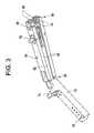
- FIG. 3is an isometric view of an attachment mechanism from FIG. 2 .
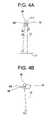
- FIG. 4 ais a geometric representation of rollers engaging a working portion having a first diameter.
- FIG. 4 bis a geometric representation of rollers engaging a working portion having a second diameter.
- FIG. 5illustrates an isometric view of an attachment mechanism formed according to an embodiment of the present invention.
- FIG. 6illustrates an isometric view of the attachment mechanism and working portion of FIG. 2 .
- FIG. 1is an isometric view of a conventional surgical instrument 10 .
- the instrument 10has a main body 14 , a handle 18 and a working portion 22 .
- the instrument 10may be a drill and the working portion 22 may be a drill bit.
- the working portion 22extends from a front portion of the instrument 10 and may be removably connected thereto, e.g., via a chuck assembly 23 .
- the working portion 22is cylindrical and rotates during operation.
- the working portion 22has a trajectory defined along a centerline 26 and has a distal tip 30 .
- any number of different working portions 22may be connected to the main body 14 during the course of a surgical procedure.
- the instrumentis a drill, it may be necessary to use a variety of drill bits during a given surgical procedure.
- the different working portionsmay have varying lengths and diameters.
- FIG. 2is an isometric view of a surgical tracking system 34 .
- the surgical tracking system 34includes the working portion 22 of the instrument 10 extending from the instrument 10 .
- An attachment mechanism 38is connected to the working portion 22 .
- the surgical tracking system 34also includes a computer 42 and a screen 46 .
- the screen 46shows images of a surgical site where the instrument 10 is to be directed.
- the attachment mechanism 38carries a tracking element 50 .
- the tracking systemis an electromagnetic based tracking system and the tracking element 50 is in the form of an electromagnetic receiver.
- the tracking element 50could take a variety of forms depending on the specific tracking system that is employed.
- the tracking systemcould be optical based, in which case the tracking element 50 could be an LED or a passive (reflective) tracking element.
- the receiver 50is connected to the computer 42 by a cord 54 .
- the receiver 50communicates with a transmitter (not shown) that is positioned proximate the surgical site in a fixed and known position relative to the surgical site.
- the transmitteris also connected to the computer 42 .
- the receiver 50 and the transmittercommunicate with each other and the computer 42 such that the computer 42 can calculate the position of the receiver 50 relative to the transmitter, and thus relative to the surgical site.
- the transmitter and/or receivercould use a wireless architecture.
- FIG. 3is an isometric view of the attachment mechanism 38 .
- the attachment mechanism 38is shaped like a clip and has two rectangular legs 58 positioned on opposite sides of a separation piece 62 .
- the legs 58are connected to the separation piece 62 at a first end 66 such that the legs 58 may rotate away from the separation piece 62 and each other at the first end 66 .
- a receiver base 70is rigidly connected to the separation piece 62 at the first end 66 .
- the receiver base 70has prongs 74 and a foot 78 on opposite ends that snapably receive the receiver 50 ( FIG. 2 ) therebetween.
- a screw 82extends through the legs 58 and the separation piece 62 proximate where the legs 58 engage the working portion 22 of the instrument 10 ( FIG. 2 ).
- the screw 82can be adjusted such that the legs 58 are evenly moved closer to the separation piece 62 , and thus each other, or such that the legs 58 are moved evenly away from the separation piece 62 , and thus away from each other.
- the separation piece 62is positioned between the legs 58 such that the legs 58 cannot be moved any closer to each other than the width of the separation piece 62 .
- Each leg 58has rollers 86 located at a second end 90 thereof.
- the rollers 86are rotatably retained on the legs 58 by pins 94 and are located on interior sides 98 of the legs 58 .
- the rollers 86 on each leg 58are a fixed distance from each other and are rotatable about the pins 94 .
- Each leg 58has a set of two or more rollers 86 .
- the set of rollers 86 on each leg 58is configured to engage the cylindrical working portion 22 ( FIG. 2 ) of the instrument 10 .
- FIG. 6illustrates an isometric view of the attachment mechanism 38 and working portion 22 of FIG. 2 .
- the attachment mechanism 38is connected to the working portion 22 by adjusting the screw 82 such that the legs 58 are rotated away from each other, or opened, until the gap between the rollers 86 on each leg 58 is large enough to receive the working portion 22 .
- the working portion 22is then positioned between the sets of rollers 86 on each leg 58 and the screw 82 is adjusted to rigidly tighten, or close, the legs 58 and rollers 86 about the working portion 22 .
- the attachment mechanism 38may be attached to the working portion 22 from the side and does not have to be slid over the distal tip 30 .
- the attachment mechanism 38can be connected to a working portion 22 having an attachment of the distal tip 30 .
- the legs 58are fixed to the working portion 22 such that the attachment mechanism 38 does not slide perpendicularly to the centerline 26 of the working portion 22 and thus the receiver base 70 is maintained at a fixed and known distance from the centerline 26 .
- the receiver base 70and thus the receiver 50 ( FIG. 2 ), is maintained a fixed and known distance D from the centerline 26 of the working portion 22 .
- the legs 58are fixed to the working portion 22 such that the attachment mechanism 38 does not slide along the centerline 26 of the working portion 22 and thus the receiver 50 is maintained at fixed distance from the distal tip 30 of the working portion 22 .
- the length of a clamp defined by legs such as those in the attachment mechanism 38changes as a function of the cosine of the angle change.
- a four inch-long clamp opened up five degreeswould create a length change, or shortening, of 0.015 inches.
- the positions of the four tangent contact pointsare adjusted such that the attachment mechanism 38 compensates for the length change.
- the geometry of the tangencies“shortens” the tool length at the same time that the cosine of the arc increases the tool length, and conversely, the geometry of the tangencies “lengthens” the tool length at the same time that the cosine of the arc decreases the tool length.
- the sets of rollers 86are oriented on each leg 58 such that the distance D does not increase or decrease as the legs 58 are closed or opened, respectively.
- the receiver 50is maintained the same known distance D from the centerline 26 of a working portion 22 , regardless of the diameter of the working portion 22 . Therefore, a surgeon can insert working portions 22 of different diameters throughout surgery without having to recalibrate the position of the receiver 50 with the centerline 26 of the new working portion 22 .
- This adaptability of the attachment mechanism 38can be better shown in the following geometric configurations.
- FIGS. 4 a and 4 bare geometric representations of the rollers 86 of one of the legs engaging a working portion 22 having a first diameter of 0.250 inches and a working portion 22 having a second diameter of 0.750 inches, respectively.
- FIG. 4 ashows the rollers 86 engaging a working portion 22 having a diameter of 0.250 inches.
- Line L 1represents a fixed plane along the receiver base 70 ( FIG. 6 ).
- Line L 2represents a plane extending along a leg 58 ( FIG. 6 ) from L 1 to a centerline 102 of the proximal roller 86 and has a value of 4.0 inches.
- Line L 3represents a plane extending along the separation piece 62 ( FIG.
- L 4is oriented to L 2 at an angle of 5.495, that is to say the centerlines 102 of the rollers 86 are oriented at an angle of 5.495 to the plane of the leg 58 .
- the rollers 86each have a diameter of 0.375 inches, the distance between L 2 and L 3 (the leg 58 and the separation piece 62 ) is 0.250 inches, the distance between the centerlines 102 of the rollers 86 is 0.400 inches, and the distance between Line L 3 and the closest tangent of the distal roller 86 is 0.033 inches.
- FIG. 4 bshows the rollers 86 engaging a working portion 22 having a diameter of 0.750 inches.
- the distance D 1 of line L 3is the same in FIG. 4 b as it is in FIG. 4 a despite FIG. 4 b showing a working portion 22 having a diameter three times the size of the working portion 22 shown in FIG. 4 a .
- the legs 58represented by line L 2
- the orientation of the rollers 86 relative to the leg 58allows for the “extension” of the leg 58 such that the length of line L 3 does not shorten.
- the rollers 86roll about a working portion 22 in order to position the rollers 86 about the working portion such that Line L 3 (the distance from the centerline 26 to a fixed point on the receiver base 70 ) remains the same length regardless of the diameter of the working portion.
- the attachment mechanism 38does not alter its distance from the working portion 22 because the rollers 86 have differing tangential contact points that engage the working portions 22 of differing diameters.
- the rollers 86have rolled clockwise about the working portion 22 such that the distal roller 86 overlaps about a far end 111 of the working portion 22 .
- the rollers 86thus accommodate for the “lengthening” of the attachment mechanism 38 caused by the legs 58 being brought close to each other.
- FIG. 4 abecause the working portion has a smaller diameter of 0.250 inches, the rollers 86 have rolled clockwise about the working portion 22 such that the distal roller 86 overlaps about a far end 111 of the working portion 22 .
- the rollers 86thus accommodate for the “lengthening” of the attachment mechanism 38 caused by the legs 58 being brought close to each other.
- the rollers 86have rolled counter-clockwise about the working portion 22 such that the distal roller 86 is positioned more along a side 106 of the working portion 22 .
- the rollersthus accommodate for the “shortening” of the attachment mechanism 38 caused by the legs 58 being separated from each other.
- the rollers 86 on the opposite legs 58roll closer to each other when the diameter of the working portion 22 is smaller and the rollers 86 on the opposite legs 58 roll further away from each other when the diameter of the working portion 22 is greater.
- the angles and lengths disclosed in FIGS. 4 a and 4 bmay be altered to accommodate attachment mechanisms 38 having different leg 58 lengths or different sized rollers 86 or to accommodate working portions 22 having different sized diameters.
- the legs 58may be any number of different lengths besides 4 inches
- the angle of the planes of the rollers 86 to the plane of the leg 58may be any number of different angles beside 5.495 degrees, etc.
- Different angles and lengths of the different components of the attachment mechanism 38 and working portion 22may be arranged to correspond with each other to accommodate for changes in the length of the attachment mechanisms 38 .
- the geometric arrangement of the rollers 86 , legs 58 , and working portions 22may result in different distances D 1 for different working portions 22 where the variation in such distances D 1 falls within an acceptable discrepancy range.
- imagesare taken of the surgical site with an imaging device such as an X-Ray, MRI, or CT scan.
- the imagesare stored on the computer 42 and can be reproduced on the screen 46 .
- the transmitteris positioned proximate the surgical site in a fixed and known position relative to the surgical site.
- the surgeonselects a working portion 22 , for example a drill bit, to be used with the instrument 10 .
- the surgeonthen connects the attachment mechanism 38 to the working portion 22 by securing the working portion 22 between the rollers 86 .
- the receiver 60 connected to the attachment mechanism 38communicates with the transmitter and the computer 42 such that the computer 42 can calculate the position of the receiver 50 relative to the transmitter and thus the surgical site. Because the receiver 50 is at a fixed and known distance D 1 ( FIG. 6 ) from the centerline 26 of the working portion 22 (regardless of the diameter of the working portion 22 ), the computer 42 can calculate the trajectory, of the working portion 22 relative to the surgical site.
- the surgeonthen calibrates the distal tip 30 of the working portion 22 by any number of ways known in the art.
- the distal tip 30may be registered at different points with other electromagnetic localizers that are in a known and fixed position relative to the transmitter or receiver 50 .
- the transmittermay include a dimple located in a fixed and known position such that the position of the receiver 50 may be known relative to the dimple as the transmitter communicates with the receiver 50 .
- the surgeonmay press the distal tip 30 of the working portion 22 into the dimple at a number of different orientations.
- the computer 42calculates the position of the distal tip 30 relative to the receiver 50 .
- the position of the distal tip 30 relative to the receiver 50may be calculated by pressing the distal tip 30 into the dimple at only one orientation.
- the computer 42can project an image of the working portion 22 on the screen 46 relative to the surgical site.
- the surgeoncan track the distal tip 30 and trajectory of the working portion 22 relative to the surgical site during surgery by viewing the screen 46 .
- the surgeoncan operate the instrument 10 while always being able to check that the working portion 22 is correctly entering the surgical site. Additionally, the surgeon can interchange working portions 22 during surgery without having to recalibrate the position of the receiver 50 relative to the trajectory of the working portion 22 .
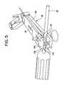
- FIG. 5illustrates an isometric view of an attachment mechanism 38 of an alternative embodiment.
- the attachment mechanism 38has sliders 110 in place of the rollers 86 ( FIG. 3 ).
- Each slider 110has two rounded pads 114 separated by a gap 118 such that the working portion 22 is received within the gap 118 and engages contact points on the pads 114 .
- the sliders 110may be made of Teflon or any other material that will allow the slider 110 to slide along the working portion 22 .
- Each slider 110is aligned along a first plane 130 and each leg 58 is aligned along a second plane 134 .
- the first plane 130is oriented at an angle to the second plane 134 .
- the pads 118have differing tangential contact points that engage the working portions 22 of differing diameters such that the sliders 110 operate similarly to the rollers 86 in sliding about the working portion 22 to accommodate for changes in length of the attachment mechanism 38 .
- the attachment mechanismmay be used with any number of other medical instruments besides a drill.
- the attachment mechanismmay be used with non-medical instruments that are used as a part of a tracking system.
- the attachment mechanismmay be used to connect any device a fixed distance from the centerline of any instrument having a cylindrical working portion.
- the attachment mechanismmay carry a transmitter instead of a receiver.
- the attachment mechanismmay be used with different tracking systems besides electromagnetic systems.
- the attachment mechanismmay be used with an optical system that utilizes LED's, optical reflectors, and cameras.
- the attachment mechanismmay have other engagement pieces besides rollers or sliders that engage working portions at different contact points to accommodate the opening and closing of the attachment mechanism.
- the localize elementmay be mounted to one or both of the legs instead of being connected by a base and the separation piece.
- the rollers/sliders attachment meansthat is oriented to the plane of the leg at an angle allows the attachment mechanism to be connected to cylindrical, rotating shafts of differing diameters without altering the distance or orientation of the receiver to the centerline of the shaft.
- the attachment mechanismprovides a universal means for attaching a localizing device to an instrument and calibrating the localizing device with the trajectory and distal tip of the instrument. Therefore, localizing devices do not have to be integrated into every new instrument that is developed, rather the localizing device may be calibrated with any cylindrical instrument working portion regardless of size or make. Additionally, a surgeon does not have to recalibrate the receiver to find the trajectory of the working portion for each new working portion that is attached to the instrument.
- the instrumentitself does not need to have any localizing devices attached thereto nor does the surgeon have to insert the instrument into a cumbersome block each time the surgeon wishes to use a new working portion with the instrument.
- the “clothes-pin” design of the attachment mechanismallows the attachment mechanism to clamp onto the side of an instrument instead of being slid over the distal tip.
- the attachment mechanismmay be connected to instruments having large attachments at the distal end that the attachment mechanism could not be slid about.
Landscapes
- Health & Medical Sciences (AREA)
- Surgery (AREA)
- Life Sciences & Earth Sciences (AREA)
- Engineering & Computer Science (AREA)
- Biomedical Technology (AREA)
- Public Health (AREA)
- Veterinary Medicine (AREA)
- Nuclear Medicine, Radiotherapy & Molecular Imaging (AREA)
- General Health & Medical Sciences (AREA)
- Heart & Thoracic Surgery (AREA)
- Medical Informatics (AREA)
- Molecular Biology (AREA)
- Animal Behavior & Ethology (AREA)
- Oral & Maxillofacial Surgery (AREA)
- Pathology (AREA)
- Dentistry (AREA)
- Orthopedic Medicine & Surgery (AREA)
- Robotics (AREA)
- Surgical Instruments (AREA)
Abstract
Description
Claims (20)
Priority Applications (3)
| Application Number | Priority Date | Filing Date | Title |
|---|---|---|---|
| US10/699,960US7153297B2 (en) | 2003-11-03 | 2003-11-03 | Universal attachment mechanism for attaching a tracking device to an instrument |
| FR0411389AFR2861830B1 (en) | 2003-11-03 | 2004-10-26 | UNIVERSAL MOUNTING MECHANISM FOR ATTACHING AN INSTRUMENT FOLLOWING DEVICE |
| DE102004053684ADE102004053684A1 (en) | 2003-11-03 | 2004-11-03 | Universal fastening device for attaching a tracking device to an instrument |
Applications Claiming Priority (1)
| Application Number | Priority Date | Filing Date | Title |
|---|---|---|---|
| US10/699,960US7153297B2 (en) | 2003-11-03 | 2003-11-03 | Universal attachment mechanism for attaching a tracking device to an instrument |
Publications (2)
| Publication Number | Publication Date |
|---|---|
| US20050096536A1 US20050096536A1 (en) | 2005-05-05 |
| US7153297B2true US7153297B2 (en) | 2006-12-26 |
Family
ID=34435515
Family Applications (1)
| Application Number | Title | Priority Date | Filing Date |
|---|---|---|---|
| US10/699,960Expired - LifetimeUS7153297B2 (en) | 2003-11-03 | 2003-11-03 | Universal attachment mechanism for attaching a tracking device to an instrument |
Country Status (3)
| Country | Link |
|---|---|
| US (1) | US7153297B2 (en) |
| DE (1) | DE102004053684A1 (en) |
| FR (1) | FR2861830B1 (en) |
Cited By (22)
| Publication number | Priority date | Publication date | Assignee | Title |
|---|---|---|---|---|
| US7398116B2 (en) | 2003-08-11 | 2008-07-08 | Veran Medical Technologies, Inc. | Methods, apparatuses, and systems useful in conducting image guided interventions |
| US20080204000A1 (en)* | 2007-02-26 | 2008-08-28 | General Electric Company | Universal instrument calibration system and method of use |
| US20090096443A1 (en)* | 2007-10-11 | 2009-04-16 | General Electric Company | Coil arrangement for an electromagnetic tracking system |
| US7920909B2 (en) | 2005-09-13 | 2011-04-05 | Veran Medical Technologies, Inc. | Apparatus and method for automatic image guided accuracy verification |
| US8150495B2 (en) | 2003-08-11 | 2012-04-03 | Veran Medical Technologies, Inc. | Bodily sealants and methods and apparatus for image-guided delivery of same |
| US8696549B2 (en) | 2010-08-20 | 2014-04-15 | Veran Medical Technologies, Inc. | Apparatus and method for four dimensional soft tissue navigation in endoscopic applications |
| US8781186B2 (en) | 2010-05-04 | 2014-07-15 | Pathfinder Therapeutics, Inc. | System and method for abdominal surface matching using pseudo-features |
| US9138165B2 (en) | 2012-02-22 | 2015-09-22 | Veran Medical Technologies, Inc. | Systems, methods and devices for forming respiratory-gated point cloud for four dimensional soft tissue navigation |
| US9993273B2 (en) | 2013-01-16 | 2018-06-12 | Mako Surgical Corp. | Bone plate and tracking device using a bone plate for attaching to a patient's anatomy |
| US10531925B2 (en) | 2013-01-16 | 2020-01-14 | Stryker Corporation | Navigation systems and methods for indicating and reducing line-of-sight errors |
| US10537395B2 (en) | 2016-05-26 | 2020-01-21 | MAKO Surgical Group | Navigation tracker with kinematic connector assembly |
| US10617324B2 (en) | 2014-04-23 | 2020-04-14 | Veran Medical Technologies, Inc | Apparatuses and methods for endobronchial navigation to and confirmation of the location of a target tissue and percutaneous interception of the target tissue |
| US10624701B2 (en) | 2014-04-23 | 2020-04-21 | Veran Medical Technologies, Inc. | Apparatuses and methods for registering a real-time image feed from an imaging device to a steerable catheter |
| US20200205919A1 (en)* | 2019-01-01 | 2020-07-02 | Transenterix Surgical, Inc. | Dynamic control of surgical instruments in a surgical system using repulsion/attraction modes |
| US10709508B2 (en) | 2016-07-28 | 2020-07-14 | Medtronics Ps Medical, Inc. | Tracked powered drill assembly |
| US10731687B2 (en) | 2017-11-22 | 2020-08-04 | Medos International Sarl | Instrument coupling interfaces and related methods |
| US11304630B2 (en) | 2005-09-13 | 2022-04-19 | Veran Medical Technologies, Inc. | Apparatus and method for image guided accuracy verification |
| US11644053B2 (en) | 2019-11-26 | 2023-05-09 | Medos International Sarl | Instrument coupling interfaces and related methods |
| US12059804B2 (en) | 2019-05-22 | 2024-08-13 | Mako Surgical Corp. | Bidirectional kinematic mount |
| US12357397B2 (en) | 2022-05-09 | 2025-07-15 | Proprio, Inc. | Methods and systems for calibrating instruments within an imaging system, such as a surgical imaging system |
| US12383350B2 (en) | 2021-09-08 | 2025-08-12 | Proprio, Inc. | Constellations for tracking instruments, such as surgical instruments, and associated systems and methods |
| USD1091816S1 (en) | 2023-04-19 | 2025-09-02 | Stryker European Operations Limited | Surgical instrument tracker |
Families Citing this family (5)
| Publication number | Priority date | Publication date | Assignee | Title |
|---|---|---|---|---|
| US7926776B2 (en)* | 2008-04-29 | 2011-04-19 | Civco Medical Instruments Co., Inc. | Bracket for mounting at least one position detecting sensor on an ultrasonic probe |
| US8611985B2 (en) | 2009-01-29 | 2013-12-17 | Imactis | Method and device for navigation of a surgical tool |
| US9706868B2 (en) | 2011-02-15 | 2017-07-18 | Brainlab Ag | Drape-clamping reference array connector |
| EP2996603B1 (en) | 2013-03-20 | 2019-01-02 | Brainlab AG | Adaptor for receiving a navigated structure which is at least a part of a medical object and method of registering a navigated structure using the adaptor |
| US20220240909A1 (en)* | 2021-01-29 | 2022-08-04 | Proprio, Inc. | Clamp device for use with a tool, such as a rotatable medical tool |
Citations (9)
| Publication number | Priority date | Publication date | Assignee | Title |
|---|---|---|---|---|
| DE83507C (en) | ||||
| US4190224A (en) | 1977-04-25 | 1980-02-26 | Leblanc Edgar J | Intravenous pole holder |
| US5099577A (en)* | 1991-04-17 | 1992-03-31 | Heinz Hutt | Releasable knife axle for tube cutter |
| US5380338A (en)* | 1992-09-03 | 1995-01-10 | Minnesota Scientific, Inc. | Laparoscope holder with rotatable gripping pads |
| DE4438633A1 (en) | 1994-10-28 | 1996-05-02 | Hunger Maschfab Ludwig | Clamp with two clamping arms |
| US5987960A (en) | 1997-09-26 | 1999-11-23 | Picker International, Inc. | Tool calibrator |
| DE29912742U1 (en) | 1999-07-21 | 1999-11-25 | Haug, Helmut, 72458 Albstadt | Device holder |
| US6358199B1 (en)* | 1998-05-06 | 2002-03-19 | Stm Medizintechnik Starnberg Gmbh | Drive means for flexible eversion tube system |
| WO2002061371A1 (en) | 2001-01-30 | 2002-08-08 | Z-Kat, Inc. | Tool calibrator and tracker system |
- 2003
- 2003-11-03USUS10/699,960patent/US7153297B2/ennot_activeExpired - Lifetime
- 2004
- 2004-10-26FRFR0411389Apatent/FR2861830B1/ennot_activeExpired - Fee Related
- 2004-11-03DEDE102004053684Apatent/DE102004053684A1/ennot_activeWithdrawn
Patent Citations (9)
| Publication number | Priority date | Publication date | Assignee | Title |
|---|---|---|---|---|
| DE83507C (en) | ||||
| US4190224A (en) | 1977-04-25 | 1980-02-26 | Leblanc Edgar J | Intravenous pole holder |
| US5099577A (en)* | 1991-04-17 | 1992-03-31 | Heinz Hutt | Releasable knife axle for tube cutter |
| US5380338A (en)* | 1992-09-03 | 1995-01-10 | Minnesota Scientific, Inc. | Laparoscope holder with rotatable gripping pads |
| DE4438633A1 (en) | 1994-10-28 | 1996-05-02 | Hunger Maschfab Ludwig | Clamp with two clamping arms |
| US5987960A (en) | 1997-09-26 | 1999-11-23 | Picker International, Inc. | Tool calibrator |
| US6358199B1 (en)* | 1998-05-06 | 2002-03-19 | Stm Medizintechnik Starnberg Gmbh | Drive means for flexible eversion tube system |
| DE29912742U1 (en) | 1999-07-21 | 1999-11-25 | Haug, Helmut, 72458 Albstadt | Device holder |
| WO2002061371A1 (en) | 2001-01-30 | 2002-08-08 | Z-Kat, Inc. | Tool calibrator and tracker system |
Non-Patent Citations (1)
| Title |
|---|
| French search report for App No.FR 0411389 dated Feb. 14, 2006. |
Cited By (58)
| Publication number | Priority date | Publication date | Assignee | Title |
|---|---|---|---|---|
| US8483801B2 (en) | 2003-08-11 | 2013-07-09 | Veran Medical Technologies, Inc. | Methods, apparatuses, and systems useful in conducting image guided interventions |
| US11154283B2 (en) | 2003-08-11 | 2021-10-26 | Veran Medical Technologies, Inc. | Bodily sealants and methods and apparatus for image-guided delivery of same |
| US11426134B2 (en) | 2003-08-11 | 2022-08-30 | Veran Medical Technologies, Inc. | Methods, apparatuses and systems useful in conducting image guided interventions |
| US7853307B2 (en) | 2003-08-11 | 2010-12-14 | Veran Medical Technologies, Inc. | Methods, apparatuses, and systems useful in conducting image guided interventions |
| US10470725B2 (en) | 2003-08-11 | 2019-11-12 | Veran Medical Technologies, Inc. | Method, apparatuses, and systems useful in conducting image guided interventions |
| US7398116B2 (en) | 2003-08-11 | 2008-07-08 | Veran Medical Technologies, Inc. | Methods, apparatuses, and systems useful in conducting image guided interventions |
| US8150495B2 (en) | 2003-08-11 | 2012-04-03 | Veran Medical Technologies, Inc. | Bodily sealants and methods and apparatus for image-guided delivery of same |
| US7920909B2 (en) | 2005-09-13 | 2011-04-05 | Veran Medical Technologies, Inc. | Apparatus and method for automatic image guided accuracy verification |
| US9218663B2 (en) | 2005-09-13 | 2015-12-22 | Veran Medical Technologies, Inc. | Apparatus and method for automatic image guided accuracy verification |
| US9218664B2 (en) | 2005-09-13 | 2015-12-22 | Veran Medical Technologies, Inc. | Apparatus and method for image guided accuracy verification |
| US11304629B2 (en) | 2005-09-13 | 2022-04-19 | Veran Medical Technologies, Inc. | Apparatus and method for image guided accuracy verification |
| US11304630B2 (en) | 2005-09-13 | 2022-04-19 | Veran Medical Technologies, Inc. | Apparatus and method for image guided accuracy verification |
| US10617332B2 (en) | 2005-09-13 | 2020-04-14 | Veran Medical Technologies, Inc. | Apparatus and method for image guided accuracy verification |
| US8067726B2 (en)* | 2007-02-26 | 2011-11-29 | General Electric Company | Universal instrument calibration system and method of use |
| US20080204000A1 (en)* | 2007-02-26 | 2008-08-28 | General Electric Company | Universal instrument calibration system and method of use |
| US8391952B2 (en) | 2007-10-11 | 2013-03-05 | General Electric Company | Coil arrangement for an electromagnetic tracking system |
| US20090096443A1 (en)* | 2007-10-11 | 2009-04-16 | General Electric Company | Coil arrangement for an electromagnetic tracking system |
| US8781186B2 (en) | 2010-05-04 | 2014-07-15 | Pathfinder Therapeutics, Inc. | System and method for abdominal surface matching using pseudo-features |
| US10898057B2 (en) | 2010-08-20 | 2021-01-26 | Veran Medical Technologies, Inc. | Apparatus and method for airway registration and navigation |
| US10165928B2 (en) | 2010-08-20 | 2019-01-01 | Mark Hunter | Systems, instruments, and methods for four dimensional soft tissue navigation |
| US11690527B2 (en) | 2010-08-20 | 2023-07-04 | Veran Medical Technologies, Inc. | Apparatus and method for four dimensional soft tissue navigation in endoscopic applications |
| US10264947B2 (en) | 2010-08-20 | 2019-04-23 | Veran Medical Technologies, Inc. | Apparatus and method for airway registration and navigation |
| US8696549B2 (en) | 2010-08-20 | 2014-04-15 | Veran Medical Technologies, Inc. | Apparatus and method for four dimensional soft tissue navigation in endoscopic applications |
| US11109740B2 (en) | 2010-08-20 | 2021-09-07 | Veran Medical Technologies, Inc. | Apparatus and method for four dimensional soft tissue navigation in endoscopic applications |
| US9138165B2 (en) | 2012-02-22 | 2015-09-22 | Veran Medical Technologies, Inc. | Systems, methods and devices for forming respiratory-gated point cloud for four dimensional soft tissue navigation |
| US11551359B2 (en) | 2012-02-22 | 2023-01-10 | Veran Medical Technologies, Inc | Systems, methods and devices for forming respiratory-gated point cloud for four dimensional soft tissue navigation |
| US11403753B2 (en) | 2012-02-22 | 2022-08-02 | Veran Medical Technologies, Inc. | Surgical catheter having side exiting medical instrument and related systems and methods for four dimensional soft tissue navigation |
| US10249036B2 (en) | 2012-02-22 | 2019-04-02 | Veran Medical Technologies, Inc. | Surgical catheter having side exiting medical instrument and related systems and methods for four dimensional soft tissue navigation |
| US11830198B2 (en) | 2012-02-22 | 2023-11-28 | Veran Medical Technologies, Inc. | Systems, methods and devices for forming respiratory-gated point cloud for four dimensional soft tissue navigation |
| US10460437B2 (en) | 2012-02-22 | 2019-10-29 | Veran Medical Technologies, Inc. | Method for placing a localization element in an organ of a patient for four dimensional soft tissue navigation |
| US9972082B2 (en) | 2012-02-22 | 2018-05-15 | Veran Medical Technologies, Inc. | Steerable surgical catheter having biopsy devices and related systems and methods for four dimensional soft tissue navigation |
| US10140704B2 (en) | 2012-02-22 | 2018-11-27 | Veran Medical Technologies, Inc. | Systems, methods and devices for forming respiratory-gated point cloud for four dimensional soft tissue navigation |
| US10977789B2 (en) | 2012-02-22 | 2021-04-13 | Veran Medical Technologies, Inc. | Systems, methods and devices for forming respiratory-gated point cloud for four dimensional soft tissue navigation |
| US11369438B2 (en) | 2013-01-16 | 2022-06-28 | Stryker Corporation | Navigation systems and methods for indicating and reducing line-of-sight errors |
| US10932837B2 (en) | 2013-01-16 | 2021-03-02 | Mako Surgical Corp. | Tracking device using a bone plate for attaching to a patient's anatomy |
| US9993273B2 (en) | 2013-01-16 | 2018-06-12 | Mako Surgical Corp. | Bone plate and tracking device using a bone plate for attaching to a patient's anatomy |
| US11622800B2 (en) | 2013-01-16 | 2023-04-11 | Mako Surgical Corp. | Bone plate for attaching to an anatomic structure |
| US12102365B2 (en) | 2013-01-16 | 2024-10-01 | Mako Surgical Corp. | Bone plate for attaching to an anatomic structure |
| US12290321B2 (en) | 2013-01-16 | 2025-05-06 | Stryker Corporation | Navigation systems and methods for indicating and reducing line-of-sight errors |
| US10531925B2 (en) | 2013-01-16 | 2020-01-14 | Stryker Corporation | Navigation systems and methods for indicating and reducing line-of-sight errors |
| US10624701B2 (en) | 2014-04-23 | 2020-04-21 | Veran Medical Technologies, Inc. | Apparatuses and methods for registering a real-time image feed from an imaging device to a steerable catheter |
| US10617324B2 (en) | 2014-04-23 | 2020-04-14 | Veran Medical Technologies, Inc | Apparatuses and methods for endobronchial navigation to and confirmation of the location of a target tissue and percutaneous interception of the target tissue |
| US11553968B2 (en) | 2014-04-23 | 2023-01-17 | Veran Medical Technologies, Inc. | Apparatuses and methods for registering a real-time image feed from an imaging device to a steerable catheter |
| US11559358B2 (en) | 2016-05-26 | 2023-01-24 | Mako Surgical Corp. | Surgical assembly with kinematic connector |
| US10537395B2 (en) | 2016-05-26 | 2020-01-21 | MAKO Surgical Group | Navigation tracker with kinematic connector assembly |
| US11819289B2 (en) | 2016-07-28 | 2023-11-21 | Medtronic Ps Medical, Inc. | Tracked powered drill assembly |
| US10709508B2 (en) | 2016-07-28 | 2020-07-14 | Medtronics Ps Medical, Inc. | Tracked powered drill assembly |
| US10731687B2 (en) | 2017-11-22 | 2020-08-04 | Medos International Sarl | Instrument coupling interfaces and related methods |
| US11957425B2 (en)* | 2019-01-01 | 2024-04-16 | Asensus Surgical Us, Inc. | Dynamic control of surgical instruments in a surgical robotic system using repulsion/attraction modes |
| US20230225814A1 (en)* | 2019-01-01 | 2023-07-20 | Asensus Surgical Us, Inc. | Dynamic control of surgical instruments in a surgical robotic system using repulsion/attraction modes |
| US11607283B2 (en)* | 2019-01-01 | 2023-03-21 | Asensus Surgical Us, Inc. | Dynamic control of surgical instruments in a surgical system using repulsion/attraction modes |
| US20200205919A1 (en)* | 2019-01-01 | 2020-07-02 | Transenterix Surgical, Inc. | Dynamic control of surgical instruments in a surgical system using repulsion/attraction modes |
| US12059804B2 (en) | 2019-05-22 | 2024-08-13 | Mako Surgical Corp. | Bidirectional kinematic mount |
| US12060908B2 (en) | 2019-11-26 | 2024-08-13 | Medos International Sarl | Instrument coupling interfaces and related methods |
| US11644053B2 (en) | 2019-11-26 | 2023-05-09 | Medos International Sarl | Instrument coupling interfaces and related methods |
| US12383350B2 (en) | 2021-09-08 | 2025-08-12 | Proprio, Inc. | Constellations for tracking instruments, such as surgical instruments, and associated systems and methods |
| US12357397B2 (en) | 2022-05-09 | 2025-07-15 | Proprio, Inc. | Methods and systems for calibrating instruments within an imaging system, such as a surgical imaging system |
| USD1091816S1 (en) | 2023-04-19 | 2025-09-02 | Stryker European Operations Limited | Surgical instrument tracker |
Also Published As
| Publication number | Publication date |
|---|---|
| FR2861830B1 (en) | 2007-02-09 |
| US20050096536A1 (en) | 2005-05-05 |
| DE102004053684A1 (en) | 2005-06-02 |
| FR2861830A1 (en) | 2005-05-06 |
Similar Documents
| Publication | Publication Date | Title |
|---|---|---|
| US7153297B2 (en) | Universal attachment mechanism for attaching a tracking device to an instrument | |
| EP1364183B1 (en) | Tool calibrator and tracker system | |
| JP7187198B2 (en) | System for Surgical Tool Insertion Using Multi-Axis Force and Moment Feedback | |
| JP7112224B2 (en) | Robotic Surgical Automation Using Tracking Markers | |
| US11547497B2 (en) | Attachments for tracking handheld implements | |
| US7873400B2 (en) | Adapter for surgical navigation trackers | |
| US6081336A (en) | Microscope calibrator | |
| CN111095425B (en) | Intraoperative alignment assessment system and method | |
| US7771436B2 (en) | Surgical navigation tracker, system and method | |
| US7846103B2 (en) | Probe guide for use with medical imaging systems | |
| US6556857B1 (en) | Rotation locking driver for image guided instruments | |
| AU2003270992B2 (en) | Surgical instrument and positioning method | |
| US5987960A (en) | Tool calibrator | |
| TWI435705B (en) | Surgical position device and image guided navigation system using the same | |
| US20040077940A1 (en) | Instrument guide for use with a tracking system | |
| CN109758232B (en) | Surgical robotic system and retractor for same | |
| US20050215888A1 (en) | Universal support arm and tracking array | |
| US20020193800A1 (en) | Surgical drill for use with a computer assisted surgery system | |
| US20020010479A1 (en) | Medical device introducer | |
| US8535321B2 (en) | Surgical assembly having a guide block | |
| US20040073228A1 (en) | Adjustable instruments for use with an electromagnetic localizer | |
| CN112932668A (en) | Surgical robotic system for performing surgery on anatomical features of a patient | |
| JP7366191B2 (en) | System for Surgical Tool Insertion Using Multi-Axis Force and Moment Feedback | |
| Maier-Hein et al. | Comparative assessment of optical tracking systems for soft tissue navigation with fiducial needles |
Legal Events
| Date | Code | Title | Description |
|---|---|---|---|
| AS | Assignment | Owner name:GE MEDICAL SYSTEMS GLOBAL TECHNOLOGY CO., LLC, WIS Free format text:ASSIGNMENT OF ASSIGNORS INTEREST;ASSIGNOR:PETERSON, THOMAS H.;REEL/FRAME:014671/0903 Effective date:20031029 | |
| FEPP | Fee payment procedure | Free format text:PAYOR NUMBER ASSIGNED (ORIGINAL EVENT CODE: ASPN); ENTITY STATUS OF PATENT OWNER: LARGE ENTITY | |
| STCF | Information on status: patent grant | Free format text:PATENTED CASE | |
| FPAY | Fee payment | Year of fee payment:4 | |
| FPAY | Fee payment | Year of fee payment:8 | |
| AS | Assignment | Owner name:STRYKER EUROPEAN HOLDINGS I, LLC, MICHIGAN Free format text:ASSIGNMENT OF ASSIGNORS INTEREST;ASSIGNOR:GENERAL ELECTRIC COMPANY;REEL/FRAME:046020/0621 Effective date:20171206 | |
| MAFP | Maintenance fee payment | Free format text:PAYMENT OF MAINTENANCE FEE, 12TH YEAR, LARGE ENTITY (ORIGINAL EVENT CODE: M1553) Year of fee payment:12 | |
| AS | Assignment | Owner name:STRYKER EUROPEAN HOLDINGS III, LLC, DELAWARE Free format text:NUNC PRO TUNC ASSIGNMENT;ASSIGNOR:STRYKER EUROPEAN HOLDINGS I, LLC;REEL/FRAME:056969/0771 Effective date:20210219 Owner name:STRYKER EUROPEAN OPERATIONS HOLDINGS LLC, MICHIGAN Free format text:CHANGE OF NAME;ASSIGNOR:STRYKER EUROPEAN HOLDINGS III, LLC;REEL/FRAME:056969/0893 Effective date:20190226 |