US7153281B2 - Apparatus and method for measuring instability of a motion segment unit of a spine - Google Patents
Apparatus and method for measuring instability of a motion segment unit of a spineDownload PDFInfo
- Publication number
- US7153281B2 US7153281B2US10/697,852US69785203AUS7153281B2US 7153281 B2US7153281 B2US 7153281B2US 69785203 AUS69785203 AUS 69785203AUS 7153281 B2US7153281 B2US 7153281B2
- Authority
- US
- United States
- Prior art keywords
- motion segment
- segment unit
- assembly
- arm
- collar assembly
- Prior art date
- Legal status (The legal status is an assumption and is not a legal conclusion. Google has not performed a legal analysis and makes no representation as to the accuracy of the status listed.)
- Expired - Lifetime, expires
Links
Images


Classifications
- A—HUMAN NECESSITIES
- A61—MEDICAL OR VETERINARY SCIENCE; HYGIENE
- A61B—DIAGNOSIS; SURGERY; IDENTIFICATION
- A61B17/00—Surgical instruments, devices or methods
- A61B17/02—Surgical instruments, devices or methods for holding wounds open, e.g. retractors; Tractors
- A61B17/025—Joint distractors
- A—HUMAN NECESSITIES
- A61—MEDICAL OR VETERINARY SCIENCE; HYGIENE
- A61B—DIAGNOSIS; SURGERY; IDENTIFICATION
- A61B5/00—Measuring for diagnostic purposes; Identification of persons
- A61B5/22—Ergometry; Measuring muscular strength or the force of a muscular blow
- A61B5/224—Measuring muscular strength
- A—HUMAN NECESSITIES
- A61—MEDICAL OR VETERINARY SCIENCE; HYGIENE
- A61B—DIAGNOSIS; SURGERY; IDENTIFICATION
- A61B5/00—Measuring for diagnostic purposes; Identification of persons
- A61B5/45—For evaluating or diagnosing the musculoskeletal system or teeth
- A61B5/4538—Evaluating a particular part of the muscoloskeletal system or a particular medical condition
- A61B5/4561—Evaluating static posture, e.g. undesirable back curvature
- A—HUMAN NECESSITIES
- A61—MEDICAL OR VETERINARY SCIENCE; HYGIENE
- A61B—DIAGNOSIS; SURGERY; IDENTIFICATION
- A61B17/00—Surgical instruments, devices or methods
- A61B17/02—Surgical instruments, devices or methods for holding wounds open, e.g. retractors; Tractors
- A61B17/025—Joint distractors
- A61B2017/0256—Joint distractors for the spine
- A—HUMAN NECESSITIES
- A61—MEDICAL OR VETERINARY SCIENCE; HYGIENE
- A61B—DIAGNOSIS; SURGERY; IDENTIFICATION
- A61B17/00—Surgical instruments, devices or methods
- A61B17/02—Surgical instruments, devices or methods for holding wounds open, e.g. retractors; Tractors
- A61B17/025—Joint distractors
- A61B2017/0268—Joint distractors for the knee
- A—HUMAN NECESSITIES
- A61—MEDICAL OR VETERINARY SCIENCE; HYGIENE
- A61B—DIAGNOSIS; SURGERY; IDENTIFICATION
- A61B90/00—Instruments, implements or accessories specially adapted for surgery or diagnosis and not covered by any of the groups A61B1/00 - A61B50/00, e.g. for luxation treatment or for protecting wound edges
- A61B90/06—Measuring instruments not otherwise provided for
- A61B2090/061—Measuring instruments not otherwise provided for for measuring dimensions, e.g. length
- A—HUMAN NECESSITIES
- A61—MEDICAL OR VETERINARY SCIENCE; HYGIENE
- A61B—DIAGNOSIS; SURGERY; IDENTIFICATION
- A61B90/00—Instruments, implements or accessories specially adapted for surgery or diagnosis and not covered by any of the groups A61B1/00 - A61B50/00, e.g. for luxation treatment or for protecting wound edges
- A61B90/06—Measuring instruments not otherwise provided for
- A61B2090/064—Measuring instruments not otherwise provided for for measuring force, pressure or mechanical tension
- A—HUMAN NECESSITIES
- A61—MEDICAL OR VETERINARY SCIENCE; HYGIENE
- A61B—DIAGNOSIS; SURGERY; IDENTIFICATION
- A61B5/00—Measuring for diagnostic purposes; Identification of persons
- A61B5/45—For evaluating or diagnosing the musculoskeletal system or teeth
- A61B5/4504—Bones
Definitions
- the present inventionis generally directed to an apparatus and method for measuring instability of a motion segment unit of a spine in which at least two force applying members are attached in spaced apart locations to the motion segment unit and a force applied thereto to assist a surgeon in selecting a suitable course of treatment to correct or improve the instability of the motion segment unit.
- back painis one of the most frequently occurring and expensive disabling ailments, especially for patients in the 30–60 year age bracket. Although back pain syndrome is a very common occurrence, its diagnosis to this day is very difficult.
- the vertebral columnis a biomechanical structure composed primarily of ligaments, muscles, vertebrae and intervertebrae discs.
- the biomechanical functions of the spineinclude (1) support of the body (trunk and appendages), which involves the transfer of the weight and the bending moments of the head, trunk and arms to the pelvis and legs, (2) complex physiologic motion between these body parts, and (3) protection of the spinal cord and nerve roots.
- the major regions of the spineare the cervical, thoracic, lumbar and sacral.
- the vertebraeincrease in size and mass from the cervical to the lumbar regions.
- the increase in size of the vertebraeis directly related to an increased capacity for supporting larger loads.
- the lumbar regionis therefore the major load bearer of the spine.
- this increase in load bearing capacityis paralleled by a decrease in flexibility. Because the lumbar regions bears heavier loads than other regions of the spine, the lumbar trunk (low back structure) is more, but not exclusively, susceptible to strain and hence back pain.
- the spineis comprised of different levels known as motion segment units.
- the lumbar spinefor example, is comprised of five motion segment units.
- the motion segment unitis the smallest component of the spine that exhibits kinematic behavior similar to that of the whole spine.
- the motion segment unitis capable of flexion, extension, lateral bending, torsion and translation.
- the components of each motion segment unitinclude two adjacent vertebrae and their apophyseal joints, the intervertebral disc and the connecting ligamentous tissue.
- Segmental instabilityis defined as “the loss of ability of the spine under physiologic loads to maintain relationships between vertebrae in such a way that there is neither damage nor subsequent irritation to the spinal cord or nerve roots, and, in addition, there is no development of incapacitating deformity or pain due to structural changes”. Instability is therefore an abnormal response to applied loads characterized by motion in the motion segment unit beyond normal constraints. Excess motion can be abnormal in quality (i.e., abnormal coupling patterns) or in quantity (abnormal increased motion) or both. Excess motion may well result in damage to the nerve roots, the spinal cord, and other spinal structures.
- the underlying causes of the structural changes in the motion segment unit leading to instabilityare trauma, degeneration, aging, disease (tumor, infection, etc.), surgery, or a combination thereof. It is known that a mechanically unstable motion segment unit can originate due to loss of biomechanical function of the spine joint ligaments and degeneration of the intervertebral disc and nucleus pulposus. A degenerate nucleus polposus causes disc space narrowing, loss of viscoelastic properties and the subsequent transfer of compressive loads to the annulus fibrosus. The altered anatomic dimensions and subsequent abnormal response to loading can cause loss of pretension in the ligamenum flavum, and longitudinal ligaments, degeneration of the facet capsules (and possible subluxation) with a consequence of secondary degenerative osteoarthritis of the joints.
- the apparatus disclosed in this referenceprovides a vertebrae distractor including a device for applying a constant rate of increasing force against adjacent vertebrae of a motion segment unit to thereby distract or separate the vertebrae. Means for detecting and recording the changes in the resistance to distraction are also provided.
- the device disclosed in the '761 Patentwhile providing useful objective criteria regarding the relative stiffness of a motion segment unit of the spine, nonetheless, requires the removal of spinal tissue in order to place the distractor legs in a suitable position for operating the device as shown in FIG. 2 of the reference.
- an apparatus and method for measuring instability of a motion segment unit of the spinein which significant damage and/or removal of spinal tissue is reduced or eliminated during the process of making measurements of the relative stiffness of the spine.
- the apparatus and methodmay be effectively employed in a comprehensive system of associating a measured characteristic of the motion segment unit (e.g. stiffness) which an appropriate spinal assist device (e.g. a spinal implant device) to reduce or eliminate the instability of the affected motion segment unit.
- an apparatus and method for measuring instability of a motion segment unit of a spinecomprising:
- the controllable force or load generated by the motor means and applied through the distractor arm assemblymay be a force sufficient to provide a constant rate of distraction on the motion segment unit or may be a constant rate of force resulting in a particular displacement profile of the motion segment unit.
- the resulting force or displacement readingscan be associated with a characteristic of the motion segment unit (e.g. stiffness) facilitating the adaptation by the surgeon of a suitable course of treatment.
- an apparatus and method for measuring instability of a motion segment unit of a spinecomprising:
- the apparatusis adapted to engage a spine imbedded attachment device within a preselected portion of the motion segment unit and through the attachment device the constant rate of force is exerted against respective portions of the motion segment unit.
- a detection meansconnected to the distractor arm assembly for measuring the resistance of the pair of arms to said distraction which is related to the resistance of the adjacent vertebrae of the motion segment unit to said distraction, at a plurality of force exerting positions, said detection means generating an output signal corresponding to said resistance.
- translation meansadapted to receive the output signal for the detection means and for translating the output signal into interpretable data such as a stiffness value.
- FIG. 1is a side view of a first embodiment of the apparatus of the present invention including a distractor arm assembly including two distractor arms for placement between adjacent vertebrae of a motion segment unit and a motor assembly for operating the distractor arm assembly contained with a housing;
- FIG. 2is a perspective view of a further embodiment of a distractor arm assembly with two distractor arms in accordance with the present invention
- FIG. 3is a perspective view of a portion of a distractor arm employing reusable or disposable pins for contacting the motion segment unit;
- FIG. 4is a cross-sectional view of the embodiment of the apparatus of the present invention shown in FIG. 1 ;
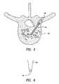
- FIG. 5is a cross-sectional view of a lumbar vertebrae showing a pedicle screw inserted therein wherein the pedicle screw is engageable by the distractor arm assembly of the present invention
- FIG. 6is a schematic view of a portion of an arm of a distractor assembly adapted to engage a pedicle screw of the type shown in FIG. 5 ;
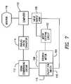
- FIG. 7is a schematic view of a system for evaluating instability of the motion segment unit using the apparatus of the present invention.
- FIG. 8is a side elevational view of a further embodiment of the apparatus of the present invention employing a distractor arm assembly including a dual leg assembly;
- FIG. 9is a perspective view of a further embodiment of a distractor arm assembly having a dual leg assembly in accordance with the present invention.
- FIG. 10is a perspective view of a further embodiment of the distractor arm assembly having a dual leg assembly in accordance with the present invention.
- FIG. 11is a perspective view of a still further embodiment of the distractor arm assembly having a dual leg assembly of the present invention.
- an apparatus 2 of the present inventionwhich includes a stepper motor assembly 4 (See FIG. 4 ) which is capable of applying force preferably at a constant rate to a distractor arm assembly 8 as hereinafter described.
- a stepper motor assembly 4is described in U.S. Pat. No. 4,899,761 incorporated herein by reference.
- the stepper motor assembly 4is contained within a housing 6 .
- the apparatusalso includes a distractor arm assembly 8 which, as described in detail hereinafter, is able to apply a constant force to spaced apart locations of a motion segment unit to separate and/or distract, and/or torque the same and thereby to enable the determination of reliable data on a characteristic (e.g. relative stiffness) of the motion segment unit.
- a distractor arm assembly 8which, as described in detail hereinafter, is able to apply a constant force to spaced apart locations of a motion segment unit to separate and/or distract, and/or torque the same and thereby to enable the determination of reliable data on a characteristic (e.g. relative stiffness) of the motion segment unit.
- the housing 6contains a stepper motor assembly 4 which includes a stepper motor 10 which provides rotational movement through a drive gear 12 and an idler gear 14 .
- Rotational movementis provided through an assembly including a coupler 18 which secures a jackscrew 20 therein.
- a series of ball bearings 22secures the remote end of the jackscrew in the motor housing 6 .
- a collar assembly 24is operably connected to a lower portion of the housing 6 .
- the collar assembly 24is secured to the housing 6 through a port 26 .
- An opening 28is provided within the collar assembly 24 to allow the jackscrew 20 to pass therethrough into the housing 6 .
- the distractor arm assembly 8Attached to the collar assembly 24 is the distractor arm assembly 8 which in accordance with the present invention includes two segmented distractor arms 32 a and 32 b .
- Each distractor arm 32 a , 32 bis provided with first arm segments 34 a and 34 b , and second arm segments 36 a and 36 b , respectively.
- the distractor arm assembly 8may be released from the collar assembly 24 by operation of a release assembly 60 which can be a projection 62 reversibly securable within a slot 64 or by any other suitable means.
- the first segments 34 a and 34 bare operably and rotatably connected to the collar assembly 24 through a connecting device 38 a and 38 b such as a screw, bolt or the like.
- the first segments 34are operatively and rotatably connected to the second segments 36 through a similar type of connecting device 40 a and 40 b.
- the second segments 36 a and 36 bare linked to the jackscrew 20 through a pivot collar assembly 37 .
- the .second segments 36 a and 36 bare able to rotate with respect to each other thereby enabling the remote ends of the second segments to move toward and away from each other as described hereinafter.
- motion segment unit engaging deviceswhich engage a portion of the motion segment unit of the spine.
- a pair of motion segment unit engaging devicesin the form of pins 42 which are adapted to engage opposed portions of motion segment units as the second segments 36 a and 36 b move away from each other to thereby force apart the adjacent portions of the motion segment units as hereinafter described.
- the pins 42which may be reusable or disposable may be any shape so long as the pin ends can engage the motion segment unit. It is desirable for the pins 42 to have a relatively small contact surface that engages the motion segment unit. It is also preferred that the pins are adjacent each other when placed in proximity to the motion segment unit to minimize damage to adjacent tissue. In addition to pins, pedicle screws and bone drill bits and similar devices may be used.
- the motion segment unit of a spine shown generally by the numeral 44 in FIG. 5may be provided with a pin, pedicle screw, bone drill bit, or the like shown generally by the numeral 46 which is preinserted into the motion segment unit and has a head portion 48 which is adapted to be engaged by the remote end of the second segment 36 of the distractor arm 32 .
- the remote end of the second segment 36may be provided with a cavity 50 having a shape complimentary to the head portion 48 of the pin 46 so that the head portion 48 may be inserted into the cavity 50 to provide reversible locking engagement with the second segment 36 of the distractor arm 32 .
- Movement of the distractor arm assembly 8is provided in the following manner.
- the stepper motor assembly 4provides rotational movement to the jackscrew 20 through the drive gear 12 and idler gear 14 .
- the jackscrew 20is secured to the stepper motor assembly 4 through the employment of the coupler 18 and ball bearings 22 .
- Rotational movement of the stepper motorcauses the jackscrew 20 to rotate and thereby enable the pivot collar assembly 37 to move upwardly along the jackscrew 20 towards the stepper motor assembly 4 .
- the first segments 34 a and 34 bmove away from each other thereby causing a similar movement in the second segments 36 a and 36 b thereby causing the remote end of the second segments 36 to move away from each other and thereby move the respective portions of the motion segment unit away from each other.
- a measurable and preferable constant rate of distractionis applied, or a constant rate of force (force control), is applied against the motion segment unit and the resulting force, or displacement, can be associated with a rating of a characteristic of the motion segment (e.g. stiffness) which can assist the surgeon in deciding on an appropriate course of treatment including the implantation of spinal assist devices.
- the segmentsmay move toward each other thereby measuring the compressive stiffness of the motion segment unit.
- a method of measuring the relative stiffness of a motion segment unitis disclosed in U.S. patent application Ser. No. 10/683,505 filed on Oct. 10, 2003 (Attorney docket No. 508.1.014), incorporated herein by reference.
- the methodincludes applying a force against at least one pair of “targeted” adjacent vertebrae of the patient.
- the application of forcecan be applied by the apparatus of the present application.
- a measurementis taken of at least one characteristic of the targeted motion segment unit as a function of the applied force (e.g. stiffness, displacement at a predetermined force and/or hysteresis).
- An output signal corresponding to the characteristic of the motion segment unitis then generated.
- the output signalis then compared to a data bank of values of the same characteristic obtained from sample pairs of targeted adjacent vertebrae tested in the same manner as the targeted adjacent vertebrae.
- the values of the characteristic of the sample targeted vertebraeare matched with implantable spinal assist devices capable of reducing or eliminating instability of the targeted adjacent vertebrae.
- surgeonselects the suitable spinal implant device, if any, and installs the same in a manner which improves stability of an otherwise unstable targeted adjacent vertebrae.
- the pivot collar assembly 37is forced to move downwardly, thereby causing the first segments 34 a and 34 b to move towards each other and thus cause the second segments 36 a and 36 b to likewise move toward each other and thereby relieve the force applied to the adjacent portions of the motion segment unit.
- the apparatus of the present inventionis designed to minimize invasion of spinal tissues and may be used by both posterior and anterior surgical procedures, including posterior lateral and anterior lateral, and lateral procedures.
- the apparatusprovides unimpaired line of sight and provides for ready separation of the distractor arm assembly from the stepper motor assembly.
- the apparatusfurther provides an efficient, less invasive means of applying a force against targeted motion segment units to enable a surgeon to perform the diagnostic and implantation procedures described in U.S. patent application Ser. No. 10/683,505 filed on Oct. 10, 2003.
- the apparatus in FIGS. 1–6may be used as part of a system for evaluating instability of a motion segment unit as shown for example in U.S. Pat. No. 4,899,761 incorporated herein by reference.
- the apparatus 2 of the present inventionincludes a distractor arm assembly 108 including a stepper motor assembly 104 which is capable of applying a force to the pair of distractor arms 32 a and 32 b .
- the stepper motor assemblyis variable in both speed and torque. The torque and rotational speed produced by the motor is dependent upon the power available to the motor.
- the rotational speed of the motoris variable, depending on the rate at which a computer 122 sends voltage impulses via an input/output port 120 through a motor stepping circuit 122 to the stepper motor assembly 4 .
- Each voltage pulsecan be set to a constant rate of motor revolution (e.g., 1.8 degrees) so that, for instance, 200 pulses are required for each revolution of the stepper motor assembly 4 .
- the input/output port 120 of the computer 122sends a signal in the form of a voltage pulse (e.g., 12 volts) to the motor stepping circuit 122 to control the rate at which the stepper motor assembly 4 rotates.
- a voltage pulsee.g. 12 volts
- Each pulseis sufficient to cause the stepper motor assembly 4 to rotate at a constant rate (e.g. 1.8 degrees).
- a desired pulse ratehas been found to be between about 30 to about 60 pulses (e.g. 40 pulses per second). If the rate of rotation is too slow, the motion segment unit will tend to “creep” or undergo additional distraction which leads to a false reading of stiffness, which is measured by dividing the resulting force by the distance of distraction.
- the load cell or strain gauge 116operates as a load transducer and detects the resistance of the adjacent vertebrae to the force being applied by the pair of distractor arms 32 a and 32 b , and translates the same into a voltage (in milivolts). Accordingly, the voltage produced by strain gauge 116 is a function of the resistance to the force applied, and is translated into a voltage, which is typically in the range from 0 (no load) to about 12 millivolts (maximum load). A maximum voltage of about 12 millivolts is equivalent to about 200 newtons of stress, since the voltage varies directly with the stress, since the voltage varies directly with the stress.
- the load cell or strain gauge 116transmits a signal corresponding to the change in voltage to a signal conditioning circuit 112 which has a two-fold function.
- the signal conditioning circuit 112filters out extraneous voltage interference such as minute voltage signals emanating from fluorescent lights, etc. and, second, it amplifies the voltage signal from the strain gauges 116 from mV to V units so that the change in voltage may be read by an analog to digital converter 114 .
- the signal conditioning circuit 112translates the millivolt signal from the stress gauge 116 into a voltage readout of from 0–10 volts, or other suitable range as desired.
- the analog to digital converter 114converts the amplified signal from the signal condition circuit 112 into force, units, (e.g. newtons) which can be read by computer 122 .
- the converter 114converts the voltage from the signal conditioning voltage (e.g. 0–10 volts) to a digital readout of, for example, 0 to 255 units.
- the computer 122is equipped with stored data which can interpret and convert the maximum load (e.g. 200 newton load) applied to the vertebrae.
- the resultsmay be viewed on a monitor 118 and compared to previously acquired data such as data acquired from motion segment units of normal subject having similar physiologic backgrounds as described in U.S. Pat. No. 10/683,505 filed on Oct. 10, 2003. As shown in FIG.
- the apparatus of the present inventionis placed into operation by placing the distractor arm assembly 108 into position between adjacent vertebrae and then activating the stepper motor assembly 104 by moving switch 110 to the “on” position.
- the systemis deactivated by moving the switch 110 to the “off” position and removing the distractor arm assembly 108 from its position between the adjacent vertebrae.
- the systemmay be used in the operating room to enable the surgeon to quantitatively determine whether fusion of a motion segment unit is necessary to insure stability at the level of the spine in question, or reconstruction of a motion segment unit, or intervertebral disc replacement, or disc nucleus replacement, or ligament replacement, is necessary to insure stability at the level of the spine in question.
- a method of measuring the relative stiffness of a motion segment unit as disclosed in U.S. patent application Ser. No. 10/683,505 filed on Oct. 10, 2003, incorporated herein by referencemay be used with the apparatus of the present invention.
- the methodincludes applying a force against at least one pair of “targeted” adjacent vertebrae of the patient.
- the application of forcecan be applied by the apparatus of the present application.
- a measurementis taken of at least one characteristic of the targeted motion segment unit as a function of the applied force (e.g. stiffness, displacement at a predetermined force and/or hysteresis).
- An output signal corresponding to the characteristic of the motion segment unitis then generated.
- the output signalis then compared to a data bank of values of the same characteristic obtained from sample pairs of targeted adjacent vertebrae tested in the same manner as the targeted adjacent vertebrae.
- the values of the characteristic of the sample targeted vertebraeare matched with implantable spinal assist devices capable of reducing or eliminating instability of the targeted adjacent vertebrae.
- surgeonsthen select the suitable spinal implant device, if any, and installs the same in a manner which improves stability of an otherwise unstable targeted adjacent vertebrae.
- the apparatusis provided with dual leg assemblies pivotably connected to the remote ends of the second segments.
- an apparatus 2 of the present inventionwhich includes a stepper motor assembly 4 (See FIG. 6 ) of the type described in U.S. Pat. No. 4,899,761 incorporated herein by reference contained within a housing 6 .
- the apparatusalso includes a distractor arm assembly 8 which, as described in detail hereinafter, is able to apply a constant rate of distraction (displacement control) and/or a constant rate of force (force control) is applied, to spaced apart locations of a motion segment unit to separate the same and/or to enable the determination of reliable data on the relative stiffness, or displacement of the motion segment unit.
- Rotational movementis provided through an assembly including a coupler 18 which secures a jackscrew 20 therein.
- a series of ball bearings 22secures the remote end of the jackscrew in the motor housing 6 .
- a collar assembly 24is operably connected to a lower portion of the housing 6 .
- the collar assembly 24is secured to the housing 6 through a port 26 .
- An opening 28is provided within the collar assembly 24 to allow the jackscrew 20 to pass therethrough into the housing 6 .
- the distractor arm assembly 8Attached to the collar assembly 24 is the distractor arm assembly 8 which in accordance with the present invention includes two segmented distractor arms 32 a and 32 b .
- Each distractor arm 32 a , 32 bis provided with first segments 34 a and 34 b , and second segments 36 a and 36 b , respectively.
- the distractor arm assembly 8may be released from the collar assembly 24 by operation of a release means 60 .
- the first segments 34 a and 34 bare operably and rotatably connected to the collar assembly 24 through a connecting device 38 a and 38 b such as a screw, bolt or the like.
- the first segments 34are operatively and rotatably connected to the second segments 36 through a similar type of connecting device 40 a and 40 b.
- the second segments 36 a and 36 bare linked to the jackscrew 20 through a pivot collar assembly 37 .
- the second segments 36 a and 36 bare able to rotate with respect to each other thereby enabling the remote ends of the second segments to move toward and away from each other as described hereinafter.
- a motion segment unit engaging devicefor engaging a portion of a motion segment unit of the spine.
- a pair of dual leg assemblies 50 a and 50 bpivotally connected to the respective ends of the second segments 36 a and 36 b .
- the pivotable connectionis through a connecting device 52 which may be in the form of a screw, bolt, pin or the like.
- the dual leg assembly 50is comprised of a pair of legs 54 a and 54 b having a forward end attached via the connecting device 52 to the second segment 36 a and 36 b , respectively.
- the remote end 58is attached to a motion segment unit engaging device 61 which may employ contact surfaces for directly engaging a portion of the motion segment unit of the spine or, as specifically shown in FIG. 8 providing a connection means 62 for engaging a pin or other device (e.g. pedicle screw and bone drill bit) which is preinserted into a portion of the motion segment unit as described hereinafter.
- a motion segment unit engaging device 61which may employ contact surfaces for directly engaging a portion of the motion segment unit of the spine or, as specifically shown in FIG. 8 providing a connection means 62 for engaging a pin or other device (e.g. pedicle screw and bone drill bit) which is preinserted into a portion of the motion segment unit as described hereinafter.
- connection means 62has an upper portion 64 which rotatably engages one of the legs 54 a or 54 b and a lower portion 66 particularly adapted to reversibly engage the head of a preinserted pin screw (e.g. pedicle screw) or bone drill bit which has been secured within the motion segment unit of the spine as shown in FIG. 5 .
- a preinserted pin screwe.g. pedicle screw
- bone drill bitwhich has been secured within the motion segment unit of the spine as shown in FIG. 5 .
- the upper portion 64may comprise a collet and bushing for securing the lower portion 66 to the corresponding leg 54 a or 54 b .
- the upper portion 64includes a leg receiving slot 68 for securing the leg to the upper portion allowing at least some degree of rotational movement so that the motion segment unit engaging assembly 61 may be secured about the pin, screw or bone drill bit preinserted into the motion segment unit.
- one embodiment of the inventionprovides for two pair of motion segment unit engaging assemblies 61 to enable interaction with spaced apart portions of the motion segment unit to provide a controllable force, sufficient for determining a characteristic (e.g. stiffness) of the motion segment unit.
- FIGS. 9–11Other embodiments of the dual leg assemblies are shown in FIGS. 9–11 and include different mechanisms by which the pin, pedicle screw or bone drill bit, preinserted into the motion segment unit, may be engaged by the dual leg assembly.
- FIG. 9shows a simple cylindrical tube 70 which has an interior profile adapted to engage and reversibly secure the pin, pedicle screw or bone drill bit that has been preinserted into the motion segment unit.
- FIG. 10provides for a cylindrical tube 72 which includes a knob 74 and screw down shaft 76 for reversibly securing the head of the pin, pedicle screw or bone drill bit within the dual leg assembly.
- FIG. 11is a further embodiment of the invention in which the dual leg assembly is comprised of a pair of parallel legs 78 a and 78 b which are essentially fixed with respect to each other by a connecting device 90 . Rotational movement therefore is contained within a connection means 92 which is comprised of an upper portion 94 having attached thereto a lower portion 96 similar to that describing the embodiment of FIG. 8 .
- the motion segment unit of a spine shown generally by the numeral 44may be provided with a pin, pedicle screw or the like shown generally by the numeral 46 which is preinserted into the motion segment unit and has a head portion 48 which is adapted to be engaged by the dual leg assembly attached to the second segment 36 of the distractor arm assembly 8 .
- the dual leg assembly and particularly the lower portion thereofis fitted in reversible locking engagement to the head portion 48 of the pin 46 so that the head portion 48 of the pin 46 may be inserted into the lower portion (e.g. 66 as shown in FIG. 8 ) of the motion segment unit engaging assembly 61 to provide reversible locking engagement with the second segment 36 of the distractor arm assembly 8 .
- Movement of the distractor arm assembly 8 of this embodimentis provided in a manner similar to that described for the embodiment of the present apparatus shown in FIGS. 1–7 .
- the stepper motor assembly 4provides rotational movement to the jackscrew 20 through the drive gear 12 and idler gear 14 .
- the jackscrew 20is secured to the stepper motor assembly 4 through the employment of the coupler 18 and ball bearings 22 .
- Rotational movement of the stepper motorcauses the jackscrew 20 to rotate and thereby enable the pivot collar assembly 37 to move upwardly along the jackscrew towards the stepper motor assembly 4 .
- the first segments 34 a and 34 bmove away from each other thereby causing a similar movement in the second segments 36 a and 36 b thereby causing the dual leg assemblies 50 a and 50 b attached to the second segments 36 a and 36 b , respectively (see FIG. 8 ) to move away from each other thereby moving the respective portions of the motion segment unit away from each other.
- the pivot collar assembly 37is forced to move downwardly, thereby causing the first segments 34 a and 34 b to move towards each other and thus cause the second segments 36 a and 36 b to likewise move toward each other thereby relieving the force applied to the adjacent portions of the motion segment unit.
- FIGS. 8–11may be used as part of a system for evaluating instability of a motion segment unit as shown for example in U.S. Pat. No. 4,899,761 incorporated herein by reference as previously described.
- a method of measuring a characteristic (e.g. relative stiffness) of a motion segment unit as disclosed in U.S. patent application Ser. No. 10/683,505 filed on Oct. 10, 2003may be used with this embodiment of the present invention as previously described with respect to the embodiment of FIGS. 1–7 .
Landscapes
- Health & Medical Sciences (AREA)
- Life Sciences & Earth Sciences (AREA)
- Surgery (AREA)
- Animal Behavior & Ethology (AREA)
- Public Health (AREA)
- Veterinary Medicine (AREA)
- Engineering & Computer Science (AREA)
- Biomedical Technology (AREA)
- Heart & Thoracic Surgery (AREA)
- Medical Informatics (AREA)
- Molecular Biology (AREA)
- General Health & Medical Sciences (AREA)
- Physical Education & Sports Medicine (AREA)
- Physics & Mathematics (AREA)
- Biophysics (AREA)
- Pathology (AREA)
- Nuclear Medicine, Radiotherapy & Molecular Imaging (AREA)
- Dentistry (AREA)
- Oral & Maxillofacial Surgery (AREA)
- Orthopedic Medicine & Surgery (AREA)
- Rheumatology (AREA)
- Surgical Instruments (AREA)
- Prostheses (AREA)
- Measurement Of The Respiration, Hearing Ability, Form, And Blood Characteristics Of Living Organisms (AREA)
Abstract
Description
- a) motor means for applying a controllable force to a distractor arm assembly;
- b) a distractor arm assembly operatively engaged to the motor means comprising:
- 1) a collar assembly fixedly secured to the motor means,
- 2) screw means operatively engaged to the motor means through said collar assembly, and rotatable when the motor means is operational, and
- 3) a pair of arms each having at least two arm segments pivotal with respect to each other, a first of said arm segments being attached to the collar assembly and a second arm segment having a remote end for engaging a portion of the motion segment unit of the spine, and
- 4) a pivot collar assembly for engaging the second arm segments enabling the second arm segments to be movable with respect to each other,
wherein rotation of the screw means causes the pivot collar assembly to move causing the first and second arm segments to move relative to each other whereby the remote ends of the arms move away from each other to provide a controllable force on adjacent portions of a motion segment unit and toward each other to release the controllable force against said adjacent portions of the motion segment unit.
- c) motor means for applying a controllable force to a distractor arm assembly;
- d) a distractor arm assembly operatively engaged to the motor means comprising:
- 1) a collar assembly fixedly secured to the motor means,
- 2) screw means operatively engaged to the motor means through said collar assembly and rotatable when the motor means is operational,
- 3) a pair of arms each having at least two arm segments pivotal with respect to each other, a first of said arm segments being attached to the collar assembly and a second arm segment having a remote end in the form of a dual leg assembly for engaging of the motion segment unit of the spine, and
- 4) a pivot collar assembly for engaging the second arm segments enabling the second arm segments to be movable with respect to each other.
Claims (19)
Priority Applications (1)
| Application Number | Priority Date | Filing Date | Title |
|---|---|---|---|
| US10/697,852US7153281B2 (en) | 2002-10-30 | 2003-10-30 | Apparatus and method for measuring instability of a motion segment unit of a spine |
Applications Claiming Priority (3)
| Application Number | Priority Date | Filing Date | Title |
|---|---|---|---|
| US42230002P | 2002-10-30 | 2002-10-30 | |
| US42232002P | 2002-10-30 | 2002-10-30 | |
| US10/697,852US7153281B2 (en) | 2002-10-30 | 2003-10-30 | Apparatus and method for measuring instability of a motion segment unit of a spine |
Publications (2)
| Publication Number | Publication Date |
|---|---|
| US20040116835A1 US20040116835A1 (en) | 2004-06-17 |
| US7153281B2true US7153281B2 (en) | 2006-12-26 |
Family
ID=32314449
Family Applications (1)
| Application Number | Title | Priority Date | Filing Date |
|---|---|---|---|
| US10/697,852Expired - LifetimeUS7153281B2 (en) | 2002-10-30 | 2003-10-30 | Apparatus and method for measuring instability of a motion segment unit of a spine |
Country Status (4)
| Country | Link |
|---|---|
| US (1) | US7153281B2 (en) |
| EP (1) | EP1578287A4 (en) |
| AU (1) | AU2003285097A1 (en) |
| WO (1) | WO2004041066A2 (en) |
Cited By (74)
| Publication number | Priority date | Publication date | Assignee | Title |
|---|---|---|---|---|
| US20060241569A1 (en)* | 2005-03-31 | 2006-10-26 | Disilvestro Mark R | Method and apparatus for use in balancing ligaments of a knee |
| US20090240335A1 (en)* | 2008-03-24 | 2009-09-24 | Arcenio Gregory B | Expandable Devices for Emplacement in Body Parts and Methods Associated Therewith |
| US20090264893A1 (en)* | 2008-04-17 | 2009-10-22 | Warsaw Orthopedic, Inc. | Surgical tool |
| US7799056B2 (en) | 2007-12-31 | 2010-09-21 | Warsaw Orthopedic, Inc. | Bone fusion device and methods |
| US20100249777A1 (en)* | 2009-03-31 | 2010-09-30 | Sherman Jason T | Device and method for determining forces of a patient's joint |
| US20100249789A1 (en)* | 2009-03-31 | 2010-09-30 | Mick Rock | Method for performing an orthopaedic surgical procedure |
| US20100249660A1 (en)* | 2009-03-31 | 2010-09-30 | Sherman Jason T | System and method for displaying joint force data |
| US20100249659A1 (en)* | 2009-03-31 | 2010-09-30 | Sherman Jason T | Device and method for displaying joint force data |
| US20100328098A1 (en)* | 2009-06-30 | 2010-12-30 | Orthosensor | System and method for integrated antenna in a sensing module for measurement of the muscular-skeletal system |
| US7985231B2 (en) | 2007-12-31 | 2011-07-26 | Kyphon Sarl | Bone fusion device and methods |
| US8172855B2 (en)* | 2004-11-24 | 2012-05-08 | Abdou M S | Devices and methods for inter-vertebral orthopedic device placement |
| US8197489B2 (en) | 2008-06-27 | 2012-06-12 | Depuy Products, Inc. | Knee ligament balancer |
| US8292896B2 (en) | 2004-10-05 | 2012-10-23 | Abdou M Samy | Devices and methods for inter-vertebral orthopedic device placement |
| US8303630B2 (en) | 2006-07-27 | 2012-11-06 | Samy Abdou | Devices and methods for the minimally invasive treatment of spinal stenosis |
| US8516884B2 (en) | 2010-06-29 | 2013-08-27 | Orthosensor Inc. | Shielded prosthetic component |
| US8539830B2 (en) | 2010-06-29 | 2013-09-24 | Orthosensor Inc. | High precision sensing for parameter measurement of bone density |
| US8551023B2 (en) | 2009-03-31 | 2013-10-08 | Depuy (Ireland) | Device and method for determining force of a knee joint |
| US8661893B2 (en) | 2010-06-29 | 2014-03-04 | Orthosensor Inc. | Prosthetic component having a compliant surface |
| US8679186B2 (en) | 2010-06-29 | 2014-03-25 | Ortho Sensor Inc. | Hermetically sealed prosthetic component and method therefor |
| US8690888B2 (en) | 2011-09-23 | 2014-04-08 | Orthosensor Inc. | Modular active spine tool for measuring vertebral load and position of load |
| US8696756B2 (en) | 2010-06-29 | 2014-04-15 | Orthosensor Inc. | Muscular-skeletal force, pressure, and load measurement system and method |
| US8701484B2 (en) | 2010-06-29 | 2014-04-22 | Orthosensor Inc. | Small form factor medical sensor structure and method therefor |
| US8707782B2 (en) | 2009-06-30 | 2014-04-29 | Orthosensor Inc | Prosthetic component for monitoring synovial fluid and method |
| US8714009B2 (en) | 2010-06-29 | 2014-05-06 | Orthosensor Inc. | Shielded capacitor sensor system for medical applications and method |
| US8721566B2 (en) | 2010-11-12 | 2014-05-13 | Robert A. Connor | Spinal motion measurement device |
| US8720270B2 (en) | 2010-06-29 | 2014-05-13 | Ortho Sensor Inc. | Prosthetic component for monitoring joint health |
| US8746062B2 (en) | 2010-06-29 | 2014-06-10 | Orthosensor Inc. | Medical measurement system and method |
| US8795335B1 (en) | 2009-11-06 | 2014-08-05 | Samy Abdou | Spinal fixation devices and methods of use |
| US8826733B2 (en) | 2009-06-30 | 2014-09-09 | Orthosensor Inc | Sensored prosthetic component and method |
| US8870920B2 (en) | 2005-10-07 | 2014-10-28 | M. Samy Abdou | Devices and methods for inter-vertebral orthopedic device placement |
| US8939030B2 (en) | 2010-06-29 | 2015-01-27 | Orthosensor Inc | Edge-detect receiver for orthopedic parameter sensing |
| US8945133B2 (en) | 2011-09-23 | 2015-02-03 | Orthosensor Inc | Spinal distraction tool for load and position measurement |
| US9060873B2 (en) | 2004-08-23 | 2015-06-23 | M. Samy Abdou | Bone fixation and fusion device |
| US9161717B2 (en) | 2011-09-23 | 2015-10-20 | Orthosensor Inc. | Orthopedic insert measuring system having a sealed cavity |
| US9259172B2 (en) | 2013-03-18 | 2016-02-16 | Orthosensor Inc. | Method of providing feedback to an orthopedic alignment system |
| US9259179B2 (en) | 2012-02-27 | 2016-02-16 | Orthosensor Inc. | Prosthetic knee joint measurement system including energy harvesting and method therefor |
| US9271675B2 (en) | 2012-02-27 | 2016-03-01 | Orthosensor Inc. | Muscular-skeletal joint stability detection and method therefor |
| US9381011B2 (en) | 2012-03-29 | 2016-07-05 | Depuy (Ireland) | Orthopedic surgical instrument for knee surgery |
| US9414940B2 (en) | 2011-09-23 | 2016-08-16 | Orthosensor Inc. | Sensored head for a measurement tool for the muscular-skeletal system |
| US9462964B2 (en) | 2011-09-23 | 2016-10-11 | Orthosensor Inc | Small form factor muscular-skeletal parameter measurement system |
| US9545459B2 (en) | 2012-03-31 | 2017-01-17 | Depuy Ireland Unlimited Company | Container for surgical instruments and system including same |
| US9622701B2 (en) | 2012-02-27 | 2017-04-18 | Orthosensor Inc | Muscular-skeletal joint stability detection and method therefor |
| US9757051B2 (en) | 2012-11-09 | 2017-09-12 | Orthosensor Inc. | Muscular-skeletal tracking system and method |
| US9839390B2 (en) | 2009-06-30 | 2017-12-12 | Orthosensor Inc. | Prosthetic component having a compliant surface |
| US9839374B2 (en) | 2011-09-23 | 2017-12-12 | Orthosensor Inc. | System and method for vertebral load and location sensing |
| US9844335B2 (en) | 2012-02-27 | 2017-12-19 | Orthosensor Inc | Measurement device for the muscular-skeletal system having load distribution plates |
| US9907582B1 (en) | 2011-04-25 | 2018-03-06 | Nuvasive, Inc. | Minimally invasive spinal fixation system and related methods |
| US9937062B2 (en) | 2011-09-23 | 2018-04-10 | Orthosensor Inc | Device and method for enabling an orthopedic tool for parameter measurement |
| US10004449B2 (en) | 2012-02-27 | 2018-06-26 | Orthosensor Inc. | Measurement device for the muscular-skeletal system having alignment features |
| US10070973B2 (en) | 2012-03-31 | 2018-09-11 | Depuy Ireland Unlimited Company | Orthopaedic sensor module and system for determining joint forces of a patient's knee joint |
| US10098761B2 (en) | 2012-03-31 | 2018-10-16 | DePuy Synthes Products, Inc. | System and method for validating an orthopaedic surgical plan |
| US10105242B2 (en) | 2011-09-07 | 2018-10-23 | Depuy Ireland Unlimited Company | Surgical instrument and method |
| US10194960B1 (en) | 2015-12-03 | 2019-02-05 | Nuvasive, Inc. | Spinal compression instrument and related methods |
| US10206792B2 (en) | 2012-03-31 | 2019-02-19 | Depuy Ireland Unlimited Company | Orthopaedic surgical system for determining joint forces of a patients knee joint |
| US10543107B2 (en) | 2009-12-07 | 2020-01-28 | Samy Abdou | Devices and methods for minimally invasive spinal stabilization and instrumentation |
| US10548740B1 (en) | 2016-10-25 | 2020-02-04 | Samy Abdou | Devices and methods for vertebral bone realignment |
| US10575961B1 (en) | 2011-09-23 | 2020-03-03 | Samy Abdou | Spinal fixation devices and methods of use |
| US10695105B2 (en) | 2012-08-28 | 2020-06-30 | Samy Abdou | Spinal fixation devices and methods of use |
| US10842432B2 (en) | 2017-09-14 | 2020-11-24 | Orthosensor Inc. | Medial-lateral insert sensing system with common module and method therefor |
| US10857003B1 (en) | 2015-10-14 | 2020-12-08 | Samy Abdou | Devices and methods for vertebral stabilization |
| US10973648B1 (en) | 2016-10-25 | 2021-04-13 | Samy Abdou | Devices and methods for vertebral bone realignment |
| US11006982B2 (en) | 2012-02-22 | 2021-05-18 | Samy Abdou | Spinous process fixation devices and methods of use |
| US11055648B2 (en) | 2006-05-25 | 2021-07-06 | DePuy Synthes Products, Inc. | Method and system for managing inventories of orthopaedic implants |
| US11173040B2 (en) | 2012-10-22 | 2021-11-16 | Cogent Spine, LLC | Devices and methods for spinal stabilization and instrumentation |
| US11179248B2 (en) | 2018-10-02 | 2021-11-23 | Samy Abdou | Devices and methods for spinal implantation |
| US11266449B2 (en) | 2017-12-19 | 2022-03-08 | Orthopediatrics Corp | Osteotomy device and methods |
| US20220167999A1 (en) | 2018-12-13 | 2022-06-02 | Paragon 28, Inc. | Alignment instruments and methods for use in total ankle replacement |
| US11399949B2 (en) | 2018-12-13 | 2022-08-02 | Paragon 28, Inc. | Total ankle replacement trial and preparation systems, guides, instruments and related methods |
| US11464522B2 (en)* | 2018-12-13 | 2022-10-11 | Paragon 28, Inc. | Distractors having attachable paddles, impaction devices, and methods for use in total ankle replacement |
| US11793424B2 (en) | 2013-03-18 | 2023-10-24 | Orthosensor, Inc. | Kinetic assessment and alignment of the muscular-skeletal system and method therefor |
| US11812978B2 (en) | 2019-10-15 | 2023-11-14 | Orthosensor Inc. | Knee balancing system using patient specific instruments |
| US12133804B2 (en) | 2018-12-13 | 2024-11-05 | Paragon 28, Inc. | Total ankle replacement surgical method |
| US12156664B2 (en) | 2018-12-13 | 2024-12-03 | Paragon 28, Inc. | Resection guides, sweeping reamers, and methods for use in total ankle replacement |
| US12239550B2 (en) | 2018-12-13 | 2025-03-04 | Paragon 28, Inc. | Joint replacement alignment guides, systems and methods of use and assembly |
Families Citing this family (25)
| Publication number | Priority date | Publication date | Assignee | Title |
|---|---|---|---|---|
| US20050080486A1 (en) | 2000-11-29 | 2005-04-14 | Fallin T. Wade | Facet joint replacement |
| US6579319B2 (en) | 2000-11-29 | 2003-06-17 | Medicinelodge, Inc. | Facet joint replacement |
| US6565605B2 (en) | 2000-12-13 | 2003-05-20 | Medicinelodge, Inc. | Multiple facet joint replacement |
| US6419703B1 (en) | 2001-03-01 | 2002-07-16 | T. Wade Fallin | Prosthesis for the replacement of a posterior element of a vertebra |
| US7090698B2 (en) | 2001-03-02 | 2006-08-15 | Facet Solutions | Method and apparatus for spine joint replacement |
| DE50301185D1 (en)* | 2003-04-24 | 2005-10-20 | Zimmer Gmbh Winterthur | Distance measuring device for pedicle screws |
| US7588590B2 (en) | 2003-12-10 | 2009-09-15 | Facet Solutions, Inc | Spinal facet implant with spherical implant apposition surface and bone bed and methods of use |
| US8333789B2 (en) | 2007-01-10 | 2012-12-18 | Gmedelaware 2 Llc | Facet joint replacement |
| US8562649B2 (en) | 2004-02-17 | 2013-10-22 | Gmedelaware 2 Llc | System and method for multiple level facet joint arthroplasty and fusion |
| US7993373B2 (en) | 2005-02-22 | 2011-08-09 | Hoy Robert W | Polyaxial orthopedic fastening apparatus |
| US7758581B2 (en) | 2005-03-28 | 2010-07-20 | Facet Solutions, Inc. | Polyaxial reaming apparatus and method |
| US8764801B2 (en) | 2005-03-28 | 2014-07-01 | Gmedelaware 2 Llc | Facet joint implant crosslinking apparatus and method |
| US7507242B2 (en) | 2004-06-02 | 2009-03-24 | Facet Solutions | Surgical measurement and resection framework |
| US7604654B2 (en) | 2005-02-22 | 2009-10-20 | Stryker Spine | Apparatus and method for dynamic vertebral stabilization |
| US7722647B1 (en) | 2005-03-14 | 2010-05-25 | Facet Solutions, Inc. | Apparatus and method for posterior vertebral stabilization |
| US20060243464A1 (en)* | 2005-04-29 | 2006-11-02 | Sdgi Holdings, Inc. | Torque and angular rotation measurement device and method |
| US8137385B2 (en) | 2005-10-31 | 2012-03-20 | Stryker Spine | System and method for dynamic vertebral stabilization |
| US20070173855A1 (en)* | 2006-01-17 | 2007-07-26 | Sdgi Holdings, Inc. | Devices and methods for spacing of vertebral members over multiple levels |
| CA2675037A1 (en) | 2007-01-10 | 2008-07-17 | Facet Solutions, Inc. | Taper-locking fixation system |
| US8414592B2 (en) | 2008-07-11 | 2013-04-09 | Q-Spine, Llc | Spinal measuring device and distractor |
| US8252001B2 (en)* | 2008-08-28 | 2012-08-28 | Q-Spine Llc | Apparatus and methods for inter-operative verification of appropriate spinal prosthesis size and placement |
| US20100250276A1 (en)* | 2009-03-26 | 2010-09-30 | Jay Pierce | System and method for an orthopedic dynamic data repository and registry for clinical |
| US20180192939A1 (en)* | 2015-07-02 | 2018-07-12 | Mirus Llc | Medical devices with integrated sensors and method of production |
| CN113286548A (en)* | 2018-12-21 | 2021-08-20 | 史密夫和内修有限公司 | Actuated retractor with tension feedback |
| US11666318B2 (en)* | 2019-08-30 | 2023-06-06 | Mako Surgical Corp. | Distraction device with disposable force sensor pod |
Citations (8)
| Publication number | Priority date | Publication date | Assignee | Title |
|---|---|---|---|---|
| US3750652A (en)* | 1971-03-05 | 1973-08-07 | J Sherwin | Knee retractor |
| US4899761A (en)* | 1988-03-31 | 1990-02-13 | Brown Mark D | Apparatus and method for measuring spinal instability |
| US5059194A (en)* | 1990-02-12 | 1991-10-22 | Michelson Gary K | Cervical distractor |
| US5308357A (en)* | 1992-08-21 | 1994-05-03 | Microsurge, Inc. | Handle mechanism for manual instruments |
| US5776054A (en) | 1996-08-07 | 1998-07-07 | Bobra; Dilip | Apparatus for retracting tissue |
| US5899901A (en)* | 1991-05-18 | 1999-05-04 | Middleton; Jeffrey Keith | Spinal fixation system |
| US5935151A (en) | 1995-12-15 | 1999-08-10 | Broughton; Bruce G. | Vertebral distraction pump |
| US6716218B2 (en)* | 2001-02-28 | 2004-04-06 | Hol-Med Corporation | Instrument for bone distraction and compression having ratcheting tips |
- 2003
- 2003-10-30WOPCT/US2003/034390patent/WO2004041066A2/ennot_activeApplication Discontinuation
- 2003-10-30USUS10/697,852patent/US7153281B2/ennot_activeExpired - Lifetime
- 2003-10-30AUAU2003285097Apatent/AU2003285097A1/ennot_activeAbandoned
- 2003-10-30EPEP03779413Apatent/EP1578287A4/ennot_activeWithdrawn
Patent Citations (8)
| Publication number | Priority date | Publication date | Assignee | Title |
|---|---|---|---|---|
| US3750652A (en)* | 1971-03-05 | 1973-08-07 | J Sherwin | Knee retractor |
| US4899761A (en)* | 1988-03-31 | 1990-02-13 | Brown Mark D | Apparatus and method for measuring spinal instability |
| US5059194A (en)* | 1990-02-12 | 1991-10-22 | Michelson Gary K | Cervical distractor |
| US5899901A (en)* | 1991-05-18 | 1999-05-04 | Middleton; Jeffrey Keith | Spinal fixation system |
| US5308357A (en)* | 1992-08-21 | 1994-05-03 | Microsurge, Inc. | Handle mechanism for manual instruments |
| US5935151A (en) | 1995-12-15 | 1999-08-10 | Broughton; Bruce G. | Vertebral distraction pump |
| US5776054A (en) | 1996-08-07 | 1998-07-07 | Bobra; Dilip | Apparatus for retracting tissue |
| US6716218B2 (en)* | 2001-02-28 | 2004-04-06 | Hol-Med Corporation | Instrument for bone distraction and compression having ratcheting tips |
Cited By (158)
| Publication number | Priority date | Publication date | Assignee | Title |
|---|---|---|---|---|
| US9060873B2 (en) | 2004-08-23 | 2015-06-23 | M. Samy Abdou | Bone fixation and fusion device |
| US10470892B2 (en) | 2004-08-23 | 2019-11-12 | Samy Abdou | Bone fixation and fusion device |
| US8673013B2 (en) | 2004-10-05 | 2014-03-18 | Samy Abdou | Devices and methods for inter-vertebral orthopedic device placement |
| US8292896B2 (en) | 2004-10-05 | 2012-10-23 | Abdou M Samy | Devices and methods for inter-vertebral orthopedic device placement |
| US11096799B2 (en) | 2004-11-24 | 2021-08-24 | Samy Abdou | Devices and methods for inter-vertebral orthopedic device placement |
| US10918498B2 (en) | 2004-11-24 | 2021-02-16 | Samy Abdou | Devices and methods for inter-vertebral orthopedic device placement |
| US11992423B2 (en) | 2004-11-24 | 2024-05-28 | Samy Abdou | Devices and methods for inter-vertebral orthopedic device placement |
| US8974461B2 (en) | 2004-11-24 | 2015-03-10 | M. Samy Abdou | Devices and methods for inter-vertebral orthopedic device placement |
| US10188529B2 (en) | 2004-11-24 | 2019-01-29 | Samy Abdou | Devices and methods for inter-vertebral orthopedic device placement |
| US8172855B2 (en)* | 2004-11-24 | 2012-05-08 | Abdou M S | Devices and methods for inter-vertebral orthopedic device placement |
| US8734454B2 (en) | 2005-03-31 | 2014-05-27 | DePuy Synthes Products, LLC | Method and apparatus for use in balancing ligaments of a knee |
| US20060241569A1 (en)* | 2005-03-31 | 2006-10-26 | Disilvestro Mark R | Method and apparatus for use in balancing ligaments of a knee |
| US7615055B2 (en)* | 2005-03-31 | 2009-11-10 | Depuy Products, Inc. | Method and apparatus for use in balancing ligaments of a knee |
| US8394104B2 (en) | 2005-03-31 | 2013-03-12 | DePuy Synthes Products, LLC | Method and apparatus for use in balancing ligaments of a knee |
| US8870920B2 (en) | 2005-10-07 | 2014-10-28 | M. Samy Abdou | Devices and methods for inter-vertebral orthopedic device placement |
| US11055648B2 (en) | 2006-05-25 | 2021-07-06 | DePuy Synthes Products, Inc. | Method and system for managing inventories of orthopaedic implants |
| US11068822B2 (en) | 2006-05-25 | 2021-07-20 | DePuy Synthes Products, Inc. | System and method for performing a computer assisted orthopaedic surgical procedure |
| US11928625B2 (en) | 2006-05-25 | 2024-03-12 | DePuy Synthes Products, Inc. | System and method for performing a computer assisted orthopaedic surgical procedure |
| US8303630B2 (en) | 2006-07-27 | 2012-11-06 | Samy Abdou | Devices and methods for the minimally invasive treatment of spinal stenosis |
| US8177812B2 (en) | 2007-12-31 | 2012-05-15 | Kyphon Sarl | Bone fusion device and methods |
| US7799056B2 (en) | 2007-12-31 | 2010-09-21 | Warsaw Orthopedic, Inc. | Bone fusion device and methods |
| US20100331983A1 (en)* | 2007-12-31 | 2010-12-30 | Meers Sankaran | Bone fusion device and methods |
| US7985231B2 (en) | 2007-12-31 | 2011-07-26 | Kyphon Sarl | Bone fusion device and methods |
| US20090240335A1 (en)* | 2008-03-24 | 2009-09-24 | Arcenio Gregory B | Expandable Devices for Emplacement in Body Parts and Methods Associated Therewith |
| US8795365B2 (en) | 2008-03-24 | 2014-08-05 | Warsaw Orthopedic, Inc | Expandable devices for emplacement in body parts and methods associated therewith |
| US20090264893A1 (en)* | 2008-04-17 | 2009-10-22 | Warsaw Orthopedic, Inc. | Surgical tool |
| US9017333B2 (en)* | 2008-04-17 | 2015-04-28 | Warsaw Orthopedic, Inc. | Surgical tool |
| US8197489B2 (en) | 2008-06-27 | 2012-06-12 | Depuy Products, Inc. | Knee ligament balancer |
| US8562617B2 (en) | 2008-06-27 | 2013-10-22 | DePuy Synthes Products, LLC | Knee ligament balancer |
| US20100249659A1 (en)* | 2009-03-31 | 2010-09-30 | Sherman Jason T | Device and method for displaying joint force data |
| US8551023B2 (en) | 2009-03-31 | 2013-10-08 | Depuy (Ireland) | Device and method for determining force of a knee joint |
| US8556830B2 (en) | 2009-03-31 | 2013-10-15 | Depuy | Device and method for displaying joint force data |
| US8597210B2 (en) | 2009-03-31 | 2013-12-03 | Depuy (Ireland) | System and method for displaying joint force data |
| US9649119B2 (en) | 2009-03-31 | 2017-05-16 | Depuy Ireland Unlimited Company | Method for performing an orthopaedic surgical procedure |
| US8721568B2 (en) | 2009-03-31 | 2014-05-13 | Depuy (Ireland) | Method for performing an orthopaedic surgical procedure |
| US20100249777A1 (en)* | 2009-03-31 | 2010-09-30 | Sherman Jason T | Device and method for determining forces of a patient's joint |
| US9538953B2 (en) | 2009-03-31 | 2017-01-10 | Depuy Ireland Unlimited Company | Device and method for determining force of a knee joint |
| US8740817B2 (en) | 2009-03-31 | 2014-06-03 | Depuy (Ireland) | Device and method for determining forces of a patient's joint |
| US20100249789A1 (en)* | 2009-03-31 | 2010-09-30 | Mick Rock | Method for performing an orthopaedic surgical procedure |
| US20100249660A1 (en)* | 2009-03-31 | 2010-09-30 | Sherman Jason T | System and method for displaying joint force data |
| US9943265B2 (en) | 2009-06-30 | 2018-04-17 | Orthosensor Inc. | Integrated sensor for medical applications |
| US9839390B2 (en) | 2009-06-30 | 2017-12-12 | Orthosensor Inc. | Prosthetic component having a compliant surface |
| US9358136B2 (en) | 2009-06-30 | 2016-06-07 | Orthosensor Inc. | Shielded capacitor sensor system for medical applications and method |
| US8826733B2 (en) | 2009-06-30 | 2014-09-09 | Orthosensor Inc | Sensored prosthetic component and method |
| US9357964B2 (en) | 2009-06-30 | 2016-06-07 | Orthosensor Inc. | Hermetically sealed prosthetic component and method therefor |
| US20100328098A1 (en)* | 2009-06-30 | 2010-12-30 | Orthosensor | System and method for integrated antenna in a sensing module for measurement of the muscular-skeletal system |
| US9345449B2 (en) | 2009-06-30 | 2016-05-24 | Orthosensor Inc | Prosthetic component for monitoring joint health |
| US8689647B2 (en) | 2009-06-30 | 2014-04-08 | Orthosensor Inc. | Sensing module having a piezo-resistive sensor for orthopedic load sensing insert device |
| US9345492B2 (en) | 2009-06-30 | 2016-05-24 | Orthosensor Inc. | Shielded capacitor sensor system for medical applications and method |
| US8707782B2 (en) | 2009-06-30 | 2014-04-29 | Orthosensor Inc | Prosthetic component for monitoring synovial fluid and method |
| US9119733B2 (en) | 2009-06-30 | 2015-09-01 | Orthosensor Inc. | Shielded prosthetic component |
| US9492115B2 (en) | 2009-06-30 | 2016-11-15 | Orthosensor Inc. | Sensored prosthetic component and method |
| US9226694B2 (en) | 2009-06-30 | 2016-01-05 | Orthosensor Inc | Small form factor medical sensor structure and method therefor |
| US9492116B2 (en) | 2009-06-30 | 2016-11-15 | Orthosensor Inc. | Prosthetic knee joint measurement system including energy harvesting and method therefor |
| US9402583B2 (en) | 2009-06-30 | 2016-08-02 | Orthosensor Inc. | Orthopedic screw for measuring a parameter of the muscular-skeletal system |
| US9289163B2 (en) | 2009-06-30 | 2016-03-22 | Orthosensor Inc. | Prosthetic component for monitoring synovial fluid and method |
| US9375239B2 (en) | 2009-11-06 | 2016-06-28 | Samy Abdou | Spinal fixation devices and methods of use |
| US8795335B1 (en) | 2009-11-06 | 2014-08-05 | Samy Abdou | Spinal fixation devices and methods of use |
| US10610380B2 (en) | 2009-12-07 | 2020-04-07 | Samy Abdou | Devices and methods for minimally invasive spinal stabilization and instrumentation |
| US10543107B2 (en) | 2009-12-07 | 2020-01-28 | Samy Abdou | Devices and methods for minimally invasive spinal stabilization and instrumentation |
| US11918486B2 (en) | 2009-12-07 | 2024-03-05 | Samy Abdou | Devices and methods for minimally invasive spinal stabilization and instrumentation |
| US10945861B2 (en) | 2009-12-07 | 2021-03-16 | Samy Abdou | Devices and methods for minimally invasive spinal stabilization and instrumentation |
| US10857004B2 (en) | 2009-12-07 | 2020-12-08 | Samy Abdou | Devices and methods for minimally invasive spinal stabilization and instrumentation |
| US8939030B2 (en) | 2010-06-29 | 2015-01-27 | Orthosensor Inc | Edge-detect receiver for orthopedic parameter sensing |
| US8746062B2 (en) | 2010-06-29 | 2014-06-10 | Orthosensor Inc. | Medical measurement system and method |
| US8516884B2 (en) | 2010-06-29 | 2013-08-27 | Orthosensor Inc. | Shielded prosthetic component |
| US8539830B2 (en) | 2010-06-29 | 2013-09-24 | Orthosensor Inc. | High precision sensing for parameter measurement of bone density |
| US8661893B2 (en) | 2010-06-29 | 2014-03-04 | Orthosensor Inc. | Prosthetic component having a compliant surface |
| US8679186B2 (en) | 2010-06-29 | 2014-03-25 | Ortho Sensor Inc. | Hermetically sealed prosthetic component and method therefor |
| US8696756B2 (en) | 2010-06-29 | 2014-04-15 | Orthosensor Inc. | Muscular-skeletal force, pressure, and load measurement system and method |
| US8701484B2 (en) | 2010-06-29 | 2014-04-22 | Orthosensor Inc. | Small form factor medical sensor structure and method therefor |
| US8714009B2 (en) | 2010-06-29 | 2014-05-06 | Orthosensor Inc. | Shielded capacitor sensor system for medical applications and method |
| US8720270B2 (en) | 2010-06-29 | 2014-05-13 | Ortho Sensor Inc. | Prosthetic component for monitoring joint health |
| US8721566B2 (en) | 2010-11-12 | 2014-05-13 | Robert A. Connor | Spinal motion measurement device |
| US9907582B1 (en) | 2011-04-25 | 2018-03-06 | Nuvasive, Inc. | Minimally invasive spinal fixation system and related methods |
| US12357350B2 (en) | 2011-04-25 | 2025-07-15 | Nuvasive, Inc. | Minimally invasive spinal fixation system and related methods |
| US11596453B2 (en) | 2011-04-25 | 2023-03-07 | Nuvasive, Inc. | Minimally invasive spinal fixation system |
| US10716600B1 (en) | 2011-04-25 | 2020-07-21 | Nuvasive, Inc. | Minimally invasive spinal fixation system |
| US10105242B2 (en) | 2011-09-07 | 2018-10-23 | Depuy Ireland Unlimited Company | Surgical instrument and method |
| US9161717B2 (en) | 2011-09-23 | 2015-10-20 | Orthosensor Inc. | Orthopedic insert measuring system having a sealed cavity |
| US9937062B2 (en) | 2011-09-23 | 2018-04-10 | Orthosensor Inc | Device and method for enabling an orthopedic tool for parameter measurement |
| US11324608B2 (en) | 2011-09-23 | 2022-05-10 | Samy Abdou | Spinal fixation devices and methods of use |
| US9462964B2 (en) | 2011-09-23 | 2016-10-11 | Orthosensor Inc | Small form factor muscular-skeletal parameter measurement system |
| US9839374B2 (en) | 2011-09-23 | 2017-12-12 | Orthosensor Inc. | System and method for vertebral load and location sensing |
| US8690888B2 (en) | 2011-09-23 | 2014-04-08 | Orthosensor Inc. | Modular active spine tool for measuring vertebral load and position of load |
| US12167973B2 (en) | 2011-09-23 | 2024-12-17 | Samy Abdou | Spinal fixation devices and methods of use |
| US8777877B2 (en) | 2011-09-23 | 2014-07-15 | Orthosensor Inc. | Spine tool for measuring vertebral load and position of load |
| US8784339B2 (en) | 2011-09-23 | 2014-07-22 | Orthosensor Inc | Spinal instrument for measuring load and position of load |
| US11517449B2 (en) | 2011-09-23 | 2022-12-06 | Samy Abdou | Spinal fixation devices and methods of use |
| US9414940B2 (en) | 2011-09-23 | 2016-08-16 | Orthosensor Inc. | Sensored head for a measurement tool for the muscular-skeletal system |
| US10575961B1 (en) | 2011-09-23 | 2020-03-03 | Samy Abdou | Spinal fixation devices and methods of use |
| US8945133B2 (en) | 2011-09-23 | 2015-02-03 | Orthosensor Inc | Spinal distraction tool for load and position measurement |
| US11006982B2 (en) | 2012-02-22 | 2021-05-18 | Samy Abdou | Spinous process fixation devices and methods of use |
| US11839413B2 (en) | 2012-02-22 | 2023-12-12 | Samy Abdou | Spinous process fixation devices and methods of use |
| US9622701B2 (en) | 2012-02-27 | 2017-04-18 | Orthosensor Inc | Muscular-skeletal joint stability detection and method therefor |
| US10004449B2 (en) | 2012-02-27 | 2018-06-26 | Orthosensor Inc. | Measurement device for the muscular-skeletal system having alignment features |
| US10219741B2 (en) | 2012-02-27 | 2019-03-05 | Orthosensor Inc. | Muscular-skeletal joint stability detection and method therefor |
| US9844335B2 (en) | 2012-02-27 | 2017-12-19 | Orthosensor Inc | Measurement device for the muscular-skeletal system having load distribution plates |
| US9271675B2 (en) | 2012-02-27 | 2016-03-01 | Orthosensor Inc. | Muscular-skeletal joint stability detection and method therefor |
| US9259179B2 (en) | 2012-02-27 | 2016-02-16 | Orthosensor Inc. | Prosthetic knee joint measurement system including energy harvesting and method therefor |
| US12161314B2 (en) | 2012-03-29 | 2024-12-10 | Depuy Ireland Unlimited Company | Orthopedic surgical instrument for knee surgery |
| US11589857B2 (en) | 2012-03-29 | 2023-02-28 | Depuy Ireland Unlimited Company | Orthopedic surgical instrument for knee surgery |
| US9381011B2 (en) | 2012-03-29 | 2016-07-05 | Depuy (Ireland) | Orthopedic surgical instrument for knee surgery |
| US10485530B2 (en) | 2012-03-29 | 2019-11-26 | Depuy Ireland Unlimited Company | Orthopedic surgical instrument for knee surgery |
| US11051955B2 (en) | 2012-03-31 | 2021-07-06 | DePuy Synthes Products, Inc. | System and method for validating an orthopaedic surgical plan |
| US12324752B2 (en) | 2012-03-31 | 2025-06-10 | Depuy Ireland Unlimited Company | Orthopaedic surgical system for determining joint forces of a patient's knee joint |
| US10098761B2 (en) | 2012-03-31 | 2018-10-16 | DePuy Synthes Products, Inc. | System and method for validating an orthopaedic surgical plan |
| US10206792B2 (en) | 2012-03-31 | 2019-02-19 | Depuy Ireland Unlimited Company | Orthopaedic surgical system for determining joint forces of a patients knee joint |
| US10070973B2 (en) | 2012-03-31 | 2018-09-11 | Depuy Ireland Unlimited Company | Orthopaedic sensor module and system for determining joint forces of a patient's knee joint |
| US11096801B2 (en) | 2012-03-31 | 2021-08-24 | Depuy Ireland Unlimited Company | Orthopaedic surgical system for determining joint forces of a patient's knee joint |
| US9545459B2 (en) | 2012-03-31 | 2017-01-17 | Depuy Ireland Unlimited Company | Container for surgical instruments and system including same |
| US10695105B2 (en) | 2012-08-28 | 2020-06-30 | Samy Abdou | Spinal fixation devices and methods of use |
| US11559336B2 (en) | 2012-08-28 | 2023-01-24 | Samy Abdou | Spinal fixation devices and methods of use |
| US11918483B2 (en) | 2012-10-22 | 2024-03-05 | Cogent Spine Llc | Devices and methods for spinal stabilization and instrumentation |
| US11173040B2 (en) | 2012-10-22 | 2021-11-16 | Cogent Spine, LLC | Devices and methods for spinal stabilization and instrumentation |
| US9757051B2 (en) | 2012-11-09 | 2017-09-12 | Orthosensor Inc. | Muscular-skeletal tracking system and method |
| US9820678B2 (en) | 2013-03-18 | 2017-11-21 | Orthosensor Inc | Kinetic assessment and alignment of the muscular-skeletal system and method therefor |
| US9615887B2 (en) | 2013-03-18 | 2017-04-11 | Orthosensor Inc. | Bone cutting system for the leg and method therefor |
| US9265447B2 (en) | 2013-03-18 | 2016-02-23 | Orthosensor Inc. | System for surgical information and feedback display |
| US9566020B2 (en) | 2013-03-18 | 2017-02-14 | Orthosensor Inc | System and method for assessing, measuring, and correcting an anterior-posterior bone cut |
| US11793424B2 (en) | 2013-03-18 | 2023-10-24 | Orthosensor, Inc. | Kinetic assessment and alignment of the muscular-skeletal system and method therefor |
| US9642676B2 (en) | 2013-03-18 | 2017-05-09 | Orthosensor Inc | System and method for measuring slope or tilt of a bone cut on the muscular-skeletal system |
| US11109777B2 (en) | 2013-03-18 | 2021-09-07 | Orthosensor, Inc. | Kinetic assessment and alignment of the muscular-skeletal system and method therefor |
| US9456769B2 (en) | 2013-03-18 | 2016-10-04 | Orthosensor Inc. | Method to measure medial-lateral offset relative to a mechanical axis |
| US9408557B2 (en) | 2013-03-18 | 2016-08-09 | Orthosensor Inc. | System and method to change a contact point of the muscular-skeletal system |
| US9936898B2 (en) | 2013-03-18 | 2018-04-10 | Orthosensor Inc. | Reference position tool for the muscular-skeletal system and method therefor |
| US9259172B2 (en) | 2013-03-18 | 2016-02-16 | Orthosensor Inc. | Method of providing feedback to an orthopedic alignment system |
| US9339212B2 (en) | 2013-03-18 | 2016-05-17 | Orthosensor Inc | Bone cutting system for alignment relative to a mechanical axis |
| US9492238B2 (en) | 2013-03-18 | 2016-11-15 | Orthosensor Inc | System and method for measuring muscular-skeletal alignment to a mechanical axis |
| US10335055B2 (en) | 2013-03-18 | 2019-07-02 | Orthosensor Inc. | Kinetic assessment and alignment of the muscular-skeletal system and method therefor |
| US11246718B2 (en) | 2015-10-14 | 2022-02-15 | Samy Abdou | Devices and methods for vertebral stabilization |
| US10857003B1 (en) | 2015-10-14 | 2020-12-08 | Samy Abdou | Devices and methods for vertebral stabilization |
| US11006983B2 (en) | 2015-12-03 | 2021-05-18 | Nuvasive, Inc. | Spinal compression instrument and related methods |
| US12070252B2 (en) | 2015-12-03 | 2024-08-27 | Nuvasive, Inc. | Spinal compression instrument and related methods |
| US10194960B1 (en) | 2015-12-03 | 2019-02-05 | Nuvasive, Inc. | Spinal compression instrument and related methods |
| US11259935B1 (en) | 2016-10-25 | 2022-03-01 | Samy Abdou | Devices and methods for vertebral bone realignment |
| US10548740B1 (en) | 2016-10-25 | 2020-02-04 | Samy Abdou | Devices and methods for vertebral bone realignment |
| US11752008B1 (en) | 2016-10-25 | 2023-09-12 | Samy Abdou | Devices and methods for vertebral bone realignment |
| US10744000B1 (en) | 2016-10-25 | 2020-08-18 | Samy Abdou | Devices and methods for vertebral bone realignment |
| US10973648B1 (en) | 2016-10-25 | 2021-04-13 | Samy Abdou | Devices and methods for vertebral bone realignment |
| US11058548B1 (en) | 2016-10-25 | 2021-07-13 | Samy Abdou | Devices and methods for vertebral bone realignment |
| US11534316B2 (en) | 2017-09-14 | 2022-12-27 | Orthosensor Inc. | Insert sensing system with medial-lateral shims and method therefor |
| US10842432B2 (en) | 2017-09-14 | 2020-11-24 | Orthosensor Inc. | Medial-lateral insert sensing system with common module and method therefor |
| US10893955B2 (en) | 2017-09-14 | 2021-01-19 | Orthosensor Inc. | Non-symmetrical insert sensing system and method therefor |
| US11266449B2 (en) | 2017-12-19 | 2022-03-08 | Orthopediatrics Corp | Osteotomy device and methods |
| US11179248B2 (en) | 2018-10-02 | 2021-11-23 | Samy Abdou | Devices and methods for spinal implantation |
| US11571311B2 (en) | 2018-12-13 | 2023-02-07 | Paragon 28, Inc. | Total ankle replacement trial and preparation systems |
| US20220167999A1 (en) | 2018-12-13 | 2022-06-02 | Paragon 28, Inc. | Alignment instruments and methods for use in total ankle replacement |
| US11871943B2 (en) | 2018-12-13 | 2024-01-16 | Paragon 28, Inc. | Alignment instruments and methods for use in total ankle replacement |
| US12133804B2 (en) | 2018-12-13 | 2024-11-05 | Paragon 28, Inc. | Total ankle replacement surgical method |
| US12156664B2 (en) | 2018-12-13 | 2024-12-03 | Paragon 28, Inc. | Resection guides, sweeping reamers, and methods for use in total ankle replacement |
| US11399949B2 (en) | 2018-12-13 | 2022-08-02 | Paragon 28, Inc. | Total ankle replacement trial and preparation systems, guides, instruments and related methods |
| US12239550B2 (en) | 2018-12-13 | 2025-03-04 | Paragon 28, Inc. | Joint replacement alignment guides, systems and methods of use and assembly |
| US12303138B2 (en)* | 2018-12-13 | 2025-05-20 | Paragon 28, Inc. | Distractors having attachable paddles, impaction devices, and methods for use in total ankle replacement |
| US11464522B2 (en)* | 2018-12-13 | 2022-10-11 | Paragon 28, Inc. | Distractors having attachable paddles, impaction devices, and methods for use in total ankle replacement |
| US20230034355A1 (en)* | 2018-12-13 | 2023-02-02 | Paragon 28, Inc. | Distractors having attachable paddles, impaction devices, and methods for use in total ankle replacement |
| US12427030B2 (en) | 2018-12-13 | 2025-09-30 | Paragon 28, Inc. | Total ankle replacement trial and preparation systems, guides, instruments and related methods |
| US11812978B2 (en) | 2019-10-15 | 2023-11-14 | Orthosensor Inc. | Knee balancing system using patient specific instruments |
Also Published As
| Publication number | Publication date |
|---|---|
| AU2003285097A8 (en) | 2004-06-07 |
| WO2004041066A3 (en) | 2004-08-05 |
| US20040116835A1 (en) | 2004-06-17 |
| EP1578287A2 (en) | 2005-09-28 |
| AU2003285097A1 (en) | 2004-06-07 |
| EP1578287A4 (en) | 2008-05-28 |
| WO2004041066A2 (en) | 2004-05-21 |
Similar Documents
| Publication | Publication Date | Title |
|---|---|---|
| US7153281B2 (en) | Apparatus and method for measuring instability of a motion segment unit of a spine | |
| US4899761A (en) | Apparatus and method for measuring spinal instability | |
| US20060074431A1 (en) | Disc distraction instrument and measuring device | |
| US20240350180A1 (en) | Methods and apparatus for coupling a prosthesis to a spinal segment | |
| Esses et al. | Indications for lumbar spine fusion in the adult | |
| US20040122427A1 (en) | Apparatus and method for restoring biomechanical function to a motion segment unit of the spine | |
| Yang et al. | Biomechanics of lumbosacral spinal fusion in combined compression-torsion loads | |
| US20030236472A1 (en) | Systems and methods for moving anatomical elements | |
| US8252001B2 (en) | Apparatus and methods for inter-operative verification of appropriate spinal prosthesis size and placement | |
| US20100010494A1 (en) | Spinal measuring device and distractor | |
| KR20060120498A (en) | Dynamic spinal stabilization apparatus | |
| GUYER et al. | Biomechanical comparison of seven internal fixation devices for the lumbosacral junction | |
| Quint et al. | Laminectomy and functional impairment of the lumbar spine: the importance of muscle forces in flexible and rigid instrumented stabilization–a biomechanical study in vitro | |
| Gilbert et al. | 2006 Young Investigator Award Winner: lumbosacral nerve root displacement and strain: part 2. A comparison of 2 straight leg raise conditions in unembalmed cadavers | |
| Burton et al. | Biomechanical analysis of posterior fixation techniques in a 360 arthrodesis model | |
| Sudo et al. | In vitro biomechanical effects of reconstruction on adjacent motion segment: comparison of aligned/kyphotic posterolateral fusion with aligned posterior lumbar interbody fusion/posterolateral fusion | |
| Abe et al. | Lumbar intradiscal pressure after posterolateral fusion and pedicle screw fixation | |
| JP2009509589A (en) | Concatenated measurement for dynamic spinal cord stabilization | |
| TENCER et al. | A Biomechanical Study of Thoracolumbar Spinal Fractures with Bone in the Canal: Part II. The Effect of Flexion Angulation, Distraction, and Shortening of the Motion Segment | |
| Nunley et al. | Comparison of pressure effects on adjacent disk levels after 2-level lumbar constructs: fusion, hybrid, and total disk replacement | |
| Lou et al. | A wireless load measurement tool for spine surgery | |
| Andersson | Biomechanics of the lumbar spine | |
| Lund et al. | The external spinal fixator does not reduce anterior column motion under axial compressive loads: A mechanical in vitro study | |
| Nebel et al. | Comparative biomechanical evaluation of the U-shaped lumbopelvic stabilization technique in treating unstable sacral fractures | |
| Tajima et al. | Segmental square spinal instrumentation for posterior lumbar spinal fixation |
Legal Events
| Date | Code | Title | Description |
|---|---|---|---|
| AS | Assignment | Owner name:MEKANIKA, INC., FLORIDA Free format text:ASSIGNMENT OF ASSIGNORS INTEREST;ASSIGNOR:HOLMES, DAVID C.;REEL/FRAME:015013/0268 Effective date:20031212 | |
| REMI | Maintenance fee reminder mailed | ||
| LAPS | Lapse for failure to pay maintenance fees | ||
| REIN | Reinstatement after maintenance fee payment confirmed | ||
| FEPP | Fee payment procedure | Free format text:PETITION RELATED TO MAINTENANCE FEES FILED (ORIGINAL EVENT CODE: PMFP); ENTITY STATUS OF PATENT OWNER: MICROENTITY | |
| FEPP | Fee payment procedure | Free format text:PETITION RELATED TO MAINTENANCE FEES GRANTED (ORIGINAL EVENT CODE: PMFG); ENTITY STATUS OF PATENT OWNER: MICROENTITY | |
| FPAY | Fee payment | Year of fee payment:4 | |
| SULP | Surcharge for late payment | ||
| PRDP | Patent reinstated due to the acceptance of a late maintenance fee | Effective date:20130314 | |
| STCF | Information on status: patent grant | Free format text:PATENTED CASE | |
| REMI | Maintenance fee reminder mailed | ||
| FPAY | Fee payment | Year of fee payment:8 | |
| SULP | Surcharge for late payment | Year of fee payment:7 | |
| FEPP | Fee payment procedure | Free format text:MAINTENANCE FEE REMINDER MAILED (ORIGINAL EVENT CODE: REM.) | |
| FEPP | Fee payment procedure | Free format text:SURCHARGE FOR LATE PAYMENT, MICRO ENTITY (ORIGINAL EVENT CODE: M3556); ENTITY STATUS OF PATENT OWNER: MICROENTITY Free format text:ENTITY STATUS SET TO MICRO (ORIGINAL EVENT CODE: MICR); ENTITY STATUS OF PATENT OWNER: MICROENTITY | |
| MAFP | Maintenance fee payment | Free format text:PAYMENT OF MAINTENANCE FEE, 12TH YEAR, MICRO ENTITY (ORIGINAL EVENT CODE: M3553); ENTITY STATUS OF PATENT OWNER: MICROENTITY Year of fee payment:12 |