US7153127B2 - Method and apparatus for blow molding hollow plastic containers - Google Patents
Method and apparatus for blow molding hollow plastic containersDownload PDFInfo
- Publication number
- US7153127B2 US7153127B2US10/439,061US43906103AUS7153127B2US 7153127 B2US7153127 B2US 7153127B2US 43906103 AUS43906103 AUS 43906103AUS 7153127 B2US7153127 B2US 7153127B2
- Authority
- US
- United States
- Prior art keywords
- mold
- blow pin
- segments
- segment
- tube
- Prior art date
- Legal status (The legal status is an assumption and is not a legal conclusion. Google has not performed a legal analysis and makes no representation as to the accuracy of the status listed.)
- Expired - Fee Related, expires
Links
Images


Classifications
- B—PERFORMING OPERATIONS; TRANSPORTING
- B29—WORKING OF PLASTICS; WORKING OF SUBSTANCES IN A PLASTIC STATE IN GENERAL
- B29C—SHAPING OR JOINING OF PLASTICS; SHAPING OF MATERIAL IN A PLASTIC STATE, NOT OTHERWISE PROVIDED FOR; AFTER-TREATMENT OF THE SHAPED PRODUCTS, e.g. REPAIRING
- B29C49/00—Blow-moulding, i.e. blowing a preform or parison to a desired shape within a mould; Apparatus therefor
- B29C49/42—Component parts, details or accessories; Auxiliary operations
- B29C49/48—Moulds
- B29C49/4802—Moulds with means for locally compressing part(s) of the parison in the main blowing cavity
- B—PERFORMING OPERATIONS; TRANSPORTING
- B29—WORKING OF PLASTICS; WORKING OF SUBSTANCES IN A PLASTIC STATE IN GENERAL
- B29C—SHAPING OR JOINING OF PLASTICS; SHAPING OF MATERIAL IN A PLASTIC STATE, NOT OTHERWISE PROVIDED FOR; AFTER-TREATMENT OF THE SHAPED PRODUCTS, e.g. REPAIRING
- B29C49/00—Blow-moulding, i.e. blowing a preform or parison to a desired shape within a mould; Apparatus therefor
- B29C49/02—Combined blow-moulding and manufacture of the preform or the parison
- B29C49/04—Extrusion blow-moulding
- B29C49/04102—Extrusion blow-moulding extruding the material continuously
- B—PERFORMING OPERATIONS; TRANSPORTING
- B29—WORKING OF PLASTICS; WORKING OF SUBSTANCES IN A PLASTIC STATE IN GENERAL
- B29C—SHAPING OR JOINING OF PLASTICS; SHAPING OF MATERIAL IN A PLASTIC STATE, NOT OTHERWISE PROVIDED FOR; AFTER-TREATMENT OF THE SHAPED PRODUCTS, e.g. REPAIRING
- B29C49/00—Blow-moulding, i.e. blowing a preform or parison to a desired shape within a mould; Apparatus therefor
- B29C49/42—Component parts, details or accessories; Auxiliary operations
- B29C49/58—Blowing means
- B29C49/60—Blow-needles
- B—PERFORMING OPERATIONS; TRANSPORTING
- B29—WORKING OF PLASTICS; WORKING OF SUBSTANCES IN A PLASTIC STATE IN GENERAL
- B29C—SHAPING OR JOINING OF PLASTICS; SHAPING OF MATERIAL IN A PLASTIC STATE, NOT OTHERWISE PROVIDED FOR; AFTER-TREATMENT OF THE SHAPED PRODUCTS, e.g. REPAIRING
- B29C49/00—Blow-moulding, i.e. blowing a preform or parison to a desired shape within a mould; Apparatus therefor
- B29C49/42—Component parts, details or accessories; Auxiliary operations
- B29C49/48—Moulds
- B29C49/4802—Moulds with means for locally compressing part(s) of the parison in the main blowing cavity
- B29C2049/4807—Moulds with means for locally compressing part(s) of the parison in the main blowing cavity by movable mould parts in the mould halves
- B—PERFORMING OPERATIONS; TRANSPORTING
- B29—WORKING OF PLASTICS; WORKING OF SUBSTANCES IN A PLASTIC STATE IN GENERAL
- B29C—SHAPING OR JOINING OF PLASTICS; SHAPING OF MATERIAL IN A PLASTIC STATE, NOT OTHERWISE PROVIDED FOR; AFTER-TREATMENT OF THE SHAPED PRODUCTS, e.g. REPAIRING
- B29C49/00—Blow-moulding, i.e. blowing a preform or parison to a desired shape within a mould; Apparatus therefor
- B29C49/28—Blow-moulding apparatus
- B29C49/30—Blow-moulding apparatus having movable moulds or mould parts
- B29C49/36—Blow-moulding apparatus having movable moulds or mould parts rotatable about one axis
- B—PERFORMING OPERATIONS; TRANSPORTING
- B29—WORKING OF PLASTICS; WORKING OF SUBSTANCES IN A PLASTIC STATE IN GENERAL
- B29L—INDEXING SCHEME ASSOCIATED WITH SUBCLASS B29C, RELATING TO PARTICULAR ARTICLES
- B29L2031/00—Other particular articles
- B29L2031/712—Containers; Packaging elements or accessories, Packages
- B29L2031/7158—Bottles
Definitions
- the present inventionis directed to manufacture of hollow plastic containers, and more particularly to a method and apparatus for blow molding hollow plastic containers having improved versatility in terms of the geometries, features and contours of the containers that can be molded.
- Hollow plastic containersare conventionally fabricated by blowing the containers to the internal confines of a mold cavity formed by a pair of opposed mold segments.
- the containersmust be designed so that they can be removed from the mold after blowing. This requires that any undercuts must be shallow enough to permit the container to be stripped from the mold when the mold is opened. This limits the push-up height that can be achieved, and requires that the cross section of the container have a positive draft toward the mold parting line.
- a general object of the present inventionis to provide a method and apparatus for molding hollow plastic containers having improved versatility in terms of the geometries, features and contours of the containers that can be molded.
- a presently preferred but exemplary implementation of the inventiondeals with fabrication of self-draining containers, most preferably in a continuous extrusion wheel-type manufacturing process.
- Self-draining containers of this exemplary typeare conventionally employed for packaging laundry products, and are illustrated for example in U.S. Pat. Nos. 4,989,757, 5,114,659, 5,207,356, 5,429,786 and 6,123,231.
- such containersinclude a hollow body, and an outlet portion with a pour spout, a collar surrounding the pour spout and having internal threads for securing a closure, a channel between the collar and the spout with an angulated bottom surface to capture any liquid that drips from the spout, and an opening at the low point of the angulated surface for draining the liquid back into the container.
- Current wheel-type manufacturing processes for containers of this typeare not well suited for molding the drainback system as one piece integral with the container body and possessing high-definition internal threads. Continuous extrusion wheel-type processes for fabricating containers are illustrated, for example, in U.S. Pat. Nos.
- an extruderprovides a continuous hollow tube of plastic material.
- a plurality of moldsare mounted around the periphery of a wheel, and the extruded tube is oriented tangentially of the wheel at a position aligned with the mold pairs as they pass in sequence.
- portions of the tubeare captured between opposed mold segments of each pair in sequence and blow molded to form containers.
- the central axis of each mold cavity in sequenceis aligned with the extruded tube.
- At least three mold segmentsare closed around a hollow tube of plastic material having a longitudinal axis by moving at least two of the mold segments toward the third mold segment in directions that are non-parallel to the axis of the tube.
- the mold segmentswhen closed form a mold cavity that surrounds and captures a portion of the tube.
- a blow needle or pin on one of the mold segmentspierces the tube when the mold segments are closed around the tube, and the tube is blown through the blow pin to the internal confines of the mold cavity.
- the mold cavityis then opened and the blown container is removed from the mold.
- one of the mold segmentscomprises a mold core that is movably mounted on one of the other mold segments.
- the mold coreis movable on the other mold segment between an extended position adjacent to the tube when the mold is closed, and a retracted position spaced from the tube.
- the blow pinmay be mounted, either fixedly or movably, on the mold core or one of the other mold segments.
- the blow pinis movably mounted on the mold core for movement between an extended position that pierces the wall of the tube when the mold core is extended, and a retracted position spaced from the wall of the tube.
- Provision of a mold core movably mounted on another segmentallows molding of plastic containers having contours, features and geometries that have not been blow-moldable to date, including containers having deep undercuts, containers having elaborate cross sections such as star-shaped cross sections, and containers with recesses along the mold parting line for storing devices such as trigger sprayers for the home/garden industry, for example.
- a mold system for blow molding hollow plastic containers in accordance with an exemplary presently preferred embodiment of the inventionincludes an extruder for providing a hollow tube of plastic material having a longitudinal axis.
- the extruded tubemay be of monolayer construction, or may be of multilayer construction including various layers of plastic resin material and/or adhesive material for obtaining desired properties in the container.
- a plurality of at least three mold segmentsinclude at least two mold segments that are movable against a third mold segment, in directions perpendicular to the tube axis, between a closed position in which the mold segments form a hollow mold cavity in which the tube is captured and an open position spaced from the tube axis.
- a blow pinis disposed on one of the mold segments to pierce the tube in the closed positions of the mold segments.
- One of the mold segmentspreferably comprises a mold core movably mounted on a second of the mold segments, and cylinders are mounted on the second mold segment for moving the mold core between an extended position and a retracted position with respect to the second mold segment.
- the blow pinpreferably is movably mounted on the mold core.
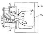
- FIG. 1is an end perspective view of a mold system in accordance with one exemplary but presently preferred embodiment of the invention
- FIG. 2is a perspective elevational view of two of the mold segments in the system of FIG. 1 ;
- FIGS. 3A and 3B togethercomprise a side elevational view of the mold segments illustrated in FIG. 2 ;
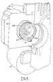
- FIG. 4is a fragmentary perspective view of the mold core and blow pin arrangement in FIG. 3A ;
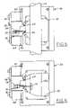
- FIGS. 5–8are schematic drawings that illustrate sequential stages of operation of the mold system in accordance with the embodiment of FIGS. 1–4 ;
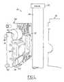
- FIG. 9is a schematic diagram of a continuous extrusion wheel-type machine in which the illustrated exemplary embodiment of the invention may be implemented.
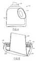
- FIG. 10is a fragmentary schematic drawing that illustrates a second exemplary implementation of the invention.
- FIG. 11is an elevational view of an exemplary container fabricated in accordance with FIGS. 1–8 ;
- FIG. 12is an enlarged sectional view of a portion of the container in FIG. 11 ;
- FIG. 13is a perspective view of a container made with the mold system of FIG. 10 ;
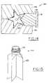
- FIG. 14is a fragmentary sectional view that illustrates a third exemplary implementation of the invention.
- FIG. 15is a perspective view of a star-shaped container molded in the apparatus of FIG. 14 .
- FIG. 1illustrates a mold system 20 in accordance with one presently preferred embodiment of the invention as comprising an extruder 22 for extruding a hollow continuous tube 24 of plastic material.
- tube 24may comprise a monolayer tube, or may comprise a multilayer tube that includes barrier resin layers, adhesive layers, regrind layers, post consumer resin layers, etc. for obtaining desired characteristics in the final container.
- Tube 24is typically, but not necessarily, of cylindrical geometry, and is typically, but not necessarily, of uniform wall thickness throughout its length and circumference.
- a first mold segment 26 , a second mold segment 28 and a third mold segment 30are mounted adjacent to the path of tube 24 .
- At least two of the mold segmentsare movable with respect to each other with respect to mold segment 28 and with respect to the axis of tube 24 between an open position illustrated in FIG. 1 that permits passage of tube 24 between the mold segments, and a closed position in which the mold segments cooperate to form a closed mold cavity 32 ( FIGS. 3A and 3B ) for blow-molding a container.
- first mold segment 26comprises a mold core that is movably mounted on second mold segment 28 .
- Mold core segment 26includes a mold core block 34 ( FIGS. 1–3A and 4 ) supported by a bridge plate 36 between the piston rods 38 , 40 of a pair of pneumatic cylinders 42 , 44 .
- Pneumatic cylinders 42 , 44are mounted on an end surface of mold segment 28 .
- Core block 34includes an opening that is closed by a cylinder cap 48 ( FIG. 3A ) to form a hollow cylinder cavity 46 .
- a piston assembly 50includes a piston body 52 slidable within cavity 46 .
- a hollow blow needle or pin 54extends from piston body 52 through a passage 56 in core block 34 .
- Blow pin 54has a sharpened end for piercing the wall of the extruded tube, as will be described.
- a guide pin 58also extends from piston body 52 , and is received in an opening 60 in core block 34 for maintaining the desired orientation of piston body 52 and blow pin 54 .
- Piston body 52has annular seals for sealing engagement with the opposing internal surface of cylinder cavity 46 .
- cylinder cap 48has seals for engaging the opposing surface of core block 34 to seal the internal cylinder cavity.
- a pair of air passages 61 , 62extend from the outer surface of core block 36 to the opposite ends of cavity 46 . (Directional words such as “inner” and “outer” are taken with respect to the mold cavity formed by the mold segments.)
- Core block 34 in the illustrated embodiment of the inventionhas an annular collar 64 (FIGS. 3 A and 4 – 8 ) that extends into mold cavity 32 in the fully extended position of core block 34 illustrated in FIGS. 3 A and 5 – 7 .
- collar 64clears mold cavity 72 to permit removal of the container.
- Collar 64is generally cylindrical in geometry, and has an inner end disposed in a plane at an angle to the axis of the collar for molding a drainback ledge on the container finish, as will be described.
- Mold core collar 64is selectively movable by cylinders 42 , 44 into and out of an opening 66 formed by opposed mold segments 28 , 30 between the fully extended position illustrated in FIGS.
- Mold core collar 64has a radially inwardly facing conical surface 64 a for forming the container spout, and a radially outwardly facing substantially cylindrical surface 64 b with grooves for forming internal threads on the container collar.
- Blow pin passage 56opens at the maximum height of collar 64 , which will be the low point of the drainage channel in the formed container.
- FIGS. 2 and 3Aillustrate fluid inlet and outlet to mold segments 26 , 28 .
- Mold coolantis fed to mold segment 28 (and mold segment 30 in FIG. 1 ) through an inlet 70 , an outlet 72 and mold coolant passages 74 ( FIGS. 3A and 3B ).
- Each pneumatic cylinder 42 , 44receives drive air through an associated pair of lines 76 , 78 .
- Cylinders 42 , 44operate in unison, as will be described.
- Blow pin airis fed through a fitting 80 ( FIGS. 2 and 3A ) mounted on piston 52 , and through the hollow interior of the blow pin into the mold cavity. Vent air is fed from the mold cavity through openings 68 (FIGS.
- Blow pin cylinder cavity 46receives air through passages 61 , 62 ( FIG. 3A ), as previously described, for moving the blow pin assembly, which includes blow pin piston 52 , blow pin 54 , guide pin 58 and fitting 80 , between the fully retracted position illustrated in FIGS. 3A , 5 and 8 , and the fully extended position illustrated in FIGS. 4 and 6 – 7 .
- the mold coolantmay be of any suitable type. Cylinders 42 , 44 preferably are pneumatic, but could be hydraulic or electric. Likewise, blow pin piston/cylinder 52 , 46 preferably is pneumatic, but could be hydraulic or electric.
- the containerpreferably is blow molded by air at elevated pressure, although other gases could be employed to obtain particular internal surface characteristics in the molded container.
- mold system 20The sequence of operation of mold system 20 is illustrated schematically in FIGS. 5–8 .
- the movement of mold segment 30is generally conventional in and of itself, and is not shown in FIGS. 5–8 to facilitate illustration.
- mold core 34In the starting position of FIG. 5 , mold core 34 is extended within mold section 26 to a position adjacent to tube 24 .
- mold section 30FIG. 1
- mold section 30FIG. 1
- Airis then applied to the blow pin cylinder to move blow pin 54 from the retracted position of FIG. 5 to the extended position of FIG. 6 , in which blow pin 54 pierces the wall of tube 24 .
- Blow airis then fed through pin 54 into the portion 24 d of tube 24 captured between the mold segments to expand the captured portion of tube 24 and blow mold the tube to the internal confines of mold cavity 32 .
- the blow-molded container 24 a so formedis illustrated in FIG. 7 .
- the air from cavity 32 that is displaced by expansion of the tubeis vented through vent openings 68 ( FIGS. 3A and 4 ), passages 81 ( FIG. 3A ) and vent outlet fitting 82 ( FIG. 2 ).
- core block 34may be moved by cylinders 42 , 44 to the retracted position illustrated in FIG. 8 , and blow pin 34 may be moved to the retracted position with respect to the core block as illustrated in FIG. 8 to leave a drainback opening 24 d .
- Mold segment 30is likewise moved to a retracted position spaced from mold segment 28 as illustrated in FIG. 1 , such as by operation of cylinders 99 ( FIG. 2 ).
- Container body 24 acan then be removed from between the mold segments.
- the dome 24 b of container body 24 awhich is molded within collar 64 on mold core 34 , is sliced as along the line 24 c to form a container pour spout.
- the containeris then ready for use as a drainback-type container of the type illustrated in above-noted U.S. Pat. No. 5,207,356, etc.
- the angulated end of core block collar 64forms an angulated surface beneath the spout for capturing any liquid that may drip from the end of the spout during use. This liquid is returned to the internal volume of the container through an opening at the low point of this drainback surface, which opening has been formed by blow pin 54 .
- FIGS. 11 and 12illustrate a container 110 as molded in accordance with the 20 method and system of FIGS. 1–8 and trimmed along plane 24 c ( FIG. 8 ).
- Container 110includes a hollow body 112 with a handle 113 and an integrally blow molded finish 114 .
- the finishhas an annular exterior portion 115 forming an axial extension of body 112 .
- An annular reentry portion 116extends within exterior portion 115 , and has one or more internal threads 118 for receiving a closure.
- An annular ledge portion 120extends radially inwardly from an end of reentry portion 116 .
- An annular spout portion 122extends axially outwardly from ledge portion 120 .
- Ledge portion 120is at an angle to the axis of spout portion 122 , and the drainback opening 124 formed by blow pin 54 ( FIGS. 3A and 7 ) is at the low point of the ledge portion.
- the bottleis essentially completed as molded, only requiring trimming along plane 24 c ( FIG. 8 ).
- FIG. 9illustrates a preferred implementation of the exemplary embodiment of the invention in a continuous extrusion wheel-type molding machine 90 .
- a plurality of mold segments 28are mounted in fixed position around the periphery of a wheel 92 .
- Each mold segment 28carries an associated mold core segment 26 .
- a plurality of mold segments 30are movable with respect to their associated fixed mold segments 28 radially inwardly and outwardly with respect to the axis of rotation of wheel 92 , such as by operation of cylinders 99 ( FIG. 2 ).
- Extruder 22provides tube 24 of plastic material between mold segments 28 , 30 at the three o'clock position of machine 90 .
- Mold segment 30is then closed against mold segment 28 as the wheel continues rotation, blow air is applied to the mold cavity, and the molded container body is allowed to cool as the wheel rotates the mold pair in the direction 95 to about the nine o'clock position.
- the mold segmentsopen, mold core segment 26 having already been retracted, and the container can be removed onto a conveyor 98 for further processing.
- the machine 90 in FIG. 9also includes an in-mold labeling mechanism 94 for placing labels into mold segment 28 and/or 30 for securement to the container when the container is subsequently molded against the internal confines of the mold cavity.
- FIG. 10illustrates a modified mold system 100 , in which reference numerals identical to those in FIGS. 1–8 illustrate identical or similar components.
- a mold core 102is mounted on a mold segment 104 by means of cylinders 42 , 44 and plate 36 .
- Mold segment 104 and an opposing mold segmentform a mold cavity 106 .
- the axis of cavity 106is parallel to the axis of the outlet portion of the final container.
- the axis of cavity 106is also parallel to the axis of extruded tube 24 , rather than perpendicular to the axis of the tube as in FIGS. 1–8 .
- Mold core 102is extendable into cavity 106 to form a pocket 108 in the side of the container for storage of a trigger spray head, for example, for home and garden applications (e.g., weed killer).
- FIG. 13illustrates an exemplary container 130 molded with the system of FIG. 10 .
- the container body 132 and finish 134have a mold parting line 136 .
- Pocket 108is formed in a container sidewall on this parting line.
- System 100 of FIG. 10also illustrates a modification in which a blow needle or pin 110 is mounted on mold segment 104 rather than on mold core 102 .
- Blow pin 110extends into a portion of cavity 106 that will form a moil on the outlet portion of the container, which will be removed in a post-mold trimming operation.
- Blow pin 110may be either stationarily or movably mounted on mold segment 104 .
- a vacuum aperturemay be disposed around or adjacent to the blow pin, as disclosed for example in U.S. Pat. Nos. 5,851,479 and 6,048,192, to draw the material of the tube over the blow pin.
- a second mold coreof the same or differing configuration as compared with mold core 102 , could be mounted on the opposite side of mold segment 104 .
- FIG. 14illustrates a second modified mold system 140 in which the axis of the mold cavity 142 is parallel to, rather than perpendicular to, the axis of extruded tube 24 .
- Apparatus 140includes a pair of mold segments 144 , 146 and a mold core 148 carried by plate 36 that is movably mounted on mold segment 144 (or 146 ). Mold segments 144 , 146 and mold core 148 cooperate to define a five-pointed star-shaped mold cavity 142 . A six-pointed star-shaped mold cavity may require a second mold segment core 148 on mold segment 144 (or 146 ).
- FIG. 140illustrates a second modified mold system 140 in which the axis of the mold cavity 142 is parallel to, rather than perpendicular to, the axis of extruded tube 24 .
- Apparatus 140includes a pair of mold segments 144 , 146 and a mold core 148 carried by plate 36 that is movably mounted on mold segment 144
- FIG. 15illustrates a container 150 , having a star-shaped body 152 and a finish 154 , fabricated using mold system 140 .
- the present inventionthus enables molding of complex or oddly shaped container contours, such as star-shaped containers, that were not heretofore readily moldable in the art.
Landscapes
- Engineering & Computer Science (AREA)
- Manufacturing & Machinery (AREA)
- Mechanical Engineering (AREA)
- Moulds For Moulding Plastics Or The Like (AREA)
Abstract
Description
Claims (14)
Priority Applications (1)
| Application Number | Priority Date | Filing Date | Title |
|---|---|---|---|
| US10/439,061US7153127B2 (en) | 2003-05-15 | 2003-05-15 | Method and apparatus for blow molding hollow plastic containers |
Applications Claiming Priority (1)
| Application Number | Priority Date | Filing Date | Title |
|---|---|---|---|
| US10/439,061US7153127B2 (en) | 2003-05-15 | 2003-05-15 | Method and apparatus for blow molding hollow plastic containers |
Publications (2)
| Publication Number | Publication Date |
|---|---|
| US20060073233A1 US20060073233A1 (en) | 2006-04-06 |
| US7153127B2true US7153127B2 (en) | 2006-12-26 |
Family
ID=36125855
Family Applications (1)
| Application Number | Title | Priority Date | Filing Date |
|---|---|---|---|
| US10/439,061Expired - Fee RelatedUS7153127B2 (en) | 2003-05-15 | 2003-05-15 | Method and apparatus for blow molding hollow plastic containers |
Country Status (1)
| Country | Link |
|---|---|
| US (1) | US7153127B2 (en) |
Cited By (63)
| Publication number | Priority date | Publication date | Assignee | Title |
|---|---|---|---|---|
| US20100108635A1 (en)* | 2008-11-06 | 2010-05-06 | Richard Lawrence Horstman | Container with an integrated spout |
| US20120177876A1 (en)* | 2011-01-12 | 2012-07-12 | Saflex Polymers Ltd. | Hollow Article With Pillar Structural Members |
| US8251998B2 (en) | 2006-08-16 | 2012-08-28 | Biomet Sports Medicine, Llc | Chondral defect repair |
| US8273106B2 (en) | 2006-02-03 | 2012-09-25 | Biomet Sports Medicine, Llc | Soft tissue repair and conduit device |
| US8292921B2 (en) | 2006-02-03 | 2012-10-23 | Biomet Sports Medicine, Llc | Soft tissue repair device and associated methods |
| US8298262B2 (en) | 2006-02-03 | 2012-10-30 | Biomet Sports Medicine, Llc | Method for tissue fixation |
| US8303604B2 (en) | 2004-11-05 | 2012-11-06 | Biomet Sports Medicine, Llc | Soft tissue repair device and method |
| US8337525B2 (en) | 2006-02-03 | 2012-12-25 | Biomet Sports Medicine, Llc | Soft tissue repair device and associated methods |
| US8343227B2 (en) | 2009-05-28 | 2013-01-01 | Biomet Manufacturing Corp. | Knee prosthesis assembly with ligament link |
| US8361113B2 (en) | 2006-02-03 | 2013-01-29 | Biomet Sports Medicine, Llc | Method and apparatus for coupling soft tissue to a bone |
| US8409253B2 (en) | 2006-02-03 | 2013-04-02 | Biomet Sports Medicine, Llc | Soft tissue repair assembly and associated method |
| US8500818B2 (en) | 2006-09-29 | 2013-08-06 | Biomet Manufacturing, Llc | Knee prosthesis assembly with ligament link |
| US8506597B2 (en) | 2011-10-25 | 2013-08-13 | Biomet Sports Medicine, Llc | Method and apparatus for interosseous membrane reconstruction |
| US20130241119A1 (en)* | 2010-06-28 | 2013-09-19 | Gemini Group, Inc. | Side blowing molding apparatus and method |
| US8551140B2 (en) | 2004-11-05 | 2013-10-08 | Biomet Sports Medicine, Llc | Method and apparatus for coupling soft tissue to bone |
| US8562645B2 (en) | 2006-09-29 | 2013-10-22 | Biomet Sports Medicine, Llc | Method and apparatus for forming a self-locking adjustable loop |
| US8562647B2 (en) | 2006-09-29 | 2013-10-22 | Biomet Sports Medicine, Llc | Method and apparatus for securing soft tissue to bone |
| US8574235B2 (en) | 2006-02-03 | 2013-11-05 | Biomet Sports Medicine, Llc | Method for trochanteric reattachment |
| US20130300037A1 (en)* | 2011-01-14 | 2013-11-14 | Widalys Luz Desoto-Burt | Process For The Manufacture Of An Article Comprising a Recess |
| US8597327B2 (en) | 2006-02-03 | 2013-12-03 | Biomet Manufacturing, Llc | Method and apparatus for sternal closure |
| US8608777B2 (en) | 2006-02-03 | 2013-12-17 | Biomet Sports Medicine | Method and apparatus for coupling soft tissue to a bone |
| US8652171B2 (en) | 2006-02-03 | 2014-02-18 | Biomet Sports Medicine, Llc | Method and apparatus for soft tissue fixation |
| US8652172B2 (en) | 2006-02-03 | 2014-02-18 | Biomet Sports Medicine, Llc | Flexible anchors for tissue fixation |
| US8672969B2 (en) | 2006-09-29 | 2014-03-18 | Biomet Sports Medicine, Llc | Fracture fixation device |
| US8672968B2 (en) | 2006-09-29 | 2014-03-18 | Biomet Sports Medicine, Llc | Method for implanting soft tissue |
| US8771352B2 (en) | 2011-05-17 | 2014-07-08 | Biomet Sports Medicine, Llc | Method and apparatus for tibial fixation of an ACL graft |
| US8801783B2 (en) | 2006-09-29 | 2014-08-12 | Biomet Sports Medicine, Llc | Prosthetic ligament system for knee joint |
| US8840645B2 (en) | 2004-11-05 | 2014-09-23 | Biomet Sports Medicine, Llc | Method and apparatus for coupling soft tissue to a bone |
| US8932331B2 (en) | 2006-02-03 | 2015-01-13 | Biomet Sports Medicine, Llc | Method and apparatus for coupling soft tissue to bone |
| US8936621B2 (en) | 2006-02-03 | 2015-01-20 | Biomet Sports Medicine, Llc | Method and apparatus for forming a self-locking adjustable loop |
| US8968364B2 (en) | 2006-02-03 | 2015-03-03 | Biomet Sports Medicine, Llc | Method and apparatus for fixation of an ACL graft |
| US8998949B2 (en) | 2004-11-09 | 2015-04-07 | Biomet Sports Medicine, Llc | Soft tissue conduit device |
| US9017381B2 (en) | 2007-04-10 | 2015-04-28 | Biomet Sports Medicine, Llc | Adjustable knotless loops |
| US9078644B2 (en) | 2006-09-29 | 2015-07-14 | Biomet Sports Medicine, Llc | Fracture fixation device |
| US9149267B2 (en) | 2006-02-03 | 2015-10-06 | Biomet Sports Medicine, Llc | Method and apparatus for coupling soft tissue to a bone |
| US9271713B2 (en) | 2006-02-03 | 2016-03-01 | Biomet Sports Medicine, Llc | Method and apparatus for tensioning a suture |
| US9314241B2 (en) | 2011-11-10 | 2016-04-19 | Biomet Sports Medicine, Llc | Apparatus for coupling soft tissue to a bone |
| WO2016073242A1 (en) | 2014-11-04 | 2016-05-12 | Graham Packaging Company, L.P. | Blow molding machine with molds moved mechanically and without the aid of electrical, hydraulic or pneumatic devices |
| US9357991B2 (en) | 2011-11-03 | 2016-06-07 | Biomet Sports Medicine, Llc | Method and apparatus for stitching tendons |
| US9370350B2 (en) | 2011-11-10 | 2016-06-21 | Biomet Sports Medicine, Llc | Apparatus for coupling soft tissue to a bone |
| US9381013B2 (en) | 2011-11-10 | 2016-07-05 | Biomet Sports Medicine, Llc | Method for coupling soft tissue to a bone |
| US9538998B2 (en) | 2006-02-03 | 2017-01-10 | Biomet Sports Medicine, Llc | Method and apparatus for fracture fixation |
| US9572655B2 (en) | 2004-11-05 | 2017-02-21 | Biomet Sports Medicine, Llc | Method and apparatus for coupling soft tissue to a bone |
| US9615822B2 (en) | 2014-05-30 | 2017-04-11 | Biomet Sports Medicine, Llc | Insertion tools and method for soft anchor |
| US9700291B2 (en) | 2014-06-03 | 2017-07-11 | Biomet Sports Medicine, Llc | Capsule retractor |
| US9757119B2 (en) | 2013-03-08 | 2017-09-12 | Biomet Sports Medicine, Llc | Visual aid for identifying suture limbs arthroscopically |
| US9801708B2 (en) | 2004-11-05 | 2017-10-31 | Biomet Sports Medicine, Llc | Method and apparatus for coupling soft tissue to a bone |
| US9918826B2 (en) | 2006-09-29 | 2018-03-20 | Biomet Sports Medicine, Llc | Scaffold for spring ligament repair |
| US9918827B2 (en) | 2013-03-14 | 2018-03-20 | Biomet Sports Medicine, Llc | Scaffold for spring ligament repair |
| US9955980B2 (en) | 2015-02-24 | 2018-05-01 | Biomet Sports Medicine, Llc | Anatomic soft tissue repair |
| US9994368B2 (en) | 2012-10-30 | 2018-06-12 | The Procter & Gamble Company | Closure for a container |
| US10039543B2 (en) | 2014-08-22 | 2018-08-07 | Biomet Sports Medicine, Llc | Non-sliding soft anchor |
| US10136886B2 (en) | 2013-12-20 | 2018-11-27 | Biomet Sports Medicine, Llc | Knotless soft tissue devices and techniques |
| US10517587B2 (en) | 2006-02-03 | 2019-12-31 | Biomet Sports Medicine, Llc | Method and apparatus for forming a self-locking adjustable loop |
| US10912551B2 (en) | 2015-03-31 | 2021-02-09 | Biomet Sports Medicine, Llc | Suture anchor with soft anchor of electrospun fibers |
| US11007757B2 (en) | 2019-03-15 | 2021-05-18 | Graham Packaging Company, L.P. | Light-weighting with dual resins in a multi-layer bottle |
| US11259794B2 (en) | 2006-09-29 | 2022-03-01 | Biomet Sports Medicine, Llc | Method for implanting soft tissue |
| US11259792B2 (en) | 2006-02-03 | 2022-03-01 | Biomet Sports Medicine, Llc | Method and apparatus for coupling anatomical features |
| US11311287B2 (en) | 2006-02-03 | 2022-04-26 | Biomet Sports Medicine, Llc | Method for tissue fixation |
| US12096928B2 (en) | 2009-05-29 | 2024-09-24 | Biomet Sports Medicine, Llc | Method and apparatus for coupling soft tissue to a bone |
| US12245759B2 (en) | 2008-08-22 | 2025-03-11 | Biomet Sports Medicine, Llc | Method and apparatus for coupling soft tissue to bone |
| US12329373B2 (en) | 2011-05-02 | 2025-06-17 | Biomet Sports Medicine, Llc | Method and apparatus for soft tissue fixation |
| US12419632B2 (en) | 2008-08-22 | 2025-09-23 | Biomet Sports Medicine, Llc | Method and apparatus for coupling anatomical features |
Families Citing this family (1)
| Publication number | Priority date | Publication date | Assignee | Title |
|---|---|---|---|---|
| US20120228312A1 (en)* | 2009-09-07 | 2012-09-13 | Daniel Sutherland | Bottle |
Citations (33)
| Publication number | Priority date | Publication date | Assignee | Title |
|---|---|---|---|---|
| US2515093A (en) | 1949-03-23 | 1950-07-11 | Elmer E Mills | Machine for making hollow articles |
| US2579390A (en) | 1949-03-23 | 1951-12-18 | Elmer E Mills | Method of making hollow articles |
| US3004285A (en)* | 1958-07-26 | 1961-10-17 | Reinold Hagen | Hollow plastic articles and their manufacture |
| US3339232A (en)* | 1963-07-08 | 1967-09-05 | Battenfeld Werner | Apparatus for the production of hollow bodies in a blowing process |
| US3342916A (en)* | 1965-05-04 | 1967-09-19 | Phillips Petroleum Co | Method and apparatus for blow molding hollow articles |
| US3440996A (en)* | 1964-04-20 | 1969-04-29 | Montedison Spa | Road signal fixture |
| US3672799A (en)* | 1970-07-17 | 1972-06-27 | Container Corp | Apparatus for forming a stackable container |
| US3915611A (en) | 1972-07-18 | 1975-10-28 | Phillips Petroleum Co | Blow molding apparatus |
| US3973896A (en)* | 1975-06-12 | 1976-08-10 | Phillips Petroleum Company | Blow molding apparatus |
| US4025276A (en)* | 1976-02-13 | 1977-05-24 | Phillips Petroleum Company | Blow molding apparatus |
| US4035461A (en)* | 1973-08-16 | 1977-07-12 | Krauss-Maffei Aktiengesellschaft | Method of making an extravertable-wall container |
| US4120927A (en)* | 1976-05-10 | 1978-10-17 | Beckman Instruments, Inc. | Process for making a one piece rotor liner |
| US4510116A (en)* | 1983-07-27 | 1985-04-09 | Phillips Petroleum Company | Apparatus and method for blow molding |
| US4523904A (en) | 1984-03-28 | 1985-06-18 | Owens-Illinois, Inc. | Blow molding apparatus |
| US4549865A (en) | 1984-03-28 | 1985-10-29 | Owens-Illinois, Inc. | Blow molding apparatus |
| US4648831A (en) | 1984-03-28 | 1987-03-10 | Owens-Illinois, Inc. | Blow molding apparatus |
| US4799876A (en) | 1988-02-22 | 1989-01-24 | Phillips Petroleum Company | Blow molding apparatus |
| US4989757A (en) | 1988-02-25 | 1991-02-05 | Owens-Illinois Plastic Products Inc. | Plastic container with self-draining feature |
| US5071037A (en) | 1989-09-14 | 1991-12-10 | Graham Engineering Corporation | Blow molded bottle with integral pour spout |
| US5078948A (en) | 1991-04-30 | 1992-01-07 | Ford Motor Company | Arrowhead tip blow needle and method of using the needle to blow mold an article |
| US5114659A (en) | 1988-02-25 | 1992-05-19 | Owens-Illinois Plastic Products Inc. | Blow molding method for forming a one-piece self-draining container |
| US5207356A (en) | 1988-02-25 | 1993-05-04 | Owens-Illinois Plastic Products Inc. | Self-draining container |
| US5249786A (en) | 1991-03-19 | 1993-10-05 | British Gas Plc | Pipe restraint system |
| US5551860A (en) | 1993-06-18 | 1996-09-03 | Dow Brands L.P. | Quick bottle production changeover utilizing multi-cavity molds in an extrusion blow molding system |
| US5645870A (en) | 1995-08-02 | 1997-07-08 | Owens-Brockway Plastic Products Inc. | Blow molding apparatus having a cylindrical hub |
| US5759475A (en) | 1992-10-26 | 1998-06-02 | Toyo Seikan Kaisya, Ltd. | Method for blow-molding hollow container and blow air cylinder |
| US5851479A (en) | 1996-12-24 | 1998-12-22 | Owens-Brockway Plastic Products Inc. | Method and apparatus for blow molding hollow articles |
| US5863489A (en) | 1996-10-25 | 1999-01-26 | Menza Limited | Method of blow-moulding |
| US5939108A (en) | 1996-07-08 | 1999-08-17 | Toyo Seikan Kaisya, Ltd. | Blow air cylinder for blow-molding hollow container |
| US5939014A (en) | 1995-08-01 | 1999-08-17 | Owens-Brockway Plastic Products Inc. | Method of removing hollow containers from a blow molding machine |
| US6123231A (en) | 1998-07-13 | 2000-09-26 | Owens-Brockway Plastic Products Inc. | Plastic container with drain back spout and method and apparatus for making same |
| US6143235A (en)* | 1997-08-02 | 2000-11-07 | Daimlerchrysler Ag | Method for producing secondary mold elements |
| JP2002192607A (en)* | 2000-12-27 | 2002-07-10 | Yoshino Kogyosho Co Ltd | Vessel with undercut and blow molding mold suitable for molding the vessel |
- 2003
- 2003-05-15USUS10/439,061patent/US7153127B2/ennot_activeExpired - Fee Related
Patent Citations (36)
| Publication number | Priority date | Publication date | Assignee | Title |
|---|---|---|---|---|
| US2515093A (en) | 1949-03-23 | 1950-07-11 | Elmer E Mills | Machine for making hollow articles |
| US2579390A (en) | 1949-03-23 | 1951-12-18 | Elmer E Mills | Method of making hollow articles |
| US3004285A (en)* | 1958-07-26 | 1961-10-17 | Reinold Hagen | Hollow plastic articles and their manufacture |
| US3339232A (en)* | 1963-07-08 | 1967-09-05 | Battenfeld Werner | Apparatus for the production of hollow bodies in a blowing process |
| US3440996A (en)* | 1964-04-20 | 1969-04-29 | Montedison Spa | Road signal fixture |
| US3342916A (en)* | 1965-05-04 | 1967-09-19 | Phillips Petroleum Co | Method and apparatus for blow molding hollow articles |
| US3792143A (en)* | 1965-05-04 | 1974-02-12 | Phillips Petroleum Co | Method for blow molding a hollow article having an attached hollow adjunct |
| US3672799A (en)* | 1970-07-17 | 1972-06-27 | Container Corp | Apparatus for forming a stackable container |
| US3915611A (en) | 1972-07-18 | 1975-10-28 | Phillips Petroleum Co | Blow molding apparatus |
| US4035461A (en)* | 1973-08-16 | 1977-07-12 | Krauss-Maffei Aktiengesellschaft | Method of making an extravertable-wall container |
| US3973896A (en)* | 1975-06-12 | 1976-08-10 | Phillips Petroleum Company | Blow molding apparatus |
| US4025276A (en)* | 1976-02-13 | 1977-05-24 | Phillips Petroleum Company | Blow molding apparatus |
| US4120927A (en)* | 1976-05-10 | 1978-10-17 | Beckman Instruments, Inc. | Process for making a one piece rotor liner |
| US4510116A (en)* | 1983-07-27 | 1985-04-09 | Phillips Petroleum Company | Apparatus and method for blow molding |
| US4523904A (en) | 1984-03-28 | 1985-06-18 | Owens-Illinois, Inc. | Blow molding apparatus |
| US4549865A (en) | 1984-03-28 | 1985-10-29 | Owens-Illinois, Inc. | Blow molding apparatus |
| US4648831A (en) | 1984-03-28 | 1987-03-10 | Owens-Illinois, Inc. | Blow molding apparatus |
| US4799876A (en) | 1988-02-22 | 1989-01-24 | Phillips Petroleum Company | Blow molding apparatus |
| US4989757A (en) | 1988-02-25 | 1991-02-05 | Owens-Illinois Plastic Products Inc. | Plastic container with self-draining feature |
| US5114659A (en) | 1988-02-25 | 1992-05-19 | Owens-Illinois Plastic Products Inc. | Blow molding method for forming a one-piece self-draining container |
| US5207356A (en) | 1988-02-25 | 1993-05-04 | Owens-Illinois Plastic Products Inc. | Self-draining container |
| US5429789A (en) | 1988-02-25 | 1995-07-04 | Owens-Illinois Plastic Products Inc. | Plastic container with self-draining feature |
| US5071037A (en) | 1989-09-14 | 1991-12-10 | Graham Engineering Corporation | Blow molded bottle with integral pour spout |
| US5249786A (en) | 1991-03-19 | 1993-10-05 | British Gas Plc | Pipe restraint system |
| US5078948A (en) | 1991-04-30 | 1992-01-07 | Ford Motor Company | Arrowhead tip blow needle and method of using the needle to blow mold an article |
| US5759475A (en) | 1992-10-26 | 1998-06-02 | Toyo Seikan Kaisya, Ltd. | Method for blow-molding hollow container and blow air cylinder |
| US5551860A (en) | 1993-06-18 | 1996-09-03 | Dow Brands L.P. | Quick bottle production changeover utilizing multi-cavity molds in an extrusion blow molding system |
| US5556648A (en) | 1993-06-18 | 1996-09-17 | Dowbrands Inc. | Quick bottle production changeover utilizing multi-cavity molds in an extrusion blow molding system |
| US5939014A (en) | 1995-08-01 | 1999-08-17 | Owens-Brockway Plastic Products Inc. | Method of removing hollow containers from a blow molding machine |
| US5645870A (en) | 1995-08-02 | 1997-07-08 | Owens-Brockway Plastic Products Inc. | Blow molding apparatus having a cylindrical hub |
| US5939108A (en) | 1996-07-08 | 1999-08-17 | Toyo Seikan Kaisya, Ltd. | Blow air cylinder for blow-molding hollow container |
| US5863489A (en) | 1996-10-25 | 1999-01-26 | Menza Limited | Method of blow-moulding |
| US5851479A (en) | 1996-12-24 | 1998-12-22 | Owens-Brockway Plastic Products Inc. | Method and apparatus for blow molding hollow articles |
| US6143235A (en)* | 1997-08-02 | 2000-11-07 | Daimlerchrysler Ag | Method for producing secondary mold elements |
| US6123231A (en) | 1998-07-13 | 2000-09-26 | Owens-Brockway Plastic Products Inc. | Plastic container with drain back spout and method and apparatus for making same |
| JP2002192607A (en)* | 2000-12-27 | 2002-07-10 | Yoshino Kogyosho Co Ltd | Vessel with undercut and blow molding mold suitable for molding the vessel |
Cited By (177)
| Publication number | Priority date | Publication date | Assignee | Title |
|---|---|---|---|---|
| US8551140B2 (en) | 2004-11-05 | 2013-10-08 | Biomet Sports Medicine, Llc | Method and apparatus for coupling soft tissue to bone |
| US11109857B2 (en) | 2004-11-05 | 2021-09-07 | Biomet Sports Medicine, Llc | Soft tissue repair device and method |
| US10265064B2 (en) | 2004-11-05 | 2019-04-23 | Biomet Sports Medicine, Llc | Soft tissue repair device and method |
| US9801708B2 (en) | 2004-11-05 | 2017-10-31 | Biomet Sports Medicine, Llc | Method and apparatus for coupling soft tissue to a bone |
| US9572655B2 (en) | 2004-11-05 | 2017-02-21 | Biomet Sports Medicine, Llc | Method and apparatus for coupling soft tissue to a bone |
| US9504460B2 (en) | 2004-11-05 | 2016-11-29 | Biomet Sports Medicine, LLC. | Soft tissue repair device and method |
| US8840645B2 (en) | 2004-11-05 | 2014-09-23 | Biomet Sports Medicine, Llc | Method and apparatus for coupling soft tissue to a bone |
| US8303604B2 (en) | 2004-11-05 | 2012-11-06 | Biomet Sports Medicine, Llc | Soft tissue repair device and method |
| US8998949B2 (en) | 2004-11-09 | 2015-04-07 | Biomet Sports Medicine, Llc | Soft tissue conduit device |
| US9561025B2 (en) | 2006-02-03 | 2017-02-07 | Biomet Sports Medicine, Llc | Soft tissue repair device and associated methods |
| US11896210B2 (en) | 2006-02-03 | 2024-02-13 | Biomet Sports Medicine, Llc | Method and apparatus for coupling soft tissue to a bone |
| US8361113B2 (en) | 2006-02-03 | 2013-01-29 | Biomet Sports Medicine, Llc | Method and apparatus for coupling soft tissue to a bone |
| US8409253B2 (en) | 2006-02-03 | 2013-04-02 | Biomet Sports Medicine, Llc | Soft tissue repair assembly and associated method |
| US11065103B2 (en) | 2006-02-03 | 2021-07-20 | Biomet Sports Medicine, Llc | Method and apparatus for fixation of an ACL graft |
| US10987099B2 (en) | 2006-02-03 | 2021-04-27 | Biomet Sports Medicine, Llc | Method for tissue fixation |
| US10973507B2 (en) | 2006-02-03 | 2021-04-13 | Biomet Sports Medicine, Llc | Method and apparatus for coupling soft tissue to a bone |
| US8337525B2 (en) | 2006-02-03 | 2012-12-25 | Biomet Sports Medicine, Llc | Soft tissue repair device and associated methods |
| US10932770B2 (en) | 2006-02-03 | 2021-03-02 | Biomet Sports Medicine, Llc | Soft tissue repair device and associated methods |
| US11116495B2 (en) | 2006-02-03 | 2021-09-14 | Biomet Sports Medicine, Llc | Soft tissue repair assembly and associated method |
| US8574235B2 (en) | 2006-02-03 | 2013-11-05 | Biomet Sports Medicine, Llc | Method for trochanteric reattachment |
| US10729421B2 (en) | 2006-02-03 | 2020-08-04 | Biomet Sports Medicine, Llc | Method and apparatus for soft tissue fixation |
| US8597327B2 (en) | 2006-02-03 | 2013-12-03 | Biomet Manufacturing, Llc | Method and apparatus for sternal closure |
| US8608777B2 (en) | 2006-02-03 | 2013-12-17 | Biomet Sports Medicine | Method and apparatus for coupling soft tissue to a bone |
| US8632569B2 (en) | 2006-02-03 | 2014-01-21 | Biomet Sports Medicine, Llc | Soft tissue repair device and associated methods |
| US8652171B2 (en) | 2006-02-03 | 2014-02-18 | Biomet Sports Medicine, Llc | Method and apparatus for soft tissue fixation |
| US8652172B2 (en) | 2006-02-03 | 2014-02-18 | Biomet Sports Medicine, Llc | Flexible anchors for tissue fixation |
| US10729430B2 (en) | 2006-02-03 | 2020-08-04 | Biomet Sports Medicine, Llc | Method and apparatus for coupling soft tissue to a bone |
| US10716557B2 (en) | 2006-02-03 | 2020-07-21 | Biomet Sports Medicine, Llc | Method and apparatus for coupling anatomical features |
| US8721684B2 (en) | 2006-02-03 | 2014-05-13 | Biomet Sports Medicine, Llc | Method and apparatus for coupling anatomical features |
| US8771316B2 (en) | 2006-02-03 | 2014-07-08 | Biomet Sports Medicine, Llc | Method and apparatus for coupling anatomical features |
| US10702259B2 (en) | 2006-02-03 | 2020-07-07 | Biomet Sports Medicine, Llc | Soft tissue repair assembly and associated method |
| US10004588B2 (en) | 2006-02-03 | 2018-06-26 | Biomet Sports Medicine, Llc | Method and apparatus for fixation of an ACL graft |
| US10695052B2 (en) | 2006-02-03 | 2020-06-30 | Biomet Sports Medicine, Llc | Method and apparatus for coupling soft tissue to a bone |
| US8298262B2 (en) | 2006-02-03 | 2012-10-30 | Biomet Sports Medicine, Llc | Method for tissue fixation |
| US10687803B2 (en) | 2006-02-03 | 2020-06-23 | Biomet Sports Medicine, Llc | Method and apparatus for coupling soft tissue to a bone |
| US8932331B2 (en) | 2006-02-03 | 2015-01-13 | Biomet Sports Medicine, Llc | Method and apparatus for coupling soft tissue to bone |
| US8936621B2 (en) | 2006-02-03 | 2015-01-20 | Biomet Sports Medicine, Llc | Method and apparatus for forming a self-locking adjustable loop |
| US8968364B2 (en) | 2006-02-03 | 2015-03-03 | Biomet Sports Medicine, Llc | Method and apparatus for fixation of an ACL graft |
| US8292921B2 (en) | 2006-02-03 | 2012-10-23 | Biomet Sports Medicine, Llc | Soft tissue repair device and associated methods |
| US9005287B2 (en) | 2006-02-03 | 2015-04-14 | Biomet Sports Medicine, Llc | Method for bone reattachment |
| US10675073B2 (en) | 2006-02-03 | 2020-06-09 | Biomet Sports Medicine, Llc | Method and apparatus for sternal closure |
| US10603029B2 (en) | 2006-02-03 | 2020-03-31 | Biomet Sports Medicine, Llc | Method and apparatus for coupling soft tissue to bone |
| US9149267B2 (en) | 2006-02-03 | 2015-10-06 | Biomet Sports Medicine, Llc | Method and apparatus for coupling soft tissue to a bone |
| US10595851B2 (en) | 2006-02-03 | 2020-03-24 | Biomet Sports Medicine, Llc | Method and apparatus for coupling soft tissue to a bone |
| US9173651B2 (en) | 2006-02-03 | 2015-11-03 | Biomet Sports Medicine, Llc | Soft tissue repair device and associated methods |
| US10542967B2 (en) | 2006-02-03 | 2020-01-28 | Biomet Sports Medicine, Llc | Method and apparatus for coupling soft tissue to a bone |
| US9271713B2 (en) | 2006-02-03 | 2016-03-01 | Biomet Sports Medicine, Llc | Method and apparatus for tensioning a suture |
| US12096931B2 (en) | 2006-02-03 | 2024-09-24 | Biomet Sports Medicine, Llc | Method and apparatus for coupling soft tissue to a bone |
| US12064101B2 (en) | 2006-02-03 | 2024-08-20 | Biomet Sports Medicine, Llc | Method and apparatus for forming a self-locking adjustable loop |
| US9603591B2 (en) | 2006-02-03 | 2017-03-28 | Biomet Sports Medicine, Llc | Flexible anchors for tissue fixation |
| US10004489B2 (en) | 2006-02-03 | 2018-06-26 | Biomet Sports Medicine, Llc | Method and apparatus for coupling soft tissue to a bone |
| US11819205B2 (en) | 2006-02-03 | 2023-11-21 | Biomet Sports Medicine, Llc | Soft tissue repair device and associated methods |
| US11786236B2 (en) | 2006-02-03 | 2023-10-17 | Biomet Sports Medicine, Llc | Method and apparatus for coupling anatomical features |
| US11730464B2 (en) | 2006-02-03 | 2023-08-22 | Biomet Sports Medicine, Llc | Soft tissue repair assembly and associated method |
| US9402621B2 (en) | 2006-02-03 | 2016-08-02 | Biomet Sports Medicine, LLC. | Method for tissue fixation |
| US10517587B2 (en) | 2006-02-03 | 2019-12-31 | Biomet Sports Medicine, Llc | Method and apparatus for forming a self-locking adjustable loop |
| US9414833B2 (en) | 2006-02-03 | 2016-08-16 | Biomet Sports Medicine, Llc | Soft tissue repair assembly and associated method |
| US11723648B2 (en) | 2006-02-03 | 2023-08-15 | Biomet Sports Medicine, Llc | Method and apparatus for soft tissue fixation |
| US10441264B2 (en) | 2006-02-03 | 2019-10-15 | Biomet Sports Medicine, Llc | Soft tissue repair assembly and associated method |
| US9468433B2 (en) | 2006-02-03 | 2016-10-18 | Biomet Sports Medicine, Llc | Method and apparatus for forming a self-locking adjustable loop |
| US10398428B2 (en) | 2006-02-03 | 2019-09-03 | Biomet Sports Medicine, Llc | Method and apparatus for coupling anatomical features |
| US9492158B2 (en) | 2006-02-03 | 2016-11-15 | Biomet Sports Medicine, Llc | Method and apparatus for coupling soft tissue to a bone |
| US9498204B2 (en) | 2006-02-03 | 2016-11-22 | Biomet Sports Medicine, Llc | Method and apparatus for coupling anatomical features |
| US8273106B2 (en) | 2006-02-03 | 2012-09-25 | Biomet Sports Medicine, Llc | Soft tissue repair and conduit device |
| US9510821B2 (en) | 2006-02-03 | 2016-12-06 | Biomet Sports Medicine, Llc | Method and apparatus for coupling anatomical features |
| US9510819B2 (en) | 2006-02-03 | 2016-12-06 | Biomet Sports Medicine, Llc | Soft tissue repair device and associated methods |
| US9532777B2 (en) | 2006-02-03 | 2017-01-03 | Biomet Sports Medicine, Llc | Method and apparatus for coupling soft tissue to a bone |
| US11259792B2 (en) | 2006-02-03 | 2022-03-01 | Biomet Sports Medicine, Llc | Method and apparatus for coupling anatomical features |
| US9538998B2 (en) | 2006-02-03 | 2017-01-10 | Biomet Sports Medicine, Llc | Method and apparatus for fracture fixation |
| US11039826B2 (en) | 2006-02-03 | 2021-06-22 | Biomet Sports Medicine, Llc | Method and apparatus for forming a self-locking adjustable loop |
| US9993241B2 (en) | 2006-02-03 | 2018-06-12 | Biomet Sports Medicine, Llc | Method and apparatus for forming a self-locking adjustable loop |
| US9622736B2 (en) | 2006-02-03 | 2017-04-18 | Biomet Sports Medicine, Llc | Soft tissue repair device and associated methods |
| US11284884B2 (en) | 2006-02-03 | 2022-03-29 | Biomet Sports Medicine, Llc | Method and apparatus for coupling soft tissue to a bone |
| US11998185B2 (en) | 2006-02-03 | 2024-06-04 | Biomet Sports Medicine, Llc | Method and apparatus for coupling soft tissue to a bone |
| US9642661B2 (en) | 2006-02-03 | 2017-05-09 | Biomet Sports Medicine, Llc | Method and Apparatus for Sternal Closure |
| US11311287B2 (en) | 2006-02-03 | 2022-04-26 | Biomet Sports Medicine, Llc | Method for tissue fixation |
| US11617572B2 (en) | 2006-02-03 | 2023-04-04 | Biomet Sports Medicine, Llc | Soft tissue repair device and associated methods |
| US10321906B2 (en) | 2006-02-03 | 2019-06-18 | Biomet Sports Medicine, Llc | Method for tissue fixation |
| US11317907B2 (en) | 2006-02-03 | 2022-05-03 | Biomet Sports Medicine, Llc | Method and apparatus for forming a self-locking adjustable loop |
| US9763656B2 (en) | 2006-02-03 | 2017-09-19 | Biomet Sports Medicine, Llc | Method and apparatus for soft tissue fixation |
| US10251637B2 (en) | 2006-02-03 | 2019-04-09 | Biomet Sports Medicine, Llc | Soft tissue repair device and associated methods |
| US10154837B2 (en) | 2006-02-03 | 2018-12-18 | Biomet Sports Medicine, Llc | Method and apparatus for coupling soft tissue to a bone |
| US9801620B2 (en) | 2006-02-03 | 2017-10-31 | Biomet Sports Medicine, Llc | Method and apparatus for coupling soft tissue to bone |
| US10098629B2 (en) | 2006-02-03 | 2018-10-16 | Biomet Sports Medicine, Llc | Method and apparatus for coupling soft tissue to a bone |
| US10092288B2 (en) | 2006-02-03 | 2018-10-09 | Biomet Sports Medicine, Llc | Method and apparatus for coupling soft tissue to a bone |
| US11446019B2 (en) | 2006-02-03 | 2022-09-20 | Biomet Sports Medicine, Llc | Method and apparatus for coupling soft tissue to a bone |
| US11589859B2 (en) | 2006-02-03 | 2023-02-28 | Biomet Sports Medicine, Llc | Method and apparatus for coupling soft tissue to bone |
| US10022118B2 (en) | 2006-02-03 | 2018-07-17 | Biomet Sports Medicine, Llc | Method and apparatus for coupling soft tissue to a bone |
| US11471147B2 (en) | 2006-02-03 | 2022-10-18 | Biomet Sports Medicine, Llc | Method and apparatus for coupling soft tissue to a bone |
| US8251998B2 (en) | 2006-08-16 | 2012-08-28 | Biomet Sports Medicine, Llc | Chondral defect repair |
| US8777956B2 (en) | 2006-08-16 | 2014-07-15 | Biomet Sports Medicine, Llc | Chondral defect repair |
| US9078644B2 (en) | 2006-09-29 | 2015-07-14 | Biomet Sports Medicine, Llc | Fracture fixation device |
| US10349931B2 (en) | 2006-09-29 | 2019-07-16 | Biomet Sports Medicine, Llc | Fracture fixation device |
| US8500818B2 (en) | 2006-09-29 | 2013-08-06 | Biomet Manufacturing, Llc | Knee prosthesis assembly with ligament link |
| US9918826B2 (en) | 2006-09-29 | 2018-03-20 | Biomet Sports Medicine, Llc | Scaffold for spring ligament repair |
| US8562645B2 (en) | 2006-09-29 | 2013-10-22 | Biomet Sports Medicine, Llc | Method and apparatus for forming a self-locking adjustable loop |
| US9833230B2 (en) | 2006-09-29 | 2017-12-05 | Biomet Sports Medicine, Llc | Fracture fixation device |
| US11376115B2 (en) | 2006-09-29 | 2022-07-05 | Biomet Sports Medicine, Llc | Prosthetic ligament system for knee joint |
| US11096684B2 (en) | 2006-09-29 | 2021-08-24 | Biomet Sports Medicine, Llc | Method and apparatus for forming a self-locking adjustable loop |
| US10835232B2 (en) | 2006-09-29 | 2020-11-17 | Biomet Sports Medicine, Llc | Fracture fixation device |
| US9788876B2 (en) | 2006-09-29 | 2017-10-17 | Biomet Sports Medicine, Llc | Fracture fixation device |
| US8801783B2 (en) | 2006-09-29 | 2014-08-12 | Biomet Sports Medicine, Llc | Prosthetic ligament system for knee joint |
| US8562647B2 (en) | 2006-09-29 | 2013-10-22 | Biomet Sports Medicine, Llc | Method and apparatus for securing soft tissue to bone |
| US9724090B2 (en) | 2006-09-29 | 2017-08-08 | Biomet Manufacturing, Llc | Method and apparatus for attaching soft tissue to bone |
| US10695045B2 (en) | 2006-09-29 | 2020-06-30 | Biomet Sports Medicine, Llc | Method and apparatus for attaching soft tissue to bone |
| US9681940B2 (en) | 2006-09-29 | 2017-06-20 | Biomet Sports Medicine, Llc | Ligament system for knee joint |
| US10743925B2 (en) | 2006-09-29 | 2020-08-18 | Biomet Sports Medicine, Llc | Fracture fixation device |
| US9539003B2 (en) | 2006-09-29 | 2017-01-10 | Biomet Sports Medicine, LLC. | Method and apparatus for forming a self-locking adjustable loop |
| US9486211B2 (en) | 2006-09-29 | 2016-11-08 | Biomet Sports Medicine, Llc | Method for implanting soft tissue |
| US10398430B2 (en) | 2006-09-29 | 2019-09-03 | Biomet Sports Medicine, Llc | Method for implanting soft tissue |
| US10004493B2 (en) | 2006-09-29 | 2018-06-26 | Biomet Sports Medicine, Llc | Method for implanting soft tissue |
| US11259794B2 (en) | 2006-09-29 | 2022-03-01 | Biomet Sports Medicine, Llc | Method for implanting soft tissue |
| US9414925B2 (en) | 2006-09-29 | 2016-08-16 | Biomet Manufacturing, Llc | Method of implanting a knee prosthesis assembly with a ligament link |
| US10517714B2 (en) | 2006-09-29 | 2019-12-31 | Biomet Sports Medicine, Llc | Ligament system for knee joint |
| US8672969B2 (en) | 2006-09-29 | 2014-03-18 | Biomet Sports Medicine, Llc | Fracture fixation device |
| US8672968B2 (en) | 2006-09-29 | 2014-03-18 | Biomet Sports Medicine, Llc | Method for implanting soft tissue |
| US11672527B2 (en) | 2006-09-29 | 2023-06-13 | Biomet Sports Medicine, Llc | Method for implanting soft tissue |
| US10610217B2 (en) | 2006-09-29 | 2020-04-07 | Biomet Sports Medicine, Llc | Method and apparatus for forming a self-locking adjustable loop |
| US11612391B2 (en) | 2007-01-16 | 2023-03-28 | Biomet Sports Medicine, Llc | Soft tissue repair device and associated methods |
| US10729423B2 (en) | 2007-04-10 | 2020-08-04 | Biomet Sports Medicine, Llc | Adjustable knotless loops |
| US9017381B2 (en) | 2007-04-10 | 2015-04-28 | Biomet Sports Medicine, Llc | Adjustable knotless loops |
| US12303122B2 (en) | 2007-04-10 | 2025-05-20 | Biomet Sports Medicine, Llc | Adjustable knotless loops |
| US9861351B2 (en) | 2007-04-10 | 2018-01-09 | Biomet Sports Medicine, Llc | Adjustable knotless loops |
| US11185320B2 (en) | 2007-04-10 | 2021-11-30 | Biomet Sports Medicine, Llc | Adjustable knotless loops |
| US12245759B2 (en) | 2008-08-22 | 2025-03-11 | Biomet Sports Medicine, Llc | Method and apparatus for coupling soft tissue to bone |
| US11534159B2 (en) | 2008-08-22 | 2022-12-27 | Biomet Sports Medicine, Llc | Method and apparatus for coupling soft tissue to a bone |
| US12419632B2 (en) | 2008-08-22 | 2025-09-23 | Biomet Sports Medicine, Llc | Method and apparatus for coupling anatomical features |
| US7857168B2 (en)* | 2008-11-06 | 2010-12-28 | The Procter & Gamble Company | Container with an integrated spout |
| US20100108635A1 (en)* | 2008-11-06 | 2010-05-06 | Richard Lawrence Horstman | Container with an integrated spout |
| US20110062109A1 (en)* | 2008-11-06 | 2011-03-17 | Richard Lawrence Horstman | Container with an Integrated Spout |
| US10149767B2 (en) | 2009-05-28 | 2018-12-11 | Biomet Manufacturing, Llc | Method of implanting knee prosthesis assembly with ligament link |
| US8343227B2 (en) | 2009-05-28 | 2013-01-01 | Biomet Manufacturing Corp. | Knee prosthesis assembly with ligament link |
| US8900314B2 (en) | 2009-05-28 | 2014-12-02 | Biomet Manufacturing, Llc | Method of implanting a prosthetic knee joint assembly |
| US12251093B2 (en) | 2009-05-29 | 2025-03-18 | Biomet Sports Medicine, Llc | Method and apparatus for coupling soft tissue to a bone |
| US12096928B2 (en) | 2009-05-29 | 2024-09-24 | Biomet Sports Medicine, Llc | Method and apparatus for coupling soft tissue to a bone |
| US20130241119A1 (en)* | 2010-06-28 | 2013-09-19 | Gemini Group, Inc. | Side blowing molding apparatus and method |
| US9469064B2 (en)* | 2010-06-28 | 2016-10-18 | Gemini Group, Inc. | Side blowing molding apparatus and method |
| US9174382B2 (en)* | 2011-01-12 | 2015-11-03 | Salflex Polymers Ltd. | Hollow article with pillar structural members |
| US10357934B2 (en) | 2011-01-12 | 2019-07-23 | Abc Technologies Inc. | Hollow article with pillar structural members |
| US20120177876A1 (en)* | 2011-01-12 | 2012-07-12 | Saflex Polymers Ltd. | Hollow Article With Pillar Structural Members |
| US20130300037A1 (en)* | 2011-01-14 | 2013-11-14 | Widalys Luz Desoto-Burt | Process For The Manufacture Of An Article Comprising a Recess |
| US9321228B2 (en)* | 2011-01-14 | 2016-04-26 | The Procter & Gamble Company | Process for the manufacture of an article comprising a recess |
| US12329373B2 (en) | 2011-05-02 | 2025-06-17 | Biomet Sports Medicine, Llc | Method and apparatus for soft tissue fixation |
| US12336701B2 (en) | 2011-05-02 | 2025-06-24 | Biomet Sports Medicine, Llc | Method and apparatus for soft tissue fixation |
| US8771352B2 (en) | 2011-05-17 | 2014-07-08 | Biomet Sports Medicine, Llc | Method and apparatus for tibial fixation of an ACL graft |
| US9216078B2 (en) | 2011-05-17 | 2015-12-22 | Biomet Sports Medicine, Llc | Method and apparatus for tibial fixation of an ACL graft |
| US8506597B2 (en) | 2011-10-25 | 2013-08-13 | Biomet Sports Medicine, Llc | Method and apparatus for interosseous membrane reconstruction |
| US9445827B2 (en) | 2011-10-25 | 2016-09-20 | Biomet Sports Medicine, Llc | Method and apparatus for intraosseous membrane reconstruction |
| US11241305B2 (en) | 2011-11-03 | 2022-02-08 | Biomet Sports Medicine, Llc | Method and apparatus for stitching tendons |
| US9357991B2 (en) | 2011-11-03 | 2016-06-07 | Biomet Sports Medicine, Llc | Method and apparatus for stitching tendons |
| US10265159B2 (en) | 2011-11-03 | 2019-04-23 | Biomet Sports Medicine, Llc | Method and apparatus for stitching tendons |
| US9314241B2 (en) | 2011-11-10 | 2016-04-19 | Biomet Sports Medicine, Llc | Apparatus for coupling soft tissue to a bone |
| US10363028B2 (en) | 2011-11-10 | 2019-07-30 | Biomet Sports Medicine, Llc | Method for coupling soft tissue to a bone |
| US11534157B2 (en) | 2011-11-10 | 2022-12-27 | Biomet Sports Medicine, Llc | Method for coupling soft tissue to a bone |
| US9357992B2 (en) | 2011-11-10 | 2016-06-07 | Biomet Sports Medicine, Llc | Method for coupling soft tissue to a bone |
| US10368856B2 (en) | 2011-11-10 | 2019-08-06 | Biomet Sports Medicine, Llc | Apparatus for coupling soft tissue to a bone |
| US9370350B2 (en) | 2011-11-10 | 2016-06-21 | Biomet Sports Medicine, Llc | Apparatus for coupling soft tissue to a bone |
| US9381013B2 (en) | 2011-11-10 | 2016-07-05 | Biomet Sports Medicine, Llc | Method for coupling soft tissue to a bone |
| US9994368B2 (en) | 2012-10-30 | 2018-06-12 | The Procter & Gamble Company | Closure for a container |
| US9757119B2 (en) | 2013-03-08 | 2017-09-12 | Biomet Sports Medicine, Llc | Visual aid for identifying suture limbs arthroscopically |
| US9918827B2 (en) | 2013-03-14 | 2018-03-20 | Biomet Sports Medicine, Llc | Scaffold for spring ligament repair |
| US10758221B2 (en) | 2013-03-14 | 2020-09-01 | Biomet Sports Medicine, Llc | Scaffold for spring ligament repair |
| US10136886B2 (en) | 2013-12-20 | 2018-11-27 | Biomet Sports Medicine, Llc | Knotless soft tissue devices and techniques |
| US10806443B2 (en) | 2013-12-20 | 2020-10-20 | Biomet Sports Medicine, Llc | Knotless soft tissue devices and techniques |
| US11648004B2 (en) | 2013-12-20 | 2023-05-16 | Biomet Sports Medicine, Llc | Knotless soft tissue devices and techniques |
| US12251100B2 (en) | 2013-12-20 | 2025-03-18 | Biomet Sports Medicine, Llc | Knotless soft tissue devices and techniques |
| US9615822B2 (en) | 2014-05-30 | 2017-04-11 | Biomet Sports Medicine, Llc | Insertion tools and method for soft anchor |
| US9700291B2 (en) | 2014-06-03 | 2017-07-11 | Biomet Sports Medicine, Llc | Capsule retractor |
| US12193656B2 (en) | 2014-08-22 | 2025-01-14 | Biomet Sports Medicine, Llc | Non-sliding soft anchor |
| US11219443B2 (en) | 2014-08-22 | 2022-01-11 | Biomet Sports Medicine, Llc | Non-sliding soft anchor |
| US10039543B2 (en) | 2014-08-22 | 2018-08-07 | Biomet Sports Medicine, Llc | Non-sliding soft anchor |
| US10743856B2 (en) | 2014-08-22 | 2020-08-18 | Biomet Sports Medicine, Llc | Non-sliding soft anchor |
| US10442129B2 (en) | 2014-11-04 | 2019-10-15 | Simoparma Packing Italia, S.r.l. | Blow molding machine with molds moved mechanically and without the aid of electrical, hydraulic or pneumatic devices |
| WO2016073242A1 (en) | 2014-11-04 | 2016-05-12 | Graham Packaging Company, L.P. | Blow molding machine with molds moved mechanically and without the aid of electrical, hydraulic or pneumatic devices |
| US9955980B2 (en) | 2015-02-24 | 2018-05-01 | Biomet Sports Medicine, Llc | Anatomic soft tissue repair |
| US10912551B2 (en) | 2015-03-31 | 2021-02-09 | Biomet Sports Medicine, Llc | Suture anchor with soft anchor of electrospun fibers |
| US11007757B2 (en) | 2019-03-15 | 2021-05-18 | Graham Packaging Company, L.P. | Light-weighting with dual resins in a multi-layer bottle |
Also Published As
| Publication number | Publication date |
|---|---|
| US20060073233A1 (en) | 2006-04-06 |
Similar Documents
| Publication | Publication Date | Title |
|---|---|---|
| US7153127B2 (en) | Method and apparatus for blow molding hollow plastic containers | |
| US6203870B1 (en) | Liner and preform | |
| US4929410A (en) | Method for blow-molding a container having a neck-portion with internal attachment means | |
| US5840350A (en) | Modified plastic bottle injection blow-molding apparatus and method | |
| CA1242858A (en) | Expandable core pin for blow-molding a container having a neck-portion with internal attachment means | |
| JPS62181130A (en) | Process for molding hollow container with handgrip | |
| US3806300A (en) | Apparatus for forming the neck on a plastic container | |
| US3940225A (en) | Blow molding apparatus for staged inflation of an extruded parison | |
| US20070272652A1 (en) | Integral Handle Pet Container System | |
| CA1074970A (en) | Method of blow molding | |
| US7141202B2 (en) | Method and apparatus for blow molding a bottle with a punched hole in a molded neck recess | |
| KR101069912B1 (en) | delaminated bottle manufacturing process and for a delaminated bottle | |
| US20040159983A1 (en) | Method and apparatus for blow-molding an article having a solid radially outwardly projecting flange | |
| EP0241040A1 (en) | Manufacture of plastic bottles | |
| US6077471A (en) | Mold for forming a container having a continuous neck finish and method for using same | |
| US3608021A (en) | Method and apparatus for blow molding and trimming plastic articles | |
| EP3150356B1 (en) | Composite container manufacturing method, molding die, and composite container | |
| JPH11147249A (en) | Blow molded product and blow molding method | |
| US12296523B2 (en) | Method of forming a container having a hanging implement | |
| US8523557B2 (en) | Blow needle for extrusion blow molding PET | |
| CN215703995U (en) | Lip mould for bottle blowing machine | |
| US11040475B2 (en) | Vertically added processing for blow molding machine | |
| WO2023249611A1 (en) | Parison and method for forming a container including an internal tapered base | |
| CN208164272U (en) | A kind of blowing device of infusion bottle | |
| WO2023249610A1 (en) | Container including an internal tapered base |
Legal Events
| Date | Code | Title | Description |
|---|---|---|---|
| AS | Assignment | Owner name:OWENS-BROCKWAY PLASTIC PRODUCTS, INC., OHIO Free format text:ASSIGNMENT OF ASSIGNORS INTEREST;ASSIGNORS:STRUBLE, DOUGLAS S.;SAFIAN, JOHN W.;REEL/FRAME:014085/0756;SIGNING DATES FROM 20030501 TO 20030505 | |
| AS | Assignment | Owner name:GRAHAM PACKAGING PLASTIC PRODUCTS INC., PENNSYLVAN Free format text:CHANGE OF NAME;ASSIGNOR:OWENS-BROCKWAY PLASTIC PRODUCTS INC.;REEL/FRAME:017946/0345 Effective date:20041021 | |
| AS | Assignment | Owner name:DEUTSCHE BANK AG CAYMAN ISLANDS BRANCH AS SECOND-L Free format text:GRANT OF SECURITY INTEREST;ASSIGNOR:GRAHAM PACKAGING COMPANY, L.P.;REEL/FRAME:015552/0299 Effective date:20041007 Owner name:DEUTSCHE BANK AG CAYMAN ISLANDS BRANCH, NEW JERSEY Free format text:GRANT OF SECURITY INTEREST;ASSIGNOR:GRAHAM PACKAGING COMPANY, L.P.;REEL/FRAME:015980/0213 Effective date:20041007 | |
| FPAY | Fee payment | Year of fee payment:4 | |
| AS | Assignment | Owner name:GRAHAM PACKAGING COMPANY, L.P., PENNSYLVANIA Free format text:RELEASE OF SECURITY INTERESTS;ASSIGNOR:DEUTSCHE BANK AG, GAYMAN ISLANDS BRANCH, AS COLLATERAL AGENT;REEL/FRAME:027011/0572 Effective date:20110908 | |
| AS | Assignment | Owner name:REYNOLDS GROUP HOLDINGS INC., NEW ZEALAND Free format text:SECURITY AGREEMENT;ASSIGNOR:GRAHAM PACKAGING PLASTIC PRODUCTS INC.;REEL/FRAME:026970/0750 Effective date:20110908 | |
| AS | Assignment | Owner name:THE BANK OF NEW YORK MELLON, NEW YORK Free format text:PATENT SECURITY AGREEMENT;ASSIGNOR:GRAHAM PACKAGING PLASTIC PRODUCTS INC.;REEL/FRAME:027910/0639 Effective date:20120320 Owner name:GRAHAM PACKAGING PLASTIC PRODUCTS INC., PENNSYLVAN Free format text:TERMINATION AND RELEASE OF SECURITY INTEREST IN PATENTS;ASSIGNOR:REYNOLDS GROUP HOLDINGS INC.;REEL/FRAME:027910/0549 Effective date:20120320 | |
| FPAY | Fee payment | Year of fee payment:8 | |
| FEPP | Fee payment procedure | Free format text:MAINTENANCE FEE REMINDER MAILED (ORIGINAL EVENT CODE: REM.) | |
| LAPS | Lapse for failure to pay maintenance fees | Free format text:PATENT EXPIRED FOR FAILURE TO PAY MAINTENANCE FEES (ORIGINAL EVENT CODE: EXP.); ENTITY STATUS OF PATENT OWNER: LARGE ENTITY | |
| STCH | Information on status: patent discontinuation | Free format text:PATENT EXPIRED DUE TO NONPAYMENT OF MAINTENANCE FEES UNDER 37 CFR 1.362 | |
| FP | Lapsed due to failure to pay maintenance fee | Effective date:20181226 | |
| AS | Assignment | Owner name:GRAHAM PACKAGING PLASTIC PRODUCTS INC., PENNSYLVANIA Free format text:RELEASE OF SECURITY INTEREST IN CERTAIN PATENT COLLATERAL;ASSIGNOR:THE BANK OF NEW YORK MELLON, AS THE COLLATERAL AGENT AND TRUSTEE;REEL/FRAME:053396/0696 Effective date:20200804 | |
| AS | Assignment | Owner name:GRAHAM PACKAGING COMPANY, L.P., PENNSYLVANIA Free format text:RELEASE OF SECURITY INTEREST IN CERTAIN PATENT COLLATERAL;ASSIGNOR:DEUTSCHE BANK AG CAYMAN ISLANDS BRANCH, AS COLLATERAL AGENT AND GRANTEE;REEL/FRAME:053414/0001 Effective date:20200805 |