US7153047B2 - Systematic lenticular lens selection in a digital printing environment - Google Patents
Systematic lenticular lens selection in a digital printing environmentDownload PDFInfo
- Publication number
- US7153047B2 US7153047B2US11/113,662US11366205AUS7153047B2US 7153047 B2US7153047 B2US 7153047B2US 11366205 AUS11366205 AUS 11366205AUS 7153047 B2US7153047 B2US 7153047B2
- Authority
- US
- United States
- Prior art keywords
- resolution
- interlaced image
- image
- lenticular lens
- master
- Prior art date
- Legal status (The legal status is an assumption and is not a legal conclusion. Google has not performed a legal analysis and makes no representation as to the accuracy of the status listed.)
- Expired - Lifetime, expires
Links
Images


Classifications
- H—ELECTRICITY
- H04—ELECTRIC COMMUNICATION TECHNIQUE
- H04N—PICTORIAL COMMUNICATION, e.g. TELEVISION
- H04N1/00—Scanning, transmission or reproduction of documents or the like, e.g. facsimile transmission; Details thereof
- H04N1/00127—Connection or combination of a still picture apparatus with another apparatus, e.g. for storage, processing or transmission of still picture signals or of information associated with a still picture
- H04N1/00132—Connection or combination of a still picture apparatus with another apparatus, e.g. for storage, processing or transmission of still picture signals or of information associated with a still picture in a digital photofinishing system, i.e. a system where digital photographic images undergo typical photofinishing processing, e.g. printing ordering
- H04N1/00185—Image output
- H04N1/00201—Creation of a lenticular or stereo hardcopy image
- G—PHYSICS
- G03—PHOTOGRAPHY; CINEMATOGRAPHY; ANALOGOUS TECHNIQUES USING WAVES OTHER THAN OPTICAL WAVES; ELECTROGRAPHY; HOLOGRAPHY
- G03B—APPARATUS OR ARRANGEMENTS FOR TAKING PHOTOGRAPHS OR FOR PROJECTING OR VIEWING THEM; APPARATUS OR ARRANGEMENTS EMPLOYING ANALOGOUS TECHNIQUES USING WAVES OTHER THAN OPTICAL WAVES; ACCESSORIES THEREFOR
- G03B21/00—Projectors or projection-type viewers; Accessories therefor
- G03B21/54—Accessories
- G03B21/56—Projection screens
- G03B21/60—Projection screens characterised by the nature of the surface
- G03B21/62—Translucent screens
- G03B21/625—Lenticular translucent screens
- G—PHYSICS
- G09—EDUCATION; CRYPTOGRAPHY; DISPLAY; ADVERTISING; SEALS
- G09F—DISPLAYING; ADVERTISING; SIGNS; LABELS OR NAME-PLATES; SEALS
- G09F19/00—Advertising or display means not otherwise provided for
- G09F19/12—Advertising or display means not otherwise provided for using special optical effects
- G09F19/14—Advertising or display means not otherwise provided for using special optical effects displaying different signs depending upon the view-point of the observer
- H—ELECTRICITY
- H04—ELECTRIC COMMUNICATION TECHNIQUE
- H04N—PICTORIAL COMMUNICATION, e.g. TELEVISION
- H04N1/00—Scanning, transmission or reproduction of documents or the like, e.g. facsimile transmission; Details thereof
- H04N1/23—Reproducing arrangements
Definitions
- This inventionrelates generally to systematic lenticular lens selection in a digital printing environment, and more specifically to systematic lenticular lens selection for use with a digital printing press to create digitally output lenticular images.
- Digital printinghas revolutionized the printing industry in many ways.
- the introduction of digital press printinghas brought specific benefits previously unparalleled in the lithographic printing arena, particularly in the cost and press time efficiencies associated with the production of make-ready samples, offline plate imaging, availability of “want one, print one” low press run viable capabilities, reduction of press operators, increasing sheet per hour production, individual variability without changing output rate, increasing quality of the press proofs, among others.
- a lenticular lens digital imaging solutionthat can take individual or layered image frame files, interlace and combine them into a master image file, the parameters of which are set to correspond to a specific lenticular lens media, and from which the master image file can be printed via the digital press to the lenticular lens media. Since a given lenticular lens media will produce differing results on different digital presses, there is also a need to correspond the lenticular lens media to the specific digital press within the context of the digital imaging solution. At the same time there is additional benefit to having the selected lenticular lens be of a standard lens parameter, to further reduce digital lenticular printing costs.
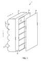
- FIG. 1is a schematic representation of a digitally output lenticular image made using the present invention
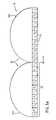
- FIG. 1 ais a schematic end view of a digitally output lenticular image in which an interlaced image is joined to a lenticular lens, and showing correspondence between interlaced image segments of the interlaced image and lenticules of the lenticular lens;
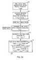
- FIG. 2is a flow chart illustrating a method for determining a lenticular lens for use in digital press printing according to one aspect of the present invention
- FIG. 2 aillustrates a flow chart of additional steps that are taken in determining machine resolution as part of the method of FIG. 2 ;
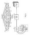
- FIG. 3is a schematic flow chart of a method for systematically selecting the lens for use in producing a digitally output lenticular image according to one aspect of the present invention
- FIG. 4is a schematic illustration of a computerized data field that can be populated to accomplish at least one aspect of the present invention.
- FIG. 5is a schematic graphical representation of the compressing, interlacing and creation of frame files that may be used in at least one aspect of the present invention.
- FIG. 1illustrates a digitally output lenticular image 1 made using the present invention.
- the image 1includes a lenticular lens 10 which has a plurality of equally spaced, parallel lenticular lines 12 and a substantially planar back surface 14 .
- the lenticular lines 12define lenticules 11 through which a viewer can see an interlaced image 16 , which is a composite multidimensional image.
- interlaced image 16is joined to the flat back surface 14 of lenticular lens 10 .
- interlaced image 16is printed directly to the back surface 14 of the lenticular lens 10 , e.g., as taught in U.S. Pat. No. 5,457,515, the disclosure of which is incorporated herein by reference.
- the interlaced image 16can be printed to a substrate 18 (e.g., paper, synthetic paper, plastic, metal, glass, or wood) and the substrate and image subsequently joined (e.g., using an adhesive) to the flat back surface 14 of the lenticular lens 10 .
- a substrate 18e.g., paper, synthetic paper, plastic, metal, glass, or wood
- the substrate and image subsequently joinede.g., using an adhesive
- Lenticular lensestake the form of a transparent plastic sheet or web, and the sheet typically includes an array of identical curved or ribbed surfaces that are formed (e.g., cast, coated, embossed, extruded, or co-extruded) on the front surface of the plastic sheet.
- the back surface of the lensis typically flat.
- Each lenticule or individual lensis typically a section of a long cylinder that focuses on, and extends over, substantially the full length of an underlying image. Other lens shapes or profiles are possible (for instance, pyramidal, trapezoidal, parabolic, elliptical and the like).
- the lenticular lensis generally selected to accommodate both the underlying image and the distance from which the image will ordinarily be viewed (i.e., the viewing distance).
- Lenticular lenses and their technologyare well-known and commercially available. Methods for using lenticular lens technology are described in detail in U.S. Pat. Nos. 5,113,213 and 5,266,995, the disclosures of which are incorporated herein by reference. Lenticular lens technologies are more fully described in U.S. Pat. Nos. 6,424,467 and 5,592, 332 and U.S. Patent Application Publication No. US 2003/0002160 A1, the disclosures of which are incorporated herein by reference.
- a “lenticular image”(e.g., the image 1 of FIG. 1 ) comprises an interlaced image 16 (also called an underlying or precursor image) that has been joined to a lenticular lens 10 .
- the precursor imageis a composite of two or more component images or frames that are themselves preferably of photographic quality.
- the component imagesare selected based upon the desired features of the lenticular or final image.
- the component imagesare then arranged, segmented, interlaced and mapped to create the precursor image so that the precursor image corresponds with the lenticular lens in any convenient manner, e.g., such as those taught in U.S. Pat. Nos.
- the precursor or interlaced imagecan be called a “composite, multidimensional image” as noted above.
- Interlaced imagescan be applied to surfaces of varying shapes, such as shapes including one or more curved regions, as taught in U.S. Pat. No. 6,490,092, the disclosure of which is incorporated herein by reference.
- a primary goal of the method to be describedis to ensure that correspondence between the interlaced image 16 and the lenticular lens 10 is achieved in the digital press environment (i.e., when the interlaced image is digitally printed to the lenticular lens or otherwise joined thereto).
- “correspondence”means that each interlaced segment 17 is covered or substantially covered by one lenticule 11 and that the lenticule and interlaced segment are substantially congruent with one another.
- the interlaced imagei.e., the image comprising the interlaced segments arranged in the desired order
- the lenticular lensi.e., the lenticular image
- the appropriate multidimensional effecte.g., flip, motion, 3D, or a combination thereof
- each interlaced image segmentcan be made coarser (i.e., wider) or finer (i.e., narrower) than the lenticule of the lens which overlays it.
- Correspondencecan be confirmed by viewing the interlaced image through the lenticular lens at a predetermined or desired viewing distance to determine whether the desired illusion of multidimensionality is created.
- FIG. 1 ashows a schematic end view of a digitally output lenticular image in which an interlaced image is joined to a lenticular lens, and further shows correspondence between interlaced image segments of the interlaced image and lenticules of the lenticular lens.
- the entire interlaced segment 56is covered or substantially covered by lenticule 54 a .
- lenticular image 50will provide an illusion of multidimensionality to a viewer with little, if any, distortion. Achieving correspondence in the digital environment results in crisp, clear lenticular imaging, and thus, is paramount to overall commercial value for lenticular product sold.
- FIG. 2is a flow chart illustrating a method, generally referred to by the numeral 60 , for determining a lenticular lens for use in digital press printing according to one aspect of the present invention.
- One digital press suitable for use in the following methodologyis the HP Indigo Press s2000, available from Hewlett-Packard, of Palo Alto, Calif.
- the method 60comprises determining 64 a digital press machine or output resolution d, with the determining step further delineated in FIG. 2 a and associated description below.
- a master interlaced image resolution mis set 66 for a master interlaced image such that the master interlaced image resolution is equal 68 to the machine resolution d.
- the master interlaced image resolutionis re-adjusted such that the equality will exist.
- the number of frames fcan be determined at virtually any point in the process, and can be determined based on a variety of factors (e.g., intended multidimensional effect, complexity of the effect to be illustrated, technical limitations such as computer memory, etc.), however, it is of note that the number of frames f is an integer, and that integer must be identified or determined as part of the selection of the particular lenticular lens to be used.
- the steps of setting the master interlaced image resolution m and the setting of the number of frames f, namely steps 66 and 78 ,are accomplished preferably while creating the master interlaced image 82 , explained further respect to the screen shots of FIG. 3 described below.
- An interlaced imagecan be printed 92 using the digital press, and the actual operating machine resolution d act can be determined 94 therefrom.
- d actcan be determined by end product technical inspection, or by comparison with outputs of known resolution.
- the digital printing presscan be said to be “fingerprinted”, that is, the identification of the machine resolution that accounts for variation from press to press.
- L actd act/f.
- the lens selection processis complete. In most instances this will not be the case.
- the machine resolution d actis tuned to obtain a tuned machine resolution d tuned . Tuning is accomplished by altering, adjusting, repositioning, or reconfiguring (to the extent possible) the mechanical, electromechanical and/or other operational components (e.g., mirrors, prisms, etc.) of the press to print the interlaced image such that it is in correspondence with the lenticular lens.
- L tunedwill typically be coarser or finer than L act previously calculated.
- L tunedis a value that matches a standard commercially available lenticular lens resolution L comm (e.g., 100 lpi, 150, lpi, 200 lpi, etc.).
- L comma standard commercially available lenticular lens resolution
- such commercially available lensestypically vary to some extent from the stated numbers, for example, the “100 lines per inch” or “100 line” lens is actually on the order of about 101.5 lpi.
- a commercially available lenticular lenscan be used in a digital printing press, accounting for actual operating conditions, which can result in digitally imaged lenticular products having the desired number of frames, while providing an interlaced image that is in correspondence with the lenticular lens.
- exemplary lens resolutionscan be in a range of between about 10 and about 250 lines per inch (lpi), although higher lens resolutions are possible and considered within the scope of the present invention.
- exemplary lens resolutionscan be in a range of between about 90 and 110 lpi.
- exemplary lens resolutionscan be in a range of between about 130 and about 160 lpi.
- exemplary lens resolutionscan be in a range of between about 190 and about 210 lpi.
- exemplary lens resolutionscan be about 101.6 lpi, 116.1 lpi, 135.5 lpi, 162.6 lpi, 203.2 lpi, 270.9 lpi, or 406.4 lpi.
- printing 102 of an interlaced imagecan be accomplished. More specifically, an interlaced image is printed 102 at a machine resolution d to the selected lenticular lens having a resolution L can be accomplished, thereby creating a digitally output lenticular image having f frames, where the image and lens are in correspondence.
- FIG. 3is a schematic flow chart of a method for systematically selecting the lens for use in producing a digitally output lenticular image according to one aspect of the present invention.
- a plurality of frame files 110is created and the frame files include each image or frame to be included in the interlaced image.
- layered file 112can be provided from which the plurality of frame files 110 can be created, the layered file and frame files created using commercially available software, such as Adobe® Photoshop®.
- the number of frames fthere is typically a one-to-one correlation between the number of frames f and the number of frame files.
- the number of layers of imaging in the layered filecan vary depending, for example, on the complexity and number of base images to be included in the interlaced image.
- the layered file(s)can take a variety of formats, for example, TIFF, PSD (available from Adobe®), among others, as is desired by the creator.
- the frame file(s)can also take a variety of formats, for example, TIFF, GIF, or JPEG, among others.
- FIG. 4is a schematic illustration of a computerized data field that can be populated to accomplish at least one aspect of the present invention.
- FIG. 5are schematic graphical representations of a frame and a master file that are created as part of at least one aspect of the present invention.
- block area 151is representative of a graphical user interface (GUI) that can be part of a commercial software program (which can be customized if necessary).
- GUIgraphical user interface
- Exemplary data fieldscan include, for example, image width 150 , image height 152 , image bleed 154 , live area for the image 156 .
- “Screening”refers to the process of converting a continuous tone image to a matrix of dots in sizes proportional to the highlights (i.e., the lightest or whitest area of an image) and shadows (i.e., the darkest portions of the image) of the continuous tone image.
- Image screening techniquescan include, for example, half-tone screening and stochastic screening. In conventional half-tone screening, the number of dots per inch remains constant, although the size of the dots can vary in relation to the tonal range density of the pixel depth that they represent. Stochastic or frequency-modulated (FM) screening can create the illusion of tone. Stochastic screening techniques typically yield higher resolutions than are typically obtained in conventional half-tone dot screening. Stochastic screening utilizes finer spots, and results in a higher resolution. In general, stochastic screening is preferable when smaller or finer images are utilized, and when it is desired to illustrate greater detail.
- FMfrequency-modulated
- screeningcan take place prior to interlacing, after interlacing but prior to sending the interlaced image to an output device (preferably a high resolution output device), or after sending the interlaced image to the Raster Image Processor, that is, a “RIP”, (e.g., Adobe® PostScript®) of the output device.
- RIPe.g., Adobe® PostScript®
- the appropriate image resolution corresponding with the lenticular lens resolution or pitchis identified, taking into account generally more than one direction, for example a first direction 164 coinciding with the lenticules of the lens, and a second resolution 166 coinciding with a direction perpendicular to, or across, the lenticules of the lens. These directions are indicated with respect to the lens 10 of FIG. 1 .
- the creation of the master interlaced imageis shown. More specifically, using the data obtained via the fields shown in FIG. 4 , the frame files 168 can either be directly interlaced using the screening methodology of FIG. 4 to create the master interlaced image 170 , or alternatively, each of the frame files 168 can be compressed 172 prior to screening the files and creating the master interlaced image file. Whether screening or interlacing takes place first, with respect to the screening technique or algorithm used, it is preferable to created the master interlaced image such that little, if any, degradation occurs to the master interlaced image. Master interlaced image 170 can be separated and stored in individual color data files correlating with component colors.
- subtractive color scheme CYMKis used, but in an alternative embodiment, additive color scheme such as RGB may be utilized. It is contemplated that other color models, including but not limited to, hexachrome, hi-fi color, extended color gamut (e.g., including light cyan “c” and regular cyan “C”), spot colors, bumps, among others. In this way, the master interlaced image 170 can be screened according to individual colors forming the basis for each individual color data file 174 a–d.
- the file informationcan be sent to a digital printing press 116 , such as the H-P Indigo press s2000, or other suitable digital press.
- a digital printing press 116such as the H-P Indigo press s2000, or other suitable digital press.
- the lenticular lens 118 of known resolution, as determined according to the methodology outlined above in FIGS. 2 and 2 acan be, in one embodiment, utilized as the media or substrate upon which interlaced image (created from the master interlaced file) is digitally printed. More specifically, the lens is positioned to receive the printed image directly on its flat back surface.
- the interlaced imagecan be printed to another substrate (e.g., paper, plastic, metal, glass, or wood) and the substrate with the printed interlaced image thereon subsequently joined (e.g., via an adhesive) to the lenticular lens in a manner that achieves correspondence between the lens and the image.
- a digitally output lenticular image 120which can itself be a finished product, or alternatively, incorporated as a unique or significant feature of a subsequent product, for example, a container (e.g., a cup) 122 , a package 124 , or a label 126 .
- the appropriate lenticular lensis selected to accommodate the image and the predetermined viewing distance.
- a thick, coarse lenticular lensis usually preferred.
- a fine lenticular lensis typically preferred.
- Coarse lenticular lenseshave fewer lenticules per linear inch than fine lenticular lenses.
- Other factors often considered in the choice of a lenticular lensinclude the thickness, flexibility, the viewing distance, the cost of the lens, among others. Increasingly, finer lenticular lenses are becoming more possible and commercially feasible.
- the lens selectedshould be exactly 100 lpi (i.e., 800 dpi/8 frames).
- the actual machine resolutionis determined (“fingerprinted”) to be 812.8 dpi. Therefore, a desired lenticular lens resolution would be 101.6 lpi (i.e., 812.8 dpi/8 frames).
- the commercially available lensis 101.5 lpi for a stated “100 lpi” lenticular lens.
- the s2000 printing press machine resolutionis further tuned downward to an optimal tuned resolution of 812 dpi (101.5 lpi times 8 frames) by internally adjusting one or more physical press characteristics.
- this tuned machine resolutionprinted to this lot of lenticular lens material of a determined pitch, will result in a digitally output lenticular product in which the lens and image are in correspondence.
Landscapes
- Engineering & Computer Science (AREA)
- Physics & Mathematics (AREA)
- General Physics & Mathematics (AREA)
- Multimedia (AREA)
- Signal Processing (AREA)
- Business, Economics & Management (AREA)
- Accounting & Taxation (AREA)
- Marketing (AREA)
- Theoretical Computer Science (AREA)
- Stereoscopic And Panoramic Photography (AREA)
Abstract
Description
L=d/f.
Again, the resolution or pitch is typically identified as lenticules per inch (“lpi”).
Ltheoretical=dmanf/f
Lact=dact/f.
To the extent that Lactis a commercially available lens resolution, the lens selection process is complete. In most instances this will not be the case. To the extent that it differs, it is necessary to tune98 the digital press such that printing in correspondence can occur. More specifically, the machine resolution dactis tuned to obtain a tuned machine resolution dtuned. Tuning is accomplished by altering, adjusting, repositioning, or reconfiguring (to the extent possible) the mechanical, electromechanical and/or other operational components (e.g., mirrors, prisms, etc.) of the press to print the interlaced image such that it is in correspondence with the lenticular lens.
Ltuned=dtuned/f.
In practice, Ltunedwill typically be coarser or finer than Lactpreviously calculated. Ideally, Ltunedis a value that matches a standard commercially available lenticular lens resolution Lcomm(e.g., 100 lpi, 150, lpi, 200 lpi, etc.). In practice, such commercially available lenses typically vary to some extent from the stated numbers, for example, the “100 lines per inch” or “100 line” lens is actually on the order of about 101.5 lpi. Accordingly, the tuning of the digital press preferably results in an equality summarized as:
Ltuned=Lcomm.
In this manner, a commercially available lenticular lens can be used in a digital printing press, accounting for actual operating conditions, which can result in digitally imaged lenticular products having the desired number of frames, while providing an interlaced image that is in correspondence with the lenticular lens.
Claims (20)
Ltuned=dtuned/f.
Lact=dact/f.
Priority Applications (1)
| Application Number | Priority Date | Filing Date | Title |
|---|---|---|---|
| US11/113,662US7153047B2 (en) | 2004-01-09 | 2005-04-25 | Systematic lenticular lens selection in a digital printing environment |
Applications Claiming Priority (2)
| Application Number | Priority Date | Filing Date | Title |
|---|---|---|---|
| US10/754,243US7083340B2 (en) | 2004-01-09 | 2004-01-09 | Systematic lenticular lens selection in a digital printing environment |
| US11/113,662US7153047B2 (en) | 2004-01-09 | 2005-04-25 | Systematic lenticular lens selection in a digital printing environment |
Related Parent Applications (1)
| Application Number | Title | Priority Date | Filing Date |
|---|---|---|---|
| US10/754,243ContinuationUS7083340B2 (en) | 2004-01-09 | 2004-01-09 | Systematic lenticular lens selection in a digital printing environment |
Publications (2)
| Publication Number | Publication Date |
|---|---|
| US20050191104A1 US20050191104A1 (en) | 2005-09-01 |
| US7153047B2true US7153047B2 (en) | 2006-12-26 |
Family
ID=34739343
Family Applications (2)
| Application Number | Title | Priority Date | Filing Date |
|---|---|---|---|
| US10/754,243Expired - LifetimeUS7083340B2 (en) | 2004-01-09 | 2004-01-09 | Systematic lenticular lens selection in a digital printing environment |
| US11/113,662Expired - LifetimeUS7153047B2 (en) | 2004-01-09 | 2005-04-25 | Systematic lenticular lens selection in a digital printing environment |
Family Applications Before (1)
| Application Number | Title | Priority Date | Filing Date |
|---|---|---|---|
| US10/754,243Expired - LifetimeUS7083340B2 (en) | 2004-01-09 | 2004-01-09 | Systematic lenticular lens selection in a digital printing environment |
Country Status (2)
| Country | Link |
|---|---|
| US (2) | US7083340B2 (en) |
| WO (1) | WO2005071938A1 (en) |
Cited By (7)
| Publication number | Priority date | Publication date | Assignee | Title |
|---|---|---|---|---|
| US20040135882A1 (en)* | 2003-01-15 | 2004-07-15 | Chien-Lin Lien | Method to fast search printing frequency to present a 3D image |
| US7359120B1 (en) | 2006-11-10 | 2008-04-15 | Genie Lens Technologies, Llc | Manufacture of display devices with ultrathin lens arrays for viewing interlaced images |
| US7480100B1 (en) | 2007-10-15 | 2009-01-20 | Genie Lens Technologies, Llc | Lenticular devices using sets of lenses to display paired sets of interlaces of images |
| USD735400S1 (en)* | 2013-02-09 | 2015-07-28 | SVV Technology Innovations, Inc | Optical lens array lightguide plate |
| US20150301234A1 (en)* | 2012-04-25 | 2015-10-22 | Humaneyes Technologies Ltd. | Methods and systems of generating a lenticular article using a printing blanket |
| US10065441B2 (en) | 2015-09-01 | 2018-09-04 | Digimarc Corporation | Counterfeiting detection using machine readable indicia |
| US12181690B2 (en) | 2022-07-06 | 2024-12-31 | Lumenco, Llc | Micro-optic anticounterfeiting elements for currency and other items using virtual lens systems |
Families Citing this family (9)
| Publication number | Priority date | Publication date | Assignee | Title |
|---|---|---|---|---|
| US7576918B2 (en)* | 2004-07-20 | 2009-08-18 | Pixalen, Llc | Matrical imaging method and apparatus |
| US8474874B2 (en)* | 2006-10-02 | 2013-07-02 | Travel Tags, Inc. | Layered image display sheet |
| EP2074481A4 (en)* | 2006-10-02 | 2015-05-06 | Travel Tags Inc | Layered image display applications and methods |
| WO2010033836A2 (en) | 2008-09-18 | 2010-03-25 | Taylor Corporation | Thin film high definition dimensional image display device and methods of making same |
| US8964297B2 (en) | 2008-09-18 | 2015-02-24 | Travel Tags, Inc. | Thin film high definition dimensional image display device and methods of making same |
| US8136938B2 (en)* | 2009-05-19 | 2012-03-20 | William Karszes | System and method for printing on lenticular sheets |
| WO2011016037A1 (en)* | 2009-08-03 | 2011-02-10 | Humaneyes Technologies Ltd. | Method and system of displaying prints of reconstructed 3d images |
| BR112012017367A2 (en) | 2010-01-14 | 2017-06-13 | Humaneyes Tech Ltd | method and system for adjusting depth values of objects on a three dimensional screen (3d) |
| CN108136795B (en)* | 2015-08-20 | 2019-12-20 | 惠普深蓝有限责任公司 | Printing facets |
Citations (37)
| Publication number | Priority date | Publication date | Assignee | Title |
|---|---|---|---|---|
| US5113213A (en) | 1989-01-13 | 1992-05-12 | Sandor Ellen R | Computer-generated autostereography method and apparatus |
| US5266995A (en) | 1992-08-12 | 1993-11-30 | Quad/Tech, Inc. | Method for forming a graphic image web |
| US5278608A (en) | 1992-05-19 | 1994-01-11 | Eastman Kodak Company | Electronically printed depth photography system with improved viewing range |
| US5436738A (en) | 1992-01-22 | 1995-07-25 | Eastman Kodak Company | Three dimensional thermal internegative photographic printing apparatus and method |
| US5457515A (en) | 1993-05-10 | 1995-10-10 | Quad/Tech, Inc. | Method for forming a graphic image web |
| US5488451A (en) | 1994-05-03 | 1996-01-30 | National Graphics, Inc. | Method of producing multidimensional lithographic separations free of moire interference |
| US5543964A (en)* | 1993-12-28 | 1996-08-06 | Eastman Kodak Company | Depth image apparatus and method with angularly changing display information |
| US5581402A (en)* | 1993-11-22 | 1996-12-03 | Eastman Kodak Company | Method for producing an improved stereoscopic picture and stereoscopic picture obtained according to this method |
| US5592332A (en) | 1992-12-25 | 1997-01-07 | Dai Nippon Printing Co., Ltd. | Renticular lens, surface light source, and liquid crystal display apparatus |
| US5633719A (en)* | 1994-10-28 | 1997-05-27 | Eastman Kodak Company | Method and apparatus for aligning a lenticular overlay with a lenticular print |
| US5642226A (en)* | 1995-01-18 | 1997-06-24 | Rosenthal; Bruce A. | Lenticular optical system |
| US5847808A (en) | 1996-01-29 | 1998-12-08 | National Graphics, Inc. | Method of producing a multidimensional composite image |
| US5896230A (en) | 1994-05-03 | 1999-04-20 | National Graphics, Inc. | Lenticular lens with multidimensional display having special effects layer |
| US5924870A (en)* | 1996-12-09 | 1999-07-20 | Digillax Systems | Lenticular image and method |
| EP0953935A2 (en) | 1998-04-22 | 1999-11-03 | Eastman Kodak Company | An electronic motion image capture, display and print system for use in a theme park |
| US6163406A (en)* | 1998-11-19 | 2000-12-19 | Eastman Kodak Company | Lenticular image bearing member with variable line spacing to improve image quality |
| US6177217B1 (en) | 1999-07-23 | 2001-01-23 | Eastman Kodak Company | Method and apparatus for precise positioning of arrays with periodic structures |
| US6198544B1 (en) | 1998-04-08 | 2001-03-06 | Eastman Kodak Company | Method and system for capturing images from a video tape for the purpose of creating a motion card |
| US6249384B1 (en)* | 1999-06-29 | 2001-06-19 | Eastman Kodak Company | Detection and correction of skew between a writing laser beam and lenticules in lenticular material |
| US6324545B1 (en)* | 1997-10-15 | 2001-11-27 | Colordesk Ltd. | Personalized photo album |
| US6329987B1 (en)* | 1996-12-09 | 2001-12-11 | Phil Gottfried | Lenticular image and method |
| US6373637B1 (en) | 2000-09-13 | 2002-04-16 | Eastman Kodak Company | Diagonal lenticular image system |
| US20020075566A1 (en) | 2000-12-18 | 2002-06-20 | Tutt Lee W. | 3D or multiview light emitting display |
| US6424467B1 (en) | 2000-09-05 | 2002-07-23 | National Graphics, Inc. | High definition lenticular lens |
| US20020167679A1 (en) | 2001-02-06 | 2002-11-14 | Nims Jerry C. | Method for scaling and interlacing multidimensional and motion images |
| US6490092B1 (en) | 2000-03-27 | 2002-12-03 | National Graphics, Inc. | Multidimensional imaging on a curved surface using lenticular lenses |
| US20020198724A1 (en) | 2001-06-20 | 2002-12-26 | Paul Peterson | Methods and apparatus for producing a lenticular novelty item interactively via the internet |
| US20030002160A1 (en) | 2000-12-29 | 2003-01-02 | Web Communications Group, Inc. | Lenticular lens array and tool for making a lenticular lens array |
| US20030016370A1 (en) | 2001-07-13 | 2003-01-23 | Goggins Timothy P. | Corresponding lenticular imaging |
| US6549295B1 (en)* | 1997-12-15 | 2003-04-15 | Insight, Inc. | Method for making products having merged images |
| US20030128865A1 (en) | 2001-12-13 | 2003-07-10 | White Ian H. | Method of producing maps and other objects configured for presentation of spatially-related layers of data |
| US20030169468A1 (en) | 2000-08-21 | 2003-09-11 | Irina Menz | Security system, particularly for valuable documents |
| US20030183695A1 (en) | 2001-12-18 | 2003-10-02 | Brian Labrec | Multiple image security features for identification documents and methods of making same |
| US6741395B1 (en)* | 2001-06-08 | 2004-05-25 | Lenticlear Lenticular Lens, Inc. | Elliptically-shaped tool |
| US20040157195A1 (en) | 2003-02-12 | 2004-08-12 | Roger Andresen | Methods and apparatus for facilitating conceptual development |
| US6781761B2 (en) | 2002-08-29 | 2004-08-24 | Mark A. Raymond | Lenticular lens system and method for use in producing images with clear-walled containers |
| US7079706B2 (en)* | 2001-06-20 | 2006-07-18 | Paul Peterson | Methods and apparatus for generating a multiple composite image |
- 2004
- 2004-01-09USUS10/754,243patent/US7083340B2/ennot_activeExpired - Lifetime
- 2004-12-31WOPCT/US2004/043898patent/WO2005071938A1/enactiveApplication Filing
- 2005
- 2005-04-25USUS11/113,662patent/US7153047B2/ennot_activeExpired - Lifetime
Patent Citations (41)
| Publication number | Priority date | Publication date | Assignee | Title |
|---|---|---|---|---|
| US5113213A (en) | 1989-01-13 | 1992-05-12 | Sandor Ellen R | Computer-generated autostereography method and apparatus |
| US5436738A (en) | 1992-01-22 | 1995-07-25 | Eastman Kodak Company | Three dimensional thermal internegative photographic printing apparatus and method |
| US5278608A (en) | 1992-05-19 | 1994-01-11 | Eastman Kodak Company | Electronically printed depth photography system with improved viewing range |
| US5266995A (en) | 1992-08-12 | 1993-11-30 | Quad/Tech, Inc. | Method for forming a graphic image web |
| US5592332A (en) | 1992-12-25 | 1997-01-07 | Dai Nippon Printing Co., Ltd. | Renticular lens, surface light source, and liquid crystal display apparatus |
| US5457515A (en) | 1993-05-10 | 1995-10-10 | Quad/Tech, Inc. | Method for forming a graphic image web |
| US5581402A (en)* | 1993-11-22 | 1996-12-03 | Eastman Kodak Company | Method for producing an improved stereoscopic picture and stereoscopic picture obtained according to this method |
| US5543964A (en)* | 1993-12-28 | 1996-08-06 | Eastman Kodak Company | Depth image apparatus and method with angularly changing display information |
| US5488451A (en) | 1994-05-03 | 1996-01-30 | National Graphics, Inc. | Method of producing multidimensional lithographic separations free of moire interference |
| US5617178A (en) | 1994-05-03 | 1997-04-01 | National Graphics, Inc. | Method of producing multidimensional lithographic separations free of moire interference |
| US5896230A (en) | 1994-05-03 | 1999-04-20 | National Graphics, Inc. | Lenticular lens with multidimensional display having special effects layer |
| US5633719A (en)* | 1994-10-28 | 1997-05-27 | Eastman Kodak Company | Method and apparatus for aligning a lenticular overlay with a lenticular print |
| US5642226A (en)* | 1995-01-18 | 1997-06-24 | Rosenthal; Bruce A. | Lenticular optical system |
| US5847808A (en) | 1996-01-29 | 1998-12-08 | National Graphics, Inc. | Method of producing a multidimensional composite image |
| US5924870A (en)* | 1996-12-09 | 1999-07-20 | Digillax Systems | Lenticular image and method |
| US6329987B1 (en)* | 1996-12-09 | 2001-12-11 | Phil Gottfried | Lenticular image and method |
| US6324545B1 (en)* | 1997-10-15 | 2001-11-27 | Colordesk Ltd. | Personalized photo album |
| US6549295B1 (en)* | 1997-12-15 | 2003-04-15 | Insight, Inc. | Method for making products having merged images |
| US6198544B1 (en) | 1998-04-08 | 2001-03-06 | Eastman Kodak Company | Method and system for capturing images from a video tape for the purpose of creating a motion card |
| EP0953935A2 (en) | 1998-04-22 | 1999-11-03 | Eastman Kodak Company | An electronic motion image capture, display and print system for use in a theme park |
| US6163406A (en)* | 1998-11-19 | 2000-12-19 | Eastman Kodak Company | Lenticular image bearing member with variable line spacing to improve image quality |
| US6249384B1 (en)* | 1999-06-29 | 2001-06-19 | Eastman Kodak Company | Detection and correction of skew between a writing laser beam and lenticules in lenticular material |
| US6177217B1 (en) | 1999-07-23 | 2001-01-23 | Eastman Kodak Company | Method and apparatus for precise positioning of arrays with periodic structures |
| US6490092B1 (en) | 2000-03-27 | 2002-12-03 | National Graphics, Inc. | Multidimensional imaging on a curved surface using lenticular lenses |
| US20030169468A1 (en) | 2000-08-21 | 2003-09-11 | Irina Menz | Security system, particularly for valuable documents |
| US6424467B1 (en) | 2000-09-05 | 2002-07-23 | National Graphics, Inc. | High definition lenticular lens |
| US6373637B1 (en) | 2000-09-13 | 2002-04-16 | Eastman Kodak Company | Diagonal lenticular image system |
| US20020075566A1 (en) | 2000-12-18 | 2002-06-20 | Tutt Lee W. | 3D or multiview light emitting display |
| US20030002160A1 (en) | 2000-12-29 | 2003-01-02 | Web Communications Group, Inc. | Lenticular lens array and tool for making a lenticular lens array |
| US6795250B2 (en)* | 2000-12-29 | 2004-09-21 | Lenticlear Lenticular Lens, Inc. | Lenticular lens array |
| US20020167679A1 (en) | 2001-02-06 | 2002-11-14 | Nims Jerry C. | Method for scaling and interlacing multidimensional and motion images |
| US7019865B2 (en)* | 2001-02-06 | 2006-03-28 | Orasee Corp. | Method for scaling and interlacing multidimensional and motion images |
| US6741395B1 (en)* | 2001-06-08 | 2004-05-25 | Lenticlear Lenticular Lens, Inc. | Elliptically-shaped tool |
| US6833961B2 (en)* | 2001-06-08 | 2004-12-21 | Web Communications Group, Inc. | Pseudo elliptically-shaped tool |
| US20020198724A1 (en) | 2001-06-20 | 2002-12-26 | Paul Peterson | Methods and apparatus for producing a lenticular novelty item interactively via the internet |
| US7079706B2 (en)* | 2001-06-20 | 2006-07-18 | Paul Peterson | Methods and apparatus for generating a multiple composite image |
| US20030016370A1 (en) | 2001-07-13 | 2003-01-23 | Goggins Timothy P. | Corresponding lenticular imaging |
| US20030128865A1 (en) | 2001-12-13 | 2003-07-10 | White Ian H. | Method of producing maps and other objects configured for presentation of spatially-related layers of data |
| US20030183695A1 (en) | 2001-12-18 | 2003-10-02 | Brian Labrec | Multiple image security features for identification documents and methods of making same |
| US6781761B2 (en) | 2002-08-29 | 2004-08-24 | Mark A. Raymond | Lenticular lens system and method for use in producing images with clear-walled containers |
| US20040157195A1 (en) | 2003-02-12 | 2004-08-12 | Roger Andresen | Methods and apparatus for facilitating conceptual development |
Cited By (14)
| Publication number | Priority date | Publication date | Assignee | Title |
|---|---|---|---|---|
| US7372458B2 (en)* | 2003-01-15 | 2008-05-13 | Chien-Lin Lien | Method to fast search printing frequency to present a 3D image |
| US20040135882A1 (en)* | 2003-01-15 | 2004-07-15 | Chien-Lin Lien | Method to fast search printing frequency to present a 3D image |
| US7359120B1 (en) | 2006-11-10 | 2008-04-15 | Genie Lens Technologies, Llc | Manufacture of display devices with ultrathin lens arrays for viewing interlaced images |
| US20080150174A1 (en)* | 2006-11-10 | 2008-06-26 | Genie Lens Technologies, Llc | Manufacture of display devices with ultrathin lins arrays for viewing interlaced images |
| US7731813B2 (en) | 2006-11-10 | 2010-06-08 | Genie Lens Technologies, Llc | Manufacture of display devices with ultrathin lens arrays for viewing interlaced images |
| US7480100B1 (en) | 2007-10-15 | 2009-01-20 | Genie Lens Technologies, Llc | Lenticular devices using sets of lenses to display paired sets of interlaces of images |
| US9641702B2 (en)* | 2012-04-25 | 2017-05-02 | Humaneyes Technologies Ltd. | Methods and systems of generating a lenticular article using a printing blanket |
| US20150301234A1 (en)* | 2012-04-25 | 2015-10-22 | Humaneyes Technologies Ltd. | Methods and systems of generating a lenticular article using a printing blanket |
| USD735400S1 (en)* | 2013-02-09 | 2015-07-28 | SVV Technology Innovations, Inc | Optical lens array lightguide plate |
| US10065441B2 (en) | 2015-09-01 | 2018-09-04 | Digimarc Corporation | Counterfeiting detection using machine readable indicia |
| US10350926B2 (en) | 2015-09-01 | 2019-07-16 | Digimarc Corporation | Counterfeit detection using machine readable indicia |
| US10987960B2 (en) | 2015-09-01 | 2021-04-27 | Digimarc Corporation | Counterfeit detection using machine readable indicia |
| US11560005B2 (en) | 2015-09-01 | 2023-01-24 | Digimarc Corporation | Counterfeit detection using machine readable indicia |
| US12181690B2 (en) | 2022-07-06 | 2024-12-31 | Lumenco, Llc | Micro-optic anticounterfeiting elements for currency and other items using virtual lens systems |
Also Published As
| Publication number | Publication date |
|---|---|
| US20050191104A1 (en) | 2005-09-01 |
| US20050152729A1 (en) | 2005-07-14 |
| WO2005071938A1 (en) | 2005-08-04 |
| US7083340B2 (en) | 2006-08-01 |
Similar Documents
| Publication | Publication Date | Title |
|---|---|---|
| US6995913B2 (en) | Digitally imaged lenticular products incorporating customized elements | |
| US7153047B2 (en) | Systematic lenticular lens selection in a digital printing environment | |
| US7239420B2 (en) | Corresponding lenticular imaging | |
| US5847808A (en) | Method of producing a multidimensional composite image | |
| EP0772797B1 (en) | Method of producing multidimensional lithographic separations free of moire interference | |
| EP3251346B1 (en) | Digital multi-dimensional image photon platform system and methods of use | |
| US20050152040A1 (en) | Digitally imaged lenticular products incorporating a special effect feature | |
| US5896230A (en) | Lenticular lens with multidimensional display having special effects layer | |
| US8576450B2 (en) | Replacing a defective colorant | |
| US7019865B2 (en) | Method for scaling and interlacing multidimensional and motion images | |
| US5920682A (en) | Multiple layer cluster dither matrix for reducing artifacts in printed images | |
| US6674546B1 (en) | Image processing method according to sort of image and image processing apparatus | |
| US8149464B2 (en) | Clustered dot-screen design method, a device to perform the clustered dot-screen design method based on human vision and printer model characteristics, and an image-forming apparatus to output binary images on a designed screen | |
| WO2018071638A1 (en) | Lens-based security dedicated to individual colors for currency and brand authentication | |
| JPH0961950A (en) | 3D image printed matter | |
| US20050271292A1 (en) | Lenticular imaging file manipulation method | |
| US9100623B2 (en) | Image processing device and method for adding textures to background and to an object | |
| JP4138576B2 (en) | Method and system for processing multicolor images | |
| JP2006005926A (en) | Method of generating dither mask | |
| JP6268795B2 (en) | Image generation program and printing apparatus | |
| EP1608146B1 (en) | Method for generating a dither mask | |
| HK1239999B (en) | Digital multi-dimensional image photon platform system and methods of use | |
| HK1239999A1 (en) | Digital multi-dimensional image photon platform system and methods of use |
Legal Events
| Date | Code | Title | Description |
|---|---|---|---|
| STCF | Information on status: patent grant | Free format text:PATENTED CASE | |
| AS | Assignment | Owner name:GOGGINS, TIMOTHY, WISCONSIN Free format text:TERMINATION OF INVENTION ASSIGNMENT;ASSIGNOR:NATIIONAL GRAPHICS, INC.;REEL/FRAME:021398/0637 Effective date:20041123 | |
| AS | Assignment | Owner name:GOGGINS, TIMOTHY, WISCONSIN Free format text:CORRECTIVE ASSIGNMENT TO CORRECT THE TYPO IN ASSIGNOR NAME TO READ NATIONAL GRAPHICS, INC., AND REMOVE INCORRECT SERIAL NO. 09/894,764 (PATENT NO. 6,947,080) PREVIOUSLY RECORDED ON REEL 021398 FRAME 0637. ASSIGNOR(S) HEREBY CONFIRMS THE ASSIGNMENT.;ASSIGNOR:NATIONAL GRAPHICS, INC.;REEL/FRAME:021511/0539 Effective date:20041123 Owner name:GOGGINS, TIMOTHY, WISCONSIN Free format text:CORRECTIVE ASSIGNMENT TO CORRECT THE TYPO IN ASSIGNOR NAME TO READ NATIONAL GRAPHICS, INC., AND REMOVE INCORRECT SERIAL NO. 09/894,764 (PATENT NO. 6,947,080) PREVIOUSLY RECORDED ON REEL 021398 FRAME 0637;ASSIGNOR:NATIONAL GRAPHICS, INC.;REEL/FRAME:021511/0539 Effective date:20041123 | |
| AS | Assignment | Owner name:GOGGINS, TIMOTHY, WISCONSIN Free format text:COMPLETED TERMINATION OF INVENTION ASSIGNMENT AND DEVELOPMENT AGREEMENT EXHIBIT;ASSIGNOR:NATIONAL GRAPHICS, INC.;REEL/FRAME:022980/0499 Effective date:20041123 | |
| FEPP | Fee payment procedure | Free format text:PAT HOLDER CLAIMS SMALL ENTITY STATUS, ENTITY STATUS SET TO SMALL (ORIGINAL EVENT CODE: LTOS); ENTITY STATUS OF PATENT OWNER: SMALL ENTITY | |
| FPAY | Fee payment | Year of fee payment:4 | |
| AS | Assignment | Owner name:NATIONAL GRAPHICS, INC., WISCONSIN Free format text:REAFFIRMATION OF OWNERSHIP PER COURT DOCUMENTS;ASSIGNOR:GOGGINS, TIMOTHY P;REEL/FRAME:025845/0978 Effective date:20091123 | |
| AS | Assignment | Owner name:SPARTECH POLYCOM (TEXAS), INC. D/B/A POLYONE PACKA Free format text:SECURITY AGREEMENT;ASSIGNOR:NATIONAL GRAPHICS, INC.;REEL/FRAME:031188/0385 Effective date:20130819 | |
| AS | Assignment | Owner name:POLYONE DESIGNED STRUCTURES AND SOLUTIONS LLC, OHI Free format text:SECURITY INTEREST;ASSIGNOR:NATIONAL GRAPHICS, INC.;REEL/FRAME:032694/0616 Effective date:20140410 | |
| FPAY | Fee payment | Year of fee payment:8 | |
| AS | Assignment | Owner name:NATIONAL GRAPHICS, INC., WISCONSIN Free format text:RELEASE BY SECURED PARTY;ASSIGNOR:POLYONE DESIGNATED STRUCTURES AND SOLUTIONS, LLC;REEL/FRAME:038197/0213 Effective date:20160404 | |
| AS | Assignment | Owner name:NATIONAL GRAPHICS, INC., WISCONSIN Free format text:RELEASE BY SECURED PARTY;ASSIGNOR:POLYONE DESIGNATED STRUCTURES AND SOLUTIONS, LLC;REEL/FRAME:038242/0198 Effective date:20160404 | |
| AS | Assignment | Owner name:DYNAMIC DRINKWARE LLC, WISCONSIN Free format text:ASSIGNMENT OF ASSIGNORS INTEREST;ASSIGNOR:NATIONAL GRAPHICS, INC.;REEL/FRAME:039247/0047 Effective date:20160401 | |
| MAFP | Maintenance fee payment | Free format text:PAYMENT OF MAINTENANCE FEE, 12TH YR, SMALL ENTITY (ORIGINAL EVENT CODE: M2553) Year of fee payment:12 | |
| AS | Assignment | Owner name:PACUR, LLC, WISCONSIN Free format text:ASSIGNMENT OF ASSIGNORS INTEREST;ASSIGNOR:DYNAMIC DRINKWARE, LLC;REEL/FRAME:052838/0988 Effective date:20200604 |