US7152456B2 - Automated robotic measuring system - Google Patents
Automated robotic measuring systemDownload PDFInfo
- Publication number
- US7152456B2 US7152456B2US10/758,697US75869704AUS7152456B2US 7152456 B2US7152456 B2US 7152456B2US 75869704 AUS75869704 AUS 75869704AUS 7152456 B2US7152456 B2US 7152456B2
- Authority
- US
- United States
- Prior art keywords
- articulated
- arm
- positioning
- measuring arm
- positioning system
- Prior art date
- Legal status (The legal status is an assumption and is not a legal conclusion. Google has not performed a legal analysis and makes no representation as to the accuracy of the status listed.)
- Expired - Lifetime
Links
Images


Classifications
- G—PHYSICS
- G01—MEASURING; TESTING
- G01B—MEASURING LENGTH, THICKNESS OR SIMILAR LINEAR DIMENSIONS; MEASURING ANGLES; MEASURING AREAS; MEASURING IRREGULARITIES OF SURFACES OR CONTOURS
- G01B5/00—Measuring arrangements characterised by the use of mechanical techniques
- G01B5/004—Measuring arrangements characterised by the use of mechanical techniques for measuring coordinates of points
- Y—GENERAL TAGGING OF NEW TECHNOLOGICAL DEVELOPMENTS; GENERAL TAGGING OF CROSS-SECTIONAL TECHNOLOGIES SPANNING OVER SEVERAL SECTIONS OF THE IPC; TECHNICAL SUBJECTS COVERED BY FORMER USPC CROSS-REFERENCE ART COLLECTIONS [XRACs] AND DIGESTS
- Y10—TECHNICAL SUBJECTS COVERED BY FORMER USPC
- Y10T—TECHNICAL SUBJECTS COVERED BY FORMER US CLASSIFICATION
- Y10T74/00—Machine element or mechanism
- Y10T74/20—Control lever and linkage systems
- Y10T74/20207—Multiple controlling elements for single controlled element
- Y10T74/20305—Robotic arm
- Y10T74/20329—Joint between elements
Definitions
- the present teachingsgenerally relate to rectilinear measuring systems and articulated arm coordinate measuring machines and more particularly to a system for automated measuring arm positioning.
- Rectilinear measuring systemsalso referred to as coordinate measuring machines (CMM's) and articulated arm measuring machines including portable coordinate measuring machines (PCMM's) have been described for generating geometry information from various objects and areas.
- CCM'scoordinate measuring machines
- PCMM'sportable coordinate measuring machines
- CMM'scoordinate measuring machines
- these instrumentscapture the structural characteristics of an object for use in electronic rendering and duplication.
- a conventional apparatus used for coordinate data acquisitioncomprises a support and a moveable measuring arm made up of hinged segments to which a contact-sensitive probe or remote scanning device is attached.
- Geometry information or three-dimensional coordinate data characterizing the shape, features, and size of the objectmay be acquired by tracing or scanning along the object's surface and contours.
- Probe or scanning device movementis typically tracked relative to a reference coordinate system resulting in a collection of data points and information that may be used to develop an accurate electronic rendering of the object.
- the acquired geometry informationis processed by a computer capable of making use of the information to model the surface contours and dimensions of the object.
- the present teachingsrelate to an articulated arm coordinate measuring machine (CMM) having improved tolerance to external physical perturbations.
- CMMcomprises a measuring arm having a coordinate acquisition probe or remote scanning device attached thereto coupled with a powered exoskeletal frame and other components that provide improved vibration and temperature damping characteristics over conventional designs.
- the exoskeletal frame and other components that make up the apparatus for actuator assisted movement of the measuring armmay be adapted for use with existing CMM's thus providing a means to improve the performance of these devices.
- the present teachingsdescribe a configuration for a CMM capable of robotic or motor-assisted movement.
- Actuatorsprovide movement for the measuring arm and may be remotely located at various positions on the measuring arm or separately contained in an external housing to improve stability and coordinate acquisition accuracy.
- the actuatorsremotely drive selected hinge, joint, or measuring armature segments using flexible drive cables which enable multi-axis control and movement of the measuring arm, probe, and/or remote scanning device.
- the present teachingsdescribe a robotically-assisted PCMM that may be operated in a power-assisted manual mode.
- the PCMMis capable of withstanding various vibrations and jarring effects through a vibration damping system between the exoskeletal frame and the measuring arm.
- the PCMMmay be configured to recognize when the measuring arm has become mispositioned and may compensate or realign the measuring arm as desired or instructed.
- the present teachingsdescribe a system for calibrating and training a CMM. Calibration may be performed in a substantially automated manner or alternatively an operator-assisted mode may be used. Once a training parameter set has been developed, this information may be applied to other similar CMMs improving the efficiency of device calibration or substantially eliminating this process altogether.
- the present teachingsdescribe a process for determining the position of the measuring arm using encoders which detect the angular position of both the measuring arm and the exoskeletal frame relative to one another.
- Actuator positioning information stored in a lookup table in combination with encoder determined angular valuesprovides a highly accurate database for aligning the measuring arm and providing feedback to correct/adjust the position of the measuring arm.
- the inventioncomprises a positioning system for accurately orienting an articulated arm.
- the systemfurther comprises an articulated supporting arm comprising a plurality of jointedly interconnected support arm segments moveable about a plurality of axes; a plurality of compliant members positioned on said supporting arm; and an articulated measuring arm comprising a plurality of jointedly interconnected measuring arm segments capable of a plurality of degrees of freedom of movement and supported by said compliant members wherein said compliant members provide a yielding characteristic between the articulated supporting arm and the articulated measuring arm.
- the inventioncomprises an accurate positioning system.
- the systemfurther comprises an articulated supporting arm comprising a plurality of jointedly interconnected support arm segments moveable about a plurality of axes; a plurality of compliant members positioned about said supporting arm; an articulated measuring arm comprising a plurality of jointedly interconnected measuring arm segments capable of a plurality of degrees of freedom of movement and supported by said compliant members wherein said compliant members provide a yielding characteristic between the articulated supporting arm and the articulated measuring arm.
- a controlleris further configured to direct positioning of the articulated supporting arm and a datastore containing information that is accessible by the controller is used to resolve the alignment of the articulated supporting arm with respect to the articulated measuring arm.
- the inventioncomprises a method for positioning an articulated measuring arm.
- the positioning methodfurther comprises supporting said arm at a plurality of locations with compliant members to reduce mechanical stress on said arm.
- the inventioncomprises a method for damping external perturbations encountered by an articulated measuring arm.
- the methodfurther comprises supporting said arm at a plurality of locations with compliant members that position at least a portion of the articulated measuring arm within an exoskeletal structure.
- the inventioncomprises a method for directing positioning of an articulated positioning arm and an interconnected articulated measuring arm.
- the methodfurther comprises the steps of: (a) identifying a plurality of instructions used by a controller to direct positioning of the articulated positioning arm in a plurality of orientations; (b) measuring the resulting position of the articulated measuring arm arising from each controller instruction; and (c) associating and storing the instructions and the resulting positionings thereafter to be used by the controller to effectuate a selected positioning.
- the inventioncomprises a positioning system for directing positioning of an articulated arm.
- the systemfurther comprising: an articulated arm comprising jointedly interconnected arm segments moveable about at least one degree of freedom; an articulation member configured to position the jointedly interconnected arm segments; and a remotely located actuator interconnected to the articulation member by a drive member, wherein the actuator generates a motive force transmitted through the drive member to the articulation member directing positioning by the articulation member and effectuating movement of the positioning arm.
- FIG. 1illustrates one embodiment of an automated robotic measuring system according to the present teachings.
- FIG. 2Aillustrates an exemplary articulated measuring arm and ranges of movement imparted by various articulation members.
- FIG. 2Billustrates an exploded view of a portion of the measuring arm shown in FIG. 2A exemplifying the interconnection between inner and outer members.
- FIG. 2Cillustrates an exemplary encoder arrangement along the measuring arm.
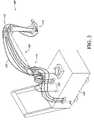
- FIG. 3illustrates an exemplary actuator configuration for the automated robotic measuring system.
- FIG. 4illustrates another exemplary actuator configuration for the automated robotic measuring system.
- FIG. 5illustrates a block diagram of the components that provide for feedback and control of the automated robotic measuring system.
- FIG. 6illustrates a flowchart for developing a training parameter set for the automated robotic measuring system.
- FIG. 7illustrates an exemplary lookup table used in conjunction with the automated robotic measuring system.
- While various embodiments of the present teachingsare directed towards an automated robotic measuring system or a motor-assisted coordinate measuring machine; one skilled in the technology will appreciate that the systems and methods described herein may be adapted for use with other types of CMMs and PCMMs.
- the vibration damping and thermal compensation featuresmay be adapted for use with conventional designs to improve their resistance to external perturbations.
- the motor-assisted control and movement characteristics of the present teachingsmay be adapted for use with conventional CMM designs to improve the precision and accuracy of these assemblies.
- the motor-assisted designs illustrated in the FIGS. 1 , 3 , and 4are but various representative embodiments of the scope of the present teachings. It will be appreciated that the invention is not limited exclusively to these embodiments, but rather includes additional implementations as well.
- the automated robotic measuring systemcomprises an “arm within an arm” or dual-positioning member design wherein a measuring arm to which a coordinate acquisition member or probe is attached is adapted for use with a positioning member comprising a shell or arm alignment structure.
- the positioning memberforms an exoskeletal structure which at least partially encloses portions of the measuring arm, although the positioning member is not necessarily limited to this particular configuration.
- the measuring arm and positioning memberare interconnected by way of deformable compliant members or support webs which align the measuring arm and positioning members with respect to one another and aid in detecting loads imparted upon either component.
- detected loadsserve as a basis for providing power-assisted movement of the arm members in various controllable manners.
- the exoskeletal or alignment structurefurther serves as a physical perturbation damping means which contributes to improved stability and accuracy of the measuring arm to which the coordinate acquisition or probe member is attached thereby improving the performance of the instrument.
- the automated robotic measuring system of the present teachingsdiffers from traditional or conventional designs in that the first measuring arm member is driven by the positioning member using an actuator and encoder-based control system instead of a robotic system employing a singular arm member designed for both movement and measurement.
- This difference in designis significant as it increases measuring arm stability, allows for finer and more precise movement, and contributes to improved measurement accuracy.
- FIG. 1illustrates an exemplary automated robotic measuring system 100 according to the present teachings.
- the system 100comprises a coordinate measuring machine having an articulated measuring arm 105 to which a coordinate acquisition member 110 is mounted.
- the measuring arm 105is used to align the coordinate acquisition member 110 in various spatial orientations through a plurality of articulation members 115 each of which impart one or more rotational or angular degrees of freedom to the measuring arm 105 to thereby allow fine positioning of the coordinate acquisition member 110 in three dimensional space.
- the coordinate acquisition member 110comprises a contact sensitive member or probe configured to engage the surfaces of a selected object and generate coordinate data on the basis of probe contact as directed through the measuring arm 105 .
- the coordinate acquisition member 110may comprise a remote scanning and detection component that does not necessarily require direct contact with the selected object to acquire geometry data.
- a laser coordinate detection devicee.g. laser camera
- acquisition of coordinate datais generally described in the context of the laser coordinate detection device; however it will be appreciated that the system and methods described herein may be readily adapted to numerous different configurations to achieve other manners of coordinate data acquisition.
- contact sensitive probes and laser coordinate detection deviceshave been described elsewhere and are available from Romer/Cimcore (Carlsbad, Calif.).
- various coordinate acquisition member configurationsincluding: a contact-sensitive probe, a remote-scanning probe, a laser-scanning probe, a probe that uses a strain gauge for contact detection, a probe that uses a pressure sensor for contact detection, a probe that used an infrared beam for positioning, and a probe configured to be electrostatically-responsive may be used for the purposes of coordinate acquisition.
- the measuring arm 105comprises a composite structure having a plurality of hingedly connected measuring arm segments each of which comprises inner member measuring arm segments (inner members) 130 and outer member exoskeletal frame positioning segments (outer members) 132 .
- the inner member measuring arm segments 130are interconnected to one another through swiveling joints and provide the ability to position the coordinate acquisition member 110 in a variety of different orientations in three dimensional space.
- the outer member positioning segments 132 surrounding various portions of the inner members 130form an environmental barrier that substantially encloses portions of the inner members 130 .
- the inner members 130are configured to “float” inside the outer members 132 with the outer members 132 providing powered movement to the inner members 130 .
- the outer members 132 of the exoskeletal framemay only partially enclose portions of the inner members 130 of the measuring arm 105 or alternatively may not enclose the inner members 130 of the measuring arm 105 at all but rather be interconnected by way of the compliant members 135 in other manners wherein the outer members 132 of the exoskeletal frame are still able to provide the desired vibration and thermal damping features described in greater detail hereinbelow.
- the outer members 132 comprising the exoskeletal framemay be constructed from a variety of materials including for example: composite materials such as carbon fiber; synthetic plastics or resins; and metals or metal alloys.
- the exoskeletal framedesirably possesses physical characteristics which may include sufficient rigidity to retard deformation under load; low thermal expansion properties; relatively light weight; chemical and electromagnetic radiation resistance; vibration damping characteristics and other such properties.
- the outer members 132serve as a shell or enclosure for various portions of the measuring arm 105 and partially or fully shield or dampen the inner members 130 against undesirable physical perturbations including temperature fluctuations and vibrations.
- the exoskeletal framemay be adapted for use with the measuring arm of a conventional CMM instrument to desirably impart the aforementioned features and dampening characteristics.
- a customized coordinate measuring machinehaving fully integrated inner member measuring arm segments 130 and exoskeletal frame positioning segments 132 may be developed in a variety of different shapes, sizes, and configurations to accommodate various different applications.
- the measuring arm 105may be secured to a support surface 137 at its base 140 wherein the support surface 137 represents a stable surface such as a table, floor, or wall or alternatively the support surface 137 may be contained on a mobile unit 145 used for conveniently moving the measuring arm 105 and associated components from one place to another.
- the illustrated mobile unit 145 and associated measuring arm 105represent one possible embodiment of a PCMM 100 in accordance with the present teachings.
- the measuring arm 105may be secured to the mobile unit 145 in a fixed manner (e.g.
- a rail system 147may be incorporated into the mobile unit design allowing the measuring arm 105 to be conveniently positioned and secured in a more adjustable manner by slideable movement along the rail 147 to a desired location.
- the mobile unit 145may further be configured with retractable or drop-down wheels 150 which facilitate moving the apparatus. When properly positioned, the wheels 150 may be retracted and rigid support legs (not shown) may be used to secure the mobile unit 145 in a fixed position to provide a stable support surface for the measuring arm 105 to perform coordinate data acquisition.
- the mobile unit 145may comprise a cabinet having sufficient space to store actuators used to position the outer members 132 as well as other instruments and components associated with the PCMM 100 such as computers, power supplies, cabling, gears, etc.
- the PCMM 100may additionally incorporate a handle or push-bar assembly 160 that facilitates manually moving and positioning the apparatus 100 .
- the mobile unit 145may include a powered means of locomotion and steering allowing the PCMM 100 to be remotely controlled and positioned.
- the measuring arm 105 and coordinate acquisition member 110may be manually, robotically, or semi-robotically operated as will be described in greater detail hereinbelow adjusting their position and thereby orienting the coordinate acquisition member 110 in various desired positions.
- the articulation members 115are not engaged directly via an actuator or motor but rather respond to force exerted by various outer members 132 .
- the outer members 132are operated by transmission of force and/or torque through flexible drive cables 155 which allow actuators, motors, or other devices to be remotely located relative to the outer members 132 and associated articulation member(s) 115 .
- the drive cables 155 , the actuator or other force-generating devicemay be used to direct the positioning of the articulation members 115 with a high degree of precision and control as will be described in greater detail hereinbelow.
- the actuators or motorsare used to angularly position the outer members 132 which in turn impart a moving force that positions the inner member(s) 130 in a desired manner.
- remote positioning of the actuatorsis desirable as this allows for the heat and weight associated with the actuators to be displaced from the articulation member 115 it is used to drive. Such a configuration may also reduce vibrations and reflected load resulting from operation of the actuators to improve the overall accuracy and performance.
- the actuatorsmay be positioned within the mobile unit 145 to provide a substantially self-contained instrument wherein the drive cables 155 extend from the mobile unit 145 and are attached to selected outer member aligning components associated with the articulation members 115 of the measuring arm 105 .
- Remote mounting of the actuators in the aforementioned mannerdesirably reduces or eliminates sources of substantial physical perturbations that might otherwise affect the performance of the instrument and desirably displaces weight associated with the actuators to promote measuring arm stability (e.g. providing a favorable center of gravity).
- FIG. 2Aillustrates some of the possible ranges of movement or angular deflections of the measuring arm 105 imparted by the various articulation members 115 which are responsive to movement of the outer members 132 .
- the measuring arm 105may be analogized to a human arm having a shoulder joint 205 , elbow joint 210 , and wrist joint 215 with interposing measuring arm sections 220 comprising the inner and outer members 130 , 132 . Together these joints 205 , 210 , 215 and measuring arm sections 220 provide seven rotary axes of movement with an additional linear axis of movement provided by the aforementioned rail system 147 . It will be appreciated, however, that there is no strict limitation to the number of axes of movement that may be used and fewer or additional axes of movement may be incorporated into the PCMM design without departing from the scope of the present teachings.
- the ‘A’ axisrepresents a rotational degree of freedom about the base portion 140 of the measuring arm 105 .
- the ‘B’ axisrepresents a rotational degree of freedom about the shoulder joint 205 .
- the ‘C’ axisrepresents a rotational degree of freedom about the shoulder/elbow section.
- the ‘D’ axisrepresents a rotational degree of freedom about the elbow joint 210 .
- the ‘E’ axisrepresents a rotational degree of freedom about the elbow/wrist section 220 .
- the ‘F’ axisrepresents rotational degree of freedom about the wrist joint 215 .
- the ‘G’ axisrepresents a rotational degree of freedom about the coordinate acquisition member.
- the angular deflections associated with each axis or jointmay be configured independently.
- each axismay have a selected angular deflection which provides a limited range of motion to the associated arm sections or alternatively each selected axis may be configured with substantially infinite range of motion through rotatable joint elements. Additional details of the application of infinitely rotatable joint elements in CMM design as well as further description of the various other components associated with coordinate measuring devices are described in U.S. Pat. No. 5,829,148 entitled “Spatial Measuring Device” which is incorporated by reference in its entirety.
- each jointmay be associated with an articulation member 115 that may be remotely driven via an associated outer member and actuator interconnected via a flexible drive cable thereby providing a means for finely controllable movement and positioning of the measuring arm 105 . Further details of how the actuators can be arranged with respect to the articulation members 115 and measuring arm 105 will be described in greater detail in subsequent figures and discussion.
- FIG. 2Billustrates an exploded view 250 of a portion of the measuring arm 105 shown in FIG. 2A that details the interconnection between the compliant members or bushings 135 and the inner and outer members 130 , 132 of the measuring arm 105 .
- the compliant members 135are formed from a resilient deformable material such as soft plastic or rubber which allows positioning of the inner member 130 within the outer member 132 .
- a plurality of such compliant members 135may be used throughout the measuring arm 105 to maintain a desired orientation between various arm segments in which the inner and outer members 130 , 132 are substantially aligned along a longitudinal axis 260 .
- the deformable nature of the material used in the compliant member 135allows for a certain degree of compressibility in the compliant member 135 when sufficient force or torque 265 , 270 is applied to either the inner or outer members 130 , 132 .
- this quality of deformabilityserves a number of useful purposes which may include imparting a vibration dampening quality to the measuring arm 105 .
- vibrations which occur in the outer member 132may not necessarily be transmitted to the inner member 130 by virtue of the compliant member 135 which at least partially absorbs the vibrations.
- This feature of the compliant member 135is useful in that it acts to buffer the inner member 130 from outside physical perturbations which might otherwise result in misalignment or misregistration by the coordinate acquisition member 110 .
- the compliant member 135being interposed between the inner and outer members 130 , 132 creates a temperature buffer that reduces changes in the ambient temperature surrounding the outer member 132 and localized “hot” spots created near operating actuators/motors from being transmitted to the inner member 130 to a significant degree.
- a gap 275 created between the inner and outer members 130 , 132 by the compliant member 135serves to isolate the inner member 130 from undesirable thermal changes which might occur in or about the outer members 132 .
- Thermal stabilityis a significant concern in measuring arm performance as changes in temperature may result in expansion or contraction of the arm sections and/or joints and may contribute to misalignment and deviations from calibrated movement.
- the materials from which the compliant members 135 are constructedalso promote thermal stability in the inner member 130 by acting as an insulator to heat transfer.
- the exoskeletal structure of the outer members 132desirably contributes to improved measuring arm data acquisition stability and precision.
- the exoskeletal structure used in connection with the measuring armpotentially reduces the frequency of re-calibration that might otherwise be necessary as compared to conventional measuring arms operating in similar environments.
- one or more pressure sensors or strain gauges 280may be associated with each compliant member 135 .
- the pressure sensors or strain gauges 280permit a measurement of the degree or magnitude of deformation associated with a selected compliant member 135 .
- Deformation in the compliant member 135is generally indicative of torque, force, or load applied to either the inner or outer members 130 , 132 relative to one another.
- Information provided by the pressure sensor 280 characterizing the deformation loadmay be used to supply feedback data to a controller which may in turn instruct a preselected movement function or operation to be carried out by the actuator based upon the degree of deformation detected by the pressure sensor 280 .
- the pressure sensors 280may be used to identify the general location, magnitude, and direction of an external load applied to the outer member 130 .
- the controllermay respond to the external load by directing selected actuators to drive articulation members 115 to generate an “opposing-force” to resist or compensate for the external load and prevent undesired movement of the measuring arm 105 .
- the controllermay respond to the detected external load by directing actuators to drive selected articulation members 115 to move in a direction generally “in-line” with the applied load.
- These operationsprovide a basis for motor-assisted movement of the measuring arm 105 wherein application of force or load on the measuring arm 105 or the coordinate acquisition member 110 causes the arm 105 to move at a predetermined rate in a selected direction.
- motor-assisted movementmay be desirably applied in a “teaching mode” wherein an operator at least partially directs the movement of the measuring arm 105 aided by the controller-directed actuator movement of the articulation members 115 .
- the controllermay direct the speed and direction of movement of the measuring arm 105 on the basis of the magnitude of load applied to the inner or outer members 130 , 132 as detected by the one or more pressure sensors 280 .
- the load applied to the inner member 132 or coordinate acquisition member 110may be detected by the pressure sensors 280 .
- the detected loadmay further trigger the controller to issue corrective or compensatory feedback to one or more actuators and associated articulation members 115 to thereby return the coordinate acquisition member 110 to its previous position.
- Such a featureis useful to maintain proper alignment and positioning of the coordinate acquisition member 110 even when accidentally or inadvertently mispositioned.
- FIG. 2Cillustrates another way to detect the position and alignment of the measuring arm components using an encoder-based approach.
- encodersmay be used to independently ascertain the position and/or orientation of both the inner and outer members 130 , 132 at selected locations about the measuring arm 105 .
- the angular degree of freedom denoted by the ‘B’ axismay be accurately assessed using two encoders which evaluate angular values for both the inner and outer members 130 , 132 at the selected location.
- a first encoder 282may be used to track the position and/or orientation of the inner member 130 and a second encoder 284 may be used to track the position and/or orientation of the outer member 132 .
- the relative position of the inner and outer members 130 , 132may be associated on the basis of the first and second encoder angular values 282 , 284 wherein the outer member 132 and associated encoder 284 define “course” positioning of the measuring arm 105 and the inner member 130 and associated encoder 282 define “fine” positioning of the measuring arm 105 .
- the aforementioned deformable characteristics of the compliant member 135provide a limited range of positioning or alignment of the inner member 130 with respect to the outer member 132 even when the outer member 132 remains fixed in position.
- positioning of the measuring arm 105may be achieved by actuator driven movement of the outer member 132 wherein the associated encoder 284 may be used to determine the operation of the actuator and identify when the desired position of the outer member 132 has been achieved.
- Positioning of the outer member 132directs movement of the inner member 130 such that when the outer member 132 has come to rest at a selected position, a state of equilibrium between the inner and outer members 130 , 132 is achieved.
- the encoder 282 associated with the inner member 130may be evaluated to determine its position and alignment relative to the outer member 132 . To achieve a certain desired position of the inner member 130 , the encoder 282 associated with the inner member 130 may be used to determine appropriate movements of the outer member 132 necessary to achieve the desired position. In one aspect, a feedback loop is established wherein the outer member encoders 284 and inner member encoders 282 operate in concert to achieve a selected position. Furthermore, these encoders 282 , 284 may also be used to determine when the measuring arm 105 has become misaligned due to jarring, vibration or other physical perturbations and provide a means to reacquire a selected or desired position.
- the dual encoder approach to position and orientation determinationprovides for improved measuring arm performance and accuracy as compared to conventional robotically assisted articulated CMMs.
- a discrete encoder pairmay be used to resolve, monitor, and correct the position and alignment of the measuring arm 105 within the selected degree of freedom to achieve a highly accurate positioning system.
- individual inner and outer member encoder pairsmay be associated with the ‘A’, ‘B’, ‘C’, ‘D’, ‘E’, ‘F’ and ‘G’ axis (show in FIG. 2A ) and various combinations thereof to provide a means to accurately monitor arm position and alignment about each degree of freedom.
- Information acquired from each encoder pairmay further serve as a basis to drive actuators either singularly or in combination to position the outer member 132 and thereby align the inner member 130 in a desired position and/or orientation.
- the measuring arm 105provides a self calibrating quality through the interaction of the inner member 130 and associated encoder 282 and the outer member 132 and associated encoder 284 where the location and motion information provided by each can be analogized to individual senses and can be used for purposes of “teaching” one another. This manner of operation may be analogized to how humans utilize the senses of sight and touch to refine movement when grasping an object.
- the encoders 282 , 284 associated with the ‘B’ axismay be located at substantially different positions from those shown in FIG. 2C while still operating in a manner which allows for monitoring and control of the inner and outer members 130 , 132 .
- encoder positioning about each axis or degree of freedomis conceived to be not necessarily limited to the configurations shown and other encoder positionings are considered representative of embodiments of the present invention that may be readily appreciated by those of skill in the art.
- the present inventionis not necessarily limited to paired encoders for each degree of freedom and may incorporate additional encoders to monitor and direct the positioning of the inner and outer members 130 , 132 thereby potentially improving instrument precision and/or accuracy.
- a “composite” encodercapable of simultaneously measuring two or more positionings (e.g. both inner and outer members together) may be used as a substitute for the individual encoders 282 , 284 associated with the inner and outer members 130 , 132 .
- FIG. 3illustrates an exemplary remote actuator configuration PCMM 100 .
- the actuators 305 used to drive the various articulation members 115 along the measuring arm 105are housed or contained within the mobile unit 145 .
- heat and vibration that might otherwise be associated with operation of the actuators 305is contained within or dampened by the mobile unit 145 .
- the actuator power used to operate the various articulation members 115is further transmitted by the flexible drive cables 155 which are interconnected between the actuators 305 and the articulation members 115 .
- the power transfer cables 155may be firmly and securely affixed to various sections of the measuring arm 105 in such a manner so as to minimize undesired movement and play within the power transfer cables 155 .
- the driving force generated by operation of the actuators 305is efficiently transferred to the articulation members 115 in a controlled and reproducible manner.
- some degree of slack tolerance within the drive cables 155may be desirable to provide a damping means for reflected loads resulting from operation of the actuators 305 .
- a flywheel or other inertial damping mechanismmay be used in connection with the actuators 305 and drive cables 155 to offset the effects of reflected load in the drive cables 155 .
- the aforementioned actuator configuration 300desirably improves PCMM performance by displacing sources of heat, vibration, and excess weight away from the measuring arm 105 itself.
- the actuators 305may be used to control movement of the measuring arm 105 and to respond to stimulus and feedback associated with the pressure sensors 280 , encoders 282 , 284 and compliant members 135 located at various positions throughout the measuring arm 105 .
- various encoders associated with the inner and/or outer members 130 , 132may be positioned within the mobile units 145 along with the actuators 305 .
- Remotely located encodersare able to ascertain the angular values for the inner and outer members 130 , 132 by directly engaging with the actuators 305 or drive cables 155 or by various other means so as to allow determination of the relative position of the measuring arm 105 .
- FIG. 4illustrates another exemplary remote actuator configuration for the PCMM 100 .
- actuators 305 used to drive selected articulation members 115are mounted at various positions about the measuring arm 105 and mobile unit 145 .
- the location of each actuator 305is displaced from the articulation member 115 which it is configured to operate and interconnected via an appropriate length of drive cable 155 .
- the articulation member(s) 115 associated with the elbow joint 210may be driven by actuator(s) 410 positioned generally about the shoulder joint region 205 .
- the articulation member(s) 115 associated with the shoulder joint 205may be driven by actuator(s) 415 remotely located near the base 140 of the measuring arm 105 or alternatively within or upon the mobile unit 145 .
- displacement of the actuator 305 from the articulation member 115is it configured to operate desirably reduces vibrations and localized heat buildup in the regions of the articulation members 115 .
- This manner of configurationis distinguishable from that of conventional CMM's wherein the actuator is integrated with, or located substantially adjacent to, the articulation member it operates. Such designs are inferior as they may result in localized heating and vibrational instability.
- the actuatorsthemselves are a significant source of weight and may increase the overall load required to move and position the measuring arm 105 . In various embodiments, larger actuators (e.g.
- actuators 410 used to control the elbow joint 210may be smaller than the shoulder actuators 415 and may be displaced near or about the shoulder joint 205 without significantly affecting the performance of the measuring arm 105 .
- This general approach to displacing actuators 305 one or more arm sections away from the articulation member 115 they are designated to drivetherefore has the desirable effect of reducing heat buildup, vibrations, and weight within the measuring arm 105 .
- this configurationmaintains relatively short lengths of drive cable 155 between the actuator 305 and the outer members 132 and the articulation members 115 they drive.
- the actuator displacement distancemay be adjusted as needed or desired to accommodate a variety of actuator placement configurations.
- some actuators 305may be positioned relatively short distances away from their associated articulation members 115 .
- an actuator 425 used to drive an articulation member 115 located in the wrist joint 215 of the measuring arm 105may be located a relatively short distance away from the wrist joint 215 as illustrated or alternatively may be displaced a further distance away from the wrist joint 215 such as along the arm section 430 or alternatively near the elbow joint 210 .
- the exact distance that the actuators 305 are displaced from the associated articulation member 115may therefore be configured as desired to reduce vibrations, heat buildup, and weight while at the same time maintaining a desired length of flexible drive cable 155 which insures accurate and efficient power transfer. From the foregoing, it will be appreciated that many possible actuator configurations and placement patterns exist which need not necessarily conform specifically to those illustrated. However, alternative actuator configurations and placement patterns which apply the principals of remote operation between the actuator and articulation member are considered but other embodiments of the present teachings.
- the flexible drive cables 155 used to interconnect the actuators 305 and articulation members 115may be substituted with other comparable or analogous means for transferring power.
- rigid or semi-rigid drive cablesmay be used in place of the flexible drive cables 155 and may include drive shafts, wires, elongated coupling devices or other such components.
- FIG. 5illustrates one embodiment of a control diagram 500 detailing the principle components of the PCMM 100 that provide for feedback and control of the measuring arm 105 .
- the measuring arm 105can be logically subdivided into a plurality of articulated sections 515 representative of selected degrees of freedom of movement within the measuring arm 105 . Movement and/or alignment of the inner and outer members 130 , 132 of the articulated section 515 may be determined using encoders 282 , 284 which provide information that may be used to ascertain the position of the inner member 130 with respect to the outer member 132 .
- a first outer member encoder 284may be used to determine the relative position and/or alignment of the outer member 132 and a second inner member encoder 282 may be used to determine the relative position and/or alignment of the inner member 130 .
- the function and operation of encodersis known to those of skill in the art and is described in detail in U.S. Pat. No. 5,829,148 entitled “SPATIAL MEASURING DEVICE” previously incorporated by reference.
- each encoder 282 , 284provides information to a controller 520 which may be configured to ascertain the relative position of the inner and outer members 130 , 132 using a datastore or lookup table 525 .
- the datastore or lookup table 525associates encoder information relating to the position and/or orientation of the inner and outer members 130 , 132 with respect to one another and thereby provides the current and desired positions of these members 130 , 132 .
- the lookup table 525may further provide information to the controller 520 that is used to direct movement of the articulated section 515 in a desired manner based upon acquired information from encoders 282 , 284 associated with the inner and outer members 130 , 132 .
- the controller 520receives information from the encoders 282 , 284 which is used to establish the current position and/or alignment of the inner member 130 with respect to the outer member 132 . Furthermore, the encoder information may also be used to establish the current position of the arm 105 in three dimensional space. Based upon this information, the controller 520 directs positioning of the selected components of the arm 105 through actuator-driven movement of the outer member 132 which in turn directs the positioning of the inner member 130 . Additional details of how the lookup table 525 may be constructed and utilized will be provided in subsequent figures and discussion.
- the controller 520directs measuring arm positioning at a selected position or degree of freedom by providing instructions to an actuator controller 530 which in turn directs the operation of the actuator 305 associated with the outer member 132 .
- the actuator 305is capable of positioning the outer member 132 in a desired position and/or orientation with a high degree of precision and control, either directly or indirectly through the aforementioned drive cable 155 .
- the inner member 130is positioned via the transmission of force through the compliant member 135 .
- a significant feature of the present teachingsis the ability to robotically position the inner member 130 using the outer member 132 to provide the driving means without an actuator directly operating upon the inner member 130 . This configuration provides for improved control and vibration damping while at the same time allowing the position and/or alignment of the inner member 130 to be monitored and adjusted as needed or desired.
- the encoders 282 , 284provide the ability to not only resolve the current location of the inner and outer members 130 , 132 of the measuring arm 105 but may also be used to determine alignment, strain, load or other physical parameters associated with the arm 105 . While illustrated as having discrete encoders 282 , 284 for the inner and outer member 130 , 132 it will be appreciated that a singular encoder device or multiple encoders may be used for the purposes of identifying the position and/or orientation of the inner member 130 relative to the outer member 132 . Additionally, for articulated sections 515 having multiple degrees of freedom of movement there may be additional control groupings (e.g. actuators, actuator controllers, encoders, etc.) contained within the articulated section 515 that operate in concert with one another.
- additional control groupingse.g. actuators, actuator controllers, encoders, etc.
- the controller 520directs how the selected articulated section 515 will be positioned based upon a feedback loop wherein a desired position of the inner member 130 is identified and actuator instructions are retrieved from the lookup table 525 and subsequently issued to drive the actuator 305 via the actuator controller 530 .
- the encoders 282 , 284may provide information to the controller 520 as to the progress of the positioning of the articulated section 515 . This information can be used to make corrections and/or adjustments in the positioning of the articulated section 515 or the arm 105 or to determine when the arm 105 has achieved a desired position and/or orientation.
- the encoder(s) 282 , 284 associated with the selected articulated section 515may be configured to assess the positional state of the inner and outer members 130 , 132 and relate this information in terms of angular values or cycles of rotation of each encoder 282 , 284 . Additionally, positional information may be obtained from pressure sensors or strain gauges 280 associated with the compliant members 135 between the inner 130 and outer members 132 of the measuring arm 105 . Using this information, the encoders 282 , 284 can be used to effectuate actuator operation to achieve a desired position or alignment of the measuring arm 105 .
- the controller 520may determine that the inner member 130 is misaligned (as a result of jarring or vibrations) on the basis of increased compression or deformation of a particular compliant member 135 as indicated by an associated pressure sensor 280 .
- the controller 520may determine that the inner member 130 is out of alignment by evaluation of the information obtained from the encoders 282 , 284 which may further be used in combination with information obtained from the pressure sensors 280 .
- the encoders 282 , 284may further direct the actuator 305 (through the actuator controller 520 or controller 520 ) to operate in a manner that alleviates the compression or deformation of the compliant member 135 or directs the outer and inner members 130 , 132 to a selected position to thereby provide corrective movement of the measuring arm 105 returning it to a desired position.
- the aforementioned feedback loopmay be used to automatically sense and correct deviations in measuring arm position. Additionally, the feedback loop may be utilized in routine alignment and positioning operations to finely control the movement of the articulated section 515 and measuring arm 105 .
- the number of encoders utilizedmay be associated with the number of degrees of freedom of movement or rotational axis of the PCMM.
- each degree of freedom of movement of the measuring arm 105may be evaluated and monitored using a single inner/outer member encoder pair that may be used to track positioning and provide feedback as to deviations and misalignments of the articulated sections 515 or measuring arm 105 .
- additional encodersmay be associated with one or more of the identified degrees of freedom of movement to provide redundant encoder analysis and feedback. Incorporation of multiple encoders in this manner may improve the accuracy of movement tracking by the encoders and provide for increased positioning sensitivity and accuracy.
- the information contained in the lookup table 525may be developed using a training program 540 .
- the training program 540associates encoder/actuator information with positional information through a plurality of selected positionings of the measuring arm 105 for which the encoder/actuator information used to achieve the arm position 105 is identified. This information may serve as a calibration reference to detect and direct the movement or positioning of the measuring arm 105 by evaluating encoder readings from the inner and outer members 130 , 132 and comparing this information to data stored in the lookup table 525 . Additional details of how the lookup table 525 may be created and the training program 540 utilized will be described in greater detail hereinbelow.
- the controller 520may direct the operation of the actuator 305 both in terms of speed and duration in order to effectuate desired angular movements of the selected articulated section 515 and also the rate at which the movement occurs. This manner of control over each articulated section 515 provides for enhanced functionality and may be used to direct different modes of operation of the PCMM 100 .
- a single controllermay be associated with a plurality of different articulated sections 515 .
- a single controllermay direct and coordinate the motion and alignment of the various sections of the measuring arm 105 including the shoulder joints 205 , elbow joints 210 , wrist joints 215 , and the coordinate acquisition member 110 .
- multiple controllersmay be used wherein each controller is associated with one or more selected articulated sections 515 and coordinate the movement and positioning of those sections 515 alone.
- a “master” controllermay be used to direct the operation and activities of a plurality of independent controllers such that the movement and positioning of the arm 105 may be centrally coordinated.
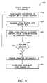
- FIG. 6illustrates a flowchart 600 for developing a training parameter set for the PCMM 100 .
- the training parameter setcomprises information stored in the lookup table 525 and may correspond to a plurality of angular values for each degree of freedom of the measuring arm 105 or rotational cycles for each encoder that may be used to achieve the selected angular values. This information may be used to determine the current position of the measuring arm 105 and provide instructions to the controller 520 associated with each articulated section 515 which direct the measuring arm 105 to a desired location.
- the training parameter setprovides an error mapping functionality that may be used for purposes of self-calibration and adjustment by resolving the current and desired positional information.
- the training parameter setdefines the characteristics and positional adjustment parameters associated with a particular instrument or configuration. These parameters may be applied to similar instruments or configurations such that the parameters developed for one instrument may be used to train or clone another instrument.
- the portable nature of the parameter setdesirably provides a means to calibrate multiple instruments in a more efficient manner than by calibrating each instrument independently of one another.
- the training parameter setrepresents a relatively large number of values relating to a collection of articulations of the measuring arm 105 in three dimensional space.
- This informationmay comprise between approximately 100–10000 different articulations of the measuring arm 105 and the corresponding encoder values relating to these articulations. Consequently, it is desirable to provide the ability to “share” this information between different instruments such that the training parameter set need only be developed on a first instrument. This feature improves the speed with which instrument calibrations may be performed in subsequent instruments and represents a significant time saving feature.
- the training parameter setneed not necessarily be shared between instruments and can be developed independently for each instrument.
- the development of the training parameter setcommences in state 610 wherein instructions for positioning the measuring arm 105 in a selected location and orientation are identified and issued to the controller 520 to effectuate the desired movements of the outer member 132 which in turn aligns and positions the inner member 130 as previously described.
- these instructionsrelate to specified angular values for each degree of freedom of the outer member 132 and/or encoder cycles associated with the encoders 284 and actuator controllers 530 of the outer member 132 .
- the actual location and orientation of the inner members 130 of the measuring arm 105are determined in state 620 .
- This informationmay include the values associated with the encoders 282 of the inner member 130 for each articulation member 515 as well as geometry information acquired by the probe 110 which identifies its location in three dimensional space.
- the training parameter setassociates a collection of outer member encoder values with a corresponding collection of inner member encoder values.
- this informationdesirably provides a means to not only direct a desired positioning and alignment of the measuring arm 105 but also to resolve the current position and alignment of the measuring arm 105 on the basis of the stored encoder values.
- entries in the lookup table 525are populated by associating each set of encoder values for the outer members 132 (e.g. for each axis, degree of freedom, or join member) with encoder values for the inner members 130 . In this manner, encoder values or instructions for actuator assisted positioning of the measuring arm 105 via the outer member 132 may be determined to achieve a plurality actual measuring arm locations.
- Stored entries in the lookup table 525may be subsequently accessed by the controller 520 to effectuate accurate and precise movement of the measuring arm 105 .
- the controller 520may access an appropriate entry in the lookup table 525 corresponding to the desired location (specified by the inner member encoder values) and drive the actuators 305 associated with the outer members 132 to achieve the corresponding outer member encoder values. Utilization of the lookup table 525 in this manner therefore provides a deterministic means to position the arm in a robotically controlled manner without the need to manually “guide” the arm to a desired location.
- each entry in the lookup table 525relates to a singular position or orientation of the measuring arm 105 a plurality of such entries is desirably determined to define a range of potential measuring arm articulations that may be accessed to position the measuring arm in three dimensional space.
- one or more additional operations 610 , 620 , 630may be performed as illustrated by decision state 640 .
- lookup table entries determined according to the aforementioned stepsmay be iteratively performed by the training program 540 which specifies a series of outer member encoder values to be associated with corresponding inner member encoder values when the measuring arm 105 is positioned or oriented.
- the training program 540may specify a collection of outer member encoder values in which each axis or degree of freedom of the measuring arm 105 is positioned a pre-selected amount and the associated inner member encoder values corresponding to these positions is determined and stored in the lookup table 525 .
- increasingly large numbers of entries in the lookup table 525improve the “resolution” of positioning the measuring arm 105 and may comprise between 1000–10000 entries to provide relatively high resolution in a seven axis measuring arm system.
- the use of the training program 540desirably alleviates the need for an operator to manually position the measuring arm 105 when populating the lookup table 525 however it will be appreciated that manual selection and determination of lookup table entries may also be performed as desired.
- training parameter entry determinationmay be performed multiple times for selected locations to establish correction factors, offset values, or variability ranges which may be also stored in the lookup table 525 .
- the lookup table 525may be refined and validated prior to use or dissemination to other instruments.
- this informationmay be re-used as a reference for other similar instruments.
- a comprehensive training parameter setmay serve as a basis for cloning other instruments wherein the lookup table 525 is accessed by a similar instrument without redeveloping the entire contents of the training parameter set and lookup table 525 . In this fashion, subsequent cloned instruments may be more rapidly calibrated as they are able to make use of the existing training parameter set.
- lookup table 525development and training parameter portability can be readily appreciated when the number of individual calibration points used for instrument calibration is large. For example, it is not uncommon for between approximately 1000–10000 individual calibration points to be used during instrument calibration. Training parameter set development need only be performed once however and this information may be shared between similar or compatible instruments thus alleviating the need to re-perform these operations for each instrument. Such a manner of calibration is a notable improvement over existing or conventional methods which require each instrument to be individually calibrated.
- the sensitivity of a measuring arm employing an encoder driven outer member structurecan result in sensitivity on the order of approximately 10–50 microns or better. Additionally, the reproducibility of measuring arm positioning is superior to conventional systems resulting in part from the feedback loop created by the inner and outer member encoders 282 , 284 as well as the use of the lookup table 525 for purposes of directing the actuators 305 .
- FIG. 7illustrates an exemplary lookup table entry 700 that may be generated and utilized as described above.
- the lookup table 525comprises a plurality of such entries 700 which relate outer and inner encoder values 705 , 710 for each axis or degree of freedom 715 of the measuring arm 105 based upon a selected position and/or orientation of the measuring arm 105 .
- Each entry 700may comprise information in addition to the encoder values 705 , 710 which may include for example: a gear ratio 720 associated with the outer member for each axis 715 , an outer member encoder resolution 725 and an inner member encoder resolution 730 (illustrated as cycles per revolution of the encoder), and an approximate articulation angle 735 for each axis of the outer member 132 based upon the specified encoder values 705 .
- This information in addition to the encoder values 705 , 710may be used for a variety of purposes including performing interpolation operations to identify appropriate encoder and actuator positionings that may be used to achieve measuring arm positions or orientations that are not found in the lookup table 525 . In such instances, a best fit or closest match approach may be used to identify suitable actuator movements based upon existing information contained in the lookup table 525 .
- the aforementioned table entry 700represents but one embodiment of the type of information that may be stored in the lookup table 525 .
- the nature of the contents of the lookup table 525may deviate somewhat from that illustrated while still achieving similar results in relating inner and outer member encoder positions or values.
- the lookup table 525serves to not only provide a means to determine the appropriate positioning of the measuring arm 105 but may also be used to ascertain the current position of the measuring arm 105 on the basis of the actuator information.
- the interpolation operationsmay identify two or more entries 700 in the lookup table 525 and use the information contained therein to develop a new entry which may be stored in the lookup table 525 and used to position the measuring arm 105 .
- These extrapolation operationstherefore may be used to not only position the measuring arm 105 but also create the potential for a dynamic or evolving lookup table 525 which may incorporate additional entries beyond those initially identified during training parameter development.
- the aforementioned robotic measuring system 100may be configured to operate in an assisted-movement mode or “joystick-enabled” mode. In this mode of operation, positioning of the measuring arm 105 may be accomplished by an operator who guides the apparatus in various desired directions and/or orientations by exerting pressure or force upon portions of selected inner members 130 .
- the system 100is configured to detect and be responsive to relatively slight movements of the inner member 130 without requiring the operator to exert a force sufficient to move the entire measuring arm 105 and associated hardware components.
- a high level of sensitivityis achievable in detecting movements or changes in position of the inner member 130 as a result of the deformable characteristics of the compliant member 135 and the position detecting means of the pressure sensors, strain gauges, and or encoders as described above.
- a slight manually-exerted force upon selected inner members 130may be detected by the system 100 which may ascertain both the relative amount of force applied and direction of movement against the complain member 135 .
- the system 100may respond with selected actuator-driven movements of the measuring arm 105 in the general direction and orientation of the manually exerted force providing means for the operator to “guide” the movement of the measuring arm 105 with relatively little effort.
- Guided movement or positioning of the measuring arm 105 in the aforementioned mannermay be accomplished by controller-based monitoring of the position and orientation of the measuring arm 105 using information provided by encoders, pressure sensors, and/or strain gauges.
- the controller 520may detect an exerted force upon the measuring arm components based upon a change in position and/or orientation of the inner members 132 from an established or static position.
- the magnitude of the exerted force used to initiate assisted-movementmay be configured as desired and may be relatively small, wherein only a slight movement of the inner member 130 with respect the outer member 132 is needed to effectuate a degree of robotically driven movement.
- an operatormay exert a force against a selected section of the inner member 132 in a desired direction.
- This forceneed not necessarily be large enough to move the entire measuring arm 105 but rather be sufficient to result in some degree of movement of the inner member 130 .
- the controller 520may be configured to discern the relative direction of the exerted force based upon what support webs 135 are deformed and/or the change in position of the inner member 130 with respect to the outer member 132 (as detected by the encoders, pressure sensors, and/or strain gauges).
- the controller 520may instruct appropriate actuators 305 to direct movement of the measuring arm 105 at a pre-selected rate of speed and/or distance for a selected period of time or until the exerted force is no longer detected. Based on this principal, manually-guided movement of the measuring arm 105 can be accomplished to facilitate manual positioning of the measuring arm 105 in such a manner so as to significantly reduce operator fatigue and effort in aligning and calibrating the instrument 100 .
- a selected threshold level of exerted force or detected movementmay be required to initiate the assisted-movement mode.
- the magnitude of the exerted force or detected movementmay be assessed to determine the characteristics of the assisted-movement to be used (e.g. speed, duration, distance, orientation, etc.).
- changes in position of the various measuring arm components which fall below the threshold levelmay be perceived as perturbations which may be corrected for by issuing compensatory instructions to selected actuators 305 to realign or position the measuring arm 105 in a desired manner to offset the detected perturbation(s).
- the controller 520may also be configured to resist movement and maintain current positioning of the measuring arm 105 .
- the operatormay desire the measuring arm 105 to retain a selected position or compensate for undesired movement of the measuring arm 105 .
- the controller 520may be configured to maintain a selected positioning and/or orientation of the measuring arm 105 and actively resist applied or exerted force against the various measuring arm components through application of an actuated controlled “counter-force”. Deviation of the measuring arm 105 from a desired position may also be corrected by the controller 520 which utilizes the lookup table 525 to return the measuring arm 105 to the desired position.
- the measuring arm 105may be positioned and oriented in a number of different ways including substantially autonomous modes wherein the measuring arm is robotically positioned as determined by the controller 520 . Additionally, the measuring arm 105 may be positioned in a semi-automated or manually assisted mode in addition to conventional manually operated modes without robotic assistance. Taken together the features and functionalities of the system as described by the present teachings provide a number of significant improvements over conventional articulated measuring arm configurations. In particular, robotically controlled and/or assisted movement of the measuring arm 105 provides the potential for improved accuracy and precision in acquisition of coordinate data.
- the positioning and alignment detection means in which an inner arm member is driven by an outer arm membermay be adapted for purposes other than coordinate data acquisition. It is conceived that configurations employing an articulated arm having a instrument, tool or other component that is to be finely positioned may be adapted to for use with the present teachings to provide improved response, control, and accuracy in using the tool or other component. For example, in surgical applications a conventional metal or laser scalpel may be adapted for use with a measuring arm wherein the positioning and alignment system of the present teachings provides accurate orientation and manipulation of the scalpel such that surgical procedures can be performed in an autonomous or semi-autonomous manner with a high degree of precision.
Landscapes
- Physics & Mathematics (AREA)
- General Physics & Mathematics (AREA)
- Length Measuring Devices With Unspecified Measuring Means (AREA)
- A Measuring Device Byusing Mechanical Method (AREA)
- Manipulator (AREA)
Abstract
Description
Claims (66)
Priority Applications (7)
| Application Number | Priority Date | Filing Date | Title |
|---|---|---|---|
| US10/758,697US7152456B2 (en) | 2004-01-14 | 2004-01-14 | Automated robotic measuring system |
| EP04812142.0AEP1718924B1 (en) | 2004-01-14 | 2004-11-23 | Robotic measuring system comprising an articulated supporting arm and an articulated measuring arm |
| PCT/US2004/039561WO2005071351A2 (en) | 2004-01-14 | 2004-11-23 | Robotic measuring system comprising an articulated supporting arm and an articulated measuring arm |
| CA2553476ACA2553476C (en) | 2004-01-14 | 2004-11-23 | Automated robotic measuring system |
| US11/614,874US7578069B2 (en) | 2004-01-14 | 2006-12-21 | Automated robotic measuring system |
| US11/614,932US7441341B2 (en) | 2004-01-14 | 2006-12-21 | Automated robotic measuring system |
| US14/316,207US9734609B2 (en) | 2004-01-14 | 2014-06-26 | Transprojection of geometry data |
Applications Claiming Priority (1)
| Application Number | Priority Date | Filing Date | Title |
|---|---|---|---|
| US10/758,697US7152456B2 (en) | 2004-01-14 | 2004-01-14 | Automated robotic measuring system |
Related Child Applications (2)
| Application Number | Title | Priority Date | Filing Date |
|---|---|---|---|
| US11/614,932DivisionUS7441341B2 (en) | 2004-01-14 | 2006-12-21 | Automated robotic measuring system |
| US11/614,874ContinuationUS7578069B2 (en) | 2004-01-14 | 2006-12-21 | Automated robotic measuring system |
Publications (2)
| Publication Number | Publication Date |
|---|---|
| US20050150123A1 US20050150123A1 (en) | 2005-07-14 |
| US7152456B2true US7152456B2 (en) | 2006-12-26 |
Family
ID=34740148
Family Applications (3)
| Application Number | Title | Priority Date | Filing Date |
|---|---|---|---|
| US10/758,697Expired - LifetimeUS7152456B2 (en) | 2004-01-14 | 2004-01-14 | Automated robotic measuring system |
| US11/614,932Expired - LifetimeUS7441341B2 (en) | 2004-01-14 | 2006-12-21 | Automated robotic measuring system |
| US11/614,874Expired - LifetimeUS7578069B2 (en) | 2004-01-14 | 2006-12-21 | Automated robotic measuring system |
Family Applications After (2)
| Application Number | Title | Priority Date | Filing Date |
|---|---|---|---|
| US11/614,932Expired - LifetimeUS7441341B2 (en) | 2004-01-14 | 2006-12-21 | Automated robotic measuring system |
| US11/614,874Expired - LifetimeUS7578069B2 (en) | 2004-01-14 | 2006-12-21 | Automated robotic measuring system |
Country Status (4)
| Country | Link |
|---|---|
| US (3) | US7152456B2 (en) |
| EP (1) | EP1718924B1 (en) |
| CA (1) | CA2553476C (en) |
| WO (1) | WO2005071351A2 (en) |
Cited By (60)
| Publication number | Priority date | Publication date | Assignee | Title |
|---|---|---|---|---|
| US20050151963A1 (en)* | 2004-01-14 | 2005-07-14 | Sandeep Pulla | Transprojection of geometry data |
| US20070163136A1 (en)* | 2004-01-14 | 2007-07-19 | Homer Eaton | Automated robotic measuring system |
| US20070175283A1 (en)* | 2006-02-01 | 2007-08-02 | General Electric Company | Systems and Methods for Remote Monitoring of Vibrations in Machines |
| US20070256311A1 (en)* | 2006-05-01 | 2007-11-08 | Paul Ferrari | Sealed battery for coordinate measurement machine |
| US20080127501A1 (en)* | 2006-11-20 | 2008-06-05 | Eaton Homer L | Coordinate measurement machine with improved joint |
| US20080295352A1 (en)* | 2007-05-31 | 2008-12-04 | Brunson Deighton E | Length reference bar system and method |
| US20090010740A1 (en)* | 2008-03-28 | 2009-01-08 | Paul Ferrari | Coordinate measuring machine with rotatable grip |
| US20090013548A1 (en)* | 2006-12-22 | 2009-01-15 | Paul Ferrari | Joint axis for coordinate measurement machine |
| US20090013547A1 (en)* | 2007-07-09 | 2009-01-15 | Paul Ferrari | Joint for coordinate measurement device |
| US20090083985A1 (en)* | 2007-09-28 | 2009-04-02 | Romer / Cimcore | Coordinate measurement machine |
| USD599226S1 (en) | 2008-04-11 | 2009-09-01 | Hexagon Metrology, Inc. | Portable coordinate measurement machine |
| US20090241360A1 (en)* | 2008-03-28 | 2009-10-01 | Hogar Tait | Systems and methods for improved coordination acquisition member comprising calibration information |
| US20090271996A1 (en)* | 2008-05-05 | 2009-11-05 | Paul Ferrari | Systems and methods for calibrating a portable coordinate measurement machine |
| US7805854B2 (en) | 2006-05-15 | 2010-10-05 | Hexagon Metrology, Inc. | Systems and methods for positioning and measuring objects using a CMM |
| US20100325907A1 (en)* | 2009-06-30 | 2010-12-30 | Hexagon Metrology Ab | Coordinate measurement machine with vibration detection |
| US7908757B2 (en) | 2008-10-16 | 2011-03-22 | Hexagon Metrology, Inc. | Articulating measuring arm with laser scanner |
| US20110112786A1 (en)* | 2009-11-06 | 2011-05-12 | Hexagon Metrology Ab | Cmm with improved sensors |
| US20110173828A1 (en)* | 2010-01-20 | 2011-07-21 | Faro Technologies, Inc. | Intelligent repeatable arm mounting system |
| USD643319S1 (en) | 2010-03-29 | 2011-08-16 | Hexagon Metrology Ab | Portable coordinate measurement machine |
| US20110213247A1 (en)* | 2010-01-08 | 2011-09-01 | Hexagon Metrology, Inc. | Articulated arm with imaging device |
| US8127458B1 (en) | 2010-08-31 | 2012-03-06 | Hexagon Metrology, Inc. | Mounting apparatus for articulated arm laser scanner |
| US8284407B2 (en) | 2010-01-20 | 2012-10-09 | Faro Technologies, Inc. | Coordinate measuring machine having an illuminated probe end and method of operation |
| US8533967B2 (en) | 2010-01-20 | 2013-09-17 | Faro Technologies, Inc. | Coordinate measurement machines with removable accessories |
| US8615893B2 (en) | 2010-01-20 | 2013-12-31 | Faro Technologies, Inc. | Portable articulated arm coordinate measuring machine having integrated software controls |
| US8630314B2 (en) | 2010-01-11 | 2014-01-14 | Faro Technologies, Inc. | Method and apparatus for synchronizing measurements taken by multiple metrology devices |
| US8638446B2 (en) | 2010-01-20 | 2014-01-28 | Faro Technologies, Inc. | Laser scanner or laser tracker having a projector |
| US8677643B2 (en) | 2010-01-20 | 2014-03-25 | Faro Technologies, Inc. | Coordinate measurement machines with removable accessories |
| US8763267B2 (en) | 2012-01-20 | 2014-07-01 | Hexagon Technology Center Gmbh | Locking counterbalance for a CMM |
| US8832954B2 (en) | 2010-01-20 | 2014-09-16 | Faro Technologies, Inc. | Coordinate measurement machines with removable accessories |
| US8875409B2 (en) | 2010-01-20 | 2014-11-04 | Faro Technologies, Inc. | Coordinate measurement machines with removable accessories |
| US8898919B2 (en) | 2010-01-20 | 2014-12-02 | Faro Technologies, Inc. | Coordinate measurement machine with distance meter used to establish frame of reference |
| US8997362B2 (en) | 2012-07-17 | 2015-04-07 | Faro Technologies, Inc. | Portable articulated arm coordinate measuring machine with optical communications bus |
| US9069355B2 (en) | 2012-06-08 | 2015-06-30 | Hexagon Technology Center Gmbh | System and method for a wireless feature pack |
| US9074883B2 (en) | 2009-03-25 | 2015-07-07 | Faro Technologies, Inc. | Device for optically scanning and measuring an environment |
| US9113023B2 (en) | 2009-11-20 | 2015-08-18 | Faro Technologies, Inc. | Three-dimensional scanner with spectroscopic energy detector |
| US9163922B2 (en) | 2010-01-20 | 2015-10-20 | Faro Technologies, Inc. | Coordinate measurement machine with distance meter and camera to determine dimensions within camera images |
| US9163921B2 (en) | 2013-12-18 | 2015-10-20 | Hexagon Metrology, Inc. | Ultra-portable articulated arm coordinate measurement machine |
| US9168654B2 (en) | 2010-11-16 | 2015-10-27 | Faro Technologies, Inc. | Coordinate measuring machines with dual layer arm |
| US9210288B2 (en) | 2009-11-20 | 2015-12-08 | Faro Technologies, Inc. | Three-dimensional scanner with dichroic beam splitters to capture a variety of signals |
| US9250214B2 (en) | 2013-03-12 | 2016-02-02 | Hexagon Metrology, Inc. | CMM with flaw detection system |
| US9329271B2 (en) | 2010-05-10 | 2016-05-03 | Faro Technologies, Inc. | Method for optically scanning and measuring an environment |
| US9372265B2 (en) | 2012-10-05 | 2016-06-21 | Faro Technologies, Inc. | Intermediate two-dimensional scanning with a three-dimensional scanner to speed registration |
| US9417056B2 (en) | 2012-01-25 | 2016-08-16 | Faro Technologies, Inc. | Device for optically scanning and measuring an environment |
| US9417316B2 (en) | 2009-11-20 | 2016-08-16 | Faro Technologies, Inc. | Device for optically scanning and measuring an environment |
| US9513107B2 (en) | 2012-10-05 | 2016-12-06 | Faro Technologies, Inc. | Registration calculation between three-dimensional (3D) scans based on two-dimensional (2D) scan data from a 3D scanner |
| US9529083B2 (en) | 2009-11-20 | 2016-12-27 | Faro Technologies, Inc. | Three-dimensional scanner with enhanced spectroscopic energy detector |
| US9551575B2 (en) | 2009-03-25 | 2017-01-24 | Faro Technologies, Inc. | Laser scanner having a multi-color light source and real-time color receiver |
| US9594250B2 (en) | 2013-12-18 | 2017-03-14 | Hexagon Metrology, Inc. | Ultra-portable coordinate measurement machine |
| US9607239B2 (en) | 2010-01-20 | 2017-03-28 | Faro Technologies, Inc. | Articulated arm coordinate measurement machine having a 2D camera and method of obtaining 3D representations |
| US9628775B2 (en) | 2010-01-20 | 2017-04-18 | Faro Technologies, Inc. | Articulated arm coordinate measurement machine having a 2D camera and method of obtaining 3D representations |
| US9759540B2 (en) | 2014-06-11 | 2017-09-12 | Hexagon Metrology, Inc. | Articulating CMM probe |
| US10067231B2 (en) | 2012-10-05 | 2018-09-04 | Faro Technologies, Inc. | Registration calculation of three-dimensional scanner data performed between scans based on measurements by two-dimensional scanner |
| US10175037B2 (en) | 2015-12-27 | 2019-01-08 | Faro Technologies, Inc. | 3-D measuring device with battery pack |
| US10281259B2 (en) | 2010-01-20 | 2019-05-07 | Faro Technologies, Inc. | Articulated arm coordinate measurement machine that uses a 2D camera to determine 3D coordinates of smoothly continuous edge features |
| USD875573S1 (en) | 2018-09-26 | 2020-02-18 | Hexagon Metrology, Inc. | Scanning device |
| US10969760B2 (en) | 2018-04-12 | 2021-04-06 | Faro Technologies, Inc. | Coordinate measurement system with auxiliary axis |
| US11022434B2 (en) | 2017-11-13 | 2021-06-01 | Hexagon Metrology, Inc. | Thermal management of an optical scanning device |
| US20210236220A1 (en)* | 2016-07-14 | 2021-08-05 | Intuitive Surgical Operations, Inc. | Techniques for controlling a moveable component |
| US20220119096A1 (en)* | 2016-10-13 | 2022-04-21 | Alexander I. Poltorak | Apparatus and method for balancing aircraft with robotic arms |
| US11874101B2 (en) | 2018-04-12 | 2024-01-16 | Faro Technologies, Inc | Modular servo cartridges for precision metrology |
Families Citing this family (43)
| Publication number | Priority date | Publication date | Assignee | Title |
|---|---|---|---|---|
| AU2003223173A1 (en)* | 2002-02-14 | 2003-09-04 | Faro Technologies, Inc. | Portable coordinate measurement machine with integrated line laser scanner |
| US7073271B2 (en)* | 2002-02-14 | 2006-07-11 | Faro Technologies Inc. | Portable coordinate measurement machine |
| CA2522097C (en)* | 2003-04-28 | 2012-09-25 | Stephen James Crampton | Cmm arm with exoskeleton |
| US8123350B2 (en)* | 2003-06-03 | 2012-02-28 | Hexagon Metrology Ab | Computerized apparatus and method for applying graphics to surfaces |
| US20050234565A1 (en)* | 2004-04-01 | 2005-10-20 | Systems, Machines, Automation Components, Corporation | Programmable control system for automated actuator operation |
| KR20060038525A (en)* | 2004-10-30 | 2006-05-04 | 한국전력공사 | 3-axis displacement measuring device |
| GB0501690D0 (en)* | 2005-01-27 | 2005-03-02 | Renishaw Plc | Articulating device |
| JP4464318B2 (en)* | 2005-05-16 | 2010-05-19 | オークマ株式会社 | Calibration method for parallel mechanism machine |
| US7395607B1 (en)* | 2005-06-14 | 2008-07-08 | Discovery Technology International, Lllp | Rotational and translational microposition apparatus and method |
| WO2007033273A2 (en)* | 2005-09-13 | 2007-03-22 | Romer Incorporated | Vehicle comprising an articulator of a coordinate measuring machine |
| BRPI0505860A (en)* | 2005-12-09 | 2007-09-25 | Ubea | dental structure digitizer, method for reading three-dimensional data from a dental structure and mouth scanner kit |
| DE102006031580A1 (en) | 2006-07-03 | 2008-01-17 | Faro Technologies, Inc., Lake Mary | Method and device for the three-dimensional detection of a spatial area |
| DE602007009188D1 (en) | 2007-03-26 | 2010-10-28 | Hexagon Metrology Ab | Method of using a multi-axis positioning and measuring system |
| WO2008121073A1 (en)* | 2007-04-03 | 2008-10-09 | Hexagon Metrology Ab | Method and device for exact measurement of objects |
| EP1988357B1 (en) | 2007-05-04 | 2018-10-17 | Hexagon Technology Center GmbH | Coordinate measuring method and device |
| US7979160B2 (en)* | 2007-07-31 | 2011-07-12 | Spirit Aerosystems, Inc. | System and method for robotic accuracy improvement |
| EP2108917B1 (en)* | 2008-04-07 | 2012-10-03 | Leica Geosystems AG | Articulated arm coordinate measuring machine |
| DE102008024713A1 (en)* | 2008-05-22 | 2009-12-03 | Carl Zeiss Industrielle Messtechnik Gmbh | Cladding for a machine, in particular for a coordinate measuring machine |
| US8439899B2 (en) | 2008-09-11 | 2013-05-14 | Ntn Corporation | Remote-controlled actuator |
| WO2010061567A1 (en)* | 2008-11-27 | 2010-06-03 | Ntn株式会社 | Remote control actuator |
| DE102009045688A1 (en)* | 2009-10-14 | 2011-04-28 | Dreier Lasermesstechnik Gmbh | Device for checking the accuracy of a circular path of a machine tool to be executed by a work spindle and / or a machine table |
| EP2627969A1 (en)* | 2010-10-12 | 2013-08-21 | Stephen James Crampton | Hover cmm |
| JP5754971B2 (en)* | 2011-02-14 | 2015-07-29 | キヤノン株式会社 | Shape measuring apparatus and shape measuring method |
| CN103049627A (en)* | 2011-10-13 | 2013-04-17 | 鸿富锦精密工业(深圳)有限公司 | Generating system and method for deviation range of measured data |
| JP5661718B2 (en)* | 2012-10-12 | 2015-01-28 | ファナック株式会社 | Robot linear body mounting device |
| US8910391B2 (en)* | 2013-01-24 | 2014-12-16 | Faro Technologies, Inc. | Non-articulated portable CMM |
| US20140260711A1 (en)* | 2013-03-12 | 2014-09-18 | Larry A. Turner | Probe balancer |
| DE102013204581A1 (en)* | 2013-03-15 | 2014-09-18 | Carl Zeiss Industrielle Messtechnik Gmbh | Method for correcting an angular deviation in the operation of a coordinate measuring machine |
| US20140327746A1 (en)* | 2013-05-06 | 2014-11-06 | Iphoton Solutions, Llc | Volume reconstruction of an object using a 3d sensor and robotic coordinates |
| US9958854B2 (en)* | 2013-06-10 | 2018-05-01 | The Boeing Company | Systems and methods for robotic measurement of parts |
| US10258417B2 (en)* | 2014-01-24 | 2019-04-16 | Koninklijke Philips N.V. | Sensorless force control for transeopagel echocardiography probe |
| KR102177156B1 (en) | 2014-03-10 | 2020-11-10 | 삼성전자주식회사 | robot and substrate processing apparatus including the same |
| CN103884302B (en)* | 2014-03-20 | 2016-04-13 | 安凯 | The collision checking method of space manipulator and cabin body |
| JP6460697B2 (en)* | 2014-03-27 | 2019-01-30 | キヤノン株式会社 | Angle detection method, angle detection apparatus, and robot apparatus |
| US9375841B1 (en) | 2014-05-28 | 2016-06-28 | Google Inc. | Robotic devices with ambient indications of joint status |
| US9501059B2 (en)* | 2014-09-12 | 2016-11-22 | Qualcomm Incorporated | Pocket robot |
| US9676097B1 (en)* | 2014-11-11 | 2017-06-13 | X Development Llc | Systems and methods for robotic device authentication |
| CN105157638A (en)* | 2015-06-26 | 2015-12-16 | 合肥工业大学 | Variable-arm-length articulated-type coordinate measuring machine |
| CN106500641B (en)* | 2016-10-21 | 2018-12-14 | 北京信息科技大学 | The thermal deformation error compensating method of articulated coordinate machine |
| US10895445B2 (en)* | 2018-09-14 | 2021-01-19 | Faro Technologies, Inc. | Articulated arm coordinate measuring machines with active counterbalance |
| US12066808B2 (en)* | 2021-11-24 | 2024-08-20 | Hexagon Metrology, Inc. | Parametric and modal work-holding method for automated inspection |
| US12416483B2 (en) | 2021-11-24 | 2025-09-16 | Hexagon Metrology, Inc. | Parametric and modal work-holding apparatus |
| US12343860B2 (en) | 2021-11-24 | 2025-07-01 | Hexagon Metrology, Inc. | Automated work-holding for precise fastening of light parts during automated transfer |
Citations (48)
| Publication number | Priority date | Publication date | Assignee | Title |
|---|---|---|---|---|
| US2076446A (en)* | 1934-02-10 | 1937-04-06 | Terry Herbert & Sons Ltd | Equipoising mechanism |
| US2787434A (en)* | 1954-01-27 | 1957-04-02 | Jacobsen As J | Equipoised lamp structure |
| US3713453A (en)* | 1971-04-05 | 1973-01-30 | J Chiaro | Apparatus for styling hair |
| US3757190A (en) | 1972-02-18 | 1973-09-04 | Redifon Ltd | Slip ring electrical connections |
| US3944798A (en) | 1974-04-18 | 1976-03-16 | Eaton-Leonard Corporation | Method and apparatus for measuring direction |
| US4016803A (en)* | 1974-11-12 | 1977-04-12 | Danfoss A/S | Servo device |
| US4119212A (en)* | 1977-07-18 | 1978-10-10 | Western Electric Company, Inc. | Monitoring the location of a robot hand |
| US4160536A (en)* | 1976-10-27 | 1979-07-10 | Jac. Jacobsen A/S | Counterbalanced arm |
| US4313263A (en) | 1977-02-07 | 1982-02-02 | Rolls Royce Limited | Method and apparatus for use in co-ordinate measuring machines |
| US4326155A (en)* | 1980-06-03 | 1982-04-20 | Griebeler Elmer L | Shockwave probe |
| GB2097359A (en)* | 1981-04-23 | 1982-11-03 | Bisiach Luciano | Industrial robot with several axes of rotation |
| US4382215A (en) | 1981-07-16 | 1983-05-03 | General Electric Company | System and method of precision machining |
| US4388758A (en) | 1980-03-05 | 1983-06-21 | Johannes Heidenhain Gmbh | Digital electrical angle-measuring device |
| US4496279A (en) | 1982-12-09 | 1985-01-29 | Mts Systems Corporation | Robot arm and wrist assembly |
| US4593470A (en) | 1982-07-14 | 1986-06-10 | Micro Control Systems, Inc. | Portable three dimensional graphics tablet |
| US4606696A (en) | 1984-06-25 | 1986-08-19 | Slocum Alexander H | Mechanism to determine position and orientation in space |
| US4631404A (en) | 1984-04-21 | 1986-12-23 | Johannes Heidenhain Gmbh | Position measuring system |
| US4667096A (en) | 1984-03-31 | 1987-05-19 | Johannes Heidenhain Gmbh | Position measuring system comprising at least two scanning units |
| US4676002A (en) | 1984-06-25 | 1987-06-30 | Slocum Alexander H | Mechanisms to determine position and orientation in space |
| US4703443A (en) | 1984-02-16 | 1987-10-27 | Kabushiki Kaisha Toshiba | Device for measuring the shape of a three-dimensional object |
| US4718023A (en)* | 1984-11-27 | 1988-01-05 | Photo Acoustic Technology, Inc. | Ultrasonic apparatus for positioning a robot hand |
| US4751868A (en)* | 1986-02-12 | 1988-06-21 | Paynter Henry M | Method and system employing double-acting, fluid-driven twistor-pairs as combined joints and motors in arthrobots |
| US4839646A (en) | 1986-02-28 | 1989-06-13 | Royal Melbourne Institute Of Technology Limited | Movement parameter sensor |
| US4857926A (en) | 1987-08-25 | 1989-08-15 | Honeywell Inc. | Phase-responsive angular tracking device |
| JPH01222883A (en)* | 1988-02-26 | 1989-09-06 | Mitsubishi Electric Corp | Hand device for robot |
| US4888877A (en) | 1987-11-26 | 1989-12-26 | Carl-Zeiss-Stiftung, Heidenhein/Brenz | Articulating head for a coordinate-measuring instrument |
| US4913613A (en)* | 1987-07-10 | 1990-04-03 | Hirschmann Gregory C | Linear unit for an assembly device in handling technology |
| US4921393A (en)* | 1988-03-09 | 1990-05-01 | Sri International | Articulatable structure with adjustable end-point compliance |
| US4937759A (en)* | 1986-02-18 | 1990-06-26 | Robotics Research Corporation | Industrial robot with controller |
| US4953822A (en)* | 1987-05-26 | 1990-09-04 | Eldon Industries, Inc. | Adjustable arm structures |
| US5079500A (en) | 1990-02-24 | 1992-01-07 | Ferranti International Plc | Potentiometric circuit arrangement |
| US5084981A (en) | 1989-04-14 | 1992-02-04 | Renishaw Plc | Probe head |
| JPH0457690A (en)* | 1990-06-25 | 1992-02-25 | Hitachi Ltd | Vibration absorbers, drive/load combinations, and multi-axis mechanisms |
| US5148377A (en) | 1986-12-10 | 1992-09-15 | Mcdonald Gregory J | Coordinate measuring system |
| US5155423A (en)* | 1986-02-18 | 1992-10-13 | Robotics Research Corporation | Industrial robot with servo |
| US5174039A (en) | 1990-08-17 | 1992-12-29 | Kabushiki Kaisha Toshiba | Displacement-measuring apparatus, and static-pressure bearing device for use in the displacement-measuring apparatus |
| EP0522610A1 (en) | 1991-06-26 | 1993-01-13 | Sulzer - Escher Wyss AG | Method and apparatus for surface-contour determination of rotor blades in hydraulic machines |
| US5293107A (en) | 1993-02-24 | 1994-03-08 | Fanuc Robotics North America, Inc. | Motorized rotary joint and method of constructing a modular robot utilizing same |
| US5402582A (en) | 1993-02-23 | 1995-04-04 | Faro Technologies Inc. | Three dimensional coordinate measuring apparatus |
| US5796229A (en)* | 1993-09-10 | 1998-08-18 | Fanuc Ltd. | Method and apparatus for robotic force controlled material removal with programmable overload release function |
| US6428266B1 (en)* | 1995-07-10 | 2002-08-06 | Brooks Automation, Inc. | Direct driven robot |
| US6431019B1 (en)* | 2001-03-21 | 2002-08-13 | The United States Of America As Represented By The Secretary Of The Navy | Low cost, high-strength robotic arm |
| DE10112977C1 (en) | 2001-03-17 | 2002-11-21 | Zett Mess Technik Gmbh | Height measurement and tracking device for 3-dimensional measurement of workpiece has hydraulically or pneumatically operated brake piston for fixing position of each rotary linkage |
| JP2003275484A (en)* | 2002-03-25 | 2003-09-30 | Brother Ind Ltd | Screen setting device of sewing machine |
| WO2004096502A1 (en) | 2003-04-28 | 2004-11-11 | Stephen James Crampton | Cmm arm with exoskeleton |
| US6819550B2 (en)* | 2001-11-08 | 2004-11-16 | Apple Computer, Inc. | Computer controlled display device |
| US6896230B2 (en)* | 2002-12-30 | 2005-05-24 | Sava Cvek | Equipoise arm assembly |
| US7042714B2 (en)* | 2001-11-08 | 2006-05-09 | Apple Computer, Inc. | Computer controlled display device |
Family Cites Families (63)
| Publication number | Priority date | Publication date | Assignee | Title |
|---|---|---|---|---|
| US4170824A (en)* | 1976-03-31 | 1979-10-16 | Mikulin Tom T | Universal compass |
| IN161120B (en)* | 1983-03-30 | 1987-10-03 | Wyler Ag | |
| JPS60201118A (en) | 1984-03-24 | 1985-10-11 | Mitsubishi Electric Corp | Automatically coupling joint of testing device |
| US4654956A (en)* | 1985-04-16 | 1987-04-07 | Protocad, Inc. | Drill apparatus for use with computer controlled plotter |
| JPS61252093A (en)* | 1985-04-30 | 1986-11-10 | 株式会社日立製作所 | Wrist mechanism of industrial robot |
| JPH0641117B2 (en)* | 1986-06-13 | 1994-06-01 | 株式会社日立製作所 | Robot wrist device |
| JPH0224075A (en)* | 1988-07-13 | 1990-01-26 | Mitsubishi Electric Corp | Industrial robot |
| DE3939836A1 (en)* | 1988-12-02 | 1990-06-07 | Tokico Ltd | INDUSTRIAL ROBOT |
| US5007784A (en)* | 1989-01-20 | 1991-04-16 | Genmark Automation | Dual end effector robotic arm |
| DE69003149T2 (en) | 1989-04-14 | 1994-01-05 | Renishaw Plc | Probe. |
| JPH02290506A (en) | 1989-04-28 | 1990-11-30 | Mitsutoyo Corp | Three-dimensional measuring instrument |
| JPH03154791A (en)* | 1989-11-14 | 1991-07-02 | Sumitomo Eaton Noba Kk | Articulated arm for robot |
| JPH0432393A (en) | 1990-05-29 | 1992-02-04 | Sharp Corp | color imaging device |
| FR2674017B1 (en)* | 1991-03-12 | 1995-01-13 | Romer Srl | DEVICE FOR MEASURING THE SHAPE OR POSITION OF AN OBJECT. |
| JP3005136B2 (en)* | 1992-04-27 | 2000-01-31 | キヤノン株式会社 | Printing apparatus and printing method |
| DE4327250C5 (en) | 1992-09-25 | 2008-11-20 | Carl Zeiss Industrielle Messtechnik Gmbh | Method for measuring coordinates on workpieces |
| DE4238139C2 (en) | 1992-11-12 | 2002-10-24 | Zeiss Carl | The coordinate |
| GB2274526A (en) | 1993-01-21 | 1994-07-27 | Motorola Inc | Verifying geometry of a part |
| US5408754A (en) | 1993-02-23 | 1995-04-25 | Faro Technologies, Inc. | Method and apparatus for measuring sleeping positions |
| US5412880A (en) | 1993-02-23 | 1995-05-09 | Faro Technologies Inc. | Method of constructing a 3-dimensional map of a measurable quantity using three dimensional coordinate measuring apparatus |
| US5611147A (en) | 1993-02-23 | 1997-03-18 | Faro Technologies, Inc. | Three dimensional coordinate measuring apparatus |
| US6535794B1 (en) | 1993-02-23 | 2003-03-18 | Faro Technologoies Inc. | Method of generating an error map for calibration of a robot or multi-axis machining center |
| US5724264A (en) | 1993-07-16 | 1998-03-03 | Immersion Human Interface Corp. | Method and apparatus for tracking the position and orientation of a stylus and for digitizing a 3-D object |
| FR2710407B1 (en) | 1993-09-20 | 1995-12-01 | Romer Srl | Positioning method for a three-dimensional measuring machine and device for implementing the method. |
| US5505003A (en) | 1993-10-08 | 1996-04-09 | M&M Precision Systems Corporation | Generative measuring system |
| DE4345091C2 (en) | 1993-12-31 | 1995-10-05 | Perthen Feinpruef Gmbh | Probe with multi-dimensional touch probe |
| FR2721395B1 (en) | 1994-06-17 | 1996-08-14 | Homer Eaton | Method for locating a trihedron in space and device for implementing this method. |
| US5521847A (en) | 1994-07-01 | 1996-05-28 | General Electric Company | System and method for determining airfoil characteristics from coordinate measuring machine probe center data |
| US5510977A (en) | 1994-08-02 | 1996-04-23 | Faro Technologies Inc. | Method and apparatus for measuring features of a part or item |
| US5822450A (en) | 1994-08-31 | 1998-10-13 | Kabushiki Kaisha Toshiba | Method for monitoring equipment state by distribution measurement data, and equipment monitoring apparatus |
| GB9515311D0 (en) | 1995-07-26 | 1995-09-20 | 3D Scanners Ltd | Stripe scanners and methods of scanning |
| FR2740546B1 (en) | 1995-10-25 | 1998-01-02 | Romer Srl | THREE-DIMENSIONAL MEASURING DEVICE FOR ACCIDENT VEHICLE |
| US5768792A (en) | 1996-02-09 | 1998-06-23 | Faro Technologies Inc. | Method and apparatus for measuring and tube fitting |
| US5829148A (en)* | 1996-04-23 | 1998-11-03 | Eaton; Homer L. | Spatial measuring device |
| CA2183004A1 (en) | 1996-08-23 | 1998-02-24 | Nino Camurri | Articulated-arm measuring machine and twist-net network |
| US6161079A (en) | 1997-08-18 | 2000-12-12 | Giddings & Lewis, Llc | Method and apparatus for determining tolerance and nominal measurement values for a coordinate measuring machine |
| US5991704A (en) | 1998-03-26 | 1999-11-23 | Chrysler Corporation | Flexible support with indicator device |
| US5978748A (en) | 1998-07-07 | 1999-11-02 | Faro Technologies, Inc. | Host independent articulated arm |
| US6219928B1 (en) | 1998-07-08 | 2001-04-24 | Faro Technologies Inc. | Serial network for coordinate measurement apparatus |
| WO2000007503A1 (en)* | 1998-08-04 | 2000-02-17 | Intuitive Surgical, Inc. | Manipulator positioning linkage for robotic surgery |
| DE29918341U1 (en) | 1999-10-18 | 2001-03-01 | Tassakos Charalambos | Device for determining the position of measuring points of a measuring object relative to a reference system |
| KR100592957B1 (en)* | 2000-02-26 | 2006-06-23 | 삼성전자주식회사 | Work Object Transfer Device |
| FR2806657B1 (en) | 2000-03-21 | 2002-08-16 | Romain Granger | POSITIONAL MARKING SYSTEM OF A THREE-DIMENSIONAL MACHINE IN A FIXED REFERENCE SYSTEM |
| US6668466B1 (en) | 2000-10-19 | 2003-12-30 | Sandia Corporation | Highly accurate articulated coordinate measuring machine |
| US6598306B2 (en) | 2001-04-17 | 2003-07-29 | Homer L. Eaton | Self-loading spatial reference point array |
| JP4680434B2 (en) | 2001-07-09 | 2011-05-11 | 株式会社ナカオ | In-vehicle support base using 3D universal joint |
| US6984236B2 (en) | 2001-10-24 | 2006-01-10 | Faro Technologies, Inc. | Bone connective prosthesis and method of forming same |
| JP4125513B2 (en) | 2001-12-13 | 2008-07-30 | 独立行政法人科学技術振興機構 | Humanoid robot arm |
| US6973734B2 (en) | 2002-02-14 | 2005-12-13 | Faro Technologies, Inc. | Method for providing sensory feedback to the operator of a portable measurement machine |
| US6957496B2 (en) | 2002-02-14 | 2005-10-25 | Faro Technologies, Inc. | Method for improving measurement accuracy of a portable coordinate measurement machine |
| AU2003223173A1 (en) | 2002-02-14 | 2003-09-04 | Faro Technologies, Inc. | Portable coordinate measurement machine with integrated line laser scanner |
| US7246030B2 (en) | 2002-02-14 | 2007-07-17 | Faro Technologies, Inc. | Portable coordinate measurement machine with integrated line laser scanner |
| US7073271B2 (en) | 2002-02-14 | 2006-07-11 | Faro Technologies Inc. | Portable coordinate measurement machine |
| US6952882B2 (en) | 2002-02-14 | 2005-10-11 | Faro Technologies, Inc. | Portable coordinate measurement machine |
| DE60306902T2 (en) | 2002-02-26 | 2007-01-11 | Faro Technologies, Inc., Lake Mary | STANDARD VACUUM ADAPTER |
| US6817108B2 (en) | 2003-02-05 | 2004-11-16 | Homer L. Eaton | Articulation measuring arm having rotatable part-carrying platen |
| US7003892B2 (en) | 2003-04-15 | 2006-02-28 | Hexagon Metrology Ab | Spatial coordinate-based method for identifying work pieces |
| JP2005016972A (en)* | 2003-06-23 | 2005-01-20 | Tokyo Seimitsu Co Ltd | Measuring head |
| FR2861843B1 (en)* | 2003-10-29 | 2006-07-07 | Romain Granger | CONNECTING DEVICE ASSOCIATED WITH A THREE DIMENSIONAL MEASURING APPARATUS ARM WITH ARTICULATED ARMS |
| US7152456B2 (en)* | 2004-01-14 | 2006-12-26 | Romer Incorporated | Automated robotic measuring system |
| JP4073919B2 (en) | 2005-02-07 | 2008-04-09 | 成生 岡 | An aerial positioning stand with a combined articulated arm and flexible tube arm structure |
| CN101156044B (en) | 2005-04-11 | 2011-02-02 | Faro科技有限公司 | Three-dimensional coordinate measuring apparatus |
| WO2007033273A2 (en) | 2005-09-13 | 2007-03-22 | Romer Incorporated | Vehicle comprising an articulator of a coordinate measuring machine |
- 2004
- 2004-01-14USUS10/758,697patent/US7152456B2/ennot_activeExpired - Lifetime
- 2004-11-23CACA2553476Apatent/CA2553476C/ennot_activeExpired - Fee Related
- 2004-11-23EPEP04812142.0Apatent/EP1718924B1/ennot_activeExpired - Lifetime
- 2004-11-23WOPCT/US2004/039561patent/WO2005071351A2/enactiveApplication Filing
- 2006
- 2006-12-21USUS11/614,932patent/US7441341B2/ennot_activeExpired - Lifetime
- 2006-12-21USUS11/614,874patent/US7578069B2/ennot_activeExpired - Lifetime
Patent Citations (52)
| Publication number | Priority date | Publication date | Assignee | Title |
|---|---|---|---|---|
| US2076446A (en)* | 1934-02-10 | 1937-04-06 | Terry Herbert & Sons Ltd | Equipoising mechanism |
| US2787434A (en)* | 1954-01-27 | 1957-04-02 | Jacobsen As J | Equipoised lamp structure |
| US3713453A (en)* | 1971-04-05 | 1973-01-30 | J Chiaro | Apparatus for styling hair |
| US3757190A (en) | 1972-02-18 | 1973-09-04 | Redifon Ltd | Slip ring electrical connections |
| US3944798A (en) | 1974-04-18 | 1976-03-16 | Eaton-Leonard Corporation | Method and apparatus for measuring direction |
| US4016803A (en)* | 1974-11-12 | 1977-04-12 | Danfoss A/S | Servo device |
| US4160536A (en)* | 1976-10-27 | 1979-07-10 | Jac. Jacobsen A/S | Counterbalanced arm |
| US4313263A (en) | 1977-02-07 | 1982-02-02 | Rolls Royce Limited | Method and apparatus for use in co-ordinate measuring machines |
| US4119212A (en)* | 1977-07-18 | 1978-10-10 | Western Electric Company, Inc. | Monitoring the location of a robot hand |
| US4388758A (en) | 1980-03-05 | 1983-06-21 | Johannes Heidenhain Gmbh | Digital electrical angle-measuring device |
| US4459526B1 (en)* | 1980-06-03 | 1989-07-11 | ||
| US4459526B2 (en)* | 1980-06-03 | 1991-04-02 | Multi apertured lens shock wave probe | |
| US4459526A (en)* | 1980-06-03 | 1984-07-10 | Griebeler Elmer L | Multi apertured lens shock wave probe |
| US4326155A (en)* | 1980-06-03 | 1982-04-20 | Griebeler Elmer L | Shockwave probe |
| GB2097359A (en)* | 1981-04-23 | 1982-11-03 | Bisiach Luciano | Industrial robot with several axes of rotation |
| US4382215A (en) | 1981-07-16 | 1983-05-03 | General Electric Company | System and method of precision machining |
| US4593470A (en) | 1982-07-14 | 1986-06-10 | Micro Control Systems, Inc. | Portable three dimensional graphics tablet |
| US4496279A (en) | 1982-12-09 | 1985-01-29 | Mts Systems Corporation | Robot arm and wrist assembly |
| US4703443A (en) | 1984-02-16 | 1987-10-27 | Kabushiki Kaisha Toshiba | Device for measuring the shape of a three-dimensional object |
| US4667096A (en) | 1984-03-31 | 1987-05-19 | Johannes Heidenhain Gmbh | Position measuring system comprising at least two scanning units |
| US4631404A (en) | 1984-04-21 | 1986-12-23 | Johannes Heidenhain Gmbh | Position measuring system |
| US4606696A (en) | 1984-06-25 | 1986-08-19 | Slocum Alexander H | Mechanism to determine position and orientation in space |
| US4676002A (en) | 1984-06-25 | 1987-06-30 | Slocum Alexander H | Mechanisms to determine position and orientation in space |
| US4718023A (en)* | 1984-11-27 | 1988-01-05 | Photo Acoustic Technology, Inc. | Ultrasonic apparatus for positioning a robot hand |
| US4751868A (en)* | 1986-02-12 | 1988-06-21 | Paynter Henry M | Method and system employing double-acting, fluid-driven twistor-pairs as combined joints and motors in arthrobots |
| US5155423A (en)* | 1986-02-18 | 1992-10-13 | Robotics Research Corporation | Industrial robot with servo |
| US4937759A (en)* | 1986-02-18 | 1990-06-26 | Robotics Research Corporation | Industrial robot with controller |
| US4839646A (en) | 1986-02-28 | 1989-06-13 | Royal Melbourne Institute Of Technology Limited | Movement parameter sensor |
| US5148377A (en) | 1986-12-10 | 1992-09-15 | Mcdonald Gregory J | Coordinate measuring system |
| US4953822A (en)* | 1987-05-26 | 1990-09-04 | Eldon Industries, Inc. | Adjustable arm structures |
| US4913613A (en)* | 1987-07-10 | 1990-04-03 | Hirschmann Gregory C | Linear unit for an assembly device in handling technology |
| US4857926A (en) | 1987-08-25 | 1989-08-15 | Honeywell Inc. | Phase-responsive angular tracking device |
| US4888877A (en) | 1987-11-26 | 1989-12-26 | Carl-Zeiss-Stiftung, Heidenhein/Brenz | Articulating head for a coordinate-measuring instrument |
| JPH01222883A (en)* | 1988-02-26 | 1989-09-06 | Mitsubishi Electric Corp | Hand device for robot |
| US4921393A (en)* | 1988-03-09 | 1990-05-01 | Sri International | Articulatable structure with adjustable end-point compliance |
| US5084981A (en) | 1989-04-14 | 1992-02-04 | Renishaw Plc | Probe head |
| US5079500A (en) | 1990-02-24 | 1992-01-07 | Ferranti International Plc | Potentiometric circuit arrangement |
| JPH0457690A (en)* | 1990-06-25 | 1992-02-25 | Hitachi Ltd | Vibration absorbers, drive/load combinations, and multi-axis mechanisms |
| US5174039A (en) | 1990-08-17 | 1992-12-29 | Kabushiki Kaisha Toshiba | Displacement-measuring apparatus, and static-pressure bearing device for use in the displacement-measuring apparatus |
| EP0522610A1 (en) | 1991-06-26 | 1993-01-13 | Sulzer - Escher Wyss AG | Method and apparatus for surface-contour determination of rotor blades in hydraulic machines |
| US5402582A (en) | 1993-02-23 | 1995-04-04 | Faro Technologies Inc. | Three dimensional coordinate measuring apparatus |
| US5293107A (en) | 1993-02-24 | 1994-03-08 | Fanuc Robotics North America, Inc. | Motorized rotary joint and method of constructing a modular robot utilizing same |
| US5796229A (en)* | 1993-09-10 | 1998-08-18 | Fanuc Ltd. | Method and apparatus for robotic force controlled material removal with programmable overload release function |
| US6428266B1 (en)* | 1995-07-10 | 2002-08-06 | Brooks Automation, Inc. | Direct driven robot |
| DE10112977C1 (en) | 2001-03-17 | 2002-11-21 | Zett Mess Technik Gmbh | Height measurement and tracking device for 3-dimensional measurement of workpiece has hydraulically or pneumatically operated brake piston for fixing position of each rotary linkage |
| US6431019B1 (en)* | 2001-03-21 | 2002-08-13 | The United States Of America As Represented By The Secretary Of The Navy | Low cost, high-strength robotic arm |
| US6819550B2 (en)* | 2001-11-08 | 2004-11-16 | Apple Computer, Inc. | Computer controlled display device |
| US7042714B2 (en)* | 2001-11-08 | 2006-05-09 | Apple Computer, Inc. | Computer controlled display device |
| JP2003275484A (en)* | 2002-03-25 | 2003-09-30 | Brother Ind Ltd | Screen setting device of sewing machine |
| US6896230B2 (en)* | 2002-12-30 | 2005-05-24 | Sava Cvek | Equipoise arm assembly |
| WO2004096502A1 (en) | 2003-04-28 | 2004-11-11 | Stephen James Crampton | Cmm arm with exoskeleton |
| US20050166413A1 (en) | 2003-04-28 | 2005-08-04 | Crampton Stephen J. | CMM arm with exoskeleton |
Cited By (149)
| Publication number | Priority date | Publication date | Assignee | Title |
|---|---|---|---|---|
| US9734609B2 (en) | 2004-01-14 | 2017-08-15 | Hexagon Metrology, Inc. | Transprojection of geometry data |
| US7693325B2 (en) | 2004-01-14 | 2010-04-06 | Hexagon Metrology, Inc. | Transprojection of geometry data |
| US20070163134A1 (en)* | 2004-01-14 | 2007-07-19 | Homer Eaton | Automated robotic measuring system |
| US7441341B2 (en)* | 2004-01-14 | 2008-10-28 | Romer, Inc. | Automated robotic measuring system |
| US8229208B2 (en) | 2004-01-14 | 2012-07-24 | Hexagon Metrology, Inc. | Transprojection of geometry data |
| US20050151963A1 (en)* | 2004-01-14 | 2005-07-14 | Sandeep Pulla | Transprojection of geometry data |
| US20070163136A1 (en)* | 2004-01-14 | 2007-07-19 | Homer Eaton | Automated robotic measuring system |
| US7578069B2 (en)* | 2004-01-14 | 2009-08-25 | Hexagon Metrology, Inc. | Automated robotic measuring system |
| US8792709B2 (en) | 2004-01-14 | 2014-07-29 | Hexagon Metrology, Inc. | Transprojection of geometry data |
| US20070175283A1 (en)* | 2006-02-01 | 2007-08-02 | General Electric Company | Systems and Methods for Remote Monitoring of Vibrations in Machines |
| US7667827B2 (en)* | 2006-02-01 | 2010-02-23 | General Electric Company | Systems and methods for remote monitoring of vibrations in machines |
| US20070256311A1 (en)* | 2006-05-01 | 2007-11-08 | Paul Ferrari | Sealed battery for coordinate measurement machine |
| US7568293B2 (en) | 2006-05-01 | 2009-08-04 | Paul Ferrari | Sealed battery for coordinate measurement machine |
| US7805854B2 (en) | 2006-05-15 | 2010-10-05 | Hexagon Metrology, Inc. | Systems and methods for positioning and measuring objects using a CMM |
| US20100257746A1 (en)* | 2006-11-20 | 2010-10-14 | Hexagon Metrology, Ab | Coordinate measurement machine with improved joint |
| US20080127501A1 (en)* | 2006-11-20 | 2008-06-05 | Eaton Homer L | Coordinate measurement machine with improved joint |
| US8336220B2 (en) | 2006-11-20 | 2012-12-25 | Hexagon Metrology Ab | Coordinate measurement machine with improved joint |
| US8015721B2 (en) | 2006-11-20 | 2011-09-13 | Hexagon Metrology Ab | Coordinate measurement machine with improved joint |
| US7743524B2 (en) | 2006-11-20 | 2010-06-29 | Hexagon Metrology Ab | Coordinate measurement machine with improved joint |
| US7624510B2 (en) | 2006-12-22 | 2009-12-01 | Hexagon Metrology, Inc. | Joint axis for coordinate measurement machine |
| US20090013548A1 (en)* | 2006-12-22 | 2009-01-15 | Paul Ferrari | Joint axis for coordinate measurement machine |
| US8141264B2 (en) | 2007-05-31 | 2012-03-27 | Brunson Instrument Company | Length reference bar system and method |
| US20080295352A1 (en)* | 2007-05-31 | 2008-12-04 | Brunson Deighton E | Length reference bar system and method |
| US20090013547A1 (en)* | 2007-07-09 | 2009-01-15 | Paul Ferrari | Joint for coordinate measurement device |
| US7546689B2 (en) | 2007-07-09 | 2009-06-16 | Hexagon Metrology Ab | Joint for coordinate measurement device |
| US7774949B2 (en) | 2007-09-28 | 2010-08-17 | Hexagon Metrology Ab | Coordinate measurement machine |
| US20090083985A1 (en)* | 2007-09-28 | 2009-04-02 | Romer / Cimcore | Coordinate measurement machine |
| US7779548B2 (en) | 2008-03-28 | 2010-08-24 | Hexagon Metrology, Inc. | Coordinate measuring machine with rotatable grip |
| US20100281706A1 (en)* | 2008-03-28 | 2010-11-11 | Hexagon Metrology, Inc. | Coordinate measuring machine with rotatable grip |
| US8201341B2 (en) | 2008-03-28 | 2012-06-19 | Hexagon Metrology, Inc. | Coordinate measuring machine with rotatable grip |
| US8122610B2 (en) | 2008-03-28 | 2012-02-28 | Hexagon Metrology, Inc. | Systems and methods for improved coordination acquisition member comprising calibration information |
| US20090241360A1 (en)* | 2008-03-28 | 2009-10-01 | Hogar Tait | Systems and methods for improved coordination acquisition member comprising calibration information |
| US20090010740A1 (en)* | 2008-03-28 | 2009-01-08 | Paul Ferrari | Coordinate measuring machine with rotatable grip |
| US7984558B2 (en) | 2008-03-28 | 2011-07-26 | Hexagon Metrology, Inc. | Coordinate measuring machine with rotatable grip |
| US8453338B2 (en) | 2008-03-28 | 2013-06-04 | Hexagon Metrology, Inc. | Coordinate measuring machine with rotatable grip |
| USD599226S1 (en) | 2008-04-11 | 2009-09-01 | Hexagon Metrology, Inc. | Portable coordinate measurement machine |
| USD610926S1 (en) | 2008-04-11 | 2010-03-02 | Hexagon Metrology, Inc. | Portable coordinate measurement machine |
| US20090271996A1 (en)* | 2008-05-05 | 2009-11-05 | Paul Ferrari | Systems and methods for calibrating a portable coordinate measurement machine |
| US7640674B2 (en) | 2008-05-05 | 2010-01-05 | Hexagon Metrology, Inc. | Systems and methods for calibrating a portable coordinate measurement machine |
| US11029142B2 (en) | 2008-10-16 | 2021-06-08 | Hexagon Metrology, Inc. | Articulating measuring arm with laser scanner |
| US8955229B2 (en) | 2008-10-16 | 2015-02-17 | Hexagon Metrology, Inc. | Articulating measuring arm with optical scanner |
| US9618330B2 (en) | 2008-10-16 | 2017-04-11 | Hexagon Metrology, Inc. | Articulating measuring arm with laser scanner |
| US10337853B2 (en) | 2008-10-16 | 2019-07-02 | Hexagon Metrology, Inc. | Articulating measuring arm with laser scanner |
| US8438747B2 (en) | 2008-10-16 | 2013-05-14 | Hexagon Metrology, Inc. | Articulating measuring arm with laser scanner |
| US7908757B2 (en) | 2008-10-16 | 2011-03-22 | Hexagon Metrology, Inc. | Articulating measuring arm with laser scanner |
| US8176646B2 (en) | 2008-10-16 | 2012-05-15 | Hexagon Metrology, Inc. | Articulating measuring arm with laser scanner |
| US9074883B2 (en) | 2009-03-25 | 2015-07-07 | Faro Technologies, Inc. | Device for optically scanning and measuring an environment |
| US9551575B2 (en) | 2009-03-25 | 2017-01-24 | Faro Technologies, Inc. | Laser scanner having a multi-color light source and real-time color receiver |
| EP3620762A1 (en) | 2009-06-30 | 2020-03-11 | Hexagon Technology Center GmbH | Coordinate measurement machine with vibration detection |
| US8104189B2 (en) | 2009-06-30 | 2012-01-31 | Hexagon Metrology Ab | Coordinate measurement machine with vibration detection |
| US8220173B2 (en) | 2009-06-30 | 2012-07-17 | Hexagon Metrology Ab | Coordinate measurement machine with vibration detection |
| US20100325907A1 (en)* | 2009-06-30 | 2010-12-30 | Hexagon Metrology Ab | Coordinate measurement machine with vibration detection |
| US9696129B2 (en) | 2009-11-06 | 2017-07-04 | Hexagon Technology Center Gmbh | CMM with modular functionality |
| US9551558B2 (en) | 2009-11-06 | 2017-01-24 | Hexagon Technology Center Gmbh | Articulated arm |
| US11340056B2 (en) | 2009-11-06 | 2022-05-24 | Hexagon Technology Center Gmbh | CMM with improved sensors |
| US8151477B2 (en) | 2009-11-06 | 2012-04-10 | Hexagon Metrology Ab | CMM with modular functionality |
| US20110112786A1 (en)* | 2009-11-06 | 2011-05-12 | Hexagon Metrology Ab | Cmm with improved sensors |
| US10591270B2 (en) | 2009-11-06 | 2020-03-17 | Hexagon Technology Center Gmbh | Systems and methods for control and calibration of a CMM |
| US8327555B2 (en) | 2009-11-06 | 2012-12-11 | Hexagon Metrology Ab | Enhanced position detection for a CMM |
| US10126109B2 (en) | 2009-11-06 | 2018-11-13 | Hexagon Technology Center Gmbh | CMM with modular functionality |
| US8402669B2 (en) | 2009-11-06 | 2013-03-26 | Hexagon Metrology Ab | Articulated arm |
| US8407907B2 (en) | 2009-11-06 | 2013-04-02 | Hexagon Metrology Ab | CMM with modular functionality |
| US9989348B2 (en) | 2009-11-06 | 2018-06-05 | Hexagon Technology Center Gmbh | Systems and methods for control and calibration of a CMM |
| US8112896B2 (en) | 2009-11-06 | 2012-02-14 | Hexagon Metrology Ab | Articulated arm |
| US8099877B2 (en) | 2009-11-06 | 2012-01-24 | Hexagon Metrology Ab | Enhanced position detection for a CMM |
| US8082673B2 (en) | 2009-11-06 | 2011-12-27 | Hexagon Metrology Ab | Systems and methods for control and calibration of a CMM |
| US8844151B2 (en) | 2009-11-06 | 2014-09-30 | Hexagon Metrology Ab | Articulated arm |
| US8707572B2 (en) | 2009-11-06 | 2014-04-29 | Hexagon Metrology Ab | Systems and methods for control and calibration of a CMM |
| US9360291B2 (en) | 2009-11-06 | 2016-06-07 | Hexagon Metrology Ab | Systems and methods for control and calibration of a CMM |
| US9360290B2 (en) | 2009-11-06 | 2016-06-07 | Hexagon Metrology Ab | CMM with modular functionality |
| US8701299B2 (en) | 2009-11-06 | 2014-04-22 | Hexagon Metrology Ab | CMM with modular functionality |
| US9210288B2 (en) | 2009-11-20 | 2015-12-08 | Faro Technologies, Inc. | Three-dimensional scanner with dichroic beam splitters to capture a variety of signals |
| US9113023B2 (en) | 2009-11-20 | 2015-08-18 | Faro Technologies, Inc. | Three-dimensional scanner with spectroscopic energy detector |
| US9417316B2 (en) | 2009-11-20 | 2016-08-16 | Faro Technologies, Inc. | Device for optically scanning and measuring an environment |
| US9529083B2 (en) | 2009-11-20 | 2016-12-27 | Faro Technologies, Inc. | Three-dimensional scanner with enhanced spectroscopic energy detector |
| US20110213247A1 (en)* | 2010-01-08 | 2011-09-01 | Hexagon Metrology, Inc. | Articulated arm with imaging device |
| US8630314B2 (en) | 2010-01-11 | 2014-01-14 | Faro Technologies, Inc. | Method and apparatus for synchronizing measurements taken by multiple metrology devices |
| US8763266B2 (en) | 2010-01-20 | 2014-07-01 | Faro Technologies, Inc. | Coordinate measurement device |
| US8284407B2 (en) | 2010-01-20 | 2012-10-09 | Faro Technologies, Inc. | Coordinate measuring machine having an illuminated probe end and method of operation |
| US8832954B2 (en) | 2010-01-20 | 2014-09-16 | Faro Technologies, Inc. | Coordinate measurement machines with removable accessories |
| US8276286B2 (en) | 2010-01-20 | 2012-10-02 | Faro Technologies, Inc. | Display for coordinate measuring machine |
| US8875409B2 (en) | 2010-01-20 | 2014-11-04 | Faro Technologies, Inc. | Coordinate measurement machines with removable accessories |
| US8898919B2 (en) | 2010-01-20 | 2014-12-02 | Faro Technologies, Inc. | Coordinate measurement machine with distance meter used to establish frame of reference |
| US8942940B2 (en) | 2010-01-20 | 2015-01-27 | Faro Technologies, Inc. | Portable articulated arm coordinate measuring machine and integrated electronic data processing system |
| US8028432B2 (en) | 2010-01-20 | 2011-10-04 | Faro Technologies, Inc. | Mounting device for a coordinate measuring machine |
| US8171650B2 (en) | 2010-01-20 | 2012-05-08 | Faro Technologies, Inc. | Intelligent repeatable arm mounting system |
| US9009000B2 (en) | 2010-01-20 | 2015-04-14 | Faro Technologies, Inc. | Method for evaluating mounting stability of articulated arm coordinate measurement machine using inclinometers |
| US20110173828A1 (en)* | 2010-01-20 | 2011-07-21 | Faro Technologies, Inc. | Intelligent repeatable arm mounting system |
| US8683709B2 (en) | 2010-01-20 | 2014-04-01 | Faro Technologies, Inc. | Portable articulated arm coordinate measuring machine with multi-bus arm technology |
| US8677643B2 (en) | 2010-01-20 | 2014-03-25 | Faro Technologies, Inc. | Coordinate measurement machines with removable accessories |
| US9163922B2 (en) | 2010-01-20 | 2015-10-20 | Faro Technologies, Inc. | Coordinate measurement machine with distance meter and camera to determine dimensions within camera images |
| US20110178762A1 (en)* | 2010-01-20 | 2011-07-21 | Faro Technologies, Inc. | Portable Articulated Arm Coordinate Measuring Machine with Multiple Communication Channels |
| US10281259B2 (en) | 2010-01-20 | 2019-05-07 | Faro Technologies, Inc. | Articulated arm coordinate measurement machine that uses a 2D camera to determine 3D coordinates of smoothly continuous edge features |
| US8638446B2 (en) | 2010-01-20 | 2014-01-28 | Faro Technologies, Inc. | Laser scanner or laser tracker having a projector |
| US10060722B2 (en) | 2010-01-20 | 2018-08-28 | Faro Technologies, Inc. | Articulated arm coordinate measurement machine having a 2D camera and method of obtaining 3D representations |
| US20110173823A1 (en)* | 2010-01-20 | 2011-07-21 | Faro Technologies, Inc. | Mounting device for a coordinate measuring machine |
| US8615893B2 (en) | 2010-01-20 | 2013-12-31 | Faro Technologies, Inc. | Portable articulated arm coordinate measuring machine having integrated software controls |
| US8601702B2 (en) | 2010-01-20 | 2013-12-10 | Faro Technologies, Inc. | Display for coordinate measuring machine |
| US20110173825A1 (en)* | 2010-01-20 | 2011-07-21 | Faro Technologies, Inc. | Counter balance for coordinate measurement device |
| US9628775B2 (en) | 2010-01-20 | 2017-04-18 | Faro Technologies, Inc. | Articulated arm coordinate measurement machine having a 2D camera and method of obtaining 3D representations |
| US8537374B2 (en) | 2010-01-20 | 2013-09-17 | Faro Technologies, Inc. | Coordinate measuring machine having an illuminated probe end and method of operation |
| US9607239B2 (en) | 2010-01-20 | 2017-03-28 | Faro Technologies, Inc. | Articulated arm coordinate measurement machine having a 2D camera and method of obtaining 3D representations |
| US8533967B2 (en) | 2010-01-20 | 2013-09-17 | Faro Technologies, Inc. | Coordinate measurement machines with removable accessories |
| US8001697B2 (en) | 2010-01-20 | 2011-08-23 | Faro Technologies, Inc. | Counter balance for coordinate measurement device |
| USD659035S1 (en) | 2010-03-29 | 2012-05-08 | Hexagon Metrology Ab | Portable coordinate measurement machine |
| USD643319S1 (en) | 2010-03-29 | 2011-08-16 | Hexagon Metrology Ab | Portable coordinate measurement machine |
| USD687322S1 (en) | 2010-03-29 | 2013-08-06 | Hexagon Metrology Ab | Coordinate acquistion member of a portable coordinate measurement machine |
| US9684078B2 (en) | 2010-05-10 | 2017-06-20 | Faro Technologies, Inc. | Method for optically scanning and measuring an environment |
| US9329271B2 (en) | 2010-05-10 | 2016-05-03 | Faro Technologies, Inc. | Method for optically scanning and measuring an environment |
| US8429828B2 (en) | 2010-08-31 | 2013-04-30 | Hexagon Metrology, Inc. | Mounting apparatus for articulated arm laser scanner |
| US8127458B1 (en) | 2010-08-31 | 2012-03-06 | Hexagon Metrology, Inc. | Mounting apparatus for articulated arm laser scanner |
| US9168654B2 (en) | 2010-11-16 | 2015-10-27 | Faro Technologies, Inc. | Coordinate measuring machines with dual layer arm |
| US8763267B2 (en) | 2012-01-20 | 2014-07-01 | Hexagon Technology Center Gmbh | Locking counterbalance for a CMM |
| US9417056B2 (en) | 2012-01-25 | 2016-08-16 | Faro Technologies, Inc. | Device for optically scanning and measuring an environment |
| US9069355B2 (en) | 2012-06-08 | 2015-06-30 | Hexagon Technology Center Gmbh | System and method for a wireless feature pack |
| US8997362B2 (en) | 2012-07-17 | 2015-04-07 | Faro Technologies, Inc. | Portable articulated arm coordinate measuring machine with optical communications bus |
| US9372265B2 (en) | 2012-10-05 | 2016-06-21 | Faro Technologies, Inc. | Intermediate two-dimensional scanning with a three-dimensional scanner to speed registration |
| US9739886B2 (en) | 2012-10-05 | 2017-08-22 | Faro Technologies, Inc. | Using a two-dimensional scanner to speed registration of three-dimensional scan data |
| US11035955B2 (en) | 2012-10-05 | 2021-06-15 | Faro Technologies, Inc. | Registration calculation of three-dimensional scanner data performed between scans based on measurements by two-dimensional scanner |
| US10067231B2 (en) | 2012-10-05 | 2018-09-04 | Faro Technologies, Inc. | Registration calculation of three-dimensional scanner data performed between scans based on measurements by two-dimensional scanner |
| US9746559B2 (en) | 2012-10-05 | 2017-08-29 | Faro Technologies, Inc. | Using two-dimensional camera images to speed registration of three-dimensional scans |
| US11815600B2 (en) | 2012-10-05 | 2023-11-14 | Faro Technologies, Inc. | Using a two-dimensional scanner to speed registration of three-dimensional scan data |
| US10203413B2 (en) | 2012-10-05 | 2019-02-12 | Faro Technologies, Inc. | Using a two-dimensional scanner to speed registration of three-dimensional scan data |
| US10739458B2 (en) | 2012-10-05 | 2020-08-11 | Faro Technologies, Inc. | Using two-dimensional camera images to speed registration of three-dimensional scans |
| US9513107B2 (en) | 2012-10-05 | 2016-12-06 | Faro Technologies, Inc. | Registration calculation between three-dimensional (3D) scans based on two-dimensional (2D) scan data from a 3D scanner |
| US9618620B2 (en) | 2012-10-05 | 2017-04-11 | Faro Technologies, Inc. | Using depth-camera images to speed registration of three-dimensional scans |
| US11112501B2 (en) | 2012-10-05 | 2021-09-07 | Faro Technologies, Inc. | Using a two-dimensional scanner to speed registration of three-dimensional scan data |
| US9250214B2 (en) | 2013-03-12 | 2016-02-02 | Hexagon Metrology, Inc. | CMM with flaw detection system |
| US9163921B2 (en) | 2013-12-18 | 2015-10-20 | Hexagon Metrology, Inc. | Ultra-portable articulated arm coordinate measurement machine |
| US10309764B2 (en) | 2013-12-18 | 2019-06-04 | Hexagon Metrology, Inc. | Ultra-portable coordinate measurement machine |
| US9594250B2 (en) | 2013-12-18 | 2017-03-14 | Hexagon Metrology, Inc. | Ultra-portable coordinate measurement machine |
| US9803967B2 (en) | 2013-12-18 | 2017-10-31 | Hexagon Metrology, Inc. | Ultra-portable articulated arm coordinate measurement machine |
| US9759540B2 (en) | 2014-06-11 | 2017-09-12 | Hexagon Metrology, Inc. | Articulating CMM probe |
| US10317186B2 (en) | 2014-06-11 | 2019-06-11 | Hexagon Metrology, Inc. | Articulating CMM probe |
| US10175037B2 (en) | 2015-12-27 | 2019-01-08 | Faro Technologies, Inc. | 3-D measuring device with battery pack |
| US12102400B2 (en) | 2016-07-14 | 2024-10-01 | Intuitive Surgical Operations, Inc. | Techniques for controlling a moveable component |
| US20210236220A1 (en)* | 2016-07-14 | 2021-08-05 | Intuitive Surgical Operations, Inc. | Techniques for controlling a moveable component |
| US11766301B2 (en)* | 2016-07-14 | 2023-09-26 | Intuitive Surgical Operations, Inc. | Techniques for controlling a moveable component |
| US11794879B2 (en)* | 2016-10-13 | 2023-10-24 | Alexander I. Poltorak | Apparatus and method for balancing aircraft with robotic arms |
| US11453480B2 (en)* | 2016-10-13 | 2022-09-27 | Alexander I. Poltorak | Apparatus and method for balancing aircraft with robotic arms |
| US20220119096A1 (en)* | 2016-10-13 | 2022-04-21 | Alexander I. Poltorak | Apparatus and method for balancing aircraft with robotic arms |
| US11945572B2 (en)* | 2016-10-13 | 2024-04-02 | Poltorak Alexander I | Apparatus and method for balancing aircraft with robotic arms |
| US20250026469A1 (en)* | 2016-10-13 | 2025-01-23 | Alexander I. Poltorak | Apparatus and method for balancing aircraft with robotic arms |
| US12358611B2 (en)* | 2016-10-13 | 2025-07-15 | Alexander I. Poltorak | Apparatus and method for balancing aircraft with robotic arms |
| US11022434B2 (en) | 2017-11-13 | 2021-06-01 | Hexagon Metrology, Inc. | Thermal management of an optical scanning device |
| US11853028B2 (en) | 2018-04-12 | 2023-12-26 | Faro Technologies, Inc. | Coordinate measurement system with auxiliary axis |
| US11874101B2 (en) | 2018-04-12 | 2024-01-16 | Faro Technologies, Inc | Modular servo cartridges for precision metrology |
| US10969760B2 (en) | 2018-04-12 | 2021-04-06 | Faro Technologies, Inc. | Coordinate measurement system with auxiliary axis |
| USD875573S1 (en) | 2018-09-26 | 2020-02-18 | Hexagon Metrology, Inc. | Scanning device |
Also Published As
| Publication number | Publication date |
|---|---|
| CA2553476A1 (en) | 2005-08-04 |
| US7441341B2 (en) | 2008-10-28 |
| US7578069B2 (en) | 2009-08-25 |
| US20050150123A1 (en) | 2005-07-14 |
| EP1718924B1 (en) | 2017-06-14 |
| EP1718924A2 (en) | 2006-11-08 |
| WO2005071351A2 (en) | 2005-08-04 |
| CA2553476C (en) | 2013-10-29 |
| US20070163134A1 (en) | 2007-07-19 |
| US20070163136A1 (en) | 2007-07-19 |
| WO2005071351A3 (en) | 2005-10-27 |
Similar Documents
| Publication | Publication Date | Title |
|---|---|---|
| US7152456B2 (en) | Automated robotic measuring system | |
| CN105793666B (en) | Calibrating a coordinate measuring machine using a calibration laser head at a tool center point | |
| US5797191A (en) | Parallel kinematic structure for spatial positioning devices and method of initializing same | |
| CN103328162B (en) | The method controlling coordinate measuring apparatus | |
| CA2522097C (en) | Cmm arm with exoskeleton | |
| JP6894432B2 (en) | Methods and systems for compensating for hexapod accuracy errors | |
| Joubair et al. | Kinematic calibration of a five-bar planar parallel robot using all working modes | |
| CN109655023A (en) | System for determining the state of tool positioning machine | |
| EP3374734A1 (en) | Error compensation for coordinate measuring machines using a reference module | |
| WO2011099599A1 (en) | Machine tool thermal displacement correction method and thermal displacement correction device | |
| US8961010B2 (en) | C-arm x-ray system and method of compensation for C-arm deformations and oscillations | |
| CN113195176A (en) | Manufacturing system and method | |
| CA2312897A1 (en) | System and method for calibrating a hexapod positioning device | |
| Garant et al. | Noncollocated proprioceptive sensing for lightweight flexible robotic manipulators | |
| Huang et al. | Kinematic calibration of a class of parallel kinematic machines (PKM) with fewer than six degrees of freedom | |
| Kim et al. | Parameter optimization of optical six-axis force/torque sensor for legged robots | |
| Florussen | Accuracy analysis of multi-axis machines by 3D length measurements | |
| Ziegert | Design and Testing of a High Speed, 5-DOF, Coordinate Measuring Machine with Parallel Kinematic Structure | |
| JP3315902B2 (en) | Method for determining tool tip point and jig for determination in offline teaching | |
| WO2025027324A1 (en) | Coordinate positioning machine | |
| GB2632401A (en) | Coordinate positioning machine | |
| CN118225016A (en) | Coordinate measuring machine | |
| Slocum | Sensor system design to determine position and orientation of articulated structures | |
| HK1190114B (en) | Device for error correction for cnc machines |
Legal Events
| Date | Code | Title | Description |
|---|---|---|---|
| AS | Assignment | Owner name:ROMER INCORPORATED, CALIFORNIA Free format text:ASSIGNMENT OF ASSIGNORS INTEREST;ASSIGNOR:EATON, HOMER;REEL/FRAME:014604/0583 Effective date:20040430 | |
| STCF | Information on status: patent grant | Free format text:PATENTED CASE | |
| AS | Assignment | Owner name:HEXAGON METROLOGY, INC., GEORGIA Free format text:MERGER;ASSIGNOR:ROMER, INC.;REEL/FRAME:022960/0243 Effective date:20090531 Owner name:HEXAGON METROLOGY, INC.,GEORGIA Free format text:MERGER;ASSIGNOR:ROMER, INC.;REEL/FRAME:022960/0243 Effective date:20090531 | |
| FPAY | Fee payment | Year of fee payment:4 | |
| AS | Assignment | Owner name:HEXAGON METROLOGY, INC., RHODE ISLAND Free format text:CORRECTIVE ASSIGNMENT TO CORRECT THE ASSIGNEE'S ADDRESS PREVIOUSLY RECORDED ON REEL 022960 FRAME 0243. ASSIGNOR(S) HEREBY CONFIRMS THE ASSIGNEE'S CORRECT ADDRESS;ASSIGNOR:ROMER, INC.;REEL/FRAME:030406/0644 Effective date:20090531 | |
| FPAY | Fee payment | Year of fee payment:8 | |
| MAFP | Maintenance fee payment | Free format text:PAYMENT OF MAINTENANCE FEE, 12TH YEAR, LARGE ENTITY (ORIGINAL EVENT CODE: M1553) Year of fee payment:12 |