US7151996B2 - System and method for generating a model of the path of a roadway from an image recorded by a camera - Google Patents
System and method for generating a model of the path of a roadway from an image recorded by a cameraDownload PDFInfo
- Publication number
- US7151996B2 US7151996B2US09/834,736US83473601AUS7151996B2US 7151996 B2US7151996 B2US 7151996B2US 83473601 AUS83473601 AUS 83473601AUS 7151996 B2US7151996 B2US 7151996B2
- Authority
- US
- United States
- Prior art keywords
- image
- value
- determining
- line
- camera
- Prior art date
- Legal status (The legal status is an assumption and is not a legal conclusion. Google has not performed a legal analysis and makes no representation as to the accuracy of the status listed.)
- Expired - Lifetime
Links
Images


Classifications
- G—PHYSICS
- G06—COMPUTING OR CALCULATING; COUNTING
- G06T—IMAGE DATA PROCESSING OR GENERATION, IN GENERAL
- G06T3/00—Geometric image transformations in the plane of the image
- G06T3/14—Transformations for image registration, e.g. adjusting or mapping for alignment of images
- G06T3/153—Transformations for image registration, e.g. adjusting or mapping for alignment of images using elastic snapping
- G—PHYSICS
- G05—CONTROLLING; REGULATING
- G05D—SYSTEMS FOR CONTROLLING OR REGULATING NON-ELECTRIC VARIABLES
- G05D1/00—Control of position, course, altitude or attitude of land, water, air or space vehicles, e.g. using automatic pilots
- G05D1/02—Control of position or course in two dimensions
- G05D1/021—Control of position or course in two dimensions specially adapted to land vehicles
- G05D1/0231—Control of position or course in two dimensions specially adapted to land vehicles using optical position detecting means
- G05D1/0246—Control of position or course in two dimensions specially adapted to land vehicles using optical position detecting means using a video camera in combination with image processing means
- G—PHYSICS
- G06—COMPUTING OR CALCULATING; COUNTING
- G06T—IMAGE DATA PROCESSING OR GENERATION, IN GENERAL
- G06T7/00—Image analysis
- G06T7/30—Determination of transform parameters for the alignment of images, i.e. image registration
- G—PHYSICS
- G06—COMPUTING OR CALCULATING; COUNTING
- G06T—IMAGE DATA PROCESSING OR GENERATION, IN GENERAL
- G06T7/00—Image analysis
- G06T7/50—Depth or shape recovery
- G06T7/55—Depth or shape recovery from multiple images
- G—PHYSICS
- G06—COMPUTING OR CALCULATING; COUNTING
- G06V—IMAGE OR VIDEO RECOGNITION OR UNDERSTANDING
- G06V20/00—Scenes; Scene-specific elements
- G06V20/50—Context or environment of the image
- G06V20/56—Context or environment of the image exterior to a vehicle by using sensors mounted on the vehicle
- G06V20/588—Recognition of the road, e.g. of lane markings; Recognition of the vehicle driving pattern in relation to the road
Definitions
- the inventionrelates generally to the field of systems and methods for generating an estimate as to the structure of a roadway from a vehicle and more specifically to systems and methods for generating an estimate using an image recorded from the vehicle.
- Accurate estimation of the structure of a roadway ahead of a vehicleis an important component in autonomous driving and computer vision-based driving assistance.
- Using computer vision techniques to provide assistance while driving, instead of mechanical sensors,allows for the use of the information that is recorded for use in estimating vehicle movement to also be used in estimating ego-motion identifying lanes and the like, without the need for calibration between sensors as would be necessary with mechanical sensors. This reduces cost and maintenance.
- roadshave few feature points, if any.
- the most obvious features in a roadsuch as lane markings, are often difficult to detect and have a generally linear structure, whereas background image structures, such as those associated with other vehicles, buildings, trees, and the like, will typically have many feature points. This will make image- or optical-flow-based estimation difficult in practice.
- typically images that are recorded for roadway structure estimationwill contain a large amount of “outlier” information that is either not useful in estimating roadway structure, or that may result in poor estimation.
- images of objectssuch as other vehicles will contribute false information for the road structure estimation.
- conditions that degrade image qualitysuch as raindrops and glare, will also make accurate road structure estimation difficult.
- the inventionprovides new and improved systems and methods for generating an estimate of the structure of a roadway using an image recorded from the vehicle.
- the inventionprovides a road skeleton estimation system for generating an estimate as to a skeleton of at least a portion of a roadway ahead of a vehicle.
- the road skeleton estimation systemincludes an image receiver and a processor.
- the image receiveris configured to receive image information relating to at least one image recorded ahead of the vehicle.
- the processoris configured to process the image information received by the image receiver to generate an estimate of the skeleton of at least a portion of the roadway ahead of the vehicle.
- FIG. 1schematically depicts a vehicle moving on a roadway and including a roadway skeleton estimation constructed in accordance with the invention
- FIG. 2depicts a graph that schematically depicts a model of a roadway skeleton, useful in understanding one embodiment of the invention
- FIG. 3schematically depicts an image of a portion of a roadway, useful in understanding outputs performed by the roadway skeleton estimation system
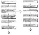
- FIGS. 4 and 5depict flow charts depicting operations performed by the roadway skeleton estimation system in estimating the skeleton of the roadway, FIG. 4 depicting operations in connection with a model in which the roadway is modeled as a circular arc and FIG. 5 depicting operations in connection with a model in which the roadway is modeled as a parabolic arc.
- FIG. 1schematically depicts a vehicle 10 moving on a roadway 11 and including a roadway skeleton estimation system 12 constructed in accordance with the invention.
- the vehicle 10may be any kind of vehicle 10 that may move on the roadway 11 , including, but not limited to automobiles, trucks, buses and the like.
- the roadway skeleton estimation system 12includes a camera 13 and a processor 14 .
- the camera 13is mounted on the vehicle 10 and is preferably pointed in a forward direction, that is, in the direction in which the vehicle would normally move, to record successive images as the vehicle moves over the roadway. Preferably as the camera 13 records each image, it will provide the image to the processor 14 .
- the processor 14will process information that it obtains from the successive images, possibly along with other information, such as information from the vehicle's speedometer (not separately shown) to estimate a roadway skeleton representing a portion of the roadway 11 ahead of the vehicle 10 .
- the processor 14may also be mounted in or on the vehicle 11 and may form part thereof.
- the roadway skeleton estimates generated by the processor 14may be used for a number of things, including, but not limited to autonomous driving by the vehicle, providing assistance in collision avoidance, and the like. Operations performed by the processor 14 in estimating the roadway skeleton will be described in connection with the flow chart depicted in FIG. 3 .
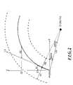
- the roadwayis modeled as a circular arc parallel to the XZ plane in three-dimensional space.
- the X (horizontal) and Y (vertical) axes of three-dimensional spacecorrespond to the “x” and “y” axes of the image plane of the images recorded by the camera 14 , and the Z axis is orthogonal to the image plane.
- the image planewill be the plane of the image after the image has been rectified to provide that the Z axis is parallel to the plane o the roadway 11 ;
- the Stein I patent applicationdescribes a methodology for rectifying the images to provide that the image plane will have a suitable orientation.
- the roadwayis modeled as a circular arc, and, with reference to FIG. 2 , that FIG. circular arc in the XZ plane representing the roadway, which will be referred to as the roadway's skeleton, is identified by reference numeral S.
- Two lane markings 20 L and 20 Rare also shown as dashed lines on opposite sides of the skeleton S.
- the distances R 1 and R 2 between the lane markings 20 L and 20 R and the skeleton Smay be the same, or they may differ.
- the center of the circular arcneed not be along the X axis, and, indeed will generally be at an angle ⁇ thereto.
- the circular arcis parameterized by three components, namely
- Z 1 and Z 2are three meters and thirty meters, respectively.
- value X 1represents the horizontal distance between the Z axis, specifically the point with coordinates ( 0 ,Z 1 ), and the point on skeleton S with coordinates (X 1 ,Z 1 ).
- the value X 2represents the horizontal distance between the points on line L 1 and circular arc comprising skeleton S at coordinate Z 2 .
- ⁇ 0tan - 1 ⁇ ( a b ) .
- the value for the radius Rcan be determined using equation (1).
- equations (4) through (6) and the coordinates (x,y) of each point in the image ⁇the coordinates (X,Y,Z) of points in three-dimensional space that are projected onto the image can be determined.
- the imagecan be warped from the (x,y) space to a ⁇ R, ⁇ space using equations (2) and (3).
- the image ⁇ in rectangular ((x,y)) coordinatescan be warped to ⁇ R, ⁇ space.
- the rangeis determined as follows. As noted above, warping the image of the roadway to R, ⁇ space effectively provides a warped image ⁇ ′ in which the roadway is straight, not curved.
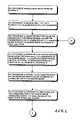
- An illustrative imageis depicted in FIG. 3 .
- roadway 30is divided into two regions, including a near region 31 and a more distant region 32 .
- the vertical coordinates of the picture elements, or “pixels,” that are subtended by the roadway in FIG. 3extends from ⁇ 120 to ⁇ 10
- the vertical coordinates of the near region 31extend from 120 to ⁇ 20.
- the bottom line of the warped image ⁇ ′maps to a line of width ⁇ X at distance Z, where
- the range of R, which is taken to be ⁇ R,is 3 ⁇ X.
- Z maxthe maximum value of Z for the roadway
- the operationsproceed in two phases.
- the processor 14performs a rough alignment using a straight road model.
- the areas of the image ⁇ ′are detected that appear to belong to road direction indicators, such as lane markings, tire marks, edges and so forth.
- the rough alignment generated during the first series of stepsis used, along with information in the image ⁇ ′ including both regions 31 and 32 to determine a higher-order model.
- only features found in the distant region 32 that are extensions of features found in the near region 31are utilized, which will ensure that non-roadway features, such as automobiles, that may be found in the distant region 32 will be ignored.
- the processor 14initially receives an image ⁇ from the camera 14 (step 200 ).
- the image ⁇is a projection of points in rectangular three-dimensional coordinates (X,Y,Z).
- the processor 14After receiving the image ⁇ , the processor 14 performs the first series of steps in connection with the near region 31 ( FIG. 3 ) of the roadway to generate a first-order model of the roadway.
- the processor 14will generate a warped image ⁇ ′, and generates a value for a cost function for each warped image ⁇ ′.
- the value of the cost functionwill represent a measure of the number of vertical features that are present in the warped image ⁇ ′. Since, for the warped image ⁇ ′ for which the roadway appears to be straightest, the number of vertical features that are present in the warped image ⁇ ′ will be largest, the processor 14 can select the value of the parameter X 1 that was used in generating the warped image ⁇ ′ associated with the largest cost function value as the appropriate value for parameter X 1 .
- the processor 14After the processor 14 receives the image ⁇ , it will select one, “i-th,” of the selected values for parameter X 1 (step 201 ) and using the selected value and the predetermined values for parameters X 2 and R, generate a warped image ⁇ ′ i , in which the image ⁇ is warped to the R, ⁇ space (step 202 ). Thereafter, the processor 14 will generate the cost function, as follows. The processor 14 initially generates a derivative image d ⁇ ′ along the horizontal (“x”) coordinate of the image ⁇ ′, the derivative representing the rate of change of image brightness, or intensity, as a function of the horizontal coordinate (step 203 ).
- the processor 14applies a non-linear function, such as a binary threshold or sigmoid function, to the derivative image d ⁇ ′, thereby to generate a normalized derivative image n(d ⁇ ′) (step 204 ).
- a non-linear functionsuch as a binary threshold or sigmoid function
- the processor 14for each column of pixels in the normalized derivative image n(d ⁇ ′) generated in step 204 , generates a sum of the pixel values of the pixels in the respective column (step 205 ), generates, for each column, the square of the sum generated for the column (step 206 ) and forms a sum of the squares generated in step 206 as the value of the cost function for the value of the parameter X 1 and the warped image ⁇ ′ generated therewith (step 207 ). In addition, the processor 14 determines, for each column, whether the value of the square exceeds a selected threshold (step 208 ).
- step 208the processor 14 will determine whether it has performed steps 202 through 208 in connection with all of the selected values for parameter X 1 (step 209 ). If the processor 14 makes a negative determination in connection with step 209 , it will return to step 202 to select another value for parameter X 1 and performs steps 203 through 209 in connection therewith.
- the processor 14will perform steps 202 through 209 in connection with each of the selected values for parameter X 1 to generate cost values therefor.
- the processor 14determines in step 209 that it has performed steps 202 through 209 in connection all of the selected values for parameter X 1 , it will sequence to step 209 to identify, among the cost function values generated in step 207 , the maximum cost function value (step 210 ).
- the parameter 14will determine the value of the parameter X 1 and the warped image ⁇ ′ associated with the maximum cost function value identified in step 209 (step 211 ). At this point the processor 14 will have completed the first phase, with the warped image ⁇ ′ comprising the rough alignment.
- the processor 14After completing the first phase, the processor 14 begins the second phase. In the second phase, the processor 14 performs operations similar to those described above in the first phase, except that
- step 212to determine the values for the respective parameters.
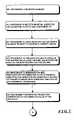
- the road skeleton Scan also be modeled as a parabolic arc.
- the major axis of the parabolic arcis along the X axis in three-dimensional space, which, as noted above, corresponds to the horizontal, or x, axis of the image ⁇ .
- Lane markingsare essentially horizontal translations from the skeleton, and therefore they can be modeled using equations of the same form as equation (16), and with the same values for coefficients “a” and “b” as that in the equation for the skeleton S, but different values for coefficient “c.” It will be appreciated that the value for coefficient “c” in the equations for the lane markings will indicate the horizontal displacement for the lane markings from the skeleton S for any point Z.
- the image ⁇can be warped to an image ⁇ ′, in which the skeleton is straight, as follows. If (x,y) are the coordinates of a point in image ⁇ that is a projection of a point with coordinates (X,Y,Z) in three-dimensional space
- Y⁇ Y h +dZ (18).
- Y his the height of the camera off the roadway and “d” is the pitch angle of the camera 14 relative to the horizontal axis Z.
- an overhead view (X,Z) of the skeleton of the roadwaythat is, a view in the XZ plane
- C,Zwarped view
- a cost functionis defined for the view (C,Z) whose value will be a maximum for the correct values of “a,” “b” and “d.”
- searching for the maximum of the cost function's valueis performed in two general phases, with a near region being used in the first phase, and a more extended region being used in the second phase.
- the value of the cost functionis determined as follows.
- image ⁇is warped to an image ⁇ ′.
- the image ⁇is an image of the roadway (and possibly other objects and features) in which the skeleton of the roadway is, in an overhead (X,Z) view, a parabolic arc.
- image ⁇ ′is an image of the roadway (and possibly other objects and features) in which the skeleton of the roadway may, in an overhead (C,Z) view, be a straight line, depending on the values for “a,” “b” and “d” that were used in the warping.
- the warped imageis projected onto the warped image's horizontal “x” axis by summing the pixel values in the respective columns.
- the derivative of the sums across the warped image's horizontal “x” axisis then determined, and a sum of the absolute values of the derivative across the warped image's horizontal “x” axis is generated, with that sum being the value of the cost function.
- the value of cost function valuewill be larger if the projection onto the warped image's horizontal projection is sharper, which will occur if there are more vertical features in the warped image ⁇ ′, and it would be possible to select the warped image ⁇ ′ for which the cost function value is greatest as the warped image ⁇ ′ in which the skeleton S of the roadway appears as a straight line. If there were no objects in the image ⁇ , and hence warped image ⁇ ′, other than the roadway 11 , this would be correct.
- the image ⁇is warped to provide warped images ⁇ ′ using a straight road model, that is, with value of coefficient “a” set to zero and the values of “b” and “d” may be zero or non-zero.
- a preliminary value for coefficient “b” and a value for pitch “d”are determined.
- image ⁇is again warped, to generate warped images ⁇ ′′ i , using selected values “a i ” for coefficient “a” and the preliminary value for coefficient “b” and the value for pitch “d” that were determined during the first phase.
- the cost function valuesare generated, and an assessment as to the warped image ⁇ ′′ i for which the skeleton S most approximates a straight line.
- the value “a i ” that was used in generating the warped image ⁇ ′′ i for which the skeleton S most approximates a straight lineis selected as the value for coefficient “a” for the model represented by equation (16).
- the value pitch “d” identified in the first phaseis selected as the pitch “d.”
- the value of coefficient “b” value for the model represented by equation (16)corresponds to the value ⁇ circumflex over (b) ⁇ which, as the coefficient of the linear term in the parabolic model for which the value “a i ” is identified as the coefficient “a” in the parabolic model, most approximates the straight line model, using the preliminary value for “b,” that was developed during the first phase.
- the processor 14After the processor 14 receives an image ⁇ (step 250 ), it will, in the first phase, select initial guess for the values for pitch “d” and coefficient “b” (step 251 ) and, using those values, warp the image ⁇ (step 252 ) thereby to generate a warped image ⁇ ′.
- the processor 14then, for each column of pixels in the warped image ⁇ ′, sums the pixel values for the pixels in the near region 31 in the column (step 253 ), generates values representing the derivative in the horizontal direction (step 254 ) and generates values that correspond to the absolute value of the derivative (step 255 ).
- portions of the warped image ⁇ ′ that contain, for example, edges or lane markingswill produce peaks in the absolute values generated in step 255 , since the edges and lane markings will correspond to fast transitions from dark-to-light or light-to-dark regions of the images.
- the processor 14then thresholds the absolute values generated in step 255 (step 256 ), that is, for any absolute value that is less than a predetermined threshold value, the processor 14 sets the absolute value to zero. For the absolute values that are above the threshold, the processor 14 then finds local maxima (step 257 ).
- peaks “p i ”typically correspond to lane markings in the warped image ⁇ ′, although some peaks p i may be caused by a strong edge that is not part of the roadway, such as an automobile a short distance ahead of the vehicle 10 .
- the set of points (d j ,b k i ) in a (d,b) plane that are associated with each peak p iform a line l i .
- the lines l i that are associated with features along the roadway, such as lane markings and tire tracks,will intersect at or near a point (d x ,b x ) in the (d,b) plane, and the processor 14 will identify that point and determine the appropriate values for coefficient “b” and pitch “d” as b x and d x , respectively.
- the processor 14determines a value for coefficient “a” using regions of the image including both the near region 31 and the far region 32 , generally emphasizing columns that are associated with or near the subset of peaks p i that it identified as being associated with features of the roadway.
- the processor 14selects a value of “a i ” (step 262 ) and warps the original image ⁇ to generate a warped image ⁇ ′′ i using the values “a i ” and “b x ” as coefficients “a” and “ ⁇ circumflex over (b) ⁇ l ” and value d x as the pitch “d” (step 263 ).
- the processor 14then projects a portion of the warped image ⁇ ′′ i , specifically the portion in the far region 32 , onto the warped image's horizontal axis by summing the pixel values of the pixels in each column in that region (step 264 ) and then generates the derivative of the sums along the horizontal axis (step 265 ).
- the processor 14will generate the absolute value of the derivative (step 266 ) and generate a value corresponding to the sum of the absolute values (step 267 ). It will be appreciated that, by performing steps 266 and 267 in connection only with columns that were determined in the first phase to be associated with features of the roadway 11 , the processor 14 will minimize contributions due to features that are not associated with the roadway, such as automobiles, which may otherwise unduly influence the result.
- the processor 14After performing steps 262 through 267 for the value “a i ” that was selected in step 262 , the processor 14 will determine whether it has selected all of the values “a i ” that were selected in step 260 (step 268 ), and, if not, return to step 262 to select another value “a i ” and perform steps 263 through 267 in connection therewith. The processor will perform steps 262 through 267 through a plurality of iterations until it has generated the sum of the absolute value of the derivative for all of the values “a i ” that were selected in step 260 .
- step 268When the processor 14 determines in step 268 that it has selected all of the values “a i ” that were selected in 260 , it will have generated a sum of the absolute value of the derivative for all of the values “a i ,” in which case it will sequence to step 269 .
- step 269the processor identifies the value “a i ” for which the sum is the largest (step 269 ).
- the correct parameters for the skeleton Sare, as the value of coefficient “a,” the value a i that was selected in step 269 , as the value of coefficient “b,” the value of ⁇ circumflex over (b) ⁇ that was generated for that value “a i ” in step 261 , and, as the pitch “d,” the value d x generated in the first phase.
- the inventionprovides a number of advantages.
- the inventionprovides a system for estimating the skeleton S of a roadway 11 for some distance ahead of a vehicle.
- Two specific methodologiesare described, one methodology using a model in which the roadway is modeled as a circular arc, and the other methodology using a model in which the roadway is modeled as a parabolic arc, in both methodologies requiring only one image, although it will be appreciated that the system can make use of a combination of these methodologies, and/or other methodologies. Determining the skeleton of a roadway for some distance ahead of a vehicle can be useful in connection with autonomous or assisted driving of the vehicle.
- a system in accordance with the inventioncan be constructed in whole or in part from special purpose hardware or a general purpose computer system, or any combination thereof, any portion of which may be controlled by a suitable program.
- Any programmay in whole or in part comprise part of or be stored on the system in a conventional manner, or it may in whole or in part be provided in to the system over a network or other mechanism for transferring information in a conventional manner.
- the systemmay be operated and/or otherwise controlled by means of information provided by an operator using operator input elements (not shown) which may be connected directly to the system or which may transfer the information to the system over a network or other mechanism for transferring information in a conventional manner.
Landscapes
- Engineering & Computer Science (AREA)
- Physics & Mathematics (AREA)
- General Physics & Mathematics (AREA)
- Theoretical Computer Science (AREA)
- Computer Vision & Pattern Recognition (AREA)
- Multimedia (AREA)
- Electromagnetism (AREA)
- Aviation & Aerospace Engineering (AREA)
- Radar, Positioning & Navigation (AREA)
- Remote Sensing (AREA)
- Automation & Control Theory (AREA)
- Image Processing (AREA)
- Traffic Control Systems (AREA)
- Image Analysis (AREA)
Abstract
Description
R2=a2+b2 (1).
In addition
X=(R+ΔR)cos(β+β0) (2)
and
Z=(R+ΔR)sin(β+β0) (3)
where
where X and Z are determined as above and Y is a function of the camera height Yh, the pitch “d” and the point's coordinate along the Z axis
Y=−Yh+dZ (6).
In equation (6), Yhis a positive value and is subtracted from “dZ” since the surface of the
R2=(X1−a)2+(Z1−b)2 (7)
and
R2=(X2−a)2+(Z2−b)2 (8)
and given the relation in equation (1), solving for “a” and “b”
After values for “a” and “b,” the “X” and “Z” components of the center of the circular arc S in the XZ plane, the radius R can be determined using equation (1).
and, if, as shown in
The range of R, which is taken to be ΔR, is 3ΔX.
X=aZ2+bZ+c (16),
where coefficients “a,” “b” and “c” are constants. The
If a point in the image is a projection of a point the roadway,
Y=−Yh+dZ (18).
where, as above (see equation (6)), Yhis the height of the camera off the roadway and “d” is the pitch angle of the
Claims (26)
Priority Applications (1)
| Application Number | Priority Date | Filing Date | Title |
|---|---|---|---|
| US09/834,736US7151996B2 (en) | 2000-04-14 | 2001-04-14 | System and method for generating a model of the path of a roadway from an image recorded by a camera |
Applications Claiming Priority (2)
| Application Number | Priority Date | Filing Date | Title |
|---|---|---|---|
| US19739300P | 2000-04-14 | 2000-04-14 | |
| US09/834,736US7151996B2 (en) | 2000-04-14 | 2001-04-14 | System and method for generating a model of the path of a roadway from an image recorded by a camera |
Publications (2)
| Publication Number | Publication Date |
|---|---|
| US20030040864A1 US20030040864A1 (en) | 2003-02-27 |
| US7151996B2true US7151996B2 (en) | 2006-12-19 |
Family
ID=22729225
Family Applications (1)
| Application Number | Title | Priority Date | Filing Date |
|---|---|---|---|
| US09/834,736Expired - LifetimeUS7151996B2 (en) | 2000-04-14 | 2001-04-14 | System and method for generating a model of the path of a roadway from an image recorded by a camera |
Country Status (3)
| Country | Link |
|---|---|
| US (1) | US7151996B2 (en) |
| AU (1) | AU2001253619A1 (en) |
| WO (1) | WO2001080068A1 (en) |
Cited By (75)
| Publication number | Priority date | Publication date | Assignee | Title |
|---|---|---|---|---|
| US20040240710A1 (en)* | 2001-08-07 | 2004-12-02 | Ulrich Lages | Method for determining a model roadway |
| US20050268137A1 (en)* | 2003-01-21 | 2005-12-01 | Nextio Inc. | Method and apparatus for a shared I/O network interface controller |
| US20060151223A1 (en)* | 2002-11-16 | 2006-07-13 | Peter Knoll | Device and method for improving visibility in a motor vehicle |
| US20080036576A1 (en)* | 2006-05-31 | 2008-02-14 | Mobileye Technologies Ltd. | Fusion of far infrared and visible images in enhanced obstacle detection in automotive applications |
| US20080043099A1 (en)* | 2006-08-10 | 2008-02-21 | Mobileye Technologies Ltd. | Symmetric filter patterns for enhanced performance of single and concurrent driver assistance applications |
| US20090010482A1 (en)* | 2004-06-02 | 2009-01-08 | Toyota Jidosha Kabushiki Kaisha | Diagrammatizing Apparatus |
| US20090084173A1 (en)* | 2007-09-27 | 2009-04-02 | Caterpillar Inc. | Automated lost load response system |
| US20090202109A1 (en)* | 2008-02-13 | 2009-08-13 | Caterpillar Inc. | Terrain map updating system |
| US20100014714A1 (en)* | 2008-07-18 | 2010-01-21 | Gm Global Technology Operations, Inc. | Camera-based lane marker detection |
| US20100121566A1 (en)* | 2008-11-07 | 2010-05-13 | Dhiraj Joshi | Generating photogenic routes from starting to destination locations |
| US20100157061A1 (en)* | 2008-12-24 | 2010-06-24 | Igor Katsman | Device and method for handheld device based vehicle monitoring and driver assistance |
| EP2383679A1 (en) | 2006-12-06 | 2011-11-02 | Mobileye Technologies Limited | Detecting and recognizing traffic signs |
| US8099213B2 (en) | 2008-07-18 | 2012-01-17 | GM Global Technology Operations LLC | Road-edge detection |
| US8194927B2 (en) | 2008-07-18 | 2012-06-05 | GM Global Technology Operations LLC | Road-lane marker detection using light-based sensing technology |
| WO2012101430A1 (en)* | 2011-01-25 | 2012-08-02 | Trw Limited | Method of processing images and apparatus |
| EP2574958A1 (en) | 2011-09-28 | 2013-04-03 | Honda Research Institute Europe GmbH | Road-terrain detection method and system for driver assistance systems |
| US8818042B2 (en) | 2004-04-15 | 2014-08-26 | Magna Electronics Inc. | Driver assistance system for vehicle |
| US8842176B2 (en) | 1996-05-22 | 2014-09-23 | Donnelly Corporation | Automatic vehicle exterior light control |
| US8917169B2 (en) | 1993-02-26 | 2014-12-23 | Magna Electronics Inc. | Vehicular vision system |
| US8977008B2 (en) | 2004-09-30 | 2015-03-10 | Donnelly Corporation | Driver assistance system for vehicle |
| US8993951B2 (en) | 1996-03-25 | 2015-03-31 | Magna Electronics Inc. | Driver assistance system for a vehicle |
| US9014904B2 (en) | 2004-12-23 | 2015-04-21 | Magna Electronics Inc. | Driver assistance system for vehicle |
| EP2899669A1 (en) | 2014-01-22 | 2015-07-29 | Honda Research Institute Europe GmbH | Lane relative position estimation method and system for driver assistance systems |
| US9171217B2 (en) | 2002-05-03 | 2015-10-27 | Magna Electronics Inc. | Vision system for vehicle |
| US9191574B2 (en) | 2001-07-31 | 2015-11-17 | Magna Electronics Inc. | Vehicular vision system |
| US9205776B2 (en) | 2013-05-21 | 2015-12-08 | Magna Electronics Inc. | Vehicle vision system using kinematic model of vehicle motion |
| US9319637B2 (en) | 2012-03-27 | 2016-04-19 | Magna Electronics Inc. | Vehicle vision system with lens pollution detection |
| US9357208B2 (en) | 2011-04-25 | 2016-05-31 | Magna Electronics Inc. | Method and system for dynamically calibrating vehicular cameras |
| US9436880B2 (en) | 1999-08-12 | 2016-09-06 | Magna Electronics Inc. | Vehicle vision system |
| US9445057B2 (en) | 2013-02-20 | 2016-09-13 | Magna Electronics Inc. | Vehicle vision system with dirt detection |
| US9440535B2 (en) | 2006-08-11 | 2016-09-13 | Magna Electronics Inc. | Vision system for vehicle |
| US9483700B1 (en) | 2015-05-13 | 2016-11-01 | Honda Motor Co., Ltd. | System and method for lane vehicle localization with lane marking detection and likelihood scoring |
| US9491450B2 (en) | 2011-08-01 | 2016-11-08 | Magna Electronic Inc. | Vehicle camera alignment system |
| US9491451B2 (en) | 2011-11-15 | 2016-11-08 | Magna Electronics Inc. | Calibration system and method for vehicular surround vision system |
| US9487235B2 (en) | 2014-04-10 | 2016-11-08 | Magna Electronics Inc. | Vehicle control system with adaptive wheel angle correction |
| US9508014B2 (en) | 2013-05-06 | 2016-11-29 | Magna Electronics Inc. | Vehicular multi-camera vision system |
| US9547795B2 (en) | 2011-04-25 | 2017-01-17 | Magna Electronics Inc. | Image processing method for detecting objects using relative motion |
| US9550455B2 (en) | 2012-04-25 | 2017-01-24 | Gentex Corporation | Multi-focus optical system |
| US9563951B2 (en) | 2013-05-21 | 2017-02-07 | Magna Electronics Inc. | Vehicle vision system with targetless camera calibration |
| US9688200B2 (en) | 2013-03-04 | 2017-06-27 | Magna Electronics Inc. | Calibration system and method for multi-camera vision system |
| US9707892B2 (en) | 2012-04-25 | 2017-07-18 | Gentex Corporation | Multi-focus optical system |
| US9707896B2 (en) | 2012-10-15 | 2017-07-18 | Magna Electronics Inc. | Vehicle camera lens dirt protection via air flow |
| US9723272B2 (en) | 2012-10-05 | 2017-08-01 | Magna Electronics Inc. | Multi-camera image stitching calibration system |
| US9762880B2 (en) | 2011-12-09 | 2017-09-12 | Magna Electronics Inc. | Vehicle vision system with customized display |
| US9819841B1 (en)* | 2015-04-17 | 2017-11-14 | Altera Corporation | Integrated circuits with optical flow computation circuitry |
| US9834153B2 (en) | 2011-04-25 | 2017-12-05 | Magna Electronics Inc. | Method and system for dynamically calibrating vehicular cameras |
| US9863928B1 (en) | 2013-03-20 | 2018-01-09 | United Parcel Service Of America, Inc. | Road condition detection system |
| US9900522B2 (en) | 2010-12-01 | 2018-02-20 | Magna Electronics Inc. | System and method of establishing a multi-camera image using pixel remapping |
| US9916660B2 (en) | 2015-01-16 | 2018-03-13 | Magna Electronics Inc. | Vehicle vision system with calibration algorithm |
| US9959595B2 (en) | 2010-09-21 | 2018-05-01 | Mobileye Vision Technologies Ltd. | Dense structure from motion |
| WO2018081807A2 (en) | 2016-10-31 | 2018-05-03 | Mobileye Vision Technologies Ltd. | Systems and methods for navigating lane merges and lane splits |
| US9972100B2 (en) | 2007-08-17 | 2018-05-15 | Magna Electronics Inc. | Vehicular imaging system comprising an imaging device with a single image sensor and image processor for determining a totally blocked state or partially blocked state of the single image sensor as well as an automatic correction for misalignment of the imaging device |
| US9969389B2 (en)* | 2016-05-03 | 2018-05-15 | Ford Global Technologies, Llc | Enhanced vehicle operation |
| US10071687B2 (en) | 2011-11-28 | 2018-09-11 | Magna Electronics Inc. | Vision system for vehicle |
| US10078788B2 (en) | 2010-09-21 | 2018-09-18 | Mobileye Vision Technologies Ltd. | Barrier and guardrail detection using a single camera |
| US10179543B2 (en) | 2013-02-27 | 2019-01-15 | Magna Electronics Inc. | Multi-camera dynamic top view vision system |
| US10187590B2 (en) | 2015-10-27 | 2019-01-22 | Magna Electronics Inc. | Multi-camera vehicle vision system with image gap fill |
| US10300859B2 (en) | 2016-06-10 | 2019-05-28 | Magna Electronics Inc. | Multi-sensor interior mirror device with image adjustment |
| US10452076B2 (en) | 2017-01-04 | 2019-10-22 | Magna Electronics Inc. | Vehicle vision system with adjustable computation and data compression |
| US10457209B2 (en) | 2012-02-22 | 2019-10-29 | Magna Electronics Inc. | Vehicle vision system with multi-paned view |
| US10493916B2 (en) | 2012-02-22 | 2019-12-03 | Magna Electronics Inc. | Vehicle camera system with image manipulation |
| US10750119B2 (en) | 2016-10-17 | 2020-08-18 | Magna Electronics Inc. | Vehicle camera LVDS repeater |
| US10776635B2 (en) | 2010-09-21 | 2020-09-15 | Mobileye Vision Technologies Ltd. | Monocular cued detection of three-dimensional structures from depth images |
| US10793067B2 (en) | 2011-07-26 | 2020-10-06 | Magna Electronics Inc. | Imaging system for vehicle |
| US10830642B2 (en) | 2008-01-15 | 2020-11-10 | Mobileye Vision Technologies Ltd. | Detection and classification of light sources using a diffraction grating |
| US10946799B2 (en) | 2015-04-21 | 2021-03-16 | Magna Electronics Inc. | Vehicle vision system with overlay calibration |
| US11091171B2 (en) | 2015-09-25 | 2021-08-17 | Slingshot Iot Llc | Controlling driving modes of self-driving vehicles |
| US11228700B2 (en) | 2015-10-07 | 2022-01-18 | Magna Electronics Inc. | Vehicle vision system camera with adaptive field of view |
| US11277558B2 (en) | 2016-02-01 | 2022-03-15 | Magna Electronics Inc. | Vehicle vision system with master-slave camera configuration |
| US11433809B2 (en) | 2016-02-02 | 2022-09-06 | Magna Electronics Inc. | Vehicle vision system with smart camera video output |
| US11877054B2 (en) | 2011-09-21 | 2024-01-16 | Magna Electronics Inc. | Vehicular vision system using image data transmission and power supply via a coaxial cable |
| US12137143B1 (en) | 2019-04-26 | 2024-11-05 | Samsara Inc. | Event detection system |
| US12165336B1 (en) | 2019-04-26 | 2024-12-10 | Samsara Inc. | Machine-learned model based event detection |
| US12375578B1 (en) | 2020-02-20 | 2025-07-29 | Samsara Inc. | Device arrangement for deriving a communication data scheme |
| US12391256B1 (en) | 2019-04-26 | 2025-08-19 | Samsara Inc. | Baseline event detection system |
Families Citing this family (15)
| Publication number | Priority date | Publication date | Assignee | Title |
|---|---|---|---|---|
| US8164628B2 (en) | 2006-01-04 | 2012-04-24 | Mobileye Technologies Ltd. | Estimating distance to an object using a sequence of images recorded by a monocular camera |
| US9886794B2 (en) | 2012-06-05 | 2018-02-06 | Apple Inc. | Problem reporting in maps |
| US10176633B2 (en) | 2012-06-05 | 2019-01-08 | Apple Inc. | Integrated mapping and navigation application |
| US8965696B2 (en) | 2012-06-05 | 2015-02-24 | Apple Inc. | Providing navigation instructions while operating navigation application in background |
| US9482296B2 (en) | 2012-06-05 | 2016-11-01 | Apple Inc. | Rendering road signs during navigation |
| US8983778B2 (en)* | 2012-06-05 | 2015-03-17 | Apple Inc. | Generation of intersection information by a mapping service |
| US9418672B2 (en) | 2012-06-05 | 2016-08-16 | Apple Inc. | Navigation application with adaptive instruction text |
| US9230556B2 (en) | 2012-06-05 | 2016-01-05 | Apple Inc. | Voice instructions during navigation |
| US9997069B2 (en) | 2012-06-05 | 2018-06-12 | Apple Inc. | Context-aware voice guidance |
| US9747507B2 (en)* | 2013-12-19 | 2017-08-29 | Texas Instruments Incorporated | Ground plane detection |
| WO2015189847A1 (en)* | 2014-06-10 | 2015-12-17 | Mobileye Vision Technologies Ltd. | Top-down refinement in lane marking navigation |
| EP4254383A3 (en) | 2014-08-18 | 2023-12-20 | Mobileye Vision Technologies Ltd. | Recognition and prediction of lane constraints |
| JP6449627B2 (en)* | 2014-11-25 | 2019-01-09 | 株式会社Soken | Traveling line recognition device |
| KR102296520B1 (en)* | 2020-12-18 | 2021-09-01 | 주식회사 카비 | Method of detecting curved lane through path estimation by monocular vision based camera |
| FR3120690B1 (en)* | 2021-03-15 | 2023-02-10 | Psa Automobiles Sa | Method and device for determining the reliability of a base definition cartography. |
Citations (37)
| Publication number | Priority date | Publication date | Assignee | Title |
|---|---|---|---|---|
| US4819169A (en)* | 1986-09-24 | 1989-04-04 | Nissan Motor Company, Limited | System and method for calculating movement direction and position of an unmanned vehicle |
| US4910786A (en)* | 1985-09-30 | 1990-03-20 | Eichel Paul H | Method of detecting intensity edge paths |
| CA2047811A1 (en)* | 1990-07-31 | 1992-02-01 | Jean-Yves Dufour | Method and device for real time localization of rectilinear contours in a digitized image, particularly for pattern recognition in scene analysis processings |
| WO1992005518A1 (en)* | 1990-09-17 | 1992-04-02 | Teknekron Communications Systems, Inc. | A method and an apparatus for generating a video binary signal for a video image having a matrix of pixels |
| US5245422A (en)* | 1991-06-28 | 1993-09-14 | Zexel Corporation | System and method for automatically steering a vehicle within a lane in a road |
| JPH06107096A (en) | 1992-09-25 | 1994-04-19 | Yazaki Corp | Forward monitoring method for vehicles |
| US5446549A (en)* | 1993-01-14 | 1995-08-29 | The United States Of America As Represented By The Secretary Of The Navy | Method and apparatus for noncontact surface contour measurement |
| US5473364A (en) | 1994-06-03 | 1995-12-05 | David Sarnoff Research Center, Inc. | Video technique for indicating moving objects from a movable platform |
| US5515448A (en) | 1992-07-28 | 1996-05-07 | Yazaki Corporation | Distance measuring apparatus of a target tracking type |
| US5521633A (en) | 1992-09-25 | 1996-05-28 | Yazaki Corporation | Motor vehicle obstacle monitoring system using optical flow processing |
| US5529138A (en) | 1993-01-22 | 1996-06-25 | Shaw; David C. H. | Vehicle collision avoidance system |
| US5642093A (en) | 1995-01-27 | 1997-06-24 | Fuji Jukogyo Kabushiki Kaisha | Warning system for vehicle |
| US5646612A (en) | 1995-02-09 | 1997-07-08 | Daewoo Electronics Co., Ltd. | Method for avoiding collision of vehicle and apparatus for performing the same |
| US5717781A (en)* | 1992-12-21 | 1998-02-10 | Johnson & Johnson Vision Products, Inc. | Ophthalmic lens inspection method and apparatus |
| US5809161A (en) | 1992-03-20 | 1998-09-15 | Commonwealth Scientific And Industrial Research Organisation | Vehicle monitoring system |
| US5850254A (en) | 1994-07-05 | 1998-12-15 | Hitachi, Ltd. | Imaging system for a vehicle which compares a reference image which includes a mark which is fixed to said vehicle to subsequent images |
| US5862245A (en)* | 1995-06-16 | 1999-01-19 | Alcatel Alsthom Compagnie Generale D'electricite | Method of extracting contours using a combined active contour and starter/guide approach |
| US5913375A (en) | 1995-08-31 | 1999-06-22 | Honda Giken Kogyo Kabushiki Kaisha | Vehicle steering force correction system |
| US5974521A (en)* | 1993-12-12 | 1999-10-26 | Neomagic Israel Ltd. | Apparatus and method for signal processing |
| US5987174A (en)* | 1995-04-26 | 1999-11-16 | Hitachi, Ltd. | Image processing apparatus for vehicles |
| US5987152A (en) | 1994-07-06 | 1999-11-16 | Volkswagen Ag | Method for measuring visibility from a moving vehicle |
| US6097839A (en)* | 1997-03-10 | 2000-08-01 | Intermec Ip Corporation | Method and apparatus for automatic discriminating and locating patterns such as finder patterns, or portions thereof, in machine-readable symbols |
| US6128046A (en)* | 1995-05-12 | 2000-10-03 | Sony Corporation | Key signal generating apparatus and picture synthesis apparatus, and key signal generating method and picture synthesis method |
| US6130706A (en)* | 1998-03-25 | 2000-10-10 | Lucent Technologies Inc. | Process for determining vehicle dynamics |
| US6161071A (en)* | 1999-03-12 | 2000-12-12 | Navigation Technologies Corporation | Method and system for an in-vehicle computing architecture |
| JP2001034769A (en) | 1999-07-26 | 2001-02-09 | Pioneer Electronic Corp | Device and method for image processing and navigation device |
| US6246961B1 (en) | 1998-06-09 | 2001-06-12 | Yazaki Corporation | Collision alarm method and apparatus for vehicles |
| US6313840B1 (en)* | 1997-04-18 | 2001-11-06 | Adobe Systems Incorporated | Smooth shading of objects on display devices |
| US6424430B1 (en)* | 1998-04-06 | 2002-07-23 | Adobe Systems Incorporated | Rendering of objects on graphical rendering devices as clipped images |
| JP2002367059A (en)* | 2001-06-13 | 2002-12-20 | Mbr:Kk | Transfer type security system |
| US6501848B1 (en)* | 1996-06-19 | 2002-12-31 | University Technology Corporation | Method and apparatus for three-dimensional reconstruction of coronary vessels from angiographic images and analytical techniques applied thereto |
| US6505107B2 (en)* | 2000-06-20 | 2003-01-07 | Hitachi, Ltd. | Vehicle travel control apparatus |
| US6526352B1 (en)* | 2001-07-19 | 2003-02-25 | Intelligent Technologies International, Inc. | Method and arrangement for mapping a road |
| US6560529B1 (en)* | 1998-09-15 | 2003-05-06 | Robert Bosch Gmbh | Method and device for traffic sign recognition and navigation |
| US20040122587A1 (en)* | 2002-12-18 | 2004-06-24 | Hiroyuki Kanemitsu | Driving support system, driving support apparatus and driving support method |
| US20050060069A1 (en)* | 1997-10-22 | 2005-03-17 | Breed David S. | Method and system for controlling a vehicle |
| US20050137786A1 (en)* | 1997-10-22 | 2005-06-23 | Intelligent Technologies International Inc. | Communication method and arrangement |
- 2001
- 2001-04-14WOPCT/US2001/012527patent/WO2001080068A1/enactiveApplication Filing
- 2001-04-14AUAU2001253619Apatent/AU2001253619A1/ennot_activeAbandoned
- 2001-04-14USUS09/834,736patent/US7151996B2/ennot_activeExpired - Lifetime
Patent Citations (44)
| Publication number | Priority date | Publication date | Assignee | Title |
|---|---|---|---|---|
| US4910786A (en)* | 1985-09-30 | 1990-03-20 | Eichel Paul H | Method of detecting intensity edge paths |
| US4819169A (en)* | 1986-09-24 | 1989-04-04 | Nissan Motor Company, Limited | System and method for calculating movement direction and position of an unmanned vehicle |
| US5233670A (en)* | 1990-07-31 | 1993-08-03 | Thomson Trt Defense | Method and device for the real-time localization of rectilinear contours in a digitized image, notably for shape recognition in scene analysis processing |
| EP0473476A1 (en)* | 1990-07-31 | 1992-03-04 | Thomson-Trt Defense | Straight edge real-time localisation device and process in a numerical image, especially for pattern recognition in a scene analysis process |
| CA2047811A1 (en)* | 1990-07-31 | 1992-02-01 | Jean-Yves Dufour | Method and device for real time localization of rectilinear contours in a digitized image, particularly for pattern recognition in scene analysis processings |
| WO1992005518A1 (en)* | 1990-09-17 | 1992-04-02 | Teknekron Communications Systems, Inc. | A method and an apparatus for generating a video binary signal for a video image having a matrix of pixels |
| US5189710A (en)* | 1990-09-17 | 1993-02-23 | Teknekron Communications Systems, Inc. | Method and an apparatus for generating a video binary signal for a video image having a matrix of pixels |
| US5245422A (en)* | 1991-06-28 | 1993-09-14 | Zexel Corporation | System and method for automatically steering a vehicle within a lane in a road |
| US5809161A (en) | 1992-03-20 | 1998-09-15 | Commonwealth Scientific And Industrial Research Organisation | Vehicle monitoring system |
| US5515448A (en) | 1992-07-28 | 1996-05-07 | Yazaki Corporation | Distance measuring apparatus of a target tracking type |
| JPH06107096A (en) | 1992-09-25 | 1994-04-19 | Yazaki Corp | Forward monitoring method for vehicles |
| US5521633A (en) | 1992-09-25 | 1996-05-28 | Yazaki Corporation | Motor vehicle obstacle monitoring system using optical flow processing |
| US5717781A (en)* | 1992-12-21 | 1998-02-10 | Johnson & Johnson Vision Products, Inc. | Ophthalmic lens inspection method and apparatus |
| US5446549A (en)* | 1993-01-14 | 1995-08-29 | The United States Of America As Represented By The Secretary Of The Navy | Method and apparatus for noncontact surface contour measurement |
| US5529138A (en) | 1993-01-22 | 1996-06-25 | Shaw; David C. H. | Vehicle collision avoidance system |
| US6460127B1 (en)* | 1993-12-12 | 2002-10-01 | Neomagic Israel Ltd. | Apparatus and method for signal processing |
| US5974521A (en)* | 1993-12-12 | 1999-10-26 | Neomagic Israel Ltd. | Apparatus and method for signal processing |
| US5473364A (en) | 1994-06-03 | 1995-12-05 | David Sarnoff Research Center, Inc. | Video technique for indicating moving objects from a movable platform |
| US5850254A (en) | 1994-07-05 | 1998-12-15 | Hitachi, Ltd. | Imaging system for a vehicle which compares a reference image which includes a mark which is fixed to said vehicle to subsequent images |
| US5987152A (en) | 1994-07-06 | 1999-11-16 | Volkswagen Ag | Method for measuring visibility from a moving vehicle |
| US5642093A (en) | 1995-01-27 | 1997-06-24 | Fuji Jukogyo Kabushiki Kaisha | Warning system for vehicle |
| US5646612A (en) | 1995-02-09 | 1997-07-08 | Daewoo Electronics Co., Ltd. | Method for avoiding collision of vehicle and apparatus for performing the same |
| US5987174A (en)* | 1995-04-26 | 1999-11-16 | Hitachi, Ltd. | Image processing apparatus for vehicles |
| US6128046A (en)* | 1995-05-12 | 2000-10-03 | Sony Corporation | Key signal generating apparatus and picture synthesis apparatus, and key signal generating method and picture synthesis method |
| US5862245A (en)* | 1995-06-16 | 1999-01-19 | Alcatel Alsthom Compagnie Generale D'electricite | Method of extracting contours using a combined active contour and starter/guide approach |
| US5913375A (en) | 1995-08-31 | 1999-06-22 | Honda Giken Kogyo Kabushiki Kaisha | Vehicle steering force correction system |
| US6501848B1 (en)* | 1996-06-19 | 2002-12-31 | University Technology Corporation | Method and apparatus for three-dimensional reconstruction of coronary vessels from angiographic images and analytical techniques applied thereto |
| US6097839A (en)* | 1997-03-10 | 2000-08-01 | Intermec Ip Corporation | Method and apparatus for automatic discriminating and locating patterns such as finder patterns, or portions thereof, in machine-readable symbols |
| US6313840B1 (en)* | 1997-04-18 | 2001-11-06 | Adobe Systems Incorporated | Smooth shading of objects on display devices |
| US20050137786A1 (en)* | 1997-10-22 | 2005-06-23 | Intelligent Technologies International Inc. | Communication method and arrangement |
| US20050060069A1 (en)* | 1997-10-22 | 2005-03-17 | Breed David S. | Method and system for controlling a vehicle |
| US6130706A (en)* | 1998-03-25 | 2000-10-10 | Lucent Technologies Inc. | Process for determining vehicle dynamics |
| US6424430B1 (en)* | 1998-04-06 | 2002-07-23 | Adobe Systems Incorporated | Rendering of objects on graphical rendering devices as clipped images |
| US6246961B1 (en) | 1998-06-09 | 2001-06-12 | Yazaki Corporation | Collision alarm method and apparatus for vehicles |
| US6560529B1 (en)* | 1998-09-15 | 2003-05-06 | Robert Bosch Gmbh | Method and device for traffic sign recognition and navigation |
| US6161071A (en)* | 1999-03-12 | 2000-12-12 | Navigation Technologies Corporation | Method and system for an in-vehicle computing architecture |
| US20030065432A1 (en)* | 1999-03-12 | 2003-04-03 | Valerie Shuman | Method and system for an in-vehicle computing architecture |
| US6675081B2 (en)* | 1999-03-12 | 2004-01-06 | Navigation Technologies Corp. | Method and system for an in-vehicle computing architecture |
| US6353785B1 (en)* | 1999-03-12 | 2002-03-05 | Navagation Technologies Corp. | Method and system for an in-vehicle computer architecture |
| JP2001034769A (en) | 1999-07-26 | 2001-02-09 | Pioneer Electronic Corp | Device and method for image processing and navigation device |
| US6505107B2 (en)* | 2000-06-20 | 2003-01-07 | Hitachi, Ltd. | Vehicle travel control apparatus |
| JP2002367059A (en)* | 2001-06-13 | 2002-12-20 | Mbr:Kk | Transfer type security system |
| US6526352B1 (en)* | 2001-07-19 | 2003-02-25 | Intelligent Technologies International, Inc. | Method and arrangement for mapping a road |
| US20040122587A1 (en)* | 2002-12-18 | 2004-06-24 | Hiroyuki Kanemitsu | Driving support system, driving support apparatus and driving support method |
Non-Patent Citations (10)
| Title |
|---|
| A. L. Maganto et al. "A Monocular Vision System For Autonomous Vehicle Guidance," 2000 Int'l Conf On Image Processing, pp. 236-239, no date. |
| G. P. Stein et al. "A Robust Method For Computing Vehicle Ego-Motion," Proc. IEEE Intelligent Vehicles Symposium 2000, pp. 362-368, Oct. 3-5, 2000. |
| H. Frohn et al. "VISOCAR: An Autonomous Industrial Transport Vehicle Guided By Visual Navigation," 1989 IEEE Int'l Conf on Robotics and Automation, 1989, May 1989, pp. 1155-1159. |
| Li, Quing et al., Lane boundary detection using an adaptive randomized Hough transform, Conference Procedings v5 2004, Fifth World Congress on Intelligent Control and Automation, date: Jun. 15, 2004.* |
| R. Gregor et al, "EMS-Vision: A Perceptual System For Autonomous Vehicles," Proc IEEE Intelligent Vehicles Symposium 2000, pp. 52-57, Oct. 3-5, 2000. |
| R. Janssen et al "Hybrid Approach For Traffic Sign Recognition," Intelligent Vehicles '93 Symposium, 1993, pp. 390-395, no date. |
| S. Estable et al. "A Real-Time Traffic Sign Recognition System," Proc Intelligent Vehicles '94 Symposium, pp. 213-218, no date. |
| S. K. Gehrig et al. "A Trajectory Based Approach For The Lateral Control Of Car Following Systems," 1998 IEEE Int'l Conf on Systems, Man and Cybernetics, 1998, vol. 4, pp. 3596-3601. |
| Tian, Aliling et al., Three-dimensional profile measurement of objects with spatially isolated surfaces by modified temporal phase unwrapping, Journal of Xi'An Jiaotong university, vol. 36 No. 11, Nov. 2004, pp. 1196-1198.* |
| W. J. Gillner, "Motion Based Vehicle Detection On Motorways," Proc Intelligent Vehicles '95 Symposium, 1995, pp. 483-487, no date. |
Cited By (212)
| Publication number | Priority date | Publication date | Assignee | Title |
|---|---|---|---|---|
| US8917169B2 (en) | 1993-02-26 | 2014-12-23 | Magna Electronics Inc. | Vehicular vision system |
| US8993951B2 (en) | 1996-03-25 | 2015-03-31 | Magna Electronics Inc. | Driver assistance system for a vehicle |
| US9131120B2 (en) | 1996-05-22 | 2015-09-08 | Magna Electronics Inc. | Multi-camera vision system for a vehicle |
| US8842176B2 (en) | 1996-05-22 | 2014-09-23 | Donnelly Corporation | Automatic vehicle exterior light control |
| US9436880B2 (en) | 1999-08-12 | 2016-09-06 | Magna Electronics Inc. | Vehicle vision system |
| US9834142B2 (en) | 2001-07-31 | 2017-12-05 | Magna Electronics Inc. | Driving assist system for vehicle |
| US9191574B2 (en) | 2001-07-31 | 2015-11-17 | Magna Electronics Inc. | Vehicular vision system |
| US10046702B2 (en) | 2001-07-31 | 2018-08-14 | Magna Electronics Inc. | Control system for vehicle |
| US9376060B2 (en) | 2001-07-31 | 2016-06-28 | Magna Electronics Inc. | Driver assist system for vehicle |
| US10611306B2 (en) | 2001-07-31 | 2020-04-07 | Magna Electronics Inc. | Video processor module for vehicle |
| US9656608B2 (en) | 2001-07-31 | 2017-05-23 | Magna Electronics Inc. | Driver assist system for vehicle |
| US20040240710A1 (en)* | 2001-08-07 | 2004-12-02 | Ulrich Lages | Method for determining a model roadway |
| US9171217B2 (en) | 2002-05-03 | 2015-10-27 | Magna Electronics Inc. | Vision system for vehicle |
| US10351135B2 (en) | 2002-05-03 | 2019-07-16 | Magna Electronics Inc. | Vehicular control system using cameras and radar sensor |
| US9834216B2 (en) | 2002-05-03 | 2017-12-05 | Magna Electronics Inc. | Vehicular control system using cameras and radar sensor |
| US9555803B2 (en) | 2002-05-03 | 2017-01-31 | Magna Electronics Inc. | Driver assistance system for vehicle |
| US11203340B2 (en) | 2002-05-03 | 2021-12-21 | Magna Electronics Inc. | Vehicular vision system using side-viewing camera |
| US9643605B2 (en) | 2002-05-03 | 2017-05-09 | Magna Electronics Inc. | Vision system for vehicle |
| US10118618B2 (en) | 2002-05-03 | 2018-11-06 | Magna Electronics Inc. | Vehicular control system using cameras and radar sensor |
| US10683008B2 (en) | 2002-05-03 | 2020-06-16 | Magna Electronics Inc. | Vehicular driving assist system using forward-viewing camera |
| US20060151223A1 (en)* | 2002-11-16 | 2006-07-13 | Peter Knoll | Device and method for improving visibility in a motor vehicle |
| US20050268137A1 (en)* | 2003-01-21 | 2005-12-01 | Nextio Inc. | Method and apparatus for a shared I/O network interface controller |
| US10462426B2 (en) | 2004-04-15 | 2019-10-29 | Magna Electronics Inc. | Vehicular control system |
| US9736435B2 (en) | 2004-04-15 | 2017-08-15 | Magna Electronics Inc. | Vision system for vehicle |
| US10110860B1 (en) | 2004-04-15 | 2018-10-23 | Magna Electronics Inc. | Vehicular control system |
| US11847836B2 (en) | 2004-04-15 | 2023-12-19 | Magna Electronics Inc. | Vehicular control system with road curvature determination |
| US9609289B2 (en) | 2004-04-15 | 2017-03-28 | Magna Electronics Inc. | Vision system for vehicle |
| US9008369B2 (en) | 2004-04-15 | 2015-04-14 | Magna Electronics Inc. | Vision system for vehicle |
| US10015452B1 (en) | 2004-04-15 | 2018-07-03 | Magna Electronics Inc. | Vehicular control system |
| US9428192B2 (en) | 2004-04-15 | 2016-08-30 | Magna Electronics Inc. | Vision system for vehicle |
| US11503253B2 (en) | 2004-04-15 | 2022-11-15 | Magna Electronics Inc. | Vehicular control system with traffic lane detection |
| US10187615B1 (en) | 2004-04-15 | 2019-01-22 | Magna Electronics Inc. | Vehicular control system |
| US10306190B1 (en) | 2004-04-15 | 2019-05-28 | Magna Electronics Inc. | Vehicular control system |
| US9191634B2 (en) | 2004-04-15 | 2015-11-17 | Magna Electronics Inc. | Vision system for vehicle |
| US8818042B2 (en) | 2004-04-15 | 2014-08-26 | Magna Electronics Inc. | Driver assistance system for vehicle |
| US10735695B2 (en) | 2004-04-15 | 2020-08-04 | Magna Electronics Inc. | Vehicular control system with traffic lane detection |
| US9948904B2 (en) | 2004-04-15 | 2018-04-17 | Magna Electronics Inc. | Vision system for vehicle |
| US20090010482A1 (en)* | 2004-06-02 | 2009-01-08 | Toyota Jidosha Kabushiki Kaisha | Diagrammatizing Apparatus |
| US10623704B2 (en) | 2004-09-30 | 2020-04-14 | Donnelly Corporation | Driver assistance system for vehicle |
| US8977008B2 (en) | 2004-09-30 | 2015-03-10 | Donnelly Corporation | Driver assistance system for vehicle |
| US11308720B2 (en) | 2004-12-23 | 2022-04-19 | Magna Electronics Inc. | Vehicular imaging system |
| US10509972B2 (en) | 2004-12-23 | 2019-12-17 | Magna Electronics Inc. | Vehicular vision system |
| US12118806B2 (en) | 2004-12-23 | 2024-10-15 | Magna Electronics Inc. | Vehicular imaging system |
| US9940528B2 (en) | 2004-12-23 | 2018-04-10 | Magna Electronics Inc. | Driver assistance system for vehicle |
| US9193303B2 (en) | 2004-12-23 | 2015-11-24 | Magna Electronics Inc. | Driver assistance system for vehicle |
| US9014904B2 (en) | 2004-12-23 | 2015-04-21 | Magna Electronics Inc. | Driver assistance system for vehicle |
| US7786898B2 (en) | 2006-05-31 | 2010-08-31 | Mobileye Technologies Ltd. | Fusion of far infrared and visible images in enhanced obstacle detection in automotive applications |
| US9443154B2 (en) | 2006-05-31 | 2016-09-13 | Mobileye Vision Technologies Ltd. | Fusion of far infrared and visible images in enhanced obstacle detection in automotive applications |
| US20080036576A1 (en)* | 2006-05-31 | 2008-02-14 | Mobileye Technologies Ltd. | Fusion of far infrared and visible images in enhanced obstacle detection in automotive applications |
| US9323992B2 (en) | 2006-05-31 | 2016-04-26 | Mobileye Vision Technologies Ltd. | Fusion of far infrared and visible images in enhanced obstacle detection in automotive applications |
| US20080043099A1 (en)* | 2006-08-10 | 2008-02-21 | Mobileye Technologies Ltd. | Symmetric filter patterns for enhanced performance of single and concurrent driver assistance applications |
| US11623559B2 (en) | 2006-08-11 | 2023-04-11 | Magna Electronics Inc. | Vehicular forward viewing image capture system |
| US11396257B2 (en) | 2006-08-11 | 2022-07-26 | Magna Electronics Inc. | Vehicular forward viewing image capture system |
| US10787116B2 (en) | 2006-08-11 | 2020-09-29 | Magna Electronics Inc. | Adaptive forward lighting system for vehicle comprising a control that adjusts the headlamp beam in response to processing of image data captured by a camera |
| US10071676B2 (en) | 2006-08-11 | 2018-09-11 | Magna Electronics Inc. | Vision system for vehicle |
| US11148583B2 (en) | 2006-08-11 | 2021-10-19 | Magna Electronics Inc. | Vehicular forward viewing image capture system |
| US11951900B2 (en) | 2006-08-11 | 2024-04-09 | Magna Electronics Inc. | Vehicular forward viewing image capture system |
| US9440535B2 (en) | 2006-08-11 | 2016-09-13 | Magna Electronics Inc. | Vision system for vehicle |
| EP2383713A1 (en) | 2006-12-06 | 2011-11-02 | Mobileye Technologies Limited | Detecting and recognizing traffic signs |
| EP2383679A1 (en) | 2006-12-06 | 2011-11-02 | Mobileye Technologies Limited | Detecting and recognizing traffic signs |
| US11908166B2 (en) | 2007-08-17 | 2024-02-20 | Magna Electronics Inc. | Vehicular imaging system with misalignment correction of camera |
| US9972100B2 (en) | 2007-08-17 | 2018-05-15 | Magna Electronics Inc. | Vehicular imaging system comprising an imaging device with a single image sensor and image processor for determining a totally blocked state or partially blocked state of the single image sensor as well as an automatic correction for misalignment of the imaging device |
| US10726578B2 (en) | 2007-08-17 | 2020-07-28 | Magna Electronics Inc. | Vehicular imaging system with blockage determination and misalignment correction |
| US11328447B2 (en) | 2007-08-17 | 2022-05-10 | Magna Electronics Inc. | Method of blockage determination and misalignment correction for vehicular vision system |
| US20090084173A1 (en)* | 2007-09-27 | 2009-04-02 | Caterpillar Inc. | Automated lost load response system |
| US7594441B2 (en) | 2007-09-27 | 2009-09-29 | Caterpillar Inc. | Automated lost load response system |
| US10830642B2 (en) | 2008-01-15 | 2020-11-10 | Mobileye Vision Technologies Ltd. | Detection and classification of light sources using a diffraction grating |
| US20090202109A1 (en)* | 2008-02-13 | 2009-08-13 | Caterpillar Inc. | Terrain map updating system |
| US8351684B2 (en) | 2008-02-13 | 2013-01-08 | Caterpillar Inc. | Terrain map updating system |
| US20100014714A1 (en)* | 2008-07-18 | 2010-01-21 | Gm Global Technology Operations, Inc. | Camera-based lane marker detection |
| US8194927B2 (en) | 2008-07-18 | 2012-06-05 | GM Global Technology Operations LLC | Road-lane marker detection using light-based sensing technology |
| US8204277B2 (en) | 2008-07-18 | 2012-06-19 | GM Global Technology Operations LLC | Apparatus and method for camera-bases lane marker detection |
| US8099213B2 (en) | 2008-07-18 | 2012-01-17 | GM Global Technology Operations LLC | Road-edge detection |
| US9014979B2 (en) | 2008-11-07 | 2015-04-21 | Intellectual Ventures Fund 83 Llc | Generating photogenic routes from starting to destination locations |
| US8532927B2 (en)* | 2008-11-07 | 2013-09-10 | Intellectual Ventures Fund 83 Llc | Generating photogenic routes from starting to destination locations |
| US20100121566A1 (en)* | 2008-11-07 | 2010-05-13 | Dhiraj Joshi | Generating photogenic routes from starting to destination locations |
| US20100157061A1 (en)* | 2008-12-24 | 2010-06-24 | Igor Katsman | Device and method for handheld device based vehicle monitoring and driver assistance |
| US11062155B2 (en) | 2010-09-21 | 2021-07-13 | Mobileye Vision Technologies Ltd. | Monocular cued detection of three-dimensional structures from depth images |
| US11170466B2 (en) | 2010-09-21 | 2021-11-09 | Mobileye Vision Technologies Ltd. | Dense structure from motion |
| US11087148B2 (en) | 2010-09-21 | 2021-08-10 | Mobileye Vision Technologies Ltd. | Barrier and guardrail detection using a single camera |
| US10078788B2 (en) | 2010-09-21 | 2018-09-18 | Mobileye Vision Technologies Ltd. | Barrier and guardrail detection using a single camera |
| US9959595B2 (en) | 2010-09-21 | 2018-05-01 | Mobileye Vision Technologies Ltd. | Dense structure from motion |
| US10115027B2 (en) | 2010-09-21 | 2018-10-30 | Mibileye Vision Technologies Ltd. | Barrier and guardrail detection using a single camera |
| US10445595B2 (en) | 2010-09-21 | 2019-10-15 | Mobileye Vision Technologies Ltd. | Barrier and guardrail detection using a single camera |
| US10776635B2 (en) | 2010-09-21 | 2020-09-15 | Mobileye Vision Technologies Ltd. | Monocular cued detection of three-dimensional structures from depth images |
| US11763571B2 (en) | 2010-09-21 | 2023-09-19 | Mobileye Vision Technologies Ltd. | Monocular cued detection of three-dimensional structures from depth images |
| US10685424B2 (en) | 2010-09-21 | 2020-06-16 | Mobileye Vision Technologies Ltd. | Dense structure from motion |
| US9900522B2 (en) | 2010-12-01 | 2018-02-20 | Magna Electronics Inc. | System and method of establishing a multi-camera image using pixel remapping |
| US11553140B2 (en) | 2010-12-01 | 2023-01-10 | Magna Electronics Inc. | Vehicular vision system with multiple cameras |
| US12244957B2 (en) | 2010-12-01 | 2025-03-04 | Magna Electronics Inc. | Vehicular vision system with multiple cameras |
| US10868974B2 (en) | 2010-12-01 | 2020-12-15 | Magna Electronics Inc. | Method for determining alignment of vehicular cameras |
| US10410078B2 (en) | 2011-01-25 | 2019-09-10 | Trw Limited | Method of processing images and apparatus |
| WO2012101430A1 (en)* | 2011-01-25 | 2012-08-02 | Trw Limited | Method of processing images and apparatus |
| US11554717B2 (en) | 2011-04-25 | 2023-01-17 | Magna Electronics Inc. | Vehicular vision system that dynamically calibrates a vehicular camera |
| US10452931B2 (en) | 2011-04-25 | 2019-10-22 | Magna Electronics Inc. | Processing method for distinguishing a three dimensional object from a two dimensional object using a vehicular system |
| US10640041B2 (en) | 2011-04-25 | 2020-05-05 | Magna Electronics Inc. | Method for dynamically calibrating vehicular cameras |
| US10654423B2 (en) | 2011-04-25 | 2020-05-19 | Magna Electronics Inc. | Method and system for dynamically ascertaining alignment of vehicular cameras |
| US9834153B2 (en) | 2011-04-25 | 2017-12-05 | Magna Electronics Inc. | Method and system for dynamically calibrating vehicular cameras |
| US11007934B2 (en) | 2011-04-25 | 2021-05-18 | Magna Electronics Inc. | Method for dynamically calibrating a vehicular camera |
| US9357208B2 (en) | 2011-04-25 | 2016-05-31 | Magna Electronics Inc. | Method and system for dynamically calibrating vehicular cameras |
| US10202077B2 (en) | 2011-04-25 | 2019-02-12 | Magna Electronics Inc. | Method for dynamically calibrating vehicular cameras |
| US9547795B2 (en) | 2011-04-25 | 2017-01-17 | Magna Electronics Inc. | Image processing method for detecting objects using relative motion |
| US10043082B2 (en) | 2011-04-25 | 2018-08-07 | Magna Electronics Inc. | Image processing method for detecting objects using relative motion |
| US10919458B2 (en) | 2011-04-25 | 2021-02-16 | Magna Electronics Inc. | Method and system for calibrating vehicular cameras |
| US10793067B2 (en) | 2011-07-26 | 2020-10-06 | Magna Electronics Inc. | Imaging system for vehicle |
| US11285873B2 (en) | 2011-07-26 | 2022-03-29 | Magna Electronics Inc. | Method for generating surround view images derived from image data captured by cameras of a vehicular surround view vision system |
| US9491450B2 (en) | 2011-08-01 | 2016-11-08 | Magna Electronic Inc. | Vehicle camera alignment system |
| US11877054B2 (en) | 2011-09-21 | 2024-01-16 | Magna Electronics Inc. | Vehicular vision system using image data transmission and power supply via a coaxial cable |
| US12143712B2 (en) | 2011-09-21 | 2024-11-12 | Magna Electronics Inc. | Vehicular vision system using image data transmission and power supply via a coaxial cable |
| US9435885B2 (en) | 2011-09-28 | 2016-09-06 | Honda Research Institute Europe Gmbh | Road-terrain detection method and system for driver assistance systems |
| EP2574958A1 (en) | 2011-09-28 | 2013-04-03 | Honda Research Institute Europe GmbH | Road-terrain detection method and system for driver assistance systems |
| US10264249B2 (en) | 2011-11-15 | 2019-04-16 | Magna Electronics Inc. | Calibration system and method for vehicular surround vision system |
| US9491451B2 (en) | 2011-11-15 | 2016-11-08 | Magna Electronics Inc. | Calibration system and method for vehicular surround vision system |
| US10071687B2 (en) | 2011-11-28 | 2018-09-11 | Magna Electronics Inc. | Vision system for vehicle |
| US11305691B2 (en) | 2011-11-28 | 2022-04-19 | Magna Electronics Inc. | Vehicular vision system |
| US11787338B2 (en) | 2011-11-28 | 2023-10-17 | Magna Electronics Inc. | Vehicular vision system |
| US11142123B2 (en) | 2011-11-28 | 2021-10-12 | Magna Electronics Inc. | Multi-camera vehicular vision system |
| US10099614B2 (en) | 2011-11-28 | 2018-10-16 | Magna Electronics Inc. | Vision system for vehicle |
| US10640040B2 (en) | 2011-11-28 | 2020-05-05 | Magna Electronics Inc. | Vision system for vehicle |
| US11634073B2 (en) | 2011-11-28 | 2023-04-25 | Magna Electronics Inc. | Multi-camera vehicular vision system |
| US12100166B2 (en) | 2011-11-28 | 2024-09-24 | Magna Electronics Inc. | Vehicular vision system |
| US11082678B2 (en) | 2011-12-09 | 2021-08-03 | Magna Electronics Inc. | Vehicular vision system with customized display |
| US10542244B2 (en) | 2011-12-09 | 2020-01-21 | Magna Electronics Inc. | Vehicle vision system with customized display |
| US11689703B2 (en) | 2011-12-09 | 2023-06-27 | Magna Electronics Inc. | Vehicular vision system with customized display |
| US10129518B2 (en) | 2011-12-09 | 2018-11-13 | Magna Electronics Inc. | Vehicle vision system with customized display |
| US9762880B2 (en) | 2011-12-09 | 2017-09-12 | Magna Electronics Inc. | Vehicle vision system with customized display |
| US10926702B2 (en) | 2012-02-22 | 2021-02-23 | Magna Electronics Inc. | Vehicle camera system with image manipulation |
| US11607995B2 (en) | 2012-02-22 | 2023-03-21 | Magna Electronics Inc. | Vehicular display system with multi-paned image display |
| US10493916B2 (en) | 2012-02-22 | 2019-12-03 | Magna Electronics Inc. | Vehicle camera system with image manipulation |
| US10457209B2 (en) | 2012-02-22 | 2019-10-29 | Magna Electronics Inc. | Vehicle vision system with multi-paned view |
| US11577645B2 (en) | 2012-02-22 | 2023-02-14 | Magna Electronics Inc. | Vehicular vision system with image manipulation |
| US11007937B2 (en) | 2012-02-22 | 2021-05-18 | Magna Electronics Inc. | Vehicular display system with multi-paned image display |
| US10397451B2 (en) | 2012-03-27 | 2019-08-27 | Magna Electronics Inc. | Vehicle vision system with lens pollution detection |
| US9319637B2 (en) | 2012-03-27 | 2016-04-19 | Magna Electronics Inc. | Vehicle vision system with lens pollution detection |
| US10021278B2 (en) | 2012-03-27 | 2018-07-10 | Magna Electronics Inc. | Vehicle vision system with lens pollution detection |
| US9550455B2 (en) | 2012-04-25 | 2017-01-24 | Gentex Corporation | Multi-focus optical system |
| US10071688B2 (en) | 2012-04-25 | 2018-09-11 | Gentex Corporation | Multi-focus optical system |
| US9707892B2 (en) | 2012-04-25 | 2017-07-18 | Gentex Corporation | Multi-focus optical system |
| US10284818B2 (en) | 2012-10-05 | 2019-05-07 | Magna Electronics Inc. | Multi-camera image stitching calibration system |
| US9723272B2 (en) | 2012-10-05 | 2017-08-01 | Magna Electronics Inc. | Multi-camera image stitching calibration system |
| US10904489B2 (en) | 2012-10-05 | 2021-01-26 | Magna Electronics Inc. | Multi-camera calibration method for a vehicle moving along a vehicle assembly line |
| US11265514B2 (en) | 2012-10-05 | 2022-03-01 | Magna Electronics Inc. | Multi-camera calibration method for a vehicle moving along a vehicle assembly line |
| US11279287B2 (en) | 2012-10-15 | 2022-03-22 | Magna Electronics Inc. | Vehicle camera lens dirt protection via air flow |
| US9707896B2 (en) | 2012-10-15 | 2017-07-18 | Magna Electronics Inc. | Vehicle camera lens dirt protection via air flow |
| US9445057B2 (en) | 2013-02-20 | 2016-09-13 | Magna Electronics Inc. | Vehicle vision system with dirt detection |
| US10089540B2 (en) | 2013-02-20 | 2018-10-02 | Magna Electronics Inc. | Vehicle vision system with dirt detection |
| US10780827B2 (en) | 2013-02-27 | 2020-09-22 | Magna Electronics Inc. | Method for stitching images captured by multiple vehicular cameras |
| US10179543B2 (en) | 2013-02-27 | 2019-01-15 | Magna Electronics Inc. | Multi-camera dynamic top view vision system |
| US11192500B2 (en) | 2013-02-27 | 2021-12-07 | Magna Electronics Inc. | Method for stitching image data captured by multiple vehicular cameras |
| US11572015B2 (en) | 2013-02-27 | 2023-02-07 | Magna Electronics Inc. | Multi-camera vehicular vision system with graphic overlay |
| US10486596B2 (en) | 2013-02-27 | 2019-11-26 | Magna Electronics Inc. | Multi-camera dynamic top view vision system |
| US9688200B2 (en) | 2013-03-04 | 2017-06-27 | Magna Electronics Inc. | Calibration system and method for multi-camera vision system |
| US9863928B1 (en) | 2013-03-20 | 2018-01-09 | United Parcel Service Of America, Inc. | Road condition detection system |
| US11050934B2 (en) | 2013-05-06 | 2021-06-29 | Magna Electronics Inc. | Method for displaying video images for a vehicular vision system |
| US10057489B2 (en) | 2013-05-06 | 2018-08-21 | Magna Electronics Inc. | Vehicular multi-camera vision system |
| US11616910B2 (en) | 2013-05-06 | 2023-03-28 | Magna Electronics Inc. | Vehicular vision system with video display |
| US9769381B2 (en) | 2013-05-06 | 2017-09-19 | Magna Electronics Inc. | Vehicular multi-camera vision system |
| US10574885B2 (en) | 2013-05-06 | 2020-02-25 | Magna Electronics Inc. | Method for displaying video images for a vehicular vision system |
| US9508014B2 (en) | 2013-05-06 | 2016-11-29 | Magna Electronics Inc. | Vehicular multi-camera vision system |
| US9563951B2 (en) | 2013-05-21 | 2017-02-07 | Magna Electronics Inc. | Vehicle vision system with targetless camera calibration |
| US11447070B2 (en) | 2013-05-21 | 2022-09-20 | Magna Electronics Inc. | Method for determining misalignment of a vehicular camera |
| US10567748B2 (en) | 2013-05-21 | 2020-02-18 | Magna Electronics Inc. | Targetless vehicular camera calibration method |
| US11794647B2 (en) | 2013-05-21 | 2023-10-24 | Magna Electronics Inc. | Vehicular vision system having a plurality of cameras |
| US11597319B2 (en) | 2013-05-21 | 2023-03-07 | Magna Electronics Inc. | Targetless vehicular camera calibration system |
| US10780826B2 (en) | 2013-05-21 | 2020-09-22 | Magna Electronics Inc. | Method for determining misalignment of a vehicular camera |
| US10266115B2 (en) | 2013-05-21 | 2019-04-23 | Magna Electronics Inc. | Vehicle vision system using kinematic model of vehicle motion |
| US11919449B2 (en) | 2013-05-21 | 2024-03-05 | Magna Electronics Inc. | Targetless vehicular camera calibration system |
| US11109018B2 (en) | 2013-05-21 | 2021-08-31 | Magna Electronics Inc. | Targetless vehicular camera misalignment correction method |
| US9205776B2 (en) | 2013-05-21 | 2015-12-08 | Magna Electronics Inc. | Vehicle vision system using kinematic model of vehicle motion |
| US9979957B2 (en) | 2013-05-21 | 2018-05-22 | Magna Electronics Inc. | Vehicle vision system with targetless camera calibration |
| US9701246B2 (en) | 2013-05-21 | 2017-07-11 | Magna Electronics Inc. | Vehicle vision system using kinematic model of vehicle motion |
| US9352746B2 (en) | 2014-01-22 | 2016-05-31 | Honda Research Institute Europe Gmbh | Lane relative position estimation method and system for driver assistance systems |
| EP2899669A1 (en) | 2014-01-22 | 2015-07-29 | Honda Research Institute Europe GmbH | Lane relative position estimation method and system for driver assistance systems |
| US10994774B2 (en) | 2014-04-10 | 2021-05-04 | Magna Electronics Inc. | Vehicular control system with steering adjustment |
| US9487235B2 (en) | 2014-04-10 | 2016-11-08 | Magna Electronics Inc. | Vehicle control system with adaptive wheel angle correction |
| US10202147B2 (en) | 2014-04-10 | 2019-02-12 | Magna Electronics Inc. | Vehicle control system with adaptive wheel angle correction |
| US9916660B2 (en) | 2015-01-16 | 2018-03-13 | Magna Electronics Inc. | Vehicle vision system with calibration algorithm |
| US10235775B2 (en) | 2015-01-16 | 2019-03-19 | Magna Electronics Inc. | Vehicle vision system with calibration algorithm |
| US9819841B1 (en)* | 2015-04-17 | 2017-11-14 | Altera Corporation | Integrated circuits with optical flow computation circuitry |
| US11535154B2 (en) | 2015-04-21 | 2022-12-27 | Magna Electronics Inc. | Method for calibrating a vehicular vision system |
| US10946799B2 (en) | 2015-04-21 | 2021-03-16 | Magna Electronics Inc. | Vehicle vision system with overlay calibration |
| US9483700B1 (en) | 2015-05-13 | 2016-11-01 | Honda Motor Co., Ltd. | System and method for lane vehicle localization with lane marking detection and likelihood scoring |
| US11091171B2 (en) | 2015-09-25 | 2021-08-17 | Slingshot Iot Llc | Controlling driving modes of self-driving vehicles |
| US11597402B2 (en) | 2015-09-25 | 2023-03-07 | Slingshot Iot Llc | Controlling driving modes of self-driving vehicles |
| US11738765B2 (en) | 2015-09-25 | 2023-08-29 | Slingshot Iot Llc | Controlling driving modes of self-driving vehicles |
| US12037004B2 (en) | 2015-09-25 | 2024-07-16 | Granite Vehicle Ventures Llc | Controlling driving modes of self-driving vehicles |
| US11588963B2 (en) | 2015-10-07 | 2023-02-21 | Magna Electronics Inc. | Vehicle vision system camera with adaptive field of view |
| US11831972B2 (en) | 2015-10-07 | 2023-11-28 | Magna Electronics Inc. | Vehicular vision system with adaptive field of view |
| US11228700B2 (en) | 2015-10-07 | 2022-01-18 | Magna Electronics Inc. | Vehicle vision system camera with adaptive field of view |
| US11910123B2 (en) | 2015-10-27 | 2024-02-20 | Magna Electronics Inc. | System for processing image data for display using backward projection |
| US10187590B2 (en) | 2015-10-27 | 2019-01-22 | Magna Electronics Inc. | Multi-camera vehicle vision system with image gap fill |
| US11277558B2 (en) | 2016-02-01 | 2022-03-15 | Magna Electronics Inc. | Vehicle vision system with master-slave camera configuration |
| US11708025B2 (en) | 2016-02-02 | 2023-07-25 | Magna Electronics Inc. | Vehicle vision system with smart camera video output |
| US11433809B2 (en) | 2016-02-02 | 2022-09-06 | Magna Electronics Inc. | Vehicle vision system with smart camera video output |
| US9969389B2 (en)* | 2016-05-03 | 2018-05-15 | Ford Global Technologies, Llc | Enhanced vehicle operation |
| US10300859B2 (en) | 2016-06-10 | 2019-05-28 | Magna Electronics Inc. | Multi-sensor interior mirror device with image adjustment |
| US10750119B2 (en) | 2016-10-17 | 2020-08-18 | Magna Electronics Inc. | Vehicle camera LVDS repeater |
| US11588999B2 (en) | 2016-10-17 | 2023-02-21 | Magna Electronics Inc. | Vehicular vision system that provides camera outputs to receivers using repeater element |
| US10911714B2 (en) | 2016-10-17 | 2021-02-02 | Magna Electronics Inc. | Method for providing camera outputs to receivers of vehicular vision system using LVDS repeater device |
| US11392135B2 (en) | 2016-10-31 | 2022-07-19 | Mobileye Vision Technologies Ltd. | Systems and methods for navigating lane merges and lane splits |
| US11960293B2 (en) | 2016-10-31 | 2024-04-16 | Mobileye Vision Technologies Ltd. | Systems and methods for navigating lane merges and lane splits |
| EP4414661A1 (en) | 2016-10-31 | 2024-08-14 | Mobileye Vision Technologies Ltd. | Systems and methods for navigating lane merges and lane splits |
| WO2018081807A2 (en) | 2016-10-31 | 2018-05-03 | Mobileye Vision Technologies Ltd. | Systems and methods for navigating lane merges and lane splits |
| US10739782B2 (en) | 2016-10-31 | 2020-08-11 | Mobileye Vision Technologies Ltd. | Systems and methods for navigating lane merges and lane splits |
| US12242287B2 (en) | 2016-10-31 | 2025-03-04 | Mobileye Vision Technologies Ltd. | Systems and methods for navigating lane merges and lane splits |
| EP3832263A1 (en) | 2016-10-31 | 2021-06-09 | Mobileye Vision Technologies Ltd. | Systems and methods for navigating lane merges and lane splits |
| US10452076B2 (en) | 2017-01-04 | 2019-10-22 | Magna Electronics Inc. | Vehicle vision system with adjustable computation and data compression |
| US12137143B1 (en) | 2019-04-26 | 2024-11-05 | Samsara Inc. | Event detection system |
| US12165336B1 (en) | 2019-04-26 | 2024-12-10 | Samsara Inc. | Machine-learned model based event detection |
| US12391256B1 (en) | 2019-04-26 | 2025-08-19 | Samsara Inc. | Baseline event detection system |
| US12438947B1 (en) | 2019-04-26 | 2025-10-07 | Samsara Inc. | Event detection system |
| US12375578B1 (en) | 2020-02-20 | 2025-07-29 | Samsara Inc. | Device arrangement for deriving a communication data scheme |
Also Published As
| Publication number | Publication date |
|---|---|
| WO2001080068A1 (en) | 2001-10-25 |
| US20030040864A1 (en) | 2003-02-27 |
| AU2001253619A1 (en) | 2001-10-30 |
Similar Documents
| Publication | Publication Date | Title |
|---|---|---|
| US7151996B2 (en) | System and method for generating a model of the path of a roadway from an image recorded by a camera | |
| US7660434B2 (en) | Obstacle detection apparatus and a method therefor | |
| US8180100B2 (en) | Plane detector and detecting method | |
| US8331653B2 (en) | Object detector | |
| US8154594B2 (en) | Mobile peripheral monitor | |
| US6704621B1 (en) | System and method for estimating ego-motion of a moving vehicle using successive images recorded along the vehicle's path of motion | |
| US8259998B2 (en) | Image processing device for vehicle | |
| US8885049B2 (en) | Method and device for determining calibration parameters of a camera | |
| JP2005136946A (en) | Camera based position recognization apparatus and method for road vehicle | |
| Schwarzinger et al. | Vision-based car-following: detection, tracking, and identification | |
| JP2006527427A (en) | Method and apparatus for locating and tracking an object from a vehicle | |
| Yamaguchi et al. | Road region estimation using a sequence of monocular images | |
| Krüger | Robust real-time ground plane motion compensation from a moving vehicle | |
| Solder et al. | Object detection in real-time | |
| Weber et al. | New results in stereo-based automatic vehicle guidance | |
| EP1727089A2 (en) | System and method for estimating ego-motion of a moving vehicle using successive images recorded along the vehicle's path of motion | |
| JP2006053754A (en) | Planar detection apparatus and detection method | |
| Huang et al. | Probabilistic lane estimation for autonomous driving using basis curves | |
| WO2008009965A1 (en) | Generating a map | |
| JP4270386B2 (en) | Moving body moving amount calculation device | |
| US5142659A (en) | Estimation of local surface geometry from relative range images for object recognition | |
| Aufrère et al. | Road detection and vehicle tracking by vision for adaptive cruise control | |
| JP2662583B2 (en) | On-vehicle distance detection device | |
| JPH06265330A (en) | Image measuring apparatus | |
| US20240371036A1 (en) | Apparatus and method for camera calibration |
Legal Events
| Date | Code | Title | Description |
|---|---|---|---|
| AS | Assignment | Owner name:MOBILEYE TECHNOLOGIES LIMITED, CYPRUS Free format text:ASSIGNMENT OF ASSIGNORS INTEREST;ASSIGNOR:STEIN, GIDCON P.;REEL/FRAME:015978/0126 Effective date:20040524 | |
| AS | Assignment | Owner name:MOBILEYE TECHNOLOGIES LIMITED, CYPRUS Free format text:ASSIGNMENT OF ASSIGNORS INTEREST;ASSIGNOR:STEIN, GIDEON P.;REEL/FRAME:015760/0001 Effective date:20040524 | |
| STCF | Information on status: patent grant | Free format text:PATENTED CASE | |
| CC | Certificate of correction | ||
| FEPP | Fee payment procedure | Free format text:PAYOR NUMBER ASSIGNED (ORIGINAL EVENT CODE: ASPN); ENTITY STATUS OF PATENT OWNER: LARGE ENTITY | |
| FPAY | Fee payment | Year of fee payment:4 | |
| FPAY | Fee payment | Year of fee payment:8 | |
| AS | Assignment | Owner name:MOBILEYE VISION TECHNOLOGIES LTD., ISRAEL Free format text:ASSIGNMENT OF ASSIGNORS INTEREST;ASSIGNOR:MOBILEYE TECHNOLOGIES LIMITED;REEL/FRAME:034305/0993 Effective date:20140723 | |
| FEPP | Fee payment procedure | Free format text:ENTITY STATUS SET TO UNDISCOUNTED (ORIGINAL EVENT CODE: BIG.) | |
| MAFP | Maintenance fee payment | Free format text:PAYMENT OF MAINTENANCE FEE, 12TH YEAR, LARGE ENTITY (ORIGINAL EVENT CODE: M1553) Year of fee payment:12 |