US7151979B2 - System and method for tracking inventory - Google Patents
System and method for tracking inventoryDownload PDFInfo
- Publication number
- US7151979B2 US7151979B2US10/305,525US30552502AUS7151979B2US 7151979 B2US7151979 B2US 7151979B2US 30552502 AUS30552502 AUS 30552502AUS 7151979 B2US7151979 B2US 7151979B2
- Authority
- US
- United States
- Prior art keywords
- rfid
- reader
- inventory
- rfic
- antenna
- Prior art date
- Legal status (The legal status is an assumption and is not a legal conclusion. Google has not performed a legal analysis and makes no representation as to the accuracy of the status listed.)
- Expired - Fee Related, expires
Links
Images


Classifications
- G—PHYSICS
- G06—COMPUTING OR CALCULATING; COUNTING
- G06K—GRAPHICAL DATA READING; PRESENTATION OF DATA; RECORD CARRIERS; HANDLING RECORD CARRIERS
- G06K19/00—Record carriers for use with machines and with at least a part designed to carry digital markings
- G06K19/06—Record carriers for use with machines and with at least a part designed to carry digital markings characterised by the kind of the digital marking, e.g. shape, nature, code
- G06K19/067—Record carriers with conductive marks, printed circuits or semiconductor circuit elements, e.g. credit or identity cards also with resonating or responding marks without active components
- G06K19/07—Record carriers with conductive marks, printed circuits or semiconductor circuit elements, e.g. credit or identity cards also with resonating or responding marks without active components with integrated circuit chips
- G06K19/077—Constructional details, e.g. mounting of circuits in the carrier
- G06K19/07749—Constructional details, e.g. mounting of circuits in the carrier the record carrier being capable of non-contact communication, e.g. constructional details of the antenna of a non-contact smart card
- G06K19/07758—Constructional details, e.g. mounting of circuits in the carrier the record carrier being capable of non-contact communication, e.g. constructional details of the antenna of a non-contact smart card arrangements for adhering the record carrier to further objects or living beings, functioning as an identification tag
- B—PERFORMING OPERATIONS; TRANSPORTING
- B65—CONVEYING; PACKING; STORING; HANDLING THIN OR FILAMENTARY MATERIAL
- B65H—HANDLING THIN OR FILAMENTARY MATERIAL, e.g. SHEETS, WEBS, CABLES
- B65H18/00—Winding webs
- B65H18/28—Wound package of webs
- B—PERFORMING OPERATIONS; TRANSPORTING
- B65—CONVEYING; PACKING; STORING; HANDLING THIN OR FILAMENTARY MATERIAL
- B65H—HANDLING THIN OR FILAMENTARY MATERIAL, e.g. SHEETS, WEBS, CABLES
- B65H75/00—Storing webs, tapes, or filamentary material, e.g. on reels
- B65H75/02—Cores, formers, supports, or holders for coiled, wound, or folded material, e.g. reels, spindles, bobbins, cop tubes, cans, mandrels or chucks
- B65H75/18—Constructional details
- B65H75/182—Identification means
- B—PERFORMING OPERATIONS; TRANSPORTING
- B66—HOISTING; LIFTING; HAULING
- B66F—HOISTING, LIFTING, HAULING OR PUSHING, NOT OTHERWISE PROVIDED FOR, e.g. DEVICES WHICH APPLY A LIFTING OR PUSHING FORCE DIRECTLY TO THE SURFACE OF A LOAD
- B66F9/00—Devices for lifting or lowering bulky or heavy goods for loading or unloading purposes
- B66F9/06—Devices for lifting or lowering bulky or heavy goods for loading or unloading purposes movable, with their loads, on wheels or the like, e.g. fork-lift trucks
- B66F9/075—Constructional features or details
- B66F9/12—Platforms; Forks; Other load supporting or gripping members
- B66F9/18—Load gripping or retaining means
- B66F9/184—Roll clamps
- G—PHYSICS
- G06—COMPUTING OR CALCULATING; COUNTING
- G06K—GRAPHICAL DATA READING; PRESENTATION OF DATA; RECORD CARRIERS; HANDLING RECORD CARRIERS
- G06K17/00—Methods or arrangements for effecting co-operative working between equipments covered by two or more of main groups G06K1/00 - G06K15/00, e.g. automatic card files incorporating conveying and reading operations
- G—PHYSICS
- G06—COMPUTING OR CALCULATING; COUNTING
- G06K—GRAPHICAL DATA READING; PRESENTATION OF DATA; RECORD CARRIERS; HANDLING RECORD CARRIERS
- G06K19/00—Record carriers for use with machines and with at least a part designed to carry digital markings
- G06K19/06—Record carriers for use with machines and with at least a part designed to carry digital markings characterised by the kind of the digital marking, e.g. shape, nature, code
- G06K19/067—Record carriers with conductive marks, printed circuits or semiconductor circuit elements, e.g. credit or identity cards also with resonating or responding marks without active components
- G06K19/07—Record carriers with conductive marks, printed circuits or semiconductor circuit elements, e.g. credit or identity cards also with resonating or responding marks without active components with integrated circuit chips
- G06K19/077—Constructional details, e.g. mounting of circuits in the carrier
- G06K19/07749—Constructional details, e.g. mounting of circuits in the carrier the record carrier being capable of non-contact communication, e.g. constructional details of the antenna of a non-contact smart card
- G06K19/07758—Constructional details, e.g. mounting of circuits in the carrier the record carrier being capable of non-contact communication, e.g. constructional details of the antenna of a non-contact smart card arrangements for adhering the record carrier to further objects or living beings, functioning as an identification tag
- G06K19/0776—Constructional details, e.g. mounting of circuits in the carrier the record carrier being capable of non-contact communication, e.g. constructional details of the antenna of a non-contact smart card arrangements for adhering the record carrier to further objects or living beings, functioning as an identification tag the adhering arrangement being a layer of adhesive, so that the record carrier can function as a sticker
- G—PHYSICS
- G06—COMPUTING OR CALCULATING; COUNTING
- G06K—GRAPHICAL DATA READING; PRESENTATION OF DATA; RECORD CARRIERS; HANDLING RECORD CARRIERS
- G06K7/00—Methods or arrangements for sensing record carriers, e.g. for reading patterns
- G06K7/10—Methods or arrangements for sensing record carriers, e.g. for reading patterns by electromagnetic radiation, e.g. optical sensing; by corpuscular radiation
- G06K7/10009—Methods or arrangements for sensing record carriers, e.g. for reading patterns by electromagnetic radiation, e.g. optical sensing; by corpuscular radiation sensing by radiation using wavelengths larger than 0.1 mm, e.g. radio-waves or microwaves
- G06K7/10019—Methods or arrangements for sensing record carriers, e.g. for reading patterns by electromagnetic radiation, e.g. optical sensing; by corpuscular radiation sensing by radiation using wavelengths larger than 0.1 mm, e.g. radio-waves or microwaves resolving collision on the communication channels between simultaneously or concurrently interrogated record carriers.
- G06K7/10079—Methods or arrangements for sensing record carriers, e.g. for reading patterns by electromagnetic radiation, e.g. optical sensing; by corpuscular radiation sensing by radiation using wavelengths larger than 0.1 mm, e.g. radio-waves or microwaves resolving collision on the communication channels between simultaneously or concurrently interrogated record carriers. the collision being resolved in the spatial domain, e.g. temporary shields for blindfolding the interrogator in specific directions
- G—PHYSICS
- G06—COMPUTING OR CALCULATING; COUNTING
- G06K—GRAPHICAL DATA READING; PRESENTATION OF DATA; RECORD CARRIERS; HANDLING RECORD CARRIERS
- G06K7/00—Methods or arrangements for sensing record carriers, e.g. for reading patterns
- G06K7/10—Methods or arrangements for sensing record carriers, e.g. for reading patterns by electromagnetic radiation, e.g. optical sensing; by corpuscular radiation
- G06K7/10009—Methods or arrangements for sensing record carriers, e.g. for reading patterns by electromagnetic radiation, e.g. optical sensing; by corpuscular radiation sensing by radiation using wavelengths larger than 0.1 mm, e.g. radio-waves or microwaves
- G06K7/10316—Methods or arrangements for sensing record carriers, e.g. for reading patterns by electromagnetic radiation, e.g. optical sensing; by corpuscular radiation sensing by radiation using wavelengths larger than 0.1 mm, e.g. radio-waves or microwaves using at least one antenna particularly designed for interrogating the wireless record carriers
- G06K7/10326—Methods or arrangements for sensing record carriers, e.g. for reading patterns by electromagnetic radiation, e.g. optical sensing; by corpuscular radiation sensing by radiation using wavelengths larger than 0.1 mm, e.g. radio-waves or microwaves using at least one antenna particularly designed for interrogating the wireless record carriers the antenna being of the very-near field type, e.g. capacitive
- G—PHYSICS
- G06—COMPUTING OR CALCULATING; COUNTING
- G06K—GRAPHICAL DATA READING; PRESENTATION OF DATA; RECORD CARRIERS; HANDLING RECORD CARRIERS
- G06K7/00—Methods or arrangements for sensing record carriers, e.g. for reading patterns
- G06K7/10—Methods or arrangements for sensing record carriers, e.g. for reading patterns by electromagnetic radiation, e.g. optical sensing; by corpuscular radiation
- G06K7/10009—Methods or arrangements for sensing record carriers, e.g. for reading patterns by electromagnetic radiation, e.g. optical sensing; by corpuscular radiation sensing by radiation using wavelengths larger than 0.1 mm, e.g. radio-waves or microwaves
- G06K7/10316—Methods or arrangements for sensing record carriers, e.g. for reading patterns by electromagnetic radiation, e.g. optical sensing; by corpuscular radiation sensing by radiation using wavelengths larger than 0.1 mm, e.g. radio-waves or microwaves using at least one antenna particularly designed for interrogating the wireless record carriers
- G06K7/10336—Methods or arrangements for sensing record carriers, e.g. for reading patterns by electromagnetic radiation, e.g. optical sensing; by corpuscular radiation sensing by radiation using wavelengths larger than 0.1 mm, e.g. radio-waves or microwaves using at least one antenna particularly designed for interrogating the wireless record carriers the antenna being of the near field type, inductive coil
- B—PERFORMING OPERATIONS; TRANSPORTING
- B65—CONVEYING; PACKING; STORING; HANDLING THIN OR FILAMENTARY MATERIAL
- B65H—HANDLING THIN OR FILAMENTARY MATERIAL, e.g. SHEETS, WEBS, CABLES
- B65H2511/00—Dimensions; Position; Numbers; Identification; Occurrences
- B65H2511/40—Identification
- B—PERFORMING OPERATIONS; TRANSPORTING
- B65—CONVEYING; PACKING; STORING; HANDLING THIN OR FILAMENTARY MATERIAL
- B65H—HANDLING THIN OR FILAMENTARY MATERIAL, e.g. SHEETS, WEBS, CABLES
- B65H2553/00—Sensing or detecting means
- B65H2553/60—Details of intermediate means between the sensing means and the element to be sensed
- B65H2553/61—Mechanical means, e.g. contact arms
- B—PERFORMING OPERATIONS; TRANSPORTING
- B65—CONVEYING; PACKING; STORING; HANDLING THIN OR FILAMENTARY MATERIAL
- B65H—HANDLING THIN OR FILAMENTARY MATERIAL, e.g. SHEETS, WEBS, CABLES
- B65H2557/00—Means for control not provided for in groups B65H2551/00 - B65H2555/00
- B65H2557/10—Means for control not provided for in groups B65H2551/00 - B65H2555/00 for signal transmission
- B65H2557/13—Data carrier, e.g. chip, transponder, magnetic strip
- B—PERFORMING OPERATIONS; TRANSPORTING
- B65—CONVEYING; PACKING; STORING; HANDLING THIN OR FILAMENTARY MATERIAL
- B65H—HANDLING THIN OR FILAMENTARY MATERIAL, e.g. SHEETS, WEBS, CABLES
- B65H2557/00—Means for control not provided for in groups B65H2551/00 - B65H2555/00
- B65H2557/50—Use of particular electromagnetic waves, e.g. light, radiowaves or microwaves
Definitions
- the claimed inventionrelates to wireless communication systems.
- the inventionrelates to a paper roll that incorporates RFID components and a system for tracking inventory having RFID components in a warehouse environment.
- Radio frequency identification (“RFID”) technologyhas been used for wireless (i.e., non-contact, non-line of sight) automatic identification.
- An RFID systemtypically includes an RFID transponder, which is sometimes referred to as an inlet or tag, and an RFID reader.
- the transpondertypically includes a radio frequency integrated circuit (“RFIC”) and an antenna. Both the antenna and the RFIC can be positioned on a substrate.
- RFICradio frequency integrated circuit
- the term “inlet”refers to an RFIC that is coupled to a tag.
- the tagincludes the antenna and may also include a substrate on which the antenna is positioned.
- the RFID readerutilizes an antenna and a transceiver, which includes a transmitter, a receiver, and a decoder incorporating hardware and software components. Readers can be fixed, tethered, or handheld devices, depending on the particular application.
- a transponderpasses through the read zone of a reader, the transponder is activated by the electromagnetic field from the reader antenna.
- the transceiverdecodes the data sent back from the transponder and this decoded information is forwarded to a host computer for processing. Data transfer between the transponder and transceiver is wireless.
- RFID systemsmay utilize passive, semi-passive, or active transponders. Each type of transponder may be read only or read/write capable. Passive transponders obtain operating power from the radio frequency signal of the reader that interrogates the transponder. Semi-passive and active transponders are powered by a battery, which generally results in a greater read range. Semi-passive transponders may operate on a timer and periodically transmit information to the reader. Active transponders can control their output, which allows them to activate or deactivate apparatus remotely. Active transponders can also initiate communication, whereas passive and semi-passive transponders are activated only when they are read by another device first. Multiple transponders may be located in a radio frequency field and read individually or simultaneously.
- Inventory tracking in the paper industryis currently accomplished by positioning optically readable bar codes on paper rolls that are stored in warehouses. Specialty paper rolls are often produced in quantities greater than the current need and then excess quantities are stored in warehouses for later use. Paper rolls can be six feet tall by eight feet wide and are conventionally wrapped in a protective paper wrapper. Rolls may be stacked in a warehouse in rows that are, for example, 3 rolls high.
- Optically readable bar codesare positioned on the exterior of the paper wrappers of the rolls. Over time, the rolls can be moved or shuffled around the warehouse. As a result, paper wrappers can be torn and the bar codes destroyed. Even where bar codes remain intact, when rolls are moved, bar codes can oftentimes become unobservable because hidden from view. As a result, paper rolls in inventory become lost in the warehouse and need to be reproduced when the customer places another order for the product. This results in great expense to the paper manufacturer. In addition, unidentifiable paper rolls remain in the warehouse taking up space and are often neither used nor destroyed. These unidentifiable rolls continue to reside in the warehouse indefinitely, taking up valuable space. A system that remedies these deficiencies is desirable.
- an RFID enabled paper rollcomprises a core, a paper stock wound around the core, and a radio frequency integrated circuit (“RFIC”) coupled to an antenna and positioned on the core.
- the core of the paper rollis tubular and the RFIC is positioned on an RFID inlet.
- the RFID inletincludes an adhesive surface and the adhesive surface is positioned on one of the inner or the outer surface of the core.
- the RFID inletmay include a tag having a substrate, with the RFIC and antenna being positioned on the substrate.
- the claimed inventionalso relates to a system for reading an RFIC or RFID inlet positioned on an item of inventory in a warehouse.
- the systemcomprises a material handling device and at least one RFID reader coupled to the material handling device.
- the material handling devicehas at least one member for use in transporting an item of inventory.
- the item of inventoryhas an RFIC associated therewith.
- the at least one readeris for reading an RFIC associated with the item of inventory when the item is in proximity to the material handling device.
- the material handling deviceis a fork lift truck and the at least one member is a pair of arms extending outwardly from the fork lift truck.
- the at least one readeris positioned on the fork lift truck so that when the pair of arms are in proximity to the item of inventory, the at least one reader can communicate with the RFIC associated with the item of inventory.
- the RFICmay be positioned on an inlet and be electrically coupled to an antenna, with the inlet being positioned on the item of inventory.
- the systemfurther comprises a computer processor and a position locating system.
- the computer processoris in communication with the at least one reader for receiving information from the reader and transmitting information to the reader.
- the position locating systemis for transmitting information to the at least one reader and the computer processor.
- the position locating systemcomprises a plurality of RFID transmitters and at least one RFID receiver, with the RFID receiver being positioned on the fork lift truck and the RFID transmitters being positioned at spaced locations throughout the warehouse.
- the claimed inventionfurther relates to a method of tracking an item of inventory in a warehouse.
- the methodcomprises providing the system described above, associating the pair of arms of the fork lift truck with the item of inventory, and powering the reader on the fork lift truck to communicate with the RFIC on the item of inventory to at least one of read the information stored in the RFIC and write information to the RFIC.
- the methodmay also include determining a preferred position for the item of inventory in the warehouse, transporting the item of inventory to the preferred position, depositing the item of inventory at the preferred position, determining the position of the item of inventory once the item has been deposited, and storing the deposited position of the item in at least one of the RFIC and the computer processor.
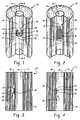
- FIG. 1is a cut-away perspective view of a paper roll showing a radio-frequency integrated circuit (“RFIC”) and an antenna positioned on the core of the paper roll according to one aspect of the invention where the antenna and RFIC are electrically coupled;
- RFICradio-frequency integrated circuit
- FIG. 2is a cut-away perspective view of a paper roll showing an alternative embodiment of an RFIC and an antenna positioned on the core where the antenna and RFIC are magnetically coupled;
- FIG. 3is a cross-sectional view of the paper roll of FIG. 1 taken at line 3 — 3 , showing the antenna positioned on an exterior surface of the core;
- FIG. 4is a cross-sectional view of a paper roll similar to that of FIG. 3 , but showing the antenna positioned on an inner surface of the core;
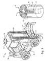
- FIG. 5is a schematic of a fork lift truck having clamp arms for engaging a roll of paper according to another aspect of the invention
- FIG. 6is a front plan view of a fork lift truck and clamp arms incorporating antennae and RFID readers attached to the fork lift truck;
- FIG. 7is a front plan view of a fork lift truck and clamp arms incorporating different antennae and RFID readers attached to the fork lift truck;
- FIG. 8is a front plan view of a fork lift truck and clamp arms incorporating an antenna and an RFID reader positioned around the lift mast of the fork lift truck;
- FIG. 9is a front plan view of a fork lift truck and clamp arms incorporating an antenna embedded in each of the clamp arms, with the RFID readers positioned on the clamp arms;
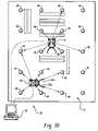
- FIG. 10is a schematic top view of a warehouse having a plurality of RFID transmitters for communicating to several fork lift trucks at the same time in the warehouse;
- FIG. 11is a schematic of a fork lift truck in a warehouse in communication with the RFID transmitters.
- FIG. 12is a schematic top view of an alternative embodiment of a warehouse having a plurality of RFID inlets installed in a grid pattern in the floor of the warehouse.
- FIGS. 1–4show a paper roll 10 having an RFID inlet 26 installed on the core 14 of the paper roll 10 .
- FIGS. 5–12show a material handling device in the form of a fork lift truck 18 having an RFID reader 20 and a reader antenna 60 installed on the fork lift truck 18 .
- Another aspect of the inventionrelates to a method of tracking inventory 16 in a warehouse 12 using the system.
- Inventory 16 in a warehouse 12is typically stacked in multiple rows and columns, several rows deep and high. Inventory may include boxes or cases of products, among other types of inventory known to those of skill in the art.
- One type of inventory for which the invention is particularly usefulis rolls of paper. Rolls of paper in a warehouse environment may be stored up to approximately 13 rolls deep and 3 rolls high. A typical roll of paper ranges in diameter from about 2 to 8 feet, is approximately 6 to 8 feet tall, and weighs approximately 1 ton.
- a roll of paper 10includes a core 14 of a sturdy material, such as compressed paper fibers.
- the material that makes up the core layermay be 1 ⁇ 2 to 1 inch thick or more and is shaped in the form of a tube.
- a continuous sheet of stock 24is wound around the core 14 .
- the stock 24may be any type of material.
- An RFID inlet 26is positioned on the core 14 .
- the RFID inlet 26typically comprises a tag 32 in the form of a thin substrate having an antenna 36 positioned on the substrate, and a radio frequency integrated circuit (“RFIC”) 34 .
- the RFIC 34 and antenna 36are electrically coupled to one another, either by direct contact or by capacitive coupling.
- the RFIC 34may include semiconductor circuits having logic, memory, and RF circuitry, and may be a silicon-based chip, a polymer-based chip, or other chips that are known today or will be developed in the future.
- An antenna 36is positioned on the inlet 26 in electrical communication with the RFIC.
- the antenna 36is positioned on the tag 32 of the inlet 26 .
- the tag 32may be a paper or polymeric material, such as polyester, among other known materials.
- a pressure sensitive adhesive 38or other attachment medium, may be positioned on one side of the tag 32 for use in attaching the inlet 26 to the surface of the core 14 .
- the inlet 26may be applied using glues, hot melts, water activated adhesives, or other adhering mediums.
- the inlet 26may be applied to the core 14 with an automatic application device, such as a label applicator, which applies the inlet 26 to the outer surface of the core 14 after it has been formed into a tube.
- the inlet 26may be applied after the paper stock 24 has been wound around the core 14 .
- the inlet 26may be applied by hand or with an automated process.
- a preferred position for the inlet 26 on the core 14is near the center of the core, although the inlet 26 may be positioned at any location along the length of the core 14 .
- the antenna 36 on the tag substrate 32may be an inductive or a capacitive antenna 36 depending on the RF frequency chosen for the application.
- the RFID transponder 26may be an inductive or a capacitive system.
- One type of capacitive antennais shown in FIGS. 1 , 3 , and 4 .
- the capacitive antennaincludes two pads 40 of conductive material with a non-conductive gap positioned between the pads 40 .
- An RFIC 34is positioned in the gap in electrical contact with both pads 40 of the antenna.
- the RFIC 34has terminals (not shown) which may directly contact the pads 40 or may be otherwise connected to the pads 40 with separate connectors.
- the RFIC 34may alternatively be capacitively coupled to the antenna pads 40 .
- An inductive antenna in the form of a loop 42 with two endsis shown positioned on a tag 32 in FIG. 2 .
- the RFIC 34is in electrical contact with the ends of the loop 42 .
- One end of the loopis electrically coupled to one of the terminals of the RFIC 34 while the other end of the loop utilizes a bridging connector to couple to the other terminal of the RFIC 34 .
- the inlet 26may be positioned on an inner surface 44 of the core 14 , as shown in FIG. 4 , or on an outer surface 46 of the core 14 , as shown in FIGS. 1–3 .
- the inlet 26may also be embedded within the material of the core (not shown). When the inlet 26 is positioned on the outer surface 46 of the core 14 , it is positioned on the core 14 prior to the application of the stock 24 to the core 14 . Alternatively, when the inlet 26 is positioned on the internal surface 44 of the core 14 , it may be positioned on the core 14 either before or after the paper stock 24 is wound around the core 14 . In FIGS.
- the adhesive layer on the tagis shown attached to one side of the tag while the antenna and RFIC are positioned on the other side of the tag.
- the adhesive, antenna, and RFICmay all be positioned on the same side of the tag.
- the tag 32is the outer most surface of the inlet 26 once the adhesive 38 is applied to the surface of the core 14 , providing a degree of protection for the antenna and RFIC.
- RFIC 34 and antenna 36 combinationsother than those discussed above or shown in the figures may be utilized with the invention.
- the RFIC 34may be positioned on a tag 32 for ease in attachment to a surface of the core 14 , or may be directly applied to a surface of the core 14 or embedded in the core without a tag 32 .
- the antenna 36is generally positioned on the inlet 26
- the antenna 36may be positioned on the surface of the core 14 instead of on the inlet 26 .
- the RFIC 34which is electrically coupled to the antenna 36 , is positioned on a tag 32 or may be independent of a tag 32 .
- the antenna 36is positioned on the surface of the core 14 utilizing any known technique, such as printing a conductive ink, sputter coating a conductive material, etching, and hot foil stamping, among other known antenna depositing techniques.
- RFIC 34may be coupled to the antenna 36 by leads, connectors, interposers, or other known techniques for coupling an RFIC 34 to an antenna 36 .
- the system of the inventionmay be utilized with any type of inventory that is transportable by a fork lift truck 18 or similar material handling device.
- the inventorymay include a plurality of cardboard boxes that are filled with a product.
- An inlet 26may be positioned on an inner or outer surface of each of the cardboard boxes, positioned on the products themselves, or simply positioned inside the box on a floating inlet.
- Material handling devicessuch as fork lift trucks 18
- Fork lift trucks 18are typically used in a warehouse 12 to move inventory 16 , which is often stored on pallets.
- Fork lift trucks 18include attachments in the form of arms 22 for engaging and moving the pallets, as shown in FIG. 11 .
- the arms 22may also engage the inventory itself without the need for pallets, depending on the size and shape of the inventory.
- Clamp truckssuch as those shown in FIGS. 5–10 , are used to lift heavy rolls of paper.
- Clamp trucksinclude large curved arms 22 a having clamp pads 22 b .
- the clamp armswrap around the paper roll 10 , lift and transport the paper roll 10 , and deposit the roll in either a storage location within the warehouse 12 , or on a truck or train for transportation out of the warehouse 12 . Since rolls of paper can be costly, it is desirable to electronically track the location of rolls in a warehouse 12 .
- the present inventiontracks the location of rolls of paper by positioning an RFID inlet 26 (i.e., RFID transponder) on the core 14 of each paper roll 10 and installing a reader 20 on the fork lift truck 18 for communication with the RFIC positioned on the RFID inlet 26 .
- a warehouse position locating system 28tracks the location of each fork lift truck 18 in the warehouse 12 .
- a first computer processor 58is positioned on the fork lift truck 18 and a second computer processor 30 is positioned in the warehouse 12 . Based on the location of the truck in the warehouse, the position of the paper roll 10 is calculated and the position and the paper roll's associated unique ID(s) is communicated from the RFID reader 20 to the second computer processor 30 .
- the second computer processor 30includes a data processor and the data processor maintains the position information and corresponding unique ID for each item of inventory 16 .
- the second computer 30may link this information to another site, such as the internet, for offsite monitoring.
- the systempermits automatic, at a distance, non-line of sight communication.
- the system of the present designutilizes a fork lift truck 18 as a mobile carrier for an RFID reader 20 .
- the reader 20is in communication with the second computer processor 30 in the warehouse 12 and the first computer processor 58 that is positioned onboard the fork lift truck 18 .
- the reader 20is electrically or magnetically coupled to the RFID inlet.
- the systemalso utilizes a position locating system 28 , which is in communication with the second computer processor 30 and the first computer processor 58 .
- the second computer processor 30includes a database system for storing of data.
- the position locating system 28operates on principles similar to that of the global positioning system (“GPS”) and tracks the location of items of inventory 16 in the warehouse 12 .
- GPSglobal positioning system
- position locating system 28is a positional beam system, which utilizes RFID transmitters 48 and RFID receivers 50 positioned on each fork lift truck 18 , as shown in FIGS. 5 , 10 , and 11 .
- the RF polling systemis a receiver 50 having a spinning or stationary flat planar antenna(e) 54 positioned on top of each fork lift truck 18 and the transmitters are RFID beacons 48 positioned on the ceiling 52 of the warehouse 12 .
- the position locating system 28may also utilize a truck mounted inertial measurement unit 56 (“IMU”), in combination with distance sensors, or another location measurement device or sensor, which is used to track the location of the truck based upon the truck's movement.
- the position locating systemis comprised of several sub-systems.
- One subsystemis the Radio Frequency Direction Finding system (“RFDFS”), depicted in FIGS. 10 and 11 .
- the RFDFSincludes a plurality of RFID transmitters or beacons and at least one receiver,
- the systemprocesses a number of signals received by the receivers 50 from the beacons 48 and measures angular position difference information for a selected number of signals.
- the beacon signalsare received by each receiver 50 , and two of the signals are selected, digitized, and processed by the first onboard computer processor 58 .
- Triangulation and filtering algorithmsare stored in the onboard first computer processor 58 , as well as tracking algorithms that are utilized to process RFDFS/Location Measurement Device measurements.
- the algorithmsare applied to the signal data in the onboard computer processor 58 to calculate a position of the lift truck 18 in the warehouse 12 and a position of the item of inventory 16 .
- the programming in the first computer processormay also be utilized to calculate a position of a defined reference point in the warehouse.
- the reader 20communicates with the RFIC 34 in a conventional manner.
- the reader 20powers the RFIC 34 so that the RFIC 34 communicates information stored in the RFIC 34 to the reader 20 .
- the reader 20then communicates the information stored in the RFIC 34 to the second computer processor 30 .
- Material identification, manufacture date, customer, and other dataare preferably stored in the RFIC.
- the RFIC 34may be written to by the reader 20 to store additional information in the RFIC 34 , such as material weight. For example, if the paper roll 10 is moved from a first position in the warehouse to a conveyance, information regarding the shipping information may be written to the RFIC. The information may either be written over existing information, or added to existing information stored in the RFIC 34 .
- Informationis also updated in the second computer 30 whenever inventory 16 is moved in the warehouse, or removed from the warehouse.
- Each reader 20is preferably associated with a reader antenna 60 .
- readers 20are positioned on the arms 22 a of the fork lift truck 18 and a reader antenna 60 is associated with each of the readers 20 .
- the reader antenna 60is formed by coating each fork lift arm 22 a with a conductive material, such as a conductive ink, and coupling the fork lift arms 22 a to the reader 20 by an electrical connector (not shown).
- a reader 20is coupled to each arm so that the left arm represents an electrical potential that is separate from that of the right arm.
- the chargeis dissipated through the RFID transponder via the capacitive couple to allow communication between the readers 20 and the RFIC 34 that comes into proximity with the reader 20 .
- a reader antenna 60is positioned in a conductive loop 62 that extends outwardly from the fork lift truck 18 and the reader 20 is positioned on the fork lift truck 18 .
- the reader antenna 60is electrically coupled to the reader 20 by cables or other connectors.
- the reader antennamay include a rigid, conductive tube positioned in the shape of a loop 62 with several conductor turns.
- the loopmay include stabilizing members 70 that bisect the loop so that the loop forms a ladder-like configuration, as shown in FIG. 6 .
- the reader antennae 60may be positioned adjacent each other to form a grid that extends from or is positioned on the fork lift truck 18 .
- the reader antenna 60forms a loop shape without the need for stabilizing members, as shown in FIGS. 7–9 .
- the tubes of the antennaare preferably formed of a conductive material such as copper or aluminum.
- a wire transformeris suspended inside the tube and is buffered from the tube walls by a buffering material, such as an insulating dielectric.
- the wire transformeris in electrical communication with the reader 20 and is preferably connected to the reader by a cable or other connector.
- the conductive tube of the loop antenna 62is utilized to protect the antenna's wire transformer and is also used to shield the transformer from electromagnetic noise.
- the conductive tubeshelp to shield any electromagnetic noise and drain electromagnetic current to neutral. Other types of antenna configurations and shielding may also be utilized.
- the antennais preferably positioned so it does not interfere with the operation of the arms 22 , 22 a or pads 22 b.
- FIGS. 6–9show a variety of locations for the readers 20 and the reader antennae 60 .
- FIG. 6shows two ladder-like antenna loops, with one of the loops positioned on one side of the lift mast 64 and the other positioned on the other side of the lift mast 64 .
- the loopsare attached to the fork lift truck 18 by the back plate 66 with a bracket 68 .
- the back plate 66is the portion of the fork lift truck 18 where the attachments, such as the clamp arms 22 a , are connected.
- the loops 62are angled relative to the lift mast 64 in order to approach or obtain 360° RF coverage when an item of inventory is positioned in the arms 22 a .
- the loopsare fixed to the back plate 66 by the brackets 68 and do not move when the clamp arms 22 a move.
- the reader antenna loops 62move up and down with the movement of the arms 22 a .
- the antenna loopsare configured to not interfere with the movement of the clamp arms or the movement of the truck into tight spaces. In this regard, it is desirable that the loops do not extend outside the width of the truck 18 .
- Each reader antenna loop 62is positioned on the back plate 66 and coupled to the reader 20 by a cable.
- the reader 20may range in size depending on the manufacturer, with a typical size being approximately 6′′ ⁇ 4′′ ⁇ 2′′.
- a separate reader 20is generally provided for each reader antenna loop 62 , although a single reader may be used with multiplexed antennae.
- the readeris powered by the fork lift truck's electrical system, although a separate power system may alternatively be provided, if so desired.
- FIG. 7shows two reader loop antennae 62 , positioned on either side of the lift mast 64 .
- the loopsare attached to the lift mast 64 by brackets 68 , are not movable, and preferably extend the full height of the lift mast 64 .
- Readers 20are coupled to the loops 62 and are positioned on the lift mast 64 .
- the readers 20are electrically coupled to the antenna loops 62 by cables or other connectors.
- the antenna loops of FIG. 7are similar to the antenna loops of FIG. 6 , but do not include the stabilizing members 70 .
- the tubes that form the outer shell of the reader antenna loops 62are preferably of a size that permits them to be stable and sturdy without the need for stabilizing members 70 .
- 1′′ or 2′′ copper tubingmay be utilized to form the tube loops.
- the loopsare fixed in position by the brackets 68 and are preferably angled within the roll constant surface plane of the clamp arms 22 a and pads 22 b to provide 360° RF read coverage.
- the loops 62are preferably spaced from the lift mast 64 by a distance in order to prevent RF field loss between the lift mast 64 and the antenna loops 62 . A preferred spacing 2′′ to 4′′.
- FIG. 8shows a reader single loop antenna 62 that is positioned around and outlines the lift mast 64 .
- the loop 62includes tubes and a transformer similar to that discussed above, but is wider than prior embodiments due to the size of the lift mast 64 .
- the reader antenna 60is preferably spaced from the lift mast 64 by 2′′ to 4′′ in order to avoid any RF field loss between the mast 64 and the antenna 60 and is connected to the mast 64 by brackets 68 or other connectors.
- the antenna loop 62may wrap around the back of the mast 64 , as shown in FIG. 8 , or may extend over the top and under the bottom of the mast 64 .
- the reader 20is positioned on top of the lift mast 64 , although it could be positioned at other locations, such as on the antenna loop 62 or the truck body, among other locations.
- FIG. 9shows an alternative embodiment where the reader antenna loops 62 are recessed into the face 72 of the clamp arms 22 a and clamp pads 22 b .
- Two antenna loops 62are shown, one positioned on each clamp arm 22 a .
- the loops 62are tubes that are positioned in troughs on the clamp arms 22 a and clamp pads 22 b , and the readers 20 are positioned on their respective clamp arms 22 a .
- the loopsare recessed below the face 72 of the clamp arms 22 a /clamp pads 22 b in order to avoid any physical interference between the antenna loops and the inventory being transported.
- the antenna loops 62are suspended in an insulating dielectric positioned between the antenna loop and the metal trough. The insulating dielectric prevents the antenna loop from making contact with the metal of the clamp arm 22 a /clamp pad 22 b in order to avoid any electromagnetic interference or shorting out of the antenna.
- the reader antenna loop 62encompasses the back plate 66 .
- This embodimentis similar to that of FIG. 7 , except FIG. 7 shows the loop around the lift mast 64 .
- a clearance of 2′′ to 4′′ around the back plate 66is preferred in order to avoid any RF field loss.
- the reader 20may be positioned on the back plate 66 , the arms 22 a , 22 b the lift mast 64 , or the truck body.
- the reader antenna loops 62range in size depending on the size of the fork lift truck 18 and the arms 22 , 22 a , 22 b . In one embodiment, such as those where the loops are positioned on either side of the lift mast 64 , the width of the loop ranges from about 12′′ to about 24′′, with a preferred width being 20′′. In embodiments where the reader antenna 60 is positioned around the lift mast 64 or back plate 66 , the antenna may be wider, such as about 36′′.
- the height of the antenna loop 62is dependent on the range of coverage desired. For instance, if the lift mast 64 has a lift height of 48′′, the antenna also preferably has a read height of 48′′ or more. The antenna 60 will typically provide a read coverage for the entire height of the antenna. Therefore, if a read height of 50′′ is desired, the antenna should be at least 50′′ high.
- the height and width of the antenna 60determines the coverage area for reading the RFID inlets 26 positioned on inventory 16 .
- numerous items of inventory 16are positioned in or on the arms of the fork lift truck 18 at one time, such as where a pallet carries boxes of products, the reader 20 will read the RFIC 34 of each item of inventory 16 .
- the computerwill know that the particular item of inventory is on the pallet, but will not be able to determine the precise location of the inventory on the pallet.
- An alternative antenna/reader configurationmay be utilized similar to that shown in FIG. 6 , but incorporating a separate antenna loop and reader for each part of the ladder. With the configuration shown in FIG.
- the reader 20can be used to determine the location of the RFIC 34 with greater precision than where a larger, single loop is utilized.
- the first computer processor 58 on the truck 18utilizes algorithms to more precisely determine the position of the RFIC 34 by cycling the readers 20 and using field of strength measurements, among other methods.
- the reader 20 on the fork lift arms 22 , 22 acan be Motorola's BiStatix, Philips' Icode, or any other reader that meets the electrical requirements of the system. Since the paper on the roll creates losses in the radio frequency signal from the reader 20 and RFIC 34 , a lower frequency signal may be required to avoid excessive attenuation losses.
- the conductive surface of the reader 20does not have high frequency reflections at the paper interface, which helps to reduce reflected energy losses.
- the fork lift reader 20may be activated automatically or manually.
- the reader 20may be manually activated by the fork lift operator by activating a switch when desired to obtain a reading from the RFIC 34 or to write to the RFIC 34 .
- the switchmay be positioned in the cab of the fork lift truck 18 and may be engaged by the operator when the clamp arms 22 a are in close proximity to an item of inventory 16 .
- the inventory 16may be in the grasp of the clamp arms 22 a or pads 22 b , or may be positioned near the clamp arms 22 a or clamp pads 22 b . In order for the reader 20 to properly interrogate the RFIC 34 , it must be close enough to the inventory 16 to obtain a reading.
- the necessary proximity requirementis driven by the size and type of antenna 36 that is coupled to the RFIC 34 installed on the core 14 , the size and type of antenna 60 coupled to the reader 20 on the fork lift arms 22 , 22 a , the distance and type of material through which the reader 20 and RFIC 34 signal must travel, the location of the reader 20 relative to the RFIC 34 , and the existence of any obstructions between the reader 20 and the RFIC 34 , among other factors.
- the reader 20may alternatively be automatically activated.
- the reader 20may be activated when the clamp arms 22 a or pads 22 b come in contact with the paper roll 10 .
- a pressure switchmay be positioned on the clamp arms or pads and activated when the clamp arms 22 a have contacted a roll of paper 10 .
- switches or sensorsare positioned on the clamp arms 22 a and activate when the clamp arms 22 a or pads 22 b are brought to a point towards one another that signals the clamp arms have engaged a roll of paper 10 .
- pressure switchesare associated with the movement of the clamp arms 22 a .
- the clamp arms 22 atypically include hydraulics that move the arms inwardly and outwardly to grasp a roll of paper 10 , transport it, and deposit it. In order to grasp a roll of paper 10 and transport it, the clamp arms 22 a apply pressure to the roll.
- Pressure switchesare coupled to the movement of the clamp arms 22 a in a conventional manner and are sensitive to the pressure being applied by the clamp arms 22 a or clamp pads 22 b as they grasp a roll of paper 10 .
- the first processordetects and directs the reader 20 to activate and communicate with the RFIC 34 .
- the pressure level of the clamp arms 22 apasses by the triggering level and, once again, the reader 20 communicates with the RFIC 34 and first computer processor 58 .
- the reader 20interrogates the RFIC 34 and reads the data stored in the RFIC 34 .
- the location of the paper roll 10is determined using the position locating system 28 .
- the position informationis transmitted from the first computer processor 58 to the second computer processor 30 for later use. Each time the paper roll 10 is moved, the position information is preferably updated in the second computer processor 30 .
- the position informationmay be stored even when the paper rolls 10 are loaded into trucks and railway cars for transportation to customers.
- the position locating system 28can survey the frontier of the warehouse to determine when a fork lift truck 18 has left the frontier, such as when a truck 18 leaves the warehouse to deposit a roll of paper in a train or truck for transport to the customer.
- automatic input into the second computer processor 30occurs when an item of inventory is removed from the warehouse.
- the position locating system 28is activated automatically to determine the position of the receivers 50 on the fork lift trucks 18 at appropriate operation periods, such as when the truck 18 is positioning an item of inventory 16 in the warehouse 12 .
- the RFID receivers 50are continuously receiving the RFID beacon signals to continually determine the position of the RFID receivers, although other embodiments may use a periodic, rather than a continuous sampling.
- the number of RFID beacons 48 needed for the warehouse position locating system 28will depend upon warehouse size, density of paper rolls, operating frequency, and the number of electromagnetic scattering objects.
- FIG. 10shows a warehouse 12 having multiple beacons 48 .
- FIG. 11shows a warehouse having four beacons 48 .
- the RFID beacon densitymay be uniform or non-uniform.
- the beacons 48are transmitters that transmit RF signals at a specific frequency, where each beacon transmits a different frequency, such as is known with Frequency Division Multiple Access (“FDMA”) Systems. Each frequency is tied to a specific beacon and the receivers can determine which beacon they are receiving signals from based upon the frequency of the signal they receive. Additionally, the second computer's database maps out the location of each beacon. Through triangulation techniques, the receiver location is determined by calculating the angular location of the sensed beacon in relation to the same beacon's absolute location. In a large warehouse, frequencies may be duplicated when transmitters are spaced so far apart that confusion of location is not likely.
- the beacons 48are fixed at specific locations so that when an RF signal is received by the receiver 50 , the location of the signal can be precisely determined. The spacing of the beacons 48 is determined using known spacing techniques.
- the receiver 50is preferably mounted on the fork lift truck 18 and includes a spinning and/or flat stationary planar antenna(e) for use in continually communicating with the RFID beacons 48 .
- the receiver 50communicates with all beacons 48 in its relative vicinity and, utilizing tracking algorithms stored in the first computer processor 58 , selects several of the signals for processing.
- the tracking algorithmspreferably select the beacons 48 proactively, by seeking out new beacons 48 as the receiver 50 is moved about the warehouse 12 .
- the proactive nature of the tracking algorithmadds to the stability of the system, since the receiver is continually receiving angular measurements from several beacons 48 at a time.
- the receiver 50has numerous modules (hardware), some of which include programming for receiving high frequency signals and down converting them to lower frequencies. Other modules include programming for digitizing the signals for use with the algorithms in the first computer processor 58 .
- the modulesare stored within the first computer processor housing 58 and spinner assembly housing 54 .
- a warehouse environmentis potentially susceptible to multipath errors due to metal or other structures in the warehouse 12 that reflect the electromagnetic waves emitted by the RFID beacons 48 .
- Multipath errorsare caused when a radio signal is received directly by an antenna, but then the same signal is received again as it is reflected off an interfering structure.
- the use of “Preprocessing” filtersminimizes the instability effects that multipath may cause by selectively ignoring beacon multipath measurements. Preprocessing filters can be used on radio signals to filter out any erroneous signals. The signals may then be further refined in a Kalman Filter, which is a known multiple-input software filter that can optimally select or reject, in real time, the sensor inputs based on the quality of the respective sensor measurements.
- the Kalman filtermay reject erroneous sensor inputs to calculate the desired output of the position locating system 28 with the location measurement unit 56 , and a Kalman filter provides improved overall navigation accuracy.
- the Kalman filtermay reside in the receiver 50 , in the first computer processor 58 , or in the second computer processor 30 .
- a preferred location for the Kalman Filteris in the first computer processor 58 .
- a location measurement device 56such as an inertial measurement unit (“IMU”), is positioned on the fork lift truck 18 and used to track the location of the truck 18 in RF “blind” areas.
- Inertial measurement units 56are self-contained position measurement devices that monitor position based upon the movement of the vehicle.
- Distance sensorsare preferably coupled to the inertial measurement unit to monitor movement of the truck 18 .
- IMU'smay include such features as a lateral accelerometer, a longitudinal accelerometer, a yaw rate gyro, and other devices for determining distance traveled and accurate stop state, among other components.
- the inertial measurement unit 56can also be utilized to measure the fork lift trucks heading angle through the use of an electronic compass compared to that of a reference (i.e., true North) for use in calculating the position of the truck.
- the unit 56makes calculations of the position of the receiver 50 based upon the movement of the vehicle and maintains a stable calculation up to about 12 seconds. It works in concert with the RFDFS 28 , which updates the “absolute” position of the receiver 50 based upon measurements taken from the beacons 48 through the receiver 50 .
- the inertial measurement unit 56 and distance sensorsupdate the Kalman filter during time periods between Kalman filter updates by the RFDFS 28 . In this way, the Kalman filter output is stable during movements and the system continually has position information.
- location measurement unit 57may also be used as the location measurement unit 57 instead of the IMU.
- position informationcan be determined by using distance sensors, which are typically coupled to the wheels of the truck and are used to determine distance traveled based upon rotation of the wheels, in combination with an electric compass, which is used to establish heading. A combination of these two devices are used to determine the position of the truck between updates from the position locating system. Other devices, besides those described above, may also be utilized to determine the position of the truck between updates.
- location measurement deviceis used herein to describe either a typical inertial measurement unit or other types of devices. The purpose of the location measurement device is to determine the location of the truck between communications with the position locating system.
- the position of the receiver 50 in the warehouse 12is determined through triangulation calculations of known RFID beacon locations in the warehouse 12 .
- Algorithms utilized to perform the position calculationsare stored in the first onboard processor 58 .
- the second computer processor 30is generally utilized for storing inventory data and for handling communications to the lift truck 18 drivers. In order to avoid overloading the second computer processor 30 with the numerous calculations necessary to determine the position of the receiver 50 , these calculations are preferably performed on the first onboard computer processor 58 .
- the necessary algorithms for determining the position of the lift truck 18 in the warehouse 12are preferably stored in the first computer processor 58 .
- These algorithmstake the signals received from all the beacons 48 in relative proximity to the truck 18 and perform a triangulation calculation to determine the position.
- two of the beacons 48are utilized to perform the triangulation calculation. Therefore, two signals are selected from the numerous signals received by the first onboard processor 58 .
- the triangulation techniquemeasures the angular position of the spinner when the known beacon position is read.
- the first onboard computer processor 58is utilized to resolve errors from the calculations to improve the accuracy of the calculated position information. Algorithms are utilized to resolve errors that are inherent in the system such as multipath, partial blockage, or other errors, as known by those of skill in the art. As previously discussed, one algorithm that may be used to correct for any erroneous measurements in the position calculation is a Kalman Filter.
- the first computer processor 58also includes algorithms for use in calculating the position of the item of inventory 16 based upon the calculated position of the lift truck 18 .
- the algorithms stored in the first computer processoruse an x-y offset to determine where the center of the core 14 is based on the size of the paper roll and the orientation of the truck 18 .
- An algorithmmay also be utilized to determine the height at which the paper roll is positioned to account for stacking of the paper rolls 10 .
- the fork lift truck 18preferably includes a device for determining the deposit height of the roll.
- the core center locationis the position information transmitted to the RFIC 34 and second computer processor 30 .
- the receiver 50 on the fork lift truck 18first runs an initial sweep of all the beacons 48 in the immediate vicinity of the truck 18 to determine an initial position of the truck 18 .
- Paper roll position informationis also transmitted to the second computer processor 30 whenever inventory is moved.
- the position locating system 28stores the position of each roll, with an accuracy of approximately ⁇ 1 foot.
- the second computer processor 30can provide an immediate warning when inventory is improperly positioned in the warehouse 12 , and can proactively suggest the proper material placement position.
- the second computer processor 30can provide independent verification of shipment contents, interface with all warehouse tracking system software packages, provide inventory reports if so desired, and may be linked to the internet.
- the systemmay be expanded to also include readers positioned at other places within the manufacturing and transportation system, such as on paper machine rewinders and process points, as well as on trucks or train cars, the invention not being limited to placement of readers 20 on fork lift trucks 18 alone.
- the receivers 50may be positioned as stationary receivers at points within the warehouse 12 to provide a type of Differential GPS system, as known by those of skill in the art.
- the fork lift truck 18includes the beacon transmitter 48 and receivers 50 are positioned throughout the warehouse 12 .
- the captured positional datawill be processed by the first computer processor 58 and the unique information on the RFIC 34 on each item of inventory 16 will be sent to the second computer processor 30 for processing and distribution.
- the position locating system 28has been discussed herein in the context of a pseudo-GPS type system. Those of skill in the art will recognize that variations and improvements may be incorporated in the present disclosure to improve the operation of the system, according to currently existing knowledge in the art.
- the brief description of the position locating system discussed hereinillustrates several of many possible embodiments. Furthermore, the invention is not limited to the particular position locating system described herein. Other types of position locating systems may also be utilized, including those that are not based upon GPS principles.
- the RFDFS system(including the beacons and receivers) may be entirely replaced by a position locating system that includes RFIC's and their associated antennae installed in or on the floor 74 of the warehouse 12 .
- the RFIC'sare preferably passive and are powered by an external reader.
- a plurality of RFID inlets 26are installed in the floor 74 of the warehouse 12 in a regular grid pattern. The position of each RFIC on each inlet 26 within the grid is known since the inlets 26 are fixed positionally on the floor 74 .
- the inlets 26may be positioned on top of the floor 74 , or, in a preferred embodiment, are embedded in the floor 74 and covered by a protective material, such as a laminate.
- the RFID inlets 26replace the beacons 48 discussed above in connection with FIGS. 10 and 11 .
- a reader or readers positioned on the truck 18replace the receivers 50 .
- a single additional reader 76is installed on the truck 18 and is positioned for communicating with the RFIC's installed in the floor 74 .
- the readerhas an antenna 60 and the inlet 26 have antennae 36 .
- the reader antenna 60 and inlet antennae 36are configured to provide a limited read distance such that dead bands 78 are found on the floor 74 . In the dead bands, the reader 76 loses communication with the inlets 26 .
- the dead bands 78are utilized to avoid readings from two inlets 26 at a single time.
- the dead bands 78are configured such that only one RFID inlet 26 is readable at a single time by the reader 76 .
- the IMU 56or location measurement unit, may be utilized to supplement position information, as discussed above.
- Position informationcan be calculated by the onboard computer 58 and transmitted to the base station computer processor 30 via wireless means.
- two or more additional readers 76 , 80are positioned on the forklift truck 18 at spaced locations from each other.
- one reader 76is positioned at the front of the truck 18 and the other 80 is positioned at the rear of the truck 18 .
- the multiple readerscan be used together to triangulate a position of the truck 18 .
- the other reader 80which is preferably not positioned in a dead band 78 , can continue to determine the position of the truck 18 until the other reader 76 reestablishes contact with an inlet 26 .
- the readerscan actually replace the IMU 56 and its associated sensors so that the position of the truck 18 can be determined in a less mechanically complicated manner.
- a single readercould be utilized that has multiple antennae positioned around the truck body. The reader can multiplex through the multiple antennae to obtain readings from nearby inlets 26 . The multiple readings can be used to triangulate a position of the truck 18 . Two or more antennae can be positioned around the truck. Since readings can be performed in a continuous manner, the IMU can be eliminated.
- Readings performed by the readers 76 , 80are preferably continuous, but may be intermittent.
- the inlets 26may alternatively be powered to provide a longer read range, if desired.
- Dead bands 78may be sized so that they are smaller in width and length than a typical fork lift truck 18 in order to minimize the likelihood that two or more of the antennae will be positioned in a dead band 78 at a single time.
- the systems described aboveprovide a number of benefits in real time, including the ability to track the location of inventory, improve warehouse utilization by mapping the warehouse, improve the placement of inventory utilizing an alarm system, provide independent shipment verification, and provide an electronic physical inventory.
- a reader and reader antenna similar to that depicted in FIG. 6were tested and achieved full read/write capability through a base stock roll of paper that was 75 inches thick.
- full mast height read coveragewas attained with the antenna design so that the reader 20 could read all stacked rows of paper.
- the RFIC 34is passive. However, a semi-passive or active system is also contemplated for use with the present design. If a semi-passive or active RFIC is utilized, a battery is coupled to the RFIC.
- a sensormay be electrically coupled to the RFIC for communication with the RFIC, such as a MEMS (micro electromechanical system) sensor. The sensor may be used to read environmental or other conditions, including physical and chemical properties, in the vicinity of the sensor. Examples of environmental properties include temperature, pressure, and humidity, among other conditions. Multiple sensors may be utilized with a single or multiple RFICs.
- the sensorscan transmit a sensed condition to the RFIC when commanded to do so.
- the RFICmay be passive, semi-passive, or active.
- the readerpowers the RFIC and the RFIC then takes a reading of the condition with the sensor. The sensed condition is then transmitted back to the reader.
- the RFICis active or semi-passive, it is battery powered such that the RFIC and a clock on the RFIC are continually powered.
- the battery powered RFICcan independently signal the sensor periodically to sense a condition and the sensed condition is transmitted to the RFIC for storage in a log or immediate transmission to a reader.
- Certain types of sensorsalso require battery power and the power needed by the sensor may be provided by the same battery that is utilized to power the RFIC.
- the sensorcan be built directly into the RFIC or connected to the RFIC by a connector. Alternatively, the sensor can operate by wireless signal transfer, so that a physical link between the sensor and RFIC is not required.
- the sensor and batterymay be positioned on the substrate of the tag, or may be positioned independently of the substrate and electrically coupled to the RFIC.
- One type of passive sensor that may be utilized, for example, to read a temperatureis manufactured by SCS of San Diego, Calif.
- a type of active sensor that may be utilized, for example, to record temperature datais manufactured by KSW of Germany. Other types of sensors may also be utilized.
- tags, inlets, and radio frequency integrated circuitsare contemplated for use with the claimed invention.
- tag suppliersinclude Poly Flex Circuits, Cross Technologies, and Global ID.
- RFIC suppliersinclude Philips Semiconductor, Temic, and E. M.
- the preferred tagsare low profile in order to avoid marking the paper on the roll.
Landscapes
- Engineering & Computer Science (AREA)
- Physics & Mathematics (AREA)
- General Physics & Mathematics (AREA)
- Theoretical Computer Science (AREA)
- Health & Medical Sciences (AREA)
- Toxicology (AREA)
- Electromagnetism (AREA)
- Artificial Intelligence (AREA)
- Computer Vision & Pattern Recognition (AREA)
- General Health & Medical Sciences (AREA)
- Computer Networks & Wireless Communication (AREA)
- Computer Hardware Design (AREA)
- Microelectronics & Electronic Packaging (AREA)
- Transportation (AREA)
- Structural Engineering (AREA)
- Civil Engineering (AREA)
- Life Sciences & Earth Sciences (AREA)
- Geology (AREA)
- Mechanical Engineering (AREA)
- Forklifts And Lifting Vehicles (AREA)
- Warehouses Or Storage Devices (AREA)
Abstract
Description
Claims (1)
Priority Applications (10)
| Application Number | Priority Date | Filing Date | Title |
|---|---|---|---|
| US10/305,525US7151979B2 (en) | 2002-11-26 | 2002-11-26 | System and method for tracking inventory |
| US10/369,315US20040102870A1 (en) | 2002-11-26 | 2003-02-19 | RFID enabled paper rolls and system and method for tracking inventory |
| CA2500363ACA2500363C (en) | 2002-11-26 | 2003-11-26 | Rfid enabled paper rolls and system for tracking inventory |
| AU2003301514AAU2003301514A1 (en) | 2002-11-26 | 2003-11-26 | Rfid enabled paper rolls and system for tracking inventory |
| PCT/US2003/037785WO2004075103A1 (en) | 2002-11-26 | 2003-11-26 | Rfid enabled paper rolls and system for tracking inventory |
| NZ540248ANZ540248A (en) | 2002-11-26 | 2003-11-26 | RFID enabled paper rolls and system for tracking inventory |
| US11/253,366US7818088B2 (en) | 2002-11-26 | 2005-10-19 | System and method for tracking inventory |
| US11/269,299US20060058913A1 (en) | 2002-11-26 | 2005-11-08 | Inventory tracking |
| US12/883,926US8295974B2 (en) | 2002-11-26 | 2010-09-16 | System and method for tracking inventory |
| US13/657,078US8774960B2 (en) | 2002-11-26 | 2012-10-22 | System and method for tracking inventory |
Applications Claiming Priority (1)
| Application Number | Priority Date | Filing Date | Title |
|---|---|---|---|
| US10/305,525US7151979B2 (en) | 2002-11-26 | 2002-11-26 | System and method for tracking inventory |
Related Child Applications (3)
| Application Number | Title | Priority Date | Filing Date |
|---|---|---|---|
| US10/369,315Continuation-In-PartUS20040102870A1 (en) | 2002-11-26 | 2003-02-19 | RFID enabled paper rolls and system and method for tracking inventory |
| US11/253,366DivisionUS7818088B2 (en) | 2002-11-26 | 2005-10-19 | System and method for tracking inventory |
| US11/269,299Continuation-In-PartUS20060058913A1 (en) | 2002-11-26 | 2005-11-08 | Inventory tracking |
Publications (2)
| Publication Number | Publication Date |
|---|---|
| US20040102869A1 US20040102869A1 (en) | 2004-05-27 |
| US7151979B2true US7151979B2 (en) | 2006-12-19 |
Family
ID=32325445
Family Applications (4)
| Application Number | Title | Priority Date | Filing Date |
|---|---|---|---|
| US10/305,525Expired - Fee RelatedUS7151979B2 (en) | 2002-11-26 | 2002-11-26 | System and method for tracking inventory |
| US11/253,366Expired - Fee RelatedUS7818088B2 (en) | 2002-11-26 | 2005-10-19 | System and method for tracking inventory |
| US12/883,926Expired - Fee RelatedUS8295974B2 (en) | 2002-11-26 | 2010-09-16 | System and method for tracking inventory |
| US13/657,078Expired - LifetimeUS8774960B2 (en) | 2002-11-26 | 2012-10-22 | System and method for tracking inventory |
Family Applications After (3)
| Application Number | Title | Priority Date | Filing Date |
|---|---|---|---|
| US11/253,366Expired - Fee RelatedUS7818088B2 (en) | 2002-11-26 | 2005-10-19 | System and method for tracking inventory |
| US12/883,926Expired - Fee RelatedUS8295974B2 (en) | 2002-11-26 | 2010-09-16 | System and method for tracking inventory |
| US13/657,078Expired - LifetimeUS8774960B2 (en) | 2002-11-26 | 2012-10-22 | System and method for tracking inventory |
Country Status (1)
| Country | Link |
|---|---|
| US (4) | US7151979B2 (en) |
Cited By (53)
| Publication number | Priority date | Publication date | Assignee | Title |
|---|---|---|---|---|
| US20050080554A1 (en)* | 2003-03-27 | 2005-04-14 | Takashi Ono | Area information provision system and method |
| US20060071790A1 (en)* | 2004-09-29 | 2006-04-06 | Duron Mark W | Reverse infrastructure location system and method |
| US20060208892A1 (en)* | 2005-03-01 | 2006-09-21 | Ehrman Kenneth S | Mobile portal for rfid applications |
| US20060255949A1 (en)* | 2005-05-13 | 2006-11-16 | Ems Technologies, Inc. | Pallet jack antenna for RFID system |
| US20070008152A1 (en)* | 2005-06-10 | 2007-01-11 | Thomas Parias | Embedded rfid scanner for mobile product management |
| US20070013510A1 (en)* | 2005-07-11 | 2007-01-18 | Honda Motor Co., Ltd. | Position management system and position management program |
| US20070096922A1 (en)* | 2005-11-03 | 2007-05-03 | Ems Technologies, Inc. | Removable mount for mounting an electronic system component on a forklift |
| US20070109125A1 (en)* | 2005-07-25 | 2007-05-17 | The Hong Kong University Of Science And Technology | Robust RFID-Based System and Method for Precise In-House Positioning |
| US20070131781A1 (en)* | 2005-12-08 | 2007-06-14 | Ncr Corporation | Radio frequency device |
| US20070188318A1 (en)* | 2006-02-15 | 2007-08-16 | International Business Machines Corporation | Dynamic boundary mapping using position-determination systems |
| US20070282482A1 (en)* | 2002-08-19 | 2007-12-06 | Q-Track Corporation | Asset localization identification and movement system and method |
| US20080068170A1 (en)* | 2005-03-01 | 2008-03-20 | I.D. Systems, Inc. | System and method for reading and verifying RFID tags |
| US7417544B2 (en)* | 2004-10-15 | 2008-08-26 | Samsung Electro-Mechanics Co., Ltd | Location tracking system and method |
| US20080297348A1 (en)* | 2007-05-30 | 2008-12-04 | Onderko John C | RFID System for Lifting Devices |
| US20090015494A1 (en)* | 2007-07-11 | 2009-01-15 | Jungheinrich Aktiengesellschaft | Industrial truck with at least one antenna for sending and receiving data |
| US20090027163A1 (en)* | 2007-07-26 | 2009-01-29 | Chia-Ching Su | Radio Frequency Identification Tag Holding and Paper Roll Assembly |
| US20090048026A1 (en)* | 2007-08-14 | 2009-02-19 | French John B | Smart card holder for automated gaming system and gaming cards |
| US20090058756A1 (en)* | 2007-08-31 | 2009-03-05 | Wen-Chia Kuo | Antenna supporter, antenna assembly and machine having the antenna assembly |
| US20090281655A1 (en)* | 2008-05-08 | 2009-11-12 | Cascade Corporation | Control system for a load handling clamp |
| US7656296B2 (en) | 2005-05-13 | 2010-02-02 | Ems Technologies, Inc. | Antenna for mobile wireless data collection system |
| US20100217630A1 (en)* | 1999-05-19 | 2010-08-26 | I.D. Systems, Inc. | Systems and methods for remote vehicle rental |
| US20100283709A1 (en)* | 2009-05-08 | 2010-11-11 | Sonoco Development, Inc. | Structure Having An Antenna Incorporated Therein |
| US20110054731A1 (en)* | 2009-08-31 | 2011-03-03 | Derose Lynn Ann | System and method for bi-directional wireless information transfer |
| US7948384B1 (en) | 2007-08-14 | 2011-05-24 | Mpt, Inc. | Placard having embedded RFID device for tracking objects |
| US20120282070A1 (en)* | 2006-06-09 | 2012-11-08 | D Andrea Raffaello | Method and System for Transporting Inventory Items |
| US8326451B2 (en) | 2002-08-19 | 2012-12-04 | Q-Track Corporation | Inventory control and method |
| US8346630B1 (en)* | 2006-06-30 | 2013-01-01 | Intuit Inc. | Method and apparatus to efficiently verify inventory |
| US8535136B2 (en) | 2007-08-14 | 2013-09-17 | John B. French | Read and write playing care |
| US8640514B2 (en) | 2011-06-22 | 2014-02-04 | The Stanley Works Israel Ltd. | Electronic and manual lock assembly |
| US8640513B2 (en) | 2011-06-22 | 2014-02-04 | The Stanley Works Israel Ltd. | Electronic and manual lock assembly |
| US8755929B2 (en) | 2012-10-29 | 2014-06-17 | Cascade Corporation | Interactive clamp force control system for load handling clamps |
| US8774960B2 (en) | 2002-11-26 | 2014-07-08 | Totaltrax, Inc. | System and method for tracking inventory |
| US8831878B2 (en) | 2010-09-13 | 2014-09-09 | Systec Conveyors, Inc. | Ground location of work truck |
| US20140369799A1 (en)* | 2013-06-17 | 2014-12-18 | Cascade Corporation | Tissue roll-handling clamp |
| US8928463B2 (en) | 2009-05-22 | 2015-01-06 | The Stanley Works Israel Ltd. | Object management system and method |
| US9014971B2 (en) | 2010-09-13 | 2015-04-21 | Systec Corporation | Ground location of work truck |
| US9114963B2 (en) | 2013-02-26 | 2015-08-25 | Cascade Corporation | Clamping surface positioning system for mobile load-handling clamps |
| US9354070B2 (en) | 2013-10-31 | 2016-05-31 | Crown Equipment Corporation | Systems, methods, and industrial vehicles for determining the visibility of features |
| US9436184B2 (en) | 2006-06-09 | 2016-09-06 | Amazon Technologies, Inc. | Method and system for transporting inventory items |
| US9472075B1 (en) | 2015-06-04 | 2016-10-18 | Tyco Fire & Security Gmbh | Systems and methods for locating items in a facility |
| US9477938B1 (en)* | 2014-12-03 | 2016-10-25 | Amazon Technologies, Inc. | Mobile RFID reading systems |
| US9658622B2 (en) | 2015-05-06 | 2017-05-23 | Crown Equipment Corporation | Industrial vehicle for identifying malfunctioning sequenced tag and tag layout for use therewith |
| US9818003B2 (en) | 2015-05-06 | 2017-11-14 | Crown Equipment Corporation | Diagnostic tag for an industrial vehicle tag reader |
| US20170372184A1 (en)* | 2016-06-24 | 2017-12-28 | Crown Equipment Corporation | Indirect electronic badge tracking |
| US10134253B2 (en) | 2015-06-04 | 2018-11-20 | Tyco Fire & Security Gmbh | Systems and methods for locating and determining the orientation of a handheld device |
| US10198685B2 (en) | 2016-06-24 | 2019-02-05 | Crown Equipment Corporation | Electronic badge to authenticate and track industrial vehicle operator |
| US10217041B2 (en)* | 2015-07-21 | 2019-02-26 | Systemes Et Technologies Identification (Stid) | Radio-frequency identification device for a tubular element to be identified in a constrained environment |
| US10257646B2 (en) | 2016-06-24 | 2019-04-09 | Crown Equipment Corporation | Use of electronic badges in aisle passing maneuvers |
| US10255769B2 (en) | 2016-06-24 | 2019-04-09 | Crown Equipment Corporation | Electronic badge as a talking marker |
| US10445685B2 (en)* | 2016-06-24 | 2019-10-15 | Amazon Technologies, Inc. | Delivery confirmation using overlapping geo-fences |
| US20190370738A1 (en)* | 2014-10-24 | 2019-12-05 | Fellow, Inc. | Methods and apparatus for wireless inventory determinations |
| US10586082B1 (en) | 2019-05-29 | 2020-03-10 | Fellow, Inc. | Advanced micro-location of RFID tags in spatial environments |
| US20200339353A1 (en)* | 2018-01-12 | 2020-10-29 | Fuji Corporation | Storage device and storage method |
Families Citing this family (80)
| Publication number | Priority date | Publication date | Assignee | Title |
|---|---|---|---|---|
| US8077040B2 (en) | 2000-01-24 | 2011-12-13 | Nextreme, Llc | RF-enabled pallet |
| US7342496B2 (en) | 2000-01-24 | 2008-03-11 | Nextreme Llc | RF-enabled pallet |
| US20060058913A1 (en)* | 2002-11-26 | 2006-03-16 | Andersen Scott P | Inventory tracking |
| JP4283084B2 (en)* | 2003-10-14 | 2009-06-24 | シャープ株式会社 | palette |
| US20050200457A1 (en)* | 2004-03-11 | 2005-09-15 | Raj Bridgelall | Inventory transport device with integrated RFID reader |
| US7102518B2 (en)* | 2004-04-05 | 2006-09-05 | Sonoco Development, Inc. | Removable identification device for multilayer tubular structures |
| US7038587B2 (en)* | 2004-04-05 | 2006-05-02 | Sonoco Development, Inc. | Identification device for multilayer tubular structures |
| US7121457B2 (en)* | 2004-04-30 | 2006-10-17 | Kimberly-Clark Worldwide, Inc. | Automatically adjusting parameters of a lifting device by identifying objects to be lifted |
| US7770792B2 (en)* | 2004-06-23 | 2010-08-10 | Sap Ag | Methods and systems for managing stock transportation |
| US7669763B2 (en)* | 2004-06-23 | 2010-03-02 | Sap Ag | Methods and system for managing stock |
| FI20040895A7 (en)* | 2004-06-29 | 2005-12-30 | Top Tunniste Oy | Method and arrangement for using an RFID tag in the identification of rolled goods |
| US7614555B2 (en)* | 2004-09-09 | 2009-11-10 | The Gillette Company | RFID sensor array |
| GB0423409D0 (en) | 2004-10-21 | 2004-11-24 | Core Control Ltd | A core for a roll of material |
| US8403618B2 (en)* | 2004-11-30 | 2013-03-26 | Cascade Corporation | Lift truck load handler |
| CN100395767C (en)* | 2004-12-17 | 2008-06-18 | 香港理工大学 | Reference positioning system using radio frequency identification technology and stacking management system for container yard |
| US7323989B2 (en) | 2005-02-22 | 2008-01-29 | International Business Machines Corporation | Product locating method and system |
| US20060208893A1 (en)* | 2005-02-28 | 2006-09-21 | Anson Gary S | Weight audit methods and systems utilizing data reader |
| US20060255943A1 (en)* | 2005-05-16 | 2006-11-16 | Psc Scanning, Inc. | Induction charging machine, methods, and system for a data reader |
| ATE431584T1 (en)* | 2005-05-27 | 2009-05-15 | Charles Machine Works | DETERMINING THE POSITION OF A REMOTE CONTROL USER |
| DE102005024882A1 (en)* | 2005-05-31 | 2006-12-07 | Still Gmbh | Truck |
| DE102005024883A1 (en)* | 2005-05-31 | 2006-12-07 | Still Gmbh | Industrial truck for communication system, has transmission device transmitting vehicle-based data, data for recognition and removal of malfunction and interferences and operational data, and formed as transmitting and receiving unit |
| DE102005024881A1 (en)* | 2005-05-31 | 2006-12-07 | Still Gmbh | Industrial truck with an electrical control unit |
| US7236851B2 (en)* | 2005-06-17 | 2007-06-26 | Epc4Roi Limited Partnership | Self-contained RF identification apparatus for pallet conveyances |
| US7155304B1 (en)* | 2005-06-17 | 2006-12-26 | Epc4Roi Limited Partnership | RF identification apparatus for pallet conveyances |
| GB0518020D0 (en)* | 2005-09-05 | 2005-10-12 | Warren Point Comm Ltd | System and method for tracking movable items in an industrial facility |
| US20070108296A1 (en)* | 2005-11-14 | 2007-05-17 | Konopka John A | Radio frequency identification devices and methods |
| US8369981B2 (en)* | 2005-12-14 | 2013-02-05 | Ncr Corporation | Methods and apparatus for managing location information for movable objects |
| US7391338B2 (en)* | 2005-12-21 | 2008-06-24 | International Business Machines Corporation | Apparatus and method using a sensor to detect improper orientation of an object |
| US20070213869A1 (en)* | 2006-02-08 | 2007-09-13 | Intermec Ip Corp. | Cargo transporter with automatic data collection devices |
| DE102006014447A1 (en)* | 2006-03-29 | 2007-10-04 | Jungheinrich Aktiengesellschaft | Industrial truck, has fork occupancy sensor provided to detect load on loading fork, and control unit that initiates activation of transmitting and receiving unit for receiving data from external transponder, when sensor has detected load |
| US20070239312A1 (en)* | 2006-04-10 | 2007-10-11 | Andersen Scott P | System and method for tracking inventory movement using a material handling device |
| US20080030320A1 (en)* | 2006-08-03 | 2008-02-07 | Deere & Company, A Delaware Corporation | Agricultural lift with data gathering capability |
| CA2558626C (en)* | 2006-09-21 | 2008-05-20 | Tenxc Wireless Inc. | Highly-accurate radio location of beacons in a warehouse |
| US20080079542A1 (en)* | 2006-09-26 | 2008-04-03 | Broadcom Corporation, A California Corporation | Radio frequency identification (RFID) carrier and system |
| US7821400B2 (en)* | 2006-09-29 | 2010-10-26 | Datalogic Scanning, Inc. | System and method for verifying number of wireless tagged items in a transaction |
| US11225404B2 (en) | 2006-12-13 | 2022-01-18 | Crown Equipment Corporation | Information system for industrial vehicles |
| US10600256B2 (en) | 2006-12-13 | 2020-03-24 | Crown Equipment Corporation | Impact sensing usable with fleet management system |
| US10013815B2 (en)* | 2006-12-13 | 2018-07-03 | Crown Equipment Corporation | Information system for industrial vehicles |
| EP3699012B1 (en)* | 2006-12-13 | 2024-05-08 | Crown Equipment Corporation | Fleet management system |
| US9984341B2 (en) | 2006-12-13 | 2018-05-29 | Crown Equipment Corporation | Information system for industrial vehicles including cyclical recurring vehicle information message |
| FR2915599B1 (en)* | 2007-04-27 | 2009-07-24 | Hub Telecom Sa | SYSTEM FOR LOCATING A CONTAINER IN A STORAGE AREA AND ASSOCIATED LOCATION METHOD |
| CN101828307A (en) | 2007-09-11 | 2010-09-08 | Rf控制有限责任公司 | Radiofrequency signal is obtained and source location system |
| US7723647B2 (en)* | 2007-09-28 | 2010-05-25 | Illinois Tool Works Inc. | Information communication systems between components of a hot melt adhesive material dispensing system |
| KR100796531B1 (en)* | 2007-11-05 | 2008-01-21 | 신화엘컴주식회사 | Location Management System and Location Management Method for Moving Objects |
| WO2009109923A1 (en)* | 2008-03-05 | 2009-09-11 | Ipico South Africa (Proprietary) Limited | A method of attaching a rfid tag to a cylindrical article, to a rfid tag-containing article, and to a rfid tag |
| GB0805589D0 (en)* | 2008-03-27 | 2008-04-30 | British Telecomm | Records components reader |
| SG196831A1 (en)* | 2009-01-17 | 2014-02-13 | Boomerang Systems Inc | Automated storage system and transport vehicle |
| US8120488B2 (en)* | 2009-02-27 | 2012-02-21 | Rf Controls, Llc | Radio frequency environment object monitoring system and methods of use |
| US8344823B2 (en) | 2009-08-10 | 2013-01-01 | Rf Controls, Llc | Antenna switching arrangement |
| AU2010282536B2 (en) | 2009-08-12 | 2015-04-09 | Crown Equipment Corporation | Information system for industrial vehicles |
| EP2473966B1 (en) | 2009-09-01 | 2019-11-06 | Crown Equipment Corporation | Information system for industrial vehicles including cyclical recurring vehicle information message |
| CN102483809B (en)* | 2009-09-10 | 2015-01-21 | Rf控制有限责任公司 | Calibration and operational assurance method and apparatus for rfid object monitoring systems |
| KR101821837B1 (en)* | 2010-04-08 | 2018-01-24 | 액세스 비지니스 그룹 인터내셔날 엘엘씨 | Point of sale inductive systems and methods |
| DE202010012161U1 (en)* | 2010-09-02 | 2011-01-05 | Sae Schaarschmidt Analytic Engineering Gmbh | Industrial truck |
| US20120262292A1 (en)* | 2011-04-14 | 2012-10-18 | Martin Moser | Portable device inventory tracking |
| EP2753565B1 (en) | 2011-09-07 | 2015-07-08 | J. Schmalz GmbH | Method for monitoring an operating state of a device and corresponding device and system |
| NL2008946C2 (en)* | 2012-06-06 | 2013-12-09 | Berend Breman | CYLINDER-MADE PRODUCT, RECORDING DEVICE, VEHICLE AND METHOD. |
| CN103712654A (en)* | 2014-01-07 | 2014-04-09 | 北京联合大学 | Intelligent monitoring system for warehouse environment |
| MA36838A1 (en)* | 2014-03-18 | 2016-01-29 | Oritech Sarl | Automatic device for monitoring the inventory of rolled materials |
| DE102014116964A1 (en)* | 2014-11-20 | 2016-05-25 | Océ Printing Systems GmbH & Co. KG | Method and device for localizing a print job in a printing center |
| CN104808538A (en)* | 2014-11-25 | 2015-07-29 | 山东永泰化工有限公司 | Intelligent management system of tyre warehosue |
| JP6398702B2 (en)* | 2014-12-25 | 2018-10-03 | 大日本印刷株式会社 | Paper residual quantity measurement system and paper residual quantity measurement device |
| CN109478246B (en)* | 2016-07-15 | 2021-12-10 | 株式会社村田制作所 | RFID tag manufacturing device and RFID tag manufacturing method |
| US20190128994A1 (en)* | 2017-10-31 | 2019-05-02 | Richard Kozdras | Sensor system |
| CN107934864B (en)* | 2017-11-14 | 2019-12-20 | 浙江科技学院 | Self-supervision method and control system of explosion-proof forklift |
| DE102017223552A1 (en)* | 2017-12-21 | 2019-06-27 | Robert Bosch Gmbh | Cable drum for receiving a cable |
| WO2019167206A1 (en)* | 2018-02-28 | 2019-09-06 | 三菱重工機械システム株式会社 | Stock-paper-roll management system and stock-paper-roll management method |
| CN110390365B (en) | 2018-04-16 | 2022-11-22 | 台达电子工业股份有限公司 | Vehicle Tracking System and Method |
| EP3576248B1 (en)* | 2018-05-31 | 2023-05-31 | STMicroelectronics Austria GmbH | Nfc reader |
| DE102018131267A1 (en)* | 2018-12-07 | 2020-06-10 | Sick Ag | Goods transport system and method for removing dropped goods |
| DE102019201599A1 (en)* | 2019-02-07 | 2020-08-13 | Bhs Intralogistics Gmbh | Transfer order |
| CN110092232B (en)* | 2019-05-05 | 2020-10-13 | 惠安县品创工业设计有限公司 | Electronic tags prevents that roll up presses quality control machine of bending |
| WO2021122381A1 (en)* | 2019-12-19 | 2021-06-24 | Nv Bekaert Sa | Smart spool having sensor and communication device |
| IT202000006934A1 (en)* | 2020-04-02 | 2021-10-02 | Crono Log S R L | SUPPORT AND ROTATION GROUP FOR A REEL, MACHINE INCLUDING THIS GROUP, METHOD FOR DRAWING A MATERIAL WRAPPED ON A REEL IN SAID GROUP. |
| US20220391796A1 (en)* | 2020-08-12 | 2022-12-08 | Everseen Limited | System and Method for Mapping Risks in a Warehouse Environment |
| CN116802136A (en)* | 2020-12-30 | 2023-09-22 | 塞玛2有限公司 | Automatic coil reading device with RFID tag, related system and tracking method |
| CN113409294B (en)* | 2021-06-30 | 2023-03-24 | 广东利元亨智能装备股份有限公司 | Core-pulling detection method of roll core, electronic equipment and storage medium |
| CN113353855A (en)* | 2021-07-02 | 2021-09-07 | 合肥方源机电有限公司 | Fork truck's fork truck bucket presss from both sides |
| JP2023127437A (en)* | 2022-03-01 | 2023-09-13 | 大王製紙株式会社 | Roll body management device |
| WO2024047415A1 (en)* | 2022-08-31 | 2024-03-07 | Agco Corporation | Hay bale rfid reader antenna configuration |
Citations (95)
| Publication number | Priority date | Publication date | Assignee | Title |
|---|---|---|---|---|
| US3169242A (en) | 1963-03-19 | 1965-02-09 | Gen Electric | Identification interrogating system |
| US3568161A (en) | 1968-09-04 | 1971-03-02 | Elwyn Raymond Knickel | Vehicle locator system |
| US3707711A (en) | 1970-04-02 | 1972-12-26 | Peter Harold Cole | Electronic surveillance system |
| US3720940A (en) | 1970-09-29 | 1973-03-13 | H Fox | Method and apparatus for sorting packages and the like |
| US3780368A (en) | 1970-02-20 | 1973-12-18 | Svejsecentralen | Method of marking and subsequently localizing, identifying and recording physical objects |
| US3952304A (en) | 1973-11-23 | 1976-04-20 | Hughes Aircraft Company | Tracking system utilizing Kalman filter concepts |
| US4063229A (en) | 1967-03-30 | 1977-12-13 | Sensormatic Electronics Corporation | Article surveillance |
| US4068232A (en) | 1976-02-12 | 1978-01-10 | Fairchild Industries, Inc. | Passive encoding microwave transponder |
| US4533167A (en)* | 1984-02-13 | 1985-08-06 | Honeywell Inc. | Robotics manipulator with gripping force control means |
| US4656463A (en) | 1983-04-21 | 1987-04-07 | Intelli-Tech Corporation | LIMIS systems, devices and methods |
| US4673932A (en) | 1983-12-29 | 1987-06-16 | Revlon, Inc. | Rapid inventory data acquistion system |
| US4725186A (en)* | 1986-05-13 | 1988-02-16 | Laminated Papers, Inc. | Lift truck with vacuum load-supporting assembly |
| US4827395A (en) | 1983-04-21 | 1989-05-02 | Intelli-Tech Corporation | Manufacturing monitoring and control systems |
| US4888593A (en) | 1987-12-15 | 1989-12-19 | Signal Science, Inc. | Time difference of arrival geolocation method, etc. |
| US5113349A (en)* | 1988-03-26 | 1992-05-12 | Fuji Electric Co. Ltd. | Method and system for storing/removing and distributing articles of manufacture |
| US5134277A (en) | 1983-11-07 | 1992-07-28 | Australian Meat And Live-Stock Corporation | Remote data transfer system with ambient light insensitive circuitry |
| US5235326A (en) | 1991-08-15 | 1993-08-10 | Avid Corporation | Multi-mode identification system |
| US5252962A (en) | 1990-08-03 | 1993-10-12 | Bio Medic Data Systems | System monitoring programmable implantable transponder |
| US5254997A (en) | 1992-07-31 | 1993-10-19 | Westinghouse Electric Corp. | Retrodirective interrogation responsive system |
| US5260694A (en)* | 1992-01-10 | 1993-11-09 | Ndc Automation, Inc. | Automatic article tracking system for manually operated delivery system |
| US5260711A (en) | 1993-02-19 | 1993-11-09 | Mmtc, Inc. | Difference-in-time-of-arrival direction finders and signal sorters |
| US5261800A (en) | 1991-07-30 | 1993-11-16 | Daikin Industries, Ltd. | Compressor, and method of manufacturing same including a press-fit inlet tube |
| US5289372A (en) | 1992-08-18 | 1994-02-22 | Loral Aerospace Corp. | Global equipment tracking system |
| US5292219A (en)* | 1990-02-23 | 1994-03-08 | Auramo Cargo Systems Oy | Procedure and apparatus for the handling of loads |
| US5387916A (en) | 1992-07-31 | 1995-02-07 | Westinghouse Electric Corporation | Automotive navigation system and method |
| US5406263A (en) | 1992-07-27 | 1995-04-11 | Micron Communications, Inc. | Anti-theft method for detecting the unauthorized opening of containers and baggage |
| US5434775A (en) | 1993-11-04 | 1995-07-18 | The General Hospital Corporation | Managing an inventory of devices |
| US5451939A (en) | 1990-08-20 | 1995-09-19 | Fisher-Rosemount Limited | Microprocessor controlled transmitter for connection to a sensor and a method of transferring digital signals to the microprocessor |
| US5461385A (en) | 1994-04-29 | 1995-10-24 | Hughes Identification Devices, Inc. | RF/ID transponder system employing multiple transponders and a sensor switch |
| US5481245A (en) | 1994-01-11 | 1996-01-02 | Grumman Aerospace Corporation | Monitored environment container |
| US5528232A (en) | 1990-06-15 | 1996-06-18 | Savi Technology, Inc. | Method and apparatus for locating items |
| US5548106A (en) | 1994-08-30 | 1996-08-20 | Angstrom Technologies, Inc. | Methods and apparatus for authenticating data storage articles |
| US5594448A (en) | 1993-10-22 | 1997-01-14 | Texas Instruments Incorporated | Highly accurate RF-ID positioning system |
| US5627517A (en) | 1995-11-01 | 1997-05-06 | Xerox Corporation | Decentralized tracking and routing system wherein packages are associated with active tags |
| GB2308947A (en) | 1996-01-04 | 1997-07-09 | I D Systems Ltd | Identification tag with environmental sensing facility |
| US5686902A (en) | 1990-06-15 | 1997-11-11 | Texas Instruments Incorporated | Communication system for communicating with tags |
| EP0824245A1 (en) | 1996-08-09 | 1998-02-18 | Ferag AG | Mobile object carrying electronic data which can read and/or write contactlessly |
| US5760742A (en) | 1995-05-12 | 1998-06-02 | Trimble Navigation Limited | Integrated mobile GIS/GPS/AVL with wireless messaging capability |
| US5774876A (en) | 1996-06-26 | 1998-06-30 | Par Government Systems Corporation | Managing assets with active electronic tags |
| US5791801A (en) | 1996-08-30 | 1998-08-11 | Siebe North, Inc. | Liquid applicator |
| US5791861A (en)* | 1995-07-31 | 1998-08-11 | Seelig; David L. | Rotatable vacuum lifting and transporting apparatus |
| US5798693A (en) | 1995-06-07 | 1998-08-25 | Engellenner; Thomas J. | Electronic locating systems |
| US5798694A (en) | 1996-12-19 | 1998-08-25 | Motorola, Inc. | Food storage apparatus and methods and systems for monitoring a food item |
| US5821859A (en) | 1996-06-07 | 1998-10-13 | Ibm Corporation | Concealed magnetic ID code and antitheft tag |
| US5831531A (en) | 1992-07-27 | 1998-11-03 | Micron Communications, Inc. | Anti-theft method for detecting the unauthorized opening of containers and baggage |
| US5850187A (en) | 1996-03-27 | 1998-12-15 | Amtech Corporation | Integrated electronic tag reader and wireless communication link |
| WO1999005658A1 (en) | 1997-07-25 | 1999-02-04 | Checkpoint Systems, Inc. | Electrically, physically or virtually reactivating rfid tags |
| US5887176A (en) | 1996-06-28 | 1999-03-23 | Randtec, Inc. | Method and system for remote monitoring and tracking of inventory |
| US5908135A (en) | 1995-11-21 | 1999-06-01 | Bradford Company | Sleeve pack |
| GB2333207A (en) | 1998-01-09 | 1999-07-14 | Peter George Milton | A transponder mounted on a core of a reel of paper to track the paper from the mill to a printing press |
| US5936523A (en) | 1998-04-24 | 1999-08-10 | West; Joe F. | Device and method for detecting unwanted disposition of the contents of an enclosure |
| US5963134A (en) | 1997-07-24 | 1999-10-05 | Checkpoint Systems, Inc. | Inventory system using articles with RFID tags |
| US5971587A (en) | 1997-08-01 | 1999-10-26 | Kato; Kiroku | Package and mail delivery system |
| US5973599A (en) | 1997-10-15 | 1999-10-26 | Escort Memory Systems | High temperature RFID tag |
| US5997064A (en)* | 1996-12-06 | 1999-12-07 | Tsubakimoto Chain Co. | Article gripping apparatus |
| US6027302A (en) | 1996-04-26 | 2000-02-22 | Nymek Ab | Clamp force control for load-handling device |
| US6027027A (en) | 1996-05-31 | 2000-02-22 | Lucent Technologies Inc. | Luggage tag assembly |
| US6031503A (en) | 1997-02-20 | 2000-02-29 | Raytheon Company | Polarization diverse antenna for portable communication devices |
| US6091332A (en) | 1998-06-09 | 2000-07-18 | Motorola, Inc. | Radio frequency identification tag having printed circuit interconnections |
| WO2000058752A1 (en) | 1999-03-30 | 2000-10-05 | Microchip Technology Incorporated | Radio frequency identification tag device with sensor input |
| US6130613A (en) | 1998-06-09 | 2000-10-10 | Motorola, Inc. | Radio frequency indentification stamp and radio frequency indentification mailing label |
| US6148291A (en) | 1998-01-26 | 2000-11-14 | K & T Of Lorain, Ltd. | Container and inventory monitoring methods and systems |
| US6150921A (en) | 1996-10-17 | 2000-11-21 | Pinpoint Corporation | Article tracking system |
| US6201499B1 (en) | 1998-02-03 | 2001-03-13 | Consair Communications | Time difference of arrival measurement system |
| US6208910B1 (en)* | 1999-04-23 | 2001-03-27 | Pitney Bowes Inc. | System and method for determining the location of a mail piece |
| US6206292B1 (en) | 1999-01-23 | 2001-03-27 | Sihl Gmbh | Surface-printable RFID-transponders |
| US6232877B1 (en) | 1998-03-02 | 2001-05-15 | Konisa Limited | Security system |
| US6237051B1 (en) | 1997-07-24 | 2001-05-22 | Data Capture Institute | Asset tracking within and across enterprise boundaries |
| US6246327B1 (en) | 1998-06-09 | 2001-06-12 | Motorola, Inc. | Radio frequency identification tag circuit chip having printed interconnection pads |
| US20010004236A1 (en) | 1999-05-17 | 2001-06-21 | Letkomiller Joseph Michael | Response adjustable temperature sensor for transponder |
| US6255962B1 (en) | 1998-05-15 | 2001-07-03 | System Excelerator, Inc. | Method and apparatus for low power, micro-electronic mechanical sensing and processing |
| US6259369B1 (en) | 1999-09-30 | 2001-07-10 | Moore North America, Inc. | Low cost long distance RFID reading |
| US6272457B1 (en) | 1996-09-16 | 2001-08-07 | Datria Systems, Inc. | Spatial asset management system that time-tags and combines captured speech data and captured location data using a predifed reference grammar with a semantic relationship structure |
| US6285282B1 (en) | 2000-09-05 | 2001-09-04 | Motorola, Inc. | System and apparatus for detecting and communicating a freshness of a perishable product |
| US20010035815A1 (en) | 1999-12-29 | 2001-11-01 | Richard Fletcher | Platform for item sensing and identification |
| US6332098B2 (en)* | 1998-08-07 | 2001-12-18 | Fedex Corporation | Methods for shipping freight |
| US20020008621A1 (en) | 2000-01-06 | 2002-01-24 | Isogon Corporation | Method and system for determining the inventory and location of assets |
| US20020016829A1 (en) | 1998-03-19 | 2002-02-07 | Isochron Data Corporation | Remote data acquisition, transmission and analysis system including handheld wireless equipment |
| US6353406B1 (en) | 1996-10-17 | 2002-03-05 | R.F. Technologies, Inc. | Dual mode tracking system |
| US20020035524A1 (en) | 2000-09-21 | 2002-03-21 | Martin Husslage | System and method for monitoring inventory amounts and locations |
| US20020038267A1 (en) | 2000-09-05 | 2002-03-28 | Necmettin Can | System and method for using radio frequency identification in retail operations |
| US6373389B1 (en) | 2000-04-21 | 2002-04-16 | Usm Systems, Ltd. | Event driven information system |
| US20020044096A1 (en) | 2000-10-16 | 2002-04-18 | Chung Kevin Kwong-Tai | Antenna array for smart RFID tags |
| US20020057208A1 (en) | 1998-09-25 | 2002-05-16 | Fong-Jei Lin | Inventory control system using r.f. object identification |
| US6396438B1 (en) | 1999-09-24 | 2002-05-28 | Slc Technologies | System and method for locating radio frequency identification tags using three-phase antenna |
| US20020067267A1 (en) | 2000-03-15 | 2002-06-06 | Richard Kirkham | Package identification system |
| US20020070862A1 (en) | 2000-12-12 | 2002-06-13 | Francis Robert C. | Object tracking and management system and method using radio-frequency identification tags |
| US20020089434A1 (en) | 2000-11-06 | 2002-07-11 | Ohanes Ghazarian | Electronic vehicle product and personnel monitoring |
| US6496806B1 (en) | 1999-12-16 | 2002-12-17 | Samsys Technologies Inc. | Method and system for tracking clustered items |
| US6542114B1 (en)* | 2000-09-07 | 2003-04-01 | Savi Technology, Inc. | Method and apparatus for tracking items using dual frequency tags |
| US6669089B2 (en)* | 2001-11-12 | 2003-12-30 | 3M Innovative Properties Co | Radio frequency identification systems for asset tracking |
| US6747560B2 (en) | 2002-06-27 | 2004-06-08 | Ncr Corporation | System and method of detecting movement of an item |
| US6819243B2 (en)* | 2000-04-03 | 2004-11-16 | Mikko Keskilammi | Method and apparatus for identifying bulk goods, preferably roll-like bulk goods |
| US6817522B2 (en) | 2003-01-24 | 2004-11-16 | Hewlett-Packard Development Company, L.P. | System and method for distributed storage management |
| US6901304B2 (en) | 2002-01-11 | 2005-05-31 | Sap Aktiengesellschaft | Item tracking system architectures providing real-time visibility to supply chain |
Family Cites Families (11)
| Publication number | Priority date | Publication date | Assignee | Title |
|---|---|---|---|---|
| DE4002801C1 (en) | 1990-01-31 | 1991-04-11 | Texas Instruments Deutschland Gmbh, 8050 Freising, De | |
| CA2176790A1 (en) | 1995-05-25 | 1996-11-26 | Peter R. Lowe | Transponder system for the remote communication of a physical condition |
| US5706742A (en)* | 1996-01-29 | 1998-01-13 | Hamrick; Joseph T. | Method of feeding solid particles from a zone of low pressure to a zone of high pressure |
| US6549891B1 (en)* | 1996-03-26 | 2003-04-15 | Recovery Management Corporation | Method for managing inventory |
| US5986547A (en)* | 1997-03-03 | 1999-11-16 | Korver; Kelvin | Apparatus and method for improving the safety of railroad systems |
| US6021499A (en)* | 1998-03-31 | 2000-02-01 | Sony Corporation Of Japan | Isolated ground reference DC power supply |
| US6660418B1 (en)* | 1998-06-15 | 2003-12-09 | Aer Energy Resources, Inc. | Electrical device with removable enclosure for electrochemical cell |
| US6714121B1 (en)* | 1999-08-09 | 2004-03-30 | Micron Technology, Inc. | RFID material tracking method and apparatus |
| WO2002031789A1 (en)* | 2000-10-10 | 2002-04-18 | Escort Memory Systems | Modular rfid antenna system |
| US6721657B2 (en)* | 2001-06-04 | 2004-04-13 | Novatel, Inc. | Inertial GPS navigation system |
| US7151979B2 (en) | 2002-11-26 | 2006-12-19 | International Paper Company | System and method for tracking inventory |
- 2002
- 2002-11-26USUS10/305,525patent/US7151979B2/ennot_activeExpired - Fee Related
- 2005
- 2005-10-19USUS11/253,366patent/US7818088B2/ennot_activeExpired - Fee Related
- 2010
- 2010-09-16USUS12/883,926patent/US8295974B2/ennot_activeExpired - Fee Related
- 2012
- 2012-10-22USUS13/657,078patent/US8774960B2/ennot_activeExpired - Lifetime
Patent Citations (108)
| Publication number | Priority date | Publication date | Assignee | Title |
|---|---|---|---|---|
| US3169242A (en) | 1963-03-19 | 1965-02-09 | Gen Electric | Identification interrogating system |
| US4063229A (en) | 1967-03-30 | 1977-12-13 | Sensormatic Electronics Corporation | Article surveillance |
| US3568161A (en) | 1968-09-04 | 1971-03-02 | Elwyn Raymond Knickel | Vehicle locator system |
| US3780368A (en) | 1970-02-20 | 1973-12-18 | Svejsecentralen | Method of marking and subsequently localizing, identifying and recording physical objects |
| US3707711A (en) | 1970-04-02 | 1972-12-26 | Peter Harold Cole | Electronic surveillance system |
| US3720940A (en) | 1970-09-29 | 1973-03-13 | H Fox | Method and apparatus for sorting packages and the like |
| US3952304A (en) | 1973-11-23 | 1976-04-20 | Hughes Aircraft Company | Tracking system utilizing Kalman filter concepts |
| US4068232A (en) | 1976-02-12 | 1978-01-10 | Fairchild Industries, Inc. | Passive encoding microwave transponder |
| US4827395A (en) | 1983-04-21 | 1989-05-02 | Intelli-Tech Corporation | Manufacturing monitoring and control systems |
| US4656463A (en) | 1983-04-21 | 1987-04-07 | Intelli-Tech Corporation | LIMIS systems, devices and methods |
| US5134277A (en) | 1983-11-07 | 1992-07-28 | Australian Meat And Live-Stock Corporation | Remote data transfer system with ambient light insensitive circuitry |
| US4673932A (en) | 1983-12-29 | 1987-06-16 | Revlon, Inc. | Rapid inventory data acquistion system |
| US4533167A (en)* | 1984-02-13 | 1985-08-06 | Honeywell Inc. | Robotics manipulator with gripping force control means |
| US4725186A (en)* | 1986-05-13 | 1988-02-16 | Laminated Papers, Inc. | Lift truck with vacuum load-supporting assembly |
| US4888593A (en) | 1987-12-15 | 1989-12-19 | Signal Science, Inc. | Time difference of arrival geolocation method, etc. |
| US5113349A (en)* | 1988-03-26 | 1992-05-12 | Fuji Electric Co. Ltd. | Method and system for storing/removing and distributing articles of manufacture |
| US5292219A (en)* | 1990-02-23 | 1994-03-08 | Auramo Cargo Systems Oy | Procedure and apparatus for the handling of loads |
| US5528232A (en) | 1990-06-15 | 1996-06-18 | Savi Technology, Inc. | Method and apparatus for locating items |
| US5686902A (en) | 1990-06-15 | 1997-11-11 | Texas Instruments Incorporated | Communication system for communicating with tags |
| US5252962A (en) | 1990-08-03 | 1993-10-12 | Bio Medic Data Systems | System monitoring programmable implantable transponder |
| US6054935A (en) | 1990-08-03 | 2000-04-25 | Bio Medic Data Systems, Inc. | System monitoring programmable implantable transponder |
| US5422636A (en) | 1990-08-03 | 1995-06-06 | Bio Medic Data Systems, Inc. | System monitoring programmable implantable transponder |
| US5451939A (en) | 1990-08-20 | 1995-09-19 | Fisher-Rosemount Limited | Microprocessor controlled transmitter for connection to a sensor and a method of transferring digital signals to the microprocessor |
| US5261800A (en) | 1991-07-30 | 1993-11-16 | Daikin Industries, Ltd. | Compressor, and method of manufacturing same including a press-fit inlet tube |
| US5235326A (en) | 1991-08-15 | 1993-08-10 | Avid Corporation | Multi-mode identification system |
| US5260694A (en)* | 1992-01-10 | 1993-11-09 | Ndc Automation, Inc. | Automatic article tracking system for manually operated delivery system |
| US5406263A (en) | 1992-07-27 | 1995-04-11 | Micron Communications, Inc. | Anti-theft method for detecting the unauthorized opening of containers and baggage |
| US5831531A (en) | 1992-07-27 | 1998-11-03 | Micron Communications, Inc. | Anti-theft method for detecting the unauthorized opening of containers and baggage |
| US5646592A (en) | 1992-07-27 | 1997-07-08 | Micron Communications, Inc. | Anti-theft method for detecting the unauthorized opening of containers and baggage |
| US5387916A (en) | 1992-07-31 | 1995-02-07 | Westinghouse Electric Corporation | Automotive navigation system and method |
| US5254997A (en) | 1992-07-31 | 1993-10-19 | Westinghouse Electric Corp. | Retrodirective interrogation responsive system |
| US5289372A (en) | 1992-08-18 | 1994-02-22 | Loral Aerospace Corp. | Global equipment tracking system |
| US5260711A (en) | 1993-02-19 | 1993-11-09 | Mmtc, Inc. | Difference-in-time-of-arrival direction finders and signal sorters |
| US5594448A (en) | 1993-10-22 | 1997-01-14 | Texas Instruments Incorporated | Highly accurate RF-ID positioning system |
| US5434775A (en) | 1993-11-04 | 1995-07-18 | The General Hospital Corporation | Managing an inventory of devices |
| US5481245A (en) | 1994-01-11 | 1996-01-02 | Grumman Aerospace Corporation | Monitored environment container |
| US5461385A (en) | 1994-04-29 | 1995-10-24 | Hughes Identification Devices, Inc. | RF/ID transponder system employing multiple transponders and a sensor switch |
| US5548106A (en) | 1994-08-30 | 1996-08-20 | Angstrom Technologies, Inc. | Methods and apparatus for authenticating data storage articles |
| US5760742A (en) | 1995-05-12 | 1998-06-02 | Trimble Navigation Limited | Integrated mobile GIS/GPS/AVL with wireless messaging capability |
| US6057756A (en) | 1995-06-07 | 2000-05-02 | Engellenner; Thomas J. | Electronic locating systems |
| US6388569B1 (en) | 1995-06-07 | 2002-05-14 | Thomas J. Engellenner | Electronic locating methods |
| US5798693A (en) | 1995-06-07 | 1998-08-25 | Engellenner; Thomas J. | Electronic locating systems |
| US5791861A (en)* | 1995-07-31 | 1998-08-11 | Seelig; David L. | Rotatable vacuum lifting and transporting apparatus |
| US5627517A (en) | 1995-11-01 | 1997-05-06 | Xerox Corporation | Decentralized tracking and routing system wherein packages are associated with active tags |
| US5908135A (en) | 1995-11-21 | 1999-06-01 | Bradford Company | Sleeve pack |
| GB2308947A (en) | 1996-01-04 | 1997-07-09 | I D Systems Ltd | Identification tag with environmental sensing facility |
| US5850187A (en) | 1996-03-27 | 1998-12-15 | Amtech Corporation | Integrated electronic tag reader and wireless communication link |
| US6027302A (en) | 1996-04-26 | 2000-02-22 | Nymek Ab | Clamp force control for load-handling device |
| US6027027A (en) | 1996-05-31 | 2000-02-22 | Lucent Technologies Inc. | Luggage tag assembly |
| US5821859A (en) | 1996-06-07 | 1998-10-13 | Ibm Corporation | Concealed magnetic ID code and antitheft tag |
| US5774876A (en) | 1996-06-26 | 1998-06-30 | Par Government Systems Corporation | Managing assets with active electronic tags |
| US5887176A (en) | 1996-06-28 | 1999-03-23 | Randtec, Inc. | Method and system for remote monitoring and tracking of inventory |
| US6488212B1 (en) | 1996-08-09 | 2002-12-03 | Ferag Ag | System for identifying and locating relative positions of objects |
| EP0824245B1 (en) | 1996-08-09 | 2004-05-19 | Ferag AG | Mobile object carrying electronic data which can read and/or write contactlessly |
| EP0824245A1 (en) | 1996-08-09 | 1998-02-18 | Ferag AG | Mobile object carrying electronic data which can read and/or write contactlessly |
| US5992739A (en) | 1996-08-09 | 1999-11-30 | Ferag Ag | Movable object carrying electronically stored data to be read and or/overwritten by a non-contact reading/writing device |
| US5791801A (en) | 1996-08-30 | 1998-08-11 | Siebe North, Inc. | Liquid applicator |
| US20010039489A1 (en) | 1996-09-16 | 2001-11-08 | Ford Terry Edward | Spatial asset management system and method |
| US20010053970A1 (en) | 1996-09-16 | 2001-12-20 | Ford Terry Edward | Spatial asset management system and method |
| US6272457B1 (en) | 1996-09-16 | 2001-08-07 | Datria Systems, Inc. | Spatial asset management system that time-tags and combines captured speech data and captured location data using a predifed reference grammar with a semantic relationship structure |
| US6150921A (en) | 1996-10-17 | 2000-11-21 | Pinpoint Corporation | Article tracking system |
| US6353406B1 (en) | 1996-10-17 | 2002-03-05 | R.F. Technologies, Inc. | Dual mode tracking system |
| US5997064A (en)* | 1996-12-06 | 1999-12-07 | Tsubakimoto Chain Co. | Article gripping apparatus |
| US5798694A (en) | 1996-12-19 | 1998-08-25 | Motorola, Inc. | Food storage apparatus and methods and systems for monitoring a food item |
| US6031503A (en) | 1997-02-20 | 2000-02-29 | Raytheon Company | Polarization diverse antenna for portable communication devices |
| US6237051B1 (en) | 1997-07-24 | 2001-05-22 | Data Capture Institute | Asset tracking within and across enterprise boundaries |
| US5963134A (en) | 1997-07-24 | 1999-10-05 | Checkpoint Systems, Inc. | Inventory system using articles with RFID tags |
| US6025780A (en) | 1997-07-25 | 2000-02-15 | Checkpoint Systems, Inc. | RFID tags which are virtually activated and/or deactivated and apparatus and methods of using same in an electronic security system |
| WO1999005658A1 (en) | 1997-07-25 | 1999-02-04 | Checkpoint Systems, Inc. | Electrically, physically or virtually reactivating rfid tags |
| US5971587A (en) | 1997-08-01 | 1999-10-26 | Kato; Kiroku | Package and mail delivery system |
| US5973599A (en) | 1997-10-15 | 1999-10-26 | Escort Memory Systems | High temperature RFID tag |
| GB2333207A (en) | 1998-01-09 | 1999-07-14 | Peter George Milton | A transponder mounted on a core of a reel of paper to track the paper from the mill to a printing press |
| US6148291A (en) | 1998-01-26 | 2000-11-14 | K & T Of Lorain, Ltd. | Container and inventory monitoring methods and systems |
| US6201499B1 (en) | 1998-02-03 | 2001-03-13 | Consair Communications | Time difference of arrival measurement system |
| US6232877B1 (en) | 1998-03-02 | 2001-05-15 | Konisa Limited | Security system |
| US20020016829A1 (en) | 1998-03-19 | 2002-02-07 | Isochron Data Corporation | Remote data acquisition, transmission and analysis system including handheld wireless equipment |
| US5936523A (en) | 1998-04-24 | 1999-08-10 | West; Joe F. | Device and method for detecting unwanted disposition of the contents of an enclosure |
| US6255962B1 (en) | 1998-05-15 | 2001-07-03 | System Excelerator, Inc. | Method and apparatus for low power, micro-electronic mechanical sensing and processing |
| US6130613A (en) | 1998-06-09 | 2000-10-10 | Motorola, Inc. | Radio frequency indentification stamp and radio frequency indentification mailing label |
| US6246327B1 (en) | 1998-06-09 | 2001-06-12 | Motorola, Inc. | Radio frequency identification tag circuit chip having printed interconnection pads |
| US6091332A (en) | 1998-06-09 | 2000-07-18 | Motorola, Inc. | Radio frequency identification tag having printed circuit interconnections |
| US6332098B2 (en)* | 1998-08-07 | 2001-12-18 | Fedex Corporation | Methods for shipping freight |
| US20020057208A1 (en) | 1998-09-25 | 2002-05-16 | Fong-Jei Lin | Inventory control system using r.f. object identification |
| US6206292B1 (en) | 1999-01-23 | 2001-03-27 | Sihl Gmbh | Surface-printable RFID-transponders |
| WO2000058752A1 (en) | 1999-03-30 | 2000-10-05 | Microchip Technology Incorporated | Radio frequency identification tag device with sensor input |
| US6208910B1 (en)* | 1999-04-23 | 2001-03-27 | Pitney Bowes Inc. | System and method for determining the location of a mail piece |
| US20010004236A1 (en) | 1999-05-17 | 2001-06-21 | Letkomiller Joseph Michael | Response adjustable temperature sensor for transponder |
| US6396438B1 (en) | 1999-09-24 | 2002-05-28 | Slc Technologies | System and method for locating radio frequency identification tags using three-phase antenna |
| US6259369B1 (en) | 1999-09-30 | 2001-07-10 | Moore North America, Inc. | Low cost long distance RFID reading |
| US6496806B1 (en) | 1999-12-16 | 2002-12-17 | Samsys Technologies Inc. | Method and system for tracking clustered items |
| US20010035815A1 (en) | 1999-12-29 | 2001-11-01 | Richard Fletcher | Platform for item sensing and identification |
| US20020008621A1 (en) | 2000-01-06 | 2002-01-24 | Isogon Corporation | Method and system for determining the inventory and location of assets |
| US20020067267A1 (en) | 2000-03-15 | 2002-06-06 | Richard Kirkham | Package identification system |
| US6819243B2 (en)* | 2000-04-03 | 2004-11-16 | Mikko Keskilammi | Method and apparatus for identifying bulk goods, preferably roll-like bulk goods |
| US6373389B1 (en) | 2000-04-21 | 2002-04-16 | Usm Systems, Ltd. | Event driven information system |
| US6717517B2 (en) | 2000-04-21 | 2004-04-06 | Usm Systems, Ltd. | Event driven information system |
| US6285282B1 (en) | 2000-09-05 | 2001-09-04 | Motorola, Inc. | System and apparatus for detecting and communicating a freshness of a perishable product |
| US20020038267A1 (en) | 2000-09-05 | 2002-03-28 | Necmettin Can | System and method for using radio frequency identification in retail operations |
| US6542114B1 (en)* | 2000-09-07 | 2003-04-01 | Savi Technology, Inc. | Method and apparatus for tracking items using dual frequency tags |
| US20020035524A1 (en) | 2000-09-21 | 2002-03-21 | Martin Husslage | System and method for monitoring inventory amounts and locations |
| US20020044096A1 (en) | 2000-10-16 | 2002-04-18 | Chung Kevin Kwong-Tai | Antenna array for smart RFID tags |
| US20020089434A1 (en) | 2000-11-06 | 2002-07-11 | Ohanes Ghazarian | Electronic vehicle product and personnel monitoring |
| US20020070862A1 (en) | 2000-12-12 | 2002-06-13 | Francis Robert C. | Object tracking and management system and method using radio-frequency identification tags |
| US6600418B2 (en)* | 2000-12-12 | 2003-07-29 | 3M Innovative Properties Company | Object tracking and management system and method using radio-frequency identification tags |
| US6669089B2 (en)* | 2001-11-12 | 2003-12-30 | 3M Innovative Properties Co | Radio frequency identification systems for asset tracking |
| US6901304B2 (en) | 2002-01-11 | 2005-05-31 | Sap Aktiengesellschaft | Item tracking system architectures providing real-time visibility to supply chain |
| US6747560B2 (en) | 2002-06-27 | 2004-06-08 | Ncr Corporation | System and method of detecting movement of an item |
| US6817522B2 (en) | 2003-01-24 | 2004-11-16 | Hewlett-Packard Development Company, L.P. | System and method for distributed storage management |
Cited By (111)
| Publication number | Priority date | Publication date | Assignee | Title |
|---|---|---|---|---|
| US20100217630A1 (en)* | 1999-05-19 | 2010-08-26 | I.D. Systems, Inc. | Systems and methods for remote vehicle rental |
| US8370268B2 (en) | 1999-05-19 | 2013-02-05 | I.D. Systems, Inc. | Systems and methods for remote vehicle rental with remote vehicle access |
| US20070282482A1 (en)* | 2002-08-19 | 2007-12-06 | Q-Track Corporation | Asset localization identification and movement system and method |
| US7957833B2 (en) | 2002-08-19 | 2011-06-07 | Q-Track Corporation | Asset localization identification and movement system and method |
| US8326451B2 (en) | 2002-08-19 | 2012-12-04 | Q-Track Corporation | Inventory control and method |
| US8774960B2 (en) | 2002-11-26 | 2014-07-08 | Totaltrax, Inc. | System and method for tracking inventory |
| US20050080554A1 (en)* | 2003-03-27 | 2005-04-14 | Takashi Ono | Area information provision system and method |
| US20060071790A1 (en)* | 2004-09-29 | 2006-04-06 | Duron Mark W | Reverse infrastructure location system and method |
| US7403120B2 (en)* | 2004-09-29 | 2008-07-22 | Symbol Technologies, Inc. | Reverse infrastructure location system and method |
| US20080157972A1 (en)* | 2004-09-29 | 2008-07-03 | Symbol Technologies, Inc. | Reverse infrastructure location system and method |
| US7417544B2 (en)* | 2004-10-15 | 2008-08-26 | Samsung Electro-Mechanics Co., Ltd | Location tracking system and method |
| US20080068171A1 (en)* | 2005-03-01 | 2008-03-20 | I.D. Systems, Inc. | Mobile portal for RFID luggage handling applications |
| US20060208891A1 (en)* | 2005-03-01 | 2006-09-21 | Ehrman Kenneth S | Mobile portal for rfid applications |
| US7667573B2 (en)* | 2005-03-01 | 2010-02-23 | I.D. Systems, Inc. | Mobile portal for RFID applications |
| US7786844B2 (en) | 2005-03-01 | 2010-08-31 | I.D. Systems, Inc. | Mobile portal for RFID applications |
| US20080068170A1 (en)* | 2005-03-01 | 2008-03-20 | I.D. Systems, Inc. | System and method for reading and verifying RFID tags |
| US20060208892A1 (en)* | 2005-03-01 | 2006-09-21 | Ehrman Kenneth S | Mobile portal for rfid applications |
| US20080122626A1 (en)* | 2005-03-01 | 2008-05-29 | I.D. Systems, Inc. | System and method for reading and verifying RFID tags |
| US20100194604A1 (en)* | 2005-03-01 | 2010-08-05 | I.D. Systems, Inc. | Mobile portal for rfid applications |
| US20060208890A1 (en)* | 2005-03-01 | 2006-09-21 | Ehrman Kenneth S | Mobile portal for rfid applications |
| US8120467B2 (en) | 2005-03-01 | 2012-02-21 | I.D. Systems, Inc. | Mobile portal for RFID applications |
| US7656273B2 (en)* | 2005-03-01 | 2010-02-02 | I.D. Systems, Inc. | Mobile portal for RFID luggage handling applications |
| US7683760B2 (en)* | 2005-03-01 | 2010-03-23 | I.D. Systems, Inc. | Mobile portal for RFID applications |
| US20060255950A1 (en)* | 2005-05-13 | 2006-11-16 | Ems Technologies, Inc. | Tine-mounted antenna for a RFID |
| US20060255949A1 (en)* | 2005-05-13 | 2006-11-16 | Ems Technologies, Inc. | Pallet jack antenna for RFID system |
| US20060255951A1 (en)* | 2005-05-13 | 2006-11-16 | Ems Technologies, Inc., | Systems and methods for order-picking |
| US7548166B2 (en)* | 2005-05-13 | 2009-06-16 | Ems Technologies, Inc. | Tine-mounted antenna for an RFID |
| US7557714B2 (en) | 2005-05-13 | 2009-07-07 | Ems Technologies, Inc. | Pallet jack antenna for RFID system |
| US7639142B2 (en) | 2005-05-13 | 2009-12-29 | Ems Technologies, Inc. | Systems and methods for order-picking |
| US7656296B2 (en) | 2005-05-13 | 2010-02-02 | Ems Technologies, Inc. | Antenna for mobile wireless data collection system |
| US20070008152A1 (en)* | 2005-06-10 | 2007-01-11 | Thomas Parias | Embedded rfid scanner for mobile product management |
| US7768409B2 (en)* | 2005-06-10 | 2010-08-03 | American Air Liquide, Inc. | Embedded RFID scanner for mobile product management |
| US7557703B2 (en)* | 2005-07-11 | 2009-07-07 | Honda Motor Co., Ltd. | Position management system and position management program |
| US20070013510A1 (en)* | 2005-07-11 | 2007-01-18 | Honda Motor Co., Ltd. | Position management system and position management program |
| US7598865B2 (en)* | 2005-07-25 | 2009-10-06 | Zhang Kaicheng | Method for precise in-house positioning |
| US20070109125A1 (en)* | 2005-07-25 | 2007-05-17 | The Hong Kong University Of Science And Technology | Robust RFID-Based System and Method for Precise In-House Positioning |
| US7616127B2 (en) | 2005-11-03 | 2009-11-10 | Ems Technologies, Inc. | Removable mount for mounting an electronic system component on a forklift |
| US20070096922A1 (en)* | 2005-11-03 | 2007-05-03 | Ems Technologies, Inc. | Removable mount for mounting an electronic system component on a forklift |
| US20070131781A1 (en)* | 2005-12-08 | 2007-06-14 | Ncr Corporation | Radio frequency device |
| US7443298B2 (en)* | 2006-02-15 | 2008-10-28 | International Business Machines Corporation | Dynamic boundary mapping using position-determination systems |
| US20070188318A1 (en)* | 2006-02-15 | 2007-08-16 | International Business Machines Corporation | Dynamic boundary mapping using position-determination systems |
| US20120282070A1 (en)* | 2006-06-09 | 2012-11-08 | D Andrea Raffaello | Method and System for Transporting Inventory Items |
| US8909368B2 (en)* | 2006-06-09 | 2014-12-09 | Amazon Technologies, Inc. | Method and system for transporting inventory items |
| US9436184B2 (en) | 2006-06-09 | 2016-09-06 | Amazon Technologies, Inc. | Method and system for transporting inventory items |
| US10486901B2 (en) | 2006-06-09 | 2019-11-26 | Amazon Technologies, Inc. | Method and system for transporting inventory items |
| US8725286B2 (en)* | 2006-06-09 | 2014-05-13 | Amazon Technologies, Inc. | Method and system for transporting inventory items |
| US10112771B2 (en) | 2006-06-09 | 2018-10-30 | Amazon Technologies, Inc. | Method and system for transporting inventory items |
| US20130204429A1 (en)* | 2006-06-09 | 2013-08-08 | Raffaello D'Andrea | Method and System for Transporting Inventory Items |
| US8346630B1 (en)* | 2006-06-30 | 2013-01-01 | Intuit Inc. | Method and apparatus to efficiently verify inventory |
| US7612673B2 (en) | 2007-05-30 | 2009-11-03 | Kimberly-Clark Worldwide, Inc. | RFID system for lifting devices |
| US20080297348A1 (en)* | 2007-05-30 | 2008-12-04 | Onderko John C | RFID System for Lifting Devices |
| US7800548B2 (en)* | 2007-07-11 | 2010-09-21 | Jungheinrich Aktiengesellschaft | Industrial truck with at least one antenna for sending and receiving data |
| US20090015494A1 (en)* | 2007-07-11 | 2009-01-15 | Jungheinrich Aktiengesellschaft | Industrial truck with at least one antenna for sending and receiving data |
| US20090027163A1 (en)* | 2007-07-26 | 2009-01-29 | Chia-Ching Su | Radio Frequency Identification Tag Holding and Paper Roll Assembly |
| US10376775B2 (en) | 2007-08-14 | 2019-08-13 | Milestone Technologies | Read and write playing card system and method |
| US20110180607A1 (en)* | 2007-08-14 | 2011-07-28 | Mpt, Inc. | Placard Having Embedded RFID Device for Tracking Objects |
| US8235825B2 (en) | 2007-08-14 | 2012-08-07 | John B. French | Smart card holder for automated gaming system and gaming cards |
| US7948384B1 (en) | 2007-08-14 | 2011-05-24 | Mpt, Inc. | Placard having embedded RFID device for tracking objects |
| US8228201B2 (en) | 2007-08-14 | 2012-07-24 | Mpt, Inc. | Placard having embedded RFID device for tracking objects |
| US8535136B2 (en) | 2007-08-14 | 2013-09-17 | John B. French | Read and write playing care |
| US20090048026A1 (en)* | 2007-08-14 | 2009-02-19 | French John B | Smart card holder for automated gaming system and gaming cards |
| US20090058756A1 (en)* | 2007-08-31 | 2009-03-05 | Wen-Chia Kuo | Antenna supporter, antenna assembly and machine having the antenna assembly |
| US8078315B2 (en) | 2008-05-08 | 2011-12-13 | Cascade Corporation | Control system for a load handling clamp |
| US20090281655A1 (en)* | 2008-05-08 | 2009-11-12 | Cascade Corporation | Control system for a load handling clamp |
| US8228260B2 (en) | 2009-05-08 | 2012-07-24 | Sonoco Development, Inc. | Structure having an antenna incorporated therein |
| US20100283709A1 (en)* | 2009-05-08 | 2010-11-11 | Sonoco Development, Inc. | Structure Having An Antenna Incorporated Therein |
| US9639722B2 (en) | 2009-05-22 | 2017-05-02 | The Stanley Works Israel Ltd. | Object management system and method |
| US8928463B2 (en) | 2009-05-22 | 2015-01-06 | The Stanley Works Israel Ltd. | Object management system and method |
| US20110054731A1 (en)* | 2009-08-31 | 2011-03-03 | Derose Lynn Ann | System and method for bi-directional wireless information transfer |
| US9014971B2 (en) | 2010-09-13 | 2015-04-21 | Systec Corporation | Ground location of work truck |
| US8831878B2 (en) | 2010-09-13 | 2014-09-09 | Systec Conveyors, Inc. | Ground location of work truck |
| US8640514B2 (en) | 2011-06-22 | 2014-02-04 | The Stanley Works Israel Ltd. | Electronic and manual lock assembly |
| US8640513B2 (en) | 2011-06-22 | 2014-02-04 | The Stanley Works Israel Ltd. | Electronic and manual lock assembly |
| US9139407B2 (en) | 2012-10-29 | 2015-09-22 | Cascade Corporation | Interactive clamp force control system for load handling clamps |
| US8781618B2 (en) | 2012-10-29 | 2014-07-15 | Cascade Corporation | Interactive clamp force control system for load handling clamps |
| US8781617B2 (en) | 2012-10-29 | 2014-07-15 | Cascade Corporation | Interactive clamp force control system for load handling clamps |
| US8755929B2 (en) | 2012-10-29 | 2014-06-17 | Cascade Corporation | Interactive clamp force control system for load handling clamps |
| US9114963B2 (en) | 2013-02-26 | 2015-08-25 | Cascade Corporation | Clamping surface positioning system for mobile load-handling clamps |
| US9290367B2 (en)* | 2013-06-17 | 2016-03-22 | Cascade Corporation | Tissue roll-handling clamp |
| US20140369799A1 (en)* | 2013-06-17 | 2014-12-18 | Cascade Corporation | Tissue roll-handling clamp |
| US9354070B2 (en) | 2013-10-31 | 2016-05-31 | Crown Equipment Corporation | Systems, methods, and industrial vehicles for determining the visibility of features |
| US20190370738A1 (en)* | 2014-10-24 | 2019-12-05 | Fellow, Inc. | Methods and apparatus for wireless inventory determinations |
| US9922306B1 (en) | 2014-12-03 | 2018-03-20 | Amazon Technologies, Inc. | Mobile RFID reading systems |
| US9477938B1 (en)* | 2014-12-03 | 2016-10-25 | Amazon Technologies, Inc. | Mobile RFID reading systems |
| US9658622B2 (en) | 2015-05-06 | 2017-05-23 | Crown Equipment Corporation | Industrial vehicle for identifying malfunctioning sequenced tag and tag layout for use therewith |
| US10515237B2 (en) | 2015-05-06 | 2019-12-24 | Crown Equipment Corporation | Tag reader with diagnostic tag and an industrial vehicle incorporating the same |
| US10146229B2 (en) | 2015-05-06 | 2018-12-04 | Crown Equipment Corporation | Industrial vehicle for identifying malfunctioning sequenced tag and tag layout for use therewith |
| US9811088B2 (en) | 2015-05-06 | 2017-11-07 | Crown Equipment Corporation | Industrial vehicle comprising tag reader and reader module |
| US12093056B2 (en) | 2015-05-06 | 2024-09-17 | Crown Equipment Corporation | Tag layout for industrial vehicle operation |
| US11797785B2 (en) | 2015-05-06 | 2023-10-24 | Crown Equipment Corporation | Tag reader with diagnostic tag |
| US11726496B2 (en) | 2015-05-06 | 2023-08-15 | Crown Equipment Corporation | Tag layout for industrial vehicle operation |
| US12429884B2 (en) | 2015-05-06 | 2025-09-30 | Crown Equipment Corporation | Tag layout for industrial vehicle operation |
| US11288463B2 (en) | 2015-05-06 | 2022-03-29 | Crown Equipment Corporation | Tag reader with diagnostic tag |
| US9818003B2 (en) | 2015-05-06 | 2017-11-14 | Crown Equipment Corporation | Diagnostic tag for an industrial vehicle tag reader |
| US10134253B2 (en) | 2015-06-04 | 2018-11-20 | Tyco Fire & Security Gmbh | Systems and methods for locating and determining the orientation of a handheld device |
| US9472075B1 (en) | 2015-06-04 | 2016-10-18 | Tyco Fire & Security Gmbh | Systems and methods for locating items in a facility |
| US10217041B2 (en)* | 2015-07-21 | 2019-02-26 | Systemes Et Technologies Identification (Stid) | Radio-frequency identification device for a tubular element to be identified in a constrained environment |
| US10198685B2 (en) | 2016-06-24 | 2019-02-05 | Crown Equipment Corporation | Electronic badge to authenticate and track industrial vehicle operator |
| US10255769B2 (en) | 2016-06-24 | 2019-04-09 | Crown Equipment Corporation | Electronic badge as a talking marker |
| US10558907B2 (en) | 2016-06-24 | 2020-02-11 | Crown Equipment Corporation | Electronic badge to authenticate and track industrial vehicle operator |
| US20170372184A1 (en)* | 2016-06-24 | 2017-12-28 | Crown Equipment Corporation | Indirect electronic badge tracking |
| US12367367B2 (en) | 2016-06-24 | 2025-07-22 | Crown Equipment Corporation | Indirect electronic badge tracking |
| US11222251B2 (en) | 2016-06-24 | 2022-01-11 | Crown Equipment Corporation | Adjusting control of an industrial vehicle based on an electronic badge |
| US10445685B2 (en)* | 2016-06-24 | 2019-10-15 | Amazon Technologies, Inc. | Delivery confirmation using overlapping geo-fences |
| US11301738B2 (en)* | 2016-06-24 | 2022-04-12 | Crown Equipment Corporation | Industrial vehicle control based upon zones |
| US10380473B2 (en)* | 2016-06-24 | 2019-08-13 | Crown Equipment Corporation | Indirect electronic badge tracking |
| US10257646B2 (en) | 2016-06-24 | 2019-04-09 | Crown Equipment Corporation | Use of electronic badges in aisle passing maneuvers |
| US10558903B2 (en)* | 2016-06-24 | 2020-02-11 | Crown Equipment Corporation | Indirect electronic badge tracking |
| US11753243B2 (en)* | 2018-01-12 | 2023-09-12 | Fuji Corporation | Storage device and storage method |
| US20200339353A1 (en)* | 2018-01-12 | 2020-10-29 | Fuji Corporation | Storage device and storage method |
| US10586082B1 (en) | 2019-05-29 | 2020-03-10 | Fellow, Inc. | Advanced micro-location of RFID tags in spatial environments |
Also Published As
| Publication number | Publication date |
|---|---|
| US20110015780A1 (en) | 2011-01-20 |
| US20060036346A1 (en) | 2006-02-16 |
| US20130046406A1 (en) | 2013-02-21 |
| US7818088B2 (en) | 2010-10-19 |
| US8295974B2 (en) | 2012-10-23 |
| US8774960B2 (en) | 2014-07-08 |
| US20040102869A1 (en) | 2004-05-27 |
Similar Documents
| Publication | Publication Date | Title |
|---|---|---|
| US7151979B2 (en) | System and method for tracking inventory | |
| CA2500363C (en) | Rfid enabled paper rolls and system for tracking inventory | |
| US20110095087A1 (en) | Smart logistic system with rfid reader mounted on a forklift tine | |
| EP1831815B1 (en) | Rfid devices for enabling reading of non-line-of-sight items | |
| US7573388B2 (en) | RFID device with augmented grain | |
| US7619531B2 (en) | Radio frequency identification with a slot antenna | |
| US20060220872A1 (en) | Mounting bracket | |
| US20050093701A1 (en) | RFID tag-pallet | |
| US20100182150A1 (en) | Rfid tags system for pallets | |
| JP2005538008A (en) | Wireless environment detection in packaging applications | |
| WO2007011377A2 (en) | Combined rf tag and saw sensor | |
| US20070187496A1 (en) | Inventory tracking system and method | |
| JP2004515934A (en) | RFID passive repeater system and device | |
| US20090267741A1 (en) | RFID Floor Tags for Machine Localization and Delivery of Visual Information | |
| EP3505874A1 (en) | Measurement system for determing a position of a movable element using rfid | |
| US8648699B2 (en) | Item tracking system and arrangement | |
| CN101099091A (en) | Method and system for tracking items in a shipping facility | |
| WO2010013872A1 (en) | Rfid system for analyzing carrying route and unloading spot of object | |
| KR20220068411A (en) | Data logger device |
Legal Events
| Date | Code | Title | Description |
|---|---|---|---|
| AS | Assignment | Owner name:INTERNATIONAL PAPER COMPANY, NEW YORK Free format text:ASSIGNMENT OF ASSIGNORS INTEREST;ASSIGNORS:ANDERSEN, SCOTT PAUL;KIRKHAM, JR., RICHARD FERRIS;REEL/FRAME:013881/0351 Effective date:20030113 | |
| AS | Assignment | Owner name:RUSH TRACKING SYSTEMS, LLC, KANSAS Free format text:ASSIGNMENT OF ASSIGNORS INTEREST;ASSIGNOR:INTERNATIONAL PAPER COMPANY;REEL/FRAME:023044/0230 Effective date:20090609 | |
| FEPP | Fee payment procedure | Free format text:PAT HOLDER CLAIMS SMALL ENTITY STATUS, ENTITY STATUS SET TO SMALL (ORIGINAL EVENT CODE: LTOS); ENTITY STATUS OF PATENT OWNER: SMALL ENTITY | |
| FPAY | Fee payment | Year of fee payment:4 | |
| AS | Assignment | Owner name:TOTALTRAX, INC., DELAWARE Free format text:ASSIGNMENT OF ASSIGNORS INTEREST;ASSIGNOR:RUSH TRACKING SYSTEM, LLC;REEL/FRAME:031954/0336 Effective date:20131113 Owner name:INTERNATIONAL PAPER COMPANY, NEW YORK Free format text:ASSIGNMENT OF ASSIGNORS INTEREST;ASSIGNORS:ANDERSON, SCOTT PAUL;KIRKHAM, RICHARD FERRIS, JR.;SIGNING DATES FROM 20030113 TO 20030120;REEL/FRAME:031954/0225 Owner name:RUSH TRACKING SYSTEM, LLC, KANSAS Free format text:ASSIGNMENT OF ASSIGNORS INTEREST;ASSIGNOR:INTERNATIONAL PAPER COMPANY;REEL/FRAME:031997/0644 Effective date:20090609 | |
| AS | Assignment | Owner name:TOTALTRAX, INC., DELAWARE Free format text:MERGER;ASSIGNOR:RUSH TRACKING SYSTEMS, LLC;REEL/FRAME:032937/0915 Effective date:20140421 | |
| AS | Assignment | Owner name:ENHANCED CREDIT SUPPORTED LOAN FUND, LP, NEW YORK Free format text:SECURITY INTEREST;ASSIGNOR:TOTALTRAX, INC;REEL/FRAME:033080/0298 Effective date:20131204 | |
| REMI | Maintenance fee reminder mailed | ||
| LAPS | Lapse for failure to pay maintenance fees | ||
| STCH | Information on status: patent discontinuation | Free format text:PATENT EXPIRED DUE TO NONPAYMENT OF MAINTENANCE FEES UNDER 37 CFR 1.362 | |
| FP | Lapsed due to failure to pay maintenance fee | Effective date:20141219 | |
| AS | Assignment | Owner name:PINNACLE BANK, TENNESSEE Free format text:SECURITY INTEREST;ASSIGNOR:TOTALTRAX, INC.;REEL/FRAME:040289/0708 Effective date:20161110 | |
| AS | Assignment | Owner name:TOTALTRAX INC., DELAWARE Free format text:RELEASE BY SECURED PARTY;ASSIGNOR:PINNACLE BANK;REEL/FRAME:059651/0439 Effective date:20220419 |